JP5029135B2 - Car side body structure - Google Patents
Car side body structure Download PDFInfo
- Publication number
- JP5029135B2 JP5029135B2 JP2007130073A JP2007130073A JP5029135B2 JP 5029135 B2 JP5029135 B2 JP 5029135B2 JP 2007130073 A JP2007130073 A JP 2007130073A JP 2007130073 A JP2007130073 A JP 2007130073A JP 5029135 B2 JP5029135 B2 JP 5029135B2
- Authority
- JP
- Japan
- Prior art keywords
- pillar
- suspension tower
- load transmission
- load
- vehicle
- Prior art date
- Legal status (The legal status is an assumption and is not a legal conclusion. Google has not performed a legal analysis and makes no representation as to the accuracy of the status listed.)
- Expired - Fee Related
Links
Images


Landscapes
- Body Structure For Vehicles (AREA)
Description
この発明は、自動車の側部車体構造に関し、特に、後面衝突時の車体の衝突安全性能を高める自動車の側部車体構造に関する。 The present invention relates to a side body structure of an automobile, and more particularly, to a side body structure of an automobile that improves the collision safety performance of the vehicle body at the time of a rear collision.
従来より、自動車の車体後部には、車両前後方向に延びる一対のリアサイドフレームを設けており、このリアサイドフレームで、後面衝突時のエネルギー吸収を主に行なうようにしていた。 Conventionally, a pair of rear side frames extending in the vehicle front-rear direction are provided at the rear of the vehicle body of the automobile, and the rear side frames mainly absorb energy at the time of a rear collision.
しかし、近年、衝突安全性能の要求の高まりにより、こうしたリアサイドフレームだけのエネルギー吸収では、十分に衝突エネルギーの吸収を行なえないと考えられるようになってきた。 However, in recent years, due to the increasing demand for collision safety performance, it has been considered that the energy absorption by the rear side frame alone cannot sufficiently absorb the collision energy.
そこで、下記特許文献1では、以下のような車体構造が提案されている。
すなわち、この特許文献1では、車両後部のリアピラー内に、サスペンションタワーとルーフサイドレールを連結する補強部材を設け、この補強部材と車両後端のリアエンドクロスメンバーとの間に、車両前後方向に延びる荷重伝達ビームを設ける車体構造が開示されている。
Thus, in the following
That is, in
このように、荷重伝達ビームを設けることで、この車体構造では、後面衝突時に衝突エネルギーが、リアサイドフレームだけでなく荷重伝達ビームにも作用するため、衝突エネルギーが荷重伝達ビームから、補強部材を介して、ルーフサイドレールやサスペンションタワーにも分散される。これにより、後面衝突時の車両後部の変形量が小さくできる旨、記載されている。
ところで、ミニバンやワゴンさらにはハッチバック等、車室後部を荷室空間とする車体構造の場合には、車体後部の側面にクォーターウィンドウガラス用のウィンドウ開口部を形成し、その前後位置にサイドピラーとリアピラーとを設けている。 By the way, in the case of a vehicle body structure such as a minivan, a wagon, or a hatchback with the rear part of the vehicle compartment as a cargo space, a window opening for quarter window glass is formed on the side surface of the rear part of the vehicle body, and side pillars are provided at front and rear positions thereof. A rear pillar is provided.
こうした車体構造においても、後面衝突のエネルギー吸収性能を高めるため、特許文献1に記載されたような車体構造を採用することが考えられる。この場合には、サイドピラーを利用してルーフサイドレールとサスペンションタワーを連結する連結部材を設けると共に、車両後端のクロスメンバー等とサスペンションタワーとを前後方向に延びる荷重伝達部材で連結することで、後面衝突のエネルギーをサスペンションタワー及びルーフサイドレール等の車体上部に分散して、車両後部の変形を抑制する構造が考えられる。
Even in such a vehicle body structure, it is conceivable to adopt a vehicle body structure as described in
しかし、サイドピラーの後方には、前述のように、ウィンドウ開口部を形成しているため、サイドピラーの剛性が十分でなく、衝突荷重がルーフサイドレールに確実に伝達されない可能性もあった、このため、車体側面にウィンドウ開口部を設けた車体構造では、衝突エネルギーを十分に車体上部に分散できないおそれがあった。 However, as described above, because the window opening is formed behind the side pillar, the rigidity of the side pillar is not sufficient, and the collision load may not be reliably transmitted to the roof side rail. For this reason, in the vehicle body structure in which the window opening is provided on the side surface of the vehicle body, there is a possibility that the collision energy cannot be sufficiently distributed to the upper portion of the vehicle body.
そこで、本発明は、車体後部の側面にウィンドウ開口部を形成して、そのウィンドウ開口部の前方にサイドピラーを設けて、後方にリアピラーを設けた自動車の側部車体構造において、後面衝突のエネルギーを適切に車体上部に分散して、衝突安全性能を高めることができる自動車の側部車体構造を提供することを目的とする。 Accordingly, the present invention provides a rear-side collision energy in a side body structure of an automobile in which a window opening is formed in a side surface of a rear part of a vehicle body, a side pillar is provided in front of the window opening part, and a rear pillar is provided in the rear. An object of the present invention is to provide a side body structure of an automobile that can appropriately disperse the vehicle body in the upper part of the vehicle body and improve the collision safety performance.
この発明の自動車の側部車体構造は、サイドドア開口部の後端縁を形成するサイドピラーと、該サイドピラーの後方にウィンドウ開口部を挟んで配設されリアゲート開口部の側縁部を形成するリアピラーと、前記サイドピラーとリアピラーとの間で前記ウィンドウ開口部の下方に配設されたサスペンションタワーとを備えた自動車の側部車体構造であって、前記サスペンションタワーと車体上部で前後方向に延びるルーフサイドレールとを、前記サイドピラーを介して連絡する連結部材と、前記サスペンションタワーの上部と前記リアゲート開口部の下方縁部とを略前後方向に延びて連絡する第一荷重伝達部材と、前記サスペンションタワーの上部と前記リアピラーとを略前後方向に延びて連絡する第二荷重伝達部材を備え、該第二荷重伝達部材の前端を、前記サスペンションタワーの上部に結合し、前記第一荷重伝達部材の前端を、該第二荷重伝達部材のサスペンションタワーの上部への結合部近傍に結合したものである。 The side body structure of an automobile according to the present invention includes a side pillar that forms a rear edge of a side door opening, and a side edge of a rear gate opening that is disposed behind the side pillar with a window opening interposed therebetween. A vehicle body side structure including a rear pillar and a suspension tower disposed below the window opening between the side pillar and the rear pillar, wherein the suspension tower and the vehicle body are arranged in a front-rear direction. A connecting member that communicates with the extending roof side rail via the side pillar, a first load transmitting member that communicates with the upper portion of the suspension tower and the lower edge of the rear gate opening in a substantially front-rear direction, and comprising a second load transmission member to contact extending substantially in the longitudinal direction and the upper of the suspension tower rear pillar, said second load transmission The front end of wood, the bound on the top of the suspension tower, the front end of the first load transmission member, in which bound to the binding portion near to the suspension tower top of the second load transmission member.
上記構成によれば、第二荷重伝達部材を設けたことにより、後面衝突時の衝突荷重をサイドピラーだけでなく、リアピラーも利用してルーフサイドレールに伝達することができる。
すなわち、後面衝突時にリアゲート開口部の下方縁部に入力される衝突荷重は、第一荷重伝達部材を介してサスペンションタワーの上部に伝達される。この伝達された衝突荷重は、連結部材とサイドピラーを介してルーフサイドレールに伝達されるが、第二荷重伝達部材によりサスペンションタワー上部とリアピラーを連絡しているため、この第二荷重伝達部材を介してリアピラーにも伝達される。これにより、サイドピラーだけでなく、リアピラーも利用して、衝突荷重をルーフサイドレールに伝達することができるのである。
このため、ルーフサイドレールへの衝突荷重の伝達を、サイドピラーだけでなく、リアピラーも利用して行なうことができるため、車体後部の側面にウィンドウ開口部を形成していても、衝突荷重を確実にルーフサイドレールに伝達することができる。
According to the above configuration, by providing the second load transmission member, it is possible to transmit the collision load at the time of the rear collision to the roof side rail using not only the side pillar but also the rear pillar.
That is, the collision load that is input to the lower edge of the rear gate opening during a rear collision is transmitted to the upper portion of the suspension tower via the first load transmission member. The transmitted collision load is transmitted to the roof side rail via the connecting member and the side pillar. However, since the upper part of the suspension tower and the rear pillar are connected by the second load transmitting member, the second load transmitting member is Via the rear pillar. Thus, not only the side pillar but also the rear pillar can be used to transmit the collision load to the roof side rail.
For this reason, the collision load can be transmitted to the roof side rail using not only the side pillars but also the rear pillars, so even if the window opening is formed on the side of the rear part of the vehicle body, the collision load can be ensured. Can be transmitted to the roof side rail.
また、上記構成によれば、第一荷重伝達部材の前端を、敢えて第二荷重伝達部材のサスペンションタワー上部への結合部近傍に結合したことで、第一荷重伝達部材からの衝突荷重を、第二荷重伝達部材に対して直接伝達することができる。Further, according to the above configuration, the front end of the first load transmission member is intentionally coupled in the vicinity of the coupling portion of the second load transmission member to the upper portion of the suspension tower. It can be transmitted directly to the two load transmitting members.
よって、第二荷重伝達部材によるリアピラーへの衝突荷重の伝達を、より効率的に行なうことができ、衝突エネルギーの分散を確実に行なうことができる。Therefore, the collision load can be more efficiently transmitted to the rear pillar by the second load transmission member, and the collision energy can be reliably distributed.
この発明の一実施態様においては、前記第一荷重伝達部材を側面視で前上がりに傾斜配置して、前記第二荷重伝達部材を側面視で後上がりに傾斜配置したものである。
上記構成によれば、車両後方からの衝突荷重が、第一荷重伝達部材からサスタワー上部に伝達された際に、サスタワー上部に生じる上向き分力についても、後上がりに傾斜配置した第一荷重伝達部材によって、リアピラーに適切に伝達することができる。
このため、衝突荷重の水平分力だけでなく、上向き分力についても、確実にリアピラーに伝達することができる。
よって、より確実に、後面衝突の衝突荷重を、リアピラーを利用して、ルーフサイドレールに伝達することができる。
In one embodiment of the present invention, the first load transmission member is inclined to be raised upward in a side view, and the second load transmission member is inclined to be rearward in a side view.
According to the above configuration, when the collision load from the rear of the vehicle is transmitted from the first load transmission member to the upper portion of the suspension tower, the upward load component generated in the upper portion of the suspension tower is also inclined and arranged rearwardly upward. Thus, it can be properly transmitted to the rear pillar.
For this reason, not only the horizontal component of the collision load but also the upward component can be reliably transmitted to the rear pillar.
Therefore, the collision load of the rear collision can be transmitted to the roof side rail more reliably using the rear pillar.
この発明の一実施態様においては、前記第一荷重伝達部材の後端位置を、前記第二荷重伝達部材の後端位置より車両後方側に設定したものである。
上記構成によれば、第一荷重伝達部材の後端位置が、第二荷重伝達部材の後端位置より後方側に位置するため、後面衝突時において、必ず最初に第一荷重伝達部材に衝突荷重が作用することになる。
このため、トラック等の車高の高い車両が後方から衝突してきた場合であっても、常に、第一荷重伝達部材から衝突荷重が作用することになるため、衝突荷重の伝達経路を、常に一定にすることができる。
よって、衝突してくる車両の種類に関係なく、常時安定して車体の衝突安全性能を高めることができる。
In one embodiment of the present invention, the rear end position of the first load transmission member is set on the vehicle rear side from the rear end position of the second load transmission member.
According to the above configuration, since the rear end position of the first load transmission member is located rearward of the rear end position of the second load transmission member, the first load transmission member must be first subjected to the collision load at the time of rear collision. Will act.
For this reason, even when a vehicle with a high vehicle height such as a truck collides from behind, a collision load is always applied from the first load transmission member, so the transmission path of the collision load is always constant. Can be.
Therefore, the collision safety performance of the vehicle body can be constantly improved regardless of the type of vehicle that collides.
この発明の一実施態様においては、前記サイドピラー内に設置され、上端部が前記ルーフサイドレールに繋がり、下端部が前記サスペンションタワーに繋がって、前記ルーフサイドレールと前記サスペンションタワーとを直接連結すると共に、該サイドピラーを補強する連結補強部材を備えたものである。
上記構成によれば、ルーフサイドレールとサスペンションタワーを直接繋ぐ連結補強部材を備えたことで、サスタワーからサイドピラーを介してルーフサイドレールに伝達される衝突荷重を、より効率的にルーフサイドレールに伝達することができる。
このため、剛性が十分でないサイドピラーであっても、確実に衝突荷重をルーフサイドレールに伝達することができる。
よって、リアピラーとサイドピラーを利用して、より確実に衝突荷重をルーフサイドレールに伝達することができる。
In one embodiment of the invention, the installed in the side pillar, connected upper end to the roof side rail, I lower end connected to the suspension tower, directly connects the suspension tower and the roof side rail be Rutotomoni, in which a connecting reinforcing member for reinforcing the side pillar.
According to the above configuration, by providing the connection reinforcing member that directly connects the roof side rail and the suspension tower, the collision load transmitted from the suspension tower to the roof side rail via the side pillar can be more efficiently converted to the roof side rail. Can communicate.
For this reason, even if the side pillar has insufficient rigidity, the collision load can be reliably transmitted to the roof side rail.
Therefore, the collision load can be more reliably transmitted to the roof side rail using the rear pillar and the side pillar.
この発明の一実施態様においては、前記リアゲート開口部の下方縁部を閉断面形状に形成すると共に、該リアゲート開口部の下方縁部の閉断面内に節部材を設け、該節部材を設けた位置に対応して前記第一荷重伝達部材の後端を結合したものである。
上記構成によれば、第一荷重伝達部材が繋がるリアゲート開口縁部の閉断面内に節部材を設けたことにより、後面衝突時におけるリアゲート開口縁部の変形を抑制することができる。
このため、リアゲート開口縁部からの衝突荷重を、効率的に第一荷重伝達部材に伝達することができる。
よって、確実に、第一荷重伝達部材に衝突荷重を伝達でき、衝突エネルギーの車体上部への分散を確実に行なうことができる。
In one embodiment of the present invention, the lower edge of the rear gate opening is formed in a closed cross-sectional shape, and a node member is provided in the closed section of the lower edge of the rear gate opening, and the node member is provided. The rear end of the first load transmitting member is coupled corresponding to the position.
According to the said structure, the deformation | transformation of the rear gate opening edge part at the time of a rear surface collision can be suppressed by providing the node member in the closed cross section of the rear gate opening edge part which the 1st load transmission member connects.
For this reason, the collision load from the rear gate opening edge can be efficiently transmitted to the first load transmission member.
Therefore, the collision load can be reliably transmitted to the first load transmission member, and the collision energy can be reliably distributed to the upper part of the vehicle body.
この発明の一実施態様においては、前記リアピラーを、側面視で上部が車両前方側に傾斜するように上下中間位置に折曲部を備えるように形成して、該折曲部の上部に、前記第二荷重伝達部材の後端を結合したものである。
上記構成によれば、リアピラーを、上部が車両前方側に傾斜するように折曲形成して、その屈曲部の上部に第二荷重伝達部材を結合することで、第二荷重伝達部材からの衝突荷重が、折曲部を介することなくリアピラーの直線部を利用してルーフサイドレールに直接伝達されることになる。
このため、折曲部を経由することによる、衝突荷重の伝達効率の悪化を抑制して、ルーフサイドレールに確実に衝突荷重を伝達することができる。
また、リアピラーが折曲げ形成されていることで、第二荷重伝達部材からの車両前方側への引っ張り荷重に対して、リアピラーが変形しにくいため、より確実にリアピラーを利用して衝突荷重をルーフサイドレールに伝達することができる。
よって、車体上部への衝突エネルギーの分散を、リアピラーを利用してより確実に行なうことができる。
In one embodiment of the present invention, the rear pillar is formed so as to have a bent portion at an upper and lower intermediate position so that the upper portion is inclined to the vehicle front side in a side view, and the upper portion of the bent portion The rear end of the second load transmission member is coupled.
According to the above configuration, the rear pillar is bent so that the upper portion is inclined toward the front side of the vehicle, and the second load transmitting member is coupled to the upper portion of the bent portion, so that the collision from the second load transmitting member. The load is directly transmitted to the roof side rail using the straight part of the rear pillar without going through the bent part.
For this reason, it is possible to reliably transmit the collision load to the roof side rail while suppressing the deterioration of the transmission efficiency of the collision load due to passing through the bent portion.
In addition, since the rear pillar is bent, the rear pillar is not easily deformed by the tensile load from the second load transmission member to the front side of the vehicle. Can be transmitted to the side rail.
Therefore, the collision energy can be more reliably distributed to the upper part of the vehicle body using the rear pillar.
この発明によれば、ルーフサイドレールへの衝突荷重の伝達を、サイドピラーだけでなくリアピラーも利用して行なうことができるため、車体後部の側面にウィンドウ開口部を形成していても、衝突荷重をルーフサイドレールに確実に伝達することができる。
よって、車体後部の側面にウィンドウ開口部を形成して、そのウィンドウ開口部の前方にサイドピラーを設けて、後方にリアピラーを設けた自動車の側部車体構造において、後面衝突のエネルギーを適切に車体上部に分散して、衝突安全性能を高めることができる。
According to the present invention, since the collision load can be transmitted to the roof side rail using not only the side pillar but also the rear pillar, the collision load can be obtained even if the window opening is formed on the side surface of the rear part of the vehicle body. Can be reliably transmitted to the roof side rail.
Therefore, in the side body structure of an automobile in which a window opening is formed on the side surface of the rear part of the vehicle body, a side pillar is provided in front of the window opening part, and a rear pillar is provided behind, Dispersed in the upper part can improve collision safety performance.
以下、図面に基づいて、本実施形態の自動車の側部車体構造について説明する。
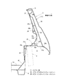
図1は自動車の側部車体構造を示した全体斜視図、図2は側部車体構造の全体側面図、図3は図2のA−A線矢視断面図、図4は図2のB−B線矢視断面図、図5は図2のC−C線矢視断面図、図6は図2のD−D線矢視断面図、図7は図2のE−E線矢視断面図である。
Hereinafter, the side body structure of the automobile of the present embodiment will be described based on the drawings.
1 is an overall perspective view showing a side body structure of an automobile, FIG. 2 is an overall side view of the side body structure, FIG. 3 is a cross-sectional view taken along line AA in FIG. 2, and FIG. 5 is a cross-sectional view taken along line CC in FIG. 2, FIG. 6 is a cross-sectional view taken along line DD in FIG. 2, and FIG. 7 is a cross-sectional view taken along line EE in FIG. It is sectional drawing.
なお、これらの図は、車内トリム等を装着していない状態を示している。また、これらの図は一方の車体側部のみを示しているが、他方の車体側部も対称な構造であり、詳細な説明は省略する。 In addition, these figures have shown the state which is not mounting | wearing with the in-vehicle trim. In addition, these drawings show only one vehicle body side portion, but the other vehicle body side portion also has a symmetrical structure, and a detailed description thereof will be omitted.
図1に示すように、本実施形態の車体構造は、主として、荷室床面を構成するフロア部1と、車体側面を構成する側壁部2と、車体後面を構成する後壁部3と、車体上面を構成するルーフ部4と、を備える。
As shown in FIG. 1, the vehicle body structure of the present embodiment mainly includes a
このうち、まず、フロア部1は、車幅方向及び車両前後方向に広がるフロアパネル5を、荷室下部に張設している。そして、フロアパネル5の下面には、車体後部の骨格部材である断面略ハット状のリアサイドフレーム6を、車両前後方向に延びるように接合している。
Among these, first, the
また、側壁部2は、その下部に車室側に膨出する半円形状のサスペンションタワー部(以下、サスタワー部)7を形成している。なお、このサスタワー部7は、内部に車輪(図示せず)を配置するため、このような半円形状の膨出形状としている。
Further, the
さらに、後壁部3には、リアゲートに対応するリアゲート開口部ROを設けている。そして、このリアゲート開口部ROの周縁には、リアインナパネル8とリアアウタパネル9とによって構成される閉断面を有するゲート開口縁部10を設けている。
Further, the
側壁部2のサスタワー部7の上方には、このサスタワー部7の近傍から斜め前方側上方に延びるCピラー部11を設けている。このCピラー部11の前方には、後席乗員の乗降用のサイドドア開口部DOを設けており、また、Cピラー部11の後方には、クォーターウィンドウ用のウィンドウ開口部WOを設けている。そして、このウィンドウ開口部WOの後方には、車体上下方向に亘って延びるDピラー部12を設けている。このDピラー部12は、前述のゲート開口縁部10の側部10aとして機能している。
Above the
また、側壁部2の上端には、車体において最も車両前方側に位置するAピラー部(図示せず)上端からDピラー部12上端まで車両前後方向に延びるルーフサイドレール部13を設置している。このルーフサイドレール部13に、前述のルーフ部4の車幅方向側端を連結している。
Further, a roof
次に、側壁部2等の構造について、特に、図2〜図7を利用して詳細に説明する。
Next, the structure of the
側壁部2は、図3に示すように、サイドインナパネル21とサイドアウタパネル22を接合することで、閉断面体として構成して、その内部にピラーアウタレインフォースメント(以下、ピラーアウタレイン)23を配設している。
As shown in FIG. 3, the
このピラーアウタレイン23は、下端部のフランジ23aをサイドインナパネル21の下部でサイドアウタパネル22側に膨出する膨出部21aに接合しており、Cピラー部11に向けて車両前方側に傾斜して略上下方向に延びて、Cピラー部11内を通って上端部のフランジ23bをルーフサイドレール部13及びサイドインナパネル21に接合している(図2、図3参照)。
The pillar
また、ピラーアウタレイン23は、図1に示すように、車体外方側に突出する断面ハット形状としており、両側の接合フランジ23cをサイドインナパネル21に接合することで、図3に示すような、閉断面X1を形成している。
Further, as shown in FIG. 1, the pillar
そして、このピラーアウタレイン23は、図2に示すように、Cピラー部11内を上下方向に延びてウィンドウ開口部WOの前端縁部及び下端縁部に沿って延びることで、Cピラー部11の剛性を向上すると共に、ウィンドウ開口部WOの前端縁部及び下端縁部が交差する隅部Rの剛性を向上している。
As shown in FIG. 2, the pillar
この隅部Rのサイドインナパネル21の車室側には、前方側斜め上方に延びるピラーインナレインフォースメント(以下、ピラーインナレイン)24を配設している。
A pillar inner reinforcement (hereinafter referred to as “pillar inner rain”) 24 extending obliquely upward on the front side is disposed on the side of the side
このピラーインナレイン24は、図3に示すように、上端部の接合フランジ24aをCピラー部11下部のサイドインナパネル21に接合して、中間部に車室側に突出する突出部24bを形成して、下端部の接合フランジ24cを後述するサスタワーレインフォースメント(以下、サスタワーレイン)31を介してサイドインナパネル21に接合している。また、図2に示すように、最下端部の接合フランジ24dは、サスタワー部7の車室側部材であるサスタワーパネル32にも接合している。
As shown in FIG. 3, the pillar
このピラーインナレイン24は、図3に示すように、突出部24bにおいて、サイドインナパネル21との間で閉断面X2を形成して、ウィンドウ開口部WOの前端縁部及び下端縁部が交差する隅部Rの剛性をさらに向上している。
As shown in FIG. 3, the pillar
また、このピラーインナレイン24は、図2に示すように、サスタワーレイン31とCピラー部11下部との間で前方側斜め上方に延びるように配置することで、サスタワーレイン31とCピラー部11を繋ぐ連結部材として機能することになり、後述するように、サスタワーレイン31に作用した後面衝突荷重(以下、衝突荷重)をCピラー部11に伝達する伝達部材として機能する。
In addition, as shown in FIG. 2, the pillar
サスタワー部7は、図1〜図3に示すように、車室側への半円形状の膨出部32aを形成したサスタワーパネル32を有する。このサスタワーパネル32の膨出部32aの周縁には、接合フランジ32bを形成しており、図3〜図5に示すように、この接合フランジ32bをサイドインナパネル21の縦面部21bの下部に接合している。こうして接合フランジ32bをサイドインナパネル21に接合することで、サスタワー部7内に、車輪を配置する配置空間Sを形成している。
As shown in FIGS. 1 to 3, the
ゲート開口縁部10は、図2に示すように、前述のように、リアインナパネル8とリアアウタパネル9とを有し、リアゲート開口部ROに沿う周縁端部で、各パネルのフランジ同士を接合することで、閉断面X3を形成している。
As shown in FIG. 2, the
このゲート開口縁部10は、その下部10bを、車幅方向全幅に亘って延びるように設置することで、車体後部の骨格部材たるクロスメンバー部材として機能している。そして、この閉断面X3内には、車両前後方向に延びる平板状の節部材40を設置している。この節部材40は、後述するように、車両後方側から作用する衝突荷重を車両前方側に伝達するために設けている。
The gate opening
ゲート開口縁部10の下方には、図2に示すように、リアサイドフレーム6に対応して断面ハット形状のバンパークロスメンバー50を設けている。また、このバンパークロスメンバー50の後方には、車両後方に延びる略ボックス状のクラッシュカン51を設けている。
Below the
また、図1に示すように、左右のサスタワー部7の間には、両サスタワー部7及びフロア部5の上面に沿って、車幅方向に延びて、その両端が左右のサスタワー部7の上部まで達する車体補強部材60を設けている。
Further, as shown in FIG. 1, between the left and right suspension towers 7, it extends in the vehicle width direction along the upper surfaces of both
この車体補強部材60は、車両後面視(または前面視)で両側端が上方に隆起した略U字形状として構成されており、左右のサスタワーレイン31と、左右のロアレイン61と、一本の連結クロスメンバー62とから構成している。以下、これらの構成要素について説明する。
The vehicle
まず、サスタワーレイン31は、図1〜図3に示すように、サスタワーパネル32の上部に配設しており、上部から下部にわたって車室側に膨出する膨出部31aと、これらの周囲に設けられた接合フランジ31b、31c、31dとを有する、断面ハット形状の逆L字状のガセット部材で構成している。
First, as shown in FIG. 1 to FIG. 3, the
そして、上部の接合フランジ31bをサイドインナパネル21の縦面部21bに接合して(図3参照)、両側部の接合フランジ31cをサスタワーパネル32の膨出部32a上面に接合して、下部の接合フランジ31dをサスタワーパネル32の膨出部32a側面に接合することで、図3に示すように、サスタワーレイン31の膨出部31aと、サスタワーパネル32の膨出部32aとの間に、上下二つの閉断面X4,X5を形成している。
Then, the upper
なお、サスタワーレイン31の膨出部31には、上部に矩形の作業穴31eを形成し、中間部に円形のダンパー取付け穴31fを形成している。また、ダンパー取付け穴31fの前後位置には、ボルト等を挿通するための二つの締結穴31gを形成している。
Note that a
ロアレイン61は、サスタワーレイン31とフロアパネル5とを連結するもので、サスタワーレイン31の下方に配設しており、車両前後方向略中央に、車室内方側へ膨出する膨出部61aと、車両前後方向両側に設けた接合フランジ61bと、を有する断面ハット形状のガセット部材で構成している。
The
そして、サスタワーレイン31の膨出部31aの下部と、このロアレイン61の膨出部61aの上部とを嵌め合わせた状態で、ロアレイン61の接合フランジ61bの上部をサスタワーレイン31の接合フランジ31dに接合して、接合フランジ61bの下部をフロアパネル5に接合して、車体に接合している。
Then, with the lower part of the bulging
また、連結クロスメンバー62は、左右のロアレイン61を連結するもので、フロアパネル5の上面に沿って車幅方向全幅に亘って延び、上方に膨出する膨出部62aと、接合フランジ62bとを有し、断面ハット形状のメンバー部材で構成している。
The connecting
そして、接合フランジ62bをフロアパネル5の上面に接合することで、連結クロスメンバー62とフロアパネル5とで閉断面を形成している。また、連結クロスメンバー62の車幅方向両端部においては、連結クロスメンバー62の膨出部62aの車幅方向端部と、ロアレイン61の膨出部61aの下部とを嵌め合わせた状態で接合している。
The
このように構成した車体構造において、さらに、本実施形態では、衝突荷重を伝達する複数の構成要素を設けている。 In the vehicle body structure configured as described above, in the present embodiment, a plurality of components that transmit the collision load are further provided.
まず、サスタワー部7の車両後方側には、サスタワー部7の上部からDピラー部12の中間部に向って側壁部2に沿って車両後方側斜め上方に延びる連結ガセット70を配設している。
First, on the vehicle rear side of the
この連結ガセット70は、平面視略方形状のプレート部材で構成しており、中央の平面部71と、この平面部71に対して折り曲げ形成した前端フランジ72、後端フランジ73、外側フランジ74、内側フランジ75とを有する。
The connecting
そして、前端フランジ72をサスタワーパネル32の膨出部32aの上面に接合して、後端フランジ73をDピラー部12のリアインナパネル8に接合して、外側フランジ74を側壁部2のサイドインナパネル21に接合している。一方、内側フランジ75は、連結ガセット70の剛性向上を図るものであり、他のフランジとは異なり、下方に折り曲げて形成している。
The
また、連結ガセット70における前端フランジ72の内端位置には延長部72aを設け、この延長部72aを、サスタワーレイン31の膨出部31a上面に接合している。これにより、連結ガセット70とサスタワーレイン31を連結している。
Further, an
この延長部72aでは、サスタワーパネル32と、サスタワーレイン31と、連結ガセット70とを三重に重合して接合すると共に、この延長部72aに設けられた締結穴72bに、サスペンション装置のダンパーD(図3参照)を取り付けるボルト部材(図示せず)を挿通することで、サスタワーパネル32と、サスタワーレイン31と、連結ガセット70とを、共締め固定するように構成している。このため、この延長部72aでは、連結ガセット70とサスタワーレイン31を強固に連結することができる。
In the
また、この連結ガセット70の下方には、連結ガセット70の前端下面からDピラー部12下方、すなわちゲート開口縁部10の下部10bに向って車両後方側斜め下方に延びる荷重伝達ガゼット80を配設している。
In addition, a
この荷重伝達ガゼット80は、断面コ字状のプレート部材で構成しており、中央の平面部81と、その両側で下方に折り曲げた折曲フランジ部82とを備えている。また、前端には連結ガセット70に接合される前端結合部83を折り曲げ形成して、後端にはゲート開口縁部10の下部10bに接合される後端結合部84を折り曲げ形成している。なお、後端結合部84が接合されるゲート開口縁部10の対応位置には、前述の節部材40を設けている。
This
図6、図7で、この荷重伝達ガセット80の結合部分の構造について、説明する。
図6に示すように、荷重伝達ガセット80の前端結合部83は、中央の平面部83aを連結ガセット70の平面部71の下面に対して接合している。このように、荷重伝達ガセット80の前端結合部83を連結ガセット70の平面部71に接合することで、荷重伝達ガセット80の前端結合部83をサスタワー部7の上部に直接接合しなくてもよいため、サスタワー部7の上部の構造を複雑にすることなく、また、連結ガセット70と荷重伝達ガセット80の組付け作業性も困難になることはない。
The structure of the coupling portion of the
As shown in FIG. 6, the front
また、後述するように、後面衝突の際には、衝突荷重を荷重伝達ガセット80から直接連結ガセット70に伝達できるため、確実にDピラー部12に衝突荷重を伝達することができる。
すなわち、仮にサスタワー部7に接合すると、衝突荷重がサスタワー部7側に全て伝達されて、そのままピラーインナレイン24を介してCピラー部11にだけ伝達される可能性が高まるが、連結ガセット70に直接接合しているため、衝突荷重を確実に連結ガセット70に伝達してDピラー部12に伝達することができるのである。
Further, as will be described later, in the event of a rear collision, the collision load can be transmitted directly from the
That is, if it joins to the
また、連結ガセット70の中央部ではなく、前端フランジ72に近接した前部に接合していることで、連結ガセット70に折れ曲りが生じるおそれをなくすことができ、確実に荷重伝達部材として機能させることができる。
Further, by joining not the central portion of the connecting
一方、図7に示すように、荷重伝達ガセット80の後端結合部84は、中央の平面部84aをゲート開口縁部10の下部で閉断面X3を構成するリアインナパネル8の前面に対して接合している。
On the other hand, as shown in FIG. 7, the rear
また、前述したように、この結合位置に対応して略コ字状に折り曲げ形成した節部材40を設置している。前端フランジ41をリアインナパネル8の後面(内側面)に接合して、後端フランジ42をリアアウタパネル9の前面(内側面)に接合することで、節部材40をゲート開口縁部10の閉断面X3内に固定している。
Further, as described above, the
このように、荷重伝達ガセット80の後端結合部84をゲート開口縁部10に接合することで、ゲート開口縁部10から入力される衝突荷重を、荷重伝達ガセット80に確実に伝達することができる。
Thus, by joining the rear
なお、このゲート開口縁部10への結合位置は、衝突荷重を確実に伝達するために、ゲート開口縁部10の車幅方向に延びる下部10bに設定するのが望ましいが、例えば、Dピラー部12である車幅方向側部10aの下端部に接合してもよい。
The coupling position to the
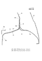
次に、このように構成した車体構造において、後面衝突時の衝突荷重の伝達経路について、図8の模式図を利用して説明する。なお、各構成要素は、図2と同一の符号を付して説明を省略する。 Next, in the vehicle body structure configured as described above, a transmission path of a collision load at the time of a rear collision will be described using the schematic diagram of FIG. Each component is denoted by the same reference numeral as in FIG.
後面衝突時においては、まず、車両後方から加害車両Zが衝突してくると、この衝突荷重(イ)は、始めにクラッシュカン51で初期の衝突エネルギーが吸収されてバンパークロスメンバー50に伝達される。
In the case of a rear collision, first, when the harm vehicle Z collides from the rear of the vehicle, this collision load (A) is first absorbed by the crash can 51 and transmitted to the
このバンパークロスメンバー50に伝達された衝突荷重(ロ)は、そのまま、車両前方側に延びるリアサイドフレーム6に伝達される。これにより、衝突エネルギーの一部が車体下部に分散される。
The collision load (b) transmitted to the
一方、ゲート開口縁部10の下部10bにも、加害車両Zが衝突することで、衝突荷重(ハ)が作用する。この衝突荷重(ハ)は、ゲート開口縁部10内の節部材40を介して荷重伝達ガセット80に伝達される。
On the other hand, a collision load (c) is also applied to the
この荷重伝達ガセット80に伝達された衝突荷重(ニ)は、連結ガセット70を介して、その前方に位置するサスタワー部7上部のサスタワーレイン31に伝達される。
The collision load (d) transmitted to the
そして、このサスタワーレイン31に伝達された衝突荷重(ホ)は、そのまま、車両前方側に位置するピラーインナレイン24とCピラー部11を介して、車体上端部のルーフサイドレール部13に伝達される。また、この衝突荷重(ホ)は、ピラーアウタレイン23を介して、直接サスタワーレイン31からルーフサイドレール部13に伝達される。
The collision load (e) transmitted to the
このため、衝突荷重(ホ)は、Cピラー部11を利用して、車体上部のルーフサイドレール部13に確実に伝達される。
For this reason, the collision load (e) is reliably transmitted to the roof
また、連結ガセット70に伝達された衝突荷重(へ)は、連結ガセット70の後端がDピラー部12に接合されていることで、Dピラー部12にも伝達される。すなわち、連結ガセット70を設けることで、Dピラー部12を利用して衝突荷重を車体上部に伝達しているのである。
Further, the collision load (f) transmitted to the
なお、この衝突荷重(へ)は、主として車両前方向きに作用するため、Dピラー部12には引っ張り荷重が作用することになるが、荷重伝達ガセット80を前端を上方に傾斜配置しているため、連結ガセット70には上向き分力(ト)も生じることになる。この上向き分力(ト)についても、連結ガセット70が後ろ上がりに傾斜配置されていることで、Dピラー部12に適切に伝達されることになる。
Since this collision load (f) acts mainly in the forward direction of the vehicle, a tensile load acts on the
こうして、Dピラー部12に伝達された衝突荷重(チ)は、ルーフサイドレール部13に伝達されることになり、Cピラー部11だけでなくDピラー部12も利用して、ルーフサイドレール部13に衝突荷重を伝達することができる。
Thus, the collision load (h) transmitted to the
よって、衝突エネルギーは、Cピラー部11とDピラー部12を利用して、車体上部にも分散されることになる。
Therefore, the collision energy is also distributed to the upper portion of the vehicle body using the
なお、この模式図からも分かるように、荷重伝達ガセット80の後端は、連結ガセット70の後端よりも、車両後方位置に設定している。このため、例えば、加害車両Z′がトラックのように車高が高い車であったとしても、必ず、最初に荷重伝達ガセット80に衝突荷重が伝達されることになり、常に前述した荷重伝達経路で衝突荷重が伝達されることになるため、車両の衝突安全性能を安定して高めることができる。
As can be seen from this schematic diagram, the rear end of the
次に、本実施形態の作用効果について説明する。
この実施形態の自動車の側部車体構造は、サスタワー部7のサスタワーレイン31とルーフサイドレール部13とを、ピラーインナレイン24とCピラー部11とで連結して、サスタワー部7の上部のサスタワーレイン31とゲート開口縁部10の下部10bとを略前後方向に延びる荷重伝達ガセット80で連絡して、サスタワーレイン31とDピラー部12を略前後方向に延びる連結ガセット70を連結している。
Next, the effect of this embodiment is demonstrated.
In the side body structure of the automobile of this embodiment, the
これにより、後面衝突時の衝突荷重をCピラー部11だけでなく、Dピラー部12も利用してルーフサイドレール部13に有効に伝達することができる。
このため、車体後部の側面にウィンドウ開口部WOを形成していても、衝突荷重を確実にルーフサイドレール部13に伝達することができる。
よって、車体後部の側面にウィンドウ開口部WOを形成した自動車の側部車体構造において、後面衝突のエネルギーを、車体下部だけでなく、車体上部にも適切に分散して、衝突安全性能を高めることができる。
特に、本実施形態では、車体剛性の高いサスタワー部7及びサスタワーレイン31を利用して、衝突エネルギーを分散しているため、より高い衝突荷重に対しても、適切にエネルギー分散を行なうことができる。
Thereby, the collision load at the time of the rear collision can be effectively transmitted to the roof
For this reason, even if the window opening WO is formed on the side surface of the rear portion of the vehicle body, the collision load can be reliably transmitted to the roof
Therefore, in the side body structure of a car with a window opening WO formed on the side of the rear part of the car body, the energy of rear collision is properly distributed not only to the lower part of the car body but also to the upper part of the car body to improve the collision safety performance. Can do.
In particular, in this embodiment, since the collision energy is dispersed using the
また、この実施形態では、荷重伝達ガセット80を側面視で前上がりに傾斜配置して、連結ガセット70を側面視で後上がりに傾斜配置している。
これにより、車両後方からの衝突荷重が、荷重伝達ガセット80からサスタワー部7の上部に伝達された際に、生じる上向き分力についても、後上がりに傾斜配置した荷重伝達ガセット80によって、Dピラー部12に適切に伝達することができる。
このため、衝突荷重の水平分力だけでなく、上向き分力についても、確実にDピラー部12に伝達することができる。
よって、より確実に、後面衝突の衝突荷重を、Dピラー部12を利用して、ルーフサイドレール部13に伝達することができる。
Further, in this embodiment, the
As a result, when a collision load from the rear of the vehicle is transmitted from the
For this reason, not only the horizontal component of the collision load but also the upward component can be reliably transmitted to the
Therefore, the collision load of the rear collision can be more reliably transmitted to the roof
また、この実施形態では、荷重伝達ガセット80の後端位置を、連結ガセット70の後端位置より車両後方側に設定している。
これにより、後面衝突時において、必ず最初に荷重伝達ガセット80に、衝突荷重が作用することになる。
このため、車高の高いトラック等が後方から衝突してきた場合であっても、常に、荷重伝達ガセット80から衝突荷重が作用することになるため、衝突荷重の伝達経路を、常に一定にすることができる。
よって、衝突してくる車両の種類に関係なく、常時安定して車体の衝突安全性能を高めることができる。
In this embodiment, the rear end position of the
Thereby, at the time of a rear surface collision, the collision load is always applied to the
For this reason, even when a truck with a high vehicle height collides from the rear, a collision load is always applied from the
Therefore, the collision safety performance of the vehicle body can be constantly improved regardless of the type of vehicle that collides.
また、この実施形態では、連結ガセット70の前端フランジ72の延長部72aを、サスタワー部7の上部のサスタワーレイン31に接合して、荷重伝達ガセット80の前端結合部83を、連結ガセット70のサスタワーレイン31との結合部分の近傍に接合している。
これにより、荷重伝達ガセット80の前端結合部83を、敢えて連結ガセット70の結合部分の近傍に結合したことで、荷重伝達ガセット80からの衝突荷重を、連結ガセット70に対して直接伝達することができる。
よって、連結ガセット70によるDピラー部12への衝突荷重の伝達を、より効率的に行なうことができ、衝突エネルギーの分散を確実に行なうことができる。
In this embodiment, the
Thereby, the front
Therefore, the collision load can be more efficiently transmitted to the
なお、参考例として、荷重伝達ガセット80の前端結合部83を、直接サスタワーレイン31に接合するように構成してもよい。このように構成した場合には、サスタワーレイン31での組付け作業が困難になるが、衝突荷重を直接サスタワーレイン31に伝達することができるため、車体剛性の高いサスタワー部7に、確実に衝突荷重を伝達することができる。
As a reference example , the front
また、この実施形態では、Cピラー部11の内部にピラーアウタレイン23を設けて、ルーフサイドレール部13とサスタワー部7を直接連結するように構成している。
これにより、サスタワー部7からCピラー部11を介してルーフサイドレール部13に伝達される衝突荷重を、より効率的にルーフサイドレール部13に伝達することができる。
このため、ウィンドウ開口部WOを設けたことで、剛性が十分でないCピラー部11であっても、確実に衝突荷重をルーフサイドレール部13に伝達することができる。
よって、Dピラー部12とCピラー部11を利用して、さらに確実に、衝突荷重をルーフサイドレール部13に伝達することができる。
In this embodiment, the pillar
Thereby, the collision load transmitted from the
For this reason, by providing the window opening WO, the collision load can be reliably transmitted to the roof
Therefore, the collision load can be more reliably transmitted to the roof
また、この実施形態では、ゲート開口縁部10の閉断面X3内に節部材40を設け、この節部材40を設けた位置に対応して荷重伝達ガセット80の後端結合部84を結合したものである。
これにより、後面衝突時におけるゲート開口縁部10の変形を抑制することができる。
このため、ゲート開口縁部10からの衝突荷重を、効率的に荷重伝達ガセット80に伝達することができる。
よって、確実に、荷重伝達ガセット80に衝突荷重を伝達でき、衝突エネルギーの車体上部への分散を確実に行なうことができる。
Further, in this embodiment, the
Thereby, the deformation | transformation of the gate opening
For this reason, the collision load from the
Therefore, the collision load can be reliably transmitted to the
また、この実施形態では、図2に示すように、Dピラー部12を、側面視で上部12aが車両前方側に傾斜するように中間位置に折曲部12bを備えるように形成して、この折曲部12bの上部に、連結ガセット70の後端フランジ73を結合している(図2参照)。
これにより、連結ガセット70からの衝突荷重が、折曲部12aを介することなくDピラー部12の直線部12cを利用してルーフサイドレール部13に直接伝達されることになる。
このため、折曲部12aを経由することによる、衝突荷重の伝達効率の悪化を抑制して、ルーフサイドレール部13に確実に衝突荷重を伝達することができる。
また、Dピラー部12が折曲げ形成されていることで、連結ガセット70からの車両前方側への引っ張り荷重に対して、Dピラー部12が変形しにくいため、より確実にDピラー部12を利用して衝突荷重をルーフサイドレール部13に伝達することができる。
よって、車体上部への衝突エネルギーの分散を、Dピラー部12を利用してより確実に行なうことができる。
Further, in this embodiment, as shown in FIG. 2, the
Thereby, the collision load from the
For this reason, it is possible to reliably transmit the collision load to the roof
Further, since the
Therefore, the collision energy can be more reliably distributed to the upper portion of the vehicle body using the
次に、図9に示す他の実施形態について説明する。なお、同一の構成要素については、前述の実施形態と同一の符号を付して説明を省略する。
この実施形態は、ゲート開口縁部10の下部10bからサスタワーレイン31に衝突荷重を伝達する部材をパイプ状の荷重伝達ビーム180で構成したものである。
Next, another embodiment shown in FIG. 9 will be described. In addition, about the same component, the code | symbol same as the above-mentioned embodiment is attached | subjected, and description is abbreviate | omitted.
In this embodiment, a member that transmits a collision load from the
荷重伝達ビーム180は、丸パイプで形成した本体部181と、平板プレート材で形成した前部結合金具182と、平板プレート材で形成した後部結合金具183とを備えており、前述の実施形態と同様に、連結ガセット70とゲート開口縁部10の下部10bとを、車両前後方向に延びて連結している。
The
このように、荷重伝達ビーム180を丸パイプで形成したことにより、車両前後方向剛性を、前述の実施形態の荷重伝達ガセット80よりも高くすることができるため、より大きな衝突荷重が車体後方から作用しても、確実に衝突荷重をサスタワー部7側に伝達することができる。
よって、衝突エネルギーをより確実に車体上部に分散することができる。
Thus, since the
Therefore, the collision energy can be more reliably distributed to the upper part of the vehicle body.
なお、前部結合金具182も後部結合金具183も共に、接合固定によって連結ガセット70等に結合しているが、その他にボルト・ナット等の締結手段を用いて結合固定するようにしてもよい。
Both the front coupling fitting 182 and the rear coupling fitting 183 are coupled to the
以上、この発明の構成と、前述の実施形態との対応において、
この発明のサイドピラーは、実施形態のCピラー部11に対応し、
以下、同様に
リアピラーは、Dピラー部12に対応し、
連結部材は、ピラーインナレイン24に対応し、
第一荷重伝達部材は、連結ガセット70に対応し、
第二荷重伝達部材は、荷重伝達ガセット80、荷重伝達ビーム180に対応し、
連結補強部材は、ピラーアウタレイン23に対応するも、
この発明は、前述の実施形態に限定されるものではなく、あらゆる自動車の側部車体構造の実施形態を含むものである。
As described above, in the correspondence between the configuration of the present invention and the above-described embodiment,
The side pillar of the present invention corresponds to the
Hereinafter, similarly, the rear pillar corresponds to the
The connecting member corresponds to the pillar
The first load transmitting member corresponds to the connecting
The second load transmission member corresponds to the
The connecting reinforcement member corresponds to the pillar
The present invention is not limited to the above-described embodiments, but includes embodiments of all vehicle side body structures.
7…サスペンションタワー部
11…Cピラー部
12…Dピラー部
13…ルーフサイドレール部
23…ピラーアウタレインフォースメント
24…ピラーインナレインフォースメント
40…節部材
70…連結ガセット
80…荷重伝達ガセット
180…荷重伝達ビーム
7 ...
Claims (6)
前記サスペンションタワーと車体上部で前後方向に延びるルーフサイドレールとを、前記サイドピラーを介して連絡する連結部材と、
前記サスペンションタワーの上部と前記リアゲート開口部の下方縁部とを略前後方向に延びて連絡する第一荷重伝達部材と、
前記サスペンションタワーの上部と前記リアピラーとを略前後方向に延びて連絡する第二荷重伝達部材を備え、
該第二荷重伝達部材の前端を、前記サスペンションタワーの上部に結合し、
前記第一荷重伝達部材の前端を、該第二荷重伝達部材のサスペンションタワーの上部への結合部近傍に結合した
自動車の側部車体構造。 A side pillar that forms a rear edge of the side door opening, a rear pillar that is disposed behind the side pillar with a window opening interposed therebetween to form a side edge of the rear gate opening, and the side pillar and the rear pillar. A side body structure of an automobile provided with a suspension tower disposed below the window opening,
A connecting member that connects the suspension tower and a roof side rail that extends in the front-rear direction at the top of the vehicle body via the side pillar;
A first load transmission member that extends and communicates with the upper portion of the suspension tower and the lower edge of the rear gate opening in a substantially front-rear direction;
A second load transmitting member that extends and communicates with the upper portion of the suspension tower and the rear pillar in a substantially front-rear direction ;
A front end of the second load transmission member is coupled to an upper portion of the suspension tower;
The side body structure of an automobile , wherein the front end of the first load transmission member is coupled in the vicinity of the coupling portion of the second load transmission member to the upper portion of the suspension tower .
前記第二荷重伝達部材を側面視で後上がりに傾斜配置した
請求項1記載の自動車の側部車体構造。 The first load transmitting member is inclined to the front as viewed from the side,
The side body structure of an automobile according to claim 1, wherein the second load transmission member is inclined rearward in a side view.
請求項1又は2記載の自動車の側部車体構造。 The side body structure of an automobile according to claim 1 or 2, wherein a rear end position of the first load transmission member is set to a vehicle rear side from a rear end position of the second load transmission member.
請求項1〜3いずれか記載の自動車の側部車体構造。 Wherein installed in the side pillar, connected upper end to the roof side rail reinforcing I lower end connected to the suspension tower, The rewritable connecting the suspension tower and the roof side rail directly to the side pillar The side part vehicle body structure of the motor vehicle in any one of Claims 1-3 provided with the connection reinforcement member to perform.
該リアゲート開口部の下方縁部の閉断面内に節部材を設け、
該節部材を設けた位置に対応して前記第一荷重伝達部材の後端を結合した
請求項1〜4いずれか記載の自動車の側部車体構造。 While forming the lower edge of the rear gate opening in a closed cross-sectional shape,
A node member is provided in the closed cross section of the lower edge of the rear gate opening,
The side part vehicle body structure of the automobile according to any one of claims 1 to 4, wherein a rear end of the first load transmission member is coupled in correspondence with a position where the node member is provided.
該折曲部の上部に、前記第二荷重伝達部材の後端を結合した
請求項1〜5いずれか記載の自動車の側部車体構造。 The rear pillar is formed so as to have a bent portion at an intermediate position between the upper and lower sides so that the upper part is inclined to the vehicle front side in a side view
The side body structure of an automobile according to any one of claims 1 to 5 , wherein a rear end of the second load transmission member is coupled to an upper portion of the bent portion.
Priority Applications (1)
| Application Number | Priority Date | Filing Date | Title |
|---|---|---|---|
| JP2007130073A JP5029135B2 (en) | 2007-05-16 | 2007-05-16 | Car side body structure |
Applications Claiming Priority (1)
| Application Number | Priority Date | Filing Date | Title |
|---|---|---|---|
| JP2007130073A JP5029135B2 (en) | 2007-05-16 | 2007-05-16 | Car side body structure |
Publications (2)
| Publication Number | Publication Date |
|---|---|
| JP2008284936A JP2008284936A (en) | 2008-11-27 |
| JP5029135B2 true JP5029135B2 (en) | 2012-09-19 |
Family
ID=40145106
Family Applications (1)
| Application Number | Title | Priority Date | Filing Date |
|---|---|---|---|
| JP2007130073A Expired - Fee Related JP5029135B2 (en) | 2007-05-16 | 2007-05-16 | Car side body structure |
Country Status (1)
| Country | Link |
|---|---|
| JP (1) | JP5029135B2 (en) |
Families Citing this family (23)
| Publication number | Priority date | Publication date | Assignee | Title |
|---|---|---|---|---|
| US8517455B2 (en) | 2009-09-04 | 2013-08-27 | Honda Motor Co., Ltd. | Structure for vehicle body rear portion |
| WO2012073753A1 (en) * | 2010-11-29 | 2012-06-07 | 本田技研工業株式会社 | Structure for rear part of vehicle body |
| JP5621587B2 (en) * | 2010-12-28 | 2014-11-12 | スズキ株式会社 | Quota structure |
| US9187130B2 (en) | 2011-08-02 | 2015-11-17 | Honda Motor Co., Ltd. | Vehicle body lateral structure |
| JP5544388B2 (en) * | 2012-03-29 | 2014-07-09 | 富士重工業株式会社 | Body front structure |
| CN102602460A (en) * | 2012-03-30 | 2012-07-25 | 重庆长安汽车股份有限公司 | Connecting structure for rear wheel guard assembly, rear side wall assembly and rear skirt board assembly of automobile |
| JP6200518B2 (en) * | 2013-11-19 | 2017-09-27 | 本田技研工業株式会社 | Body side structure |
| CN105235749B (en) * | 2014-07-09 | 2018-01-23 | 广州汽车集团股份有限公司 | Automotive back encloses reinforcement structure, automobile rear endergonic structure and automobile |
| CN104670336B (en) * | 2015-01-26 | 2017-11-17 | 上汽通用五菱汽车股份有限公司 | A kind of closed loop rear side wall |
| JP6259476B2 (en) * | 2016-01-13 | 2018-01-10 | 本田技研工業株式会社 | Vehicle rear structure |
| CN106564532A (en) * | 2016-10-12 | 2017-04-19 | 重庆比速汽车有限公司 | Penetrating structure of C column reinforcing plate and D column reinforcing plate |
| BR112019027802A2 (en) * | 2017-07-06 | 2020-07-07 | Honda Motor Co., Ltd. | vehicle body structure |
| CN107640225B (en) * | 2017-08-03 | 2023-11-17 | 重庆宇杰汽车设计有限公司 | Force transmission structure of rear suspension shock absorber of automobile |
| CN109823401B (en) * | 2017-11-23 | 2024-04-26 | 上汽通用五菱汽车股份有限公司 | Mounting assembly of rear independent suspension |
| JP6954185B2 (en) * | 2018-03-02 | 2021-10-27 | トヨタ自動車株式会社 | Vehicle rear structure |
| JP6540844B1 (en) * | 2018-03-06 | 2019-07-10 | マツダ株式会社 | Vehicle body structure |
| JP6540845B1 (en) * | 2018-03-06 | 2019-07-10 | マツダ株式会社 | Vehicle body structure |
| JP7106975B2 (en) * | 2018-05-10 | 2022-07-27 | マツダ株式会社 | vehicle body structure |
| JP7192322B2 (en) * | 2018-09-05 | 2022-12-20 | スズキ株式会社 | car body rear structure |
| CN111055926B (en) * | 2019-12-10 | 2022-03-18 | 东风柳州汽车有限公司 | Force transmission assembly of automobile rear shock absorber |
| CN113799878A (en) * | 2020-06-12 | 2021-12-17 | 广州汽车集团股份有限公司 | Automobile rear side wall structure and automobile |
| CN112092920A (en) * | 2020-08-13 | 2020-12-18 | 浙江零跑科技有限公司 | Novel shock absorber excitation load conduction structure |
| JP7307043B2 (en) * | 2020-12-09 | 2023-07-11 | トヨタ自動車株式会社 | car body |
Family Cites Families (5)
| Publication number | Priority date | Publication date | Assignee | Title |
|---|---|---|---|---|
| JP2001328562A (en) * | 2000-05-19 | 2001-11-27 | Mazda Motor Corp | Rear body structure for vehicle |
| JP4461810B2 (en) * | 2004-01-15 | 2010-05-12 | マツダ株式会社 | Rear body structure of the vehicle |
| JP2005306192A (en) * | 2004-04-21 | 2005-11-04 | Nissan Motor Co Ltd | Vehicle body rear part structure |
| JP4682561B2 (en) * | 2004-08-31 | 2011-05-11 | マツダ株式会社 | Rear body structure of the vehicle |
| JP4747745B2 (en) * | 2005-09-02 | 2011-08-17 | 日産自動車株式会社 | Mounting structure of reinforced connecting plate that connects between wheel house and back door pillar |
-
2007
- 2007-05-16 JP JP2007130073A patent/JP5029135B2/en not_active Expired - Fee Related
Also Published As
| Publication number | Publication date |
|---|---|
| JP2008284936A (en) | 2008-11-27 |
Similar Documents
| Publication | Publication Date | Title |
|---|---|---|
| JP5029135B2 (en) | Car side body structure | |
| JP5526644B2 (en) | Vehicle body structure | |
| US8857902B2 (en) | Front vehicle body structure | |
| JP4424208B2 (en) | Body front structure | |
| WO2013094190A1 (en) | Front sub-frame structure for automobiles | |
| JP4556674B2 (en) | Vehicle side body structure | |
| JP4875558B2 (en) | Body frame structure | |
| JP4875559B2 (en) | Body frame structure | |
| JP2013159290A (en) | Lower vehicle-body structure of vehicle | |
| JP2008105561A (en) | Vehicle front part structure | |
| JP6131967B2 (en) | Auto body structure | |
| JP5870673B2 (en) | Front subframe structure of automobile | |
| JP2008230460A (en) | Lower body structure of vehicle | |
| JP2013169806A (en) | Vehicle body lower structure | |
| JP4923406B2 (en) | Body front structure | |
| JP2008137483A (en) | Vehicle body front part structure | |
| JP5321334B2 (en) | Vehicle cowl structure | |
| JP5353364B2 (en) | Lower body structure of the vehicle | |
| JP2021075089A (en) | Vehicle lower part structure | |
| JP2010000866A (en) | Front body structure of vehicle | |
| JP6098649B2 (en) | Auto body structure | |
| JP5402010B2 (en) | Lower body structure of the vehicle | |
| JP2008230459A (en) | Lower body structure of vehicle | |
| JP5509265B2 (en) | Body front structure | |
| JP2010247610A (en) | Vehicle body rear structure |
Legal Events
| Date | Code | Title | Description |
|---|---|---|---|
| A621 | Written request for application examination |
Free format text: JAPANESE INTERMEDIATE CODE: A621 Effective date: 20100212 |
|
| A977 | Report on retrieval |
Free format text: JAPANESE INTERMEDIATE CODE: A971007 Effective date: 20111031 |
|
| A131 | Notification of reasons for refusal |
Free format text: JAPANESE INTERMEDIATE CODE: A131 Effective date: 20111101 |
|
| TRDD | Decision of grant or rejection written | ||
| A01 | Written decision to grant a patent or to grant a registration (utility model) |
Free format text: JAPANESE INTERMEDIATE CODE: A01 Effective date: 20120529 |
|
| A01 | Written decision to grant a patent or to grant a registration (utility model) |
Free format text: JAPANESE INTERMEDIATE CODE: A01 |
|
| A61 | First payment of annual fees (during grant procedure) |
Free format text: JAPANESE INTERMEDIATE CODE: A61 Effective date: 20120611 |
|
| R150 | Certificate of patent or registration of utility model |
Ref document number: 5029135 Country of ref document: JP Free format text: JAPANESE INTERMEDIATE CODE: R150 Free format text: JAPANESE INTERMEDIATE CODE: R150 |
|
| FPAY | Renewal fee payment (event date is renewal date of database) |
Free format text: PAYMENT UNTIL: 20150706 Year of fee payment: 3 |
|
| LAPS | Cancellation because of no payment of annual fees |