JP2016009082A - Authenticity determination tool - Google Patents
Authenticity determination tool Download PDFInfo
- Publication number
- JP2016009082A JP2016009082A JP2014129562A JP2014129562A JP2016009082A JP 2016009082 A JP2016009082 A JP 2016009082A JP 2014129562 A JP2014129562 A JP 2014129562A JP 2014129562 A JP2014129562 A JP 2014129562A JP 2016009082 A JP2016009082 A JP 2016009082A
- Authority
- JP
- Japan
- Prior art keywords
- authenticity determination
- transmitted light
- light
- true
- polarizing plate
- Prior art date
- Legal status (The legal status is an assumption and is not a legal conclusion. Google has not performed a legal analysis and makes no representation as to the accuracy of the status listed.)
- Pending
Links
Images


Abstract
Description
本発明は、真偽判定体の真偽判定をおこなう真偽判定具に関するものである。 The present invention relates to a true / false determining tool for performing true / false determination of a true / false determining object.
例えば、クレジットカード、預貯金用カード、各種金券、もしくは身分証明書等は、偽造や改ざんがされて不正に使用されるといろいろな支障を招くので、偽造や改ざんによる損害を防止するために、そのものの真正性を識別できる機能を有することが望まれている。また、例えば、腕時計、皮革製品、貴金属製品もしくは宝飾品等の高級品、とりわけ、高級ブランド品と言われるもの、オーディオ製品、電化製品、または媒体に記録された音楽ソフト、映像ソフト、ゲームソフト、もしくはコンピュータソフトも、やはり偽造の対象となるので、同様に、真正性を識別できる機能を有することが望まれている。 For example, credit cards, savings cards, various vouchers, or identification cards, etc., cause various troubles if they are counterfeited or tampered with and used improperly, so in order to prevent damage caused by forgery or tampering It is desired to have a function that can identify the authenticity of the. In addition, for example, luxury products such as wristwatches, leather products, precious metal products or jewelry, in particular, what are said to be luxury brand products, audio products, electrical appliances, music software recorded on media, video software, game software, Alternatively, computer software is also subject to counterfeiting, and similarly, it is desired to have a function capable of identifying authenticity.
従来、上記の物品も含めた種々の物品の真正性の識別を可能にする目的で、ホログラムが多用されている。ホログラムは、その構造の精密さから、製造上の困難性を有するからである。しかし、ホログラムの製造方法は専門家には知られており、また、精密なものであるだけに、真正なホログラムと偽造されたホログラムとの区別はなかなかに困難である。 Conventionally, holograms are frequently used for the purpose of enabling authenticity identification of various articles including the above-mentioned articles. This is because the hologram has manufacturing difficulties due to the precision of its structure. However, the method of manufacturing a hologram is known to experts, and since it is precise, it is difficult to distinguish between a genuine hologram and a forged hologram.
そこで、ホログラムに代るものとして、例えば、特許文献1では、基材と、基材の一方の面に形成され、入射した光のうち、左回り偏光又は右回り偏光のいずれか一方の光のみを反射する光選択反射層と光選択反射層の少なくとも一部に形成され、新製品を判定する判定情報を備える判定部とを有する真偽判定体と、円偏光版を用いた真偽判定具が提案されている。
Therefore, as an alternative to a hologram, for example, in
また、特許文献2では、2層の光選択反射層が前記2層の間に位相差層を介して積層された積層構造を有しており、前記2層の光選択反射層は入射光のうち左円偏光もしくは右円偏光のいずれか一方であって同じ方向の円偏光を反射する光選択反射性を有する素材から構成され、かつ、前記2層の光選択反射層の反射光の中心波長どうしが互いに異なるものであり、前記積層構造の一方の面上に光回折構造層が積層されており、前記光回折構造層が反射型ホログラム又は光反射性層をともなった層であることを特徴とする真偽判定体と、円偏光版を用いた真偽判定具が提案されている。
Further, in
しかし、特許文献1、2のような真偽判定具では、真偽判定体の“真”か“偽”かを、観察者が直感的に判断することが難しい。本明細書内で、“真”とは、真偽判定体が真正品であることを意味し、 “偽”とは、真偽判定体が真正品ではないことを意味する。
However, it is difficult for the observer to intuitively determine whether the true / false determination object is “true” or “false” with the authenticity determination tools such as
特許文献3では、コレステリック液晶層上に所定のパターンを有して設けられた1/2波長板として機能する液晶層を有する真偽判定体が記載され、真偽判定具である円偏光フィルターを通して所定のパターンが、所定の一色と黒色で認識できる識別媒体が提案されている。 Patent Document 3 describes an authenticity determination body having a liquid crystal layer that functions as a half-wave plate provided with a predetermined pattern on a cholesteric liquid crystal layer, and passes through a circular polarizing filter that is an authenticity determination tool. An identification medium has been proposed in which a predetermined pattern can be recognized by a predetermined color and black.
しかし、このような真偽判定体は、“真”であることを示す前記所定のパターンを個々の媒体に作り込む必要があり、真偽判定にかかるコストの低減が難しい。 However, it is necessary for such a true / false determination object to create the predetermined pattern indicating “true” in each medium, and it is difficult to reduce the cost for the true / false determination.
本発明の課題は、真偽判定体が、真偽判定体の“真”か“偽”かを、観察者が直感的に判断することが可能であり、真偽判定にかかるコストの低減することが可能である、真偽判定具を提供することである。 An object of the present invention is to enable an observer to intuitively determine whether a true / false judgment object is “true” or “false”, and reduce the cost of authenticity judgment. It is possible to provide a true / false judgment tool.
本発明の「真偽判定」とは、真偽判定体が“真”なのか“偽”なのかを判定する作業をいい、「観察者」とは、真偽判定体が“真”なのか“偽”なのかを目視で真偽判定をおこなう判定者をいい、「真偽判定具」とは、真偽判定体が“真”なのか“偽”なのかを判定するために用いる道具のことをいい、「真偽判定体」とは、“真”なのか“偽”なのかの真偽判定をされる物品をいう。 The “true / false judgment” of the present invention refers to an operation for judging whether the true / false judgment object is “true” or “false”, and the “observer” means whether the true / false judgment object is “true”. A judge who visually verifies whether it is “false”. A “true / false judgment tool” is a tool used to judge whether a true / false judgment object is “true” or “false”. The “true / false judgment object” refers to an article for which a true / false judgment is made as to whether it is “true” or “false”.
本発明の第1の発明は、右円偏光板または左円偏光板と、前記右円偏光板または左円偏光板の一方の面側にパターン状に積層された位相差板フィルムと、を有する透過光観察部を備えることを特徴とする真偽判定具に関する。 1st invention of this invention has a right circularly-polarizing plate or a left circularly-polarizing plate, and the phase difference plate film laminated | stacked in the pattern form on one surface side of the said right-circularly polarizing plate or the left-circularly polarizing plate The present invention relates to a true / false determination tool including a transmitted light observation unit.
前記位相差板フィルムが、1/2波長板フィルムであっても良い。 The retardation film may be a half-wave plate film.
本発明の第2の発明は、右円偏光板と、前記右円偏光板の一方の面側にパターン状に積層された位相差板フィルムと、を有する第1の透過光観察部と、左円偏光板と、前記左円偏光板の一方の面側にパターン状に積層された位相差板フィルムと、を有する第2の透過光観察部と、
を備えることを特徴とする真偽判定具関する。
According to a second aspect of the present invention, there is provided a first transmitted light observation unit including a right circularly polarizing plate and a retardation film laminated in a pattern on one surface side of the right circularly polarizing plate; A second transmitted light observation unit having a circularly polarizing plate and a retardation film laminated in a pattern on one surface side of the left circularly polarizing plate;
It is related with the authenticity determination tool characterized by providing.
前記第1の透過光観察部の位相差板フィルムと、前記第2の透過光観察部の位相差板フィルムとが、1/2波長板フィルムであっても良い。 The retardation plate film of the first transmitted light observation unit and the retardation plate film of the second transmitted light observation unit may be half-wave plate films.
本発明の真偽判定具により、円偏光を反射する真偽判定体の真偽判定を、観察者が直感的に判断すること可能となり、真偽判定にかかるコストを低減することが可能となる。 With the authenticity determination tool of the present invention, it becomes possible for the observer to intuitively determine the authenticity determination of the authenticity determination object that reflects circularly polarized light, and the cost for authenticity determination can be reduced. .
本形態は、観察者が目視により真偽判定をおこなう真偽判定具に関するものであり、直感的な真偽判定が可能となるように、文字または記号等のパターンを表示することにより、真偽判定のための情報を観察者に提供するものである。 The present embodiment relates to a true / false determination tool that allows an observer to make a true / false determination visually, and displays a pattern such as a character or a symbol so that an intuitive authenticity determination is possible. Information for determination is provided to the observer.
一般的に、真偽判定は、圧倒的に多数の真偽判定体に対し、少数の真偽判定具を用いておこなわれる。このような圧倒的に多数の前記真偽判定体ではなく、少数の前記真偽判定具に対して前記真偽判定情報をパターン状に形成する加工を施すことにより、加工費を減少することにより、真偽判定にかかるコストを低減するものである。
1.真偽判定
本形態の真偽判定具は、観察者が、真偽判定体からの反射光を観察し、真偽判定をおこなうために用いられる。本形態の真偽判定具を用いる真偽判定体は、1種類または2種類の特定の波長を有し、特定の円偏光性を有する光を反射する。
Generally, the authenticity determination is performed using an extremely small number of authenticity determination tools for an extremely large number of authenticity determination objects. By reducing the processing cost by applying the processing for forming the authenticity determination information in a pattern for a small number of the authenticity determination tools instead of the overwhelmingly large number of the authenticity determination bodies. The cost for authenticity determination is reduced.
1. Authenticity determination The authenticity determination tool of the present embodiment is used for an observer to observe reflected light from an authenticity determination body and perform authenticity determination. The authenticity determination body using the authenticity determination tool of this embodiment has one or two specific wavelengths and reflects light having a specific circular polarization property.
4−1.反射光が1種類の場合
真偽判定体が、図3(a)、図5(a)に示すように、入射する自然光に対して、光選択反射層41により、特定の波長の、右または左の円偏光を反射する真偽判定体2を用いた場合の真偽判定について説明する。
4-1. When there is one kind of reflected light
As shown in FIGS. 3A and 5A, the authenticity determination body reflects right or left circularly polarized light having a specific wavelength by the light
真偽判定体の光選択反射層が、赤色の右円偏光を反射する材料で形成されている場合を仮定して説明する。 A description will be given assuming that the light selective reflection layer of the authenticity determination body is formed of a material that reflects red right circularly polarized light.
真偽判定具には、観察者と反対側から前記赤色の右円偏光が入射する。
ここで、前記真偽判定具の透過光観察部が右円偏光を通す円偏光板を有し、図3(b)に示すように位相差板フィルムが「True」のパターン状に形成されている場合、観察者は、赤い背景に、暗い赤色、黒色、または黒に近い灰色で表示される「True」というパターンを観察することができる。真偽判定体が“偽”で、反射光が選択されていない場合は、パターンの観察はできない。
The red right circularly polarized light is incident on the authenticity determination tool from the side opposite to the observer.
Here, the transmitted light observation part of the authenticity determination tool has a circularly polarizing plate that allows right-handed circularly polarized light to pass therethrough, and the retardation film is formed in a “True” pattern as shown in FIG. If so, the observer can observe a pattern of “True” that is displayed on a red background in dark red, black, or gray close to black. When the true / false judgment object is “false” and the reflected light is not selected, the pattern cannot be observed.
前記真偽判定具の透過光観察部が右円偏光を通す円偏光板を有し、位相差板フィルムが「True」のパターンを中抜きで形成されている場合、観察者は、暗い赤色、黒色、または黒に近い灰色の背景に、赤で表示される「True」というパターンを観察することができる。真偽判定体が“偽”で、反射光が選択されていない場合は、パターンの観察はできない。 When the transmitted light observation part of the authenticity determination tool has a circularly polarizing plate that allows right-handed circularly polarized light to pass therethrough, and the retardation film is formed with a hollow pattern of “True”, the observer is dark red, A pattern “True” displayed in red on a black background or a gray background close to black can be observed. When the true / false judgment object is “false” and the reflected light is not selected, the pattern cannot be observed.
真偽判定体の光選択反射層が、赤色の左右円偏光を反射する材料で形成されている場合は、上述の場合とは逆の見え方になる。 When the light selective reflection layer of the authenticity determination body is formed of a material that reflects red left and right circularly polarized light, the appearance is opposite to that described above.
位相差板フィルムのパターンをより明確に認識するために、上記透過光観察部の位相差板フィルムが、1/2波長板フィルムであることが好ましい。位相差板フィルムが1/2波長板フィルムであれば、1/2波長板フィルムを通った右円偏光が左円偏光になり、右円偏光を通す円偏光板を通らなくなるためである。 In order to recognize the pattern of the retardation film more clearly, it is preferable that the retardation film of the transmitted light observation part is a half-wave plate film. This is because if the retardation film is a half-wave plate film, the right circularly polarized light that has passed through the half-wave plate film becomes left-handed circularly polarized light and cannot pass through the circularly polarizing plate that passes the right-hand circularly polarized light.
真偽判定体からの反射光が特定の波長の光のみで、完全な一方向の円偏光を反射し、真偽判定具の位相差板フィルムが完全な1/2波長板フィルムで、真偽判定具の円偏光板が前記一方向の円偏光のみを通す理想的な状態であれば、前記特定の波長の光の色の背景に、1/2波長板フィルムのパターンが黒色で観察される。
しかし、実際に作製することができる真偽判定体、および真偽判定具は、光の波長および位相がばらつきを有している。このため、位相差板フィルムが完全な1/2波長板フィルムでなくとも、観察者は真偽判定具の透過光を観察することにより真偽判定を行なうことができる。
The reflected light from the true / false judgment body reflects only one direction of circularly polarized light with only a specific wavelength, and the retardation plate film of the true / false judgment tool is a perfect half-wave plate film. If the circularly polarizing plate of the determination tool is in an ideal state where only the circularly polarized light in one direction passes, the pattern of the half-wave plate film is observed in black on the background of the color of the light having the specific wavelength. .
However, the authenticity determination body and the authenticity determination tool that can be actually manufactured have variations in the wavelength and phase of light. For this reason, even if the phase difference plate film is not a complete half-wave plate film, the observer can determine the authenticity by observing the transmitted light of the authenticity determination tool.
1−2.反射光が2種類の場合
真偽判定体が、図4(a)、図5(b)に示すように、入射する自然光に対して、特定の波長で、右または左のうち一方向に円偏光された第1の反射光と、前記特定の波長とは異なる波長で、前記円偏光と同じ方向に円偏光された第2の反射光とを反射する真偽判定体2を用いた場合の真偽判定について説明する。
1-2. When there are two types of reflected light
As shown in FIGS. 4 (a) and 5 (b), the true / false determining body is a first reflection that is circularly polarized in one direction of right or left at a specific wavelength with respect to incident natural light. The authenticity determination in the case where the
真偽判定体の第1の光選択反射層が赤色の右円偏光を反射する材料で形成され、第2の光選択反射層が青色の左円偏光を反射する材料で形成されている場合を仮定して説明する。 The case where the first light selective reflection layer of the authenticity determination body is formed of a material that reflects red right circularly polarized light, and the second light selective reflection layer is formed of a material that reflects blue left circularly polarized light. An explanation will be given.
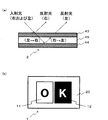
真偽判定具には、観察者と反対側から赤色の右円偏性の第1の反射光と、青色の左円偏性の第2の反射光とが入射する。ここで、前記真偽判定具の第1の透過光観察部が右円偏光を通す円偏光板を有し、第2の透過光観察部が左円偏光を通す円偏光板を有し、図4(b)に示すように、第1の透過光観察部に「O」、第2の透過光観察部に「K」のパターン状に位相差板フィルムが形成されている場合、観察者は、第1の透過光観察部は、前記第1の反射光のみが透過し位相差板フィルムは、主に第2の反射光が透過するので、赤色の背景に、青色または青色と赤色が合成された色で表示される「O」というパターンを観察することができる。第2の透過光観察部では、同様の理由で、青色の背景に、赤色または青色と赤色が合成されたで表示される「K」というパターンを、観察することができる。真偽判定体が“偽”で、反射光が選択されず、円偏光が反射されない場合は、パターンの観察はできない。 Red right-circular first reflected light and blue left-circular second reflected light are incident on the authenticity determination tool from the side opposite to the observer. Here, the first transmitted light observation unit of the authenticity determination tool has a circularly polarizing plate that transmits right circularly polarized light, and the second transmitted light observation unit has a circularly polarizing plate that transmits left circularly polarized light. When the retardation film is formed in a pattern of “O” in the first transmitted light observation unit and “K” in the second transmitted light observation unit as shown in FIG. The first transmitted light observation unit transmits only the first reflected light, and the retardation film mainly transmits the second reflected light. Therefore, blue or blue and red are combined on a red background. The pattern “O” displayed in the selected color can be observed. For the same reason, the second transmitted light observation unit can observe the pattern “K” displayed by combining red and blue and red on a blue background. If the true / false judgment is “false”, the reflected light is not selected and the circularly polarized light is not reflected, the pattern cannot be observed.
位相差板フィルムのパターンがより明確に認識するために、上記透過光観察部の位相差板フィルムが、1/2波長板フィルムであることが好ましい。理由は、反射光が1種類の場合と同様である。 In order to recognize the pattern of the retardation film more clearly, it is preferable that the retardation film of the transmitted light observation part is a half-wave plate film. The reason is the same as when the reflected light is one type.
2.真偽判定具
本形態の真偽判定具の一例を、図1(a)に示す。図1(a)に示す例では、真偽判定具10は、透過光観察部10と、前記透過光観察部10を支持する枠体20を有している。本形態の真偽判定具は、前記透過光観察部10が、取り扱い上問題がない程度の高い剛性を有していれば、枠体20は無くてもよいが、保管時などに発生する汚れや傷などの発生を防止するために、枠体20を有しているほうが好ましい。
2. An example of the authenticity determination tool of this form is shown in FIG. In the example illustrated in FIG. 1A, the
前記透過光観察部10は、右または左の円偏光板31と、前記右または左の円偏光板の一方の面側にパターン状に積層された位相差板フィルム32と、を有する。前記真偽判定具1を真偽判定に使用するときは、図1(b)に示すように、観察者側に円偏光板31面を、真偽判定体側に位相差板フィルム32面を向けて使用する。
The transmitted
前記位相差板フィルム32が1/2波長板フィルムであると、反射光の透過と遮断の状況が理想的な状態に近づくので、より明確にパターンを認識できる。
When the
また、本形態の真偽判定具1は、図1(a)に示すように、一つの透過光観察部10の中に第1の透過光観察部と、第2の透過光観察部を有していてもよく、図2(a)に示すように、枠体20と、前記枠体20に支持された第1の透過光観察部11と、第2の透過光観察部12と、を有していてもよい。本形態の真偽判定具は、前記透過光観察部10が、取り扱い上問題がない程度の高い剛性を有していれば、枠体20は無くてもよいが、保管時などに発生する汚れや傷などの発生を防止するために、枠体20を有しているほうが好ましい。
Further, as shown in FIG. 1A, the
真偽判定具1が、第1の透過光観察部11と、第2の透過光観察部12と、を有する場合、第1の透過光観察部11は、右または左どちらかの円偏光性を有する円偏光板33を有し、第2の透過光観察部12は、前記第1の透過光観察部11に用いた円偏光板33とは逆の円偏光性を有する円偏光板34を有することが好ましい。
When the
前記第1の透過光観察部11と第2の透過光観察部12とは、それぞれ、円偏光板と、前記円偏光板の一方の面側にパターン状に積層された位相差板フィルムと、を有する。前記真偽判定具1を真偽判定に使用するときは、図1(b)に示すように、観察者側に円偏光板31面を、真偽判定体側に位相差板フィルム32面を向けて使用する。
The first transmitted
透過光観察部10、第1の透過光観察部11、および第2の透過光観察部12に用いる前記円偏光板の偏光方向は、例えば図3(a)、図4(a)に示すような真偽判定体からの反射光の偏光方向、および透過光観察部10での表示色の選択などをふまえて、任意に選択することができる。
The polarization directions of the circularly polarizing plates used in the transmitted
枠体20は、前記透過光観察部10、第1の透過光観察部11、および第2の透過光観察部12を保持するための機能を有していればよく、透過光観察部10のみでも取り扱いに十分な剛性を有することにより枠体20が必要でない場合は、枠体20はなくてもよい。また、枠体20は、透過光観察部10を保持するための機能を有していればよく、どのような材質を用いてもよい。取り扱いのしやすさ、製造のしやすさ、コスト等の点で、プラスチック製のシートや厚紙を用いることが好ましい。
The
また、前記透過光観察部10は、図1(a)に示すような穴部を有する枠体20の、一方の面に固定してあってもよく、2枚の枠体に挟まれて固定されていてもよい。
Further, the transmitted
3.透過光観察部
透過光観察部は、上記のように、観察者側から、順に、円偏光板、位相差板フィルムを有する。
3. Transmitted light observation part The transmitted light observation part has a circularly-polarizing plate and a retardation film in order from the observer side as described above.
3−1.円偏光板
円偏光板は、直線偏光フィルムと1/4波長板とを有する。
3-1. Circularly polarizing plate The circularly polarizing plate has a linearly polarizing film and a quarter-wave plate.
3−1−1.直線偏光フィルム
直線偏光フィルムは、直線偏光機能を有していればよく、液晶ディスプレイ等で使用されるヨウ素系偏光フィルム、染料系偏光フィルム等を用いることができる。
3-1-1. Linear Polarizing Film The linear polarizing film only needs to have a linear polarizing function, and iodine-based polarizing films, dye-based polarizing films and the like used in liquid crystal displays and the like can be used.
3−1−2.1/4波長板層
前記直線偏光フィルムの吸収軸に対し、1/4波長板+45度で組み合わせれば右円偏光板を形成することでき、−45度で組み合わせれば左円偏光板を形成することができる。1/4波長板は、には、複屈折性を有する材料を、1/4波長の位相差を発生できる厚さに形成してあればよい。例えば、複屈折性を有する液晶等の塗布可能な材料や、PETフィルム、ポリカーボネートまたはセロファンフィルムなどの複屈折性を有するフィルムを用いることができる。PETフィルムを用いた場合、視認性、作業性(貼りやすさ)を考慮すると、厚さは25〜100μmが好ましい。
3-1.2.1 / 4 Wave Plate Layer A right circularly polarizing plate can be formed by combining at 1/4 wave plate + 45 degrees with respect to the absorption axis of the linearly polarizing film, and if combined at −45 degrees. A left circularly polarizing plate can be formed. The quarter-wave plate may be formed of a birefringent material having a thickness capable of generating a quarter-wave phase difference. For example, a coatable material such as liquid crystal having birefringence, or a film having birefringence such as a PET film, polycarbonate, or cellophane film can be used. When a PET film is used, the thickness is preferably 25 to 100 μm in view of visibility and workability (ease of sticking).
3−2.位相差板フィルム
位相差板フィルムは、光が前記位相差板フィルムを透過することにより、入射した前記光の位相に変化を与える。位相差板フィルムが1/2波長板フィルムである場合は、入射した右円偏光は左円偏光に、入射した左円偏光は右円偏光に、のように、入射してきた光の円偏光方向を逆転させることができる。
3-2. The retardation plate film changes the phase of the incident light when light passes through the retardation plate film. When the retardation film is a half-wave plate film, the incident right circularly polarized light is left circularly polarized light, the incident left circularly polarized light is right circularly polarized light, and so on. Can be reversed.
このような位相差板フィルムには、複屈折性を有するフィルム材料を用いることができる。1/2波長板フィルムを形成する場合は、前記複屈折性を有する材料の膜厚を調整し、1/2波長の位相差を発生できる厚さに形成すればよい。例えば、PETフィルム、ポリカーボネート、またはセロファンフィルムなどの複屈折性を有するフィルムを用いることができる。 A film material having birefringence can be used for such a retardation film. In the case of forming a half-wave plate film, the thickness of the birefringent material may be adjusted to a thickness that can generate a half-wave phase difference. For example, a birefringent film such as a PET film, a polycarbonate, or a cellophane film can be used.
本形態において、位相差板フィルム32は、パターン状に積層される。前記位相差板フィルム32のパターンは、どのように表示されれば“真”なのか“偽”なのかを事前に決めてあればどのようなパターンでもよいが、観察者が直感的に物品の“真”、“偽”を目視で判定できるようなパターンが形成されていることが好ましい。例えば、図3(b)、図4(b)に示すように「True」、「OK」などの文字でもよく、「○」などの記号でもよい。
In this embodiment, the
4.真偽判定体
真偽判定に、本形態の真偽判定具を用いる真偽判定体は、特定の円偏光を反射すればよい。
4). Authenticity determination body The authenticity determination body using the authenticity determination tool of the present embodiment for authenticity determination may reflect a specific circularly polarized light.
例えば、図3(a)に示すように、入射する自然光に対して、光選択反射層41により、特定の波長の、右または左の円偏光を反射する真偽判定体2を用いることができる。
For example, as shown in FIG. 3A, the
このような光選択反射層41には、例えば、高分子コレステリック液晶を用いることができる。必要に応じて、カイラル剤および紫外線重合開始剤を含んでいても良い。
For such a light
また、光選択反射層として、上記のコレステリック液晶層だけでなく、例えば、見る角度によって色が変化する顔料を用いる、蒸着薄膜を用いる、もしくは二色性色素を用いることにより構成することができる。見る角度によって色が変化する顔料としては、高屈折率の酸化ケイ素、酸化チタン、酸化鉄などの層と、低屈折率のマイカ等の層を積層したパール顔料を例示することができ、具体的には、( 株) 資生堂製の商品名; インフィニットカラーや、メルク社( 独国) 製の商品名; イリオジン等が入手可能である。蒸着薄膜はアルミニウム等の金属やそのほかの素材を気相法により薄膜として形成したもので、水面に浮かんだ油の薄膜のようないわゆる干渉色を示すものである。二色性色素は、分子軸の方向によって光の吸収性を相違する長鎖色素分子からなり、例えば、色素分子の分子軸の方向に対して法線方向の光成分は吸収性がほぼなく光を透過するのに対して、分子軸の方向に対して平行方向の光成分は吸収性を有し、光を透過しない性質を有するもので、アントラキノン系、アゾ系、もしくはビスアゾ系の色素を例示することができる。 In addition to the cholesteric liquid crystal layer, the light selective reflection layer can be configured by using, for example, a pigment whose color changes depending on the viewing angle, a vapor deposition thin film, or a dichroic dye. Examples of pigments whose color changes depending on the viewing angle include pearl pigments in which layers of high refractive index silicon oxide, titanium oxide, iron oxide, and the like, and layers of low refractive index mica, etc. are laminated. Are available under the trade names of Shiseido Co., Ltd .; Infinite Color and Merck (Germany); The deposited thin film is formed by forming a metal such as aluminum or other material as a thin film by a vapor phase method, and exhibits a so-called interference color like an oil thin film floating on the water surface. A dichroic dye is composed of long-chain dye molecules that have different light absorption depending on the direction of the molecular axis. For example, the light component in the normal direction relative to the direction of the molecular axis of the dye molecule has almost no absorption. The light component in the direction parallel to the direction of the molecular axis has an absorptive property and does not transmit light, and examples include anthraquinone, azo, or bisazo dyes. can do.
また、図4(a)に示すように、第1の光選択反射層43、1/2波長板の機能を有する基材45、および第2の光選択反射層44を有する真偽判定体2を用いることができる。前記真偽判定体2は、入射する自然光に対して、第1の光選択反射層43により特定の波長の右円偏光を反射し、第1の光選択反射層43により前記特定の波長とは異なる波長の右円偏光を反射し、1/2波長板の機能を有する基材45を透過することで円偏光の方向が逆転する。この真偽判定体2は、全体の機能として特定の波長の右円偏光と、前記特定の波長とは異なる波長の左円偏光を反射する。
Further, as shown in FIG. 4A, the
前記第1の光選択反射層、および前記第2の光選択反射層には、前記光選択反射層に用いる材料と同様のものを用いることができる。 For the first light selective reflection layer and the second light selective reflection layer, the same materials as those used for the light selective reflection layer can be used.
真偽判定体2は、不要な光の反射を防ぐために、真偽判定体2の反射面と反対側に光吸収層を有していても良い。前期光吸収層により、不要な光の反射が減少し、真偽判定が容易になる。
The
真偽判定体2は、更なるセキュリティー性を向上するために、真偽判定体2の反射面と反対側に、パターン状に形成された反射層を有していてもよく、図5(a)、(b)に示すように、真偽判定体2の反射面と反対側に、ホログラム層を有していてもよい。さらに、前記ホログラム層の反射層がパターン状に形成されていても良い。
The
〔実施例1〕
300μmの厚さの白色のPET(ポリエチレンテレフタレート)フィルムを2枚貼り合わせた枠体を用い、前記2枚のPETフィルム間に円偏光板を固定した。円偏光板は、直線偏光フィルムに、1/4波長板を前記直線偏光フィルムの吸収軸に対し+45度で貼り合わせて、右円偏光板を作製した。位相差板フィルムとして、「True」の文字状に形成した厚さ25μmのセロファンフィルムを、接着剤により、前記右円偏光板の観察者と反対側に貼り付けて、真偽判定具を作製した。
[Example 1]
A circular polarizing plate was fixed between the two PET films by using a frame in which two 300 μm thick white PET (polyethylene terephthalate) films were bonded together. The circularly polarizing plate was prepared by attaching a quarter wavelength plate to a linearly polarizing film at +45 degrees with respect to the absorption axis of the linearly polarizing film. As a retardation film, a cellophane film with a thickness of 25 μm formed in the shape of “True” was attached to the opposite side of the right circularly polarizing plate with an adhesive to produce a true / false judgment tool. .
前記真偽判定具を用いて、自然光に対して右円偏光の赤色の波長を反射する特性を有する真偽判定体を観察した結果、真偽判定具の透過光観察部において、赤色の背景に、黒色に近い灰色の「True」の文字を確認することができた。反射光に特徴を持たない真偽判定体を観察した結果、真偽判定具の透過光観察部において、情報を確認することができなかった。 As a result of observing the authenticity determination body having the characteristic of reflecting the red wavelength of right circularly polarized light with respect to natural light using the authenticity determination tool, the transmitted light observation unit of the authenticity determination tool has a red background. In addition, a gray “True” character close to black could be confirmed. As a result of observing the authenticity determination body having no characteristics in the reflected light, information could not be confirmed in the transmitted light observation part of the authenticity determination tool.
〔実施例2〕
300μmの厚さのPET(ポリエチレンテレフタレート)フィルムを2枚貼り合わせた第1の透過光観察部と第2の透過光観察部を有する枠体を用い、前記2枚のPETフィルム間に円偏光板を固定した。第1の透過光観察部に固定した円偏光板には、直線偏光フィルムに1/4波長板を前記直線偏光フィルムの吸収軸に対し+45度で貼り合わせた右円偏光板を用いた。第2の透過光観察部に固定した円偏光板には、直線偏光フィルムに1/4波長板を前記直線偏光フィルムの吸収軸に対し−45度で貼り合わせた左円偏光板を用いた。第1の透過光観察部には、位相差板フィルムとして、「O」の文字状に形成した厚さ25μmのセロファンフィルムを、接着剤により、前記右円偏光板の観察者と反対側に貼り付けて、真偽判定具を作製した。第2の透過光観察部には、位相差板フィルムとして、「K」の文字状に形成した厚さ25μmのセロファンフィルムを、接着剤により、前記右円偏光板の観察者と反対側に貼り付けて、真偽判定具を作製した。
[Example 2]
Using a frame having a first transmitted light observation part and a second transmitted light observation part in which two 300 μm thick PET (polyethylene terephthalate) films are bonded together, a circularly polarizing plate is provided between the two PET films. Fixed. As the circularly polarizing plate fixed to the first transmitted light observation section, a right circularly polarizing plate obtained by bonding a quarter wavelength plate to a linearly polarizing film at +45 degrees with respect to the absorption axis of the linearly polarizing film was used. As the circularly polarizing plate fixed to the second transmitted light observation part, a left circularly polarizing plate obtained by bonding a quarter wavelength plate to a linearly polarizing film at −45 degrees with respect to the absorption axis of the linearly polarizing film was used. In the first transmitted light observation part, a cellophane film having a thickness of 25 μm formed in a letter “O” shape as a retardation film is attached to the opposite side of the right circularly polarizing plate with an adhesive. In addition, a true / false judgment tool was produced. In the second transmitted light observation part, a cellophane film with a thickness of 25 μm formed as a letter “K” as a retardation film is pasted on the opposite side of the right circularly polarizing plate with an adhesive. In addition, a true / false judgment tool was produced.
前記真偽判定具を用いて、自然光に対して右円偏光の赤色の波長と左円偏光の青色の波長とを反射する特性を有する真偽判定体を観察した。その結果、真偽判定具の第1の透過光観察部において、赤色の背景に、青色の「O」の文字を確認することができ、た。第2の透過光観察部において、青色の背景に、赤色の「K」の文字を確認することができた。反射光に特徴を持たない真偽判定体を観察した結果、真偽判定具の第1の透過光観察部、第2の透過光観察部ともに、情報を確認することができなかった。 Using the authenticity determination tool, an authenticity determination body having a characteristic of reflecting the red wavelength of right circularly polarized light and the blue wavelength of left circularly polarized light with respect to natural light was observed. As a result, in the first transmitted light observation part of the authenticity determination tool, a blue “O” character could be confirmed on a red background. In the second transmitted light observation section, a red “K” character could be confirmed on a blue background. As a result of observing the authenticity determination body having no characteristics in the reflected light, information could not be confirmed in both the first transmitted light observation unit and the second transmitted light observation unit of the authenticity determination tool.
1 真偽判定具
10 透過光観察部
11 第1の透過光観察部
12 第2の透過光観察部
20 枠体
31、33、34 円偏光板
32 位相差板フィルム
2 真偽判定体
41 光選択反射層
42 基材
43 第1の光選択反射層
44 第2の光選択反射層
45 基材(1/2波長板)
3 ホログラム層
DESCRIPTION OF
3 Hologram layer
Claims (4)
前記右円偏光板または左円偏光板の一方の面側にパターン状に積層された位相差板フィルムと、
を有する透過光観察部を備えることを特徴とする真偽判定具。 Right circular polarizing plate or left circular polarizing plate,
A retardation film laminated in a pattern on one side of the right circularly polarizing plate or the left circularly polarizing plate,
A true / false determination tool comprising a transmitted light observation unit having
左円偏光板と、前記左円偏光板の一方の面側にパターン状に積層された位相差板フィルムと、を有する第2の透過光観察部と、
を備えることを特徴とする真偽判定具。 A first transmitted light observation unit having a right circularly polarizing plate and a retardation film laminated in a pattern on one surface side of the right circularly polarizing plate;
A second transmitted light observation unit having a left circularly polarizing plate and a retardation film laminated in a pattern on one surface side of the left circularly polarizing plate;
The authenticity determination tool characterized by comprising.
4. The retardation film of the first transmitted light observation unit and the retardation film of the second transmitted light observation unit are half-wave plate films, according to claim 3. Authenticator.
Priority Applications (1)
| Application Number | Priority Date | Filing Date | Title |
|---|---|---|---|
| JP2014129562A JP2016009082A (en) | 2014-06-24 | 2014-06-24 | Authenticity determination tool |
Applications Claiming Priority (1)
| Application Number | Priority Date | Filing Date | Title |
|---|---|---|---|
| JP2014129562A JP2016009082A (en) | 2014-06-24 | 2014-06-24 | Authenticity determination tool |
Publications (1)
| Publication Number | Publication Date |
|---|---|
| JP2016009082A true JP2016009082A (en) | 2016-01-18 |
Family
ID=55226666
Family Applications (1)
| Application Number | Title | Priority Date | Filing Date |
|---|---|---|---|
| JP2014129562A Pending JP2016009082A (en) | 2014-06-24 | 2014-06-24 | Authenticity determination tool |
Country Status (1)
| Country | Link |
|---|---|
| JP (1) | JP2016009082A (en) |
Cited By (1)
| Publication number | Priority date | Publication date | Assignee | Title |
|---|---|---|---|---|
| JP2016010857A (en) * | 2014-06-27 | 2016-01-21 | 大日本印刷株式会社 | Authenticity determination tool |
Citations (9)
| Publication number | Priority date | Publication date | Assignee | Title |
|---|---|---|---|---|
| JP2004338257A (en) * | 2003-05-16 | 2004-12-02 | Nhk Spring Co Ltd | Object identification medium and identification method |
| JP2007279129A (en) * | 2006-04-03 | 2007-10-25 | Nhk Spring Co Ltd | Identifying medium, identifying method, and identifying device |
| JP2007301941A (en) * | 2006-05-15 | 2007-11-22 | Dainippon Printing Co Ltd | Forgery prevention member, security medium, and security-medium authenticity determination method |
| JP2008105341A (en) * | 2006-10-27 | 2008-05-08 | Toppan Printing Co Ltd | Genuineness determining sheet |
| JP2008139510A (en) * | 2006-11-30 | 2008-06-19 | Toppan Printing Co Ltd | Layered body, adhesive label, recording medium, article with label and discrimination method |
| JP2008203557A (en) * | 2007-02-20 | 2008-09-04 | Dainippon Printing Co Ltd | Authenticity determination tool |
| JP2010117381A (en) * | 2008-10-14 | 2010-05-27 | Nhk Spring Co Ltd | Identification medium and article |
| JP2012177842A (en) * | 2011-02-28 | 2012-09-13 | Toppan Printing Co Ltd | Anti-counterfeiting medium |
| JP2014059417A (en) * | 2012-09-17 | 2014-04-03 | Takaki Takato | Optical film and display device |
-
2014
- 2014-06-24 JP JP2014129562A patent/JP2016009082A/en active Pending
Patent Citations (11)
| Publication number | Priority date | Publication date | Assignee | Title |
|---|---|---|---|---|
| JP2004338257A (en) * | 2003-05-16 | 2004-12-02 | Nhk Spring Co Ltd | Object identification medium and identification method |
| US20070159671A1 (en) * | 2003-05-16 | 2007-07-12 | Nhk Spring Co., Ltd. | Discrimination medium and discrimination method using the same |
| JP2007279129A (en) * | 2006-04-03 | 2007-10-25 | Nhk Spring Co Ltd | Identifying medium, identifying method, and identifying device |
| JP2007301941A (en) * | 2006-05-15 | 2007-11-22 | Dainippon Printing Co Ltd | Forgery prevention member, security medium, and security-medium authenticity determination method |
| JP2008105341A (en) * | 2006-10-27 | 2008-05-08 | Toppan Printing Co Ltd | Genuineness determining sheet |
| JP2008139510A (en) * | 2006-11-30 | 2008-06-19 | Toppan Printing Co Ltd | Layered body, adhesive label, recording medium, article with label and discrimination method |
| JP2008203557A (en) * | 2007-02-20 | 2008-09-04 | Dainippon Printing Co Ltd | Authenticity determination tool |
| JP2010117381A (en) * | 2008-10-14 | 2010-05-27 | Nhk Spring Co Ltd | Identification medium and article |
| JP2012177842A (en) * | 2011-02-28 | 2012-09-13 | Toppan Printing Co Ltd | Anti-counterfeiting medium |
| US20130341903A1 (en) * | 2011-02-28 | 2013-12-26 | Toppan Printing Co., Ltd. | Anti-counterfeit medium and verification method |
| JP2014059417A (en) * | 2012-09-17 | 2014-04-03 | Takaki Takato | Optical film and display device |
Cited By (1)
| Publication number | Priority date | Publication date | Assignee | Title |
|---|---|---|---|---|
| JP2016010857A (en) * | 2014-06-27 | 2016-01-21 | 大日本印刷株式会社 | Authenticity determination tool |
Similar Documents
| Publication | Publication Date | Title |
|---|---|---|
| JP5512969B2 (en) | Identification medium, identification medium manufacturing method, article and identification medium identification method | |
| JP4335352B2 (en) | Anti-counterfeit body and forgery discrimination method | |
| JP4392826B2 (en) | Object identification medium and identification method | |
| TWI395673B (en) | Discrimination medium | |
| JP5231163B2 (en) | Identification media and articles | |
| AU2016201176B2 (en) | Forgery-proof medium and verification method | |
| CA2788413C (en) | Security element with expanded color-shift effect and additional thermochromic function | |
| JP5380773B2 (en) | Laminated body, adhesive label, transfer foil, recording medium, labeled article, kit, and discrimination method | |
| JP4935328B2 (en) | LAMINATE, ADHESIVE LABEL, RECORDING MEDIUM, LABELED ARTICLE, VERIFICATION DEVICE, KIT AND DISCRIMINATION METHOD | |
| JP4967298B2 (en) | Sticker with verification function, authenticity determination medium, thread body and authenticity determination paper | |
| JP5381023B2 (en) | Image forming body | |
| JP6458370B2 (en) | Authenticity judgment tool | |
| JP2013109129A (en) | Display body for forgery prevention, affixation label thereof, transfer foil and authenticity determination method | |
| JP6478015B2 (en) | Authenticity judgment tool | |
| JP5211473B2 (en) | Laminated body, adhesive label, recording medium, and labeled article | |
| JP2003262724A (en) | Selective light reflecting body, specific polarized light radiation apparatus and authenticity determination system | |
| JP2016009082A (en) | Authenticity determination tool | |
| JP2008203557A (en) | Authenticity determination tool | |
| JP6455058B2 (en) | Authenticity judgment tool | |
| JP4437721B2 (en) | Authenticity determination medium, base material capable of authenticity determination, authenticity determination medium label, and authenticity determination medium transfer sheet | |
| JP2016012161A (en) | Authenticity determination tool | |
| JP4515065B2 (en) | Authenticity determination medium, authenticity determination medium label, authenticity determination medium transfer sheet, authenticity determination sheet, and authenticity determination information recording medium | |
| JP6511742B2 (en) | Authenticity judgment tool | |
| JP5157057B2 (en) | Color information intrinsic sheet, verification tool, and color information verification method | |
| JP4515066B2 (en) | Authenticity determination medium, authenticity determination medium label, authenticity determination medium transfer sheet, authenticity determination sheet, and authenticity determination information recording medium |
Legal Events
| Date | Code | Title | Description |
|---|---|---|---|
| A621 | Written request for application examination |
Free format text: JAPANESE INTERMEDIATE CODE: A621 Effective date: 20170425 |
|
| A977 | Report on retrieval |
Free format text: JAPANESE INTERMEDIATE CODE: A971007 Effective date: 20180117 |
|
| A131 | Notification of reasons for refusal |
Free format text: JAPANESE INTERMEDIATE CODE: A131 Effective date: 20180306 |
|
| A02 | Decision of refusal |
Free format text: JAPANESE INTERMEDIATE CODE: A02 Effective date: 20180905 |