JP2016000972A - Vehicle control device - Google Patents
Vehicle control device Download PDFInfo
- Publication number
- JP2016000972A JP2016000972A JP2014120865A JP2014120865A JP2016000972A JP 2016000972 A JP2016000972 A JP 2016000972A JP 2014120865 A JP2014120865 A JP 2014120865A JP 2014120865 A JP2014120865 A JP 2014120865A JP 2016000972 A JP2016000972 A JP 2016000972A
- Authority
- JP
- Japan
- Prior art keywords
- negative pressure
- internal combustion
- combustion engine
- automatic stop
- control device
- Prior art date
- Legal status (The legal status is an assumption and is not a legal conclusion. Google has not performed a legal analysis and makes no representation as to the accuracy of the status listed.)
- Pending
Links
Images


Classifications
-
- F—MECHANICAL ENGINEERING; LIGHTING; HEATING; WEAPONS; BLASTING
- F02—COMBUSTION ENGINES; HOT-GAS OR COMBUSTION-PRODUCT ENGINE PLANTS
- F02N—STARTING OF COMBUSTION ENGINES; STARTING AIDS FOR SUCH ENGINES, NOT OTHERWISE PROVIDED FOR
- F02N11/00—Starting of engines by means of electric motors
- F02N11/08—Circuits or control means specially adapted for starting of engines
- F02N11/0814—Circuits or control means specially adapted for starting of engines comprising means for controlling automatic idle-start-stop
- F02N11/0818—Conditions for starting or stopping the engine or for deactivating the idle-start-stop mode
- F02N11/0833—Vehicle conditions
- F02N11/084—State of vehicle accessories, e.g. air condition or power steering
-
- B—PERFORMING OPERATIONS; TRANSPORTING
- B60—VEHICLES IN GENERAL
- B60T—VEHICLE BRAKE CONTROL SYSTEMS OR PARTS THEREOF; BRAKE CONTROL SYSTEMS OR PARTS THEREOF, IN GENERAL; ARRANGEMENT OF BRAKING ELEMENTS ON VEHICLES IN GENERAL; PORTABLE DEVICES FOR PREVENTING UNWANTED MOVEMENT OF VEHICLES; VEHICLE MODIFICATIONS TO FACILITATE COOLING OF BRAKES
- B60T13/00—Transmitting braking action from initiating means to ultimate brake actuator with power assistance or drive; Brake systems incorporating such transmitting means, e.g. air-pressure brake systems
- B60T13/10—Transmitting braking action from initiating means to ultimate brake actuator with power assistance or drive; Brake systems incorporating such transmitting means, e.g. air-pressure brake systems with fluid assistance, drive, or release
- B60T13/24—Transmitting braking action from initiating means to ultimate brake actuator with power assistance or drive; Brake systems incorporating such transmitting means, e.g. air-pressure brake systems with fluid assistance, drive, or release the fluid being gaseous
- B60T13/46—Vacuum systems
- B60T13/52—Vacuum systems indirect, i.e. vacuum booster units
-
- B—PERFORMING OPERATIONS; TRANSPORTING
- B60—VEHICLES IN GENERAL
- B60T—VEHICLE BRAKE CONTROL SYSTEMS OR PARTS THEREOF; BRAKE CONTROL SYSTEMS OR PARTS THEREOF, IN GENERAL; ARRANGEMENT OF BRAKING ELEMENTS ON VEHICLES IN GENERAL; PORTABLE DEVICES FOR PREVENTING UNWANTED MOVEMENT OF VEHICLES; VEHICLE MODIFICATIONS TO FACILITATE COOLING OF BRAKES
- B60T13/00—Transmitting braking action from initiating means to ultimate brake actuator with power assistance or drive; Brake systems incorporating such transmitting means, e.g. air-pressure brake systems
- B60T13/10—Transmitting braking action from initiating means to ultimate brake actuator with power assistance or drive; Brake systems incorporating such transmitting means, e.g. air-pressure brake systems with fluid assistance, drive, or release
- B60T13/66—Electrical control in fluid-pressure brake systems
- B60T13/662—Electrical control in fluid-pressure brake systems characterised by specified functions of the control system components
-
- B—PERFORMING OPERATIONS; TRANSPORTING
- B60—VEHICLES IN GENERAL
- B60T—VEHICLE BRAKE CONTROL SYSTEMS OR PARTS THEREOF; BRAKE CONTROL SYSTEMS OR PARTS THEREOF, IN GENERAL; ARRANGEMENT OF BRAKING ELEMENTS ON VEHICLES IN GENERAL; PORTABLE DEVICES FOR PREVENTING UNWANTED MOVEMENT OF VEHICLES; VEHICLE MODIFICATIONS TO FACILITATE COOLING OF BRAKES
- B60T13/00—Transmitting braking action from initiating means to ultimate brake actuator with power assistance or drive; Brake systems incorporating such transmitting means, e.g. air-pressure brake systems
- B60T13/10—Transmitting braking action from initiating means to ultimate brake actuator with power assistance or drive; Brake systems incorporating such transmitting means, e.g. air-pressure brake systems with fluid assistance, drive, or release
- B60T13/66—Electrical control in fluid-pressure brake systems
- B60T13/68—Electrical control in fluid-pressure brake systems by electrically-controlled valves
- B60T13/686—Electrical control in fluid-pressure brake systems by electrically-controlled valves in hydraulic systems or parts thereof
-
- B—PERFORMING OPERATIONS; TRANSPORTING
- B60—VEHICLES IN GENERAL
- B60T—VEHICLE BRAKE CONTROL SYSTEMS OR PARTS THEREOF; BRAKE CONTROL SYSTEMS OR PARTS THEREOF, IN GENERAL; ARRANGEMENT OF BRAKING ELEMENTS ON VEHICLES IN GENERAL; PORTABLE DEVICES FOR PREVENTING UNWANTED MOVEMENT OF VEHICLES; VEHICLE MODIFICATIONS TO FACILITATE COOLING OF BRAKES
- B60T17/00—Component parts, details, or accessories of power brake systems not covered by groups B60T8/00, B60T13/00 or B60T15/00, or presenting other characteristic features
- B60T17/18—Safety devices; Monitoring
- B60T17/22—Devices for monitoring or checking brake systems; Signal devices
- B60T17/221—Procedure or apparatus for checking or keeping in a correct functioning condition of brake systems
-
- B—PERFORMING OPERATIONS; TRANSPORTING
- B60—VEHICLES IN GENERAL
- B60W—CONJOINT CONTROL OF VEHICLE SUB-UNITS OF DIFFERENT TYPE OR DIFFERENT FUNCTION; CONTROL SYSTEMS SPECIALLY ADAPTED FOR HYBRID VEHICLES; ROAD VEHICLE DRIVE CONTROL SYSTEMS FOR PURPOSES NOT RELATED TO THE CONTROL OF A PARTICULAR SUB-UNIT
- B60W10/00—Conjoint control of vehicle sub-units of different type or different function
- B60W10/04—Conjoint control of vehicle sub-units of different type or different function including control of propulsion units
- B60W10/06—Conjoint control of vehicle sub-units of different type or different function including control of propulsion units including control of combustion engines
-
- B—PERFORMING OPERATIONS; TRANSPORTING
- B60—VEHICLES IN GENERAL
- B60W—CONJOINT CONTROL OF VEHICLE SUB-UNITS OF DIFFERENT TYPE OR DIFFERENT FUNCTION; CONTROL SYSTEMS SPECIALLY ADAPTED FOR HYBRID VEHICLES; ROAD VEHICLE DRIVE CONTROL SYSTEMS FOR PURPOSES NOT RELATED TO THE CONTROL OF A PARTICULAR SUB-UNIT
- B60W10/00—Conjoint control of vehicle sub-units of different type or different function
- B60W10/18—Conjoint control of vehicle sub-units of different type or different function including control of braking systems
- B60W10/184—Conjoint control of vehicle sub-units of different type or different function including control of braking systems with wheel brakes
-
- B—PERFORMING OPERATIONS; TRANSPORTING
- B60—VEHICLES IN GENERAL
- B60W—CONJOINT CONTROL OF VEHICLE SUB-UNITS OF DIFFERENT TYPE OR DIFFERENT FUNCTION; CONTROL SYSTEMS SPECIALLY ADAPTED FOR HYBRID VEHICLES; ROAD VEHICLE DRIVE CONTROL SYSTEMS FOR PURPOSES NOT RELATED TO THE CONTROL OF A PARTICULAR SUB-UNIT
- B60W30/00—Purposes of road vehicle drive control systems not related to the control of a particular sub-unit, e.g. of systems using conjoint control of vehicle sub-units, or advanced driver assistance systems for ensuring comfort, stability and safety or drive control systems for propelling or retarding the vehicle
- B60W30/18—Propelling the vehicle
- B60W30/18009—Propelling the vehicle related to particular drive situations
- B60W30/18018—Start-stop drive, e.g. in a traffic jam
-
- B—PERFORMING OPERATIONS; TRANSPORTING
- B60—VEHICLES IN GENERAL
- B60W—CONJOINT CONTROL OF VEHICLE SUB-UNITS OF DIFFERENT TYPE OR DIFFERENT FUNCTION; CONTROL SYSTEMS SPECIALLY ADAPTED FOR HYBRID VEHICLES; ROAD VEHICLE DRIVE CONTROL SYSTEMS FOR PURPOSES NOT RELATED TO THE CONTROL OF A PARTICULAR SUB-UNIT
- B60W50/00—Details of control systems for road vehicle drive control not related to the control of a particular sub-unit, e.g. process diagnostic or vehicle driver interfaces
- B60W50/02—Ensuring safety in case of control system failures, e.g. by diagnosing, circumventing or fixing failures
- B60W50/029—Adapting to failures or work around with other constraints, e.g. circumvention by avoiding use of failed parts
-
- F—MECHANICAL ENGINEERING; LIGHTING; HEATING; WEAPONS; BLASTING
- F02—COMBUSTION ENGINES; HOT-GAS OR COMBUSTION-PRODUCT ENGINE PLANTS
- F02D—CONTROLLING COMBUSTION ENGINES
- F02D41/00—Electrical control of supply of combustible mixture or its constituents
- F02D41/02—Circuit arrangements for generating control signals
- F02D41/04—Introducing corrections for particular operating conditions
-
- F—MECHANICAL ENGINEERING; LIGHTING; HEATING; WEAPONS; BLASTING
- F02—COMBUSTION ENGINES; HOT-GAS OR COMBUSTION-PRODUCT ENGINE PLANTS
- F02D—CONTROLLING COMBUSTION ENGINES
- F02D41/00—Electrical control of supply of combustible mixture or its constituents
- F02D41/02—Circuit arrangements for generating control signals
- F02D41/14—Introducing closed-loop corrections
- F02D41/1401—Introducing closed-loop corrections characterised by the control or regulation method
-
- F—MECHANICAL ENGINEERING; LIGHTING; HEATING; WEAPONS; BLASTING
- F02—COMBUSTION ENGINES; HOT-GAS OR COMBUSTION-PRODUCT ENGINE PLANTS
- F02D—CONTROLLING COMBUSTION ENGINES
- F02D41/00—Electrical control of supply of combustible mixture or its constituents
- F02D41/22—Safety or indicating devices for abnormal conditions
- F02D41/222—Safety or indicating devices for abnormal conditions relating to the failure of sensors or parameter detection devices
-
- F—MECHANICAL ENGINEERING; LIGHTING; HEATING; WEAPONS; BLASTING
- F02—COMBUSTION ENGINES; HOT-GAS OR COMBUSTION-PRODUCT ENGINE PLANTS
- F02N—STARTING OF COMBUSTION ENGINES; STARTING AIDS FOR SUCH ENGINES, NOT OTHERWISE PROVIDED FOR
- F02N11/00—Starting of engines by means of electric motors
- F02N11/08—Circuits or control means specially adapted for starting of engines
- F02N11/0814—Circuits or control means specially adapted for starting of engines comprising means for controlling automatic idle-start-stop
- F02N11/0818—Conditions for starting or stopping the engine or for deactivating the idle-start-stop mode
- F02N11/0825—Conditions for starting or stopping the engine or for deactivating the idle-start-stop mode related to prevention of engine restart failure, e.g. disabling automatic stop at low battery state
-
- B—PERFORMING OPERATIONS; TRANSPORTING
- B60—VEHICLES IN GENERAL
- B60T—VEHICLE BRAKE CONTROL SYSTEMS OR PARTS THEREOF; BRAKE CONTROL SYSTEMS OR PARTS THEREOF, IN GENERAL; ARRANGEMENT OF BRAKING ELEMENTS ON VEHICLES IN GENERAL; PORTABLE DEVICES FOR PREVENTING UNWANTED MOVEMENT OF VEHICLES; VEHICLE MODIFICATIONS TO FACILITATE COOLING OF BRAKES
- B60T17/00—Component parts, details, or accessories of power brake systems not covered by groups B60T8/00, B60T13/00 or B60T15/00, or presenting other characteristic features
- B60T17/18—Safety devices; Monitoring
- B60T17/22—Devices for monitoring or checking brake systems; Signal devices
-
- B—PERFORMING OPERATIONS; TRANSPORTING
- B60—VEHICLES IN GENERAL
- B60W—CONJOINT CONTROL OF VEHICLE SUB-UNITS OF DIFFERENT TYPE OR DIFFERENT FUNCTION; CONTROL SYSTEMS SPECIALLY ADAPTED FOR HYBRID VEHICLES; ROAD VEHICLE DRIVE CONTROL SYSTEMS FOR PURPOSES NOT RELATED TO THE CONTROL OF A PARTICULAR SUB-UNIT
- B60W2540/00—Input parameters relating to occupants
- B60W2540/12—Brake pedal position
-
- F—MECHANICAL ENGINEERING; LIGHTING; HEATING; WEAPONS; BLASTING
- F02—COMBUSTION ENGINES; HOT-GAS OR COMBUSTION-PRODUCT ENGINE PLANTS
- F02N—STARTING OF COMBUSTION ENGINES; STARTING AIDS FOR SUCH ENGINES, NOT OTHERWISE PROVIDED FOR
- F02N2200/00—Parameters used for control of starting apparatus
- F02N2200/02—Parameters used for control of starting apparatus said parameters being related to the engine
- F02N2200/022—Engine speed
-
- F—MECHANICAL ENGINEERING; LIGHTING; HEATING; WEAPONS; BLASTING
- F02—COMBUSTION ENGINES; HOT-GAS OR COMBUSTION-PRODUCT ENGINE PLANTS
- F02N—STARTING OF COMBUSTION ENGINES; STARTING AIDS FOR SUCH ENGINES, NOT OTHERWISE PROVIDED FOR
- F02N2200/00—Parameters used for control of starting apparatus
- F02N2200/08—Parameters used for control of starting apparatus said parameters being related to the vehicle or its components
- F02N2200/0807—Brake booster state
-
- F—MECHANICAL ENGINEERING; LIGHTING; HEATING; WEAPONS; BLASTING
- F02—COMBUSTION ENGINES; HOT-GAS OR COMBUSTION-PRODUCT ENGINE PLANTS
- F02N—STARTING OF COMBUSTION ENGINES; STARTING AIDS FOR SUCH ENGINES, NOT OTHERWISE PROVIDED FOR
- F02N2200/00—Parameters used for control of starting apparatus
- F02N2200/10—Parameters used for control of starting apparatus said parameters being related to driver demands or status
- F02N2200/102—Brake pedal position
-
- F—MECHANICAL ENGINEERING; LIGHTING; HEATING; WEAPONS; BLASTING
- F02—COMBUSTION ENGINES; HOT-GAS OR COMBUSTION-PRODUCT ENGINE PLANTS
- F02N—STARTING OF COMBUSTION ENGINES; STARTING AIDS FOR SUCH ENGINES, NOT OTHERWISE PROVIDED FOR
- F02N2200/00—Parameters used for control of starting apparatus
- F02N2200/12—Parameters used for control of starting apparatus said parameters being related to the vehicle exterior
- F02N2200/121—Atmospheric pressure, e.g. for determination of geodetic height
-
- F—MECHANICAL ENGINEERING; LIGHTING; HEATING; WEAPONS; BLASTING
- F02—COMBUSTION ENGINES; HOT-GAS OR COMBUSTION-PRODUCT ENGINE PLANTS
- F02N—STARTING OF COMBUSTION ENGINES; STARTING AIDS FOR SUCH ENGINES, NOT OTHERWISE PROVIDED FOR
- F02N2200/00—Parameters used for control of starting apparatus
- F02N2200/12—Parameters used for control of starting apparatus said parameters being related to the vehicle exterior
- F02N2200/124—Information about road conditions, e.g. road inclination or surface
-
- Y—GENERAL TAGGING OF NEW TECHNOLOGICAL DEVELOPMENTS; GENERAL TAGGING OF CROSS-SECTIONAL TECHNOLOGIES SPANNING OVER SEVERAL SECTIONS OF THE IPC; TECHNICAL SUBJECTS COVERED BY FORMER USPC CROSS-REFERENCE ART COLLECTIONS [XRACs] AND DIGESTS
- Y02—TECHNOLOGIES OR APPLICATIONS FOR MITIGATION OR ADAPTATION AGAINST CLIMATE CHANGE
- Y02T—CLIMATE CHANGE MITIGATION TECHNOLOGIES RELATED TO TRANSPORTATION
- Y02T10/00—Road transport of goods or passengers
- Y02T10/10—Internal combustion engine [ICE] based vehicles
- Y02T10/40—Engine management systems
Abstract
Description
本発明は、車両の制御装置に係り、特に、内燃機関の回転に応じて生ずる負圧室の負圧を用いて運転者のブレーキ操作を補助し、かつ、第1の条件が成立する場合に内燃機関を自動停止させると共に、その自動停止後、第2の条件が成立する場合に内燃機関を自動始動させる車両の制御装置に関する。 The present invention relates to a vehicle control device, and particularly, when a driver's brake operation is assisted using negative pressure in a negative pressure chamber generated according to the rotation of an internal combustion engine, and the first condition is satisfied. The present invention relates to a vehicle control device that automatically stops an internal combustion engine and automatically starts the internal combustion engine when a second condition is satisfied after the automatic stop.
従来、負圧センサの異常時に内燃機関の自動停止を禁止する車両の制御装置が知られている(例えば、特許文献1参照)。かかる制御装置を搭載する車両は、内燃機関の回転に応じて生ずる負圧室の負圧を用いて運転者のブレーキ操作を補助するブレーキブースタを有している。また、この車両においては、所定の停止条件が成立する場合に内燃機関が自動停止されると共に、その自動停止後、所定の再始動条件が成立する場合に内燃機関が自動始動される。 2. Description of the Related Art Conventionally, a vehicle control device that prohibits automatic stop of an internal combustion engine when a negative pressure sensor is abnormal is known (see, for example, Patent Document 1). A vehicle equipped with such a control device has a brake booster that assists the driver in braking using the negative pressure in the negative pressure chamber that is generated in accordance with the rotation of the internal combustion engine. In this vehicle, the internal combustion engine is automatically stopped when a predetermined stop condition is satisfied, and after the automatic stop, the internal combustion engine is automatically started when a predetermined restart condition is satisfied.
上記の制御装置は、負圧室の負圧に応じた信号を出力する負圧センサを備え、その負圧センサの出力信号に基づいて負圧室の負圧を検出する。そして、その負圧検出の結果に基づいて負圧センサの異常有無を判定する。具体的には、負圧センサの出力信号が所望の正常範囲を外れる状態が所定時間以上継続した場合に、負圧センサに異常が生じていると判定する。その結果として負圧センサに異常が生じていると判定した場合に、内燃機関の自動停止を禁止して内燃機関を自動始動させる。 The control device includes a negative pressure sensor that outputs a signal corresponding to the negative pressure in the negative pressure chamber, and detects the negative pressure in the negative pressure chamber based on the output signal of the negative pressure sensor. And the presence or absence of abnormality of a negative pressure sensor is determined based on the result of the negative pressure detection. Specifically, when the state in which the output signal of the negative pressure sensor is outside the desired normal range continues for a predetermined time or more, it is determined that an abnormality has occurred in the negative pressure sensor. As a result, when it is determined that an abnormality has occurred in the negative pressure sensor, automatic stop of the internal combustion engine is prohibited and the internal combustion engine is automatically started.
ところで、負圧センサの異常としては、負圧に応じて変化する信号を出力する一方で、温度特性や経年変化などによるゲインずれやオフセットずれなどが生じている偏差異常がある。しかしながら、上記した特許文献1記載の制御装置では、負圧センサの出力信号が所望の正常範囲を外れる状態まで達しなければ異常が生じていると判定することができないので、負圧センサの出力信号が所望の正常範囲内に収まる程度にゲインずれやオフセットずれが比較的少ないときはその負圧センサの偏差異常が検知することができない。このため、負圧センサに偏差異常が生じているにもかかわらず、その偏差異常を負圧センサの異常として検知することができないことがあり、その結果として、内燃機関の自動停止が許可されたままに維持される事態が生じ得る。
By the way, as an abnormality of the negative pressure sensor, there is a deviation abnormality in which a gain deviation or an offset deviation due to a temperature characteristic or a secular change is generated while a signal changing according to the negative pressure is output. However, in the control device described in
本発明は、上述の点に鑑みてなされたものであり、内燃機関が不必要に自動停止されるのを抑制することが可能な車両の制御装置を提供することを目的とする。 The present invention has been made in view of the above-described points, and an object of the present invention is to provide a vehicle control device that can suppress the internal combustion engine from being automatically stopped unnecessarily.
本発明の一態様は、内燃機関の回転に応じて負圧が生ずる負圧室と、前記負圧室の負圧を用いて運転者のブレーキ操作を補助するブレーキ操作補助手段と、第1の条件が成立する場合に前記内燃機関を自動停止させると共に、該自動停止後、第2の条件が成立する場合に前記内燃機関を自動始動させる自動停止始動手段と、を備える車両の制御装置であって、車両運転者によるブレーキ操作が行われていないか否かを判別するブレーキ操作有無判別手段と、前記内燃機関の回転数を検出する回転数検出手段と、前記負圧室に生ずる負圧を検出する負圧検出手段と、前記ブレーキ操作有無判別手段により前記ブレーキ操作が行われていないと判別されかつ前記回転数検出手段により検出される前記内燃機関の回転数が閾値以上である状態が所定時間以上継続した後、前記負圧検出手段により検出される前記負圧室の負圧に基づいて、前記自動停止始動手段による前記内燃機関の自動停止を禁止する自動停止禁止手段と、を備える車両の制御装置である。 One aspect of the present invention includes a negative pressure chamber in which a negative pressure is generated in accordance with the rotation of the internal combustion engine, a brake operation assisting means for assisting a driver's brake operation using the negative pressure in the negative pressure chamber, An automatic stop starting means for automatically stopping the internal combustion engine when the condition is satisfied and automatically starting the internal combustion engine when the second condition is satisfied after the automatic stop. A brake operation presence / absence determination means for determining whether or not a brake operation is not performed by a vehicle driver, a rotation speed detection means for detecting the rotation speed of the internal combustion engine, and a negative pressure generated in the negative pressure chamber. A state in which it is determined that the brake operation is not performed by the negative pressure detection means to detect and the brake operation presence / absence determination means and the rotational speed of the internal combustion engine detected by the rotational speed detection means is greater than or equal to a threshold value is predetermined. A vehicle having automatic stop prohibiting means for prohibiting automatic stop of the internal combustion engine by the automatic stop starting means based on the negative pressure of the negative pressure chamber detected by the negative pressure detecting means after continuing for more than It is a control device.
本発明によれば、内燃機関が不必要に自動停止されるのを抑制することができる。 According to the present invention, it is possible to suppress the internal combustion engine from being automatically stopped unnecessarily.
以下、図面を用いて、本発明に係る車両の制御装置の具体的な実施の形態について説明する。 Hereinafter, specific embodiments of a vehicle control apparatus according to the present invention will be described with reference to the drawings.
図1は、本発明の一実施例である車両20及びその制御装置22の構成図を示す。また、図2は、本実施例における車両20が搭載するブレーキシステム24のハード構成図を示す。
FIG. 1 shows a configuration diagram of a
図1及び図2に示す如く、車両20は、ブレーキシステム24と、内燃機関26と、を有している。内燃機関26は、燃料を爆発燃焼させることで車両動力を得る熱機関である。内燃機関26は、ガソリンエンジンであってもよいし、ディーゼルエンジンであってもよい。内燃機関26は、車載バッテリからの電力供給により駆動されるスタータ28により始動されることが可能である。
As shown in FIGS. 1 and 2, the
ブレーキシステム24は、ブレーキペダル30と、ブレーキブースタ32と、を有している。ブレーキペダル30は、車両20の運転者によりブレーキ操作されるものであって、運転者が車両20のブレーキ力を増加させる際に踏み込み力や踏み込み量を増加させてブレーキ踏み込み操作を行い、また、ブレーキ踏み込み状態から車両20のブレーキ力を減少させる際に踏み込み力や踏み込み量を減少させてブレーキ戻し操作を行うペダルである。ブレーキペダル30には、ブレーキブースタ32が連結されている。
The
ブレーキブースタ32は、その内部にダイヤフラムにより隔成された負圧室34及び変圧室36を有している。負圧室34には、負圧管38を介して直動負圧ポンプ40が接続されている。負圧管38の途中には、負圧室34側から直動負圧ポンプ40側へ向かう空気の流れのみを許容する一方向弁である逆止弁42が設けられている。逆止弁42は、負圧管38の負圧室34側の圧力が直動負圧ポンプ40側の圧力に比して高い場合に開弁する。
The
直動負圧ポンプ40は、内燃機関26の回転に応じて作動することで負圧管38に大気圧に比して圧力の低い負圧を導くポンプである。尚、以下では、負圧は大気圧を基準とした値とし、「負圧が大きい」とは圧力がゼロ[kPa](真空圧)に近い側にあることを意味し、「負圧が小さい」とは圧力が大気圧に近い側にあることを意味し、「負圧上昇」とは圧力がゼロに近い側へ変化することを意味し、「負圧低下」とは圧力が大気圧側へ変化することを意味するものとする。
The direct acting
直動負圧ポンプ40は、内燃機関26のカムに接続されており、内燃機関26の回転数の半分の回転数で回転することで負圧管38に負圧を導く。負圧管38に導かれた負圧は、負圧室34に供給される。負圧室34には、内燃機関26の回転に応じた負圧が生成される。直動負圧ポンプ40は、内燃機関26の回転数が所定以上である状態が所定時間以上継続した場合に、負圧室34に所定レベル以上(具体的には、ゼロ[kPa]近傍)の負圧を生成することが可能な特性を有している。
The direct acting
ブレーキペダル30が踏み込み操作されていない場合は、ブレーキブースタ32の変圧室36に、負圧室34の負圧が導入される。この場合は、変圧室36と負圧室34との間に差圧はあまり生じない。一方、ブレーキペダル30が踏み込み操作されている場合は、変圧室36にブレーキペダル30へのブレーキ踏力に応じて大気が導入される。この場合は、変圧室36と負圧室34との間にブレーキ踏力に応じた差圧が発生する。この差圧は、ブレーキペダル30へのブレーキ踏力に対して所定の倍力比を有する助勢力として作用する。従って、ブレーキブースタ32は、内燃機関26の回転中においてブレーキペダル30が踏み込み操作された際に、負圧室34の負圧を用いて運転者のブレーキブースタ32へのブレーキ踏力を補助する助勢力を発生する。
When the
ブレーキブースタ32には、ブレーキオイルが充填される液圧室を有するマスタシリンダ44が連結されている。マスタシリンダ44の液圧室には、ブレーキ踏力とブレーキブースタ32の助勢力との合力に応じたマスタシリンダ圧が発生する。マスタシリンダ44には、各車輪46に設けられるホイルシリンダ48が接続されている。各ホイルシリンダ48はそれぞれ、マスタシリンダ44のマスタシリンダ圧に応じたブレーキ力を車輪46に対して付与する。
A
車両20に搭載される制御装置22は、マイクロコンピュータを主体に構成される電子制御ユニット(ECU)50を備えている。ECU50には、燃料噴射のためのインジェクタや燃料ポンプなどの内燃機関26の有するアクチュエータやスタータ28などが電気的に接続されている。ECU50は、内燃機関26の各アクチュエータの駆動やスタータ28の駆動などを制御する。
The
また、ECU50は、所定の停止条件が成立する場合に内燃機関26を自動停止させると共に、その内燃機関26の自動停止後、所定の再始動条件が成立する場合に内燃機関26を自動始動(再始動)させる制御を実行することが可能である。以下、この制御をストップ&スタート(S&S)制御と称す。すなわち、車両20は、S&S制御を実行するアイドリングストップ車両である。S&S制御によれば、車両20の燃費を向上させることができる。
In addition, the
S&S制御における所定の停止条件としては、内燃機関26が始動されて車両20の走行が開始された後、運転者がブレーキペダル30を踏み込むブレーキ踏み込み操作が行われることを含めて車両が減速すること(例えば、車速が所定車速以下まで低下することや車両の減速度が所定減速度以上になることを含んでもよい。)である。また、所定の再始動条件としては、S&S制御の実行開始後、上記のブレーキペダルの戻し操作が行われることやアクセル操作が行われること,車載電気負荷が所定以上に大きくなることなどである。
As a predetermined stop condition in the S & S control, after the
また、制御装置22は、ECU50に接続される負圧センサ52を備えている。負圧センサ52は、ブレーキブースタ32の負圧室34に配設されている。負圧センサ52は、負圧室34に生じている負圧(圧力)に応じた信号を出力する。負圧センサ52は、S&S制御による内燃機関26の自動停止中にブレーキブースタ32の負圧室34の負圧をモニタするためのセンサである。
Further, the
負圧センサ52の出力信号は、ECU50に供給される。ECU50は、負圧センサ52の出力信号に基づいて負圧室34の負圧Pvacを検出する。そして、ECU50は、その検出した負圧室34の負圧Pvacを内燃機関26の各アクチュエータの駆動などの制御に用いると共に、S&S制御による内燃機関26の自動停止中においてその検出した負圧Pvacが所定以上に確保されていない場合に、その自動停止の解除によって内燃機関26を自動始動させて負圧室34の負圧を確保させる処理を行う。
The output signal of the
ECU50には、回転数センサ54が接続されている。回転数センサ54は、内燃機関26の回転数に応じた信号を出力する。回転数センサ54の出力信号は、ECU50に供給される。ECU50は、回転数センサ54の出力信号に基づいて内燃機関26の回転数NEを検出する。そして、ECU50は、その検出した内燃機関26の回転数NEを、内燃機関26の各アクチュエータの駆動などの制御に用いる。
A
ECU50には、マスタ圧センサ56が接続されている。マスタ圧センサ56は、マスタシリンダ44の液圧室に配設されている。マスタ圧センサ56は、マスタシリンダ44の液圧室に生じている圧力に応じた信号を出力する。マスタ圧センサ56の出力信号は、ECU50に供給される。ECU50は、マスタ圧センサ56の出力信号に基づいてマスタシリンダ44の液圧室の圧力(以下、マスタ圧と称す。)Pmを検出する。
A master pressure sensor 56 is connected to the
ECU50には、ストップランプスイッチ58が接続されている。ストップランプスイッチ58は、運転者によるブレーキペダル30へのブレーキ操作の有無に応じてオンオフされるスイッチであって、ブレーキペダル30が解除状態から踏み込み操作されている場合にオンし、ブレーキペダル30の踏み込み操作が解除されている場合にオフする。ECU50は、ストップランプスイッチ58の状態を検出する。
A
ECU50には、運転者の視認可能なメータ内に設けられる表示ランプ(MIL)60が接続されている。ECU50は、上記の如く検出した負圧室34の負圧Pvacに基づいて、後に詳述する如く、負圧センサ52が異常状態(尚、この異常状態には、ゲインずれやオフセットずれなどの偏差異常状態を含む。)にあるか否かを判別する。ECU50は、負圧センサ52が異常状態にあると判別した場合は、S&S制御による内燃機関26の自動停止を禁止すると共に、その負圧センサ52の異常を示すダイアグ記憶を行い、かつ、その負圧センサ52の異常又は内燃機関26の自動停止禁止を知らせるべくMIL60を点灯表示させる。
The
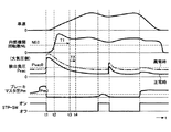
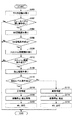
図3は、本実施例の車両20の制御装置22において実現される一例の動作タイムチャートを示す。また、図4は、本実施例の車両20の制御装置22において負圧センサ52の正常異常を判定すべく実行される制御ルーチンの一例のフローチャートを示す。
FIG. 3 shows an example operation time chart realized in the
本実施例のブレーキシステム24において、ブレーキペダル30が踏み込み操作されている状態からその踏み込み操作が解除されてそのブレーキ戻し操作が行われると(図3において時刻t1)、ブレーキブースタ32の負圧室34に大気が導入されることで、負圧室34の負圧が急激に小さくなって大気圧側へ低下する。また、S&S制御による内燃機関26の自動停止中にブレーキペダル30のブレーキ戻し操作が行われると(時刻t1)、上記した所定の再始動条件の成立により内燃機関26が自動始動されることで、内燃機関26の回転上昇が負圧室34の負圧低下に遅れて発生する。内燃機関26が回転すると、ブレーキペダル30のブレーキ操作が無い限り、負圧室34の負圧が大気圧側から直動負圧ポンプ40の作動によりゼロ[kPa]へ向けて徐々に上昇する。
In the
本実施例の制御装置22において、ECU50は、負圧センサ52の正常異常を判定するうえで、その判定を行うタイミングとして、ブレーキブースタ32の負圧室34の負圧がブレーキペダル30のブレーキ操作により消費されるタイミングを排除することとしている。具体的には、まず、ECU50は、予め定められた時間ごとに、マスタ圧センサ56の出力信号に基づいてマスタ圧Pmを読み取り、又は、ストップランプスイッチ58の状態を読み取る(ステップ100)。
In the
ECU50は、上記ステップ100においてデータの読み取りを行った後、運転者によるブレーキペダル30のブレーキ操作が行われていないか否かを判別する(ステップ102)。この判別は、例えば、マスタ圧Pmが所定値Pm0未満であること又はストップランプスイッチ58がオフ状態にある場合に肯定されるものとすればよい。尚、上記した所定値PM0は、ブレーキペダル30のブレーキ操作が行われていない場合に生ずるマスタ圧Pmの最大値に設定されていればよい。
After reading the data in
ECU50は、上記ステップ102においてブレーキペダル30のブレーキ操作が行われていると判別した場合は、以後、何ら処理を進めることなく今回のルーチンを終了する。一方、ブレーキペダル30のブレーキ操作が行われていないと判別した場合は、次に、回転数センサ54の出力信号に基づいて内燃機関26の回転数NEを読み取る(ステップ104)。
If the
ECU50は、上記ステップ104においてデータの読み取りを行った後、内燃機関26の回転条件が成立するか否かを判別する(ステップ106)。この判別は、例えば、内燃機関26の回転数NEが所定閾値NE0以上である状態がその開始から所定時間T1(図3において時刻t2〜t3;例えば5秒や10秒など)以上継続する場合に肯定されるものとすればよい。尚、所定閾値NE0及び所定時間T1はそれぞれ、直動負圧ポンプ40の作動によってブレーキブースタ32の負圧室34に所定レベル以上(具体的には、ゼロ[kPa]近傍)の負圧が生成されると判断される値に設定されていればよい。
After reading the data in step 104, the
ECU50は、上記ステップ106において内燃機関26の回転条件が成立しないと判別した場合は、以後、何ら処理を進めることなく今回のルーチンを終了する。一方、内燃機関26の回転条件が成立すると判別した場合は、次に、負圧センサ52の出力信号に基づいてブレーキブースタ32の負圧室34に生じている負圧Pvacを読み取る(ステップ108)。
If it is determined in
ECU50は、上記ステップ108においてデータの読み取りを行った後、負圧室34の負圧レベルの条件が成立するか否かを判別する(ステップ110)。この判別は、例えば、負圧室34の負圧Pvacが所定負圧Pvac0以上(すなわち、所定負圧Pvac0に比して圧力ゼロ[kPa]側の値)である場合に肯定されるものとすればよい。
After reading the data in
尚、この所定負圧Pvac0は、ブレーキペダル30のブレーキ操作が行われておらずかつ上記した内燃機関26の回転条件が成立した場合に、負圧センサ52が正常状態にあれば取り得る負圧の最小値に設定されていればよい。また、上記した負圧レベルの条件成立有無の判別は、負圧Pvacが所定負圧Pvac0以上である状態が所定時間T2(図3において時刻t3〜t4)以上継続する場合に肯定されるものであってもよい。この場合、所定時間T2は、負圧センサ52の異常時にノイズ等に起因して負圧Pvacが所定負圧Pvac0以上となることで負圧センサ52が正常状態にあると誤判定されるのを排除するためのものであって、予め定められた時間に設定されていればよい。
The predetermined negative pressure Pvac0 is a negative pressure that can be obtained if the
ECU50は、上記ステップ110において負圧Pvacが所定負圧Pvac0未満であってその所定負圧Pvac0に比して大気圧側であることで負圧レベルの条件が成立しないと判別した場合は、負圧センサ52が異常状態(尚、負圧センサ52に偏差異常が生じていることを含む。)にあると判定する(ステップ112)。
If the
ECU50は、また、上記ステップ110において負圧レベルの条件が成立しないと判別した場合は、S&S制御による内燃機関26の自動停止を禁止すると共に(ステップ114)、その負圧センサ52の異常を示すダイアグ記憶を行い、かつ、運転者にその負圧センサ52の異常又は内燃機関26の自動停止禁止を知らせるべくMIL60を点灯表示させる(ステップ116)。尚、負圧センサ52の異常判定に伴う内燃機関26の自動停止の禁止は、内燃機関26の自動停止中に負圧センサ52が異常状態にあると判定された場合に内燃機関26を自動始動させることを含むものである。
If the
また、ECU50は、上記ステップ110において負圧Pvacが所定負圧Pvac0以上であってその所定負圧Pvac0に比して真空圧側であることで負圧レベルの条件が成立すると判別した場合は、負圧センサ52が正常状態にあると判定する(ステップ118)。また、上記ステップ110において負圧レベルの条件が成立すると判別した場合は、S&S制御による内燃機関26の自動停止の禁止を解除すると共に(ステップ120)、運転者への負圧センサ52の異常又は内燃機関26の自動停止禁止の通知を解除すべくMIL60を消灯させる(ステップ122)。
Further, if the
このように、本実施例のS&S制御が実行される車両20の制御装置22においては、ブレーキペダル30がブレーキ操作されておらずかつ内燃機関26の回転数NEが所定閾値NE0以上である状態が所定時間T1以上継続した後のタイミングで、負圧センサ52の出力信号に基づいて検出される負圧室34の負圧Pvacに基づいて、その負圧センサ52の正常異常を判定することができる。
Thus, in the
ブレーキペダル30がブレーキ操作されておらずかつ内燃機関26の回転数NEが所定閾値NE0以上である状態が所定時間T1以上継続した後のタイミングでは、負圧センサ52が正常状態にあれば、その負圧センサ52を用いて検出される負圧室34の負圧Pvacは、所定負圧Pvac0に比して圧力ゼロ[kPa]側の値となる。一方、負圧センサ52が偏差異常を起こしていると、上記のタイミングにおいてその負圧センサ52を用いて検出される負圧室34の負圧Pvacは、所定負圧Pvac0に比して大気圧側の値をとる。
If the
従って、本実施例の制御装置22によれば、上記のタイミングで負圧センサ52を用いて検出される負圧室34の負圧Pvacを所定負圧Pvac0と比較することで、その負圧センサ52の偏差異常を含む異常の有無を判定することができる。また、負圧センサ52の偏差異常が生じているときにその偏差異常が生じていることを負圧センサ52の異常として速やかに検知することができる。このため、本実施例によれば、負圧センサ52の異常を、偏差異常を含めることでより正確に判定することが可能となる。
Therefore, according to the
本実施例においては、上記のタイミングで負圧センサ52を用いて検出される負圧室34の負圧Pvacが所定負圧Pvac0に比して大気圧側の値となり或いは負圧センサ52が異常状態にあると判定されると、以後、S&S制御による内燃機関26の自動停止が禁止される。このため、本実施例によれば、S&S制御により内燃機関26が負圧センサ52の異常時の不必要なタイミングで自動停止されるのを抑制し又はその自動停止が不必要に継続するのを抑制することができるので、その負圧センサ52に異常が生じているときに、内燃機関26の自動停止によって負圧室34の負圧が低下し易くなるのを防止することが可能である。
In this embodiment, the negative pressure Pvac in the
また、本実施例においては、上記の如く負圧センサ52が異常状態にあると判定されると、負圧センサ52の異常がダイアグ記憶される。このため、本実施例によれば、負圧センサ52の異常発生後、車両ディーラーなどで車両20の異常箇所を容易に特定することが可能となる。
In the present embodiment, when it is determined that the
また、本実施例においては、上記の如く負圧センサ52が異常状態にあると判定され或いはS&S制御による内燃機関26の自動停止が禁止されると、以後、負圧センサ52の異常又は内燃機関26の自動停止禁止を知らせるべくMIL60が点灯表示される。このため、本実施例によれば、負圧センサ52の異常時に、その負圧センサ52の異常又はその異常に伴う内燃機関26の自動停止の禁止がMIL60により運転者へ速やかに知らされるので、異常を起こした負圧センサ52の交換ないしは修理を促すことができる。
Further, in this embodiment, when it is determined that the
更に、本実施例においては、一旦、負圧センサ52が異常状態にあると判定された後、その負圧センサ52が正常状態にあると判定された場合は、S&S制御による内燃機関26の自動停止の禁止が解除されると共に、MIL60が消灯される。このため、本実施例によれば、負圧センサ52が異常状態から正常状態へ戻った後は、S&S制御による内燃機関26の自動停止が許容されることで燃費の向上を図ることができると共に、負圧センサ52の無駄な交換や修理などを排除することができる。
Further, in this embodiment, once it is determined that the
尚、上記の実施例においては、ブレーキブースタ32が特許請求の範囲に記載した「ブレーキ操作補助手段」に、所定の停止条件が特許請求の範囲に記載した「第1の条件」に、所定の再始動条件が特許請求の範囲に記載した「第2の条件」に、ECU50がS&S制御を実行することが特許請求の範囲に記載した「自動停止始動手段」に、ECU50が図4に示すルーチン中ステップ102の処理を実行することが特許請求の範囲に記載した「ブレーキ操作有無判別手段」に、ECU50がステップ104の処理を実行することが特許請求の範囲に記載した「回転数検出手段」に、ECU50がステップ108の処理を実行することが特許請求の範囲に記載した「負圧検出手段」に、ECU50がステップ114の処理を実行することが特許請求の範囲に記載した「自動停止禁止手段」に、ECU50がステップ112,118の処理を実行することが特許請求の範囲に記載した「判定手段」に、ECU50がステップ116の処理を実行することが特許請求の範囲に記載した「負圧センサ異常通知手段」、「自動停止禁止通知手段」、及び「表示手段」に、それぞれ相当している。
In the above embodiment, the
ところで、上記の実施例においては、内燃機関26の回転条件が成立するか否かを判別するのに、内燃機関26の回転数NEの所定閾値NE0及び所定時間T1を用いることとしているが、これらの所定閾値NE0及び所定時間T1は共に固定値であってもよい。また、直動負圧ポンプ40の負圧生成能力は、内燃機関26の回転数NEに応じて変わるので、所定閾値NE0は固定値である一方で、所定時間T1は図5に示す如く内燃機関26の回転数NEに応じて変更されるものであってもよい。かかる変形例によれば、直動負圧ポンプ40の負圧生成能力が変化しても、負圧センサ52の正常異常を判定するうえで用いるパラメータとしての負圧Pvacの検出を、負圧室34に生成されている負圧が常にゼロ[kPa]近傍に達するタイミングで開始することができるので、負圧センサ52の正常異常の判定を精度よく行うことが可能となる。
In the above embodiment, the predetermined threshold value NE0 and the predetermined time T1 of the rotational speed NE of the
また、上記の実施例においては、上記ステップ102において運転者によるブレーキペダル30のブレーキ操作が行われていないか否かの判別を、マスタ圧Pmが所定値Pm0未満であるか否か又はストップランプスイッチ58がオフ状態にあるか否かに基づいて行うこととしている。しかし、本発明はこれに限定されるものではなく、上記ステップ102における判別を、マスタ圧Pmの、内燃機関26の回転が開始されたタイミングでの値と負圧センサ52を用いて負圧Pvacが検出されるタイミングでの値との差圧の絶対値が所定値未満であるか否か、又は、ストップランプスイッチ58がオフ状態にあるか否かに基づいて行うこととしてもよい。この場合、この判別は、差圧絶対値が所定値未満であること又はストップランプスイッチ58がオフ状態にある場合に肯定される。尚、かかる変形例において、差圧絶対値の所定値は、ブレーキペダル30のブレーキ操作が行われていないと判断される上記の差圧の最大値に設定されていればよい。この場合には、ECU50がかかる判別を行うことが特許請求の範囲に記載した「ブレーキ操作有無判別手段」及び「ブレーキ踏み込み操作有無判別手段」に相当する。
In the above embodiment, it is determined whether or not the brake operation of the
また、上記ステップ102における判別を、マスタ圧Pmの、内燃機関26の回転が開始されたタイミングでの値から負圧センサ52を用いて負圧が検出されるタイミングでの値を差し引いた差圧がゼロ以上かつ所定値未満であるか否か、又は、ストップランプスイッチ58がオフ状態にあるか否かに基づいて行うこととしてもよい。この場合、この判別は、差圧がゼロ以上かつ所定値未満であること又はストップランプスイッチ58がオフ状態にある場合に肯定される。尚、かかる変形例において、差圧の所定値は、ブレーキペダル30のブレーキ操作が行われていないと判断される上記の差圧の最大値に設定されていればよい。この場合には、ECU50がかかる判別を行うことが特許請求の範囲に記載した「ブレーキ操作有無判別手段」及び「ブレーキ踏み込み操作有無判別手段」に相当する。
Further, the determination in step 102 is performed by subtracting the value at the timing at which the negative pressure is detected using the
また、上記ステップ102における判別を、マスタ圧Pmの、内燃機関26の回転が開始されたタイミングでの値から負圧センサ52を用いて負圧が検出されるタイミングでの値を差し引いた差圧が所定値以上であるか否か、又は、ストップランプスイッチ58がオン状態からオフ状態へ切り替わったか否かに基づいて行うこととしてもよい。この場合、この判別は、差圧が所定値以上であること又はストップランプスイッチ58がオン状態からオフ状態へ切り替わった場合に肯定される。この場合には、ECU50がかかる判別を行うことが特許請求の範囲に記載した「ブレーキ操作有無判別手段」及び「ブレーキ戻し操作有無判別手段」に相当する。
Further, the determination in step 102 is performed by subtracting the value at the timing at which the negative pressure is detected using the
上記の実施例においては、ブレーキシステム24に内燃機関26の回転に応じて作動する直動負圧ポンプ40を設けたうえで、ECU50にステップ106において内燃機関26の回転条件が成立するか否かの判別を実施させることとしている。しかし、本発明はこれに限定されるものではなく、直動負圧ポンプ40が設けられていないブレーキシステム24に適用することが可能である。直動負圧ポンプ40が設けられていないブレーキシステム24においては、負圧室34に十分な負圧が生成されるタイミングは、内燃機関26の回転のみに依存せず、内燃機関26が有するスロットルの開度にも依存する。そこで、ECU50に以下に示す如く内燃機関26の回転条件が成立するか否かの判別を実施させることとしてもよい。
In the above embodiment, the
すなわち、かかる変形例において、ECU50は、図7に示す如く、マスタ圧センサ56の出力信号に基づいてマスタ圧Pmを読み取り(ステップ200)、その後、運転者によるブレーキペダル30のブレーキ戻し操作が行われていないか否かを判別する(ステップ202)。この判別は、例えば、マスタ圧Pmの減少量が所定値以下である場合に肯定されるものとすればよい。尚、上記した所定値は、ブレーキペダル30のブレーキ戻し操作が行われていない場合に生ずるマスタ圧Pmの減少量の最大値に設定されていればよい。
That is, in such a modification, the
ECU50は、上記ステップ202においてブレーキペダル30のブレーキ戻し操作が行われていると判別した場合は、以後、何ら処理を進めることなく今回のルーチンを終了する。一方、ブレーキペダル30のブレーキ戻し操作が行われていないと判別した場合は、次に、回転数センサ54の出力信号に基づいて内燃機関26の回転数NEを読み取り(ステップ204)、その後、内燃機関26の回転条件が成立するか否かを判別する(ステップ206)。この判別は、例えば、内燃機関26の回転数NEが所定閾値(上記の実施例の所定閾値NE0と同じであってもよい。)以上である状態が所定時間(上記の実施例の所定時間T1と同じであってもよい。)以上継続する場合に肯定されるものとすればよい。
If it is determined in step 202 that the brake return operation of the
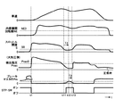
ECU50は、上記ステップ106において内燃機関26の回転条件が成立しないと判別した場合は、以後、何ら処理を進めることなく今回のルーチンを終了する。一方、内燃機関26の回転条件が成立すると判別した場合は、次に、内燃機関26が有するスロットルの開度に応じた信号を出力するスロットル開度センサの出力信号に基づいてスロットル開度Sを読み取り(ステップ208)、その後、スロットル開度Sの条件が成立するか否かを判別する(ステップ210)。この判別は、例えば、スロットル開度Sが所定開度S0以下である状態が所定時間T3(図6において時刻t11〜t12)以上継続する場合に肯定されるものとすればよい。尚、所定開度S0及び所定時間T3はそれぞれ、内燃機関26の回転によってブレーキブースタ32の負圧室34に所定レベル以上(具体的には、ゼロ[kPa]近傍)の負圧が生成されると判断される値に設定されていればよい。
If it is determined in
ECU50は、上記ステップ210においてスロットル開度Sの条件が成立しないと判別した場合は、以後、何ら処理を進めることなく今回のルーチンを終了する。一方、スロットル開度Sの条件が成立すると判別した場合は、図7に示す如く、図4に示すステップ108以降の処理と同様の処理を実行する。尚、上記ステップ110における負圧レベルの条件成立有無の判別は、負圧Pvacが所定負圧Pvac0以上である状態が所定時間T2(図6において時刻t12〜t13)以上継続する場合に肯定されるものであってもよい。そして、負圧Pvacが所定負圧Pvac0以上であると判別した場合は、負圧センサ52が正常状態にあると判定し、一方、負圧Pvacが所定負圧Pvac0未満であってその所定負圧Pvac0に比して大気圧側であると判別した場合は、負圧センサ52が異常状態にあると判定する。
If the
ブレーキペダル30のブレーキ戻し操作が行われておらず、内燃機関26の所定閾値以上の回転数NEが所定時間以上継続し、かつ、所定開度S0以下のスロットル開度Sが所定時間T3以上継続した後のタイミングでは、いわゆるポンピングロスが十分に発生し、ブレーキブースタ32の負圧室34に十分な負圧が生成される。従って、かかる変形例の如く、ブレーキシステム24に直動負圧ポンプ40が設けられていない構成でも、そのタイミングで負圧センサ52の出力信号に基づいて検出される負圧室34の負圧Pvacに基づいて、その負圧センサ52の正常異常を判定することができ、上記の実施例と同様の効果を得ることができる。
The brake return operation of the
また、上記の実施例においては、ブレーキブースタ32の負圧室34に負圧管38を介して内燃機関26や直動負圧ポンプ40を接続するものとし、その負圧室34に内燃機関26の回転に応じた負圧を導くものとしている。しかし、本発明はこれに限定されるものではなく、負圧室34に負圧管38を介して電動バキュームポンプを接続するものとし、その負圧室34に内燃機関26の回転に関係なく電力供給により作動する電動バキュームポンプの作動により負圧を導くものとしてもよい。この電動バキュームポンプは、S&S制御中を含めて車両20の起動中、作動されるものであってもよい。
In the above embodiment, the
例えば、図8に示す如く、ECU50は、運転者によるブレーキペダル30のブレーキ操作が行われておらずかつ電動バキュームポンプが作動している状態が所定時間以上継続するか否かを判別する(ステップ300)。尚、この所定時間は、電動バキュームポンプの作動によってブレーキブースタ32の負圧室34に所定レベル以上(具体的には、ゼロ[kPa]近傍)の負圧が生成されると判断される値に設定されていればよい。そして、ECU50は、ブレーキペダル30のブレーキ操作が行われておらずかつ電動バキュームポンプが作動している状態が所定時間以上継続したと判別した場合に、次に、負圧センサ52の出力信号に基づいて検出される負圧室34の負圧Pvacが予め定められた正常範囲から外れているか否かを判別する(ステップ302)。その結果、負圧Pvacが正常範囲から外れていると判別した場合に、負圧センサ52が異常状態(尚、負圧センサ52に偏差異常が生じていることを含む。)にあると判定する(ステップ304)。
For example, as shown in FIG. 8, the
ブレーキペダル30がブレーキ操作されておらずかつ電動バキュームポンプが作動している状態が所定時間以上継続した後のタイミングでは、負圧センサ52が正常状態にあれば、その負圧センサ52を用いて検出される負圧室34の負圧Pvacは、所定負圧Pvac0に比して圧力ゼロ[kPa]側の値となる。一方、負圧センサ52が偏差異常を起こしていると、上記のタイミングにおいてその負圧センサ52を用いて検出される負圧室34の負圧Pvacは、所定負圧Pvac0に比して大気圧側の値をとる。
If the
従って、かかる変形例においても、上記した実施例と同様に、負圧センサ52の偏差異常を含む異常の有無を判定することができると共に、その偏差異常が生じているときにその偏差異常が生じていることを負圧センサ52の異常として速やかに検知することができる。また、内燃機関26の回転に関係なく電動バキュームポンプの作動により負圧室34に負圧を導くことができるので、負圧センサ52の異常の有無を判定する機会を増やすことができ、これによっても、負圧センサ52の異常が生じていることを速やかに判定することができる。
Accordingly, also in such a modified example, it is possible to determine the presence / absence of an abnormality including a deviation abnormality of the
尚、この変形例においては、負圧センサ52が異常状態にあるとの判定を、負圧Pvacが正常範囲から外れる状態が所定時間以上継続する場合に肯定するものであってもよい。また、上記の変形例においても、上記の実施例と同様に、負圧センサ52が異常状態にあるとの判定だけでなく、負圧センサ52が正常状態にあるとの判定を行うこととしてもよい。また、負圧センサ52が異常状態にあるとの判定を負圧Pvacが正常範囲から外れる状態が所定時間以上継続する場合に肯定すると共に、負圧センサ52が正常状態にあるとの判定を負圧Pvacが正常範囲内にある状態が所定時間以上継続する場合に肯定する構成では、負圧Pvacが正常範囲から外れる状態又は負圧Pvacが正常範囲内にある状態が所定時間以上継続する前に、それらの状態が交互に発生するようなときは、判定精度の向上のため又は誤判定防止のため、状態の継続時間をリセットすることとしてもよい。
In this modification, the determination that the
また、上記の変形例においては、電動バキュームポンプを意図的に作動させて、条件成立後に検出される負圧室34の負圧Pvacに基づいて負圧センサ52の異常有無を判定させることとしてもよい。この場合は、負圧センサ52の異常有無を判定する機会を強制的に増やすことが可能となる。尚、この場合、電動バキュームポンプを意図的に作動させるタイミングを、ブレーキペダル30のブレーキ操作が行われないと予想される時に限定するものであってもよい。例えば、アクセルペダル操作と車速とを検知し、アクセルペダルが踏み込まれかつ車両が加速している時は、ブレーキペダル30が操作され難いと判断し、電動バキュームポンプを意図的に作動させることとしてもよい。また、S&S制御による内燃機関26の自動停止中は、オルタネータが作動せずその発電が行われないので、電力消費を抑えるために電動バキュームポンプの意図的な作動を行わないこととしてもよい。更に、車速や減速度などの車両状態に基づいて、S&S制御による内燃機関26の自動停止の実行条件が成立することを事前に予測し、内燃機関26の自動停止前に電動バキュームポンプを意図的に作動させて、負圧センサ52の異常有無を判定させることとしてもよい。
In the above modification, the electric vacuum pump is intentionally operated to determine whether the
また、上記の実施例においては、負圧センサ52の正常異常の判定を、検出される負圧室34の負圧Pvacが所定負圧Pvac0以上であるか否かに基づいて行うこととしているが、この所定負圧Pvac0は固定値であってもよい。また、内燃機関の回転による負圧生成能力は、車両20が置かれている環境での大気圧、及び、S&S制御による内燃機関26の自動停止中でのブレーキ力確保に必要な負圧値に応じて変わるので、上記の所定負圧Pvac0は、それらの大気圧や必要負圧に応じて変更されるものであってもよい。かかる変形例によれば、負圧センサ52の正常異常の判定を精度よく行うことが可能となり、その結果として、S&S制御による内燃機関26の自動停止の禁止を精度良く行うことができる。この場合には、ECU50が所定負圧Pvac0を変更することが特許請求の範囲に記載した「閾値変更手段」に相当する。
In the above embodiment, whether the
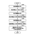
例えば、ECU50は、所定負圧Pvac0を設定するうえで、図9に示す如く、まず、大気圧αを算出すると共に、S&S制御による内燃機関26の自動停止中に車両停車のためのブレーキ力を確保するために必要な必要負圧βを算出する(ステップ400)。そして、その算出した大気圧α及び必要負圧β、並びに、予め定められた負圧センサ52ごとの特性バラツキ誤差を吸収するための誤差マージンγに基づいて、所定負圧Pvac0を設定する(ステップ402)。具体的には、大気圧αから必要負圧βを差し引きかつ誤差マージンγを差し引いた値を所定負圧Pvac0として設定する(Pvac0=α−β―γ)。ECU50は、その設定後の所定負圧Pvac0を用いて上記ステップ110の処理を実行する。
For example, when setting the predetermined negative pressure Pvac0, the
尚、上記ステップ400における大気圧αは、予め定められた固定値を用いるものであってもよい。また、大気圧αは、高度として予め定められた固定値を用いる一方で、その高度固定値を気圧情報、温度情報などに基づいて補正した値を用いるものであってもよい。更に、大気圧αは、車両20が現在置かれている高度情報、気圧情報、温度情報などに基づいて算出されるものであってもよい。
Note that the atmospheric pressure α in
例えば、ECU50は、上記ステップ400において大気圧αを算出するうえで、図10に示す如く、まず、ナビゲーションシステムや高度計などを用いて検出される車両20が走行する現位置での高度情報を読み取り(ステップ500)、その読み取った高度情報から、予め定められた高度と大気圧xとの関係を規定した図11(A)に示す如きマップを参照して、大気圧xを算出する(ステップ502)。この場合、大気圧xは、高高度ほど低くなり、低高度ほど高くなる。
For example, in calculating the atmospheric pressure α in the
次に、ECU50は、気象情報端末や気圧センサなどを用いて車両20が走行する現位置での気圧情報を読み取り(ステップ504)、その読み取った気圧情報から、予め定められた気圧と大気圧補正値Ψとの関係を規定した図11(B)に示す如きマップを参照して、通常値との差分を示す大気圧補正値Ψを算出する(ステップ506)。この場合、大気圧補正値Ψは、低気圧ほど通常値よりも下げる値であり、高気圧ほど通常値よりも上げる値である。
Next, the
次に、ECU50は、温度センサなどを用いて温度情報を読み取り(ステップ508)、その読み取った温度情報から、予め定められた温度と大気圧補正値ωとの関係を規定した図11(C)に示す如きマップを参照して、通常値との差分を示す大気圧補正値ωを算出する(ステップ510)。この場合、大気圧補正値ωは、高温ほど通常値よりも下げる値であり、低温ほど通常値よりも上げる値である。そして、ECU50は、上記の如く算出した大気圧x、大気圧補正値Ψ、及び大気圧補正値ωに基づいて、大気圧αを算出する(ステップ512;α=x+Ψ+ω)。
Next, the
尚、上記ステップ400における必要負圧βは、予め定められた固定値を用いるものであってもよい。また、必要負圧βは、車両20が現在置かれている状態や周辺環境などに基づいて算出される車両20の制動に必要な負圧値、又は、車両20の特徴に基づいて算出される車両20の制動に必要な負圧値を用いて算出されるものであってもよい。
The necessary negative pressure β in
例えば、ECU50は、上記ステップ400において必要負圧βを算出するうえで、図12に示す如く、まず、ナビゲーションシステムや傾斜センサなどを用いて検出される車両20が現在置かれている道路路面の勾配情報を読み取り(ステップ600)、その読み取った勾配情報から、予め定められた勾配と必要負圧ηとの関係を規定した図13(A)に示す如きマップを参照して、必要負圧ηを算出する(ステップ602)。この場合、必要負圧ηは、勾配がゼロに近いほど小さくなり、勾配が大きいほど大きくなる。
For example, the
次に、ECU50は、車重や車格,搭載エンジンの排気量,搭載ブレーキシステムなどの予め定められた車両情報を読み取り(ステップ604)、その読み取った車両情報から、車両情報(ここでは、具体的に「車重」を示す。)と必要負圧θとの関係を規定した図13(B)に示す如きマップを参照して、必要負圧θを算出する(ステップ606)。この場合、必要負圧θは、車重やエンジン排気量が小さいほど小さくなり、車重やエンジン排気量が大きいほど大きくなる。また、そして、ECU50は、上記の如く算出した必要負圧η,θに基づいて、必要負圧βを算出する(ステップ608;β=η+θ)。
Next, the
更に、上記の実施例においては、負圧センサ52の異常又は内燃機関26の自動停止の禁止を運転者に知らせる手段として、メータ内に設けられる表示ランプであるMIL60を用いることとしている。しかし、本発明はこれに限定されるものではなく、他の表示手段を用いることとしてもよいし、また、視覚による手段に代えて或いは視覚による手段と共に聴覚による手段を用いることとしてもよい。
Further, in the above embodiment, the
20 車両
22 制御装置
24 ブレーキシステム
26 内燃機関
30 ブレーキペダル
32 ブレーキブースタ
34 負圧室
40 直動負圧ポンプ
44 マスタシリンダ
50 電子制御ユニット(ECU)
52 負圧センサ
54 回転数センサ
56 マスタ圧センサ
58 ストップランプスイッチ
60 表示ランプ(MIL)
DESCRIPTION OF
52
Claims (11)
車両運転者によるブレーキ操作が行われていないか否かを判別するブレーキ操作有無判別手段と、
前記内燃機関の回転数を検出する回転数検出手段と、
前記負圧室に生ずる負圧を検出する負圧検出手段と、
前記ブレーキ操作有無判別手段により前記ブレーキ操作が行われていないと判別されかつ前記回転数検出手段により検出される前記内燃機関の回転数が閾値以上である状態が所定時間以上継続した後、前記負圧検出手段により検出される前記負圧室の負圧に基づいて、前記自動停止始動手段による前記内燃機関の自動停止を禁止する自動停止禁止手段と、
を備えることを特徴とする車両の制御装置。 A negative pressure chamber in which a negative pressure is generated in accordance with the rotation of the internal combustion engine; a brake operation assisting means for assisting a driver in braking using the negative pressure in the negative pressure chamber; and when the first condition is satisfied, An automatic stop / starting means for automatically stopping the internal combustion engine and automatically starting the internal combustion engine when the second condition is satisfied after the automatic stop;
Brake operation presence / absence determining means for determining whether or not a brake operation is not performed by a vehicle driver;
A rotational speed detection means for detecting the rotational speed of the internal combustion engine;
Negative pressure detecting means for detecting negative pressure generated in the negative pressure chamber;
After the brake operation presence / absence determining means determines that the brake operation has not been performed and the engine speed detected by the engine speed detection means is equal to or greater than a threshold value for a predetermined time or more, the negative Automatic stop prohibiting means for prohibiting automatic stop of the internal combustion engine by the automatic stop starting means based on the negative pressure of the negative pressure chamber detected by the pressure detecting means;
A vehicle control apparatus comprising:
前記ブレーキ操作有無判別手段により前記ブレーキ操作が行われていないと判別されかつ前記回転数検出手段により検出される前記内燃機関の回転数が前記閾値以上である状態が前記所定時間以上継続した後、前記負圧検出手段により検出される前記負圧室の負圧に基づいて、前記負圧センサが異常状態にあるか否かを判定する判定手段を備えることを特徴とする請求項1乃至4の何れか一項記載の車両の制御装置。 The negative pressure detecting means detects the negative pressure in the negative pressure chamber based on an output signal of a negative pressure sensor that outputs a signal corresponding to the negative pressure generated in the negative pressure chamber,
After the brake operation presence / absence determining means determines that the brake operation is not performed and the state where the rotation speed of the internal combustion engine detected by the rotation speed detection means is equal to or greater than the threshold value continues for the predetermined time, 5. The apparatus according to claim 1, further comprising: a determination unit that determines whether the negative pressure sensor is in an abnormal state based on a negative pressure of the negative pressure chamber detected by the negative pressure detection unit. The vehicle control device according to claim 1.
Priority Applications (3)
| Application Number | Priority Date | Filing Date | Title |
|---|---|---|---|
| JP2014120865A JP2016000972A (en) | 2014-06-11 | 2014-06-11 | Vehicle control device |
| PCT/IB2015/000863 WO2015189673A1 (en) | 2014-06-11 | 2015-06-08 | Vehicle control apparatus |
| US15/316,752 US20170191458A1 (en) | 2014-06-11 | 2015-06-08 | Vehicle control apparatus |
Applications Claiming Priority (1)
| Application Number | Priority Date | Filing Date | Title |
|---|---|---|---|
| JP2014120865A JP2016000972A (en) | 2014-06-11 | 2014-06-11 | Vehicle control device |
Publications (2)
| Publication Number | Publication Date |
|---|---|
| JP2016000972A true JP2016000972A (en) | 2016-01-07 |
| JP2016000972A5 JP2016000972A5 (en) | 2016-10-06 |
Family
ID=53496897
Family Applications (1)
| Application Number | Title | Priority Date | Filing Date |
|---|---|---|---|
| JP2014120865A Pending JP2016000972A (en) | 2014-06-11 | 2014-06-11 | Vehicle control device |
Country Status (3)
| Country | Link |
|---|---|
| US (1) | US20170191458A1 (en) |
| JP (1) | JP2016000972A (en) |
| WO (1) | WO2015189673A1 (en) |
Cited By (7)
| Publication number | Priority date | Publication date | Assignee | Title |
|---|---|---|---|---|
| US9527492B2 (en) | 2014-12-26 | 2016-12-27 | Toyota Jidosha Kabushiki Kaisha | Negative pressure sensor abnormality detection apparatus, control apparatus for internal combustion engine and control system |
| US9665996B2 (en) | 2014-12-15 | 2017-05-30 | Toyota Jidosha Kabushiki Kaisha | Negative pressure abnormality detection apparatus and control apparatus for internal combustion engine |
| JP2017149395A (en) * | 2016-02-26 | 2017-08-31 | ダイハツ工業株式会社 | Vehicular control device |
| US9945341B2 (en) | 2014-12-15 | 2018-04-17 | Toyota Jidosha Kabushiki Kaisha | Negative pressure abnormality detection apparatus, and control apparatus for internal combustion engine |
| CN108045372A (en) * | 2017-11-13 | 2018-05-18 | 潍柴动力股份有限公司 | The engine on-off control method and control system of hybrid electric vehicle |
| JP2019015202A (en) * | 2017-07-05 | 2019-01-31 | トヨタ自動車株式会社 | Controller of cooling system of internal combustion engine |
| JP2020056613A (en) * | 2018-09-28 | 2020-04-09 | 旭化成株式会社 | Humidity measurement device and dew-point temperature measurement device |
Families Citing this family (4)
| Publication number | Priority date | Publication date | Assignee | Title |
|---|---|---|---|---|
| US11220990B2 (en) * | 2019-11-29 | 2022-01-11 | Hyundai Motor Company | Method and device for controlling start of vehicle |
| FR3108079A1 (en) * | 2020-03-10 | 2021-09-17 | Psa Automobiles Sa | PROCESS FOR CONTROL OF AN ELECTRIC VACUUM PUMP IN A VACUUM BRAKING SYSTEM FOR A VEHICLE |
| CN111591297B (en) * | 2020-05-29 | 2023-03-28 | 重庆长安新能源汽车科技有限公司 | Altitude estimation method and device for environment where pure electric vehicle is located and pure electric vehicle |
| CN115214581B (en) * | 2022-05-18 | 2023-07-25 | 广州汽车集团股份有限公司 | Control method and device, vehicle and storage medium |
Citations (2)
| Publication number | Priority date | Publication date | Assignee | Title |
|---|---|---|---|---|
| JP2000344093A (en) * | 1999-03-26 | 2000-12-12 | Toyota Motor Corp | Device for detecting abnormality of brake boost pressure sensor system of vehicle |
| JP2012214185A (en) * | 2011-04-01 | 2012-11-08 | Honda Motor Co Ltd | Negative pressure system |
Family Cites Families (10)
| Publication number | Priority date | Publication date | Assignee | Title |
|---|---|---|---|---|
| JP3723001B2 (en) * | 1998-12-02 | 2005-12-07 | トヨタ自動車株式会社 | Brake booster negative pressure drop determination device |
| JP2000337190A (en) * | 1999-03-25 | 2000-12-05 | Toyota Motor Corp | Control device of vehicular engine automatic stop |
| JP2001140672A (en) * | 1999-11-15 | 2001-05-22 | Denso Corp | Automatic stopping/starting device for engine |
| JP2003020968A (en) * | 2001-07-10 | 2003-01-24 | Toyota Motor Corp | Automatic stop control device of internal combustion engine |
| JP5333157B2 (en) * | 2009-11-04 | 2013-11-06 | 株式会社デンソー | Vehicle control system |
| JP2011122519A (en) | 2009-12-10 | 2011-06-23 | Fujitsu Ten Ltd | Engine automatic stop restart control device and method |
| JP6133818B2 (en) * | 2014-06-11 | 2017-05-24 | トヨタ自動車株式会社 | Vehicle control device |
| JP6135655B2 (en) * | 2014-12-15 | 2017-05-31 | トヨタ自動車株式会社 | Negative pressure abnormality detection device and control device for internal combustion engine |
| JP6123783B2 (en) * | 2014-12-15 | 2017-05-10 | トヨタ自動車株式会社 | Negative pressure abnormality detection device and control device for internal combustion engine |
| JP6115560B2 (en) * | 2014-12-26 | 2017-04-19 | トヨタ自動車株式会社 | Negative pressure sensor abnormality detection device and control device for internal combustion engine |
-
2014
- 2014-06-11 JP JP2014120865A patent/JP2016000972A/en active Pending
-
2015
- 2015-06-08 US US15/316,752 patent/US20170191458A1/en not_active Abandoned
- 2015-06-08 WO PCT/IB2015/000863 patent/WO2015189673A1/en active Application Filing
Patent Citations (2)
| Publication number | Priority date | Publication date | Assignee | Title |
|---|---|---|---|---|
| JP2000344093A (en) * | 1999-03-26 | 2000-12-12 | Toyota Motor Corp | Device for detecting abnormality of brake boost pressure sensor system of vehicle |
| JP2012214185A (en) * | 2011-04-01 | 2012-11-08 | Honda Motor Co Ltd | Negative pressure system |
Cited By (9)
| Publication number | Priority date | Publication date | Assignee | Title |
|---|---|---|---|---|
| US9665996B2 (en) | 2014-12-15 | 2017-05-30 | Toyota Jidosha Kabushiki Kaisha | Negative pressure abnormality detection apparatus and control apparatus for internal combustion engine |
| US9945341B2 (en) | 2014-12-15 | 2018-04-17 | Toyota Jidosha Kabushiki Kaisha | Negative pressure abnormality detection apparatus, and control apparatus for internal combustion engine |
| US9527492B2 (en) | 2014-12-26 | 2016-12-27 | Toyota Jidosha Kabushiki Kaisha | Negative pressure sensor abnormality detection apparatus, control apparatus for internal combustion engine and control system |
| JP2017149395A (en) * | 2016-02-26 | 2017-08-31 | ダイハツ工業株式会社 | Vehicular control device |
| JP2019015202A (en) * | 2017-07-05 | 2019-01-31 | トヨタ自動車株式会社 | Controller of cooling system of internal combustion engine |
| US10927747B2 (en) | 2017-07-05 | 2021-02-23 | Toyota Jidosha Kabushiki Kaisha | Controller for cooling system of internal combustion engine |
| CN108045372A (en) * | 2017-11-13 | 2018-05-18 | 潍柴动力股份有限公司 | The engine on-off control method and control system of hybrid electric vehicle |
| JP2020056613A (en) * | 2018-09-28 | 2020-04-09 | 旭化成株式会社 | Humidity measurement device and dew-point temperature measurement device |
| US11820333B2 (en) | 2018-09-28 | 2023-11-21 | Asahi Kasei Kabushiki Kaisha | Humidity measuring device and dew point temperature measuring device |
Also Published As
| Publication number | Publication date |
|---|---|
| US20170191458A1 (en) | 2017-07-06 |
| WO2015189673A1 (en) | 2015-12-17 |
Similar Documents
| Publication | Publication Date | Title |
|---|---|---|
| JP2016000972A (en) | Vehicle control device | |
| JP6115560B2 (en) | Negative pressure sensor abnormality detection device and control device for internal combustion engine | |
| JP6135655B2 (en) | Negative pressure abnormality detection device and control device for internal combustion engine | |
| JP6133818B2 (en) | Vehicle control device | |
| JP6123783B2 (en) | Negative pressure abnormality detection device and control device for internal combustion engine | |
| US8566007B2 (en) | Automatic stop/restart device for internal combustion engine | |
| RU2576642C2 (en) | Engine automatic shutoff and start | |
| US10696287B2 (en) | Initiating preparations for engine autostop prior to vehicle stop | |
| JP2009243452A (en) | Vehicle failure diagnosis apparatus | |
| JP5476333B2 (en) | Negative pressure system | |
| US9404437B2 (en) | Engine control apparatus performing automatic engine restart for ensuring brake booster assistance after automatic engine stop | |
| JP6179440B2 (en) | Vehicle control device | |
| US20100222991A1 (en) | Method for operating an internal combustion engine | |
| JP5382260B1 (en) | ENGINE RESTART CONTROL DEVICE, VEHICLE, AND VEHICLE CONTROL METHOD | |
| JP2014070531A (en) | Control device for vehicle | |
| JP2010071205A (en) | Control device of internal combustion engine | |
| JP2009097347A (en) | Device for controlling internal combustion engine | |
| KR102621530B1 (en) | System and method for controlling motor driven power steering | |
| JP2006057525A (en) | Starter failure detecting device | |
| JP7435019B2 (en) | Control device | |
| JP2018080638A (en) | Engine restarting device | |
| JP2015137561A (en) | Driving apparatus | |
| JP2016050529A (en) | Control device for internal combustion engine | |
| JP2008068746A (en) | Negative pressure system of vehicle | |
| JP2018189045A (en) | Control device of vehicle |
Legal Events
| Date | Code | Title | Description |
|---|---|---|---|
| A521 | Request for written amendment filed |
Free format text: JAPANESE INTERMEDIATE CODE: A523 Effective date: 20160823 |
|
| A621 | Written request for application examination |
Free format text: JAPANESE INTERMEDIATE CODE: A621 Effective date: 20160823 |
|
| A977 | Report on retrieval |
Free format text: JAPANESE INTERMEDIATE CODE: A971007 Effective date: 20170519 |
|
| A131 | Notification of reasons for refusal |
Free format text: JAPANESE INTERMEDIATE CODE: A131 Effective date: 20170606 |
|
| A02 | Decision of refusal |
Free format text: JAPANESE INTERMEDIATE CODE: A02 Effective date: 20171205 |