JP6179440B2 - Vehicle control device - Google Patents
Vehicle control device Download PDFInfo
- Publication number
- JP6179440B2 JP6179440B2 JP2014070431A JP2014070431A JP6179440B2 JP 6179440 B2 JP6179440 B2 JP 6179440B2 JP 2014070431 A JP2014070431 A JP 2014070431A JP 2014070431 A JP2014070431 A JP 2014070431A JP 6179440 B2 JP6179440 B2 JP 6179440B2
- Authority
- JP
- Japan
- Prior art keywords
- battery
- value
- stop
- predetermined
- deceleration
- Prior art date
- Legal status (The legal status is an assumption and is not a legal conclusion. Google has not performed a legal analysis and makes no representation as to the accuracy of the status listed.)
- Active
Links
Images


Classifications
-
- G—PHYSICS
- G01—MEASURING; TESTING
- G01R—MEASURING ELECTRIC VARIABLES; MEASURING MAGNETIC VARIABLES
- G01R31/00—Arrangements for testing electric properties; Arrangements for locating electric faults; Arrangements for electrical testing characterised by what is being tested not provided for elsewhere
- G01R31/50—Testing of electric apparatus, lines, cables or components for short-circuits, continuity, leakage current or incorrect line connections
- G01R31/54—Testing for continuity
-
- F—MECHANICAL ENGINEERING; LIGHTING; HEATING; WEAPONS; BLASTING
- F02—COMBUSTION ENGINES; HOT-GAS OR COMBUSTION-PRODUCT ENGINE PLANTS
- F02D—CONTROLLING COMBUSTION ENGINES
- F02D41/00—Electrical control of supply of combustible mixture or its constituents
- F02D41/02—Circuit arrangements for generating control signals
- F02D41/04—Introducing corrections for particular operating conditions
- F02D41/042—Introducing corrections for particular operating conditions for stopping the engine
-
- F—MECHANICAL ENGINEERING; LIGHTING; HEATING; WEAPONS; BLASTING
- F02—COMBUSTION ENGINES; HOT-GAS OR COMBUSTION-PRODUCT ENGINE PLANTS
- F02D—CONTROLLING COMBUSTION ENGINES
- F02D41/00—Electrical control of supply of combustible mixture or its constituents
- F02D41/02—Circuit arrangements for generating control signals
- F02D41/04—Introducing corrections for particular operating conditions
- F02D41/06—Introducing corrections for particular operating conditions for engine starting or warming up
- F02D41/062—Introducing corrections for particular operating conditions for engine starting or warming up for starting
- F02D41/065—Introducing corrections for particular operating conditions for engine starting or warming up for starting at hot start or restart
-
- F—MECHANICAL ENGINEERING; LIGHTING; HEATING; WEAPONS; BLASTING
- F02—COMBUSTION ENGINES; HOT-GAS OR COMBUSTION-PRODUCT ENGINE PLANTS
- F02D—CONTROLLING COMBUSTION ENGINES
- F02D41/00—Electrical control of supply of combustible mixture or its constituents
- F02D41/02—Circuit arrangements for generating control signals
- F02D41/04—Introducing corrections for particular operating conditions
- F02D41/08—Introducing corrections for particular operating conditions for idling
-
- F—MECHANICAL ENGINEERING; LIGHTING; HEATING; WEAPONS; BLASTING
- F02—COMBUSTION ENGINES; HOT-GAS OR COMBUSTION-PRODUCT ENGINE PLANTS
- F02D—CONTROLLING COMBUSTION ENGINES
- F02D41/00—Electrical control of supply of combustible mixture or its constituents
- F02D41/24—Electrical control of supply of combustible mixture or its constituents characterised by the use of digital means
- F02D41/26—Electrical control of supply of combustible mixture or its constituents characterised by the use of digital means using computer, e.g. microprocessor
-
- F—MECHANICAL ENGINEERING; LIGHTING; HEATING; WEAPONS; BLASTING
- F02—COMBUSTION ENGINES; HOT-GAS OR COMBUSTION-PRODUCT ENGINE PLANTS
- F02N—STARTING OF COMBUSTION ENGINES; STARTING AIDS FOR SUCH ENGINES, NOT OTHERWISE PROVIDED FOR
- F02N11/00—Starting of engines by means of electric motors
- F02N11/08—Circuits or control means specially adapted for starting of engines
- F02N11/0814—Circuits or control means specially adapted for starting of engines comprising means for controlling automatic idle-start-stop
- F02N11/0818—Conditions for starting or stopping the engine or for deactivating the idle-start-stop mode
- F02N11/0825—Conditions for starting or stopping the engine or for deactivating the idle-start-stop mode related to prevention of engine restart failure, e.g. disabling automatic stop at low battery state
-
- G—PHYSICS
- G01—MEASURING; TESTING
- G01R—MEASURING ELECTRIC VARIABLES; MEASURING MAGNETIC VARIABLES
- G01R31/00—Arrangements for testing electric properties; Arrangements for locating electric faults; Arrangements for electrical testing characterised by what is being tested not provided for elsewhere
- G01R31/36—Arrangements for testing, measuring or monitoring the electrical condition of accumulators or electric batteries, e.g. capacity or state of charge [SoC]
- G01R31/3644—Constructional arrangements
- G01R31/3647—Constructional arrangements for determining the ability of a battery to perform a critical function, e.g. cranking
-
- G—PHYSICS
- G01—MEASURING; TESTING
- G01R—MEASURING ELECTRIC VARIABLES; MEASURING MAGNETIC VARIABLES
- G01R31/00—Arrangements for testing electric properties; Arrangements for locating electric faults; Arrangements for electrical testing characterised by what is being tested not provided for elsewhere
- G01R31/36—Arrangements for testing, measuring or monitoring the electrical condition of accumulators or electric batteries, e.g. capacity or state of charge [SoC]
- G01R31/382—Arrangements for monitoring battery or accumulator variables, e.g. SoC
-
- G—PHYSICS
- G01—MEASURING; TESTING
- G01R—MEASURING ELECTRIC VARIABLES; MEASURING MAGNETIC VARIABLES
- G01R31/00—Arrangements for testing electric properties; Arrangements for locating electric faults; Arrangements for electrical testing characterised by what is being tested not provided for elsewhere
- G01R31/50—Testing of electric apparatus, lines, cables or components for short-circuits, continuity, leakage current or incorrect line connections
- G01R31/52—Testing for short-circuits, leakage current or ground faults
-
- F—MECHANICAL ENGINEERING; LIGHTING; HEATING; WEAPONS; BLASTING
- F02—COMBUSTION ENGINES; HOT-GAS OR COMBUSTION-PRODUCT ENGINE PLANTS
- F02D—CONTROLLING COMBUSTION ENGINES
- F02D2200/00—Input parameters for engine control
- F02D2200/50—Input parameters for engine control said parameters being related to the vehicle or its components
- F02D2200/503—Battery correction, i.e. corrections as a function of the state of the battery, its output or its type
-
- F—MECHANICAL ENGINEERING; LIGHTING; HEATING; WEAPONS; BLASTING
- F02—COMBUSTION ENGINES; HOT-GAS OR COMBUSTION-PRODUCT ENGINE PLANTS
- F02N—STARTING OF COMBUSTION ENGINES; STARTING AIDS FOR SUCH ENGINES, NOT OTHERWISE PROVIDED FOR
- F02N11/00—Starting of engines by means of electric motors
- F02N11/08—Circuits or control means specially adapted for starting of engines
- F02N11/0814—Circuits or control means specially adapted for starting of engines comprising means for controlling automatic idle-start-stop
- F02N11/0818—Conditions for starting or stopping the engine or for deactivating the idle-start-stop mode
-
- F—MECHANICAL ENGINEERING; LIGHTING; HEATING; WEAPONS; BLASTING
- F02—COMBUSTION ENGINES; HOT-GAS OR COMBUSTION-PRODUCT ENGINE PLANTS
- F02N—STARTING OF COMBUSTION ENGINES; STARTING AIDS FOR SUCH ENGINES, NOT OTHERWISE PROVIDED FOR
- F02N11/00—Starting of engines by means of electric motors
- F02N11/08—Circuits or control means specially adapted for starting of engines
- F02N11/0862—Circuits or control means specially adapted for starting of engines characterised by the electrical power supply means, e.g. battery
-
- F—MECHANICAL ENGINEERING; LIGHTING; HEATING; WEAPONS; BLASTING
- F02—COMBUSTION ENGINES; HOT-GAS OR COMBUSTION-PRODUCT ENGINE PLANTS
- F02N—STARTING OF COMBUSTION ENGINES; STARTING AIDS FOR SUCH ENGINES, NOT OTHERWISE PROVIDED FOR
- F02N2200/00—Parameters used for control of starting apparatus
- F02N2200/06—Parameters used for control of starting apparatus said parameters being related to the power supply or driving circuits for the starter
- F02N2200/062—Battery current
-
- F—MECHANICAL ENGINEERING; LIGHTING; HEATING; WEAPONS; BLASTING
- F02—COMBUSTION ENGINES; HOT-GAS OR COMBUSTION-PRODUCT ENGINE PLANTS
- F02N—STARTING OF COMBUSTION ENGINES; STARTING AIDS FOR SUCH ENGINES, NOT OTHERWISE PROVIDED FOR
- F02N2200/00—Parameters used for control of starting apparatus
- F02N2200/06—Parameters used for control of starting apparatus said parameters being related to the power supply or driving circuits for the starter
- F02N2200/063—Battery voltage
-
- F—MECHANICAL ENGINEERING; LIGHTING; HEATING; WEAPONS; BLASTING
- F02—COMBUSTION ENGINES; HOT-GAS OR COMBUSTION-PRODUCT ENGINE PLANTS
- F02N—STARTING OF COMBUSTION ENGINES; STARTING AIDS FOR SUCH ENGINES, NOT OTHERWISE PROVIDED FOR
- F02N2200/00—Parameters used for control of starting apparatus
- F02N2200/08—Parameters used for control of starting apparatus said parameters being related to the vehicle or its components
- F02N2200/0801—Vehicle speed
-
- G—PHYSICS
- G01—MEASURING; TESTING
- G01R—MEASURING ELECTRIC VARIABLES; MEASURING MAGNETIC VARIABLES
- G01R31/00—Arrangements for testing electric properties; Arrangements for locating electric faults; Arrangements for electrical testing characterised by what is being tested not provided for elsewhere
- G01R31/005—Testing of electric installations on transport means
- G01R31/006—Testing of electric installations on transport means on road vehicles, e.g. automobiles or trucks
-
- Y—GENERAL TAGGING OF NEW TECHNOLOGICAL DEVELOPMENTS; GENERAL TAGGING OF CROSS-SECTIONAL TECHNOLOGIES SPANNING OVER SEVERAL SECTIONS OF THE IPC; TECHNICAL SUBJECTS COVERED BY FORMER USPC CROSS-REFERENCE ART COLLECTIONS [XRACs] AND DIGESTS
- Y02—TECHNOLOGIES OR APPLICATIONS FOR MITIGATION OR ADAPTATION AGAINST CLIMATE CHANGE
- Y02T—CLIMATE CHANGE MITIGATION TECHNOLOGIES RELATED TO TRANSPORTATION
- Y02T10/00—Road transport of goods or passengers
- Y02T10/10—Internal combustion engine [ICE] based vehicles
- Y02T10/40—Engine management systems
Description
本開示は、車両制御装置に関する The present disclosure relates to a vehicle control device.
従来から、電源回路に異常が生じているときには、バッテリからE/Gスタータモータに電力の供給ができない場合があるため、エンジンの自動停止始動制御を行なわない内燃機関の自動停止始動制御装置が知られている(例えば、特許文献1参照)。 Conventionally, an automatic stop / start control device for an internal combustion engine that does not perform automatic stop / start control of an engine is known because there is a case where power cannot be supplied from the battery to the E / G starter motor when an abnormality occurs in the power supply circuit. (For example, refer to Patent Document 1).
ところで、バッテリの状態を考慮して車両非停止状態におけるアイドリングストップ制御を開始することは有用である。 By the way, it is useful to start the idling stop control in the vehicle non-stop state in consideration of the state of the battery.
そこで、本開示は、バッテリの状態を考慮して車両非停止状態におけるアイドリングストップ制御を開始することができる車両制御装置の提供を目的とする。 Therefore, an object of the present disclosure is to provide a vehicle control device that can start idling stop control in a vehicle non-stop state in consideration of a battery state.
本開示の一局面によれば、バッテリの電流値を検出する電流センサと、
車速が0よりも高い車両非停止状態において前記電流センサの出力信号に基づいて前記バッテリの異常状態を検出した場合に、前記車両非停止状態におけるアイドリングストップ制御の開始を抑制する処理装置とを含む、車両制御装置において、
前記処理装置は、車速が所定車速以下であることを含む所定の開始条件を満たした場合に前記車両非停止状態におけるアイドリングストップ制御を開始し、
前記処理装置は、前記バッテリの異常状態を検出しない場合は、前記所定車速を第1の値に設定し、前記バッテリの異常状態を検出した場合は、前記第1の値よりも低い第2の値に設定する、車両制御装置が提供される。
According to one aspect of the present disclosure, a current sensor that detects a current value of a battery;
A processing device that suppresses start of idling stop control in the vehicle non-stop state when an abnormal state of the battery is detected based on an output signal of the current sensor in a vehicle non-stop state in which the vehicle speed is higher than 0. In the vehicle control device,
The processing device starts idling stop control in the vehicle non-stop state when a predetermined start condition including that the vehicle speed is equal to or lower than a predetermined vehicle speed is satisfied,
The processing device sets the predetermined vehicle speed to a first value when the abnormal state of the battery is not detected, and a second value lower than the first value when the abnormal state of the battery is detected. A vehicle control device is provided that sets the value .
本開示によれば、バッテリの状態を考慮して車両非停止状態におけるアイドリングストップ制御を開始することができる車両制御装置が得られる。 According to the present disclosure, it is possible to obtain a vehicle control device that can start idling stop control in a vehicle non-stop state in consideration of a battery state.
以下、添付図面を参照しながら各実施例について詳細に説明する。 Hereinafter, embodiments will be described in detail with reference to the accompanying drawings.
図1は、一実施例による車両の電源系の構成図である。本実施例は、図1に示すように、エンジンのみを搭載する車両(即ち、ハイブリッド車や電気自動車でない車両)に搭載されるのが好適である。図1に示す構成では、エンジン42にオルタネータ40が機械的に接続される。オルタネータ40は、エンジン42の動力を用いて発電を行う発電機である。オルタネータ40により生成される電力は、バッテリ60の充電や車両負荷50の駆動に利用される。尚、バッテリ60には、電流センサ62が設けられる。電流センサ62は、バッテリ電流(バッテリ60の充電電流や放電電流)を検出する。バッテリ60は、典型的には、鉛バッテリであるが、他の種類のバッテリ(又はキャパシタ)であってもよい。バッテリ60には、電圧センサ64が設けられる。車両負荷50は、任意であるが、例えばスタータ52、空調装置、ワイパー等である。このような構成では、オルタネータ40の発電電圧を制御することにより、バッテリ60の充電状態(SOC:State Of Charge)を制御することができる。
FIG. 1 is a configuration diagram of a vehicle power supply system according to an embodiment. As shown in FIG. 1, the present embodiment is preferably mounted on a vehicle on which only an engine is mounted (that is, a vehicle that is not a hybrid vehicle or an electric vehicle). In the configuration shown in FIG. 1, an
但し、本実施例は、2電源型の構成にも適用可能である。本実施例は、例えば、図1に示す構成において、第2バッテリをバッテリ60に並列に配置した2電源型の構成にも適用可能である。この場合、スタータ52は、バッテリ60から電力供給されてもよいし、第2バッテリから電力供給されてもよい。
However, this embodiment can also be applied to a dual power supply type configuration. The present embodiment can also be applied to, for example, a dual power supply configuration in which the second battery is arranged in parallel with the
尚、以下では、一例として、図1に示す構成を前提として説明を続ける。 In the following, description will be continued on the assumption of the configuration shown in FIG. 1 as an example.
図2は、ブレーキブースタ関連の構成例を示す図であり、(A)は、エンジン42の吸気負圧を利用して負圧を生成する構成を示し、(B)は、アクチュエータ54の駆動を利用して負圧を生成する構成を示す
ブレーキブースタ70は、負圧によりユーザによるブレーキ操作を補助する装置である。ブレーキブースタ70の詳細な構成は任意であり、負圧の生成態様も任意である。例えば、ブレーキブースタ70内の負圧は、図2(A)に示すように、エンジン42の吸気負圧を利用して生成されてもよいし、或いは、ブレーキブースタ70内の負圧は、図2(B)に示すように、例えば真空ポンプのようなアクチュエータ54を駆動することにより生成されてもよい。また、ブレーキブースタ70は、これらの真空式に限られず、コンプレッサ(アクチュエータ54の一例)等の圧縮空気を利用する圧縮空気式であってもよいし、オイルポンプ(アクチュエータ54の一例)を利用する液圧式であってもよい。図2(B)に示す例では、ブレーキブースタ70内の負圧は、エンジン42の停止状態でも生成可能である。アクチュエータ54は、図1に示す車両負荷50に含まれ、バッテリ60からの電力により動作する。
2A and 2B are diagrams showing a configuration example related to the brake booster. FIG. 2A shows a configuration in which negative pressure is generated using intake negative pressure of the
尚、以下では、一例として、図2(A)に示す構成を前提として説明を続ける。 In the following, the description will be continued on the assumption of the configuration shown in FIG.
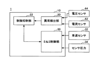
図3は、一実施例による制御系のシステム構成図である。 FIG. 3 is a system configuration diagram of a control system according to an embodiment.
制御系システム1は、処理装置10を含む。処理装置10は、CPUを含む演算処理装置により構成されてもよい。処理装置10の各種機能(以下で説明する機能を含む)は、任意のハードウェア、ソフトウェア、ファームウェア又はそれらの組み合わせにより実現されてもよい。例えば、処理装置10の機能の任意の一部又は全部は、特定用途向けASIC(application-specific integrated circuit)、FPGA(Field Programmable Gate Array)、DSP(digital signal processor)により実現されてもよい。また、処理装置10は、複数の処理装置(センサ内の処理装置を含む)により実現されてもよい。
The control system 1 includes a
処理装置10は、異常検出部20と、制御抑制部22と、S&S制御部30とを含む。尚、S&Sは、Stop & Startの略である。
The
S&S制御部30には、車速センサ32、及び、ブレーキブースタ70内の負圧(以下、「ブースタ負圧」という)を検出する圧力センサ34が接続される。S&S制御部30には、その他、後述の所定のアイドリングストップ開始条件等の判定に必要な各種情報(例えば、内気温やブレーキペダル操作量等に関する情報)が入力されてもよい。S&S制御部30は、制御抑制部22に接続される。制御抑制部22には、異常検出部20が接続され、異常検出部20には、電流センサ62が接続される。
The S & S
尚、異常検出部20、制御抑制部22及びS&S制御部30は、それぞれ、ECU(Electronic Control Unit)として具現化されてもよい。或いは、異常検出部20及び制御抑制部22は、1つのECUにより具現化され、S&S制御部30は、他の1つのECUにより具現化されてもよい。例えば、S&S制御部30は、エンジンを制御するエンジンECUとは別のアイドリングストップ制御ECUとして具現化されてもよい。尚、この場合、各ECUの接続態様は、任意である。例えば、接続態様は、CAN(controller area network)などのバスを介した接続であってもよいし、他のECU等を介した間接的な接続であってもよいし、直接的な接続であってもよいし、無線通信可能な接続態様であってもよい。
The
異常検出部20は、バッテリ60の異常状態を検出する。検出対象の異常状態は、例えば、スタータ52によるエンジン42の始動が不能になるような異常状態である。以下では、検出対象の異常状態は、一例として、バッテリ60のオープン故障状態であるとする。バッテリ60のオープン故障は、バッテリ60の内部がオープン故障したり、バッテリ60の端子(ハーネス端子)が外れたりすることにより生じる。バッテリ60の内部のオープン故障は、内部の機械的破損(極柱折れ、セル間溶接部破断等)、腐食性物質の侵入、電解液の蒸発、経時劣化等によって生じうる。尚、バッテリ60のオープン故障が発生すると、バッテリ60には電流が流れなくなるので、電流センサ62によって検出されるバッテリ電流は略0となる。
The
バッテリ60のオープン故障の検出方法は、多種多様であり、任意の方法が採用されてもよい。例えば、バッテリ60のオープン故障は、特開2007-225562公報に記載されるような方法で検出されてもよい。バッテリ60のオープン故障の検出方法の好ましい例については、後述する。
There are various methods for detecting an open failure of the
制御抑制部22は、異常検出部20の検出結果等に基づいて、S&S制御部30による制御を抑制する。これについては後述する。
The
S&S制御部30は、車速センサ32からの車速情報等に基づいて、所定のアイドリングストップ開始条件が成立したか否かを判定し、所定のアイドリングストップ開始条件が成立したと判定した場合に、エンジンを停止してアイドリングストップ制御を開始する。以下、便宜上、車両停止状態において実行されるアイドリングストップ制御を、「停止S&S」という。また、停止S&Sの開始条件を「停止S&S開始条件」という。停止S&S開始条件は、車速が0であることを含む。停止S&S開始条件に含まれるその他の条件は、任意であるが、例えば、電圧センサ64に基づきバッテリ60のオープン故障が検出されていないことや、ブレーキペダルが踏まれていることや、ブースタ負圧の大きさが所定値以上であること、その他、空調状態やバッテリ60の充電状態(SOC:State Of Charge)、道路勾配等に関する条件を含んでよい。
The S &
S&S制御部30は、車両減速状態においてもアイドリングストップ制御を開始する。以下、車両減速状態において実行されるアイドリングストップ制御を、「減速S&S」という。また、減速S&Sの開始条件を「減速S&S開始条件」という。減速S&S開始条件は、車速が所定車速Vth(以下、「E/G停止車速Vth」という)以下であることを含む。E/G停止車速Vthは、例えば13km/h程度の低車速領域内の値であってよいし、後述の如く可変されてもよい。減速S&S開始条件に含まれるその他の条件は、任意であるが、例えば、電圧センサ64に基づきバッテリ60のオープン故障が検出されていないことや、ブレーキペダルが踏まれていることや、ブースタ負圧の大きさが所定値以上であること、その他、空調状態やバッテリ60の充電状態、道路勾配等に関する条件を含んでよい。
The S &
図4は、S&S制御部30により実行されるS&S開始処理の一例を示すフローチャートであり、(A)は、減速S&Sに関する処理であり、(B)は、停止S&Sに関する処理である。図4(A)及び(B)に示す処理ルーチンは、それぞれ並列に、例えば、エンジン42の作動中、所定の処理周期毎に繰り返し実行される。
FIG. 4 is a flowchart illustrating an example of the S & S start process executed by the S &
図4(A)を参照するに、ステップ400では、減速S&S禁止フラグがセットされているか否かを判定する。減速S&S禁止フラグは、制御抑制部22によりセットされる場合がある。減速S&S禁止フラグについては後に詳説する。減速S&S禁止フラグがセットされている場合は、ステップ400に戻り、それ以外の場合は、ステップ402に進む。
Referring to FIG. 4A, in step 400, it is determined whether the deceleration S & S prohibition flag is set. The deceleration S & S prohibition flag may be set by the
ステップ402では、車速センサ32からの情報に基づいて、車速がE/G停止車速Vth以下であるか否かを判定する。車速がE/G停止車速Vth以下の場合は、ステップ404に進み、それ以外の場合は、ステップ400に戻る。
In
ステップ404では、他の減速S&S開始条件が成立したか否かを判定する。他の減速S&S開始条件は、上述の如く、電圧センサ64に基づきバッテリ60のオープン故障が検出されていないことや、ブレーキペダルが踏み込まれていること等の条件を含んでよい。他の減速S&S開始条件が成立した場合は、ステップ406に進み、それ以外の場合は、ステップ400に戻る。
In
ステップ406では、減速S&Sを開始する。即ち、エンジン42を停止する。
In step 406, deceleration S & S is started. That is, the
尚、図4(A)において、ステップ400、ステップ402及びステップ404の処理順序は任意である。例えば、ステップ402の判定処理はステップ400の判定処理よりも先に実行されてもよい。
In FIG. 4A, the processing order of step 400,
図4(B)を参照するに、ステップ410では、車速センサ32からの情報に基づいて、車速が0であるか否かを判定する。車速が0の場合は、ステップ412に進み、それ以外の場合は、ステップ410に戻る。
Referring to FIG. 4B, in step 410, it is determined based on the information from the
ステップ412では、他の停止S&S開始条件が成立したか否かを判定する。他の停止S&S開始条件は、上述の如く、電圧センサ64に基づきバッテリ60のオープン故障が検出されていないことや、ブレーキペダルが踏み込まれていること等の条件を含んでよい。他の停止S&S開始条件が成立した場合は、ステップ414に進み、それ以外の場合は、ステップ410に戻る。尚、他の停止S&S開始条件の判定は、繰り返し実行されなくてもよい。即ち、ステップ412で否定判定された場合は、そのまま終了してもよい(この場合、今回の車速0の事象に対しては停止S&Sは開始されない)。或いは、他の停止S&S開始条件の判定は、所定回数だけ又は所定期間だけ繰り返し実行されてもよい。
In step 412, it is determined whether another stop S & S start condition is satisfied. Other stop S & S start conditions may include conditions such as that an open failure of the
ステップ414では、停止S&Sを開始する。即ち、エンジン42を停止する。
In
尚、図4(B)において、ステップ410及びステップ412の処理順序は任意である。例えば、ステップ412の判定処理はステップ410の判定処理よりも先に実行されてもよい。 In FIG. 4B, the processing order of step 410 and step 412 is arbitrary. For example, the determination process in step 412 may be executed before the determination process in step 410.
図5は、S&S制御部30により実行されるS&S開始処理の他の一例を示すフローチャートである。図5に示す処理は、減速S&S禁止フラグを使用せずに、減速S&S及び停止S&Sを統合的に実行する構成(例えば、後述の図10、図12、図13参照)において好適である。ここでは、前提として、減速S&S開始条件と停止S&S開始条件とは、車速以外の条件については同一であるとし、単に「S&S開始条件」と称する。尚、減速S&S開始条件と停止S&S開始条件とは、車速以外の条件について異なってもよく、この場合は、車速に応じて異なる判定処理を実行すればよい。図5に示す処理ルーチンは、例えば、エンジン42の作動中、所定の処理周期毎に繰り返し実行される。
FIG. 5 is a flowchart showing another example of the S & S start process executed by the S &
ステップ500では、車速センサ32からの情報に基づいて、車速がE/G停止車速Vth以下であるか否かを判定する。車速がE/G停止車速Vth以下の場合は、ステップ502に進み、それ以外の場合は、ステップ500に戻る。
In step 500, based on the information from the
ステップ502では、他のS&S開始条件が成立したか否かを判定する。他のS&S開始条件は、上述の如く、電圧センサ64に基づきバッテリ60のオープン故障が検出されていないことや、ブレーキペダルが踏み込まれていること等の条件を含んでよい。他のS&S開始条件が成立した場合は、ステップ504に進み、それ以外の場合は、ステップ500に戻る。
In
ステップ504では、減速S&S又は停止S&Sを開始する。即ち、エンジン42を停止する。尚、このとき、車速が0のときは停止S&Sが開始されたことになり、車速が0より大きいときは減速S&Sが開始されたことになる。
In
図6は、S&S制御部30により実行されるS&S終了処理の他の一例を示すフローチャートである。図6に示す処理は、例えば、減速S&S又は停止S&Sの開始に伴うアイドリングストップ制御中、所定の処理周期毎に繰り返し実行される。
FIG. 6 is a flowchart illustrating another example of the S & S end process executed by the S &
ステップ600では、所定のアイドリングストップ終了条件が成立したか否かを判定する。所定のアイドリングストップ終了条件は、任意であるが、典型的には、例えば、ブレーキペダルの踏み込みが解除されたことや、ブースタ負圧の大きさが所定値未満になったこと、その他、空調状態(空調快適性の低下)やバッテリ状態(充電量の低下)等に関する条件を含んでよい。所定のアイドリングストップ終了条件が成立した場合は、ステップ602に進み、それ以外の場合は、ステップ600に戻る。 In step 600, it is determined whether a predetermined idling stop termination condition is satisfied. The predetermined idling stop termination condition is arbitrary, but typically, for example, the brake pedal is released, the booster negative pressure is less than the predetermined value, and other conditions such as air conditioning. Conditions regarding (decrease in air-conditioning comfort), battery state (decrease in charge amount), and the like may be included. If the predetermined idling stop termination condition is satisfied, the process proceeds to step 602. Otherwise, the process returns to step 600.
ステップ602では、エンジン42を再始動してアイドリングストップ制御を終了する。
In step 602, the
図7は、異常検出部20及び制御抑制部22により実行される処理の一例を示すフローチャートである。図7に示す処理ルーチンは、例えば、車両のイグニッションスイッチのオン時に起動され、その後、イグニッションスイッチがオフされるまで、所定の処理周期毎に繰り返し実行される。但し、ステップ700の処理(及びそれに伴いステップ702の処理)は、車両走行中のみ実行れる。図7に示す処理は、S&S制御部30が図4に示す処理を実行する場合に好適となる。
FIG. 7 is a flowchart illustrating an example of processing executed by the
ステップ700では、異常検出部20は、バッテリ60のオープン故障の有無を判定する。具体的には、電流センサ62の検出値に基づいて、バッテリ電流が所定範囲ΔA1内(本例では、−0.8[A]以上、且つ、0.8[A]以下)である状態が所定時間ΔT1継続したか否かを判定する。所定範囲ΔA1は、バッテリ60のオープン故障が生じた場合に電流センサ62の検出値が取り得る範囲に対応し、試験等により適合されてよい。典型的には、所定範囲ΔA1は、0[A]を中心とした範囲であり、電流センサ62のオフセットを考慮して設定される。即ち、電流センサ62には元来オフセットがありえ(又は経時的にオフセットが発生しうり)、実際には0[A]である場合でも、微小な電流値(例えば、0.8[A])を示す場合がある。所定時間ΔT1は、バッテリ60のオープン故障が生じていない場合でもバッテリ電流が所定範囲ΔA1内となることがある点を考慮して設定される。例えば、ノイズが発生した場合や、車両負荷50が作動していない場合は、バッテリ電流が所定範囲ΔA1内となることがありうる。所定時間ΔT1は、例えば5[s]であってよい。
In
ここで、所定範囲ΔA1は、好ましくは、比較的広く設定され、また、所定時間ΔT1は、好ましくは、比較的短く設定される。所定範囲ΔA1が広ければ広いほど、誤検出(正常にも拘らずオープン故障と判断)の可能性が高くなり、所定時間ΔT1が短ければ短いほど、誤検出の可能性が高くなる。従って、所定範囲ΔA1が比較的広く設定され、所定時間ΔT1が比較的短く設定されると、誤検出の可能性が高くなる。しかしながら、他方、所定範囲ΔA1が広ければ広いほど、実際にはバッテリ60のオープン故障が生じているのに検出できない事態(オープン故障検出失敗)の可能性が低くなり(即ちオープン故障の検出感度が高くなり)、所定時間ΔT1が短ければ短いほど、オープン故障検出失敗の可能性が低くなると共に、より早い検出が可能となる。この点、誤検出の場合は、後述の如く減速S&Sが禁止され、燃費向上機会が失われる反面、オープン故障検出失敗の場合は、減速S&S開始に伴うエンジン停止後にブースタ負圧が不足状態になってもエンジン42を始動できない事態が生じうる。このため、所定範囲ΔA1及び/又は所定時間ΔT1は、好ましくは、減速S&Sよりも、エンジン42を始動できない事態を回避することを優先する観点から、オープン故障の検出感度が高くなるように設定される。換言すると、所定範囲ΔA1及び/又は所定時間ΔT1は、好ましくは、減速S&Sによる燃費向上よりもブースタ負圧の確保による安全性を優先する観点から高感度に設定される。
Here, the predetermined range ΔA1 is preferably set relatively wide, and the predetermined time ΔT1 is preferably set relatively short. The wider the predetermined range ΔA1, the higher the possibility of erroneous detection (determined as an open failure despite normality), and the shorter the predetermined time ΔT1, the higher the possibility of erroneous detection. Therefore, if the predetermined range ΔA1 is set relatively wide and the predetermined time ΔT1 is set relatively short, the possibility of erroneous detection increases. However, on the other hand, the wider the predetermined range ΔA1, the lower the possibility of a situation in which an open failure of the
ステップ700において、バッテリ電流が所定範囲ΔA1内である状態が所定時間ΔT1継続したと判定した場合は、バッテリ60がオープン故障状態であると判断して、ステップ702に進む。他方、それ以外の場合は、バッテリ60のオープン故障でないと判断して、次の処理周期でステップ700の処理を再度行う。尚、ステップ700において、所定時間ΔT1継続したか否かは、ノイズの影響を考慮した態様で判定されてもよい。例えば、ある処理周期で、バッテリ電流が所定範囲ΔA1内である場合は、カウンタ値をインクリメントし、バッテリ電流が所定範囲ΔA1内でない場合は、カウンタ値をデクリメントすることとしてもよい。この場合、カウンタ値×処理周期を、バッテリ電流が所定範囲ΔA1内である継続時間として、カウンタ値×処理周期が所定時間ΔT1以上であるか否かを判定してもよい。
If it is determined in
ステップ702では、制御抑制部22は、減速S&S禁止フラグをセットする。即ち、減速S&S禁止フラグを立てる。減速S&S禁止フラグがセットされると、減速S&Sが禁止されることになる。但し、減速S&S禁止フラグがセットされた場合でも、停止S&Sは依然として開始可能な状態である。即ち、減速S&S禁止フラグがセットされた場合でも、停止S&S開始条件が満たされれば、停止S&Sは開始される。
In step 702, the
ステップ704では、制御抑制部22は、停止S&Sによりエンジン42が停止されたか否かを判定する。停止S&Sによりエンジン42が停止されたか否かは、S&S制御部30から得られる情報に基づいて判定されてよい。停止S&Sによりエンジン42が停止されたと判定した場合は、ステップ706に進み、それ以外の場合は、停止S&Sによるエンジン停止を待機する状態となる。
In step 704, the
ステップ706では、制御抑制部22は、停止S&Sの終了に伴いエンジン42が再始動されたか否かを判定する。エンジン42が再始動されたか否かは、S&S制御部30から得られる情報に基づいて判定されてよい。エンジン42が再始動されたと判定した場合は、ステップ708に進み、それ以外の場合は、エンジン再始動を待機する状態となる。
In
ステップ708では、制御抑制部22は、上記ステップ702でセットした減速S&S禁止フラグをクリアする。即ち、減速S&S禁止フラグを下ろす。これにより、その後、減速S&S開始条件が満たされた場合は、減速S&Sが開始されることになる。
In
ここで、上記ステップ700で肯定判定されたということは、バッテリ60のオープン故障が検出されたことを意味する。バッテリ60のオープン故障が発生すると、スタータ52が作動できないので、エンジン42の再始動が不能となる。これにも拘らず、上記ステップ706で肯定判定されたということは、上記ステップ700におけるバッテリ60のオープン故障の検出が誤りであった(即ち、誤検出であった)ことを意味する。このため、ステップ708では、減速S&S禁止フラグがクリアされる。
Here, the affirmative determination in
図7に示す処理によれば、上述の如く、バッテリ60のオープン故障が検出された場合には、減速S&Sが禁止される。これにより、バッテリ60のオープン故障時に減速S&Sを開始してしまう事態を低減することができる。バッテリ60のオープン故障時に減速S&Sを開始すると、減速S&S中に例えば運転者のブレーキペダルのポンピング操作によってブースタ負圧が不足しても、エンジン42を再始動できず、ブースタ負圧を確保することができなくなる。尚、かかる事態は、エンジン42の吸気負圧を利用してブースタ負圧を生成する方式のブレーキブースタ70に限られず、他の方式のブレーキブースタ70の場合も生じる。これは、バッテリ60のオープン故障時は、バッテリ60の電力で作動するアクチュエータ54が作動できないためである。図7に示す処理によれば、かかるブースタ負圧を確保できなくなる事態を低減し、安全性を高めることができる。
According to the process shown in FIG. 7, as described above, when an open failure of the
また、図7に示す処理によれば、上述の如く、バッテリ60のオープン故障が検出された場合でも、停止S&Sは許可される。これにより、バッテリ60のオープン故障の誤検出に起因して停止S&Sが実行されなくなるのを防止し、誤検出に対する商品性を確保することができる。即ち、バッテリ60のオープン故障の誤検出に起因した燃費向上機会の逸失を低減することができる。尚、バッテリ60のオープン故障が誤検出でなかった場合は、停止S&Sが開始されると、その後、ブースタ負圧が不足してもエンジン42を再始動できない状況に陥る。かかる状況は、好ましくない状況であるが、車速が0である状態であるので、停止状態を維持するために必要な制動力は小さく、必要な安全性は確保される。また、図7に示す処理では、上述の如く、バッテリ60のオープン故障の検出方法(所定範囲ΔA1及び/又は所定時間ΔT1)は、安全性を優先して誤検出が生じやすい傾向にあるので、かかる状況は稀にしか生じないことが予想される。このようにして、図7に示す処理によれば、ブースタ負圧を確保しつつ、燃費向上を図ることができる。
Further, according to the process shown in FIG. 7, the stop S & S is permitted even when an open failure of the
また、図7に示す処理によれば、上述の如く、バッテリ60のオープン故障は、バッテリ電流が所定範囲ΔA1内である状態が所定時間ΔT1継続した場合に検出される。このようなバッテリ60のオープン故障の検出方法は、特に、車両走行中にバッテリ60のオープン故障を検出するのに好適である。バッテリ60の電圧に基づいてバッテリ60のオープン故障を検出する方法もあるが、かかる方法は、車両走行中にバッテリ60のオープン故障を検出するのには不適である。これは、車両走行中は、オルタネータ40が動作しているので(即ち発電状態にあるので)、バッテリ60のオープン故障時においてもバッテリ60の電圧の有意な低下を検出できない場合があるためである。このようにして、図7に示す処理によれば、車両走行中にバッテリ60のオープン故障を検出することが可能となる。尚、車両走行中にバッテリ60のオープン故障を検出することは、上述の如く、バッテリ60のオープン故障の検出に伴って減速S&Sを禁止する構成であるが故に必要となる。これは、減速S&Sは車両走行状態で開始される制御であるためである。
Further, according to the process shown in FIG. 7, as described above, the open failure of the
また、図7に示す処理によれば、上述の如く、減速S&S禁止フラグがセットされた場合であっても、エンジン再始動が行われた場合(即ち、エンジン再始動が成功した場合)には、減速S&S禁止フラグがクリアされる。即ち、エンジン再始動が行われたことは、バッテリ60のオープン故障の誤検出を意味するので、減速S&S禁止フラグがクリアされる。従って、その後、再度、バッテリ60のオープン故障が検出されない限り、減速S&Sが開始可能な状態となる。このようにして、図7に示す処理によれば、バッテリ60のオープン故障の誤検出に起因して減速S&Sの禁止状態が継続されるのを防止することができる。
Further, according to the processing shown in FIG. 7, as described above, even when the deceleration S & S prohibition flag is set, when the engine is restarted (that is, when the engine restart is successful), The deceleration S & S prohibition flag is cleared. That is, the fact that the engine has been restarted means an erroneous detection of an open failure of the
尚、図7に示す処理では、上述の如く、ステップ706でエンジン再始動が行われた場合(即ち、エンジン再始動が成功した場合)に減速S&S禁止フラグがクリアされている。しかしながら、停止S&Sによりエンジン42が停止された後に、電流センサ62の検出信号に基づいて、所定値以上のバッテリ電流(例えば上記ステップ700で用いる所定範囲ΔA1を有意に超えるようなバッテリ電流)が検出された場合や、所定の車両負荷50が正常に動作した場合等に、減速S&S禁止フラグがクリアされてもよい。
In the process shown in FIG. 7, as described above, the deceleration S & S prohibition flag is cleared when the engine is restarted in step 706 (that is, when the engine restart is successful). However, after the
尚、図7に示す処理では、上述の如く、上記ステップ700では、バッテリ電流のみに基づいてバッテリ60のオープン故障を検出する簡易な方法を実現している。しかしながら、上述の如く、他の減速S&S開始条件には、電圧センサ64に基づきバッテリ60のオープン故障が検出されていないことが含まれている。従って、実質的には、車両走行中は、電圧センサ64及び電流センサ62のそれぞれに基づいて独立にバッテリ60のオープン故障の有無を判定していることになる。但し、他の減速S&S開始条件には、電圧センサ64に基づきバッテリ60のオープン故障が検出されていないことが含められなくてもよい。これは、上述の如く、車両走行中は、オルタネータ40が動作しているので、バッテリ60のオープン故障時においてもバッテリ60の電圧の有意な低下を検出できない場合があるためである。尚、車両停止中は、電流センサ62によるオープン故障の有無は判定されず、電圧センサ64に基づいてバッテリ60のオープン故障の有無が判定される。
In the process shown in FIG. 7, as described above, in
また、図7に示す処理では、上述の如く、バッテリ60がオープン故障を検出した場合に減速S&S禁止フラグをセットすることで減速S&Sを禁止しているが、バッテリ60がオープン故障を検出した場合に、減速S&S開始条件に含まれるその他の条件を変更して、実質的に同様の構成を実現することも可能である。例えば、バッテリ60がオープン故障を検出した場合に、ブースタ負圧の大きさに対する閾値を無限大等に増加することで、減速S&Sを禁止することとしてもよい。
In the processing shown in FIG. 7, as described above, when the
図8は、異常検出部20及び制御抑制部22により実行される処理の他の一例を示すフローチャートである。図8に示す処理ルーチンは、例えば、車両のイグニッションスイッチのオン時に起動され、その後、イグニッションスイッチがオフされるまで、所定の処理周期毎に繰り返し実行される。但し、ステップ800乃至ステップ803の処理は、車両走行中のみ実行される。図8に示す処理は、S&S制御部30が図4に示す処理を実行する場合に好適となる。
FIG. 8 is a flowchart illustrating another example of processing executed by the
図8に示す処理は、図7に示した処理に対して、ステップ803が追加された点が主に異なる。図8に示すステップ800、ステップ802、ステップ806及びステップ808の各処理は、図7に示したステップ700、ステップ702、ステップ706及びステップ708の各処理と同様であってよい。以下では、図8に特有の処理について説明する。
The process shown in FIG. 8 is mainly different from the process shown in FIG. 7 in that step 803 is added. Each process of
ステップ802に続いて実行されるステップ803では、異常検出部20は、バッテリ60のオープン故障の有無を再度判定する。具体的には、電流センサ62の検出値に基づいて、バッテリ電流が所定範囲ΔA2内(本例では、−0.8[A]未満、又は、0.8[A]より大きい)である状態が所定時間ΔT2継続したか否かを判定する。所定範囲ΔA2は、バッテリ60のオープン故障が生じた場合に電流センサ62の検出値が取り得る範囲を含まないように設定され、試験等により適合されてよい。所定範囲ΔA2は、ステップ800で用いられる所定範囲Δ1を含まない範囲である。本例では、所定範囲ΔA2は、「−0.8[A]未満、又は、0.8[A]より大きい」であり、所定範囲ΔA1(本例では、−0.8[A]以上、且つ、0.8[A]以下)に対しては、マージンを設けない範囲である。しかしながら、例えば、所定範囲ΔA2は、「−1.0[A]未満、又は、1.0[A]より大きい」といった具合に、所定範囲ΔA1に対してマージンを設けてもよい。尚、このマージンは、ステップ800の判定条件と同様、減速S&Sよりも、エンジン42を始動できない事態を回避することを優先する観点から、比較的大きく設定されてもよい。所定時間ΔT2は、ステップ800で用いる所定時間ΔT1と同様の観点から設定されてよく、例えば5[s]であってよい。
In step 803 executed following step 802, the
尚、ステップ803において、所定時間ΔT2継続したか否かは、ノイズの影響を考慮した態様で判定されてもよい。例えば、ある処理周期で、バッテリ電流が所定範囲ΔA2内である場合は、カウンタ値をインクリメントし、バッテリ電流が所定範囲ΔA2内でない場合は、カウンタ値をデクリメントすることとしてもよい。この場合、カウンタ値×処理周期を、バッテリ電流が所定範囲ΔA2内である継続時間として、カウンタ値×処理周期が所定時間ΔT2以上であるか否かを判定してもよい。 In step 803, whether or not the predetermined time ΔT2 has continued may be determined in a manner that considers the influence of noise. For example, when the battery current is within the predetermined range ΔA2 in a certain processing cycle, the counter value may be incremented, and when the battery current is not within the predetermined range ΔA2, the counter value may be decremented. In this case, it is possible to determine whether the counter value × processing cycle is equal to or longer than the predetermined time ΔT2 with the counter value × processing cycle being a duration during which the battery current is within the predetermined range ΔA2.
ステップ803において、バッテリ電流が所定範囲ΔA2である状態が所定時間ΔT2継続したと判定した場合には、ステップ808に進み、それ以外の場合は、ステップ804に進む。従って、図8に示す処理では、ステップ806で肯定判定されない場合でも、バッテリ電流が所定範囲ΔA2である状態が所定時間ΔT2継続したと判定した場合には、減速S&S禁止フラグがクリアされる。 If it is determined in step 803 that the battery current is in the predetermined range ΔA2 for a predetermined time ΔT2, the process proceeds to step 808. Otherwise, the process proceeds to step 804. Therefore, in the process shown in FIG. 8, the deceleration S & S prohibition flag is cleared when it is determined that the state in which the battery current is in the predetermined range ΔA2 has continued for the predetermined time ΔT2 even if the determination in step 806 is not affirmative.
ステップ804では、制御抑制部22は、停止S&Sによりエンジン42が停止されたか否かを判定する。停止S&Sによりエンジン42が停止されたか否かは、S&S制御部30から得られる情報に基づいて判定されてよい。停止S&Sによりエンジン42が停止されたと判定した場合は、ステップ806に進み、それ以外の場合は、ステップ803に戻る。
In step 804, the
図8に示す処理によれば、図7に示した処理と同様の効果が得られる。また、図8に示す処理によれば、一旦、ステップ800で肯定判定されて減速S&S禁止フラグがセットされても、その後、停止S&Sが開始されるまでは、ステップ803の判定処理の判定結果に応じて減速S&S禁止フラグがクリアされる可能性がある。即ち、一旦、ステップ800でバッテリ60のオープン故障が検出されて減速S&S禁止フラグがセットされた場合でも、その後、バッテリ60のオープン故障の有無が再度確認される。これにより、ステップ800でバッテリ60のオープン故障を誤検出した場合でも、その後の見直しにより減速S&Sフラグをクリアすることが可能となる。この結果、バッテリ60のオープン故障の誤検出に起因した燃費向上機会の逸失を低減することができる。
According to the process shown in FIG. 8, the same effect as the process shown in FIG. 7 can be obtained. Further, according to the process shown in FIG. 8, even if an affirmative determination is made in
尚、図8に示す処理では、一旦、ステップ800でバッテリ60のオープン故障が検出されて減速S&S禁止フラグがセットされた場合、停止S&Sによりエンジン42が停止されるまで、ステップ803の判定処理は、所定の処理周期毎に繰り返し実行される。しかしながら、ステップ803の判定処理は、停止S&Sによりエンジン42が停止されるまで、1回だけ実行されてもよいし、2回以上の所定回数だけ実行されてもよい。また、ステップ803の判定処理は、停止S&Sによりエンジン42が停止されるまで、所定時間(≫所定の処理周期)経過毎に実行されてもよいし、所定走行距離毎に実行されてもよい。
In the process shown in FIG. 8, when an open failure of the
図9は、異常検出部20及び制御抑制部22により実行される処理の他の一例を示すフローチャートである。図9に示す処理ルーチンは、例えば、車両のイグニッションスイッチのオン時に起動され、その後、イグニッションスイッチがオフされるまで、所定の処理周期毎に繰り返し実行される。図9に示す処理は、S&S制御部30が図4に示す処理を実行する場合に好適となる。
FIG. 9 is a flowchart illustrating another example of processing executed by the
図9に示す処理は、前提として、電圧センサ64及び電流センサ62は、これらと処理装置(例えばマイコン)を一体的に組み込んだセンサ(以下、便宜上、「インテリジェントバッテリセンサ」という)により形成されているものとする。かかるインテリジェントバッテリセンサは、温度センサも内部に組み込まれている。以下では、前提として、インテリジェントバッテリセンサは、内部の処理装置がバッテリ端子外れ等のバッテリ60のオープン故障を検出する機能を有し、かかるバッテリ60のオープン故障を検出した場合に、バッテリ破損情報をS&S制御部30に出力するものとする。
The processing shown in FIG. 9 is premised on that the
図9に示す処理は、図7に示した処理に対して、ステップ900の処理が主に異なる。図9に示すステップ902乃至ステップ908の各処理は、図7に示したステップ702乃至ステップ708の各処理と同様であってよい。以下では、図9に特有の処理について説明する。 The processing shown in FIG. 9 is mainly different from the processing shown in FIG. Each process of step 902 to step 908 shown in FIG. 9 may be the same as each process of step 702 to step 708 shown in FIG. Hereinafter, processing unique to FIG. 9 will be described.
ステップ900では、異常検出部20は、インテリジェントバッテリセンサからバッテリ破損情報を受信したか否かを判定する。インテリジェントバッテリセンサからバッテリ破損情報を受信した場合は、バッテリ60がオープン故障状態であると判断して、ステップ902に進む。他方、それ以外の場合は、バッテリ60がオープン故障状態でないと判断して、次の処理周期でステップ900の処理を再度行う。
In
図9に示す処理によれば、図7に示した処理と同様の効果が得られる。尚、図9に示す処理は、特に、インテリジェントバッテリセンサによるオープン故障の検出精度が低い場合に特に好適である。これは、上述の如く、減速S&Sよりも、エンジン42を始動できない事態を回避することを優先する観点からである。
According to the process shown in FIG. 9, the same effect as the process shown in FIG. 7 can be obtained. The process shown in FIG. 9 is particularly suitable when the open battery failure detection accuracy by the intelligent battery sensor is low. This is from the viewpoint of giving priority to avoiding the situation where the
尚、図9に示す処理において、ステップ900及びステップ902の処理は、車両走行中のみ実行されてよい。これは、インテリジェントバッテリセンサによるオープン故障の検出精度は、車両停止時には電圧値の低下を考慮することで高くなりうるためである。
In the process shown in FIG. 9, the processes in
図10は、異常検出部20及び制御抑制部22により実行される処理の他の一例を示すフローチャートである。図10に示す処理ルーチンは、例えば、車両のイグニッションスイッチのオン時に起動され、その後、イグニッションスイッチがオフされるまで、所定の処理周期毎に繰り返し実行される。但し、ステップ1000の処理(及びそれに伴いステップ1002の処理)は、車両走行中のみ実行される。
FIG. 10 is a flowchart illustrating another example of processing executed by the
図10に示す処理は、前提として、減速S&Sは、E/G停止車速Vth以下の減速状態で実行されるものとする。換言すると、減速S&S開始条件には、E/G停止車速Vth以下の減速状態であることが含まれる。また、図10に示す例においては、減速S&S禁止フラグは使用されないので、減速S&S禁止フラグは省略されてよい。従って、図10に示す処理は、S&S制御部30が図5に示す処理を実行する場合に好適となる。
In the process shown in FIG. 10, it is assumed that the deceleration S & S is executed in a deceleration state that is equal to or lower than the E / G stop vehicle speed Vth. In other words, the deceleration S & S start condition includes a deceleration state equal to or lower than the E / G stop vehicle speed Vth. Further, in the example shown in FIG. 10, the deceleration S & S prohibition flag is not used, so the deceleration S & S prohibition flag may be omitted. Therefore, the process shown in FIG. 10 is suitable when the S &
図10に示す処理は、図7に示した処理に対して、バッテリ60のオープン故障が検出された場合に減速S&Sを禁止するのではなく、バッテリ60のオープン故障が検出された場合に減速S&Sの開始可能な車速を低減する点が主に異なる。図10に示すステップ1000及びステップ1004の各処理は、図7に示したステップ700及びステップ704の各処理と同様であってよい。以下では、図8に特有の処理について説明する。
The processing shown in FIG. 10 does not prohibit the deceleration S & S when the open failure of the
ステップ1002では、制御抑制部22は、E/G停止車速Vthを所定値V1に設定する。E/G停止車速Vthの初期値は、通常値V0であってよい。通常値V0は、無限大を含む任意であるが、例えば13km/h程度の低車速領域内の値であってよい。所定値V1は、0よりも大きい任意の値であってよいが、通常値V0よりも小さい値である。尚、所定値V1が0のときは、実質的に減速S&Sが禁止されること(停止S&Sのみが許容されること)を意味するので、図10に示す処理は、図7に示した処理と等価になる。
In step 1002, the
ステップ1004では、制御抑制部22は、減速S&S又は停止S&Sによりエンジン42が停止されたか否かを判定する。減速S&S又は停止S&Sによりエンジン42が停止されたか否かは、S&S制御部30から得られる情報に基づいて判定されてよい。減速S&S又は停止S&Sによりエンジン42が停止されたと判定した場合は、ステップ1006に進み、それ以外の場合は、減速S&S又は停止S&Sによるエンジン停止を待機する状態となる。
In step 1004, the
ステップ1006では、制御抑制部22は、減速S&S又は停止S&Sの終了に伴いエンジン42が再始動されたか否かを判定する。エンジン42が再始動されたか否かは、S&S制御部30から得られる情報に基づいて判定されてよい。エンジン42が再始動されたと判定した場合は、ステップ1008に進み、それ以外の場合は、エンジン再始動を待機する状態となる。
In
ステップ1008では、制御抑制部22は、E/G停止車速Vthを通常値V0に設定する。即ち、上記ステップ1002で所定値V1に設定されたE/G停止車速Vthが通常値V0に戻される。
In
図10に示す処理によれば、上述の如く、バッテリ60のオープン故障が検出された場合には、減速S&S開始条件のE/G停止車速Vthが通常値V0から所定値V1に低減される。これにより、バッテリ60のオープン故障時に、所定値V1よりも高い車速領域で減速S&Sを開始してしまう事態を低減することができる。バッテリ60のオープン故障時に減速S&Sを開始すると、減速S&S中に例えば運転者のブレーキペダルのポンピング操作によってブースタ負圧が不足しても、エンジン42を再始動できず、ブースタ負圧を確保することができなくなる。かかる事態は、特に、停止までに比較的大きい制動力が必要となる比較的高い車速領域において望ましくない。図10に示す処理によれば、比較的高い車速領域においてブースタ負圧を確保できなくなる事態を低減し、安全性を高めることができる。
According to the process shown in FIG. 10, as described above, when an open failure of the
また、図10に示す処理によれば、上述の如く、バッテリ60のオープン故障が検出された場合でも、所定値V1以下の車速領域では減速S&Sは許可される(停止S&Sも許可される)。これにより、バッテリ60のオープン故障の誤検出に起因して減速S&Sや停止S&Sが実行されなくなるのを防止し、誤検出に対する商品性を確保することができる。即ち、バッテリ60のオープン故障の誤検出に起因した燃費向上機会の逸失を低減することができる。尚、バッテリ60のオープン故障が誤検出でなかった場合は、停止S&S又は停止S&Sが開始されると、その後、ブースタ負圧が不足してもエンジン42を再始動できない状況に陥る。かかる状況は、好ましくない状況であるが、車速が0又は所定値V1以下の低車速領域である状態であるので、停止状態に至るために必要な制動力又は停止状態を維持するために必要な制動力は小さく、必要な安全性は確保される。また、図10に示す処理では、上述の如く、バッテリ60のオープン故障の検出方法(所定範囲ΔA1及び/又は所定時間ΔT1)は、安全性を優先して誤検出が生じやすい傾向にあるので、かかる状況は稀にしか生じないことが予想される。このようにして、図10に示す処理によれば、ブースタ負圧を確保しつつ、燃費向上を図ることができる。
Further, according to the process shown in FIG. 10, as described above, even when an open failure of the
また、図10に示す処理によれば、上述の如く、バッテリ60のオープン故障は、バッテリ電流が所定範囲ΔA1内である状態が所定時間ΔT1継続した場合に検出される。このようなバッテリ60のオープン故障の検出方法は、特に、車両走行中にバッテリ60のオープン故障を検出するのに好適である。尚、車両走行中にバッテリ60のオープン故障を確実に検出することは、上述の如く、バッテリ60のオープン故障を検出した場合に減速S&S開始条件のE/G停止車速Vthを通常値V0から所定値V1に低減する構成であるが故に必要となる。これは、減速S&Sは車両走行状態で開始される制御であるためである。
Further, according to the process shown in FIG. 10, as described above, the open failure of the
また、図10に示す処理によれば、上述の如く、E/G停止車速Vthが通常値V0から所定値V1に低減された場合であっても、エンジン再始動が行われた場合(即ち、エンジン再始動が成功した場合)には、E/G停止車速Vthが通常値V0に戻される。即ち、エンジン再始動が行われたことは、バッテリ60のオープン故障の誤検出を意味するので、E/G停止車速Vthが通常値V0に戻される。従って、その後、再度、バッテリ60のオープン故障が検出されない限り、所定値V1よりも高い車速領域において減速S&Sが開始可能な状態となる。このようにして、図10に示す処理によれば、バッテリ60のオープン故障の誤検出に起因して、所定値V1よりも高い車速領域において減速S&Sの禁止状態が継続されるのを防止することができる。
Further, according to the process shown in FIG. 10, as described above, even when the E / G stop vehicle speed Vth is reduced from the normal value V0 to the predetermined value V1, the engine is restarted (that is, When engine restart is successful), the E / G stop vehicle speed Vth is returned to the normal value V0. That is, the fact that the engine has been restarted means an erroneous detection of an open failure of the
尚、図10に示す処理では、上述の如く、ステップ1006でエンジン再始動が行われた場合(即ち、エンジン再始動が成功した場合)にE/G停止車速Vthが通常値V0に戻されている。しかしながら、減速S&S又は停止S&Sによりエンジン42が停止された後に、電流センサ62の検出信号に基づいて、所定値以上のバッテリ電流(例えば上記ステップ1000で用いる所定範囲ΔA1を有意に超えるようなバッテリ電流)が検出された場合や、所定の車両負荷50が正常に動作した場合等に、E/G停止車速Vthが通常値V0に戻されてもよい。
In the process shown in FIG. 10, as described above, when the engine is restarted in step 1006 (that is, when the engine restart is successful), the E / G stop vehicle speed Vth is returned to the normal value V0. Yes. However, after the
図11は、所定値V1の設定方法の一例の説明図である。図11には、横軸に車速が示され、縦軸にE/G再始動失敗確率[ppm]が示されている。尚、ppmは、100万分の1を表す。E/G再始動失敗確率とは、減速S&S又は停止S&Sによるエンジン停止後にエンジン42を再始動できない状況になる確率である。図11において、曲線C1で仕切られた領域の上側の領域"NG"は、エンジン42を再始動できないことが許容されない領域であり、曲線C1で仕切られた領域の下側の領域"OK"は、エンジン42を再始動できないことが許容される領域である。曲線C1は、設計思想に基づて設定されるが、典型的には、車速が低いほど、許容されるE/G再始動失敗確率が高くなる関係であってよい。
FIG. 11 is an explanatory diagram of an example of a method for setting the predetermined value V1. In FIG. 11, the abscissa indicates the vehicle speed, and the ordinate indicates the E / G restart failure probability [ppm]. In addition, ppm represents 1 millionth. The E / G restart failure probability is a probability that the
図11において、E/G再始動失敗確率P1は、図10のステップ1000におけるバッテリ60のオープン故障の判定方法を用いた場合のE/G再始動失敗確率に対応する。換言すると、E/G再始動失敗確率P1は、図10のステップ1000によりバッテリ60のオープン故障の検出精度(信頼度)に対応する。このとき、E/G停止車速Vthが通常値V0であると、E/G再始動失敗確率P1は、図11に示すように、領域"NG"に属する。従って、所定値V1は、図11に示すように、E/G再始動失敗確率P1が領域"OK"内に属するように設定される。
In FIG. 11, the E / G restart failure probability P1 corresponds to the E / G restart failure probability when the method for determining an open failure of the
図12は、異常検出部20及び制御抑制部22により実行される処理の他の一例を示すフローチャートである。図12に示す処理ルーチンは、例えば、車両のイグニッションスイッチのオン時に起動され、その後、イグニッションスイッチがオフされるまで、所定の処理周期毎に繰り返し実行される。但し、ステップ1200、ステップ1202及びステップ1203の処理は、車両走行中のみ実行される。
FIG. 12 is a flowchart illustrating another example of processing executed by the
図12に示す処理は、図10に示した処理に対して、ステップ1203が追加された点が主に異なる。図12に示すステップ1200、ステップ1202、ステップ1206及びステップ1208の各処理は、図10に示したステップ1000、ステップ1002、ステップ1006及びステップ1008の各処理と同様であってよい。以下では、図12に特有の処理について説明する。
The process shown in FIG. 12 is mainly different from the process shown in FIG. 10 in that step 1203 is added. Each process of step 1200,
図12に示す処理は、図10に示した処理と同様、前提として、減速S&Sは、E/G停止車速Vth以下の減速状態で実行されるものとする。換言すると、減速S&S開始条件には、E/G停止車速Vth以下の減速状態であることが含まれる。尚、図12に示す例においては、減速S&S禁止フラグは使用されないので、減速S&S禁止フラグは省略されてよい。従って、図12に示す処理は、S&S制御部30が図5に示す処理を実行する場合に好適となる。
In the process shown in FIG. 12, as in the process shown in FIG. 10, it is assumed that the deceleration S & S is executed in a deceleration state equal to or lower than the E / G stop vehicle speed Vth. In other words, the deceleration S & S start condition includes a deceleration state equal to or lower than the E / G stop vehicle speed Vth. In the example shown in FIG. 12, the deceleration S & S prohibition flag is not used, so the deceleration S & S prohibition flag may be omitted. Therefore, the process shown in FIG. 12 is suitable when the S &
ステップ1203では、異常検出部20は、図8に示したステップ803と同様の態様で、バッテリ60のオープン故障の有無を再度判定する。ステップ1203において、バッテリ電流が所定範囲ΔA2である状態が所定時間ΔT2継続したと判定した場合には、ステップ1208に進み、それ以外の場合は、ステップ1204に進む。従って、図12に示す処理では、ステップ1206で肯定判定されない場合でも、バッテリ電流が所定範囲ΔA2である状態が所定時間ΔT2継続したと判定した場合には、E/G停止車速Vthが通常値V0に戻される。
In step 1203, the
ステップ1204では、制御抑制部22は、減速S&S又は停止S&Sによりエンジン42が停止されたか否かを判定する。減速S&S又は停止S&Sによりエンジン42が停止されたか否かは、S&S制御部30から得られる情報に基づいて判定されてよい。減速S&S又は停止S&Sによりエンジン42が停止されたと判定した場合は、ステップ1206に進み、それ以外の場合は、ステップ1203に戻る。
In
図12に示す処理によれば、図10に示した処理と同様の効果が得られる。また、図12に示す処理によれば、一旦、ステップ1200で肯定判定されてE/G停止車速Vthが所定値V1に設定されても、その後、減速S&S又は停止S&Sが開始されるまでは、ステップ1203の判定処理の判定結果に応じてE/G停止車速Vthが通常値V0に戻される可能性がある。即ち、一旦、ステップ1200でバッテリ60のオープン故障が検出されてE/G停止車速Vthが所定値V1に設定された場合でも、その後、バッテリ60のオープン故障の有無が再度確認される。これにより、ステップ1200でバッテリ60のオープン故障を誤検出した場合でも、その後の見直しによりE/G停止車速Vthを通常値V0に戻すことが可能となる。この結果、バッテリ60のオープン故障の誤検出に起因した燃費向上機会の逸失を低減することができる。
According to the process shown in FIG. 12, the same effect as the process shown in FIG. 10 can be obtained. Further, according to the process shown in FIG. 12, even if the affirmative determination is made in step 1200 and the E / G stop vehicle speed Vth is set to the predetermined value V1, the deceleration S & S or the stop S & S is thereafter started. There is a possibility that the E / G stop vehicle speed Vth is returned to the normal value V0 according to the determination result of the determination processing in step 1203. That is, even if an open failure of the
尚、図12に示す処理では、一旦、ステップ1200でバッテリ60のオープン故障が検出されてE/G停止車速Vthが所定値V1に設定された場合、減速S&S又は停止S&Sによりエンジン42が停止されるまで、ステップ1203の判定処理は、所定の処理周期毎に繰り返し実行される。しかしながら、ステップ1203の判定処理は、減速S&S又は停止S&Sによりエンジン42が停止されるまで、1回だけ実行されてもよいし、2回以上の所定回数だけ実行されてもよい。また、ステップ1203の判定処理は、減速S&S又は停止S&Sによりエンジン42が停止されるまで、所定時間(≫所定の処理周期)経過毎に実行されてもよいし、所定走行距離毎に実行されてもよい。
In the process shown in FIG. 12, once an open failure of the
図13は、異常検出部20及び制御抑制部22により実行される処理の他の一例を示すフローチャートである。図13に示す処理ルーチンは、例えば、車両のイグニッションスイッチのオン時に起動され、その後、イグニッションスイッチがオフされるまで、所定の処理周期毎に繰り返し実行される。但し、ステップ1300及びステップ1302の処理は、車両走行中のみ実行される。
FIG. 13 is a flowchart illustrating another example of processing executed by the
図13に示す処理は、図10に示した処理と同様、前提として、減速S&Sは、E/G停止車速Vth以下の減速状態で実行されるものとする。換言すると、減速S&S開始条件には、E/G停止車速Vth以下の減速状態であることが含まれる。尚、図13に示す例においては、減速S&S禁止フラグは使用されないので、減速S&S禁止フラグは省略されてよい。従って、図13に示す処理は、S&S制御部30が図5に示す処理を実行する場合に好適となる。
In the process shown in FIG. 13, as in the process shown in FIG. 10, it is assumed that the deceleration S & S is executed in a deceleration state equal to or lower than the E / G stop vehicle speed Vth. In other words, the deceleration S & S start condition includes a deceleration state equal to or lower than the E / G stop vehicle speed Vth. In the example shown in FIG. 13, the deceleration S & S prohibition flag is not used, so the deceleration S & S prohibition flag may be omitted. Therefore, the process shown in FIG. 13 is suitable when the S &
ステップ1300では、異常検出部20は、電流センサ62の検出値に基づいて、バッテリ電流が所定範囲ΔA1内である状態の継続時間ΔTNを算出する。継続時間ΔTNの初期値は0である。継続時間ΔTNは、カウンタにより算出されてもよい。例えば、ある処理周期で、バッテリ電流が所定範囲ΔA1内である場合は、カウンタ値をインクリメントし、バッテリ電流が所定範囲ΔA1内でない場合は、カウンタ値をデクリメントすることとしてもよい。この場合、カウンタ値×処理周期が継続時間ΔTNに対応する。継続時間ΔTNは、バッテリ60のオープン故障の可能性を表す指標値であり、長くなるほどバッテリ60のオープン故障の可能性が高いことを意味する。
In step 1300, the
ステップ1302では、制御抑制部22は、E/G停止車速Vthを、上記ステップ1300で算出された継続時間ΔTNに応じた値V(ΔTN)に設定する。値V(ΔTN)は、継続時間ΔTNが長くなるほど小さくなる態様で設定される。例えば、値V(ΔTN)は、図11に示した考え方に基づいて、可変されてもよい。具体的には、E/G再始動失敗確率P1を継続時間ΔTNから換算(例えば、E/G再始動失敗確率P1は継続時間ΔTNと比例関係)して導出し、E/G再始動失敗確率P1が領域"OK"内に属するように、継続時間ΔTNに応じた値V(ΔTN)が設定される。
In step 1302, the
或いは、簡易的に、継続時間ΔTNが0のときの値V(ΔTN)は、通常値V0(図10参照)であってよい。また、継続時間ΔTNが所定時間ΔT1となったときの値V(ΔTN)は、所定値V1であってよい。この場合、値V(ΔTN)は、継続時間ΔTNの増加に伴って通常値V0から所定値V1へと線形的又は非線形的に低減されてよい。このとき、継続時間ΔTNが所定時間ΔT1を超えた場合は、値V(ΔTN)は、所定値V1を維持してもよいし、継続時間ΔTNの増加に伴って0に向けて低減されてもよい。 Or, simply, the value V (ΔTN) when the duration ΔTN is 0 may be the normal value V0 (see FIG. 10). Further, the value V (ΔTN) when the duration time ΔTN becomes the predetermined time ΔT1 may be the predetermined value V1. In this case, the value V (ΔTN) may be reduced linearly or nonlinearly from the normal value V0 to the predetermined value V1 as the duration time ΔTN increases. At this time, if the duration ΔTN exceeds the predetermined time ΔT1, the value V (ΔTN) may be maintained at the predetermined value V1, or may be reduced toward 0 as the duration ΔTN increases. Good.
ステップ1304では、制御抑制部22は、減速S&S又は停止S&Sによりエンジン42が停止されたか否かを判定する。減速S&S又は停止S&Sによりエンジン42が停止されたか否かは、S&S制御部30から得られる情報に基づいて判定されてよい。減速S&S又は停止S&Sによりエンジン42が停止されたと判定した場合は、ステップ1306に進み、それ以外の場合は、ステップ1300に戻る。
In step 1304, the
ステップ1306では、制御抑制部22は、減速S&S又は停止S&Sの終了に伴いエンジン42が再始動されたか否かを判定する。エンジン42が再始動されたか否かは、S&S制御部30から得られる情報に基づいて判定されてよい。エンジン42が再始動されたと判定した場合は、ステップ1308に進み、それ以外の場合は、エンジン再始動を待機する状態となる。
In
ステップ1308では、異常検出部20は、継続時間ΔTNを初期値0にリセットする。
In step 1308, the
図13に示す処理によれば、減速S&S開始条件のE/G停止車速Vthが継続時間ΔTNに応じた値V(ΔTN)に設定される。継続時間ΔTNは、上述の如く、バッテリ電流が所定範囲ΔA1内である状態の継続時間であり、バッテリ60のオープン故障の可能性を表す指標値である。また、値V(ΔTN)は、上述の如く、継続時間ΔTNが長くなるほど小さくなる態様で設定される。従って、値V(ΔTN)は、バッテリ60のオープン故障の可能性が高いほど小さくなる態様で設定される。これにより、バッテリ60のオープン故障の可能性が高いほど減速S&S開始条件のE/G停止車速Vthを低減することができる。
According to the processing shown in FIG. 13, the deceleration S & S start condition E / G stop vehicle speed Vth is set to a value V (ΔTN) corresponding to the duration ΔTN. The duration ΔTN is a duration in a state where the battery current is within the predetermined range ΔA1 as described above, and is an index value representing the possibility of an open failure of the
尚、図13に示す処理において、継続時間ΔTNは、エンジン42の再始動以外の所定の条件を満たした場合にもリセットされてよい。例えば、図10に示した考え方に基づいて、継続時間ΔTNは、バッテリ電流が所定範囲ΔA2である状態が所定時間ΔT2継続した場合にリセットされてもよい。
In the process shown in FIG. 13, the duration ΔTN may be reset even when a predetermined condition other than the restart of the
以上、各実施例について詳述したが、特定の実施例に限定されるものではなく、特許請求の範囲に記載された範囲内において、種々の変形及び変更が可能である。また、前述した実施例の構成要素を全部又は複数を組み合わせることも可能である。 Although each embodiment has been described in detail above, it is not limited to a specific embodiment, and various modifications and changes can be made within the scope described in the claims. It is also possible to combine all or a plurality of the components of the above-described embodiments.
例えば、上述した実施例では、減速S&Sは、減速状態であることを条件として実行されているが、減速状態以外の状態で実行されてもよい。即ち、減速S&Sは、車両非停止状態で実行されるS&S(非停止S&S)に置換されてもよい。車両非停止状態は、減速状態及び/又は定常走行状態(又はニュートラル走行状態)であってもよい。また、車両非停止状態は、車速がE/G停止車速Vth以下の走行状態であってもよい。E/G停止車速Vth以下の走行状態は、E/G停止車速Vth以下の減速状態、及び/又は、所E/G停止車速Vth以下の定常走行状態(又はニュートラル走行状態)であってもよい。また、減速状態は、所定減速度以下の減速状態であってもよいし、単にブレーキペダルが操作されている状態であってもよい。 For example, in the above-described embodiment, the deceleration S & S is executed on the condition that it is in the deceleration state, but may be executed in a state other than the deceleration state. That is, the deceleration S & S may be replaced with S & S (non-stop S & S) executed in the vehicle non-stop state. The vehicle non-stop state may be a deceleration state and / or a steady travel state (or a neutral travel state). Further, the vehicle non-stop state may be a traveling state in which the vehicle speed is equal to or lower than the E / G stop vehicle speed Vth. The travel state below the E / G stop vehicle speed Vth may be a deceleration state below the E / G stop vehicle speed Vth and / or a steady travel state (or neutral travel state) below the E / G stop vehicle speed Vth. . Further, the deceleration state may be a deceleration state with a predetermined deceleration or less, or may be a state where the brake pedal is simply operated.
1 制御系システム
10 処理装置
20 異常検出部
22 制御抑制部
30 S&S制御部
60 バッテリ
70 ブレーキブースタ
DESCRIPTION OF SYMBOLS 1
Claims (8)
車速が0よりも高い車両非停止状態において前記電流センサの出力信号に基づいて前記バッテリの異常状態を検出する処理装置とを含み、
前記処理装置は、車速が所定車速以下であることを含む所定の開始条件を満たした場合に前記車両非停止状態におけるアイドリングストップ制御を開始し、
前記処理装置は、前記バッテリの異常状態を検出しない場合は、前記所定車速を第1の値に設定し、前記バッテリの異常状態を検出した場合は、前記所定車速を前記第1の値よりも低い第2の値に設定する、車両制御装置。 A current sensor for detecting the current value of the battery;
Look including a processing unit that detect the abnormal state of the battery based on an output signal of the current sensor in a high vehicle non stop state than the vehicle speed is 0,
The processing device starts idling stop control in the vehicle non-stop state when a predetermined start condition including that the vehicle speed is equal to or lower than a predetermined vehicle speed is satisfied,
The processing device sets the predetermined vehicle speed to a first value when the abnormal state of the battery is not detected, and sets the predetermined vehicle speed to be lower than the first value when the abnormal state of the battery is detected. A vehicle control device , which is set to a low second value .
前記処理装置は、前記バッテリの異常状態を検出したことに伴って前記第2の値に設定した前記所定車速を、前記エンジンの再始動に伴って前記第1の値に設定する、請求項1に記載の車両制御装置。 The processing device restarts the engine when a predetermined end condition is satisfied while the engine is stopped by the idling stop control.
The processing unit, said predetermined vehicle speed set in the second value in association with the detection of the abnormal state of the battery is set to the first value with the restarting of the engine, according to claim 1 The vehicle control device described in 1.
前記処理装置は、前記バッテリの電流値が前記所定範囲外である状態が所定時間継続したと判定した場合に、前記バッテリの異常状態を検出したことに伴って前記第2の値に設定した前記所定車速を、前記第1の値に設定する、請求項1に記載の車両制御装置。 Whether or not the state where the current value of the battery is out of a predetermined range has continued for a predetermined time based on an output signal of the current sensor in the vehicle non-stop state after detecting the abnormal state of the battery. Determine whether or not
When the processing device determines that the state where the current value of the battery is outside the predetermined range has continued for a predetermined time, the processing device sets the second value in association with detecting the abnormal state of the battery. the predetermined vehicle speed is set to the first value, the vehicle control apparatus according to claim 1.
前記処理装置は、前記所定車速を、前記第1の値から前記第2の値まで、前記継続時間が長いほど低くなる態様で多段階に変化させる、請求項1に記載の車両制御装置。 The processing device calculates a duration of a state where the current value of the battery is within a predetermined range based on an output signal of the current sensor in the vehicle non-stop state,
2. The vehicle control device according to claim 1 , wherein the processing device changes the predetermined vehicle speed from the first value to the second value in multiple stages in such a manner that the predetermined vehicle speed decreases as the duration time increases.
Priority Applications (5)
| Application Number | Priority Date | Filing Date | Title |
|---|---|---|---|
| JP2014070431A JP6179440B2 (en) | 2014-03-28 | 2014-03-28 | Vehicle control device |
| US15/129,452 US10190518B2 (en) | 2014-03-28 | 2015-03-11 | Vehicle control apparatus for diagnosing the current state of the battery and for controlling the start-stop function accordingly |
| CN201580016881.9A CN106164466B (en) | 2014-03-28 | 2015-03-11 | For diagnosing the current status of battery and correspondingly controlling the controller of vehicle of start-stop function |
| PCT/IB2015/000311 WO2015145231A1 (en) | 2014-03-28 | 2015-03-11 | Vehicle control apparatus for diagnosing the current state of the battery and for controlling the start-stop function accordingly |
| EP15716575.4A EP3123023A1 (en) | 2014-03-28 | 2015-03-11 | Vehicle control apparatus for diagnosing the current state of the battery and for controlling the start-stop function accordingly |
Applications Claiming Priority (1)
| Application Number | Priority Date | Filing Date | Title |
|---|---|---|---|
| JP2014070431A JP6179440B2 (en) | 2014-03-28 | 2014-03-28 | Vehicle control device |
Publications (3)
| Publication Number | Publication Date |
|---|---|
| JP2015190451A JP2015190451A (en) | 2015-11-02 |
| JP2015190451A5 JP2015190451A5 (en) | 2016-03-17 |
| JP6179440B2 true JP6179440B2 (en) | 2017-08-16 |
Family
ID=52875182
Family Applications (1)
| Application Number | Title | Priority Date | Filing Date |
|---|---|---|---|
| JP2014070431A Active JP6179440B2 (en) | 2014-03-28 | 2014-03-28 | Vehicle control device |
Country Status (5)
| Country | Link |
|---|---|
| US (1) | US10190518B2 (en) |
| EP (1) | EP3123023A1 (en) |
| JP (1) | JP6179440B2 (en) |
| CN (1) | CN106164466B (en) |
| WO (1) | WO2015145231A1 (en) |
Families Citing this family (7)
| Publication number | Priority date | Publication date | Assignee | Title |
|---|---|---|---|---|
| DE102016216845A1 (en) | 2016-09-06 | 2018-03-08 | Robert Bosch Gmbh | Device and method for detecting a missing electrical connection of an energy storage device with a power supply system, in particular an electrical system of a motor vehicle |
| JP6548699B2 (en) * | 2017-08-03 | 2019-07-24 | 本田技研工業株式会社 | Power supply system |
| JP2019056311A (en) * | 2017-09-20 | 2019-04-11 | 株式会社オートネットワーク技術研究所 | Engine stop control device and stop control method |
| JP6793156B2 (en) * | 2018-06-29 | 2020-12-02 | 株式会社Subaru | Vehicle power supply |
| US11598305B2 (en) | 2019-11-27 | 2023-03-07 | Caterpillar Inc. | Engine idling reduction system |
| KR20220060707A (en) * | 2020-11-05 | 2022-05-12 | 현대자동차주식회사 | Vehicle and control method thereof |
| US11817596B2 (en) * | 2021-02-04 | 2023-11-14 | GM Global Technology Operations LLC | Rechargeable energy storage system with backup network |
Family Cites Families (23)
| Publication number | Priority date | Publication date | Assignee | Title |
|---|---|---|---|---|
| JPS6365833U (en) * | 1986-10-20 | 1988-04-30 | ||
| JPH0787602A (en) * | 1993-09-17 | 1995-03-31 | Matsushita Electric Ind Co Ltd | Protective unit for electric automobile |
| US5842534A (en) * | 1995-05-31 | 1998-12-01 | Frank; Andrew A. | Charge depletion control method and apparatus for hybrid powered vehicles |
| JPH0974617A (en) * | 1995-09-07 | 1997-03-18 | Toyota Autom Loom Works Ltd | Drive control mechanism of electric vehicle |
| JP3706732B2 (en) | 1998-03-17 | 2005-10-19 | 本田技研工業株式会社 | Vehicle engine stop control device |
| JP3685945B2 (en) * | 1999-03-09 | 2005-08-24 | 本田技研工業株式会社 | Engine control device for hybrid vehicle |
| JP3468167B2 (en) | 1999-08-25 | 2003-11-17 | トヨタ自動車株式会社 | Abnormality detection device for power supply circuit and automatic stop / start control device for internal combustion engine |
| JP4064016B2 (en) * | 1999-09-13 | 2008-03-19 | 本田技研工業株式会社 | Start control device for internal combustion engine |
| JP3664084B2 (en) * | 2001-02-20 | 2005-06-22 | トヨタ自動車株式会社 | Shift control method for transmission |
| JP2006022710A (en) | 2004-07-08 | 2006-01-26 | Mitsubishi Motors Corp | Control device for idling stop vehicle |
| JP4501873B2 (en) | 2006-02-27 | 2010-07-14 | トヨタ自動車株式会社 | Abnormality judgment device and abnormality judgment method for power supply device |
| US7900726B2 (en) * | 2006-04-26 | 2011-03-08 | GM Global Technology Operations LLC | Method and system for hybrid energy management control |
| JP2009138647A (en) | 2007-12-06 | 2009-06-25 | Fujitsu Ten Ltd | Control system and control method |
| US9000771B2 (en) * | 2008-11-14 | 2015-04-07 | Honda Motor Co., Ltd. | Automotive battery circuit fault detection |
| JP4547011B2 (en) * | 2008-02-13 | 2010-09-22 | トヨタ自動車株式会社 | POWER OUTPUT DEVICE, VEHICLE EQUIPPED WITH THE SAME, DRIVE DEVICE, AND CONTROL METHOD FOR POWER OUTPUT DEVICE |
| KR100970841B1 (en) * | 2008-08-08 | 2010-07-16 | 주식회사 엘지화학 | Apparatus and Method for estimating battery's state of health based on battery voltage variation pattern |
| JP5165705B2 (en) * | 2010-01-28 | 2013-03-21 | 日立オートモティブシステムズ株式会社 | Control device for internal combustion engine |
| CN102333946B (en) | 2010-05-19 | 2014-10-08 | 丰田自动车株式会社 | Vehicle control system |
| EP2594437A4 (en) * | 2010-07-15 | 2014-11-19 | Panasonic Corp | Power supply device for vehicle |
| JP2012052505A (en) | 2010-09-03 | 2012-03-15 | Denso Corp | Control device for internal combustion engine |
| KR101628399B1 (en) * | 2010-12-01 | 2016-06-09 | 현대자동차주식회사 | ISG Control Method for Vehicle in Congested Area |
| JP6073686B2 (en) * | 2010-12-28 | 2017-02-01 | 三洋電機株式会社 | How to detect battery deterioration |
| JP2012246867A (en) * | 2011-05-30 | 2012-12-13 | Nissan Motor Co Ltd | Idling stop control device |
-
2014
- 2014-03-28 JP JP2014070431A patent/JP6179440B2/en active Active
-
2015
- 2015-03-11 CN CN201580016881.9A patent/CN106164466B/en not_active Expired - Fee Related
- 2015-03-11 EP EP15716575.4A patent/EP3123023A1/en active Pending
- 2015-03-11 WO PCT/IB2015/000311 patent/WO2015145231A1/en active Application Filing
- 2015-03-11 US US15/129,452 patent/US10190518B2/en active Active
Also Published As
| Publication number | Publication date |
|---|---|
| CN106164466A (en) | 2016-11-23 |
| WO2015145231A1 (en) | 2015-10-01 |
| CN106164466B (en) | 2018-05-15 |
| JP2015190451A (en) | 2015-11-02 |
| US20170114741A1 (en) | 2017-04-27 |
| US10190518B2 (en) | 2019-01-29 |
| EP3123023A1 (en) | 2017-02-01 |
Similar Documents
| Publication | Publication Date | Title |
|---|---|---|
| JP6179440B2 (en) | Vehicle control device | |
| US10005365B2 (en) | Vehicle power source | |
| WO2015015743A1 (en) | Vehicular power source system | |
| JP4626440B2 (en) | Idle stop vehicle control device | |
| US20110198920A1 (en) | Vehicle power supply apparatus | |
| KR101795299B1 (en) | Method for Driving Performance Guarantee of Engine and Hybrid Electric Vehicle thereof | |
| JP6135655B2 (en) | Negative pressure abnormality detection device and control device for internal combustion engine | |
| WO2014207536A1 (en) | Control device for an internal combustion engine, vehicle including the same and method for the same | |
| WO2018131683A1 (en) | Control device | |
| US10155448B2 (en) | Method and system for controlling an isolated HV circuit | |
| JP6860424B2 (en) | Electric vehicle control device | |
| JP2019030189A (en) | Electric power system | |
| US20150048802A1 (en) | Power generation device for vehicle and power generation control method | |
| CN110337397B (en) | Vehicle system | |
| JP2015117633A (en) | Charge control device | |
| JP6544164B2 (en) | Engine start method, engine start device | |
| WO2021103966A1 (en) | Vehicle start/stop control method and apparatus, vehicle, and electronic device | |
| JP2013034328A (en) | Electric vehicle | |
| KR102203288B1 (en) | ISG Control Method | |
| JP2020089038A (en) | Control device for vehicle power source | |
| JP6248319B2 (en) | Vehicle brake negative pressure securing device | |
| JP2020044921A (en) | Power supply device for vehicle | |
| JP2018017150A (en) | Jumping start determination device | |
| JP6862034B2 (en) | Engine starting method, engine starting device | |
| JP6747028B2 (en) | Engine controller |
Legal Events
| Date | Code | Title | Description |
|---|---|---|---|
| A521 | Request for written amendment filed |
Free format text: JAPANESE INTERMEDIATE CODE: A523 Effective date: 20160201 |
|
| A621 | Written request for application examination |
Free format text: JAPANESE INTERMEDIATE CODE: A621 Effective date: 20161019 |
|
| A977 | Report on retrieval |
Free format text: JAPANESE INTERMEDIATE CODE: A971007 Effective date: 20170608 |
|
| TRDD | Decision of grant or rejection written | ||
| A01 | Written decision to grant a patent or to grant a registration (utility model) |
Free format text: JAPANESE INTERMEDIATE CODE: A01 Effective date: 20170620 |
|
| A61 | First payment of annual fees (during grant procedure) |
Free format text: JAPANESE INTERMEDIATE CODE: A61 Effective date: 20170703 |
|
| R151 | Written notification of patent or utility model registration |
Ref document number: 6179440 Country of ref document: JP Free format text: JAPANESE INTERMEDIATE CODE: R151 |