JP2015516556A - Tapered roller bearing cage segment and tapered roller bearing - Google Patents
Tapered roller bearing cage segment and tapered roller bearing Download PDFInfo
- Publication number
- JP2015516556A JP2015516556A JP2015510709A JP2015510709A JP2015516556A JP 2015516556 A JP2015516556 A JP 2015516556A JP 2015510709 A JP2015510709 A JP 2015510709A JP 2015510709 A JP2015510709 A JP 2015510709A JP 2015516556 A JP2015516556 A JP 2015516556A
- Authority
- JP
- Japan
- Prior art keywords
- circumferential
- web
- cage
- cage segment
- tapered roller
- Prior art date
- Legal status (The legal status is an assumption and is not a legal conclusion. Google has not performed a legal analysis and makes no representation as to the accuracy of the status listed.)
- Withdrawn
Links
Images


Classifications
-
- F—MECHANICAL ENGINEERING; LIGHTING; HEATING; WEAPONS; BLASTING
- F16—ENGINEERING ELEMENTS AND UNITS; GENERAL MEASURES FOR PRODUCING AND MAINTAINING EFFECTIVE FUNCTIONING OF MACHINES OR INSTALLATIONS; THERMAL INSULATION IN GENERAL
- F16C—SHAFTS; FLEXIBLE SHAFTS; ELEMENTS OR CRANKSHAFT MECHANISMS; ROTARY BODIES OTHER THAN GEARING ELEMENTS; BEARINGS
- F16C33/00—Parts of bearings; Special methods for making bearings or parts thereof
- F16C33/30—Parts of ball or roller bearings
- F16C33/46—Cages for rollers or needles
- F16C33/51—Cages for rollers or needles formed of unconnected members
- F16C33/513—Cages for rollers or needles formed of unconnected members formed of arcuate segments for carrying one or more rollers
-
- F—MECHANICAL ENGINEERING; LIGHTING; HEATING; WEAPONS; BLASTING
- F16—ENGINEERING ELEMENTS AND UNITS; GENERAL MEASURES FOR PRODUCING AND MAINTAINING EFFECTIVE FUNCTIONING OF MACHINES OR INSTALLATIONS; THERMAL INSULATION IN GENERAL
- F16C—SHAFTS; FLEXIBLE SHAFTS; ELEMENTS OR CRANKSHAFT MECHANISMS; ROTARY BODIES OTHER THAN GEARING ELEMENTS; BEARINGS
- F16C19/00—Bearings with rolling contact, for exclusively rotary movement
- F16C19/22—Bearings with rolling contact, for exclusively rotary movement with bearing rollers essentially of the same size in one or more circular rows, e.g. needle bearings
- F16C19/34—Bearings with rolling contact, for exclusively rotary movement with bearing rollers essentially of the same size in one or more circular rows, e.g. needle bearings for both radial and axial load
- F16C19/36—Bearings with rolling contact, for exclusively rotary movement with bearing rollers essentially of the same size in one or more circular rows, e.g. needle bearings for both radial and axial load with a single row of rollers
- F16C19/364—Bearings with rolling contact, for exclusively rotary movement with bearing rollers essentially of the same size in one or more circular rows, e.g. needle bearings for both radial and axial load with a single row of rollers with tapered rollers, i.e. rollers having essentially the shape of a truncated cone
-
- F—MECHANICAL ENGINEERING; LIGHTING; HEATING; WEAPONS; BLASTING
- F16—ENGINEERING ELEMENTS AND UNITS; GENERAL MEASURES FOR PRODUCING AND MAINTAINING EFFECTIVE FUNCTIONING OF MACHINES OR INSTALLATIONS; THERMAL INSULATION IN GENERAL
- F16C—SHAFTS; FLEXIBLE SHAFTS; ELEMENTS OR CRANKSHAFT MECHANISMS; ROTARY BODIES OTHER THAN GEARING ELEMENTS; BEARINGS
- F16C33/00—Parts of bearings; Special methods for making bearings or parts thereof
- F16C33/30—Parts of ball or roller bearings
- F16C33/46—Cages for rollers or needles
- F16C33/467—Details of individual pockets, e.g. shape or roller retaining means
-
- F—MECHANICAL ENGINEERING; LIGHTING; HEATING; WEAPONS; BLASTING
- F16—ENGINEERING ELEMENTS AND UNITS; GENERAL MEASURES FOR PRODUCING AND MAINTAINING EFFECTIVE FUNCTIONING OF MACHINES OR INSTALLATIONS; THERMAL INSULATION IN GENERAL
- F16C—SHAFTS; FLEXIBLE SHAFTS; ELEMENTS OR CRANKSHAFT MECHANISMS; ROTARY BODIES OTHER THAN GEARING ELEMENTS; BEARINGS
- F16C43/00—Assembling bearings
- F16C43/04—Assembling rolling-contact bearings
- F16C43/06—Placing rolling bodies in cages or bearings
- F16C43/065—Placing rolling bodies in cages or bearings in cages
-
- F—MECHANICAL ENGINEERING; LIGHTING; HEATING; WEAPONS; BLASTING
- F16—ENGINEERING ELEMENTS AND UNITS; GENERAL MEASURES FOR PRODUCING AND MAINTAINING EFFECTIVE FUNCTIONING OF MACHINES OR INSTALLATIONS; THERMAL INSULATION IN GENERAL
- F16C—SHAFTS; FLEXIBLE SHAFTS; ELEMENTS OR CRANKSHAFT MECHANISMS; ROTARY BODIES OTHER THAN GEARING ELEMENTS; BEARINGS
- F16C2240/00—Specified values or numerical ranges of parameters; Relations between them
- F16C2240/40—Linear dimensions, e.g. length, radius, thickness, gap
- F16C2240/46—Gap sizes or clearances
-
- F—MECHANICAL ENGINEERING; LIGHTING; HEATING; WEAPONS; BLASTING
- F16—ENGINEERING ELEMENTS AND UNITS; GENERAL MEASURES FOR PRODUCING AND MAINTAINING EFFECTIVE FUNCTIONING OF MACHINES OR INSTALLATIONS; THERMAL INSULATION IN GENERAL
- F16C—SHAFTS; FLEXIBLE SHAFTS; ELEMENTS OR CRANKSHAFT MECHANISMS; ROTARY BODIES OTHER THAN GEARING ELEMENTS; BEARINGS
- F16C2300/00—Application independent of particular apparatuses
- F16C2300/10—Application independent of particular apparatuses related to size
- F16C2300/14—Large applications, e.g. bearings having an inner diameter exceeding 500 mm
-
- F—MECHANICAL ENGINEERING; LIGHTING; HEATING; WEAPONS; BLASTING
- F16—ENGINEERING ELEMENTS AND UNITS; GENERAL MEASURES FOR PRODUCING AND MAINTAINING EFFECTIVE FUNCTIONING OF MACHINES OR INSTALLATIONS; THERMAL INSULATION IN GENERAL
- F16C—SHAFTS; FLEXIBLE SHAFTS; ELEMENTS OR CRANKSHAFT MECHANISMS; ROTARY BODIES OTHER THAN GEARING ELEMENTS; BEARINGS
- F16C2360/00—Engines or pumps
- F16C2360/31—Wind motors
-
- F—MECHANICAL ENGINEERING; LIGHTING; HEATING; WEAPONS; BLASTING
- F16—ENGINEERING ELEMENTS AND UNITS; GENERAL MEASURES FOR PRODUCING AND MAINTAINING EFFECTIVE FUNCTIONING OF MACHINES OR INSTALLATIONS; THERMAL INSULATION IN GENERAL
- F16C—SHAFTS; FLEXIBLE SHAFTS; ELEMENTS OR CRANKSHAFT MECHANISMS; ROTARY BODIES OTHER THAN GEARING ELEMENTS; BEARINGS
- F16C33/00—Parts of bearings; Special methods for making bearings or parts thereof
- F16C33/30—Parts of ball or roller bearings
- F16C33/46—Cages for rollers or needles
- F16C33/467—Details of individual pockets, e.g. shape or roller retaining means
- F16C33/4676—Details of individual pockets, e.g. shape or roller retaining means of the stays separating adjacent cage pockets, e.g. guide means for the bearing-surface of the rollers
-
- F—MECHANICAL ENGINEERING; LIGHTING; HEATING; WEAPONS; BLASTING
- F16—ENGINEERING ELEMENTS AND UNITS; GENERAL MEASURES FOR PRODUCING AND MAINTAINING EFFECTIVE FUNCTIONING OF MACHINES OR INSTALLATIONS; THERMAL INSULATION IN GENERAL
- F16C—SHAFTS; FLEXIBLE SHAFTS; ELEMENTS OR CRANKSHAFT MECHANISMS; ROTARY BODIES OTHER THAN GEARING ELEMENTS; BEARINGS
- F16C41/00—Other accessories, e.g. devices integrated in the bearing not relating to the bearing function as such
- F16C41/008—Identification means, e.g. markings, RFID-tags; Data transfer means
-
- Y—GENERAL TAGGING OF NEW TECHNOLOGICAL DEVELOPMENTS; GENERAL TAGGING OF CROSS-SECTIONAL TECHNOLOGIES SPANNING OVER SEVERAL SECTIONS OF THE IPC; TECHNICAL SUBJECTS COVERED BY FORMER USPC CROSS-REFERENCE ART COLLECTIONS [XRACs] AND DIGESTS
- Y10—TECHNICAL SUBJECTS COVERED BY FORMER USPC
- Y10T—TECHNICAL SUBJECTS COVERED BY FORMER US CLASSIFICATION
- Y10T29/00—Metal working
- Y10T29/49—Method of mechanical manufacture
- Y10T29/49636—Process for making bearing or component thereof
- Y10T29/49643—Rotary bearing
- Y10T29/49679—Anti-friction bearing or component thereof
- Y10T29/4968—Assembling of race, cage, and rolling anti-friction members
-
- Y—GENERAL TAGGING OF NEW TECHNOLOGICAL DEVELOPMENTS; GENERAL TAGGING OF CROSS-SECTIONAL TECHNOLOGIES SPANNING OVER SEVERAL SECTIONS OF THE IPC; TECHNICAL SUBJECTS COVERED BY FORMER USPC CROSS-REFERENCE ART COLLECTIONS [XRACs] AND DIGESTS
- Y10—TECHNICAL SUBJECTS COVERED BY FORMER USPC
- Y10T—TECHNICAL SUBJECTS COVERED BY FORMER US CLASSIFICATION
- Y10T29/00—Metal working
- Y10T29/49—Method of mechanical manufacture
- Y10T29/49636—Process for making bearing or component thereof
- Y10T29/49643—Rotary bearing
- Y10T29/49679—Anti-friction bearing or component thereof
- Y10T29/49691—Cage making
Landscapes
- Engineering & Computer Science (AREA)
- General Engineering & Computer Science (AREA)
- Mechanical Engineering (AREA)
- Rolling Contact Bearings (AREA)
Abstract
本発明は、第1の機械部分(8)を、第2の機械部分(9)に対して回転可能に支承する円錐ころ軸受けの保持器セグメント(7)に関する。本発明に係る保持器セグメント(7)は、相互に向かい合う2つの周方向ウェブ(10)であって、該周方向ウェブ(10)は、前記保持器セグメント(7)の第1の周方向端部(13)と第2の周方向端部(14)との間にそれぞれ延びている、2つの周方向ウェブ(10)と、相互に向かい合う少なくとも2つの結合ウェブ(11)であって、該結合ウェブ(11)は、両周方向ウェブ(10)を互いに結合し、該周方向ウェブ(10)と共に、円錐形の転動体(6)を収容する少なくとも1つのポケット(12)を形成する、少なくとも2つの結合ウェブ(11)と、を備えている。前記周方向ウェブ(10)と前記結合ウェブ(11)とが、前記ポケット(12)を画定するポケット面を有している。前記周方向ウェブ(10)と、前記第1の周方向端部(13)および第2の周方向端部(14)の領域に配置された前記結合ウェブ(11)とが、前記ポケット面とは反対の側の側に位置する周囲面を有している。前記保持器セグメント(7)は、前記第1の周方向端部(13)に第1の位置決め補助部(23)を有しており、かつ前記第2の周方向端部(14)の領域に第2の位置決め補助部(24)を有している。前記円錐ころ軸受け内において隣り合った前記保持器セグメント(7)が互いに相対的に正しい位置に配置されていることが、前記保持器セグメント(7)の前記第1の位置決め補助部(23)と前記第2の位置決め補助部(24)との協働により確認可能であるように、前記第1の位置決め補助部(23)と前記第2の位置決め補助部(24)とが互いに相対的に配置されている。The present invention relates to a retainer segment (7) of a tapered roller bearing for rotatably supporting a first machine part (8) relative to a second machine part (9). The cage segment (7) according to the present invention is two circumferential webs (10) facing each other, the circumferential web (10) being a first circumferential end of the cage segment (7). Two circumferential webs (10) each extending between a section (13) and a second circumferential end (14) and at least two bonded webs (11) facing each other, The joining web (11) joins the circumferential webs (10) to each other and together with the circumferential web (10) forms at least one pocket (12) for accommodating the conical rolling element (6). At least two bonded webs (11). The circumferential web (10) and the connecting web (11) have a pocket surface that defines the pocket (12). The circumferential web (10), and the connecting web (11) arranged in the region of the first circumferential end (13) and the second circumferential end (14), and the pocket surface Has a peripheral surface located on the opposite side. The cage segment (7) has a first positioning auxiliary portion (23) at the first circumferential end (13), and an area of the second circumferential end (14). Has a second positioning auxiliary portion (24). The fact that the adjacent cage segments (7) in the tapered roller bearings are disposed at correct positions relative to each other is that the first positioning auxiliary portion (23) of the cage segment (7). The first positioning assisting portion (23) and the second positioning assisting portion (24) are arranged relatively to each other so as to be confirmed by cooperation with the second positioning assisting portion (24). Has been.
Description
本発明は、円錐ころ軸受けの保持器セグメントに関する。さらに、本発明は、第1の機械部分を、第2の機械部分に対して回転可能に支承する、特に風力発電設備のロータシャフトを回転可能に支承する円錐ころ軸受けと、円錐ころ軸受けを組み立てる方法とに関する。 The present invention relates to a cage segment of a tapered roller bearing. Furthermore, the present invention assembles a tapered roller bearing and a tapered roller bearing that rotatably supports the first machine part relative to the second machine part, in particular, rotatably supports the rotor shaft of the wind power generation facility. With respect to methods.
このような保持器セグメントは、独国特許出願公開第10246825号明細書から公知である。公知の保持器セグメントは、その端面で互いに接して並べられ得るので、比較的小さな手間で、比較的小さなころを有する極めて大きな転がり軸受けでの使用のために特に適している保持器が形成され得る。 Such a cage segment is known from DE 102 46 825 A1. The known cage segments can be arranged in contact with each other at their end faces, so that cages can be formed that are particularly suitable for use with very large rolling bearings with relatively small rollers, with relatively little effort. .
特開2008−82380号から公知の保持器セグメントは、転動体を保持器セグメントに位置固定するために固形潤滑剤を有している。 A cage segment known from JP 2008-82380 has a solid lubricant for fixing the rolling elements to the cage segment.
たとえば風力発電設備に用いられる一層大型化する転がり軸受けに対する需要が高まっていることに際して、一層高い機械的な負荷のための保持器設計が必要とされる。転がり軸受けのサイズと共に、使用される転動体の自重もますます増大し、この理由からも、一層安定的な保持器配列が必要とされる。 For example, as the demand for larger rolling bearings used in wind power generation facilities increases, cage designs for higher mechanical loads are required. Along with the size of the rolling bearing, the dead weight of the rolling elements used is also increasing, and for this reason, a more stable cage arrangement is required.
本発明の根底を成す課題は、極めて大きな転がり軸受け、特に風力発電設備の転がり軸受けでの使用に適していて、かつ転がり軸受けの簡単な組立てを可能にする保持器の設計を提供することにある。 The problem underlying the present invention is to provide a cage design which is suitable for use in very large rolling bearings, in particular in rolling bearings of wind power plants, and which allows simple assembly of the rolling bearings. .
この課題は、複数の独立請求項に記載された特徴の組合せにより解決される。 This problem is solved by a combination of features described in the independent claims.
第1の機械部分を、第2の機械部分に対して回転可能に支承する円錐ころ軸受けの、本発明に係る保持器セグメントは、相互に向かい合う2つの周方向ウェブを有している。これらの周方向ウェブは、保持器セグメントの第1の周方向端部と第2の周方向端部との間にそれぞれ延びている。保持器セグメントは、さらに相互に向かい合う少なくとも2つの結合ウェブを有している。これらの結合ウェブは、両周方向ウェブを互いに結合し、該周方向ウェブと一緒に、円錐形の転動体を収容するための少なくとも1つのポケットを形成している。周方向ウェブおよび結合ウェブは、ポケットを画定するポケット面を有している。周方向ウェブと、第1の周方向端部および第2の周方向端部の領域に配置された結合ウェブとは、ポケット面とは反対の側に位置する周囲面を有している。保持器セグメントは、第1の周方向端部の領域で第1の位置決め補助部を有しており、第2の周方向端部の領域で第2の位置決め補助部を有している。円錐ころ軸受けにおいて隣り合う保持器セグメントの、互いに相対的に正しい位置での配置が、保持器セグメントの第1の位置決め補助部と第2の位置決め補助部との協働に基づいて認識可能であるように、第1の位置決め補助部と第2の位置決め補助部とは互いに相対的に配置されている。 The retainer segment according to the invention of a tapered roller bearing for rotatably supporting a first mechanical part with respect to a second mechanical part has two circumferential webs facing each other. These circumferential webs each extend between a first circumferential end and a second circumferential end of the cage segment. The cage segment further has at least two bonded webs facing each other. These connecting webs connect the two circumferential webs to one another and together with the circumferential web form at least one pocket for receiving a conical rolling element. The circumferential web and the connecting web have a pocket surface that defines a pocket. The circumferential web and the connecting web disposed in the region of the first circumferential end and the second circumferential end have a peripheral surface located on the opposite side of the pocket surface. The cage segment has a first positioning assist in the region of the first circumferential end and a second positioning assist in the region of the second circumferential end. The arrangement of adjacent cage segments in the tapered roller bearings at correct positions relative to each other is recognizable based on the cooperation of the first positioning aid and the second positioning aid of the cage segment. Thus, the 1st positioning auxiliary | assistant part and the 2nd positioning auxiliary | assistant part are arrange | positioned relatively mutually.
本発明は、円錐ころ軸受けの組立て時に保持器セグメントの誤った方向付けが極めて容易に認識され得ることを、比較的に小さな手間で達成されるという利点を有している。これによって、保持器セグメントの誤った方向付けより生じる組立てエラーが高い信頼性で阻止され得る。 The invention has the advantage that a relatively small effort is achieved that the incorrect orientation of the cage segments can be recognized very easily when the tapered roller bearings are assembled. This can reliably prevent assembly errors resulting from incorrect orientation of the cage segments.
第1の位置決め補助部および第2の位置決め補助部は、互いに対して相補的に形成されていてよい。これにより、保持器セグメントの位置のずれにより生じる、位置決め補助部の協働の不良は、極めて明らかに認識可能となる。 The 1st positioning auxiliary | assistant part and the 2nd positioning auxiliary | assistant part may be formed complementarily with respect to each other. As a result, the poor cooperation of the positioning aids caused by the displacement of the cage segments can be recognized very clearly.
第1の位置決め補助部と第2の位置決め補助部とは、同じ程度だけ偏心して結合ウェブの周囲面に配置されていてよい。特に、第1の位置決め補助部と第2の位置決め補助部とは、結合ウェブの周囲面の両端部に配置されていてよい。 The first positioning auxiliary part and the second positioning auxiliary part may be eccentrically arranged by the same degree and arranged on the peripheral surface of the coupling web. In particular, the first positioning auxiliary part and the second positioning auxiliary part may be arranged at both ends of the peripheral surface of the connecting web.
第1の位置決め補助部と第2の位置決め補助部とはそれぞれ、各結合ウェブの周囲面の、周方向ウェブとオーバラップしている区分に配置されていてよい。このことは、結合ウェブが、位置決め補助部の領域において、周方向ウェブにより支持され、位置決め補助部により生じ得る材料弱化部が不都合な作用を有しない、という利点を有している。 Each of the first positioning assisting portion and the second positioning assisting portion may be arranged in a section of the peripheral surface of each connecting web that overlaps the circumferential web. This has the advantage that the connecting web is supported by the circumferential web in the region of the positioning aid and the material weakening that can be caused by the positioning aid does not have an adverse effect.
たとえば、第1の位置決め補助部が、結合ウェブの周囲面を周方向で超えて突出する隆起部として形成されており、第2の位置決め補助部が、切欠きとして形成されていてよい。このような構成は、容易に製造可能であり、円錐ころ軸受けの運転の妨害をもたらさない。さらに、保持器セグメントの正しい位置での配置を良好に認識することができる。特に第2の位置決め補助部は、段部として形成されていてよい。 For example, the 1st positioning auxiliary | assistant part may be formed as the protruding part which protrudes beyond the surrounding surface of a joint web in the circumferential direction, and the 2nd positioning auxiliary | assistant part may be formed as a notch. Such a configuration is easily manufacturable and does not interfere with the operation of the tapered roller bearing. Furthermore, the arrangement of the cage segments at the correct positions can be recognized well. In particular, the second positioning assisting part may be formed as a step part.
隣り合った保持器セグメントを互いに相対的に正しい位置で配置する場合、隣り合った保持器セグメントの第1の位置決め補助部と第2の位置決め補助部とは互いに係合することができる。第1の位置決め補助部および第2の位置決め補助部は、隣り合った保持器セグメントが正しく配置されているときにだけ第1の位置決め補助部および第2の位置決め補助部が互いに係合するように、形成されている。特に、正しい位置での配置時には、隣り合った保持器セグメントの隆起部と切欠きとが、互いに係合することができる。 When the adjacent cage segments are arranged at correct positions relative to each other, the first positioning auxiliary portion and the second positioning auxiliary portion of the adjacent cage segments can be engaged with each other. The first positioning auxiliary portion and the second positioning auxiliary portion are arranged so that the first positioning auxiliary portion and the second positioning auxiliary portion engage with each other only when adjacent cage segments are correctly arranged. Is formed. In particular, when placed in the correct position, the ridges and notches of adjacent cage segments can engage each other.
保持器セグメントは、まさに1つのポケットを有していてよい。このことは、保持器セグメントが機械的に特に安定的であるという利点を有している。 The cage segment may have exactly one pocket. This has the advantage that the cage segment is mechanically particularly stable.
結合ウェブのポケット面はそれぞれ、1つの転動体を該転動体の周方向で部分的に取り囲むための、凹状に成形された第1のガイド面を有している。さらに、結合ウェブのポケット面はそれぞれ、1つの転動体を該転動体の周方向で部分的に取り囲むための、凹状に成形された第2のガイド面を有している。全ての結合ウェブは、そのポケット面で同一に形成されていてよい。周方向ウェブはそれぞれ、複数の結合ウェブのうちの1つの結合ウェブで開始し、結合ウェブのうちの1つの結合ウェブで終了していてよい。第1のガイド面と第2のガイド面とは、同一の結合ウェブのポケット面において、ポケット内に配置された転動体を、互いに異なる周方向領域でかつ/または互いに異なる軸方向領域で取り囲むことができる。結合ウェブには、円錐ころ軸受けの内側の転動体軌道で保持器セグメントを支持するための第1の突起および/または円錐ころ軸受けの外側の転動体軌道で保持器セグメントを支持するための第2の突起が形成されていてよい。付加的にまたは択一的に、保持器セグメントは、転動体によりガイドされていてよい。第1の突起が両周方向ウェブの間で延びている第1の領域と、第2の突起が両周方向ウェブの間で延びている第2の領域とが互いにオーバラップしないように、保持器セグメントが形成されていてよい。 Each pocket surface of the connecting web has a first guide surface formed in a concave shape to partially surround one rolling element in the circumferential direction of the rolling element. Furthermore, each pocket surface of the connecting web has a second guide surface formed in a concave shape for partially surrounding one rolling element in the circumferential direction of the rolling element. All bonded webs may be formed identically on their pocket surfaces. Each circumferential web may start with one of the plurality of bonded webs and end with one of the bonded webs. The first guide surface and the second guide surface surround the rolling elements disposed in the pocket in different pocket regions of the same connecting web in different circumferential regions and / or different axial regions. Can do. The coupling web includes a first protrusion for supporting the cage segment on the rolling element raceway inside the tapered roller bearing and / or a second projection for supporting the cage segment on the rolling element raceway outside the tapered roller bearing. The protrusion may be formed. Additionally or alternatively, the cage segment may be guided by rolling elements. The first region where the first protrusion extends between the two circumferential webs and the second region where the second protrusion extends between the two circumferential webs are held so as not to overlap each other. A vessel segment may be formed.
さらに本発明は、第1の機械部分を第2の機械部分に対して回転可能に支承する円錐ころ軸受けに関する。本発明に係る円錐ころ軸受けは、それぞれ1つの回転軸線を有する円錐形の転動体と、保持器セグメントとを有している。保持器セグメントは、それぞれ少なくとも1つの転動体を収容し、それぞれ第1の周方向端部と第2の周方向端部とを有している。全ての転動体の回転軸線は、1つの共通の円錐面に配置されている。保持器セグメントはそれぞれ、第1の周方向端部の領域には隆起部として形成された第1の位置決め補助部を有しており、第2の周方向端部の領域には切欠きとして形成された第2の位置決め補助部を有している。隣り合った保持器セグメントの隆起部と切欠きとは互いに係合する。隆起部と切欠きとは互いに対して相補的に形成されていてよい。 The invention further relates to a tapered roller bearing for rotatably supporting a first machine part relative to a second machine part. The tapered roller bearing according to the present invention includes conical rolling elements each having one rotational axis, and a cage segment. The cage segments each accommodate at least one rolling element and each have a first circumferential end and a second circumferential end. The rotational axes of all the rolling elements are arranged on one common conical surface. Each cage segment has a first positioning aid formed as a raised portion in the region of the first circumferential end and formed as a notch in the region of the second circumferential end. The second positioning auxiliary portion is provided. Adjacent cage segment ridges and notches engage one another. The raised portion and the notch may be formed complementary to each other.
保持器セグメントは、円錐ころ軸受けの周方向で直接に互いに対して隣り合って配置されていてよい。円錐ころ軸受けは、隣り合う保持器セグメントが少なくとも時々接触するように形成されていてよい。隣り合う全ての保持器セグメントが、最初の保持器セグメントと最後の保持器セグメントとを除いて接触する場合、最初の保持器セグメントの第1の周方向端部と、最後の保持器セグメントの第2の周方向端部との間の平均的な内法の間隔は、位置決め補助部外で、ピッチ円の円周の少なくとも0.15%かつ最大で1%である。平均的な内法の間隔は、特に算術平均値により規定され得る。ピッチ円は特に、ピッチ円が転動体の回転軸線とそれぞれ転動体の軸方向の中心で交差することにより定義され得る。各保持器セグメントは、まさに1つの転動体を収容している。保持器セグメントは、転動体によりガイドされていてよい。保持器セグメントが互いに機械的に結合されていないことが規定されていてもよい。 The cage segments may be arranged directly next to each other in the circumferential direction of the tapered roller bearing. The tapered roller bearing may be formed such that adjacent cage segments are at least occasionally in contact. When all adjacent cage segments are in contact except for the first and last cage segments, the first circumferential end of the first cage segment and the number of the last cage segment. The average internal spacing between the two circumferential ends is at least 0.15% and at most 1% of the circumference of the pitch circle outside the positioning aid. The average internal spacing can be defined in particular by the arithmetic mean value. The pitch circle can be defined in particular by the intersection of the pitch circle with the axis of rotation of the rolling element, respectively at the axial center of the rolling element. Each cage segment contains exactly one rolling element. The cage segment may be guided by rolling elements. It may be provided that the cage segments are not mechanically coupled to each other.
円錐ころ軸受けは、特に風力発電設備のロータシャフトを回転可能に支承するために働く。 The tapered roller bearing serves in particular to rotatably support the rotor shaft of the wind power plant.
さらに本発明は、円錐ころ軸受けを組み立てる方法に関する。本発明に係る方法では、それぞれ1つの第1の位置決め補助部およびそれぞれ1つの第2の位置決め補助部を有する複数の保持器セグメントを、円錐ころ軸受けの周方向で相並んで位置決めし、隣り合った保持器セグメントの第1の位置決め補助部と第2の位置決め補助部との協働に基づいて、これらの保持器セグメントが互いに相対的に正しい位置に配置されていることが認識可能である。 The invention further relates to a method for assembling a tapered roller bearing. In the method according to the present invention, a plurality of cage segments each having one first positioning auxiliary portion and one second positioning auxiliary portion are positioned side by side in the circumferential direction of the tapered roller bearing, and are adjacent to each other. Based on the cooperation of the first positioning aid and the second positioning aid of the retainer segments, it can be recognized that these retainer segments are positioned in the correct positions relative to each other.
保持器セグメントには、円錐ころ軸受けにおける位置決めの前に、それぞれ少なくとも1つの転動体が装着され得る。これによって、組立て中の保持器セグメントの機械的な負荷を、小さく維持することができる。転動体を装着された保持器セグメントは、相並んで内側の転動体軌道に配置され得る。特に保持器セグメントは個別にも、相並んでも組み付けられ得る。 Each cage segment can be fitted with at least one rolling element before positioning in the tapered roller bearing. Thereby, the mechanical load of the cage segment during assembly can be kept small. The cage segments fitted with rolling elements can be arranged side by side on the inner rolling element track. In particular, the cage segments can be assembled individually or side by side.
本発明を図面に示した実施の形態につき以下に詳しく説明する。 The present invention will be described in detail below with reference to embodiments shown in the drawings.
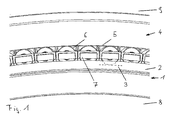
図1は、本発明により形成された円錐ころ軸受けの実施の形態を斜視図で示している。 FIG. 1 is a perspective view showing an embodiment of a tapered roller bearing formed according to the present invention.
円錐ころ軸受けは、当接つば2および円錐形の内側の転動体軌道3を備えた内輪1を有している。図1の図面では、内側の転動体軌道3は当接つば2により覆い隠されている。さらに、円錐ころ軸受けは、円錐形の外側の転動体軌道5を備えた外輪4を有している。さらに、円錐ころ軸受けは、円錐形の転動体6のセットを有している。転動体6は、内側の転動体軌道3および外側の転動体軌道5で転動する。この場合、転動体6は、その回転軸線(図示せず)を中心として回転する。この回転軸線に関して、転動体6は回転対称に形成されている。さらに、転動体6は、その回転軸線に関して軸方向で、当接つば2に当接する。さらに円錐ころ軸受けは、複数の保持器セグメント7を有している。保持器セグメント7は、図示の実施の形態では、それぞれ1つの転動体6を収容している。この場合、各転動体6のために、それぞれ1つの保持器セグメント7が存在しているので、個別の保持器セグメント7が、円錐ころ軸受けの周方向でそれぞれ直接に互いに連続していて、それぞれ1つの転動体6を収容している。この場合、隣り合う保持器セグメント7は、それぞれ互いに接触してよい。択一的には、保持器セグメント7が、それぞれ複数の転動体6を収容するように形成されていてもよい。
The tapered roller bearing has an inner ring 1 with an
保持器セグメント7は、転動体によりガイドされている、つまり保持器セグメント7は、転動体6に支持されている。円錐ころ軸受けの大抵の運転状況では、保持器セグメント7は専ら転動体によりガイドされている、つまり、保持器セグメント7と、内側の転動体軌道3または外側の転動体軌道5、または内輪1または外輪4のその他の構成部材との間では接触は生じない。保持器セグメント7の構成の詳細を、図2、図3、図4および図5につき説明する。
The
符号8により示された領域には、シャフトが配置されていてよい。シャフトには、内輪1が被せられている。シャフトは、特に風力発電設備のロータシャフトであってよい。符号9により示された領域には、外輪4を収容するハウジング9が配置されていてよい。ハウジング9は、特に風力発電設備のロータ支承部の構成部材であってよい。
A shaft may be disposed in the region indicated by
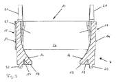
図2は、保持器セグメント7の実施の形態を斜視図で示している。図3および図4はそれぞれ、図2に図示された実施の形態を異なる切断面に関する断面図で示している。図面は、図2〜図4においてそれぞれ、保持器セグメント7が図示の状態で円錐ころ軸受けに組み込まれた場合に、内側の転動体軌道3が保持器セグメント7の下方に延びていて、外側の転動体軌道5が保持器セグメント7の上方に延びているように選択されている。
FIG. 2 shows an embodiment of the
保持器セグメント7は、互いに間隔をおいて配置されかつ互いに対して平行に方向付けられた2つの周方向ウェブ10を有している。これらの周方向ウェブ10は、保持器セグメント7の組込み状態において、円錐ころ軸受けの周方向に延びている。
The
さらに保持器セグメント7は、互いに間隔をおいて配置された2つの結合ウェブ11を有している。これらの結合ウェブ11は、互いに対してゼロとは異なる角度を成しており、かつ2つの周方向ウェブ10を互いに結合している。これによって、転動体6を収容するための1つのポケット12が形成される。これらの結合ウェブ11が平行に延びていない結果、両周方向ウェブ10は、互いに異なる長さを有していて、ポケット12は、等脚台形の形状を有している。保持器セグメント7の第1の周方向端部13から第2の周方向端部14までの周方向ウェブ10の外側寸法が、周方向ウェブ10の長さと見なされる。周方向ウェブ10の第1の周方向端部13と第2の周方向端部14がそれぞれ互いに対して平行に方向付けられていない場合、外側寸法の算術平均値がそれぞれ利用される。図2では、手前側に図示された周方向ウェブ10は、後方に図示された周方向ウェブ10よりも長い。
Furthermore, the
ポケット12を画定する周方向ウェブ10および結合ウェブ11の面を、以下にポケット面と呼ぶ。同様に、周方向ウェブ10および結合ウェブ11の、ポケット面とは反対の側に位置する面を、これらの面が別のポケット12を画定しない限り、以下に周囲面と呼ぶ。周方向ウェブ10ではこの条件は、複数の転動体6が軸方向で相前後して配置される複列の保持器セグメント7の場合を除いて、概して満たされる。結合ウェブ11では、この条件は、各結合ウェブ11が、保持器セグメント7の第1の周方向端部13または第2の周方向端部14の領域に配置されている場合、つまり保持器セグメント7の、円錐ころ軸受けの周方向に関して最初の結合ウェブ11および最後の結合ウェブ11のために満たされている。保持器セグメント7の、図2から図4に示された実施の形態は、唯1つのポケット12しか有していないので、各周方向ウェブ10および各結合ウェブ11が、本実施の形態では、それぞれ1つのポケット面および1つの周囲面を有している。
The surfaces of the circumferential web 10 and the connecting web 11 that define the
既に述べたように、保持器セグメント7が2つ以上のポケットを有している場合でも、単列の保持器セグメント7の周方向ウェブ10はそれぞれ1つのポケット面および1つの周囲面を有している。これに対して、上記のような場合、結合ウェブ11は、それぞれ1つのポケット面および1つの周囲面を有しているか、または2つのポケット面を有し、したがって周囲面を有していない。2つのポケット12の間に配置された結合ウェブ11は、2つのポケット面を有しているが、周囲面を有していない。唯1つのポケット12しか画定していない、周方向で末端の結合ウェブ11は、1つのポケット面および1つの周囲面を有している。
As already mentioned, even if the
周方向ウェブ10および結合ウェブ11は、ポケット面および場合によっては周囲面の他に、内側の軌道面と外側の軌道面とをそれぞれ有している。内側の軌道面は、組込まれた状態で、円錐ころ軸受けの内側の転動体軌道3に面している。外側の軌道面は、組込まれた状態で、円錐ころ軸受けの外側の転動体軌道5に面している。図2から図4では、内側の軌道面は、周方向ウェブ10および結合ウェブ11の下面にそれぞれ一致し、外側の軌道面は、周方向ウェブ10および結合ウェブ11の上面にそれぞれ一致する。
The circumferential web 10 and the connecting web 11 each have an inner track surface and an outer track surface in addition to the pocket surface and possibly the peripheral surface. The inner raceway surface faces the rolling
保持器セグメント7の、図2から図4に図示された実施の形態では、周方向ウェブ10および結合ウェブ11の内側の軌道面および外側の軌道面は、それぞれ平坦な面として形成されている。さらに、周方向ウェブ10および結合ウェブ11の全ての内側の軌道面はそれぞれ、1つの共通の平面の構成部分として形成された部分面を有している。同様に周方向ウェブ10および結合ウェブ11の全ての外側の軌道面はそれぞれ、1つの共通の平面の構成部分として形成された部分面を有している。保持器セグメント7が複数のポケット12を有している実施の形態では、このことは少なくとも、周方向ウェブ10の内側の軌道面および外側の軌道面および同一のポケット12を画定する結合ウェブ11の内側の軌道面および外側の軌道面にそれぞれ適用される。
In the embodiment illustrated in FIGS. 2 to 4 of the
周方向ウェブ10は、特に結合ウェブ11と一体的に、つまりワンピースに形成されている。この一体的な構成は、たとえば、プラスチック射出成形部分としての保持器セグメント7の製造により達成され得る。さらに、周方向ウェブ10および結合ウェブ11は、第1の周方向端部13および第2の周方向端部14の領域において、その周囲面で面が揃うように互いに移行している。つまり、周方向ウェブ10は、結合ウェブ11を超えて外方に向かって突出せず、結合ウェブ11も、周方向ウェブ10を超えて外方に向かって突出することはない。
The circumferential web 10 is in particular formed integrally with the connecting web 11, ie in one piece. This integral configuration can be achieved, for example, by the manufacture of the
周方向ウェブ10の周囲面は、それぞれ1つの大面積の凹設部15を有している。この凹設部15は、周囲面の大部分にわたって延びており、3つの側でU字形に縁取りされている。周方向ウェブ10の下側の軌道面に向かって、凹設部15はそれぞれ開いている。凹設部15を除いて、周方向ウェブ10はそれぞれ、ほぼ四角形の横断面を有している。
The peripheral surface of the circumferential web 10 has one large area recessed
結合ウェブ11のポケット面は、保持器セグメント7内に配置された転動体6において該保持器セグメント7を滑りガイドするためのそれぞれ1つの第1のガイド面16を有している。さらに、結合ウェブ11のポケット面は、保持器セグメント7内に配置された転動体6において保持器セグメント7を滑りガイドするためのそれぞれ1つの第2のガイド面17を有している。円錐ころ軸受けの運転状態において、保持器セグメント7の変形なく、転動体6の外周面に接触することができる領域のみが、それぞれ第1のガイド面16および第2のガイド面17と見なされる。第1のガイド面16および第2のガイド面17は、それぞれ結合ウェブ11の全長にわたって延びているのではなく、たとえば結合ウェブ11の長さの最大で半分にわたる部分領域にわたって延びているだけである。周方向ウェブ10間の結合ウェブ11の全体的な延在長さが結合ウェブ11の長さであると見なされる。この場合、第1のガイド面16と第2のガイド面17とが結合ウェブ11の長手方向に沿って互いにオーバラップしないか、僅かにしかオーバラップしないように、第2のガイド面17は、それぞれ第1のガイド面16の隣に配置されている。言い換えると、第1のガイド面16および第2のガイド面17は、保持器セグメント7内に配置された転動体6の、互いにオーバラップしないか、または単に部分的に、特に僅かにしか互いにオーバラップしない軸方向領域に形成されている。たとえば、第1のガイド面16と第2のガイド面17とは、結合ウェブ11の長さの50%未満、特に10%未満だけオーバラップする。第1のガイド面16は、長短2つの周方向ウェブ10のうちのより長い周方向ウェブ10に接しているか、またはより長い周方向ウェブ10の近傍に配置されており、第2のガイド面17は、より短い周方向ウェブ10に隣接するか、またはより短い周方向ウェブ10の近傍に配置されている。言い換えると、第1のガイド面16は、より長い周方向ウェブ10に対して、第2のガイド面17よりも近接して配置されており、第2のガイド面17は、より短い周方向ウェブ10に対して、第1のガイド面16よりも近接して配置されている。
The pocket surface of the connecting web 11 has a respective
第1のガイド面16および第2のガイド面17は、それぞれ凹状の形状を有しているので、保持器セグメント7のポケット12内に配置された1つの転動体6を周方向でそれぞれ部分的に取り囲んでいる。
Since each of the
さらに、第1のガイド面16と第2のガイド面17とがポケット12内に配置された1つの転動体6を互いに異なる周方向領域でガイドするか、もしくは逆に見て、第1のガイド面16と第2のガイド面17とが転動体6の互いに異なる周方向領域に支持されているように、第1のガイド面16と第2のガイド面17とは、それぞれ互いに対してずらされて配置されている。特に、互いに異なる周方向領域は、互いにオーバラップしないか、僅かにしかオーバラップしていない。たとえば、周方向領域は、転動体6の最大全周の5%未満、有利には1%未満だけオーバラップしてよい。図示された実施の形態では、第1のガイド面16は、内側の軌道面に接近し、かつ該内側の軌道面を超えるにつれてますます互いに接近するように突出し、第2のガイド面17は、外側の軌道面に接近するにつれてますます互いに接近するように突出する。したがって、第1のガイド面16および第2のガイド面17は、上記の方向での進行時に一層ポケット12の領域に突入する。このことは、ポケット12内に挿入された転動体6が、第1のガイド面16によって内側の軌道面に向かってポケット12からの脱落を防止されていて、第2のガイド面17によって外側の軌道面に向かってポケット12からの脱落を防止されていることを意味する。したがって、転動体6は、全ての側に向かって脱落を防止されており、したがって、紛失防止されて保持器セグメント7のポケット12内に配置されている。
Further, the
図2および図3から判るように、第1のガイド面16は、第2のガイド面17に比べて明らかに大きく張り出すように成形されている。第1のガイド面16の大きく張り出した成形を可能にするために、結合ウェブ11にウェブ延長部18が形成されている。ウェブ延長部18は、内側の軌道面を超えて突出し、該内側の軌道面から離れるにつれて徐々に厚くなる。ウェブ延長部18は、中空室19を有している。中空室19は、ウェブ延長部18の自由端に向かって開いている。この中空室19により、ウェブ延長部18の材料厚さは減じられかつ保持器セグメント7の別の領域の材料厚さに近づけられる。
As can be seen from FIG. 2 and FIG. 3, the
さらに、ウェブ延長部18の自由端の領域には、第1の突起20が形成されている。この突起20は、ウェブ延長部18の端部面を超えて突出している。結合ウェブ11の軌道面には、第2のガイド面17が形成されている領域において、第2の突起21が配置されている。保持器セグメント7の組込み状態で、第1の突起20は、内側の転動体軌道3に向かう方向に延びていているが、円錐ころ軸受けが標準条件で回転している場合には、内側の転動体軌道3に接触しない。同様に、第2の突起21は、外側の転動体軌道5に向かう方向に延びているが、円錐ころ軸受けが標準条件で回転している場合には、該外側の転動体軌道5には接触しない。これに対して、円錐ころ軸受けが強い衝撃的な負荷にさらされている場合、第1の突起20と内側の転動体軌道3との間または第2の突起21と外側の転動体軌道5との間で接触が生じ得る。同様のことは、円錐ころ軸受けが回転しない場合にも当てはまる。
Furthermore, a
円錐ころ軸受け内への正しい位置での組込みを容易にするために、保持器セグメント7は、凹設部15の領域にマーキング22を有している。マーキング22は省略することもできる。
The
さらに、保持器セグメント7は、第1の位置決め補助部23および第2の位置決め補助部24を有している。これらの位置決め補助部23,24は、円錐ころ軸受けの組立て時に保持器セグメント7の正しい位置での配置を容易にする。第1の位置決め補助部23は、保持器セグメント7の第1の周方向端部13の領域に配置されている。第2の位置決め補助部24は、保持器セグメント7の第2の周方向端部14の領域に配置されている。
Furthermore, the
第1の位置決め補助部23は、細長い隆起部として形成されていてよい。細長い隆起部は、複数の結合ウェブ11のうちの1つの結合ウェブ11に末端部で配置されており、周方向ウェブ10と面一に整合している。隆起部は、結合ウェブ11の内側の軌道面と外側の軌道面との間の全領域にわたって延びていてよい。
The first
第2の位置決め補助部24は、細長い切欠きとして、特に段部として形成されていてよい。切欠きもしくは段部は、複数の結合ウェブ11のうちの1つの結合ウェブ11に末端部で配置されており、周方向ウェブ10に面一に整合している。隆起部と同様に、切欠きも、結合ウェブ11の内側の軌道面と外側の軌道面との間の全領域にわたって延びていてよい。
The
第1の位置決め補助部23および第2の位置決め補助部24については、図5の図面とは異なる実施の形態も考えられる。この場合、第1の位置決め補助部23および第2の位置決め補助部24は、特に互いに対して相補的に形成されていてよい。さらに、第1の位置決め補助部23と第2の位置決め補助部24との寸法は、第1の位置決め補助部23および第2の位置決め補助部24が互いに係合することができるように、互いに対して調整されていてよい。
Regarding the first
保持器セグメント7の組付け時に、該保持器セグメント7の第1の位置決め補助部23は、既に正しい位置に配置された別の保持器セグメント7の第2の位置決め補助部24と協働し、これにより新たに組み付けられた保持器セグメント7の、正しい位置での配置が容易に認識可能となる。組付けに関する詳細を、図5につき説明する。
When the
図2から図4に図示された実施の形態とは択一的に、保持器セグメント7は、1つよりも多いポケット12を有していてもよく、相応して複数の転動体6を収容することができる。たとえば、保持器セグメント7は、択一的な実施の形態では、2つの転動体6を収容する2つのポケット12を有していてよい。両ポケット12は、2つの周方向ウェブ10と、3つの結合ウェブ11とにより形成されている。3つの結合ウェブ11のうち、保持器セグメント7の第1の周方向端部13の領域もしくは第2の周方向端部14の領域に形成されている2つの結合ウェブ11は、それぞれ1つのポケット面と1つの周囲面とを有している。末端側の2つの結合ウェブ11の間に配置されている第3の結合ウェブ11は、2つのポケット面を有しており、したがって周囲面を有していない。
As an alternative to the embodiment illustrated in FIGS. 2 to 4, the
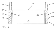
図5は、円錐ころ軸受けの図1に示された実施の形態を、外輪4なしで別の斜視図で示している。図示された配置は、円錐ころ軸受け内への組込み状態に一致する。 FIG. 5 shows the embodiment of the tapered roller bearing shown in FIG. 1 in another perspective view without the outer ring 4. The arrangement shown corresponds to the assembled state in the tapered roller bearing.
異なる保持器セグメント7の周方向ウェブ10は、互いに対してそれぞれ所定の角度を成している。特に、異なる保持器セグメント7の周方向ウェブ10の内側の軌道面はそれぞれ、ゼロとは異なる角度を互いに成している。同様に、異なる保持器セグメント7の周方向ウェブ10の外側の軌道面はそれぞれ、ゼロとは異なる角度を互いに成している。複数のポケット12を有する保持器7の実施の形態では、周方向ウェブ10の内側の軌道面および/または外側の軌道面がそれぞれ1つの多角形形状を有しており、したがって保持器セグメント7の異なるポケット12の領域に配置されている軌道面の区分は、互いに対してゼロとは異なる角度を成している。
The circumferential webs 10 of the
保持器セグメント7の幾何学形状、特に第1のガイド面16と第2のガイド面17との幾何学形状は、保持器セグメント7が、円錐ころ軸受けの回転状態において転動体6に支持され、かつ内側の転動体軌道3にも外側の転動体軌道5にも接触しないように、転動体6に合わせて適合されている。このことは、円錐ころ軸受けが、転動体6によりガイドされていることを意味している。しかし、内側の転動体軌道3と、保持器セグメント7の第1の突起20との間で、かつ外側の転動体軌道5と、保持器セグメント7の第2の突起21との間では、それぞれ小さな内法の間隔が形成されており、これにより強い衝撃状の負荷がかけられた場合または円錐ころ軸受けの静止状態において、保持器セグメント7と内側の転動体軌道3または外側の転動体軌道5との間の接触が生じることがある。この接触は、保持器セグメント7の第1の突起20または第2の突起21の領域で発生するので、保持器セグメント7は、このような状態では第1の突起20で内側の転動体軌道3に支持されるか、第2の突起21で外側の転動体軌道5に支持される。この特別な状態が終了すると、内側の転動体軌道3または外側の転動体軌道5との保持器セグメント7の接触も再び解消され、再び純粋な転動体によるガイドが行われる。このことは、第1の突起20および第2の突起21に、極端な状態での保持器セグメント7の支持機能を付け加えることを意味する。この支持機能は、保持器セグメント7の過剰な摩耗時にも設けられている。これにより、保持器セグメント7の、もはや十分な程度ではなくなった転動体ガイドを代替することができる。
The geometric shape of the
図5からさらに、各保持器セグメント7の、それぞれ隆起部として形成された第1の位置決め補助部23が、それぞれ隣接する保持器セグメント7の、それぞれ切欠きとして形成された第2の位置決め補助部24にどのように係合するかが明らかになる。この場合、互いに隣り合う保持器セグメント7は、それぞれ周方向でその第1の周方向端部13とその第2の周方向端部14の領域で接触する。隣り合う保持器セグメント7がたとえば互いに対して180°だけ反転して配置されている場合、第1の位置決め補助部23および第2の位置決め補助部24は互いに係合することができない。したがって、円錐ころ軸受けの組立て時に、反転して挿入された保持器セグメント7は直ぐに目につく。正しい位置での組付けの支援に対して付加的に、第1の位置決め補助部23および第2の位置決め補助部24の別の機能は、保持器セグメント7が互いに相対的に移動することを防止することにある。
Further, from FIG. 5, the first positioning
転がり軸受けの組立てのために、保持器セグメント7には、まず、それぞれ1つの転動体6が装着される。次いで転動体6を装着された保持器セグメント7は、相並んで内側の転動体軌道3に配置される。有利には、保持器セグメント7は個別にかつ順次に組み付けられる。
For assembling the rolling bearings, first, one rolling
組立て終了後に、全体的な保持器セグメント7は、互いに接触して並べられていて、これにより隣り合う保持器セグメント7が、最初の保持器セグメント7および最後の保持器セグメント7を除いて接触している場合、最初の保持器セグメントの第1の周方向端部13と最後の保持器セグメント7の第2の周方向端部14との間の平均的な内法の間隔は、位置決め補助部23,24外で、ピッチ円の円周の少なくとも0.15%および最大で1%である。平均的な内法の間隔は、特に算術平均により規定されていてよい。ピッチ円は、特に、該ピッチ円が、転動体6の回転軸線にそれぞれ転動体6の軸方向の中心で交差することにより定義されている。
After assembly, the
1 内輪
2 当接つば
3 内側の転動体軌道
4 外輪
5 外側の転動体軌道
6 転動体
7 保持器セグメント
8 シャフトの領域
9 ハウジングの領域
10 周方向ウェブ
11 結合ウェブ
12 ポケット
13 第1の周方向端部
14 第2の周方向端部
15 凹設部
16 第1のガイド面
17 第2のガイド面
18 ウェブ延長部
19 中空室
20 第1の突出部
21 第2の突出部
22 マーキング
23 第1の位置決め補助部
24 第2の位置決め補助部
DESCRIPTION OF SYMBOLS 1
本発明は、円錐ころ軸受けの保持器セグメントに関する。さらに、本発明は、第1の機械部分を、第2の機械部分に対して回転可能に支承する、特に風力発電設備のロータシャフトを回転可能に支承する円錐ころ軸受けと、円錐ころ軸受けを組み立てる方法とに関する。 The present invention relates to a cage segment of a tapered roller bearing. Furthermore, the present invention assembles a tapered roller bearing and a tapered roller bearing that rotatably supports the first machine part relative to the second machine part, in particular, rotatably supports the rotor shaft of the wind power generation facility. With respect to methods.
このような保持器セグメントは、独国特許出願公開第10246825号明細書から公知である。公知の保持器セグメントは、その端面で互いに接して並べられ得るので、比較的小さな手間で、比較的小さなころを有する極めて大きな転がり軸受けでの使用のために特に適している保持器が形成され得る。 Such a cage segment is known from DE 102 46 825 A1. The known cage segments can be arranged in contact with each other at their end faces, so that cages can be formed that are particularly suitable for use with very large rolling bearings with relatively small rollers, with relatively little effort. .
特開2008−82380号から公知の保持器セグメントは、転動体を保持器セグメントに位置固定するために固形潤滑剤を有している。 A cage segment known from JP 2008-82380 has a solid lubricant for fixing the rolling elements to the cage segment.
たとえば風力発電設備に用いられる一層大型化する転がり軸受けに対する需要が高まっていることに際して、一層高い機械的な負荷のための保持器設計が必要とされる。転がり軸受けのサイズと共に、使用される転動体の自重もますます増大し、この理由からも、一層安定的な保持器配列が必要とされる。 For example, as the demand for larger rolling bearings used in wind power generation facilities increases, cage designs for higher mechanical loads are required. Along with the size of the rolling bearing, the dead weight of the rolling elements used is also increasing, and for this reason, a more stable cage arrangement is required.
本発明の根底を成す課題は、極めて大きな転がり軸受け、特に風力発電設備の転がり軸受けでの使用に適していて、かつ転がり軸受けの簡単な組立てを可能にする保持器の設計を提供することにある。 The problem underlying the present invention is to provide a cage design which is suitable for use in very large rolling bearings, in particular in rolling bearings of wind power plants, and which allows simple assembly of the rolling bearings. .
この課題は、複数の独立請求項に記載された特徴の組合せにより解決される。 This problem is solved by a combination of features described in the independent claims.
第1の機械部分を、第2の機械部分に対して回転可能に支承する円錐ころ軸受けの、本発明に係る保持器セグメントは、相互に向かい合う2つの周方向ウェブを有している。これらの周方向ウェブは、保持器セグメントの第1の周方向端部と第2の周方向端部との間にそれぞれ延びている。保持器セグメントは、さらに相互に向かい合う少なくとも2つの結合ウェブを有している。これらの結合ウェブは、両周方向ウェブを互いに結合し、該周方向ウェブと一緒に、円錐形の転動体を収容するための少なくとも1つのポケットを形成している。周方向ウェブおよび結合ウェブは、ポケットを画定するポケット面を有している。結合ウェブのポケット面はそれぞれ、1つの転動体を該転動体の周方向で部分的に取り囲むための、凹状に成形された第1のガイド面と、凹状に成形された第2のガイド面とを有している。周方向ウェブと、第1の周方向端部および第2の周方向端部の領域に配置された結合ウェブとは、ポケット面とは反対の側に位置する周囲面を有している。保持器セグメントは、第1の周方向端部の領域で第1の位置決め補助部を有しており、第2の周方向端部の領域で第2の位置決め補助部を有している。円錐ころ軸受けにおいて隣り合う保持器セグメントの、互いに相対的に正しい位置での配置が、保持器セグメントの第1の位置決め補助部と第2の位置決め補助部との協働に基づいて認識可能であるように、第1の位置決め補助部と第2の位置決め補助部とは互いに相対的に配置されている。保持器セグメントは、転動体によりガイドされている。 The retainer segment according to the invention of a tapered roller bearing for rotatably supporting a first mechanical part with respect to a second mechanical part has two circumferential webs facing each other. These circumferential webs each extend between a first circumferential end and a second circumferential end of the cage segment. The cage segment further has at least two bonded webs facing each other. These connecting webs connect the two circumferential webs to one another and together with the circumferential web form at least one pocket for receiving a conical rolling element. The circumferential web and the connecting web have a pocket surface that defines a pocket. Each of the pocket surfaces of the connecting web includes a first guide surface formed into a concave shape and a second guide surface formed into a concave shape so as to partially surround one rolling member in the circumferential direction of the rolling member. have. The circumferential web and the connecting web disposed in the region of the first circumferential end and the second circumferential end have a peripheral surface located on the opposite side of the pocket surface. The cage segment has a first positioning assist in the region of the first circumferential end and a second positioning assist in the region of the second circumferential end. The arrangement of adjacent cage segments in the tapered roller bearings at correct positions relative to each other is recognizable based on the cooperation of the first positioning aid and the second positioning aid of the cage segment. Thus, the 1st positioning auxiliary | assistant part and the 2nd positioning auxiliary | assistant part are arrange | positioned relatively mutually. The cage segment is guided by rolling elements.
本発明は、円錐ころ軸受けの組立て時に保持器セグメントの誤った方向付けが極めて容易に認識され得ることを、比較的に小さな手間で達成されるという利点を有している。これによって、保持器セグメントの誤った方向付けより生じる組立てエラーが高い信頼性で阻止され得る。 The invention has the advantage that a relatively small effort is achieved that the incorrect orientation of the cage segments can be recognized very easily when the tapered roller bearings are assembled. This can reliably prevent assembly errors resulting from incorrect orientation of the cage segments.
第1の位置決め補助部および第2の位置決め補助部は、互いに対して相補的に形成されていてよい。これにより、保持器セグメントの位置のずれにより生じる、位置決め補助部の協働の不良は、極めて明らかに認識可能となる。 The 1st positioning auxiliary | assistant part and the 2nd positioning auxiliary | assistant part may be formed complementarily with respect to each other. As a result, the poor cooperation of the positioning aids caused by the displacement of the cage segments can be recognized very clearly.
第1の位置決め補助部と第2の位置決め補助部とは、同じ程度だけ偏心して結合ウェブの周囲面に配置されていてよい。特に、第1の位置決め補助部と第2の位置決め補助部とは、結合ウェブの周囲面の両端部に配置されていてよい。 The first positioning auxiliary part and the second positioning auxiliary part may be eccentrically arranged by the same degree and arranged on the peripheral surface of the coupling web. In particular, the first positioning auxiliary part and the second positioning auxiliary part may be arranged at both ends of the peripheral surface of the connecting web.
第1の位置決め補助部と第2の位置決め補助部とはそれぞれ、各結合ウェブの周囲面の、周方向ウェブとオーバラップしている区分に配置されていてよい。このことは、結合ウェブが、位置決め補助部の領域において、周方向ウェブにより支持され、位置決め補助部により生じ得る材料弱化部が不都合な作用を有しない、という利点を有している。 Each of the first positioning assisting portion and the second positioning assisting portion may be arranged in a section of the peripheral surface of each connecting web that overlaps the circumferential web. This has the advantage that the connecting web is supported by the circumferential web in the region of the positioning aid and the material weakening that can be caused by the positioning aid does not have an adverse effect.
たとえば、第1の位置決め補助部が、結合ウェブの周囲面を周方向で超えて突出する隆起部として形成されており、第2の位置決め補助部が、切欠きとして形成されていてよい。このような構成は、容易に製造可能であり、円錐ころ軸受けの運転の妨害をもたらさない。さらに、保持器セグメントの正しい位置での配置を良好に認識することができる。特に第2の位置決め補助部は、段部として形成されていてよい。 For example, the 1st positioning auxiliary | assistant part may be formed as the protruding part which protrudes beyond the surrounding surface of a joint web in the circumferential direction, and the 2nd positioning auxiliary | assistant part may be formed as a notch. Such a configuration is easily manufacturable and does not interfere with the operation of the tapered roller bearing. Furthermore, the arrangement of the cage segments at the correct positions can be recognized well. In particular, the second positioning assisting part may be formed as a step part.
隣り合った保持器セグメントを互いに相対的に正しい位置で配置する場合、隣り合った保持器セグメントの第1の位置決め補助部と第2の位置決め補助部とは互いに係合することができる。第1の位置決め補助部および第2の位置決め補助部は、隣り合った保持器セグメントが正しく配置されているときにだけ第1の位置決め補助部および第2の位置決め補助部が互いに係合するように、形成されている。特に、正しい位置での配置時には、隣り合った保持器セグメントの隆起部と切欠きとが、互いに係合することができる。 When the adjacent cage segments are arranged at correct positions relative to each other, the first positioning auxiliary portion and the second positioning auxiliary portion of the adjacent cage segments can be engaged with each other. The first positioning auxiliary portion and the second positioning auxiliary portion are arranged so that the first positioning auxiliary portion and the second positioning auxiliary portion engage with each other only when adjacent cage segments are correctly arranged. Is formed. In particular, when placed in the correct position, the ridges and notches of adjacent cage segments can engage each other.
保持器セグメントは、まさに1つのポケットを有していてよい。このことは、保持器セグメントが機械的に特に安定的であるという利点を有している。 The cage segment may have exactly one pocket. This has the advantage that the cage segment is mechanically particularly stable.
全ての結合ウェブは、そのポケット面で同一に形成されていてよい。周方向ウェブはそれぞれ、複数の結合ウェブのうちの1つの結合ウェブで開始し、結合ウェブのうちの1つの結合ウェブで終了していてよい。第1のガイド面と第2のガイド面とは、同一の結合ウェブのポケット面において、ポケット内に配置された転動体を、互いに異なる周方向領域でかつ/または互いに異なる軸方向領域で取り囲むことができる。結合ウェブには、円錐ころ軸受けの内側の転動体軌道で保持器セグメントを支持するための第1の突起および/または円錐ころ軸受けの外側の転動体軌道で保持器セグメントを支持するための第2の突起が形成されていてよい。第1の突起が両周方向ウェブの間で延びている第1の領域と、第2の突起が両周方向ウェブの間で延びている第2の領域とが互いにオーバラップしないように、保持器セグメントが形成されていてよい。 Bonded web of full hand, may be formed on the same in the pocket surface. Each circumferential web may start with one of the plurality of bonded webs and end with one of the bonded webs. The first guide surface and the second guide surface surround the rolling elements disposed in the pocket in different pocket regions of the same connecting web in different circumferential regions and / or different axial regions. Can do. The coupling web includes a first protrusion for supporting the cage segment on the rolling element raceway inside the tapered roller bearing and / or a second projection for supporting the cage segment on the rolling element raceway outside the tapered roller bearing. The protrusion may be formed. The first region where the first protrusion extends between the two circumferential webs and the second region where the second protrusion extends between the two circumferential webs are held so as not to overlap each other. A vessel segment may be formed.
さらに本発明は、第1の機械部分を第2の機械部分に対して回転可能に支承する円錐ころ軸受けに関する。本発明に係る円錐ころ軸受けは、それぞれ1つの回転軸線を有する円錐形の転動体と、本発明に係る保持器セグメントとを有している。保持器セグメントは、それぞれ少なくとも1つの転動体を収容する。全ての転動体の回転軸線は、1つの共通の円錐面に配置されている。 The invention further relates to a tapered roller bearing for rotatably supporting a first machine part relative to a second machine part. The tapered roller bearing according to the present invention includes conical rolling elements each having one rotational axis, and a cage segment according to the present invention . Retainer segments accommodates at least one rolling element, respectively. The axis of rotation of all the rolling elements, that are disposed on a common conical surface.
保持器セグメントは、円錐ころ軸受けの周方向で直接に互いに対して隣り合って配置されていてよい。円錐ころ軸受けは、隣り合う保持器セグメントが少なくとも時々接触するように形成されていてよい。隣り合う全ての保持器セグメントが、最初の保持器セグメントと最後の保持器セグメントとを除いて接触する場合、最初の保持器セグメントの第1の周方向端部と、最後の保持器セグメントの第2の周方向端部との間の平均的な内法の間隔は、位置決め補助部外で、ピッチ円の円周の少なくとも0.15%かつ最大で1%である。平均的な内法の間隔は、特に算術平均値により規定され得る。ピッチ円は特に、ピッチ円が転動体の回転軸線とそれぞれ転動体の軸方向の中心で交差することにより定義され得る。各保持器セグメントは、まさに1つの転動体を収容している。保持器セグメントは、転動体によりガイドされていてよい。保持器セグメントが互いに機械的に結合されていないことが規定されていてもよい。 The cage segments may be arranged directly next to each other in the circumferential direction of the tapered roller bearing. The tapered roller bearing may be formed such that adjacent cage segments are at least occasionally in contact. When all adjacent cage segments are in contact except for the first and last cage segments, the first circumferential end of the first cage segment and the number of the last cage segment. The average internal spacing between the two circumferential ends is at least 0.15% and at most 1% of the circumference of the pitch circle outside the positioning aid. The average internal spacing can be defined in particular by the arithmetic mean value. The pitch circle can be defined in particular by the intersection of the pitch circle with the axis of rotation of the rolling element, respectively at the axial center of the rolling element. Each cage segment contains exactly one rolling element. The cage segment may be guided by rolling elements. It may be provided that the cage segments are not mechanically coupled to each other.
円錐ころ軸受けは、特に風力発電設備のロータシャフトを回転可能に支承するために働く。 The tapered roller bearing serves in particular to rotatably support the rotor shaft of the wind power plant.
さらに本発明は、円錐ころ軸受けを組み立てる方法に関する。本発明に係る方法では、本発明に係る複数の保持器セグメントを、円錐ころ軸受けの周方向で相並んで位置決めし、隣り合った保持器セグメントの第1の位置決め補助部と第2の位置決め補助部との協働に基づいて、これらの保持器セグメントが互いに相対的に正しい位置に配置されていることが認識可能である。 The invention further relates to a method for assembling a tapered roller bearing. In the method according to the present invention, the plurality of retainer segments according to the present invention are positioned side by side in the circumferential direction of the tapered roller bearing, and the first positioning assisting portion and the second positioning assisting member of the adjacent retainer segments are positioned. Based on the cooperation with the parts, it can be recognized that these cage segments are arranged in the correct position relative to each other.
保持器セグメントには、円錐ころ軸受けにおける位置決めの前に、それぞれ少なくとも1つの転動体が装着され得る。これによって、組立て中の保持器セグメントの機械的な負荷を、小さく維持することができる。転動体を装着された保持器セグメントは、相並んで内側の転動体軌道に配置され得る。特に保持器セグメントは個別にも、相並んでも組み付けられ得る。 Each cage segment can be fitted with at least one rolling element before positioning in the tapered roller bearing. Thereby, the mechanical load of the cage segment during assembly can be kept small. The cage segments fitted with rolling elements can be arranged side by side on the inner rolling element track. In particular, the cage segments can be assembled individually or side by side.
本発明を図面に示した実施の形態につき以下に詳しく説明する。 The present invention will be described in detail below with reference to embodiments shown in the drawings.
図1は、本発明により形成された円錐ころ軸受けの実施の形態を斜視図で示している。 FIG. 1 is a perspective view showing an embodiment of a tapered roller bearing formed according to the present invention.
円錐ころ軸受けは、当接つば2および円錐形の内側の転動体軌道3を備えた内輪1を有している。図1の図面では、内側の転動体軌道3は当接つば2により覆い隠されている。さらに、円錐ころ軸受けは、円錐形の外側の転動体軌道5を備えた外輪4を有している。さらに、円錐ころ軸受けは、円錐形の転動体6のセットを有している。転動体6は、内側の転動体軌道3および外側の転動体軌道5で転動する。この場合、転動体6は、その回転軸線(図示せず)を中心として回転する。この回転軸線に関して、転動体6は回転対称に形成されている。さらに、転動体6は、その回転軸線に関して軸方向で、当接つば2に当接する。さらに円錐ころ軸受けは、複数の保持器セグメント7を有している。保持器セグメント7は、図示の実施の形態では、それぞれ1つの転動体6を収容している。この場合、各転動体6のために、それぞれ1つの保持器セグメント7が存在しているので、個別の保持器セグメント7が、円錐ころ軸受けの周方向でそれぞれ直接に互いに連続していて、それぞれ1つの転動体6を収容している。この場合、隣り合う保持器セグメント7は、それぞれ互いに接触してよい。択一的には、保持器セグメント7が、それぞれ複数の転動体6を収容するように形成されていてもよい。
The tapered roller bearing has an inner ring 1 with an
保持器セグメント7は、転動体によりガイドされている、つまり保持器セグメント7は、転動体6に支持されている。円錐ころ軸受けの大抵の運転状況では、保持器セグメント7は専ら転動体によりガイドされている、つまり、保持器セグメント7と、内側の転動体軌道3または外側の転動体軌道5、または内輪1または外輪4のその他の構成部材との間では接触は生じない。保持器セグメント7の構成の詳細を、図2、図3、図4および図5につき説明する。
The
符号8により示された領域には、シャフトが配置されていてよい。シャフトには、内輪1が被せられている。シャフトは、特に風力発電設備のロータシャフトであってよい。符号9により示された領域には、外輪4を収容するハウジング9が配置されていてよい。ハウジング9は、特に風力発電設備のロータ支承部の構成部材であってよい。
A shaft may be disposed in the region indicated by
図2は、保持器セグメント7の実施の形態を斜視図で示している。図3および図4はそれぞれ、図2に図示された実施の形態を異なる切断面に関する断面図で示している。図面は、図2〜図4においてそれぞれ、保持器セグメント7が図示の状態で円錐ころ軸受けに組み込まれた場合に、内側の転動体軌道3が保持器セグメント7の下方に延びていて、外側の転動体軌道5が保持器セグメント7の上方に延びているように選択されている。
FIG. 2 shows an embodiment of the
保持器セグメント7は、互いに間隔をおいて配置されかつ互いに対して平行に方向付けられた2つの周方向ウェブ10を有している。これらの周方向ウェブ10は、保持器セグメント7の組込み状態において、円錐ころ軸受けの周方向に延びている。
The
さらに保持器セグメント7は、互いに間隔をおいて配置された2つの結合ウェブ11を有している。これらの結合ウェブ11は、互いに対してゼロとは異なる角度を成しており、かつ2つの周方向ウェブ10を互いに結合している。これによって、転動体6を収容するための1つのポケット12が形成される。これらの結合ウェブ11が平行に延びていない結果、両周方向ウェブ10は、互いに異なる長さを有していて、ポケット12は、等脚台形の形状を有している。保持器セグメント7の第1の周方向端部13から第2の周方向端部14までの周方向ウェブ10の外側寸法が、周方向ウェブ10の長さと見なされる。周方向ウェブ10の第1の周方向端部13と第2の周方向端部14がそれぞれ互いに対して平行に方向付けられていない場合、外側寸法の算術平均値がそれぞれ利用される。図2では、手前側に図示された周方向ウェブ10は、後方に図示された周方向ウェブ10よりも長い。
Furthermore, the
ポケット12を画定する周方向ウェブ10および結合ウェブ11の面を、以下にポケット面と呼ぶ。同様に、周方向ウェブ10および結合ウェブ11の、ポケット面とは反対の側に位置する面を、これらの面が別のポケット12を画定しない限り、以下に周囲面と呼ぶ。周方向ウェブ10ではこの条件は、複数の転動体6が軸方向で相前後して配置される複列の保持器セグメント7の場合を除いて、概して満たされる。結合ウェブ11では、この条件は、各結合ウェブ11が、保持器セグメント7の第1の周方向端部13または第2の周方向端部14の領域に配置されている場合、つまり保持器セグメント7の、円錐ころ軸受けの周方向に関して最初の結合ウェブ11および最後の結合ウェブ11のために満たされている。保持器セグメント7の、図2から図4に示された実施の形態は、唯1つのポケット12しか有していないので、各周方向ウェブ10および各結合ウェブ11が、本実施の形態では、それぞれ1つのポケット面および1つの周囲面を有している。
The surfaces of the circumferential web 10 and the connecting web 11 that define the
既に述べたように、保持器セグメント7が2つ以上のポケットを有している場合でも、単列の保持器セグメント7の周方向ウェブ10はそれぞれ1つのポケット面および1つの周囲面を有している。これに対して、上記のような場合、結合ウェブ11は、それぞれ1つのポケット面および1つの周囲面を有しているか、または2つのポケット面を有し、したがって周囲面を有していない。2つのポケット12の間に配置された結合ウェブ11は、2つのポケット面を有しているが、周囲面を有していない。唯1つのポケット12しか画定していない、周方向で末端の結合ウェブ11は、1つのポケット面および1つの周囲面を有している。
As already mentioned, even if the
周方向ウェブ10および結合ウェブ11は、ポケット面および場合によっては周囲面の他に、内側の軌道面と外側の軌道面とをそれぞれ有している。内側の軌道面は、組込まれた状態で、円錐ころ軸受けの内側の転動体軌道3に面している。外側の軌道面は、組込まれた状態で、円錐ころ軸受けの外側の転動体軌道5に面している。図2から図4では、内側の軌道面は、周方向ウェブ10および結合ウェブ11の下面にそれぞれ一致し、外側の軌道面は、周方向ウェブ10および結合ウェブ11の上面にそれぞれ一致する。
The circumferential web 10 and the connecting web 11 each have an inner track surface and an outer track surface in addition to the pocket surface and possibly the peripheral surface. The inner raceway surface faces the rolling
保持器セグメント7の、図2から図4に図示された実施の形態では、周方向ウェブ10および結合ウェブ11の内側の軌道面および外側の軌道面は、それぞれ平坦な面として形成されている。さらに、周方向ウェブ10および結合ウェブ11の全ての内側の軌道面はそれぞれ、1つの共通の平面の構成部分として形成された部分面を有している。同様に周方向ウェブ10および結合ウェブ11の全ての外側の軌道面はそれぞれ、1つの共通の平面の構成部分として形成された部分面を有している。保持器セグメント7が複数のポケット12を有している実施の形態では、このことは少なくとも、周方向ウェブ10の内側の軌道面および外側の軌道面および同一のポケット12を画定する結合ウェブ11の内側の軌道面および外側の軌道面にそれぞれ適用される。
In the embodiment illustrated in FIGS. 2 to 4 of the
周方向ウェブ10は、特に結合ウェブ11と一体的に、つまりワンピースに形成されている。この一体的な構成は、たとえば、プラスチック射出成形部分としての保持器セグメント7の製造により達成され得る。さらに、周方向ウェブ10および結合ウェブ11は、第1の周方向端部13および第2の周方向端部14の領域において、その周囲面で面が揃うように互いに移行している。つまり、周方向ウェブ10は、結合ウェブ11を超えて外方に向かって突出せず、結合ウェブ11も、周方向ウェブ10を超えて外方に向かって突出することはない。
The circumferential web 10 is in particular formed integrally with the connecting web 11, ie in one piece. This integral configuration can be achieved, for example, by the manufacture of the
周方向ウェブ10の周囲面は、それぞれ1つの大面積の凹設部15を有している。この凹設部15は、周囲面の大部分にわたって延びており、3つの側でU字形に縁取りされている。周方向ウェブ10の下側の軌道面に向かって、凹設部15はそれぞれ開いている。凹設部15を除いて、周方向ウェブ10はそれぞれ、ほぼ四角形の横断面を有している。
The peripheral surface of the circumferential web 10 has one large area recessed
結合ウェブ11のポケット面は、保持器セグメント7内に配置された転動体6において該保持器セグメント7を滑りガイドするためのそれぞれ1つの第1のガイド面16を有している。さらに、結合ウェブ11のポケット面は、保持器セグメント7内に配置された転動体6において保持器セグメント7を滑りガイドするためのそれぞれ1つの第2のガイド面17を有している。円錐ころ軸受けの運転状態において、保持器セグメント7の変形なく、転動体6の外周面に接触することができる領域のみが、それぞれ第1のガイド面16および第2のガイド面17と見なされる。第1のガイド面16および第2のガイド面17は、それぞれ結合ウェブ11の全長にわたって延びているのではなく、たとえば結合ウェブ11の長さの最大で半分にわたる部分領域にわたって延びているだけである。周方向ウェブ10間の結合ウェブ11の全体的な延在長さが結合ウェブ11の長さであると見なされる。この場合、第1のガイド面16と第2のガイド面17とが結合ウェブ11の長手方向に沿って互いにオーバラップしないか、僅かにしかオーバラップしないように、第2のガイド面17は、それぞれ第1のガイド面16の隣に配置されている。言い換えると、第1のガイド面16および第2のガイド面17は、保持器セグメント7内に配置された転動体6の、互いにオーバラップしないか、または単に部分的に、特に僅かにしか互いにオーバラップしない軸方向領域に形成されている。たとえば、第1のガイド面16と第2のガイド面17とは、結合ウェブ11の長さの50%未満、特に10%未満だけオーバラップする。第1のガイド面16は、長短2つの周方向ウェブ10のうちのより長い周方向ウェブ10に接しているか、またはより長い周方向ウェブ10の近傍に配置されており、第2のガイド面17は、より短い周方向ウェブ10に隣接するか、またはより短い周方向ウェブ10の近傍に配置されている。言い換えると、第1のガイド面16は、より長い周方向ウェブ10に対して、第2のガイド面17よりも近接して配置されており、第2のガイド面17は、より短い周方向ウェブ10に対して、第1のガイド面16よりも近接して配置されている。
The pocket surface of the connecting web 11 has a respective
第1のガイド面16および第2のガイド面17は、それぞれ凹状の形状を有しているので、保持器セグメント7のポケット12内に配置された1つの転動体6を周方向でそれぞれ部分的に取り囲んでいる。
Since each of the
さらに、第1のガイド面16と第2のガイド面17とがポケット12内に配置された1つの転動体6を互いに異なる周方向領域でガイドするか、もしくは逆に見て、第1のガイド面16と第2のガイド面17とが転動体6の互いに異なる周方向領域に支持されているように、第1のガイド面16と第2のガイド面17とは、それぞれ互いに対してずらされて配置されている。特に、互いに異なる周方向領域は、互いにオーバラップしないか、僅かにしかオーバラップしていない。たとえば、周方向領域は、転動体6の最大全周の5%未満、有利には1%未満だけオーバラップしてよい。図示された実施の形態では、第1のガイド面16は、内側の軌道面に接近し、かつ該内側の軌道面を超えるにつれてますます互いに接近するように突出し、第2のガイド面17は、外側の軌道面に接近するにつれてますます互いに接近するように突出する。したがって、第1のガイド面16および第2のガイド面17は、上記の方向での進行時に一層ポケット12の領域に突入する。このことは、ポケット12内に挿入された転動体6が、第1のガイド面16によって内側の軌道面に向かってポケット12からの脱落を防止されていて、第2のガイド面17によって外側の軌道面に向かってポケット12からの脱落を防止されていることを意味する。したがって、転動体6は、全ての側に向かって脱落を防止されており、したがって、紛失防止されて保持器セグメント7のポケット12内に配置されている。
Further, the
図2および図3から判るように、第1のガイド面16は、第2のガイド面17に比べて明らかに大きく張り出すように成形されている。第1のガイド面16の大きく張り出した成形を可能にするために、結合ウェブ11にウェブ延長部18が形成されている。ウェブ延長部18は、内側の軌道面を超えて突出し、該内側の軌道面から離れるにつれて徐々に厚くなる。ウェブ延長部18は、中空室19を有している。中空室19は、ウェブ延長部18の自由端に向かって開いている。この中空室19により、ウェブ延長部18の材料厚さは減じられかつ保持器セグメント7の別の領域の材料厚さに近づけられる。
As can be seen from FIG. 2 and FIG. 3, the
さらに、ウェブ延長部18の自由端の領域には、第1の突起20が形成されている。この突起20は、ウェブ延長部18の端部面を超えて突出している。結合ウェブ11の軌道面には、第2のガイド面17が形成されている領域において、第2の突起21が配置されている。保持器セグメント7の組込み状態で、第1の突起20は、内側の転動体軌道3に向かう方向に延びていているが、円錐ころ軸受けが標準条件で回転している場合には、内側の転動体軌道3に接触しない。同様に、第2の突起21は、外側の転動体軌道5に向かう方向に延びているが、円錐ころ軸受けが標準条件で回転している場合には、該外側の転動体軌道5には接触しない。これに対して、円錐ころ軸受けが強い衝撃的な負荷にさらされている場合、第1の突起20と内側の転動体軌道3との間または第2の突起21と外側の転動体軌道5との間で接触が生じ得る。同様のことは、円錐ころ軸受けが回転しない場合にも当てはまる。
Furthermore, a
円錐ころ軸受け内への正しい位置での組込みを容易にするために、保持器セグメント7は、凹設部15の領域にマーキング22を有している。マーキング22は省略することもできる。
The
さらに、保持器セグメント7は、第1の位置決め補助部23および第2の位置決め補助部24を有している。これらの位置決め補助部23,24は、円錐ころ軸受けの組立て時に保持器セグメント7の正しい位置での配置を容易にする。第1の位置決め補助部23は、保持器セグメント7の第1の周方向端部13の領域に配置されている。第2の位置決め補助部24は、保持器セグメント7の第2の周方向端部14の領域に配置されている。
Furthermore, the
第1の位置決め補助部23は、細長い隆起部として形成されていてよい。細長い隆起部は、複数の結合ウェブ11のうちの1つの結合ウェブ11に末端部で配置されており、周方向ウェブ10と面一に整合している。隆起部は、結合ウェブ11の内側の軌道面と外側の軌道面との間の全領域にわたって延びていてよい。
The first
第2の位置決め補助部24は、細長い切欠きとして、特に段部として形成されていてよい。切欠きもしくは段部は、複数の結合ウェブ11のうちの1つの結合ウェブ11に末端部で配置されており、周方向ウェブ10に面一に整合している。隆起部と同様に、切欠きも、結合ウェブ11の内側の軌道面と外側の軌道面との間の全領域にわたって延びていてよい。
The
第1の位置決め補助部23および第2の位置決め補助部24については、図5の図面とは異なる実施の形態も考えられる。この場合、第1の位置決め補助部23および第2の位置決め補助部24は、特に互いに対して相補的に形成されていてよい。さらに、第1の位置決め補助部23と第2の位置決め補助部24との寸法は、第1の位置決め補助部23および第2の位置決め補助部24が互いに係合することができるように、互いに対して調整されていてよい。
Regarding the first
保持器セグメント7の組付け時に、該保持器セグメント7の第1の位置決め補助部23は、既に正しい位置に配置された別の保持器セグメント7の第2の位置決め補助部24と協働し、これにより新たに組み付けられた保持器セグメント7の、正しい位置での配置が容易に認識可能となる。組付けに関する詳細を、図5につき説明する。
When the
図2から図4に図示された実施の形態とは択一的に、保持器セグメント7は、1つよりも多いポケット12を有していてもよく、相応して複数の転動体6を収容することができる。たとえば、保持器セグメント7は、択一的な実施の形態では、2つの転動体6を収容する2つのポケット12を有していてよい。両ポケット12は、2つの周方向ウェブ10と、3つの結合ウェブ11とにより形成されている。3つの結合ウェブ11のうち、保持器セグメント7の第1の周方向端部13の領域もしくは第2の周方向端部14の領域に形成されている2つの結合ウェブ11は、それぞれ1つのポケット面と1つの周囲面とを有している。末端側の2つの結合ウェブ11の間に配置されている第3の結合ウェブ11は、2つのポケット面を有しており、したがって周囲面を有していない。
As an alternative to the embodiment illustrated in FIGS. 2 to 4, the
図5は、円錐ころ軸受けの図1に示された実施の形態を、外輪4なしで別の斜視図で示している。図示された配置は、円錐ころ軸受け内への組込み状態に一致する。 FIG. 5 shows the embodiment of the tapered roller bearing shown in FIG. 1 in another perspective view without the outer ring 4. The arrangement shown corresponds to the assembled state in the tapered roller bearing.
異なる保持器セグメント7の周方向ウェブ10は、互いに対してそれぞれ所定の角度を成している。特に、異なる保持器セグメント7の周方向ウェブ10の内側の軌道面はそれぞれ、ゼロとは異なる角度を互いに成している。同様に、異なる保持器セグメント7の周方向ウェブ10の外側の軌道面はそれぞれ、ゼロとは異なる角度を互いに成している。複数のポケット12を有する保持器7の実施の形態では、周方向ウェブ10の内側の軌道面および/または外側の軌道面がそれぞれ1つの多角形形状を有しており、したがって保持器セグメント7の異なるポケット12の領域に配置されている軌道面の区分は、互いに対してゼロとは異なる角度を成している。
The circumferential webs 10 of the
保持器セグメント7の幾何学形状、特に第1のガイド面16と第2のガイド面17との幾何学形状は、保持器セグメント7が、円錐ころ軸受けの回転状態において転動体6に支持され、かつ内側の転動体軌道3にも外側の転動体軌道5にも接触しないように、転動体6に合わせて適合されている。このことは、円錐ころ軸受けが、転動体6によりガイドされていることを意味している。しかし、内側の転動体軌道3と、保持器セグメント7の第1の突起20との間で、かつ外側の転動体軌道5と、保持器セグメント7の第2の突起21との間では、それぞれ小さな内法の間隔が形成されており、これにより強い衝撃状の負荷がかけられた場合または円錐ころ軸受けの静止状態において、保持器セグメント7と内側の転動体軌道3または外側の転動体軌道5との間の接触が生じることがある。この接触は、保持器セグメント7の第1の突起20または第2の突起21の領域で発生するので、保持器セグメント7は、このような状態では第1の突起20で内側の転動体軌道3に支持されるか、第2の突起21で外側の転動体軌道5に支持される。この特別な状態が終了すると、内側の転動体軌道3または外側の転動体軌道5との保持器セグメント7の接触も再び解消され、再び純粋な転動体によるガイドが行われる。このことは、第1の突起20および第2の突起21に、極端な状態での保持器セグメント7の支持機能を付け加えることを意味する。この支持機能は、保持器セグメント7の過剰な摩耗時にも設けられている。これにより、保持器セグメント7の、もはや十分な程度ではなくなった転動体ガイドを代替することができる。
The geometric shape of the
図5からさらに、各保持器セグメント7の、それぞれ隆起部として形成された第1の位置決め補助部23が、それぞれ隣接する保持器セグメント7の、それぞれ切欠きとして形成された第2の位置決め補助部24にどのように係合するかが明らかになる。この場合、互いに隣り合う保持器セグメント7は、それぞれ周方向でその第1の周方向端部13とその第2の周方向端部14の領域で接触する。隣り合う保持器セグメント7がたとえば互いに対して180°だけ反転して配置されている場合、第1の位置決め補助部23および第2の位置決め補助部24は互いに係合することができない。したがって、円錐ころ軸受けの組立て時に、反転して挿入された保持器セグメント7は直ぐに目につく。正しい位置での組付けの支援に対して付加的に、第1の位置決め補助部23および第2の位置決め補助部24の別の機能は、保持器セグメント7が互いに相対的に移動することを防止することにある。
Further, from FIG. 5, the first positioning
転がり軸受けの組立てのために、保持器セグメント7には、まず、それぞれ1つの転動体6が装着される。次いで転動体6を装着された保持器セグメント7は、相並んで内側の転動体軌道3に配置される。有利には、保持器セグメント7は個別にかつ順次に組み付けられる。
For assembling the rolling bearings, first, one rolling
組立て終了後に、全体的な保持器セグメント7は、互いに接触して並べられていて、これにより隣り合う保持器セグメント7が、最初の保持器セグメント7および最後の保持器セグメント7を除いて接触している場合、最初の保持器セグメントの第1の周方向端部13と最後の保持器セグメント7の第2の周方向端部14との間の平均的な内法の間隔は、位置決め補助部23,24外で、ピッチ円の円周の少なくとも0.15%および最大で1%である。平均的な内法の間隔は、特に算術平均により規定されていてよい。ピッチ円は、特に、該ピッチ円が、転動体6の回転軸線にそれぞれ転動体6の軸方向の中心で交差することにより定義されている。
After assembly, the
1 内輪
2 当接つば
3 内側の転動体軌道
4 外輪
5 外側の転動体軌道
6 転動体
7 保持器セグメント
8 シャフトの領域
9 ハウジングの領域
10 周方向ウェブ
11 結合ウェブ
12 ポケット
13 第1の周方向端部
14 第2の周方向端部
15 凹設部
16 第1のガイド面
17 第2のガイド面
18 ウェブ延長部
19 中空室
20 第1の突出部
21 第2の突出部
22 マーキング
23 第1の位置決め補助部
24 第2の位置決め補助部
DESCRIPTION OF SYMBOLS 1
Claims (10)
相互に向かい合う2つの周方向ウェブ(10)であって、該周方向ウェブ(10)は、前記保持器セグメント(7)の第1の周方向端部(13)と第2の周方向端部(14)との間にそれぞれ延びている、2つの周方向ウェブ(10)と、
相互に向かい合う少なくとも2つの結合ウェブ(11)であって、該結合ウェブ(11)は、両周方向ウェブ(10)を互いに結合し、該周方向ウェブ(10)と共に、円錐形の転動体(6)を収容する少なくとも1つのポケット(12)を形成する、少なくとも2つの結合ウェブ(11)と、
が設けられており、
前記周方向ウェブ(10)と前記結合ウェブ(11)とが、前記ポケット(12)を画定するポケット面を有しており、
前記周方向ウェブ(10)と、前記第1の周方向端部(13)および第2の周方向端部(14)の領域に配置された前記結合ウェブ(11)とが、前記ポケット面とは反対の側の側に位置する周囲面を有しており、
前記保持器セグメント(7)は、前記第1の周方向端部(13)に第1の位置決め補助部(23)を有しており、かつ前記第2の周方向端部(14)の領域に第2の位置決め補助部(24)を有しており、
前記円錐ころ軸受け内において隣り合った前記保持器セグメント(7)が互いに相対的に正しい位置に配置されていることが、前記保持器セグメント(7)の前記第1の位置決め補助部(23)と前記第2の位置決め補助部(24)との協働により確認可能であるように、前記第1の位置決め補助部(23)と前記第2の位置決め補助部(24)とが互いに相対的に配置されていることを特徴とする、第1の機械部分(8)を、第2の機械部分(9)に対して回転可能に支承する円錐ころ軸受けの保持器セグメント。 A tapered roller bearing retainer segment for rotatably supporting a first machine part (8) relative to a second machine part (9),
Two circumferential webs (10) facing each other, the circumferential web (10) comprising a first circumferential end (13) and a second circumferential end of the retainer segment (7) Two circumferential webs (10), each extending between (14) and
At least two connecting webs (11) facing each other, which connect both circumferential webs (10) to each other and together with the circumferential web (10) conical rolling elements ( 6) at least two bonded webs (11) forming at least one pocket (12) for receiving
Is provided,
The circumferential web (10) and the connecting web (11) have a pocket surface defining the pocket (12);
The circumferential web (10), and the connecting web (11) arranged in the region of the first circumferential end (13) and the second circumferential end (14), and the pocket surface Has a peripheral surface located on the opposite side,
The cage segment (7) has a first positioning auxiliary portion (23) at the first circumferential end (13), and an area of the second circumferential end (14). Has a second positioning auxiliary part (24),
The fact that the adjacent cage segments (7) in the tapered roller bearings are disposed at correct positions relative to each other is that the first positioning auxiliary portion (23) of the cage segment (7). The first positioning assisting portion (23) and the second positioning assisting portion (24) are arranged relatively to each other so as to be confirmed by cooperation with the second positioning assisting portion (24). Retainer segment of a tapered roller bearing for rotatably supporting a first mechanical part (8) relative to a second mechanical part (9).
それぞれ1つの回転軸線を有する円錐形の転動体(6)と、
それぞれ少なくとも1つの転動体(6)を収容し、それぞれ1つの第1の周方向端部(13)と第2の周方向端部(14)とを有する保持器セグメント(7)と、
を備え、
全ての転動体(6)の前記回転軸線は、1つの共通の円錐面上に配置されており、
前記保持器セグメント(7)は、前記第1の周方向端部(13)の領域に、隆起部として形成された第1の位置決め補助部(23)を有しており、前記第2の周方向端部(14)の領域に、切欠きとして形成された第2の位置決め補助部(24)を有しており、
隣り合った保持器セグメント(7)の前記隆起部と前記切欠きとが互いに係合することを特徴とする、第1の機械部分(8)を、第2の機械部分(9)に対して回転可能に支承する円錐ころ軸受け。 A tapered roller bearing for rotatably supporting a first mechanical part (8) relative to a second mechanical part (9),
Conical rolling elements (6) each having one axis of rotation;
A cage segment (7) each containing at least one rolling element (6), each having a first circumferential end (13) and a second circumferential end (14);
With
The rotational axes of all rolling elements (6) are arranged on one common conical surface,
The cage segment (7) has a first positioning auxiliary portion (23) formed as a raised portion in the region of the first circumferential end (13), and the second circumferential segment (7). A second positioning auxiliary portion (24) formed as a notch in the region of the direction end portion (14);
The first mechanical part (8), with respect to the second mechanical part (9), characterized in that the ridges and the notches of adjacent cage segments (7) engage with each other Tapered roller bearings that are rotatably supported.
Applications Claiming Priority (3)
| Application Number | Priority Date | Filing Date | Title |
|---|---|---|---|
| DE102012207529.1 | 2012-05-07 | ||
| DE102012207529A DE102012207529A1 (en) | 2012-05-07 | 2012-05-07 | Cage segment of a tapered roller bearing and tapered roller bearing |
| PCT/EP2013/058257 WO2013167363A1 (en) | 2012-05-07 | 2013-04-22 | Cage segment of a tapered roller bearing and tapered roller bearing |
Publications (2)
| Publication Number | Publication Date |
|---|---|
| JP2015516556A true JP2015516556A (en) | 2015-06-11 |
| JP2015516556A5 JP2015516556A5 (en) | 2016-06-16 |
Family
ID=48224804
Family Applications (1)
| Application Number | Title | Priority Date | Filing Date |
|---|---|---|---|
| JP2015510709A Withdrawn JP2015516556A (en) | 2012-05-07 | 2013-04-22 | Tapered roller bearing cage segment and tapered roller bearing |
Country Status (6)
| Country | Link |
|---|---|
| US (1) | US9458886B2 (en) |
| EP (1) | EP2847481A1 (en) |
| JP (1) | JP2015516556A (en) |
| CN (1) | CN104350297A (en) |
| DE (1) | DE102012207529A1 (en) |
| WO (1) | WO2013167363A1 (en) |
Cited By (1)
| Publication number | Priority date | Publication date | Assignee | Title |
|---|---|---|---|---|
| KR20190048357A (en) * | 2017-10-31 | 2019-05-09 | 셰플러코리아(유) | A Tapered Roller Bearing Having Improved Assembling |
Families Citing this family (11)
| Publication number | Priority date | Publication date | Assignee | Title |
|---|---|---|---|---|
| DE102013017714A1 (en) * | 2013-10-24 | 2015-04-30 | GM Global Technology Operations LLC (n. d. Ges. d. Staates Delaware) | Rolling bearing assembly with a bearing cage and method for mounting such a rolling bearing assembly |
| JP6369083B2 (en) * | 2013-11-25 | 2018-08-08 | 株式会社ジェイテクト | Split cage and roller bearing |
| JP6295621B2 (en) * | 2013-11-25 | 2018-03-20 | 株式会社ジェイテクト | Split cage and roller bearing |
| JP2015102153A (en) * | 2013-11-25 | 2015-06-04 | 株式会社ジェイテクト | Split cage and roller bearing |
| JP2015135143A (en) * | 2014-01-17 | 2015-07-27 | 株式会社ジェイテクト | Assembling jig and assembling method of tapered roller bearing, and inner ring assembly |
| JP2015135142A (en) * | 2014-01-17 | 2015-07-27 | 株式会社ジェイテクト | Assembling jig and assembling method of tapered roller bearing, and inner ring assembly |
| WO2015119088A1 (en) * | 2014-02-07 | 2015-08-13 | 株式会社ジェイテクト | Segmented cage and roller bearing |
| DE102014220649A1 (en) * | 2014-10-13 | 2016-04-14 | Schaeffler Technologies AG & Co. KG | Cage module and roller bearings with a cage constructed from these cage modules |
| DE102017211146A1 (en) * | 2017-06-30 | 2019-01-03 | Aktiebolaget Skf | Rolling bearing spacers, in particular for use in a wind turbine |
| CN110878798A (en) * | 2019-12-27 | 2020-03-13 | 瓦房店轴承集团国家轴承工程技术研究中心有限公司 | Holder with angular slope structure on end surface |
| US10975912B1 (en) | 2020-01-21 | 2021-04-13 | United Technologies Corporation | Roller bearing cage retention apparatus |
Family Cites Families (28)
| Publication number | Priority date | Publication date | Assignee | Title |
|---|---|---|---|---|
| US1585690A (en) * | 1918-10-22 | 1926-05-25 | Skf Svenska Kullagerfab Ab | Roller bearing |
| US2417559A (en) * | 1944-06-26 | 1947-03-18 | Cread Engineering And Res Comp | Antifriction bearing retainer |
| FR1559419A (en) | 1967-04-28 | 1969-03-07 | ||
| FR2222898A5 (en) * | 1973-03-20 | 1974-10-18 | Rks | |
| US3966284A (en) * | 1973-03-20 | 1976-06-29 | R.K.S. Societe Anonyme | Snappable open separators for the cage of rolling thrust bearing elements |
| FR2224015A1 (en) * | 1973-03-27 | 1974-10-25 | Rks | |
| DE3114325C2 (en) * | 1981-04-09 | 1984-02-23 | FAG Kugelfischer Georg Schäfer KGaA, 8720 Schweinfurt | Rolling bearings, preferably a slewing ring |
| GB2104600A (en) * | 1981-08-26 | 1983-03-09 | Kugelfischer G Schaefer & Co | A segmented cage for a ball or roller bearing |
| SE432977B (en) * | 1982-06-09 | 1984-04-30 | Skf Ab | ROLL BEARINGS WITH CASTLE PLASTIC HALL |
| DE4027109A1 (en) | 1990-08-28 | 1992-03-05 | Hoesch Ag | Cage for roller bearing - is in one or more segments, and has pockets joined by one or more wires, with tension nuts and tension plate |
| DE29720767U1 (en) * | 1997-11-22 | 1998-01-15 | Skf Gmbh | Solid cage for roller bearings |
| JP4515589B2 (en) * | 2000-03-21 | 2010-08-04 | Thk株式会社 | Roller retainer, linear motion guide device using the same, and roller screw |
| DE10246825B4 (en) * | 2002-10-08 | 2019-02-14 | Aktiebolaget Skf | Cage for a rolling bearing |
| DE102004026291A1 (en) * | 2004-05-28 | 2005-12-15 | Fag Kugelfischer Ag & Co. Ohg | Cage with rollers |
| DE102005009980B3 (en) * | 2005-03-04 | 2006-06-14 | Aktiebolaget Skf | Antifriction bearing has inner ring along with truncated cone like inner surface, which is limited laterally by first board, second board, and outer ring with retaining segments which stand in interference with inner ring |
| JP4342512B2 (en) * | 2005-12-21 | 2009-10-14 | Ntn株式会社 | Rolling bearings, cage segments, and main shaft support structure for wind power generators |
| JP2007205557A (en) * | 2006-02-06 | 2007-08-16 | Ntn Corp | Rolling bearing, cage segment, and spindle supporting structure of wind power generator |
| DK2461058T3 (en) * | 2006-03-10 | 2015-07-13 | Ntn Toyo Bearing Co Ltd | Roller bearing, cage segment and main shaft support structure for wind powered generator |
| DE102006022951A1 (en) * | 2006-05-17 | 2007-11-22 | Schaeffler Kg | Cage segment for a cage of a rolling bearing |
| JP2008064248A (en) * | 2006-09-08 | 2008-03-21 | Ntn Corp | Rolling bearing cage, rolling bearing, and spindle supporting structure for wind power generator |
| JP2008082380A (en) | 2006-09-26 | 2008-04-10 | Ntn Corp | Rolling bearing, roller with cage and main shaft support structure of wind power generator |
| DE102007048655A1 (en) * | 2007-10-10 | 2008-02-07 | Schaeffler Kg | Cage segment of plastic cage for anti-friction bearing, particularly for large anti-friction bearing, are arranged at front side in engaging way and on each other in impinging way in peripheral direction |
| US9039288B2 (en) * | 2008-07-08 | 2015-05-26 | Nsk Ltd. | Tapered roller bearing resin cage and tapered roller bearing |
| JP5457004B2 (en) * | 2008-09-30 | 2014-04-02 | Ntn株式会社 | Method for adjusting the clearance between cage segments of a roller bearing for spindle support of a wind turbine generator |
| DE102009012241A1 (en) | 2009-03-07 | 2010-09-09 | Werner Beuerlein | Rolling bearing with segmented cage |
| JP5757703B2 (en) * | 2009-12-25 | 2015-07-29 | Ntn株式会社 | Tapered roller bearing |
| JP2011163513A (en) | 2010-02-12 | 2011-08-25 | Hitachi Constr Mach Co Ltd | Rotary bearing, and construction machine using the rotary bearing |
| EP2677184B1 (en) * | 2012-06-21 | 2020-08-05 | Aktiebolaget SKF | Segment of a rolling bearing cage |
-
2012
- 2012-05-07 DE DE102012207529A patent/DE102012207529A1/en not_active Withdrawn
-
2013
- 2013-04-22 US US14/399,550 patent/US9458886B2/en not_active Expired - Fee Related
- 2013-04-22 EP EP13719288.6A patent/EP2847481A1/en not_active Withdrawn
- 2013-04-22 JP JP2015510709A patent/JP2015516556A/en not_active Withdrawn
- 2013-04-22 WO PCT/EP2013/058257 patent/WO2013167363A1/en active Application Filing
- 2013-04-22 CN CN201380031185.6A patent/CN104350297A/en active Pending
Cited By (2)
| Publication number | Priority date | Publication date | Assignee | Title |
|---|---|---|---|---|
| KR20190048357A (en) * | 2017-10-31 | 2019-05-09 | 셰플러코리아(유) | A Tapered Roller Bearing Having Improved Assembling |
| KR102536309B1 (en) * | 2017-10-31 | 2023-05-31 | 셰플러코리아 유한책임회사 | A Tapered Roller Bearing Having Improved Assembling |
Also Published As
| Publication number | Publication date |
|---|---|
| CN104350297A (en) | 2015-02-11 |
| EP2847481A1 (en) | 2015-03-18 |
| DE102012207529A1 (en) | 2013-11-07 |
| US9458886B2 (en) | 2016-10-04 |
| WO2013167363A1 (en) | 2013-11-14 |
| US20150219157A1 (en) | 2015-08-06 |
Similar Documents
| Publication | Publication Date | Title |
|---|---|---|
| JP2015516556A (en) | Tapered roller bearing cage segment and tapered roller bearing | |
| JP2013545949A (en) | Cage segment of tapered roller bearing and tapered roller bearing | |
| US20170306929A1 (en) | Roller bearing, retainer segment, spacer and main shaft support structure of wind-power generator | |
| JP6253877B2 (en) | Cylindrical roller bearing | |
| US8851761B2 (en) | Split cage for rolling bearing and rolling bearing using the split cage | |
| JP5030072B2 (en) | Two-row angular contact rolling bearing with split outer race and integral inner race | |
| JP2013545949A5 (en) | Tapered roller bearings | |
| WO2011096347A1 (en) | Flexible engagement gear device | |
| EP2664808A2 (en) | Rolling bearing cage with retention means | |
| CN105190065B (en) | Spherical roller bearing cage with cylindrical guide contact surfaces and radially outwardly turned inward flanges | |
| JP2015516556A5 (en) | ||
| KR101576072B1 (en) | Rolling bearing retainer, inner ring assembly, outer ring assembly, and rolling bearing that are provided with rolling bearing retainer | |
| JP5531551B2 (en) | Roller bearing cage, inner ring assembly, outer ring assembly and rolling bearing provided with the cage | |
| JP2007247815A (en) | Split cage for roller bearing and split type roller bearing | |
| JP2019173919A (en) | Cage for self-aligning roller bearing | |
| JP5071775B2 (en) | Two-part outer ring and roller bearing using the same | |
| JP6142535B2 (en) | Split cage and roller bearing provided with split cage | |
| JP5218231B2 (en) | Roller bearing cage, inner ring assembly, outer ring assembly and rolling bearing provided with the cage | |
| WO2021235022A1 (en) | Self-aligning roller bearing retainer | |
| JP2007162722A (en) | Crankshaft supporting structure | |
| JP2008069903A (en) | Tripod type constant velocity joint and its roller unit | |
| JP2009074587A (en) | Cage and roller, and rolling bearing | |
| JP2011106509A (en) | Rolling bearing and retainer thereof | |
| JP2009210091A (en) | Automatic aligning roller bearing | |
| JP2006194369A (en) | Automatic aligned roller bearing cage, and automatic aligned roller bearing and its manufacturing method |
Legal Events
| Date | Code | Title | Description |
|---|---|---|---|
| A521 | Written amendment |
Free format text: JAPANESE INTERMEDIATE CODE: A523 Effective date: 20160419 |
|
| A621 | Written request for application examination |
Free format text: JAPANESE INTERMEDIATE CODE: A621 Effective date: 20160419 |
|
| A761 | Written withdrawal of application |
Free format text: JAPANESE INTERMEDIATE CODE: A761 Effective date: 20170317 |
|
| A977 | Report on retrieval |
Free format text: JAPANESE INTERMEDIATE CODE: A971007 Effective date: 20170317 |