JP2015510057A - Barrier-free floor sill, in particular for old buildings or renovations - Google Patents
Barrier-free floor sill, in particular for old buildings or renovations Download PDFInfo
- Publication number
- JP2015510057A JP2015510057A JP2014556016A JP2014556016A JP2015510057A JP 2015510057 A JP2015510057 A JP 2015510057A JP 2014556016 A JP2014556016 A JP 2014556016A JP 2014556016 A JP2014556016 A JP 2014556016A JP 2015510057 A JP2015510057 A JP 2015510057A
- Authority
- JP
- Japan
- Prior art keywords
- floor sill
- substrate
- facing
- door
- leg
- Prior art date
- Legal status (The legal status is an assumption and is not a legal conclusion. Google has not performed a legal analysis and makes no representation as to the accuracy of the status listed.)
- Pending
Links
Images


Classifications
-
- E—FIXED CONSTRUCTIONS
- E06—DOORS, WINDOWS, SHUTTERS, OR ROLLER BLINDS IN GENERAL; LADDERS
- E06B—FIXED OR MOVABLE CLOSURES FOR OPENINGS IN BUILDINGS, VEHICLES, FENCES OR LIKE ENCLOSURES IN GENERAL, e.g. DOORS, WINDOWS, BLINDS, GATES
- E06B7/00—Special arrangements or measures in connection with doors or windows
- E06B7/14—Measures for draining-off condensed water or water leaking-in frame members for draining off condensation water, throats at the bottom of a sash
-
- E—FIXED CONSTRUCTIONS
- E06—DOORS, WINDOWS, SHUTTERS, OR ROLLER BLINDS IN GENERAL; LADDERS
- E06B—FIXED OR MOVABLE CLOSURES FOR OPENINGS IN BUILDINGS, VEHICLES, FENCES OR LIKE ENCLOSURES IN GENERAL, e.g. DOORS, WINDOWS, BLINDS, GATES
- E06B1/00—Border constructions of openings in walls, floors, or ceilings; Frames to be rigidly mounted in such openings
- E06B1/70—Sills; Thresholds
- E06B2001/707—Thresholds with special provision for insulation
-
- E—FIXED CONSTRUCTIONS
- E06—DOORS, WINDOWS, SHUTTERS, OR ROLLER BLINDS IN GENERAL; LADDERS
- E06B—FIXED OR MOVABLE CLOSURES FOR OPENINGS IN BUILDINGS, VEHICLES, FENCES OR LIKE ENCLOSURES IN GENERAL, e.g. DOORS, WINDOWS, BLINDS, GATES
- E06B7/00—Special arrangements or measures in connection with doors or windows
- E06B7/16—Sealing arrangements on wings or parts co-operating with the wings
- E06B7/22—Sealing arrangements on wings or parts co-operating with the wings by means of elastic edgings, e.g. elastic rubber tubes; by means of resilient edgings, e.g. felt or plush strips, resilient metal strips
- E06B7/23—Plastic, sponge rubber, or like strips or tubes
- E06B7/2316—Plastic, sponge rubber, or like strips or tubes used as a seal between the floor and the wing
Abstract
本発明は、完成した床の上に設置できるバリアフリーの床敷居、詳細には古い建物用又はリフォーム用の敷居に関し、この床敷居は、窓あるいはドアと連動して、内側領域から建物の外側領域を、又は2つの部屋を互いに密閉する。本発明は、基板の内側を向く側面に第1の熱分離部が設けられ、基板の外側を向く側面に第2の熱分離部が設けられており、底面を向く基板の側面には、放水路を境界するために下部終端エレメントが配置されていることを特徴としている。【選択図】図4The present invention relates to a barrier-free floor sill that can be installed on a finished floor, in particular an old building or renovation sill, which interlocks with windows or doors from the interior area to the outside of the building. Seal an area or two rooms together. In the present invention, the first heat separation part is provided on the side surface facing the inside of the substrate, the second heat separation part is provided on the side surface facing the outside of the substrate, and the side surface of the substrate facing the bottom surface is released on the side surface. It is characterized in that a lower end element is arranged to demarcate the water channel. [Selection] Figure 4
Description
本発明は、完成した床の上に設置できるバリアフリーの床敷居、詳細には古い建物用又はリフォーム用の敷居に関し、この床敷居は、窓もしくはドアと連動して、内側領域から建物の外側領域を、又は2つの部屋を互いに密閉する。 The present invention relates to a barrier-free floor sill that can be installed on a finished floor, in particular an old building or renovation sill, which, in conjunction with a window or door, extends from the interior area to the outside of the building. Seal an area or two rooms together.
このような種類の床敷居は、すでに周知である。しかし、いわゆるリフォーム用又は古い建物用の敷居の場合は、床を変更したくない、あるいは変更できないという理由が建物側にあり、そのような床敷居の床凹部が存在していないという問題がある。詳細には、本発明におけるように、バリアフリーで部屋を互いに分離しなければならない場合、又は内側を外側領域から分離しなければならない場合、そのような種類の敷居は、極めて平坦に実施する必要がある。というのも、養護施設、病院、あるいはすべてのバリアフリースペースの規定は、最大2cmの隆起も許可してないからである。従って、今日の敷居は、より平坦に形成されていなければならない。この種のバリアフリーの床敷居の問題は、1つには、車椅子、病院のベッド、歩行器などによって通過が可能な移行部を作ることにあり、しかしながら一方で、より安全な密閉保護を保証し、とりわけドアもしくはドアの下縁部と床との間にある領域での熱保護も同時に保障することにある。 This type of floor sill is already well known. However, in the case of a so-called renovation or old building sill, there is a problem that the floor does not want to be changed or that it cannot be changed on the building side, and there is no floor recess in such a floor sill . In particular, if the rooms must be separated from each other without barriers, as in the present invention, or if the interior must be separated from the outer area, such a sill must be implemented very flat. There is. This is because the provisions for nursing homes, hospitals, or all barrier-free spaces do not allow up to 2 cm uplift. Therefore, today's threshold must be more flat. The problem with this kind of barrier-free floor sill is, in part, to create a transition that can be passed by wheelchairs, hospital beds, walker, etc., while ensuring a safer hermetic protection. It is also intended to ensure thermal protection, particularly in the area between the door or the lower edge of the door and the floor.
このとき、頻繁に発生する問題として、とくに金属製敷居の熱分離が極めて難しいことがある。そのため、そのような床敷居の平坦な構造により、現在のところ、従来技術では建築主や建築家からの要求に従って熱分離を実現することができない。さらに、言及した種類の床敷居は、軽金属又は金属で実施されていることが多く、このことは、当然、これらの材料によって熱伝導が非常に良くなることを意味し、これはまったく望ましいことではない。従って、少なくとも1つの熱分離部がそのような床敷居の中になければならない。このことは、通常、熱を通し難い材料を床敷居に加えることによって実現される。もう1つの問題は、床敷居が軽金属または金属から形成されている場合、熱もまた、床敷居の取付け方向に、いわゆる上から下へと底面の中に伝えられるため、ここでも熱分離を行わなければならない。従来技術で知られている床敷居は、断熱に関して、及び詳細には熱伝導性能に関して今日の要求を満たしていない。 At this time, as a problem that occurs frequently, it is particularly difficult to separate the heat of the metal sill. Therefore, due to the flat structure of such a floor sill, it is currently impossible to achieve thermal separation according to the demands of the architect and architect by the prior art. Furthermore, the types of floor sills mentioned are often implemented with light metals or metals, which of course means that these materials provide very good heat conduction, which is not entirely desirable. Absent. Therefore, at least one heat separator must be in such a floor sill. This is usually accomplished by adding material that is difficult to conduct heat to the floor sill. Another problem is that if the floor sill is made of light metal or metal, heat is also transferred here because the heat is also transferred in the direction of the floor sill, so-called top to bottom, into the bottom surface. There must be. The floor sills known in the prior art do not meet today's requirements with regard to insulation and in particular with regard to heat transfer performance.
具体的には、磁気シールがドア又は窓のシール構造の少なくとも一部分を形成している場合、従来技術には、床敷居又はその基板内にある溝の中に入り込む湿気又は場合によっては水をできる限り排出しなければならないというもう1つの問題がある。バリアフリーの床敷居が非常に平坦な形状又は構造であることから、通常よりもさらに平坦な構造でも排水コンセプトが保証されなければならないが、このような排水コンセプトを開発することは従来技術では未だ成功していない。 Specifically, if the magnetic seal forms at least part of a door or window seal structure, the prior art can allow moisture or possibly water to enter into a floor sill or a groove in its substrate. There is another problem of having to discharge as much as possible. Since the barrier-free floor sill has a very flat shape or structure, the drainage concept must be guaranteed even with a flatter structure than usual, but the development of such a drainage concept is still not possible in the prior art. Not successful.
このことから出発して、本発明の課題は、前述した従来技術の欠点の少なくとも1つを解消することである。 Starting from this, the object of the present invention is to eliminate at least one of the disadvantages of the prior art mentioned above.
本発明は、これまでに説明した従来技術から出発して、課せられた課題を解決するため、完成している床の上に設置できるバリアフリーの床敷居、詳細には古い建物用又はリフォーム用の敷居を提案する。この床敷居は、窓もしくはドアと連動して、内側領域から建物の外側領域を、又は2つの部屋を互いに密閉し、磁気シールを収容するための少なくとも1つの、好ましくは2つの溝を有する基板から成り、基板の内側を向く側面に第1の熱分離部が設けられ、基板の底面を向く側面には、放水路を境界するために下部終端エレメントが配置され、この放水路は、溝と、基板の外側に設けられた排水部とを接続している。 The present invention starts from the prior art described so far and is intended to solve the problems imposed, a barrier-free floor sill that can be installed on a completed floor, in particular for old buildings or renovations Propose the threshold. This floor sill, in conjunction with a window or door, seals the inner area to the outer area of the building, or the two rooms to each other, and a substrate having at least one, preferably two grooves, for accommodating a magnetic seal. The first thermal separation portion is provided on the side facing the inside of the substrate, and the lower termination element is disposed on the side facing the bottom surface of the substrate to delimit the water discharge channel. The drainage part provided on the outside of the substrate is connected.
本発明による解決方法により、従来技術にはまだない、入り込んでくる湿気又は水滴の排出コンセプトを、古い建物用の敷居であるバリアフリーの床敷居にも利用することが可能になる。水が入り込んだ場合、その水は2つの溝から、外側を向く側面に排水開口部を有する放水路を通って外へと送り出される。これにより、場合によっては強い横降り又は暴風雨によって、僅かな量の水が磁気シールストリップの溝の中に入り込んだとしても、内側領域には水分が浸入しないように維持することができる。また、場合により、例えば大きな温度差によって生じる結露水も、本発明に基づく放水路によって相応に排出することができる。さらに、下部終端エレメントは、誘導機能の他にも、熱伝導をより小さくすることによって断熱の向上も可能となるように形成することができる。すなわち、後述する実施形態においては、熱を通し難い材料から下部終端エレメントを製造することが可能である。しかしながら、適切なバリエーションでは、例えば下部終端エレメントと床敷居との接触面を全体的に非常に少なくすることで、軽金属で実施することも可能である。これにより、面積をより小さくすることにより、当然、熱伝導もより小さくなるため、もっとも簡単な形で断熱性が改善される。 The solution according to the invention makes it possible to apply the incoming moisture or water droplet discharge concept, which is not yet in the prior art, to a barrier-free floor sill for old buildings. When water enters, the water is sent out from the two grooves through a water discharge channel having a drainage opening on the side facing outward. Thereby, even if a small amount of water enters the groove of the magnetic seal strip due to strong downfall or storm, it is possible to keep moisture from entering the inner region. In some cases, for example, dew condensation caused by a large temperature difference can be discharged accordingly by the water discharge channel according to the present invention. Further, the lower termination element can be formed so as to be able to improve heat insulation by reducing heat conduction in addition to the induction function. That is, in the embodiments described later, it is possible to manufacture the lower termination element from a material that is difficult to pass heat. However, in a suitable variation, it is also possible to implement with light metals, for example by having very little overall contact surface between the lower termination element and the floor sill. Thus, by reducing the area, naturally, the heat conduction is also reduced, so that the heat insulation is improved in the simplest form.
本発明によれば、放水路は、流出する水がそれぞれ排水部又は放水路に直接送られるように1つ又は2つの溝と接続されており、このとき、排水部又はその排水開口部は、具体的には内側の突起部の方にずれた形で、基板の中に配置されている。この場合、突起をずらした配置は極めて有利なバリエーションである。というのも、場合によって強い風力が床敷居に当たっても、風は直接放水路の中に入り込めないため、風の作用又は流れを大幅に軽減できるからであり、そのため、強風時でも常に障害なく水を流出させることができる。 According to the present invention, the drainage channel is connected to one or two grooves so that the outflowing water is directly sent to the drainage unit or the drainage channel, respectively, and at this time, the drainage unit or the drainage opening thereof is Specifically, it is arranged in the substrate so as to be displaced toward the inner protrusion. In this case, the arrangement in which the protrusions are shifted is a very advantageous variation. This is because even if a strong wind force hits the floor sill in some cases, the wind cannot directly enter the discharge channel, so that the action or flow of the wind can be greatly reduced. Can be drained.
さらに、下部終端エレメントに外側を向く延長部が設けられている場合は有利であることが発見された。この延長部は、少なくとも端縁部領域において、ドア又は窓ドアの戸枠用のサポート又は接続部を形成している。窓ドアとして外側ドア又はバルコニーエレメントが実施されている場合は、ドア又は窓のフレームを形成している戸枠が、壁領域の外側の方へも配置されるのが一般的である。これらの戸枠には、開閉エレメントも配置されており、該当するヒンジ及び/又は閉鎖装置もしくはロック装置がそこに取り付けられている。ここでは、床敷居との接続を行うため、下部接続エレメントの少なくとも外側を向く側面に該当する延長部が設けられており、そのため床又は底面領域にも該当する移行部がある。有利には、この場合、延長部が同時に戸枠用のサポート又は接続部として用いられる。 Furthermore, it has been found advantageous if the lower termination element is provided with an outwardly facing extension. This extension forms a support or connection for a door frame of a door or window door, at least in the edge region. When an outer door or balcony element is implemented as a window door, the door frame forming the door or window frame is generally also arranged towards the outside of the wall area. These door frames are also provided with opening and closing elements, to which the corresponding hinges and / or closing or locking devices are attached. Here, in order to make a connection with the floor sill, an extension corresponding to at least the side facing the outside of the lower connection element is provided, so that there is also a transition corresponding to the floor or bottom area. Advantageously, in this case, the extension is simultaneously used as a support or connection for the door frame.
本発明のバリエーションでは、とくに延長部の付近に、床敷居もしくは基板のサポート及び/又は延長部を支持するための、底面を向く支柱が設けられている。これらの支柱は、床敷居又は延長部に負荷がかかってもたわみが生じないような間隔で配置されている。しかしまた、床敷居のための接触面が全体的に明らかに縮小されることから、これらの支柱は、同時に断熱効果を向上させる働きもある。従来技術では、古い建物用の敷居としての床敷居を直に、すなわち全面を底面上に載せるのが一般的であった。従って、軽金属又は金属で実施されている場合は、当然、熱移動も大きいため、下部領域の断熱が不利であった。本発明による実施形態により、床敷居の熱分離部に至るまでの延長部付近の接触面が小さいことによってすでに、熱移動をより少なくすることができる。もちろん、ここでも支柱及び/又は延長部全体が熱を通し難い材料で製造されている場合は有利である。しかしながら、このことは、製造技術的に高コストに結びつくため、延長部の実施形態は、該当する支柱によるサポートを同じ材料で実施する形で行うのが非常に有利である。 In a variant of the invention, in particular near the extension, a floor sill or substrate support and / or a support column facing the bottom is provided to support the extension. These struts are arranged at intervals such that no deflection occurs even when a load is applied to the floor sill or extension. However, since the contact surface for the floor sill is clearly reduced as a whole, these columns also serve to improve the insulation effect at the same time. In the prior art, it has been common to place a floor sill as a sill for an old building directly, that is, to place the entire surface on the bottom surface. Therefore, when implemented with a light metal or a metal, naturally, heat transfer is also large, so heat insulation in the lower region is disadvantageous. With the embodiment according to the invention, the heat transfer can already be reduced by the small contact surface near the extension leading to the thermal separation part of the floor sill. Of course, it is also advantageous here if the entire strut and / or extension is made of a material that is difficult to conduct heat. However, this leads to high manufacturing costs, so that the embodiment of the extension is very advantageous in that the support by the corresponding struts is carried out with the same material.
床敷居の基板は、内側を向く側面に、熱分離部と接続するための収容溝を有しているため、もちろん熱を通し難い材料から作られている熱分離部は、基板の内側の部品と基板の外側を向く部品との間に接続すること、又は延長部と接続することができる。この場合、内側を向く領域にある基板は、延長部又は下部終端エレメントの支柱と同じ高さで設けられている。従って、延長部を含めた床敷居の均等なサポートが提供されている。この実施形態の断熱効果は、すでに説明した。 The board of the floor sill has a receiving groove for connecting to the heat separating part on the side facing inward, and of course, the heat separating part made of a material that is difficult to pass heat is a component inside the board. And a component facing the outside of the substrate, or an extension. In this case, the substrate in the region facing inward is provided at the same height as the pillars of the extension or lower termination element. Accordingly, an even support for the floor sill including the extension is provided. The heat insulation effect of this embodiment has already been described.
さらに、戸枠を床敷居に固定できるアダプタが設けられている場合は有利である。もちろん、このアダプタは、床敷居及び/又は戸枠の各実施形態に応じて、それぞれ該当する寸法に適合可能である。この場合、アダプタは床敷居への固定にも、床敷居への戸枠の固定にも用いられる。アダプタは、床敷居と戸枠との間で、いわゆる接続部を形成している。 Furthermore, it is advantageous when an adapter that can fix the door frame to the floor sill is provided. Of course, this adapter can be adapted to the respective dimensions depending on the floor sill and / or door frame embodiments. In this case, the adapter is used both for fixing to the floor sill and for fixing the door frame to the floor sill. The adapter forms a so-called connection between the floor sill and the door frame.
すでに言及したように、この床敷居には、外側を向く脚部が基板に設けられており、その基板の下に、排水部又は多数の排水開口部が配置されている。この実施形態の効果は、すでに説明した。詳細には、この排水部はもちろん放水路に直接接続されていることから、磁気シールストリップ用の溝から直接外へ水を排出することができる。このとき、放水路が僅かに傾斜している場合は有利である。 As already mentioned, the floor sill is provided with a leg portion facing outward, and a drainage portion or a number of drainage openings are arranged under the substrate. The effect of this embodiment has already been described. In detail, since this drainage part is directly connected to the water discharge channel, the water can be discharged directly from the groove for the magnetic seal strip. At this time, it is advantageous if the water discharge channel is slightly inclined.
すでに説明したバリエーションの有利な発展形態では、基板の外側を向く側面に第2の熱分離部が設けられている。この有利な実施形態により、もちろん床敷居を通る熱伝導は全体的にさらに低下することから、断熱が改善される。 In an advantageous development of the variant already described, a second thermal separation is provided on the side facing the outside of the substrate. With this advantageous embodiment, of course, the heat conduction through the floor sill is further reduced overall so that the insulation is improved.
従って、本発明に基づくバリアフリーの床敷居は、従来技術で発生した一連の問題、すなわち1つには、熱分離を改善することによってドアエレメント又は窓エレメント全体の断熱性能を改善するという問題、もう1つは排水の問題についても同時に解決する。同時に、このバリアフリーの床敷居がバリアフリーの規定事項に引き続き対応していること、すなわち床敷居の取付け高さが、この種のバリアフリー移行部に許容されている高さよりも低いことに注意しなければならない。この床敷居は非常に平坦に実施され、詳細には敷居が底面から見て隆起し、再び底面へ降下している領域においても、非常に小さな半径で実施されているか、又はほんの僅かな丸みを持たせて実施されている。このことは、全体として断熱要求がまだそれほど厳しくない国々でのバリアフリー移行部にも当てはまる。そのような移行部に用いられるこの種のドアエレメント又は窓エレメントは、それらの奥行寸法がドイツ又は欧州の標準と一致していないのではなく、それらの肉厚又は厚さが明らかにより小さく実施されていることを特徴としている。従って、古い建物又はリフォーム用の敷居として用いるバリアフリーの床敷居も、このことに対応して形成しなければならないことは当然である。この種の床敷居における問題は、具体的には2つの磁気シール又は該当する溝を横に並べて配置することである。このとき、これらの磁気シール又は溝は、奥行寸法が小さいドアの場合でも絶対安全に作用し、詳細には2つの磁気ストリップを備える仕様において、磁気ストリップの引きつけが相異なって行われることを保証しており、その際、引きつけられる磁気ストリップは、それぞれ対応するカウンタマグネットがその磁気ストリップの上にある場合だけである。この問題も本発明によって解決され、同じく該当する丸みを備える移行部は、車椅子、病院のベッド又は歩行器、あるいはその他のこれに関係する補助手段によって、問題なく乗り越えられるように実施されている。 Thus, the barrier-free floor sill according to the present invention is a series of problems that have occurred in the prior art, namely, one is the problem of improving the thermal insulation performance of the door element or window element as a whole by improving the heat separation, The other is to solve the drainage problem at the same time. At the same time, note that this barrier-free floor sill continues to comply with the barrier-free provisions, that is, the installation height of the floor sill is lower than that allowed for this type of barrier-free transition. Must. This floor sill is carried out very flat, in particular in a region where the sill bulges from the bottom and descends again to the bottom, either with a very small radius or with a slight rounding. Has been carried out. This is also true for barrier-free transitions in countries where overall thermal insulation requirements are not so strict. Such door elements or window elements used in such transitions are not implemented in that their depth dimensions are in line with German or European standards, but their wall thickness or thickness is clearly smaller. It is characterized by having. Therefore, it is natural that a barrier-free floor sill used as an old building or renovation sill must be formed correspondingly. The problem with this type of floor sill is that in particular two magnetic seals or corresponding grooves are arranged side by side. At this time, these magnetic seals or grooves work absolutely safely even in the case of a door with a small depth dimension, and in particular, in a specification with two magnetic strips, it is guaranteed that the magnetic strips are attracted differently. In this case, the magnetic strip attracted is only when the corresponding counter magnet is on the magnetic strip. This problem is also solved by the present invention, and the transition with the corresponding roundness is implemented in such a way that it can be overcome without problems by a wheelchair, a hospital bed or walker or other related auxiliary means.
そのような、あまり幅広く実施されていない床敷居においても、磁気ストリップ用の2つの溝の排水は保障される。そのために、底面を向く基板側面と下部終端エレメントとの間に放水路が設けられている。これにより、詳細には2つの溝と放水路とが適切に接続されることによって、とくに本発明による非常に平坦に実施されたバリアフリーの床敷居においても、外への排水を行うことができる。すでに言及したもう1つの問題、すなわち上から下への熱伝導又は下方の底面から上方の部屋への熱伝導を中断することも本発明によって解決され、その際、床敷居の下部終端エレメントが同様に熱を通し難い材料で実施される。 Even in such a less widely implemented floor sill, drainage of the two grooves for the magnetic strip is guaranteed. For this purpose, a water discharge channel is provided between the side surface of the substrate facing the bottom surface and the lower end element. Thereby, in detail, by appropriately connecting the two grooves and the water discharge channel, drainage to the outside can be performed even in a barrier-free floor sill implemented in a very flat manner according to the present invention. . Another problem already mentioned, i.e. interrupting the heat transfer from top to bottom or from the lower bottom to the upper room, is also solved by the present invention, in which the lower termination element of the floor sill is also similar It is carried out with materials that are difficult to heat.
これにより、全体として、(垂直方向への取付け位置で)下から上又は上から下への熱伝導が中断され、他方では、外側から内側又は内側から外側への熱伝導も中断された(この場合、2つの熱分離部によって)。本発明に基づくバリアフリーの床敷居の特徴の組合せにより、従来技術ではこれまで解決されなかったあらゆる問題を解決することができ、このことは、中央ヨーロッパ、とくにドイツの要求を満たす標準に対しても可能であり、かつまた、それほど高い要求を課していない標準に対しても可能である。従って、本発明に基づく床敷居は、おそらくそれ程高い断熱が必要ではない国々でも使用することができる。本発明は、両方の標的集団に対して該当する解決方法を提供し、両方の使用形態に汎用的に適用可能である。 This as a whole interrupts the heat transfer from bottom to top or from top to bottom (in the vertical mounting position), while also interrupts heat transfer from outside to inside or from inside to outside (this In the case of two thermal separators). The combination of barrier-free floor sill features according to the present invention can solve any problem that has not been solved before by the prior art, which is in contrast to standards that meet the requirements of Central Europe, especially Germany. Is possible, and also to standards that do not impose so high requirements. Thus, the floor sill according to the present invention can be used in countries that probably do not require as much insulation. The present invention provides applicable solutions for both target populations and is universally applicable to both usage patterns.
すでに言及したように、放水路は、磁気シールストリップが配置されている、好ましくは2つの溝に接続されている。本発明に基づき、放水路が2つの溝に接続されていることから、流出する水は、それぞれ直接放水路の中に送られる。この場合、もう1つの利点として、排水開口部を、詳細には内側の突起部の方にずれた形で基板の中に配置できることが挙げられる。これにより、例えば強風の場合に湿気又は水が中へ押し戻されるのを防ぐことができ、同時に、横降り及び強風の際には水がこれらの開口部の中に入り込んで、放水路の中に浸入するのも防ぐことができる。 As already mentioned, the water discharge channel is preferably connected to two grooves in which magnetic seal strips are arranged. According to the present invention, since the water discharge channel is connected to the two grooves, the water that flows out is sent directly into the water discharge channel. In this case, another advantage is that the drain opening can be arranged in the substrate in a way that is offset in particular towards the inner projection. This can prevent moisture or water from being pushed back in, for example, in the case of strong winds, and at the same time, water can enter these openings during downhill and strong winds and enter the water discharge channel. Intrusion can also be prevented.
本発明の有利な発展形態は、2つの熱分離部が基板の凹部の中に差し込み可能で、具体的にはクリップ留めが可能であることを特徴とする。基板内のこれらの凹部は、好ましくは磁気シールストリップ用の溝の横にそれぞれ外側と内側とに向かって配置されている。これにより、基板は、例えば軽金属異形材用の間接押出プレス法で非常に割安に製造することができる。詳細には、これによって、基板内への熱分離部の配置又は取付けの労力が大幅に軽減される。というのも、基板内の凹部もやはり溝のすぐ横に配置されているからである。すでに言及したように、熱分離部が基板とは異なる材料によって、詳細にはプラスチックから成る材料によって形成されていることは有利である。これにより、すぐれた断熱特性又は熱分離が得られる。外側から内側への熱伝導プロセスの中に2つの熱分離部が設けられていることにより、詳細には軽金属又はアルミニウムから製造されている床敷居の断熱特性を明らかに改善することが可能である。このために、さらに下部終端エレメントも同様に異なる材料から製造される。この場合も、同じくプラスチックが好ましい。これにより、外側から内側又はその逆への熱伝導が中断され、底面から見て上又はその逆への熱伝導も中断される。従って、全体として、あらゆる熱技術的要求を満たす完全に最適化された床敷居が得られる。しかしながら、この床敷居は、同時にバリアフリーの床敷居として、詳細には古い建物におけるリフォーム用の敷居としても使用可能であり、このことは、いわゆるバリアフリーの住居もしくは設備及び建物においても同様である。基板は、すでに何度も言及したように、軽金属、詳細にはアルミニウムから形成され、従って間接押出プレス法で非常に割安に製造することができる。 An advantageous development of the invention is characterized in that the two heat separating parts can be inserted into the recesses of the substrate, and in particular can be clipped. These recesses in the substrate are preferably arranged laterally and laterally next to the groove for the magnetic seal strip, respectively. Thereby, a board | substrate can be manufactured very cheaply with the indirect extrusion press method for light metal profiles, for example. In particular, this greatly reduces the effort of placing or mounting the thermal separator in the substrate. This is because the concave portion in the substrate is also arranged right next to the groove. As already mentioned, it is advantageous for the thermal separation part to be formed of a material different from the substrate, in particular of a material made of plastic. This provides excellent thermal insulation properties or thermal separation. By providing two heat separators in the heat transfer process from outside to inside, it is possible to clearly improve the thermal insulation properties of floor sills made in particular from light metals or aluminum. . For this purpose, the lower termination element is likewise produced from different materials. Again, plastic is preferred. Thereby, the heat conduction from the outside to the inside or vice versa is interrupted, and the heat conduction from the bottom to the top or vice versa is also interrupted. The overall result is a fully optimized floor sill that meets all thermotechnical requirements. However, this floor sill can also be used as a barrier sill at the same time, in particular as a renovation sill in an old building, as is the case in so-called barrier-free dwellings or facilities and buildings. . As already mentioned several times, the substrate is formed from a light metal, in particular aluminum, and can therefore be produced very cheaply by the indirect extrusion press method.
本発明に基づく床敷居は、さらに、基板の外側を向く脚部と内側を向く脚部とが、均等な屈曲によって底面へガイドされていることを特徴としている。この均等な屈曲はすでに冒頭で言及しているが、バリアフリーの移行部をできる限り有利に作るために用いられる。つまり、ここでは、床敷居によってエッジ又は段が生じるのではなく、これらの脚部によって、いわゆる底面の高さから出発して僅かに上昇して床敷居を乗り越えられ、次に、床敷居の他方の側では、やはり僅かだけ下降することになる。これにより、障害者用車両又は障害者用装置の引っ掛かり又は挟み込みは生じない。 The floor sill according to the present invention is further characterized in that the legs facing the outside of the substrate and the legs facing the inside are guided to the bottom surface by uniform bending. This uniform bend, already mentioned at the beginning, is used to make the barrier-free transition as advantageous as possible. That is, here the floor sill does not cause an edge or step, but these legs allow it to rise slightly from the so-called height of the bottom and overcome the floor sill, and then the other of the floor sills On the other hand, it will also descend slightly. As a result, the vehicle for the disabled person or the device for the disabled person is not caught or caught.
本発明の有利な実施形態は、脚部と基板との接続部に規定屈曲箇所が設けられ、これにより、脚部を内側の底面の高さに合わせ、例えば内側の床の高さに合わせた位置にすることを特徴とする。同様のやり方で、もちろん、外側を向くもう1つの脚部が接続されている他方の側面にも該当する規定屈曲箇所を設けることができ、これによって、この脚部は、例えば外側の底面の高さにも合わせられる。従って、この床敷居は、さまざまな底面高さを有する部屋がある建物にも使用可能である。本発明に基づく床敷居によって、高さの補正を非常に簡単に行うことができる。そのために、すでに言及したように、床敷居の少なくとも片方に規定屈曲箇所を備える該当する脚部があり、それによって、この脚部はそれぞれの底面の高さに調整される。 An advantageous embodiment of the invention is provided with a defined bend at the connection between the leg and the substrate, so that the leg is adapted to the height of the inner bottom surface, for example to the height of the inner floor. It is characterized by the position. In a similar manner, it is of course possible to provide a corresponding defined bend on the other side to which the other leg facing outwards is connected, so that this leg can be provided, for example, at the height of the outer bottom surface. It can also be matched. Therefore, this floor sill can also be used for buildings with rooms having various bottom heights. With the floor sill according to the invention, the height correction can be carried out very simply. For this purpose, as already mentioned, there is a corresponding leg with a defined bend on at least one side of the floor sill, whereby the leg is adjusted to the height of the respective bottom surface.
脚部の屈曲をさらに改善するため、それぞれの規定屈曲箇所又はその反対側の規定屈曲箇所には、底面を向く側面に凹部が配置されている。この凹部は、脚部の屈曲をさらに簡単にするために用いられる。しかしまた、その部分で破断が生じるのを防ぐためにも用いられる。この破断は、例えば断面で見て湾曲形である凹部の実施形態の特殊な方式によって防止される。 In order to further improve the bending of the leg, a concave portion is arranged on the side facing the bottom surface in each of the specified bent portions or the specified bent portion on the opposite side. This recess is used to further simplify the bending of the leg. However, it is also used to prevent breakage at that part. This breakage is prevented, for example, by a special scheme of the embodiment of the recess that is curved when viewed in cross section.
すでに冒頭で説明したように、本発明の発展形態は、同様に基板に取り付け可能に形成されている下を向く終端形状が、基板とは異なる材料、詳細には、プラスチックなどの熱を通し難い材料から形成されていることも特徴としている。これに関連する利点は、すでに冒頭で説明した。 As already explained at the beginning, the developed form of the present invention has a downward end shape which is also formed so as to be attachable to the substrate, but it is difficult for heat to pass through a material different from that of the substrate, in particular, plastic or the like. It is also characterized by being formed from a material. The advantages associated with this have already been explained at the beginning.
また、本発明に基づく床敷居は、磁気シールストリップが、窓又はドアが閉められた状態において、この窓又はドアの底面を向く側に磁気シールストリップに対応する形で配置されたカウンタマグネットと連動して、床敷居とドアの下縁部との間にある隙間を密閉することを特徴としている。この場合、本発明に基づく床敷居は、とくに、2つの磁気ストリップが横並びに(外側から内側へ)基板に配置されていることによって特徴づけられる。そのために、これに対応する形で、該当するカウンタマグネットも、もちろん、ちょうど反対側に位置するドア又は窓の下脚部に取り付けられている。すなわち、ドア又は窓の、底面を向く側面に取り付けられている。 In addition, the floor sill according to the present invention is interlocked with a counter magnet arranged in a form corresponding to the magnetic seal strip on the side facing the bottom surface of the window or door when the magnetic seal strip is closed. Then, the gap between the floor sill and the lower edge of the door is sealed. In this case, the floor sill according to the invention is in particular characterized by the fact that two magnetic strips are arranged side by side (from outside to inside) on the substrate. For this purpose, in a corresponding manner, the corresponding counter magnet is, of course, also attached to the lower leg of the door or window located on the opposite side. That is, it is attached to the side of the door or window that faces the bottom.
窓またはドアに固定されている、あるいは窓又はドアの中に埋め込まれている担体に、カウンタマグネットが固定されている場合は有利であることが証明された。これにより、カウンタマグネットをあらかじめ担体に固定できることから、簡単なやり方で、窓又はドアの下面に正確にはめ込むことができる。この床敷居は、カウンタマグネットと連動して作用するこれらの両方の磁気シールストリップだけをシールエレメントとして有しているのではなく、本発明に基づく床敷居によって、例えば雨よけ板に取り付ける底面シールなど、その他のシールも同様に設けることが可能であり、それによって、全体として密閉作用がさらに改善されるという、本発明のもう1つの利点も提供される。また、ドアの内側にも同様に、底面を向くシール形状、例えば中空形状を配置して、さらに密閉作用の改善を図ることも、もちろん可能である。これにより、古い建物の敷居として用いるこの床敷居は、密閉作用に関して、床に埋め込むことのできる新築の敷居とほぼ同等の品質となる。 It has proved advantageous if the counter magnet is fixed to a carrier fixed to the window or door or embedded in the window or door. Thereby, since the counter magnet can be fixed to the carrier in advance, it can be accurately fitted to the lower surface of the window or door in a simple manner. This floor sill not only has both of these magnetic seal strips acting in conjunction with the counter magnet as a sealing element, but with a floor sill according to the present invention, for example, a bottom seal attached to a rain screen, etc. Other seals can be provided as well, thereby providing another advantage of the present invention in that the overall sealing action is further improved. Similarly, a sealing shape facing the bottom surface, for example, a hollow shape, may be arranged on the inner side of the door to improve the sealing function. As a result, this floor sill used as the sill of an old building has almost the same quality as a new sill that can be embedded in the floor with respect to the sealing action.
カウンタマグネットが、それぞれ個別の担体に配置又は固定されており、1つ又は複数の個別の担体が、窓又はドアの下面を向く側面にピンを有し、このピンによって個別の担体が窓又はドアの中に固定可能である場合は、さらに有利である。次に、これらのピンは、例えば、ドア又は窓の下面にあらかじめ設けられた開口部の中に挿入され、合い釘と同様に固定される。 Each counter magnet is arranged or fixed to a separate carrier, and one or more individual carriers have a pin on the side facing the lower surface of the window or door, by which the individual carrier can be placed in the window or door. It is further advantageous if it can be fixed in the. These pins are then inserted, for example, into openings provided in advance on the underside of the door or window and secured in the same way as dowels.
本発明に基づく床敷居は、さらに、1つ又は複数のカウンタマグネット自体が、窓又はドアを向く側面に形成されたピンを有し、この1つ又は複数のピンは、窓又はドアの下面の中に取り付け可能で、具体的にはそこに固定可能であることを特徴としている。このことは、例えば、これらのカウンタマグネットを押し込むか、又は叩き込むことで行われる。 The floor sill according to the invention further comprises one or more counter magnets themselves having pins formed on the side facing the window or door, the one or more pins being on the underside of the window or door. It can be mounted inside, specifically fixed to it. This is performed, for example, by pushing or striking these counter magnets.
本発明に基づくカウンタマグネットは、床敷居又は磁気ストリップを向く側面に、凹形に形成されている表面を有している。この凹形に形成された磁化表面は、この場合、好ましくはS極、N極、S極の順番で3極構造を備える、いわゆるN極に磁化された表面であることを特徴とする。有利には、カウンタマグネット又は個別の担体に設けられているピンは、合い釘の作用を得るために、裂け目又はねじ山を有している。 The counter magnet according to the present invention has a concave surface on the side facing the floor sill or magnetic strip. In this case, the concavely shaped magnetized surface is preferably a so-called N pole magnetized surface having a tripolar structure in the order of S pole, N pole and S pole. Advantageously, the pin provided on the counter magnet or on the individual carrier has a tear or a thread in order to obtain the action of a dowel.
本発明は、さらに、1つ又は複数のカウンタマグネットが、ストリップとして形成され、かつ一体形成で形成されており、また2つの磁気シールストリップと連動して作用できることを特徴とする、もう1つの実施形態によっても特徴づけられている。すなわち、唯一のカウンタマグネットで、2つの磁気シールストリップの幅をカバーすることが可能であり、従って、磁気シールストリップとカウンタマグネットとが正確に向かい合っている場合は、望ましい磁気作用を得ることができる。この場合、一体形成されているカウンタマグネットの極性は、2つの磁気シールストリップがカウンタマグネットに向かい合っている際に2つの磁気シールストリップが正確に引きつけられるように設定される。 The invention is further characterized in that the one or more counter magnets are formed as a strip and are formed in one piece and can act in conjunction with two magnetic seal strips. It is also characterized by its form. That is, it is possible to cover the width of the two magnetic seal strips with a single counter magnet, so that the desired magnetic action can be obtained if the magnetic seal strip and the counter magnet are exactly facing each other. . In this case, the polarity of the counter magnet formed integrally is set so that the two magnetic seal strips can be accurately attracted when the two magnetic seal strips face the counter magnet.
すでに言及したように、本発明の実施形態は、それぞれの脚部が外側又は内側へ向かって形成されており、底面への屈曲によって補正可能であることを特徴としている。好ましい発展形態では、外側底面と内側底面との間の、例えば5〜10mm、とくに最大30mmなど、数ミリメートルの高さの違いを屈曲によって補正するために、一方の脚部が他方の脚部よりも長く形成されている。このことは、もちろん内側から外側に高さの違いがある場合にも設けることができ、その場合は、底面がより低い場所にある側の脚部をより長く形成することで、高さの違いを明らかに有利に補正することができる。 As already mentioned, the embodiments of the present invention are characterized in that each leg is formed outward or inward and can be corrected by bending to the bottom. In a preferred development, one leg is more than the other leg in order to compensate by bending for height differences of several millimeters, for example 5-10 mm, in particular up to 30 mm, between the outer bottom surface and the inner bottom surface. Is also formed long. This can of course also be provided when there is a difference in height from the inside to the outside, in which case the difference in height can be achieved by forming the legs on the side where the bottom surface is lower, longer. Can obviously be corrected advantageously.
本発明は、接続形状が高さ補正形状として設けられていることによっても特徴づけられ、この高さ補正形状は、外側又は内側を向く側面の基板の下面に固定可能であり、この接続形状は、外側と内側との間でさらに高さ調整するための追加脚部を収納又は支持している。このとき、問題は、例えば外側領域にあるテラスの底面高さが内側領域よりも低い場合などにおいて特定の段を克服することである。もちろん、外側領域が内側領域よりも高く形成されているか、又は外側領域の高さが内側領域よりも高い場合も、同じことが該当する。従って、この高さ補正を行うために、高さ補正形状が床敷居の内側に配置される。この場合、接続形状は、底面、すなわち底面を向く床敷居の側面に固定可能で、例えばボルト締め可能であるように形成されている。この場合、追加脚部は、1つには床敷居の継ぎ足し部分にほとんど段が生じないように、他方では放水路からの湿気又は水分の流出が妨げられないように設けられている。 The present invention is also characterized in that the connection shape is provided as a height correction shape, and this height correction shape can be fixed to the lower surface of the substrate on the side facing the outside or the inside, and this connection shape is Storing or supporting additional legs for further height adjustment between the outside and the inside. At this time, the problem is to overcome a specific step, for example, when the bottom surface height of the terrace in the outer region is lower than the inner region. Of course, the same applies when the outer region is formed higher than the inner region, or when the height of the outer region is higher than the inner region. Therefore, in order to perform this height correction, the height correction shape is arranged inside the floor sill. In this case, the connection shape can be fixed to the bottom surface, that is, the side surface of the floor sill facing the bottom surface, and can be bolted, for example. In this case, the additional leg portion is provided so that there is almost no step in the added portion of the floor sill, and on the other hand, the outflow of moisture or moisture from the water discharge channel is not hindered.
好ましくは、このために追加脚部が曲げ部を有し、この曲げ部は接続形状の収容部に挿入可能であり、少なくともポジティブ結合による接合、好ましくはしかし、ポジティブ結合と摩擦結合とによる接合が形成される。さらなる高さ補正の可能性を図るため、追加脚部には、規定屈曲溝と、好ましくはこれに向かい合う、対応する形で配置されている成形部とが設けられている。これにより、規定屈曲箇所を備える実施形態と同様に、床敷居自体で、該当する高さの相違を補正することが可能である。もちろん、本発明に応じて、例えば外側を向く形で、該当する追加脚部を備える接続形状が設けられ、一方、内側には床敷居の通常の脚部が同様に底面の高さに適合可能に設けられるようにもなっている。これとは逆の配置も、当然、本発明に含まれている。 Preferably, for this purpose, the additional leg has a bend, which can be inserted into the connection-shaped receptacle and is joined at least by a positive bond, preferably by a positive bond and a friction bond. It is formed. In order to further increase the possibility of height correction, the additional leg is provided with a defined bend groove and preferably with a correspondingly arranged shaped part facing it. Thereby, it is possible to correct | amend the difference in applicable height by floor sill itself similarly to embodiment provided with a regular bending location. Of course, according to the present invention, for example, facing outwards, a connection shape with the corresponding additional legs is provided, while on the inside the normal legs of the floor sill can be adapted to the height of the bottom as well It is also provided in the. Naturally, the opposite arrangement is also included in the present invention.
本発明の有利なバリエーションは、接続形状収容部が、断面で見て円形に又はキャスタ受け具として形成されていることで特徴づけられ、それによって、この収容部に対応して形成されている追加脚部又は中間部品のキャスタが収容される。これは、本発明の極めて適切な実施形態である。なぜなら、とくに、規定屈曲箇所などを備える構造でも、場合によっては、継続的な負荷に耐えられなくなるほど、材料の組織に悪影響を及ぼすような変形が生じるおそれのある高さでは、規定屈曲箇所などで材料を曲げる必要なく、高さ補正機能を保証することができるからである。ちょうどこのようなケースのために、追加脚部が、例えば中間部品の中に配置されており、この中間部品には、1つは前述した鍋形の受け具構造が装備され、他方では追加脚部用の差し込み溝が装備されている。 An advantageous variant of the invention is characterized in that the connecting shape receptacle is characterized in that it is formed in a circular shape as a cross section or as a caster receptacle, whereby an additional is formed corresponding to this receptacle The casters for the legs or intermediate parts are accommodated. This is a very suitable embodiment of the present invention. This is because, in particular, even in a structure having a specified bending point, the specified bending point, etc., at a height at which deformation that may adversely affect the structure of the material may occur to the extent that it cannot withstand continuous loads. This is because the height correction function can be guaranteed without having to bend the material. Just for such a case, an additional leg is arranged, for example, in the intermediate part, which is equipped with one of the aforementioned pan-shaped receiving structures and on the other hand an additional leg. Equipped with a slot for the part.
すでに説明した実施形態の発展形態は、終端部品が、接続形状に設けられた固定溝の中に配置可能であることで特徴づけられ、それによって、追加脚部又はそれに配置されている中間部品が旋回可能に固定される。この終端部品は、キャスタ受け具が溝に嵌め込まれている場合は、いわば、このキャスタ受け具の上部境界を形成する。これにより、旋回が非常に簡単に可能となる。望ましい角度が一度設定されると、この終端部品によって、次に中間部品の固定を行うことができる。 A development of the embodiment already described is characterized in that the end piece can be arranged in a fixing groove provided in the connection shape, whereby an additional leg or an intermediate piece arranged on it is provided. It is fixed so that it can turn. This end piece forms the upper boundary of the caster receiver, so to speak, when the caster receiver is fitted in the groove. This makes it very easy to turn. Once the desired angle is set, the end piece can then be used to fix the intermediate piece.
接続形状の底面を向く側面に高さ調整装置が設けられている場合はさらに有利であり、この装置は、接続形状に形成された接続溝の中に固定可能である。このことは、接続部品が特定の材料でサポートできないほど高さの違いがある場合、接続形状が傾斜するのを防ぐために用いられる。ここでの後配置あるいはゆるみ及び亀裂の発生を防止するため、高さ調整装置は極めて有利である。なぜなら、この装置は一度選択した高さまで設定可能であり、その高さに固定することもできるからである。このために、例えば下部領域に皿形の支持エレメントがあり、このエレメントは底面に当たり、調整ネジによって高さ調整装置の上部に接触している。ネジ山が望ましい高に設定されている場合、1つ又は2つのカウンタナットによって高さ調整装置を固定することができる。すでに言及したように、接続形状に中間部品を備える実施形態は、例えば、キャスタを持つ中間部品の外側を向く側面に、追加脚部を収納する差し込み溝が形成されているように作られている。それによって、任意の長さの追加脚部を嵌め込むことが可能になる。例えば、高さ調整機能のために脚部が長めの材料から形成されている場合などは、問題なく追加脚部の一部を切断して調整することができる。このことは、通常、一般的な加工手段によって行われ、このケースについて材料の弱化を受け入れる必要はない。 It is further advantageous if a height adjustment device is provided on the side facing the bottom of the connection shape, which can be fixed in a connection groove formed in the connection shape. This is used to prevent the connection shape from tilting when there is a height difference that the connection part cannot support with a particular material. The height adjusting device is very advantageous in order to prevent the rear placement or loosening and cracking here. This is because this device can be set up to a selected height and can be fixed at that height. For this purpose, for example, there is a dish-shaped support element in the lower region, this element hits the bottom surface and is in contact with the upper part of the height adjusting device by means of an adjusting screw. If the thread is set to the desired height, the height adjustment device can be fixed by one or two counter nuts. As already mentioned, the embodiment with the intermediate part in the connection shape is made, for example, such that an insertion groove for accommodating the additional leg is formed on the side facing the outside of the intermediate part with casters. . Thereby, it becomes possible to fit an additional leg of any length. For example, when the leg is formed of a longer material for the height adjustment function, it is possible to adjust by cutting a part of the additional leg without any problem. This is usually done by common processing means and there is no need to accept material weakening for this case.
本発明は、シールが、詳細には複合金属シートによって基板の下面に配置可能であることで特徴づけられている。このシールは、外側領域、例えばバルコニー、テラスなどのような建物の外側を、内側領域に対して密閉するために用いられる。この場合、建物側では、床敷居が配置されている領域がしばしば無視される。このシールは、この領域を安全かつ確実に密閉するために設けられている。これにより、このシールが忘れられるため、後で建物の欠陥を排除する必要がなくなる。この場合、シールは、有利には溶接、冷間接着又は熱接着によって基板に固定可能である。有利には、床敷居が最終的に底面に固定される前にシールが床敷居に配置されるように取り付けられる。この場合、シールの密閉層は、例えば、この層が接続形状の追加脚部を超えるまで通ることができるように形成されている。しかし、少なくとも、例えば高さ調整装置の領域を超えるまでこの密閉層を通すことにより、この領域も安全に密閉するべきであろう。さらに外側へ通して、普通どおりに、もう1つの密閉層に接続又は貼り付けることも当然可能である。 The invention is characterized in that the seal can be placed on the lower surface of the substrate, in particular by means of a composite metal sheet. This seal is used to seal the outside area, eg, the outside of the building, such as a balcony, terrace, etc., to the inside area. In this case, on the building side, the area where the floor sill is arranged is often ignored. This seal is provided to safely and reliably seal this area. This forgets this seal and eliminates the need to eliminate building defects later. In this case, the seal can advantageously be fixed to the substrate by welding, cold bonding or thermal bonding. Advantageously, the seal is mounted such that it is placed on the floor sill before the floor sill is finally secured to the bottom surface. In this case, the sealing layer of the seal is formed, for example, so that it can pass through the additional leg of the connecting shape. However, this area should also be safely sealed, for example by passing this sealing layer at least until it exceeds the area of the height adjustment device. It is of course also possible to connect or affix to the other sealing layer as usual through the outside.
本発明のもう1つの態様は、前述したように、詳細には床敷居のための高さ補正形状に関する。この場合、高さ補正形状は、この床敷居の外側と内側の両方に汎用的に設けることができる。この形状は、少なくとも接続形状、追加脚部ならびに高さ調整装置から成る。しかし、この高さ調整装置は同様にオプションである。例えばそれほど大きな高さの違いを補正しなくてもよい場合は、この高さ調整装置がなくても高さ補正形状を使用することができる。この場合、高さ補正形状は、すでに言及したように、本発明のバリエーションに従って、中間部品に固定可能であり、詳細には差し込み溝の中に差し込み可能である追加脚部を有している。この中間部品は、この場合、すでにかなり前に述べたように、曲げ部を備えることができ、それによって、この曲げ部を溝の中に嵌め込み、追加脚部を固定する。しかし、別の実施形態では、中間部品をキャスタ受け具として形成することも含まれ、キャスタ受け具は、追加脚部のキャスタが詳細には旋回可能に使用できる収容部を有している。そのような実施形態の利点は、床敷居及び該当する構造の中ですでに説明した。それらは、個々の形状においても同じことが当てはまる。 Another aspect of the present invention relates to a height correction shape for a floor sill in detail, as described above. In this case, the height correction shape can be provided for both the outside and the inside of the floor sill. This shape comprises at least a connection shape, additional legs and a height adjusting device. However, this height adjustment device is also optional. For example, when it is not necessary to correct such a large difference in height, the height correction shape can be used without this height adjusting device. In this case, the height correction shape, as already mentioned, has an additional leg that can be fixed to the intermediate part and in particular can be inserted into the insertion groove, according to a variation of the invention. This intermediate part can in this case be provided with a bend, as already mentioned previously, so that this bend fits into the groove and secures the additional leg. However, in another embodiment, it is also included that the intermediate part is formed as a caster receiver, which has a receiving part which can be used in particular so that the caster of the additional leg can be pivoted. The advantages of such an embodiment have already been explained in the floor sill and the corresponding structure. The same applies to the individual shapes.
本発明は、システムを開閉するエレメント、例えば、前述したような床敷居、又は同じく前述したような高さ補正形状を備える窓またはドアにも関する。この場合、窓又はドアとしてのシステムを開閉するこれらのエレメントは、下部エレメント部品、例えばドアリーフと床敷居との間の中間スペースを安全に密閉するように形成されている。そのために、本発明に基づいて、例えば2つの磁気シールストリップが設けられており、これらは、ドア又は窓の下面に取り付けられているカウンタマグネットと連動する。しかしながら、有利には、本発明に基づき、好ましくは、もちろん窓又はドアの外面に配置される雨よけ板の中に、例えばプロファイルガスケットのような別のシールエレメントを設けることもできる。さらに、システム開閉エレメントの内面にも、内側領域を追加的に密閉するもう1つのプロファイルガスケットを設けることも可能である。これにより、全体として、第1には水分の浸入が確実に防止され、第2には冷気の流入又は熱の損失が、ドア又は窓に取り付けられたそのようなガスケットの配置により非常に確実かつ長期間にわたって防止される。 The invention also relates to an element for opening and closing the system, for example a floor sill as described above, or a window or door with a height correction shape as also described above. In this case, these elements that open and close the system as a window or door are designed to safely seal the lower element parts, for example the intermediate space between the door leaf and the floor sill. For this purpose, for example, two magnetic seal strips are provided in accordance with the present invention, which interlock with a counter magnet attached to the lower surface of the door or window. However, advantageously, according to the invention, it is also possible, of course, to provide another sealing element, for example a profile gasket, in the rain screen which is arranged on the outer surface of the window or door. Furthermore, it is also possible to provide another profile gasket on the inner surface of the system opening and closing element that additionally seals the inner region. This as a whole ensures that the ingress of moisture is firstly prevented, and secondly the inflow of cold or the loss of heat is very reliably and reliably caused by the arrangement of such gaskets attached to doors or windows. Prevented for a long time.
図には、とくに本発明の実施例が示されている。 In the drawing, an embodiment of the present invention is shown in particular.
図の中で、同一エレメントか、もしくは互いに一致するエレメントには、それぞれ同一の符号が付けられており、従って、必要でない限り、それらのエレメントに新たに説明は加えられない。 In the figure, elements that are the same or coincide with each other are given the same reference numerals, and therefore, no new description is given to these elements unless necessary.
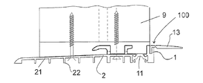
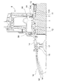
図1a〜1cには、本発明に基づく床敷居100の第1の実施形態が示されている。この場合、基板1は、少なくとも部分的に、内側Iを向く側面にある。図1aでは、この場合、底面Bの方向に屈曲できる内側脚部13が設けられている。このことは点線で描かれ、符号13cで示されている。基板1には、磁気シールストリップ5及び6を収容するための溝3及び4がある。磁気シールストリップ5及び6は、覆われている状態で、すなわちドアが閉められている場合、カウンタマグネット81によって引きつけられている。ここでは、ドアリーフに符号8が付けられ、一方、図1bでは、符号9のついた戸枠が示されている。第1の熱分離部11は、内側領域から外側領域方向へ基板1を熱的に分離している。基板1は、引き続き、外側へ向けられた終端エレメント2によって形成され、この終端エレメントは下部終端プレートを形成している。この下部終端エレメント2は、流出部71において外側Aに向かって延びる放水路7を境界している。外側の脚部14は、外側に向かって床敷居を終了し、一方、下部終端プレート又は下部終端エレメント2は、延長部21の中に延びている。延長部21は、ドア又は窓ドアの戸枠9がそこに固定できるように幅広に形成されている。このことを、図1bに示す。戸枠9は、詳しく図示されていない固定ネジによって床敷居100に固定される。このために、図1cに図示されているアダプタ90も用いられる。もちろん、この場合、図1bは、外側領域、すなわち戸枠9が見える領域のみを示している。延長部21又は下部終端エレメント2は支柱22を有しており、これらの支柱は、延長部21又は下部終端エレメント2を支持するために用いられ、詳細には、床敷居から底面Bへの熱伝導を防止するためにも用いられる。カウンタマグネット81は、担体84に固定されており、この担体は、固定手段85であるネジによってドアリーフ8に固定されている。
1a to 1c show a first embodiment of a
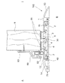
図2a〜2bには、本発明に基づく床敷居のもう1つの実施形態が示されている。ここでは、その他の全ての図と同様に、同一の符号は同一の特徴又はエレメントを示している。図1による解決方法とは違い、この場合、内側脚部13は図1aよりも短く形成されている。その他の点では、この実施形態は図1a〜図1cとほぼ同じである。従って、再度の符号の説明は省略する。
Figures 2a-2b show another embodiment of a floor sill according to the present invention. Here, like all other figures, the same reference signs indicate the same features or elements. In contrast to the solution according to FIG. 1, in this case the
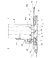
図3a及び3bには、本発明に基づく床敷居100のもう1つの実施形態が示されている。この実施形態は、内側を向く側面に終端の脚部が設けられていないという点でこれまでに示した実施形態とは異なっている。従って、バリアフリーの移行を保証するためには、内側の床の高さが、床敷居100の上部エッジ又は基板1の上部エッジで終了しなければならない。ここでも、その他のすべての符号は、図1及び2に示されている符号と同じ符号が使用されている。
Figures 3a and 3b show another embodiment of a
図4は、本発明に基づくもう1つの床敷居100を示し、この床敷居100は基板1から成る。基板1には、第1の熱分離部11と第2の熱分離部12とが、それぞれ磁気シールストリップ5、6用の溝3、4の横に配置されている。溝3、4は、基板1の下面を通る放水路7に接続されている。流出部71は、外側Aに向けられた基板1の側面に配置されている。底面Bを向く側面には、下部終端エレメント2が設けられている。この下部終端エレメント2は、第1及び第2の熱分離部11、12とまったく同様に、基板1とは異なる材料から形成されている。この場合、好ましくはプラスチックが使用される。言及したコンポーネントの十分な安定性を保証するため、繊維強化プラスチックを使用することも、当然可能である。しかし、本発明は、そのことに限定されていない。内側Iを向く基板1の側面には、内側脚部13が設けられている。外側Aを向く側面には、外側脚部14が配置されている。図に矢印で示されている床敷居100は、規定に即した仕様では、ドア8又は窓と連動する。図には、ドアリーフの側面図が示されている。ドアリーフの下面には、磁気ストリップ5、6に対応するカウンタマグネット81が配置されているため、ドア8が閉められている状態で、磁気ストリップ5、6は上方に引っ張られる。両方の溝3、4は、すでに言及したように、排水路7と接続されている。この排水路7は、適切に実施されている場合、排水路が終端エレメント2の上部を通り、問題なく外側Aに通じるように底面上をガイドされる。この場合、流出部71の流出開口部(詳しく図示されていない)は、内側の突起部30、40の方向にずれた状態で設けられている。この実施形態により、例えば強風又は横降りによって水分が内部へ押し込まれるのを防止することができる。しかし、外側Aへの流出は阻害されない。ドア8の外側Aを向く側面には、雨よけ板80が設けられている。この雨よけ板80は、この場合、中空形状として形成されている追加シール82を担持している。雨よけ板80は、ネジによってドアに固定されている。好ましくは、雨よけ板80の上部にさらにシールが設けられ、そこに水気が入り込むのを阻止するようになっている。このことは、例えば、通常のシリコン継ぎ目83であってもよく、この継ぎ目は雨よけ板を接続する前に取り付けられる。雨よけ板80は、2つの部品から形成されているため、例えばネジが見えないように取り付けることでき、後でネジが水分によって影響を受けることがなく、従って汚い錆つき箇所も生じない。
FIG. 4 shows another
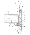
図5は、図4に示されている床敷居100のバリエーションである。この場合、図4と同じ符号が使用されている。符号は、有利には、その他の図においてもそのように使用されるため、必要な場合にのみ、もう一度違いが説明される。図4に示されている本発明のバリエーションとの違いでは、床敷居100に内側脚部13が装備されており、この内側脚部13と基板1との接続箇所には規定屈曲箇所130が設けられている。これにより、内側脚部13は位置13’に屈曲可能である。このことは、例えば内側の底面Bが外側の底面Bよりも低い場合に、b方向へ、すなわち底面Bの方に向かって行われる。この屈曲をさらに簡単にするため、規定屈曲箇所130に向かい合う面に凹部131が配置されている。この凹部は、図で分かるように、丸みがつけられているため、屈曲することによって、破損発生のおそれがあるような材料の変形は生じない。さらに、この凹部131によってb方向への屈曲が簡単になるのは当然である。
FIG. 5 is a variation of the
図6a、6b及び7は、図4及び5による床敷居のもう1つの実施形態を示しているが、ここでは、異なった、すなわち変更されたカウンタマグネット81が装備されている。図から明らかなように、この場合、カウンタマグネット81には、ピン842が形成されている。このピンは、ドア8又は窓のリーフ内にカウンタマグネット81を固定するために設けられている。そのためには、該当する穴を1つだけドア8の中に取り付ければよく、その穴の中にピン842を備えるカウンタマグネット81が押し込まれる。この場合、穴はピン842の外径よりも多少狭く実施されているので、ピン842が合い釘と同じように作用するという原理が働いている。そのために、ピン842は有利には溝又はネジ山を有しており、これによって、合い釘のような作用が得られる。図6bには、カウンタマグネット81の実施形態の拡大図が示されている。ここでは、このカウンタマグネット81が床敷居又は磁気ストリップ5、6の方を向く側面に平面Fを有していることが分かる。この平面Fは、好ましくは凹形に実施されている。さらに、このN極に磁化された平面Fには、好ましくは3極構造が備えられており、例えばS極、N極、S極の順番に並べられている。このことにより、磁気シールストリップは、ドアが閉められた状態で安全に引きつけられる。これにより、さらに、極めて有利な密閉作用が達成される。なぜなら、平面Fの凹形の実施形態により、風、水気及び/又は熱の通過が防止されるからである。図6aは、内側Iを向く脚部13に該当する規定屈曲箇所130が装備されているという点で図7とは異なっており、これによって、この脚部が、破線で示されている位置13’に動かされる。図7では、この脚部は固定されており、変更することはできない。
FIGS. 6 a, 6 b and 7 show another embodiment of the floor sill according to FIGS. 4 and 5, but here a different or modified
図8a、図8bおよび図9には、異なる長さの屈曲可能な内側脚部を備える、本発明に基づく床敷居100の次の実施形態のバリエーションが示されている。ここでも、前述のバリエーションですでに説明したように、同一の符号が使用されている。しかし、図から明らかなように、ここでは、前に説明されたバリエーションよりも(断面で見て)幅の寸法が大きい床敷居100が示されている。それ以外では、これまでと同様に、同一の符号が使用されている。これまで示されたバリエーションと異なるのは、ドア8の中に、担体84が埋め込まれている凹部が下面にあることである。この担体84は、例えば固定ネジなどによってドア8に固定することができる。この担体84はカウンタマグネット81を担持している。さらに、内側Iを向く側にはもう1つのシール85が設けられていることが分かり、これによって、全体として密閉作用をさらに高めている。外側脚部14又はこれと基板との接続部には、規定屈曲箇所140が設けられており、ここでも必要に応じて補正が行われる。その他のすべての符号はすでに説明され、これらの図でも同様に使用される。図8a、8b及び9は、内側Iを向く基板1の脚部13が異なる長さを有している点だけが異なっており、これによって、点線によって示された脚部13の位置13’で示されているように、さまざまな深さに脚部を屈曲することができる。この場合、例えば、内側を向く脚部13は、外側Aを向く脚部14よりも明らかに長く実施されている。これにより、脚部はかなり大きく曲がることができるため、例えば5〜10mm、とくに最大30mmのように、数ミリメートルのより大きな範囲で高さの違いを補正することができる。
FIGS. 8a, 8b and 9 show a variation of the following embodiment of a
図10aは、高さ調整形状Hとして接続形状15を備える床敷居100を示している。この接続形状15は、この場合、床敷居100の下面に固定されている。この固定は、例えば少なくとも1つのネジなど、一般的な固定手段で行われる。ここでは、接続形状15が追加脚部16を有しており、この追加脚部は、外側Aを向く側に設けられている。この追加脚部16も、16’で示されている位置までb方向へ曲がることができる。特定の寸法公差を補正できるようにするため、高さ調整装置17が設けられており、この装置は接続溝152の中に固定することができる。図で明らかなように、この高さ補正形状は、例えば該当するカウンタナットによって固定することができる。高さ補正形状Hは2つの部品から成り、すなわち、図10bに示されているように、接続形状15と追加脚部16とによって形成されている。ここでも、屈曲を簡単にするために、規定屈曲溝160と、この溝に対応する形で向かい合って形成されている成形部161とが設けられている。追加脚部16は、収容部151の中に、例えば曲げ部162を挿入することができる。これにより、取付けは、例えばまず、接続形状15を床敷居100に固定し、次に、床敷居100が同様に底面Bに固定されたら、追加脚部16を嵌め込むように実施することができる。そのような実施形態は、外側Aと内側Iとの間にあるより大きな高さの違いを克服しなければならない場合にとくに有利である。この場合、そのように実施された床敷居100及び接続形状15又は高さ補正形状Hは、ここでも、主に障害者用車両又は障害者用装置が乗り越えられる移行部を作るのを支援する。とくに古い建物では、そうした高さの違いが頻繁に見られるため、古い建物のリフォームでは、この種の床敷居が極めて有利に使用可能である。詰め物によって底面を補正することは、一般的に経費がかかり、詳細には該当するシーリングを使って行わなければならず、このことにより常に困難な問題が生じる。ここでは、高さ補正形状Hによって対処することができる。この高さ補正形状Hは、図示されているように床敷居100の外側Aを向く側面に配置でき、図示されていない実施形態では、内側Iを向く側面にも配置することができる。図10aには、さらに、この内側脚部13が位置13’まで屈曲可能に形成されていることも示されている。シール18は、複合金属シート19によって床敷居100又はその基板1の下面に固定されている。
FIG. 10 a shows a
図11a及び図11bには、高さ補正形状Hのもう1つのバリエーションが示されている。この形状は同様に接続形状15を特徴としているが、この接続形状は、断面で見ると円形に又はキャスタ受け具として形成されている収容部151を有し、これに対応する形で形成されている、追加脚部16又は中間部品163のキャスタ164を収容する。図11bでは、高さ補正形状Hが拡大され、別個に表示されている。この図でさらに明らかなように、中間部品163は差し込み溝165を有している。この溝は、端部が差し込み溝165に対応して形成されている追加脚部16を収容することができる。この追加脚部16は、さまざまな幅を克服するのに十分な幅をあらかじめ保持しておくことができる。従って、現場で調整を行うため、追加脚部16の一部を切断することが簡単にできる。このことは、例えば、相応に形成されているフライス又は鋸など、通常の加工ツールで行われる。中間部品163のローラ164は、収容部151の中に嵌め込まれている場合、中間部品163を望ましい位置に固定するため、終端部品153が、そのために設けられている固定溝154の中に嵌め込まれる。これにより、キャスタ受け具がいわば閉じられるため、中間部品163が外れることは不可能である。
11a and 11b show another variation of the height correction shape H. FIG. This shape is likewise characterized by a
図12には、床敷居100のもう1つの実施形態が示されている。ここでは、カウンタマグネット81が一体形成で形成されている。すなわち、カウンタマグネット81は、ドアが閉められた状態で、その幅にかけて磁気シールストリップ5、6のちょうど上にあり、両方のマグネットがそれぞれ引き合うように形成されている。この場合、カウンタマグネット81の極性は、個別のカウンタマグネットとちょうど同じように作用し、従って、ここでは、S極、N極、S極、及びS極、N極、S極の極性を設けることができるだろう。それ以外では、図12に示されている実施形態は、実質的に図6aに示されているバリエーションと同一である。
In FIG. 12, another embodiment of a
図13は、内側脚部13用の旋回装置200を備える、本発明に基づく床敷居のもう1つの実施形態を示している。図で明らかなように、この場合、旋回装置は、例えば接続形状15について図11a又は図11bに示されているように実施されている。従って、脚部は、床敷居1を向く側に管状の構造を有し、この構造は、床敷居1の内側端部で一種のボールジョイント内に嵌め込まれる。これにより、内側脚部13は、床敷居1の内側で、より低い場所にある床高さに問題なく配置することができる。図で明らかなように、熱分離部(ここでは図示されていない)も、前述した実施形態とは異なって実施されている。従って、本発明に基づく床敷居のこのバリエーションは、とくにこの特許出願の主要対象物の発展形態ともなり、独立請求項との関連でも、また従属請求項との関連でも、どちらでも組み合せることができる。ここでは、実施形態が、プラスチック製形状である窓形状又はドア形状によって示されている。この実施形態では、とくに内側を向くドアリーフ8の側面に追加のシール84がリップシールとして実施され、配置されているというもう1つの特徴にも注目しなければならない。これにより、システム全体の密閉性がさらに改善される。この実施形態により、底面領域がより深い場合でも、幾分高い場合でも、床敷居の内側で問題なく補正することができるため、取付け作業が行い易くなる。
FIG. 13 shows another embodiment of a floor sill according to the present invention comprising a
図14は、もう1つの接続アダプタ301を備える、本発明に基づく床敷居である。このもう1つの接続アダプタ301は接続形状15に配置されており、もう1つの接続アダプタ301は、クリップとして、接続アダプタ308に設けられている凹部の中にかみ合うことができる。この場合、もう1つの接続アダプタ301は、拡張部300を収容できるように形成されている。拡張部300の出口側端部には、底面を向く側にもう1つの高さ調整装置304が設けられている。拡張部300の外側縁部には、さらにもう1つのインターフェース303が配置されているため、そこにもう1つのアダプタを接続して、それに最終組み立てエレメント又は拡張部を取り付けることもできる。それ以外では、ここに示された実施形態は、符号に関してこれまでの図と同一と見なすことができ、すなわち同じ特徴には同じ符号が付けられている。
FIG. 14 is a floor sill according to the present invention comprising another
図15は、接続アダプタ308及びその前に位置する排水溝を備える、本発明に基づく床敷居を示し、接続部品307並びに終端側の出口部品309から成り、これらの2つのエレメントの間には格子306が設けられている。高さ調整装置17は、それぞれ排水溝の下に配置されている。床敷居の下には、外から内側への断熱をさらに改善する断熱層500が部屋側に設けられている。もちろん、ここでも、この図には詳しく示されていない外側の密閉層用のシールが設けられている。それ以外では、部屋側に追加のシール84を有するプラスチックエレメントも示されている。それ以外では、この実施形態においても、本発明のこれまでの実施形態と同様に、特徴が表示されている。
FIG. 15 shows a floor sill according to the invention with a
図16は、図14で説明されている接続アダプタ308、拡張部300、ならびに図15で説明されている排水溝を備える本発明に基づく床敷居を示している。ここでも、同一の符号が用いられている。図で明らかなように、アダプタ308と拡張部300の実施形態は、さらにその他のエレメントが、例えばインターフェース303などで拡張部300に配置できるように適切な形で利用される。このことは、同様に、クリップ接続で行われる。それに加えて接続形状が形成されており、ここではその接続形状が符号400で示されている。ここでは、もう1つのインターフェースが符号401で示されており、破線から分かるように、このインターフェースの中に接続形状402を回し入れてクリップ留めができるようになっている。出口側の底面には符号310が付けられている。その他のすべての符号は、すでにこれまでの図の中に示されている。
FIG. 16 shows a floor sill according to the present invention comprising the
図17は、本発明に基づくもう1つの実施形態を示しているが、図5及び図6aに示された本発明の実施形態とほぼ同じである。ここでの大きな違いは、熱分離部11及び12の実施形態が変更されていること、ならびに窓エレメント又はドアエレメントの形状の実施形態が変更されていることである。この場合も、プラスチック製形状の実施形態が示されており、この形態にも同様に、すでに説明したその他のすべてのエレメントが取り付けられている。そのため、再度の符号の説明は省略する。
FIG. 17 shows another embodiment according to the present invention, which is substantially the same as the embodiment of the present invention shown in FIGS. 5 and 6a. The major difference here is that the embodiment of the
図18は、図16ですでに説明した、本発明に基づく床敷居のバリエーションを示している。しかし、ここでは、床敷居1と、格子306及び外縁部309を備える排水溝との間に拡張部を配置せずに、排水溝が直接アダプタ308に固定されており、このアダプタが床敷居1に固定されている。
FIG. 18 shows a variation of the floor sill according to the invention already described in FIG. However, here, the drainage groove is directly fixed to the
図19は、図8bおよび図8cで説明された実施形態と同様と見なすことのできる、本発明に基づく床敷居を示している。しかし、この場合、窓エレメント又はドアエレメントとしてプラスチックエレメントが設けられている。内側縁部13は、この場合、明らかに底面の高さに適合することができる。
FIG. 19 illustrates a floor sill according to the present invention that can be considered similar to the embodiment described in FIGS. 8b and 8c. However, in this case, a plastic element is provided as a window element or a door element. The
図20及び21は、同様に、例えば図11a及び11bで示されたような接続形状を備える本発明による床敷居を示している。ここでは、この接続形状に符号15が付けられ、外側の追加脚部16が設けられており、この脚部は、図11a又は11bで示されたように、例えばキャスタ受け具として形成された収容部の中に配置されている。内側脚部13は、同様に、とくにこれまでの図ですでに説明したように屈曲可能に形成されている。図21と図20とは、内側脚部13が僅かに短く実施されている点が異なっている。それ以外では、ここでも、ドアエレメント又は窓エレメントとして、プラスチックエレメントが示されている。示されたすべての図において、窓エレメント又はドアエレメントとして、木材仕様又はプラスチック仕様が考えられているが、もちろんアルミニウムエレメントを用いることも可能であることは確実である。従って、本発明に基づく床敷居は、木材、プラスチック又はアルミニウム形状に汎用的に使用可能である。
FIGS. 20 and 21 likewise show a floor sill according to the invention with a connection shape, for example as shown in FIGS. 11a and 11b. Here, a
できる限り詳しく示されている正確な実施例を使って本発明を説明したが、これは説明のためにだけ用いられていること、また本発明が必ずしもこれだけに制限されないことを指摘しておく。なぜなら、本特許公開に関して、代替の実施例及び手順は当業者には明らかであるからである。従って、説明された本発明の内容から逸脱することなく実施可能な変更が考慮されるであろう。 Although the present invention has been described using precise embodiments, which are shown in as much detail as possible, it should be pointed out that this is used for illustration only and that the present invention is not necessarily limited thereto. This is because, with respect to this patent publication, alternative embodiments and procedures will be apparent to those skilled in the art. Accordingly, changes that may be made without departing from the scope of the invention described will be considered.
Claims (16)
Applications Claiming Priority (7)
| Application Number | Priority Date | Filing Date | Title |
|---|---|---|---|
| DE201220001082 DE202012001082U1 (en) | 2012-02-03 | 2012-02-03 | Barrier-free threshold, especially old building or renovation threshold |
| DE202012001082.4 | 2012-02-03 | ||
| US13/365,283 | 2012-02-03 | ||
| US13/365,283 US20130199101A1 (en) | 2012-02-03 | 2012-02-03 | Barrier-free floor threshold, in particular old building or renovation threshold |
| US13/531,222 | 2012-06-22 | ||
| US13/531,222 US20130199102A1 (en) | 2012-02-03 | 2012-06-22 | Barrier-free floor threshold, in particular old building or renovation threshold |
| PCT/EP2013/052105 WO2013113914A2 (en) | 2012-02-03 | 2013-02-01 | Barrier‑free floor sill, in particular old building or renovation sill |
Publications (1)
| Publication Number | Publication Date |
|---|---|
| JP2015510057A true JP2015510057A (en) | 2015-04-02 |
Family
ID=47749770
Family Applications (1)
| Application Number | Title | Priority Date | Filing Date |
|---|---|---|---|
| JP2014556016A Pending JP2015510057A (en) | 2012-02-03 | 2013-02-01 | Barrier-free floor sill, in particular for old buildings or renovations |
Country Status (3)
| Country | Link |
|---|---|
| EP (1) | EP2809864A2 (en) |
| JP (1) | JP2015510057A (en) |
| WO (1) | WO2013113914A2 (en) |
Cited By (1)
| Publication number | Priority date | Publication date | Assignee | Title |
|---|---|---|---|---|
| JP2019196267A (en) * | 2018-05-11 | 2019-11-14 | 三菱電機株式会社 | Position adjustment structure of landing sill |
Families Citing this family (6)
| Publication number | Priority date | Publication date | Assignee | Title |
|---|---|---|---|---|
| DE102015100266A1 (en) | 2015-01-09 | 2016-07-14 | Heroal - Johann Henkenjohann Gmbh & Co. Kg | Drainage system for door and window elements |
| CN104806135A (en) * | 2015-03-13 | 2015-07-29 | 肖正权 | Wooden door, window and line bottom waterproof technology |
| EP3396098B1 (en) * | 2017-04-24 | 2020-01-29 | SFS Group AG | Holder for weatherboarding and use of same |
| US11174673B2 (en) | 2019-05-24 | 2021-11-16 | Nana Wall Systems, Inc. | Threshold sill with removable barrier insert |
| EP4253709A1 (en) | 2022-03-31 | 2023-10-04 | ALUMAT Frey GmbH | Ground sill |
| DE102022115905A1 (en) | 2022-03-31 | 2023-10-05 | ALUMAT Frey GmbH | speed bump |
Citations (4)
| Publication number | Priority date | Publication date | Assignee | Title |
|---|---|---|---|---|
| JPH02112582A (en) * | 1988-08-05 | 1990-04-25 | Harry Frey | Magnet type sealing device for door |
| JP2007092340A (en) * | 2005-09-27 | 2007-04-12 | Matsushita Electric Works Ltd | Sliding door frame |
| DE102006007742A1 (en) * | 2006-01-13 | 2007-07-19 | Inge Frey | Ground sill for door element for sealing two spaces in ground area, particularly between outer and inner area of building, has tie body, which is attached on lower body introduced in building |
| DE202010011491U1 (en) * | 2009-11-30 | 2011-04-21 | Frey, Inge | speed bump |
Family Cites Families (5)
| Publication number | Priority date | Publication date | Assignee | Title |
|---|---|---|---|---|
| US2273877A (en) * | 1939-05-04 | 1942-02-24 | Fred W Kammerer | Door saddle |
| DE102005035220A1 (en) * | 2004-08-10 | 2006-06-01 | Inge Frey | Sliding element e.g. for windows, has lengthwise-running shifting movement with part of wall being able to open or lockable and in closed position gap opening is lockable by sealing element movable by magnetic forces |
| DE102005030462A1 (en) * | 2005-06-28 | 2007-01-04 | Inge Frey | Threshold for external door has applied seal held to outer wall of profile on outwardly-facing vertical face, by fastenings provided |
| DE102007003904B4 (en) * | 2007-01-19 | 2017-03-02 | Inge Frey | Threshold and sliding door with a threshold |
| DE202010004020U1 (en) * | 2010-03-22 | 2011-07-27 | Inge Frey | speed bump |
-
2013
- 2013-02-01 EP EP13705934.1A patent/EP2809864A2/en active Pending
- 2013-02-01 WO PCT/EP2013/052105 patent/WO2013113914A2/en active Application Filing
- 2013-02-01 JP JP2014556016A patent/JP2015510057A/en active Pending
Patent Citations (4)
| Publication number | Priority date | Publication date | Assignee | Title |
|---|---|---|---|---|
| JPH02112582A (en) * | 1988-08-05 | 1990-04-25 | Harry Frey | Magnet type sealing device for door |
| JP2007092340A (en) * | 2005-09-27 | 2007-04-12 | Matsushita Electric Works Ltd | Sliding door frame |
| DE102006007742A1 (en) * | 2006-01-13 | 2007-07-19 | Inge Frey | Ground sill for door element for sealing two spaces in ground area, particularly between outer and inner area of building, has tie body, which is attached on lower body introduced in building |
| DE202010011491U1 (en) * | 2009-11-30 | 2011-04-21 | Frey, Inge | speed bump |
Cited By (2)
| Publication number | Priority date | Publication date | Assignee | Title |
|---|---|---|---|---|
| JP2019196267A (en) * | 2018-05-11 | 2019-11-14 | 三菱電機株式会社 | Position adjustment structure of landing sill |
| JP6991099B2 (en) | 2018-05-11 | 2022-01-12 | 三菱電機株式会社 | Position adjustment structure of the landing threshold |
Also Published As
| Publication number | Publication date |
|---|---|
| EP2809864A2 (en) | 2014-12-10 |
| WO2013113914A2 (en) | 2013-08-08 |
| WO2013113914A3 (en) | 2013-10-24 |
Similar Documents
| Publication | Publication Date | Title |
|---|---|---|
| JP2015510057A (en) | Barrier-free floor sill, in particular for old buildings or renovations | |
| US20150013232A1 (en) | Barrier-free floor sill, in particular old building or renovation sill | |
| CA2158183A1 (en) | Magnetic door seal | |
| EP2362057A2 (en) | Drainage system for a sliding window or sliding door | |
| JP5500946B2 (en) | handrail | |
| EP2472029B1 (en) | A method for mounting a flashing for a roof window and a flashing system for a roof window | |
| JP4553885B2 (en) | Curtain wall structure of building | |
| KR101270572B1 (en) | Repairing windows | |
| KR101592152B1 (en) | Structure-reinforced and quickly-constructible balcony remodeling windows and doors and the method using the same | |
| KR101043068B1 (en) | Sliding window with heat and sound insulation structure | |
| KR20140106370A (en) | Windows and doors device that structure change is easy | |
| KR101631224B1 (en) | Finishing Member for Surface of Interior and Exterior Wall Support and Constructing Structure of Surface of Interior and Exterior Wall with Finishing Member | |
| KR101524973B1 (en) | A curtain wall for Aluminum-PVC integrated window. | |
| WO2007090394A1 (en) | Thermally resistive window sash member and window assembly | |
| KR101545152B1 (en) | Window frame structure for installation of window panel into frame | |
| KR20140105894A (en) | Windows and doors device that structure change is easy | |
| KR20100103273A (en) | Window frame having slidable outside window | |
| KR200394726Y1 (en) | A louver window system | |
| JP5425648B2 (en) | Retrofit sash | |
| KR102018425B1 (en) | Window fram dividing bar set being easy to install and adjust position and dividing window prepared therefrom | |
| JP5411007B2 (en) | Retrofit sash | |
| JP2009002078A (en) | Remodeling sash | |
| JP2783763B2 (en) | Renovated window frame structure | |
| KR20200095024A (en) | Middle bar drainage structure | |
| JP6697238B2 (en) | Lower frame and fittings |
Legal Events
| Date | Code | Title | Description |
|---|---|---|---|
| A621 | Written request for application examination |
Free format text: JAPANESE INTERMEDIATE CODE: A621 Effective date: 20151221 |
|
| A977 | Report on retrieval |
Free format text: JAPANESE INTERMEDIATE CODE: A971007 Effective date: 20161005 |
|
| A131 | Notification of reasons for refusal |
Free format text: JAPANESE INTERMEDIATE CODE: A131 Effective date: 20161011 |
|
| A601 | Written request for extension of time |
Free format text: JAPANESE INTERMEDIATE CODE: A601 Effective date: 20161214 |
|
| A601 | Written request for extension of time |
Free format text: JAPANESE INTERMEDIATE CODE: A601 Effective date: 20170224 |
|
| A02 | Decision of refusal |
Free format text: JAPANESE INTERMEDIATE CODE: A02 Effective date: 20170606 |