JP2015503700A - Method and system for managing clearance in a piston engine - Google Patents
Method and system for managing clearance in a piston engine Download PDFInfo
- Publication number
- JP2015503700A JP2015503700A JP2014550420A JP2014550420A JP2015503700A JP 2015503700 A JP2015503700 A JP 2015503700A JP 2014550420 A JP2014550420 A JP 2014550420A JP 2014550420 A JP2014550420 A JP 2014550420A JP 2015503700 A JP2015503700 A JP 2015503700A
- Authority
- JP
- Japan
- Prior art keywords
- assembly
- fluid
- piston
- cylinder
- bearing
- Prior art date
- Legal status (The legal status is an assumption and is not a legal conclusion. Google has not performed a legal analysis and makes no representation as to the accuracy of the status listed.)
- Pending
Links
Images


Classifications
-
- F—MECHANICAL ENGINEERING; LIGHTING; HEATING; WEAPONS; BLASTING
- F01—MACHINES OR ENGINES IN GENERAL; ENGINE PLANTS IN GENERAL; STEAM ENGINES
- F01B—MACHINES OR ENGINES, IN GENERAL OR OF POSITIVE-DISPLACEMENT TYPE, e.g. STEAM ENGINES
- F01B23/00—Adaptations of machines or engines for special use; Combinations of engines with devices driven thereby
- F01B23/10—Adaptations for driving, or combinations with, electric generators
-
- F—MECHANICAL ENGINEERING; LIGHTING; HEATING; WEAPONS; BLASTING
- F01—MACHINES OR ENGINES IN GENERAL; ENGINE PLANTS IN GENERAL; STEAM ENGINES
- F01B—MACHINES OR ENGINES, IN GENERAL OR OF POSITIVE-DISPLACEMENT TYPE, e.g. STEAM ENGINES
- F01B11/00—Reciprocating-piston machines or engines without rotary main shaft, e.g. of free-piston type
- F01B11/02—Equalising or cushioning devices
-
- F—MECHANICAL ENGINEERING; LIGHTING; HEATING; WEAPONS; BLASTING
- F16—ENGINEERING ELEMENTS AND UNITS; GENERAL MEASURES FOR PRODUCING AND MAINTAINING EFFECTIVE FUNCTIONING OF MACHINES OR INSTALLATIONS; THERMAL INSULATION IN GENERAL
- F16J—PISTONS; CYLINDERS; SEALINGS
- F16J1/00—Pistons; Trunk pistons; Plungers
- F16J1/08—Constructional features providing for lubrication
-
- F—MECHANICAL ENGINEERING; LIGHTING; HEATING; WEAPONS; BLASTING
- F16—ENGINEERING ELEMENTS AND UNITS; GENERAL MEASURES FOR PRODUCING AND MAINTAINING EFFECTIVE FUNCTIONING OF MACHINES OR INSTALLATIONS; THERMAL INSULATION IN GENERAL
- F16J—PISTONS; CYLINDERS; SEALINGS
- F16J10/00—Engine or like cylinders; Features of hollow, e.g. cylindrical, bodies in general
- F16J10/02—Cylinders designed to receive moving pistons or plungers
- F16J10/04—Running faces; Liners
-
- F—MECHANICAL ENGINEERING; LIGHTING; HEATING; WEAPONS; BLASTING
- F02—COMBUSTION ENGINES; HOT-GAS OR COMBUSTION-PRODUCT ENGINE PLANTS
- F02B—INTERNAL-COMBUSTION PISTON ENGINES; COMBUSTION ENGINES IN GENERAL
- F02B63/00—Adaptations of engines for driving pumps, hand-held tools or electric generators; Portable combinations of engines with engine-driven devices
- F02B63/04—Adaptations of engines for driving pumps, hand-held tools or electric generators; Portable combinations of engines with engine-driven devices for electric generators
- F02B63/041—Linear electric generators
-
- F—MECHANICAL ENGINEERING; LIGHTING; HEATING; WEAPONS; BLASTING
- F16—ENGINEERING ELEMENTS AND UNITS; GENERAL MEASURES FOR PRODUCING AND MAINTAINING EFFECTIVE FUNCTIONING OF MACHINES OR INSTALLATIONS; THERMAL INSULATION IN GENERAL
- F16C—SHAFTS; FLEXIBLE SHAFTS; ELEMENTS OR CRANKSHAFT MECHANISMS; ROTARY BODIES OTHER THAN GEARING ELEMENTS; BEARINGS
- F16C29/00—Bearings for parts moving only linearly
- F16C29/02—Sliding-contact bearings
- F16C29/025—Hydrostatic or aerostatic
Landscapes
- Engineering & Computer Science (AREA)
- General Engineering & Computer Science (AREA)
- Mechanical Engineering (AREA)
- Chemical & Material Sciences (AREA)
- Combustion & Propulsion (AREA)
- Pistons, Piston Rings, And Cylinders (AREA)
- Cylinder Crankcases Of Internal Combustion Engines (AREA)
- Magnetic Bearings And Hydrostatic Bearings (AREA)
- Reciprocating Pumps (AREA)
- Heat-Exchange Devices With Radiators And Conduit Assemblies (AREA)
Abstract
ピストン機関は、ピストンアセンブリとシリンダとの間に非接触軸受を含み得る。ピストンは、シリンダのボア内を平行移動するように構成され得、非接触軸受は、ピストンアセンブリとボアとの間の隙間内に含められ得る。軸受流体が、ピストンアセンブリおよび/またはシリンダを介して、隙間に供給され、非接触軸受を生成し得る。軸受要素は、隙間内の軸受流体の流動を方向付け、または別様に管理するために使用され得る。軸受要素は、1つ以上の孔、多孔性部分、および/または通路を含み、軸受流体を隙間に向け得る。The piston engine may include a non-contact bearing between the piston assembly and the cylinder. The piston can be configured to translate within the bore of the cylinder, and the non-contact bearing can be included in the gap between the piston assembly and the bore. Bearing fluid may be supplied to the gap via the piston assembly and / or cylinder to create a non-contact bearing. The bearing element may be used to direct or otherwise manage the flow of bearing fluid within the gap. The bearing element may include one or more holes, porous portions, and / or passages to direct bearing fluid to the gap.
Description
特定のボア対ストローク比率を維持しながら機関の圧縮比が増加するにつれて、上死点(TDC)における表面対容積比が増加し、温度が上昇し、圧力が増加する。これは、以下の3つの主要結果を有する。1)燃焼チャンバからの熱伝達が増加し、2)燃焼相調整が困難になり、3)摩擦および機械的損失が増加する。熱伝達は、TDCにおけるアスペクト比(すなわち、燃焼チャンバの長さに対するボア径の比率)がより小さくなるにつれて、熱境界層が、全体的容積のより大きな割合となるので増加する。燃焼相調整および完全燃焼の達成は両方とも、TDCにおいて実現される小容積のため、課題を呈する。燃焼チャンバ圧力の増加は、機関の構成可能に作用する力の増加に直接つながる。これらの大きな力は、機関(例えば、ピストンピン、ピストンロッド、クランクシャフト)内の機械的連結および圧力励起リングの両方に過負荷をかけ、したがって、摩擦、摩耗、および/または故障の増加を生じさせ得る。 As the engine compression ratio increases while maintaining a specific bore to stroke ratio, the surface to volume ratio at top dead center (TDC) increases, the temperature increases, and the pressure increases. This has three main consequences: 1) heat transfer from the combustion chamber increases, 2) combustion phase adjustment becomes difficult, and 3) friction and mechanical loss increase. Heat transfer increases as the aspect ratio at TDC (ie, the ratio of the bore diameter to the length of the combustion chamber) becomes smaller because the thermal boundary layer is a larger percentage of the overall volume. Combustion phase adjustment and achieving full combustion both present challenges due to the small volume realized in TDC. An increase in the combustion chamber pressure directly leads to an increase in the engineerably acting force. These large forces overload both mechanical connections and pressure excitation rings in the engine (eg, piston pins, piston rods, crankshafts), thus resulting in increased friction, wear, and / or failure. Can be.
線形ピストン機関に関連付けられた主要課題は、ピストンの運動エネルギーを機械的仕事および/または電気エネルギーに効率的に変換することである。本明細書では、「隙間」と称される、ピストンとシリンダ壁との間の空間は、ピストン整列を維持すること、ピストン壁接触および関連付けられた摩擦損失を防止すること、および、ピストンを越えたガス漏出(例えば、ブローバイ)を制御することにおいて重要である。隙間は、ピストンに作用する不均衡力、熱的に誘発された膨張または収縮(例えば、固体変形)、変化する機関条件、または他の関連要因によって影響を受け得る。隙間、ピストン温度、シリンダ温度、またはそれらの組み合わせの管理が、いくつかの用途において所望され得る。 A major challenge associated with linear piston engines is the efficient conversion of piston kinetic energy into mechanical work and / or electrical energy. The space between the piston and cylinder wall, referred to herein as a “gap”, maintains piston alignment, prevents piston wall contact and associated friction loss, and It is important in controlling the gas leakage (eg blow-by). The clearance may be affected by imbalance forces acting on the piston, thermally induced expansion or contraction (eg, solid deformation), changing engine conditions, or other related factors. Management of clearance, piston temperature, cylinder temperature, or a combination thereof may be desired in some applications.
いくつかの実施形態では、ピストン機関は、ピストンおよびシリンダアセンブリを含み得、シリンダのボアとピストンアセンブリとの間の隙間に流体軸受を含み得る。ピストンアセンブリは、ボア内を軸方向に平行移動可能であり得、ピストン面は、シリンダの燃焼区画に接触し、シリンダの一端に面し得る。少なくとも1つの軸受要素が、ボアとピストンアセンブリとの間の隙間に軸受流体の流動を提供し、流体軸受を形成し得る。いくつかの実施形態では、軸受要素は、ピストンアセンブリの一部であり、軸受流体の流動を半径方向外向きに提供し得、ピストンアセンブリは、流体通路を含み、軸受流体を向け得る。いくつかの実施形態では、軸受要素は、シリンダの一部であり、軸受流体の流動を半径方向内向きに提供し得、シリンダは、流体通路を含み、軸受流体を向け得る。軸受要素は、孔、噴散性表面、任意の他の好適な流体出口、または任意のそれらの組み合わせを含み、軸受流体を隙間に提供し得る。 In some embodiments, the piston engine may include a piston and cylinder assembly, and may include a fluid bearing in a gap between the cylinder bore and the piston assembly. The piston assembly may be axially translatable within the bore, and the piston face may contact the combustion section of the cylinder and face one end of the cylinder. At least one bearing element may provide a bearing fluid flow to a gap between the bore and the piston assembly to form a fluid bearing. In some embodiments, the bearing element is part of a piston assembly and may provide a flow of bearing fluid radially outward, the piston assembly including a fluid passage and directing the bearing fluid. In some embodiments, the bearing element may be part of a cylinder and provide a flow of bearing fluid radially inward, and the cylinder may include a fluid passage and direct the bearing fluid. The bearing element may include holes, squirting surfaces, any other suitable fluid outlet, or any combination thereof to provide bearing fluid to the gap.
いくつかの実施形態では、ピストン機関は、自己調心特徴を有するピストンとシリンダとを含むピストンシリンダアセンブリを含み得る。ピストンは、シリンダのボア内を軸方向に平行移動するように構成され得る。いくつかの実施形態では、ピストンは、シリンダのボア内を軸方向に平行移動する、ピストンアセンブリの一部であり得る。シリンダは、燃焼生成物を含むことが可能な燃焼区画を含み得る。燃焼区画からのブローバイガスは、燃焼区画から、ピストン面を越えて、ピストンとシリンダとの間の隙間を通して、軸方向に流動し得る。自己調心特徴は、ブローバイガスの流動を使用して、ピストンに自己調心力を提供し得る。自己調心特徴は、段、1つ以上のスロット付きポケット、テーパ状部分、任意の他の好適な特徴、または任意のそれらの組み合わせであり得る。 In some embodiments, the piston engine may include a piston cylinder assembly that includes a piston and a cylinder having self-aligning features. The piston may be configured to translate axially within the bore of the cylinder. In some embodiments, the piston may be part of a piston assembly that translates axially within the bore of the cylinder. The cylinder may include a combustion section that may contain combustion products. Blow-by gas from the combustion section can flow axially from the combustion section, beyond the piston face, through the gap between the piston and cylinder. The self-aligning feature may use blow-by gas flow to provide self-aligning force to the piston. The self-aligning feature can be a step, one or more slotted pockets, a tapered portion, any other suitable feature, or any combination thereof.
いくつかの実施形態では、ピストン機関は、1つ以上の熱パイプを有する、ピストンアセンブリを含み得る。ピストンアセンブリは、シリンダのボア内を軸方向に平行移動するように構成され得る。シリンダは、燃焼生成物を含むことが可能な燃焼区画を含み得、故に、ピストンアセンブリのピストン面は、温度上昇を被り得る。いくつかの実施形態では、熱パイプは、ピストン面と熱接触し得、ピストン面から熱容器に熱を伝達可能であり得る。熱パイプの第1の部分は、ピストン面から熱を受け取り得、熱パイプの第2の部分は、熱を熱容器に伝達し得る。熱パイプは、例えば、気相−液相転移を受け得る、水、エタノール、アンモニア、またはナトリウム等の流体を含み得る。 In some embodiments, the piston engine may include a piston assembly having one or more heat pipes. The piston assembly may be configured to translate axially within the bore of the cylinder. The cylinder may include a combustion section that may contain combustion products, and thus the piston face of the piston assembly may experience an increase in temperature. In some embodiments, the heat pipe may be in thermal contact with the piston surface and may be able to transfer heat from the piston surface to the heat vessel. The first portion of the heat pipe may receive heat from the piston face, and the second portion of the heat pipe may transfer heat to the heat vessel. The heat pipe can include a fluid such as water, ethanol, ammonia, or sodium that can undergo a gas phase-liquid phase transition, for example.
いくつかの実施形態では、ピストン機関は、ピストン機関のシリンダ内に同軸方向に位置付けられるように構成される、シリンダライナを含み得る。シリンダライナは、シリンダライナ内を軸方向に平行移動可能なピストンアセンブリと隙間を形成可能な内側面を含み得る。シリンダライナはまた、ピストン機関のシリンダと接触する、外側面を含み得る。外側面とシリンダとの間の界面は、圧力制御された流体のための導管として作用し得る、流体通路を含み得る。シリンダライナは、少なくとも部分的に、圧力制御された流体に基づいて、半径方向に収縮または膨張するように構成され得、したがって、隙間は、調節され得る。 In some embodiments, the piston engine may include a cylinder liner configured to be positioned coaxially within a cylinder of the piston engine. The cylinder liner may include an inner surface that can form a gap with a piston assembly that is axially translatable within the cylinder liner. The cylinder liner may also include an outer surface that contacts the cylinder of the piston engine. The interface between the outer surface and the cylinder can include a fluid passage that can act as a conduit for pressure-controlled fluid. The cylinder liner can be configured to contract or expand radially based, at least in part, on the pressure-controlled fluid, and thus the gap can be adjusted.
いくつかの実施形態では、ピストン機関は、局所的、選択的、即応的、あるいは別様に、制御された加熱または冷却をシリンダに提供するように構成される、1つ以上の流体通路を含み得る。流体通路に供給される流体の流量、温度、圧力、またはそれらの組み合わせは、制御システムによって調節され、ピストン機関の温度を制御し得る。いくつかの実施形態では、シリンダは、例えば、制御システムによって制御され、局所的加熱を提供し得る、1つ以上の電気加熱器等の1つ以上の局所的加熱源を含み得る。 In some embodiments, the piston engine includes one or more fluid passages configured to provide controlled heating or cooling to the cylinder locally, selectively, responsively, or otherwise. obtain. The flow rate, temperature, pressure, or combination thereof of fluid supplied to the fluid passage may be adjusted by the control system to control the temperature of the piston engine. In some embodiments, the cylinder may include one or more local heating sources, such as one or more electric heaters, which may be controlled by a control system and provide local heating, for example.
いくつかの実施形態では、同軸のピストンアセンブリとピストン機関のシリンダとの間の隙間は、制御され得る。例えば、隙間の温度、圧力、仕事相互作用、および/または他の好適なインジケータ等の少なくとも1つのインジケータが、1つ以上のセンサを使用して検出され得る。制御応答は、少なくとも部分的に、インジケータに基づいて、処理機器によって決定され得る。処理機器は、制御インターフェースを使用して、少なくとも部分的に、制御応答に基づいて、制御信号をピストン機関の少なくとも1つの補助システムに提供し得る。少なくとも1つの補助システムは、少なくとも部分的に、制御信号に基づいて、隙間を調節し得る。 In some embodiments, the clearance between the coaxial piston assembly and the cylinder of the piston engine can be controlled. For example, at least one indicator, such as gap temperature, pressure, work interaction, and / or other suitable indicator, may be detected using one or more sensors. The control response may be determined by the processing equipment based at least in part on the indicator. The processing equipment may use the control interface to provide a control signal to at least one auxiliary system of the piston engine based at least in part on the control response. The at least one auxiliary system may adjust the gap based at least in part on the control signal.
本開示の前述および他の特徴、その性質、ならびに種々の利点が、付随の図面と関連して検討される、以下の発明を実施するための形態の検討に応じて、より明白となるであろう。
本開示は、ピストン機関の隙間および/または他の特性を管理することを対象とする。自由ピストン機関の文脈において論じられるが、本明細書に開示される技法および配列は、非自由ピストン機関または他の好適な機械的システムに適用されることができる。本明細書では、用語「ピストン機関」は、自由および非自由両方のピストン機関を指すものとする。 The present disclosure is directed to managing piston engine clearances and / or other characteristics. Although discussed in the context of a free piston engine, the techniques and arrangements disclosed herein can be applied to non-free piston engines or other suitable mechanical systems. As used herein, the term “piston engine” is intended to refer to both free and non-free piston engines.
任意の好適な熱力学的サイクルを使用して動作する、ピストン機関は、ピストンおよびシリンダアセンブリを含み、変位仕事を実現させ得る。ピストンおよびシリンダは、比較的小隙間によって分離され得、ピストンは、シリンダのボア内を軸方向に平行移動する。いくつかの実施形態では、ピストンは、「ピストンアセンブリ」の一部として含まれ得、ピストンアセンブリは、少なくとも部分的にボア内において実質的剛体アセンブリとして連動して移動可能であり得る、1つ以上のピストンシール(例えば、ピストンリング)、軸受要素、フレーム、ピストンロッド、トランスレータ、および/または他の構成要素も含み得る。隙間は、ピストンアセンブリまたはその構成要素の半径方向周縁に沿って一定または可変であり得る(例えば、隙間は、厚さ値、値のプロファイルまたは場、および/または対称性メトリックによって説明され得る)。シリンダは、酸化性物質(例えば、空気、汚染空気、酸素)および燃料(例えば、ガス状または液体炭化水素燃料)が、燃焼のために、別個にまたは予混合された混合物として供給され得る燃焼区画を含み得る。高温燃焼生成物の膨張は、ピストンの変位を生じさせる。仕事は、機械的連結(例えば、ピストンロッドおよびクランクシャフトアセンブリを使用する)、電磁相互作用(例えば、本開示に説明されるようなトランスレータおよび固定子を有する、線形電磁機械(LEM)を使用する)、ガス連結(例えば、中間ガス容積を介して相互作用する2つのピストンを使用する)、任意の他の好適な仕事抽出技法、または任意のそれらの組み合わせを使用して、ピストンの運動から抽出され得る。ピストン−シリンダアセンブリによる空気および/または燃料の圧縮はまた、ピストンの運動を使用して達成され得る。いくつかの実施形態では、圧縮仕事は、ガス駆動、LEM、または両方によって提供され得る。 A piston engine operating using any suitable thermodynamic cycle can include a piston and cylinder assembly to achieve displacement work. The piston and cylinder can be separated by a relatively small gap, and the piston translates axially within the bore of the cylinder. In some embodiments, the piston may be included as part of a “piston assembly”, and the piston assembly may be movable in conjunction as a substantially rigid assembly at least partially within the bore. Piston seals (eg, piston rings), bearing elements, frames, piston rods, translators, and / or other components. The gap can be constant or variable along the radial periphery of the piston assembly or its components (eg, the gap can be described by a thickness value, a profile or field of values, and / or a symmetry metric). A cylinder is a combustion section in which oxidizing substances (eg air, polluted air, oxygen) and fuel (eg gaseous or liquid hydrocarbon fuel) can be supplied separately or as a premixed mixture for combustion. Can be included. Expansion of the hot combustion product causes piston displacement. Work uses a linear electromagnetic machine (LEM) with mechanical linkage (eg, using a piston rod and crankshaft assembly), electromagnetic interaction (eg, a translator and stator as described in this disclosure) ), Gas coupling (eg, using two pistons that interact through an intermediate gas volume), any other suitable work extraction technique, or any combination thereof, extracted from piston motion Can be done. Compression of air and / or fuel by the piston-cylinder assembly can also be achieved using piston motion. In some embodiments, the compression work may be provided by gas drive, LEM, or both.
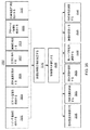
図1−4は、本開示の教示から利益を享受し得る、例証的ピストン機関を示す。本開示の教示は、図に図示され、本明細書に説明されるものに加え、任意の他の好適なピストン機関に適用され得ることを理解されるであろう。また、図1−4に図示されないが、ピストン機関は、例えば、冷却サブシステム、空気送達システム、燃料送達システム、点火サブシステム、排気システム、電子制御システム、および/または他の好適なサブシステム等の1つ以上のサブシステムを含み得、語句「ピストン機関」は、構成要素およびサブシステムの好適な集合を指し得ることを理解されるであろう。 1-4 illustrate an exemplary piston engine that may benefit from the teachings of the present disclosure. It will be appreciated that the teachings of the present disclosure may be applied to any other suitable piston engine in addition to those illustrated in the figures and described herein. Also, although not shown in FIGS. 1-4, the piston engine may be a cooling subsystem, air delivery system, fuel delivery system, ignition subsystem, exhaust system, electronic control system, and / or other suitable subsystem, etc. It will be understood that the phrase “piston engine” may refer to a suitable collection of components and subsystems.
図1は、本開示のいくつかの実施形態による、ピストンアセンブリ110、ガススプリング148、および統合型線形電磁機械(LEM)160を伴う、例証的ピストン機関100の断面図を示す。ピストン機関100は、ボア134および燃焼区画130を有するシリンダ140と、ピストンアセンブリ110とを含む。図示される実施形態では、ピストンアセンブリ110は、2つのピストン面112、ピストンシール114および115、およびトランスレータ116を含む。図1に図示されないが、ピストンアセンブリ110は、軸受要素、ピストンロッド、任意の他の好適な構成要素、または任意のそれらの組み合わせを含み得る。図示される実施形態では、ピストンアセンブリ110は、シリンダ140のボア134内に完全に位置し、かつ、実質的に、軸150に沿って、平行移動するように構成される。シリンダ140は、図1に示されるように、排気/注入ポート170(排気の除去および/または反応物の注入用)、吸入ポート180(空気および/または空気/燃料混合物の吸入用)、および駆動ガスポート190(駆動ガスの供給および/または除去用)を含む。ピストン機関100は、2ストロークサイクル、4ストロークサイクル、任意の他の好適なサイクル、または任意のそれらの組み合わせを使用して動作し得る。衝突板108が、いくつかの実施形態では、衝突抵抗、例えば、燃焼の間の衝突抵抗を支援するために含まれ得る。弁および/または他の流体構成要素が、ポート170、180、および190の一部または全部とともに使用され、流体のピストン機関100への流入およびそこからの流出を制御し得るが、必要ではない。
FIG. 1 illustrates a cross-sectional view of an
シリンダ140は、燃焼、ガス膨張、および排気が生じ得る、部分132と、電磁仕事相互作用が生じ得る、部分168と、ガス駆動およびガススプリングが生じ得る、部分178とを含み得る。部分132、168、および178は、シリンダ140の構成ならびにシリンダ140のボア134内のピストンアセンブリ110の位置に依存し得る。トランスレータ116の運動から電磁仕事を抽出するために使用される、固定子162が、図1に示されるように、シリンダ140の一部として含まれ得る。
燃焼区画130内の酸化性物質および燃料の燃焼による、シリンダ140内のピストンアセンブリ110の膨張ストロークの間、トランスレータ116は、固定子162を通して平行移動され得る。固定子162に対するトランスレータ116の運動は、電流および対応する電気仕事を発生させ得る。LEM160は、永久磁石機械、誘導機械、スイッチドリラクタンス機械、任意の他の好適な電磁機械、または任意のそれらの組み合わせを含み得る。例えば、トランスレータ116は、永久磁石を含み得、固定子162は、トランスレータ116の運動によって発生される誘導電流を伝導させ得る、ワイヤコイルを含み得る。
The
図2は、本開示のいくつかの実施形態による、ピストンアセンブリ210、ガススプリング248、およびLEM260を伴う、例証的ピストン機関200の断面図を示す。ピストン機関200は、ボア234を有するシリンダ240と、ピストンアセンブリ210と、燃焼区画230とを含む。図示される実施形態では、ピストンアセンブリ210は、ピストン面212と、ピストンシール214(例えば、ピストンリング、密閉表面)と、トランスレータ216と、ピストンロッド218とを含む。図2に図示されないが、ピストンアセンブリ210は、軸受要素、任意の他の好適な構成要素、または任意のそれらの組み合わせを含み得る。図示される実施形態では、ピストンアセンブリ210は、部分的に、シリンダ240のボア234内に位置し、実質的に軸250に沿って平行移動するように構成される。シリンダ240は、図2に示されるように、ガスシール242(相対的ピストン運動を可能にしながら、ガス漏出を低減または防止するため)と、排気/注入ポート270(排気の除去および/または反応物の注入用)と、吸入ポート280(空気および/または空気/燃料混合物の吸入用)と、駆動ガスポート290(駆動ガスの供給および/または除去用)とを含む。ピストン機関200は、2ストロークサイクル、4ストロークサイクル、任意の他の好適なサイクル、または任意のそれらの組み合わせを使用して動作し得る。衝突板208が、いくつかの実施形態では、含まれ得る。
FIG. 2 shows a cross-sectional view of an
シリンダ240は、燃焼、ガス膨張、および排気が生じ得る、部分232と、ガス駆動およびガススプリングが生じ得る、部分278とを含み得る。部分268は、シリンダ240と別個に含まれ得、電磁仕事相互作用が生じ得る、LEM260を含み得る。部分232、268、および278は、シリンダ240の構成ならびにシリンダ240のボア234内のピストンアセンブリ210の位置に依存し得る。トランスレータ216の運動から電磁仕事を抽出するために使用される、固定子262は、必要ではないが、図2に示されるように、シリンダ240と別個であり得る。
The
図3は、本開示のいくつかの実施形態による、2つのピストン311および313を有するピストンアセンブリ310と、別個のガススプリング348と、LEM360とを伴う、例証的ピストン機関300の断面図を示す。ピストン機関300は、それぞれ、ボア334および335を有するシリンダ340および341と、ピストンアセンブリ310と、燃焼区画330とを含む。図示される実施形態では、ピストンアセンブリ310は、ピストン面312と、トランスレータ316と、ピストンシール314および315と、ピストンロッド318とを含む。図3に図示されないが、ピストンアセンブリ310は、軸受要素、任意の他の好適な構成要素、または任意のそれらの組み合わせを含み得る。図示される実施形態では、ピストンアセンブリ310は、部分的に、シリンダ340のボア334内に、かつ部分的に、シリンダ341のボア335内に位置し、実質的に軸350に沿って平行移動するように構成される。シリンダ340は、図3に示されるように、ガスシール342(相対的ピストン運動を可能にしながら、ガス漏出を低減または防止するため)と、排気/注入ポート370(排気の除去および/または反応物の注入用)と、吸入ポート380(空気および/または空気/燃料混合物の吸入用)と、ガスポート395(ブローバイの除去または空気の供給用)とを含む。シリンダ341は、図3に示されるように、ガスシール343(相対的ピストン運動を可能にしながら、ガス漏出を低減または防止するため)と、駆動ガスポート390(駆動ガスの供給および/または除去用)とを含む。ピストン機関300は、2ストロークサイクル、4ストロークサイクル、任意の他の好適なサイクル、または任意のそれらの組み合わせを使用して動作し得る。衝突板308が、いくつかの実施形態では、含まれ得る。
FIG. 3 illustrates a cross-sectional view of an
シリンダ340は、燃焼、ガス膨張、および排気が生じ得る、部分332を含み得る。シリンダ341は、ガス駆動およびガススプリングが生じ得る、部分378を含み得る。部分368が、シリンダ340と341との間に含まれ得、電磁仕事相互作用が生じ得る、LEMを含み得る。部分332、368、および378は、シリンダ340および341の構成ならびにそれぞれのシリンダ340および341のボア334および335内のピストンアセンブリ310の位置に依存し得る。トランスレータ316の運動から電磁仕事を抽出するために使用される固定子362は、必要ではないが、図3に示されるように、シリンダ340および341から別個であり得る。
The
図4は、本開示のいくつかの実施形態による、2つのピストンアセンブリ410および411と、分離されたガススプリング448および449と、2つのLEM460および461を伴う、例証的ピストン機関400の断面図を示す。ピストン機関400は、示されるように、排気/注入ポート370を中心として対称であり、単一燃焼チャンバを有する2つのピストン機関300に実質的に均等である。他の2ピストン配列も、本開示に従って達成され得るが、対称である必要はなく、ピストン機関400は、例証的実施例であることを理解されるであろう。
FIG. 4 illustrates a cross-sectional view of an
ピストン機関100、200、300、および400等のピストン機関ならびにその動作および特性に関するさらなる詳細は、Simpson、他、米国特許出願第12/953,270号、Simpson、他、米国特許出願第12/953,277号、Simpson、他、米国特許出願第13/102,916号、およびRoelle、他、米国特許出願第13/028,053号に含まれ、全て、参照することによってその全体として本明細書に組み込まれる。
For further details regarding piston engines such as
(自己調心ピストン)
いくつかの実施形態では、ピストンは、ピストン機関のシリンダに対して自己調心を提供する、1つ以上の特徴を含み得る。
(Self-aligning piston)
In some embodiments, the piston may include one or more features that provide self-alignment to the cylinders of the piston engine.
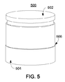
図5は、本開示のいくつかの実施形態による、自己調心特徴506を伴う、例証的ピストンアセンブリ500の一部の斜視図を示す。ピストンアセンブリ500は、ピストン面502、要素504、自己調心特徴506、任意の他の好適な構成要素(図示せず)、または任意のそれらの組み合わせを含み得る。いくつかの実施形態では、自己調心特徴506は、要素504の一部であり得る。例えば、要素504は、軸受要素(例えば、気体静力学的軸受)であり得、自己調心特徴506は、軸受要素内の機械加工された段または他の好適な特徴であり得る。いくつかの実施形態では、自己調心特徴506は、ピストン面502の一部であり得る。例えば、自己調心特徴506は、段、1つ以上のスロット付きポケット、テーパ状部分、またはピストンアセンブリ500内に含まれる他の特徴であり得る。いくつかの実施形態では、ピストンアセンブリは、ピストンアセンブリを調心することにおいて支援する1つ以上の特徴、構成要素、または両方を含み得る。例えば、ピストンアセンブリは、自己調心特徴と、ピストンを調心することにおいて支援し得るピストンアセンブリの1つ以上の側方表面にかかる圧力を等化することにおいて支援し得る特徴とを含み得る。図5に図示されないが、ピストンアセンブリ500は、随意に、ピストンロッド、トランスレータ、ピストンリング、流体軸受、任意の他の好適な構成要素、または任意のそれらの組み合わせを含み得る。
FIG. 5 illustrates a perspective view of a portion of an
図6は、本開示のいくつかの実施形態による、燃焼区画630からのブローバイ(矢印640によって示される)を伴う、ピストンアセンブリ610およびシリンダ620の例証的配列600の断面図を示す。いくつかの実施形態では、ピストン面602は、燃焼区画630(図6に図式的に示される)、ガス駆動区画(図6には図示せず)、ピストン機関シリンダ(図示せず)の任意の他の好適な区画、または任意のそれらの組み合わせに接触し得る。ブローバイは、燃焼区画630から、ピストン面602の周囲から、ピストンアセンブリ610に沿って軸方向に流動し得る。いくつかの実施形態では、ブローバイと自己調心特徴616との相互作用は、中心ピストンアセンブリ610を調心するように作用し得る。例えば、圧力分布が、ピストンアセンブリ610とシリンダ620との間の隙間に生成され、中心ピストンアセンブリ610を調心するように作用し得る。ブローバイは、燃焼区画、ガス駆動区画、または他の好適な区画から隙間に供給され、任意の好適な圧力で動作(例えば、圧力20〜800バールまたは他の好適な圧力で動作)し得る。
FIG. 6 illustrates a cross-sectional view of an exemplary arrangement 600 of
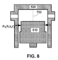
図7は、本開示のいくつかの実施形態による、例証的ピストンアセンブリ610およびシリンダ620の断面図を示し、ピストンアセンブリ610は、中心からずれている。シリンダ620の中心軸750は、シリンダ620のボアの幾何学的中心軸を図示する。ピストンアセンブリ610が、シリンダ620内において中心からずれると、図7に示されるように、ピストンアセンブリ610の側面に沿った(すなわち、θおよびZに伴って変動し得る、半径Rにおける)ピストンアセンブリに対する円筒座標内の圧力場P1(R,θ,Z)は、所与の軸方向位置Zにおいて円周方向に(すなわち、θ方向に)非均一となり得る。図8は、本開示のいくつかの実施形態による、例証的ピストンアセンブリ610およびシリンダ620の断面図を示し、ピストンアセンブリ610は、中心軸750を中心として中心に置かれている。ピストンアセンブリ610が、シリンダ620において中心に置かれると、図8に示されるように、ピストンアセンブリ610の圧力場P2(R,θ,Z)は、所与の軸方向位置Zにおいて、実質的に、円周方向に均一となり得る。いくつかの実施形態では、中心に置かれたピストンの圧力場は、非均一であり得るが、ピストンの側方表面にわたり積分すると、実質的にゼロ合力をもたらす。例えば、スロット付きポケットを有するピストンアセンブリは、ポケットにより、非均一円周方向圧力場を有し得るが、ゼロ合力をもたらし得る。
FIG. 7 shows a cross-sectional view of an
図9は、本開示のいくつかの実施形態による、ピストンアセンブリ910を調心することにおいて支援し得る特徴912を有する、ピストンアセンブリ910を伴う、例証的ピストン機関900の一部の断面図を示す。いくつかの実施形態では、特徴912等の特徴は、自己調心特徴(例えば、図10−12の自己調心特徴のいずれか)とともに、ピストンアセンブリ内に含まれ得る。特徴912は、図9に図示されるように、図9の隙間950内の圧力場を等化することにおいて支援し得る、ピストンアセンブリ910の全周の周囲に延在する1つ以上の溝を含み得る。特徴912はまた、隙間950内の軸方向流量を低減させるための直線状のラビリンスシールとして作用し得る。図9では、溝として、図式的に示されるが、任意の好適な特徴またはその特徴の組み合わせが、本開示に従って、調心することにおいて支援するために使用され得る。
FIG. 9 illustrates a cross-sectional view of a portion of an
図10は、本開示のいくつかの実施形態による、1つ以上のスロット1014を伴うポケット付き自己調心特徴1012を有する、ピストンアセンブリ1010を伴う、例証的ピストン機関1000の一部の断面図を示す。自己調心特徴1012は、各々が、ピストンアセンブリ1010の円周の周囲に部分的に延在する、1つ以上のポケットを含み得る。スロット1014は、ポケットに流入するブローバイのためのガイドとして作用し得る、1つ以上のスロット(例えば、1つ以上のポケットに対応する)を含み得る。ピストンアセンブリ1010の側方表面上に位置するように示されるが、いくつかの実施形態では、スロットは、ピストンアセンブリの内部に含まれ得、任意の好適な源から送給され得る。例えば、自己調心特徴1012は、各々が、円周上に120°離れて調心され、各々が、円周に沿って120°未満延在する、3つのスロット付きポケットと、流体が、比較的に高圧力領域1060からポケットに流入することを可能にし得る、3つの対応するスロット1014とを含み得る。任意の好適な数のポケットを含む、セグメント化されたポケットの任意の好適な配列が、本開示に従って使用され得る。
FIG. 10 illustrates a cross-sectional view of a portion of an
図11は、本開示のいくつかの実施形態による、段付き自己調心特徴1112を有する、ピストンアセンブリ1110を伴う、例証的ピストン機関1100の一部の断面図を示す。自己調心特徴1112は、ピストンアセンブリ1110の全周の周囲に延在する、段を含み得る。段は、任意の好適な絶対的および/または相対的寸法を含み得る。例証的実施例では、段における(すなわち、ピストン面1102に比較的に近い)隙間は、ピストンアセンブリのより大きな直径領域における隙間の約2倍であり得る。いくつかの実施形態では、ピストンアセンブリは、図10のスロット付きポケット配列と同様に、セグメント化された段を含み得るが、ポケットは、ピストン面1102まで通って延在し、故に、スロットは、含まれる必要はない。
FIG. 11 illustrates a cross-sectional view of a portion of an
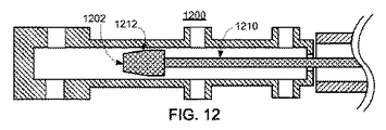
図12は、本開示のいくつかの実施形態による、テーパ状自己調心特徴1212を有する、ピストンアセンブリ1210を伴う、例証的ピストン機関1200の一部の断面図を示す。自己調心特徴1212は、ピストンアセンブリ1210の全周の周囲に延在する、テーパ状部分を含み得、ピストン面1202における直径は、比較的に収縮される。テーパは、任意の好適な絶対的および/または相対的寸法を含み得る。例証的実施例では、テーパの小径における(すなわち、ピストン面1202に比較的に近い)隙間は、ピストンアセンブリのより大きな直径領域における隙間の約2倍であり得る。いくつかの実施形態では、ピストンアセンブリは、図10のスロット付きポケット配列と同様に、円周の周囲に2つ以上のテーパ状区画を含み得、テーパは、ピストン面1202まで通って延在する。
FIG. 12 illustrates a cross-sectional view of a portion of an
いくつかの実施形態では、自己調心特徴1012、1112、および1212、特徴912、ならびに他の好適な自己調心特徴または他の特徴の一部あるいは全部は、組み合わせられ得る。例えば、ピストンアセンブリは、テーパ、ステップ、および一連の溝(例えば、ラビリンス)を含み、調心を提供し得る。自己調心特徴は、燃焼区画、ガス駆動区画、ガススプリング区画、ブローバイガスがピストン面を越えて流動することを可能にする任意の他の好適なピストン面、または任意のそれらの組み合わせと接触する、ピストン面の近傍で使用され得る。例えば、図3のピストン機関300を参照すると、自己調心特徴は、ピストン面312のいずれかの近傍に含まれ得る。
In some embodiments, self-aligning
(非接触軸受)
いくつかの実施形態では、非接触軸受が、ピストンと対応するシリンダとの間で使用され得る。非接触軸受は、例えば、気体静力学的軸受、流体静力学的軸受、または、移動または静止し得る他の好適な非接触軸受を含み得る。非接触軸受は、ピストンおよびシリンダ壁を分離する、流体の薄膜を含み、摩擦および関連付けられる仕事損失を低減させ得る。いくつかの実施形態では、気体静力学的軸受の使用は、ピストン機関のピストンおよびシリンダアセンブリの無給油動作を可能にし得、故に、ピストン機関は、補助給油システムを要求する必要がなく、これは、機関構造のいくつかの側面を簡略化し得る。いくつかの実施形態では、非接触軸受は、軸受流体として、油を含み得る。軸受流体は、例えば、空気、窒素、排気、油、液体水、水蒸気、液体CO2、ガス状CO2、油圧流体、任意の他の好適な流体、または任意のそれらの組み合わせを含み得る。流体軸受において使用される流体は、ピストンアセンブリ、シリンダ、または両方を通して供給され得る。
(Non-contact bearing)
In some embodiments, non-contact bearings can be used between the piston and the corresponding cylinder. Non-contact bearings can include, for example, gas static bearings, hydrostatic bearings, or other suitable non-contact bearings that can move or be stationary. Non-contact bearings may include a thin film of fluid that separates the piston and cylinder walls, reducing friction and associated work loss. In some embodiments, the use of gas hydrostatic bearings may allow oilless operation of the piston and cylinder assembly of the piston engine, and therefore the piston engine need not require an auxiliary oiling system, which Some aspects of the engine structure can be simplified. In some embodiments, the non-contact bearing may include oil as the bearing fluid. The bearing fluid may include, for example, air, nitrogen, exhaust, oil, liquid water, water vapor, liquid CO 2 , gaseous CO 2 , hydraulic fluid, any other suitable fluid, or any combination thereof. The fluid used in the hydrodynamic bearing can be supplied through a piston assembly, a cylinder, or both.
図13は、本開示のいくつかの実施形態による、孔1312を有する、軸受要素1310を伴う、例証的ピストンアセンブリ1300の一部の斜視図を示す。孔1312は、パターンで配列されるか、ランダムに配列されるか、または任意のそれらの組み合わせであり得る。孔1312は、任意の好適な寸法を有し得る。例えば、いくつかの実施形態では、孔1312は、千分の数インチ以下から1/8インチ以上の範囲であり得る。いくつかの実施形態では、孔1310の寸法は、1つ以上の他の流量制限または有効面積に対する孔の相対的流量制限または有効面積に基づいて選択され得る。例えば、孔は、孔1310の下流の軸受流体の排気経路の流量制限と同じくらいの流量制限を提供するようにサイズ決定され得る。ピストンアセンブリ1300が、ピストン面1302またはピストンアセンブリ1300の他の好適なピストン面(図示せず)にかかる力によって、好適なシリンダのボア内を平行移動する場合、軸受要素は、調心を維持することにおいて支援し得る。流体は、矢印1322によって示されるように、任意の好適な流体源から供給され得、孔1312への内部流体通路(図示せず)を介して、ピストンアセンブリ1300内に分配され得る。孔1312から流出後、流体は、隙間を通って、ピストンアセンブリ1300の少なくとも一部に沿って流動し得る。軸受要素1310からの流体の外向流は、矢印1320によって示されるように、ピストンアセンブリ−シリンダ接触を防止および/または低減することにおいて支援し得る。
FIG. 13 illustrates a perspective view of a portion of an
図13では、孔として示されるが、任意の好適なポートが、流体を隙間に提供し、流体軸受としての役割を果たすために使用され得る。例えば、嵌合部品間の間隙は、流体を隙間に提供するために使用され得る。さらなる実施例では、ピストンアセンブリの円周の周囲に部分的または完全に延在するリングの形状におけるオリフィスが、流体を隙間に提供するために使用され得る。いくつかの実施形態では、軸受要素1310は、噴散をもたらすために十分に小さい(例えば、軸受流体の平均自由経路より小さい)ポートを含み得る。
Although shown in FIG. 13 as a hole, any suitable port can be used to provide fluid to the gap and serve as a fluid bearing. For example, a gap between mating parts can be used to provide fluid to the gap. In a further embodiment, an orifice in the form of a ring that extends partially or fully around the circumference of the piston assembly can be used to provide fluid to the gap. In some embodiments, the
図14は、本開示のいくつかの実施形態による、多孔性軸受要素1410を伴う、例証的ピストンアセンブリ1400の一部の斜視図を示す。ピストンアセンブリ1400が、ピストン面1402またはピストンアセンブリ1400の他の好適なピストン面(図示せず)にかかる力によって、好適なシリンダのボア内を平行移動する場合、軸受要素は、調心を維持することにおいて支援し得る。流体は、矢印1422によって示されるように、任意の好適な流体源から供給され得、内部流体通路(図示せず)を介して、ピストンアセンブリ1400内に分配され得、次いで、軸受要素1410の任意の好適な部分の空隙空間を通して流動し得る。軸受要素1410は、任意の好適な多孔率および細孔サイズを有し得る。軸受要素1410の側方表面から流出後、ガスは、隙間を通して、ピストンアセンブリ1400の少なくとも一部に沿って、流動し得る。軸受からの流体の外向流は、矢印1420に示されるように、要素1410は、ピストンアセンブリ−シリンダ接触を防止および/または低減することにおいて支援し得る。軸受要素1410は、流体が流動することを可能にし得る多孔率を有する、任意の好適な材料から構築され得る。例えば、多孔性軸受要素は、黒鉛、焼結された金属(例えば、鉄、鋼鉄、青銅)、焼結または別様の多孔性セラミック(例えば、炭化ケイ素、アルミナ、マグネシア)、焼結または別様の任意の他の好適な材料、あるいは任意のそれらの組み合わせから構築され得る。いくつかの実施形態では、軸受要素1410は、噴散を可能にするために十分に小さい(例えば、軸受流体の平均自由経路より小さい)細孔サイズを有し得る。
FIG. 14 shows a perspective view of a portion of an
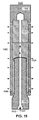
図15は、本開示のいくつかの実施形態による、例証的ピストンアセンブリ1500の断面図を示し、流体軸受1510は、ピストンアセンブリ1500を通して送給される。ピストンアセンブリ1500は、ピストン1502、軸受要素1510、フレーム1550、締結具1590、図15に示されない任意の他の好適な構成要素、または任意のそれらの組み合わせを含み得る。ピストンアセンブリ1500は、ピストン機関のシリンダのボアに嵌め入るように構成され得、実質的にボアの中心線上またはその近傍の軸に沿って、平行移動するように構成され得る。軸受要素1510は、矢印1522によって示されるように、1つ以上の入口ポート1512から、1つ以上のポートまたは表面に軸受流体を分配し、矢印1520によって示されるように、半径方向外向きに流動させ得る、流体通路1560を含む。いくつかの実施形態では、軸受要素1510は、複数の構成要素のアセンブリを含み得る。いくつかの実施形態では、ピストン1502は、随意に、自己調心特徴または他の好適な特徴(図示せず)を含み得る。
FIG. 15 illustrates a cross-sectional view of an exemplary piston assembly 1500 according to some embodiments of the present disclosure, where the
図16は、本開示のいくつかの実施形態による、例証的ピストンアセンブリ1610およびシリンダ1620の断面図を示し、流体軸受1612(例えば、少なくとも部分的に軸受要素1618から生じる隙間内に位置する流体層)は、ピストンアセンブリ1610を通して送給される。ピストンアセンブリ1610は、軸受流体1616を受け取り得る、内部通路1614を含む。軸受要素1618は、そこから軸受流体が流体軸受1612に流入し得る孔または多孔性部分を含むピストンアセンブリ1610の一部である。軸受要素1618は、ピストンの一体部分(図16に示されるように)、ピストンアセンブリ1610の別の部分、ピストンアセンブリ1610に嵌合される別個の構成要素(例えば、締まり嵌めまたは締結具を用いて搭載することによって)である任意の他の好適な配列を有するか、または任意のそれらの組み合わせであり得る。流体軸受1612は、シリンダ1620のボアの中心を表す軸1650を中心としたピストンアセンブリ1610を調心することにおいて支援し得る。
FIG. 16 illustrates a cross-sectional view of an
図17は、本開示のいくつかの実施形態による、例証的ピストンアセンブリ1710およびシリンダ1720の断面図を示し、流体軸受1712は、シリンダ1720を通して送給される。シリンダ1720は、軸受流体1716を受け取り得る、内部通路1714を含む。軸受要素1718は、そこから流体が、ピストンアセンブリ1710とシリンダ1720との間の好適な隙間内の流体軸受1712に流入し得る、孔または噴散性表面を含むシリンダ1720の一部である。軸受要素1718は、シリンダ1720の一体部分(図17に示されるように)、シリンダ1720に嵌合される別個の構成要素(例えば、インサートまたはライナ等)である任意の他の好適な配列を有するか、または任意のそれらの組み合わせであり得る。流体軸受1712は、シリンダ1720のボアの中心を表す、軸1750を中心としたピストンアセンブリ1710を調心することにおいて支援し得る。いくつかの実施形態では、シリンダは、軸受流体を1つ以上の対応する流体軸受に提供し得る1つ以上の軸受要素を含み得る。例えば、いくつかの実施形態では、シリンダのボアは、各々が、軸受流体をシリンダのボア内の複数の場所に送給し得る、別個かつ制御可能な流体源を伴う、複数の軸受要素を含み得る。
FIG. 17 illustrates a cross-sectional view of an
いくつかの実施形態では、ブ軸受要素に隣接する隙間の一部内へのブローバイガスの流動を低減または防止するために、ローバイガスが経路指定され得る。例えば、ブローバイガスは、ブローバイガスの流動が、実質的に、隙間内の軸受流体の流動を改変しないように、シリンダ、ピストンアセンブリ、または両方を通して経路指定され得る。例えば、ブローバイガス等の他の流動による軸受ガス流のいくつかの変化は、ピストン−シリンダ接触を防止する軸受流体の能力に悪影響を及ぼし得る。ブローバイガスの経路指定は、例えば、軸受流体排気圧が、流体送給圧力を比較的に大きく下回ることを可能(例えば、軸受流体のより大きな圧力降下を可能)にし得、これは、所望の流動および軸受特性を提供し得る。 In some embodiments, low-by gas may be routed to reduce or prevent flow of blow-by gas into a portion of the gap adjacent to the bearing element. For example, blow-by gas may be routed through a cylinder, piston assembly, or both such that the flow of blow-by gas does not substantially alter the flow of bearing fluid in the gap. For example, some changes in bearing gas flow due to other flows, such as blow-by gas, can adversely affect the ability of the bearing fluid to prevent piston-cylinder contact. Blow-by gas routing may, for example, allow the bearing fluid exhaust pressure to be relatively well below the fluid delivery pressure (eg, allow for a greater pressure drop of the bearing fluid), which may be desired flow rate. And may provide bearing properties.
図18は、本開示のいくつかの実施形態による、軸受要素1812および1813と、流体通路1875を有するトランスレータ1814とを伴う、ピストンアセンブリ1810およびシリンダ1820の例証的配列1800の断面図を示す。ピストン面1802は、配列1800のガススプリング(例えば、ガス駆動区画)に接触し得る一方、ピストン面1804は、配列1800の燃焼区画に接触し得る。配列1800は、トランスレータ1814と電磁的に相互作用し得る、固定子1815を含み得る。
FIG. 18 shows a cross-sectional view of an
図示される実施形態では、軸受流体1874は、導管1872がシール1871を介して接続される、導管1870に供給される。シール1871は、図18に図示されるように、導管1872を含む、ピストンアセンブリ1810が、導管1870と1872との間に圧力シールを維持しながら、軸1850を中心として平行移動することを可能にし得る。導管1872の内部は、トランスレータ1814内に位置する、流体通路1875に結合され、そこから軸受流体1874が、通路1816に流入し得る。通路1816は、軸受流体1874を軸受要素1812および1813に送給し、そこから、軸受流体1874は、ピストンアセンブリ1810とシリンダ1820との間の隙間内の流体軸受に流入する。いくつかの実施形態では(図示せず)、導管1870、導管1872、または両方は、可撓性であり、相対的運動を可能にし得る。例えば、いくつかの実施形態では(図示せず)、導管1870は、好適なホース継手を介して、直接、トランスレータ1814に接続される、可撓性ホースであり得る(例えば、故に、導管1872は、含まれる必要がない)。
In the illustrated embodiment, bearing fluid 1874 is supplied to
図19は、本開示のいくつかの実施形態による、軸受要素1912および1913と、弁1970とを伴う、ピストンアセンブリ1910およびシリンダ1920の例証的配列1900の断面図を示す。ピストン面1902は、配列1900のガススプリング(例えば、ガス駆動区画)に接触し得る一方、ピストン面1904は、配列1900の燃焼区画に接触し得る。配列1900は、トランスレータ1914と電磁的に相互作用し得る固定子1915を含み得る。
FIG. 19 illustrates a cross-sectional view of an
図示される実施形態では、ガススプリング1976の流体の少なくとも一部は、ピストン面1902に位置する弁1970を介して、軸受流体として、通路1916に供給される(例えば、矢印1974によって示されるように)。弁1970は、能動または受動弁、あるいは1つ以上の方向に流体流動の制御を提供する、他の好適なポート付きデバイスを含み得る。例えば、弁1970は、リード弁、ボール弁、ニードル弁、ボール逆止弁、ダイヤフラム逆止弁、異なる流動方向のために異なる抵抗を提供する導管内の静的流量制限、任意の他の好適な弁、電子コントローラまたは他の能動的位置調整システム、任意の他の好適なデバイス、あるいは任意のそれらの組み合わせを含み得る。通路1916は、軸受流体1974を軸受要素1912および1913に送給し、そこから、軸受流体は、ピストンアセンブリ1910とシリンダ1920との間の隙間内の流体軸受に流入する。いくつかの実施形態では、弁1970は、逆止弁であり得る。故に、ピストンアセンブリ1910が、軸1950に沿って平行移動するにつれて、かつ流体がガススプリング1976からポート1990(例えば、1つ以上の弁を含み得る)を介して、供給および/または除去されるにつれて、ガススプリング1976内の圧力は、クラッキング圧に到達し得、流体は、弁1970を通して通路1916に流入し得る。弁1970のクラッキング圧は、任意の好適な値であり得、いくつかの実施形態では、能動的に調節可能であり得る。いくつかの実施形態では、弁1970は、能動的に制御可能であり得、いずれかの方向における流動は、弁1970のオリフィスまたは他の流量制限を制御することによって制御され得る。
In the illustrated embodiment, at least a portion of the fluid in the gas spring 1976 is supplied to the
いくつかの実施形態では、軸受要素は、ピストンの一体部分であり得る。例えば、ピストンは、軸受流体を隙間に提供する、機械加工された通路および孔の集合を有し得る。いくつかのそのような実施形態では、ピストンは、必要ではないが、ピストンアセンブリの一部であり得る。軸受要素は、黒鉛要素、機械加工された特徴を伴う金属要素、焼結された金属要素、多孔性セラミック要素、非多孔性セラミック要素、好適な材料の任意の他の好適な要素、または任意のそれらの組み合わせを含み得る。 In some embodiments, the bearing element can be an integral part of the piston. For example, the piston may have a collection of machined passages and holes that provide bearing fluid to the gap. In some such embodiments, the piston is not necessary, but can be part of the piston assembly. The bearing element can be a graphite element, a metal element with machined features, a sintered metal element, a porous ceramic element, a non-porous ceramic element, any other suitable element of a suitable material, or any A combination thereof may be included.
(シリンダおよび/またはピストンの温度管理)
いくつかの実施形態では、ピストン(または、そのアセンブリ)、シリンダ、または両方の温度は、制御または別様に管理され得る。ピストン(または、そのアセンブリ)および/またはシリンダの温度管理は、ピストン機関の1つ以上の構成要素の熱変形を管理することによって、隙間を維持または別様に管理することにおいて支援し得る。
(Cylinder and / or piston temperature control)
In some embodiments, the temperature of the piston (or assembly thereof), cylinder, or both can be controlled or otherwise managed. Piston (or assembly thereof) and / or cylinder temperature management may assist in maintaining or otherwise managing the clearance by managing thermal deformation of one or more components of the piston engine.
いくつかの実施形態では、1つ以上の熱パイプが、ピストンアセンブリの熱伝達に影響を及ぼすために使用され得る。熱パイプは、例えば、ピストン機関の構成可能へおよびそこからの熱伝達を支援するように構成される、流体導管を含み得る。ピストンアセンブリのピストン面は、燃焼により、温度上昇を被り得る。熱パイプの使用は、ピストン面、ピストンアセンブリの任意の他の好適な部分、または任意の他の好適な構成要素から熱を取り除き、構成要素の動作温度を低下させることにおいて支援し得る。例えば、熱パイプは、ピストン面から、軸受要素、隙間、シリンダのボアの表面、冷却剤によって冷却されるピストンロッド、任意の他の好適な熱容器、または任意のそれらの組み合わせ等の熱容器に熱を伝達し得る。 In some embodiments, one or more heat pipes may be used to affect the heat transfer of the piston assembly. The heat pipe may include, for example, a fluid conduit that is configured to assist heat transfer to and from the configurable piston engine. The piston face of the piston assembly can undergo a temperature rise due to combustion. The use of a heat pipe may assist in removing heat from the piston face, any other suitable part of the piston assembly, or any other suitable component and reducing the operating temperature of the component. For example, the heat pipe from the piston surface to a heat vessel such as a bearing element, gap, cylinder bore surface, piston rod cooled by a coolant, any other suitable heat vessel, or any combination thereof. Can transfer heat.
熱パイプは、例えば、水、エタノール、アンモニア、ナトリウム、あるいは任意の他の好適な流体または混合物等、好適な流体で充填され得る、流体導管を含み得る。流体の相転移に関連付けられた潜熱は、概して、温度差による感知可能エネルギーの伝達をはるかに上回る。加えて、流体の相転移は、実質的に一定または別様に制限された温度で生じ得(圧力および任意の存在する不純物に依存し得る)、これは、ピストン機関内の比較的に大きな温度勾配を低減させることにおいて支援し得る。熱パイプは、ピストンアセンブリのピストン面と熱接触する、ピストンアセンブリの一部として配列され得る。いくつかの実施形態では、熱パイプを有するピストンアセンブリの線形運動は、熱パイプ内で流体を輸送することにおいて支援し、したがって、ピストン面からピストン機関の比較的に冷たい部分への熱伝達を支援し得る。 The heat pipe may include a fluid conduit that may be filled with a suitable fluid, such as, for example, water, ethanol, ammonia, sodium, or any other suitable fluid or mixture. The latent heat associated with fluid phase transitions generally far exceeds the transfer of sensible energy due to temperature differences. In addition, fluid phase transitions can occur at substantially constant or otherwise limited temperatures (which can depend on pressure and any impurities present), which is a relatively high temperature in the piston engine. May assist in reducing the slope. The heat pipe may be arranged as part of the piston assembly that is in thermal contact with the piston face of the piston assembly. In some embodiments, the linear motion of the piston assembly with the heat pipe assists in transporting fluid within the heat pipe and thus assists in heat transfer from the piston face to the relatively cooler part of the piston engine. Can do.
構成要素間の語句「熱接触」は、構成要素間の動作上の熱伝達の能力を指すことを理解されるであろう。例えば、熱パイプは、ピストン面と接触して配列され得、かつピストン面から熱を伝達し得、したがって、ピストン面と「直接」熱接触し得る。さらなる実施例では、熱パイプは、ピストン面と接触し得る、ピストンフレームと接触し得、熱パイプは、ピストン面から熱を伝達し得る、ピストンフレームから熱を伝達し得、したがって、熱パイプは、ピストン面と「間接的に」熱接触し得る。 It will be understood that the phrase “thermal contact” between components refers to the capability of operational heat transfer between the components. For example, the heat pipe can be arranged in contact with the piston face and can transfer heat from the piston face and thus can be in “direct” thermal contact with the piston face. In a further embodiment, the heat pipe may contact the piston frame, which may contact the piston face, the heat pipe may transfer heat from the piston frame, which may transfer heat from the piston face, and thus the heat pipe is , May be in “indirect” thermal contact with the piston face.
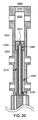
図20は、本開示のいくつかの実施形態による、ピストンアセンブリの一部として含まれる、熱パイプ2080を伴う、ピストン機関2000の例証的ピストンアセンブリ2010およびシリンダ2020の断面図を示す。パイプまたは他の流体導管であり得る、熱パイプ2080は、ピストン機関2000の動作の間、気相−液相転移を受け得る、流体2082を含み得る。熱伝達(矢印2024によって示される)は、機関動作の間、燃焼区画2030からピストン面2002に生じ得る。熱伝達(矢印2024によって示される)はさらに、ピストン面2020から熱パイプ2080の部分2084に生じ得、これは、ピストン面2020の温度を低減、維持、または両方を行なうことにおいて支援し得る。熱パイプ2080内の熱伝達は、熱パイプ2080の部分2084から熱パイプ2080の部分2086に生じ得る。部分2086は、ピストン面2002から離れたピストンアセンブリ2010の部分、例えば、燃焼区画2030の遠位および部分2086に比較的近いシリンダ2020の端部等に熱を伝達し得る。例えば、熱パイプ2080は、燃焼区画2030から、半径方向外向きに、軸受面、隙間、次いで、シリンダに熱2024を伝達することにおいて支援し得、そこで、例えば、冷却剤通路内の冷却剤を介して、さらに伝達され得る。さらなる実施例では、熱パイプ2080は、燃焼区画2024からシリンダ2020のガス駆動区画2040に熱を伝達することにおいて支援し得る。
FIG. 20 shows a cross-sectional view of an
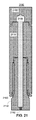
図21は、本開示のいくつかの実施形態による、内部空隙によって形成される熱パイプ2180を伴う、例証的ピストンアセンブリ2100の断面図を示す。ピストンアセンブリ2100は、ピストン2102、要素2110、フレーム2150、締結具2190、図21に示されない任意の他の好適な構成要素、または任意のそれらの組み合わせを含み得る。ピストンアセンブリ2100は、ピストン機関のシリンダのボアに嵌合するように構成され得、実質的に、ボアの中心線上またはその近傍の軸に沿って、平行移動するように構成され得る。要素2110は、(図示されないが)軸受要素(例えば、軸受通路を伴う)、ピストンリング、フレーム、任意の他の好適な構成要素、任意の他の好適な特徴、または任意のそれらの組み合わせを含み得る。熱パイプ2180内の流体は、弁(例えば、逆止弁、または遮断弁)、プラグ、または他の構成要素を含み得る、ポート2182を使用して、充填、通気、または別様に調節され得る。いくつかの実施形態では、ポート2182を伴う、熱パイプ2180は、ピストン機関の動作の間、充填、通気、または別様に調節可能であり得る。いくつかの実施形態では、ポート2182を伴う、熱パイプ2180は、ピストン機関の動作の間、充填、通気、または別様に調節可能である必要はなく、故に、ピストン機関が動作していない間、調節され得る。
FIG. 21 illustrates a cross-sectional view of an exemplary piston assembly 2100 with a
いくつかの実施形態では、複数の熱パイプが、ピストンアセンブリの周縁近傍の直径上に含まれ、ピストン面から隙間および内側シリンダ壁に熱を伝達することにおいて支援し得る。例証的実施例では、6〜12の熱パイプが、ピストンアセンブリの周縁近傍の直径上に軸方向に配列されて配向され得るが、任意の好適な数の熱パイプが、そのような環状配列において使用され得る。いくつかの実施形態では、環状熱パイプが、ピストンアセンブリ内に含まれ、隙間に熱を伝達することにおいて支援し得る。例えば、ピストンアセンブリ内の環状空隙は、動作の間、好適な流体で充填され、密閉され得る。 In some embodiments, a plurality of heat pipes may be included on the diameter near the periphery of the piston assembly to assist in transferring heat from the piston face to the gap and the inner cylinder wall. In an illustrative embodiment, 6-12 heat pipes may be oriented axially arranged on the diameter near the periphery of the piston assembly, but any suitable number of heat pipes may be in such an annular arrangement. Can be used. In some embodiments, an annular heat pipe may be included in the piston assembly to assist in transferring heat to the gap. For example, the annular void in the piston assembly can be filled and sealed with a suitable fluid during operation.
図22は、本開示のいくつかの実施形態による、ピストンアセンブリ2210と、冷却剤通路2222および2238ならびに熱パイプ2224を有する、シリンダ2220とを有する、例証的ピストン機関2200の断面図を示す。いくつかの実施形態では、ピストン機関2200は、冷却剤通路2222を含み、ピストン機関2200の1つ以上の構成要素の温度を制御または別様に制限することにおいて支援し得る。温度制御はまた、シリンダボアのサイズおよび/または形状を制御するために使用され得(例えば、熱変形を制御することによって)、これは、ブローバイ特性および/または軸受性能を改善または別様に調節し得る。図22に図式的に示されるように、シリンダ2220は、それぞれ、矢印2230および2234と、矢印2232および2236とによって示されるように、冷却剤流体を供給および返流させ得る、1つ以上のポートによって送給される、内部通路を含み得る。示されるように、冷却剤通路2222および冷却剤通路2238は、環状空隙を含むが、任意の好適な配列が、本開示に従って使用され得る。いくつかの実施形態では、エチレングリコール、プロピレングリコール、水、アルコール、空気、任意の他の好適な流体、または任意のそれらの組み合わせ(例えば、水で希釈されたエチレングリコール)等の冷却剤が、冷却剤通路2222および2238に供給され得る。いくつかの実施形態では(図示せず)、ピストン機関2200は、ポンプ、ラジエータ、温度調整器、圧力調整器、流体取扱導管、任意の他の好適な構成要素、または任意のそれらの組み合わせを含み得る、冷却剤サブシステムを含み得る。いくつかの実施形態では、冷却剤通路2222および冷却剤通路2238は、シリンダ2220内で相互接続され得、故に、単一セットの通路として制御され得る。いくつかの実施形態では、冷却剤通路2222および冷却剤通路2238は、シリンダ2220内で相互接続される必要はなく、別個に制御可能であり得る。例えば、いくつかの実施形態では、冷却剤通路2222および冷却剤通路は、選択的に、シリンダ2220の異なるゾーンを冷却することにおいて支援し得、故に、各ゾーンは、別個に冷却され得る。例証的実施例では、制御システムは、ピストンアセンブリ2210とシリンダ2220との間の隙間が、ピストンが、燃焼区画2270内にあるとき、大き過ぎることを決定し得る。故に、冷却剤通路2238より比較的にTDCに近い、冷却剤通路2222に供給される冷却剤の流量は、増加され、シリンダを冷却し、ボアを縮小させ(熱収縮を介して)、ひいては、隙間を縮小させ得る。任意の好適な数の別個の冷却剤通路が、本開示に従って、任意の好適な構成に配列される、選択的冷却を提供するために使用され得る。いくつかの実施形態では、シリンダ2220は、1つ以上の熱パイプ2224を含み、ピストン機関2200の1つ以上の構成要素の温度を制御または別様に制限することにおいて支援し得る。1つ以上の熱パイプ2224は、シリンダ2220内に任意の好適な配列で含まれ得、任意の好適な熱パイプ流体を含み得る。例えば、1つ以上の熱パイプ2224は、シリンダ2220のボアの中心に中心を置かれた直径上に、軸方向に配列された複数の熱パイプを含み得る。さらなる実施例では、1つ以上の熱パイプ2224は、シリンダ2220内に環状空隙を含み得る。熱パイプポート2226が、いくつかの実施形態では、使用され、1つ以上の熱パイプ2224内の流体を供給、除去、または別様に制御し得る。例えば、熱パイプポート2226は、弁、調整器、オリフィス、任意の他の好適な特徴またはデバイス、あるいは任意のそれらの組み合わせを含み、1つ以上の熱パイプ2224またはその中に含まれる流体の特性を制御し得る。いくつかの実施形態では、冷却剤通路2222および/または冷却剤通路2238は、直接、1つ以上の熱パイプ2224に接触(図示せず)し得、1つ以上の熱パイプ2224からの比較的に増加した熱伝達を提供し得る。冷却剤通路2222および2238ならびに1つ以上の熱パイプ2224が、図22に示されるが、いくつかの実施形態(図22には図示せず)は、冷却剤通路および1つ以上の熱パイプのいずれかを含み得、故に、両方を含む必要はない。冷却剤通路2222および2238ならびに1つ以上の熱パイプ2224を一緒に使用することは、いくつかの配列では、いずれかの単独の使用と比較して、比較的に向上した熱伝達を提供し得る。例えば、熱は、シリンダ2220のボアから、隙間を介して、1つ以上の熱パイプ2224に伝達され得、1つ以上の熱パイプ2224は、この熱の少なくとも一部を冷却剤通路2222および/または冷却剤通路2238内の冷却剤に伝達し得る(例えば、熱伝達は、シリンダ2220の一部を通した伝導を含み得る)。
FIG. 22 illustrates a cross-sectional view of an
いくつかの実施形態では、ポート2250のいずれかに供給される流体は、ピストンアセンブリ2210またはその一部を冷却するために使用され得る。例えば、ピストンアセンブリ2210のピストン面からの熱は、ピストンアセンブリ2210のピストンロッドに輸送され得、ポート2250のいずれかに供給される流体は、ピストンアセンブリ2210のピストンロッドを対流によって冷却し得る。
In some embodiments, fluid supplied to any of the
いくつかの実施形態では、流体軸受は、ピストンアセンブリ、シリンダ、その構成要素、ピストン機関の任意の他の好適な構成要素、または任意のそれらの組み合わせの冷却を支援し得る。軸受流体は、軸受流体をピストン−シリンダアセンブリの好適な隙間に向け得る、軸受要素に供給され得る。軸受流体は、隙間を通して流動するにつれて、ピストン−シリンダアセンブリの少なくとも一部を冷却することにおいて支援し得る。いくつかの実施形態では、軸受流体は、燃焼区画から実質的に離れて隙間を通して流動し得、故に、熱を燃焼区画から運び出し、したがって、ピストン機関の1つ以上の構成要素の温度を低下させ得る。いくつかの実施形態では、ピストン機関の隙間を通る軸受流体の対流は、ピストン面とピストンアセンブリおよび/またはシリンダの別の部分との間の有効熱伝達率を増加させ得る。いくつかの実施形態では、1つ以上の熱パイプが、軸受要素を有するピストンアセンブリ内に含まれ得る。1つ以上の熱パイプは、軸受要素またはその軸受要素の一部をほぼ等温に維持することにおいて支援し得、これは、熱膨張および隙間の関連付けられた変化の制御を支援し得る。いくつかの実施形態では、1つ以上の熱パイプ、冷却剤通路、軸受要素、任意の他の好適な構成要素、または任意のそれらの組み合わせの使用は、ピストン機関の1つ以上の構成要素の熱変形を管理することによって、隙間を維持または別様に管理することにおいて支援し得る。 In some embodiments, the hydrodynamic bearing may assist in cooling the piston assembly, cylinder, its components, any other suitable component of the piston engine, or any combination thereof. The bearing fluid can be supplied to a bearing element that can direct the bearing fluid to a suitable gap in the piston-cylinder assembly. As the bearing fluid flows through the gap, it may assist in cooling at least a portion of the piston-cylinder assembly. In some embodiments, the bearing fluid may flow through the gap substantially away from the combustion compartment, thus carrying heat away from the combustion compartment and thus reducing the temperature of one or more components of the piston engine. obtain. In some embodiments, convection of the bearing fluid through the piston engine gap may increase the effective heat transfer rate between the piston face and the piston assembly and / or another portion of the cylinder. In some embodiments, one or more heat pipes can be included in a piston assembly having bearing elements. The one or more heat pipes may assist in maintaining the bearing element or a portion of the bearing element approximately isothermal, which may assist in controlling thermal expansion and associated changes in clearance. In some embodiments, the use of one or more heat pipes, coolant passages, bearing elements, any other suitable component, or any combination thereof may be used for one or more components of the piston engine. By managing thermal deformation, it may help in maintaining or otherwise managing the gap.
(シリンダライナ)
いくつかの実施形態では、自由ピストンとシリンダとの間の隙間は、制御または別様に管理され得る。いくつかの実施形態では、変形可能シリンダライナが、ピストンアセンブリが移動するボアを調節することによって、隙間を調節するために使用され得る。いくつかの実施形態では、ライナ流体が、シリンダライナの面間の圧力差に基づいて変形し得る変形可能シリンダライナに圧力を印加するために使用され得る。ライナ流体は、例えば、水、エチレングリコール、プロピレングリコール、油、油圧流体、燃料(例えば、ディーゼル燃料)、任意の他の好適な流体、または任意の好適なそれらの組み合わせを含み得る。
(Cylinder liner)
In some embodiments, the clearance between the free piston and the cylinder can be controlled or otherwise managed. In some embodiments, a deformable cylinder liner can be used to adjust the clearance by adjusting the bore through which the piston assembly moves. In some embodiments, liner fluid can be used to apply pressure to a deformable cylinder liner that can deform based on a pressure difference between the faces of the cylinder liner. The liner fluid may comprise, for example, water, ethylene glycol, propylene glycol, oil, hydraulic fluid, fuel (eg, diesel fuel), any other suitable fluid, or any suitable combination thereof.
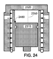
図23は、本開示のいくつかの実施形態による、変形可能シリンダライナ2330を伴う、例証的ピストンアセンブリ2310およびシリンダ2320の断面図を示す。変形可能シリンダライナ2330の内部表面は、ボアを画定し得、その中で、ピストンアセンブリ2310またはその一部が、ボアの中心において、軸2350に沿って平行移動し得る。通路2322が、シリンダ2320と変形可能シリンダライナ2330との間に形成され得、その中に、ライナ流体が、ポート2324を介して、供給および/または返流され得る。好適な圧力に制御されたライナ流体は、変形力を変形可能シリンダライナ2330に付与し、ボアが、適宜調節されることを可能にし得る。ボアとピストンアセンブリ2310との間の隙間2360は、故に、好適な圧力におけるライナ流体の印加によって調節され得る。ライナ流体の圧力を増加させることは(例えば、ポート2324のうちの1つ以上を介して、ライナ流体を通路2322に供給することによって)、ボアおよび隙間2360を縮小させ得る一方、ライナ流体の圧力を減少させることは(例えば、ポート2324のうちの1つ以上を介して、ライナ流体を通路2322から除去することによって)は、ボアおよび隙間2360を拡大させ得る。図24は、本開示のいくつかの実施形態による、変形を受けている変形可能シリンダライナ2330を伴う、図23の例証的ピストンアセンブリ2310およびシリンダ2320の断面図を示す。ライナ流体圧力は、図24に示されるように、図23に示されるものに対して、通路2322内においてより大きくなり、故に、隙間2460は、隙間2360より比較的に小さい。
FIG. 23 illustrates a cross-sectional view of an
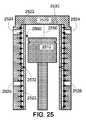
図25は、本開示のいくつかの実施形態による、区画化された変形可能シリンダライナ2530を伴う、例証的ピストンアセンブリ2510およびシリンダ2520の断面図を示す。変形可能シリンダライナ2530の内部表面は、ボアを画定し得、その中で、ピストンアセンブリ2510またはその一部が、ボアの中心において、軸2550に沿って平行移動し得る。通路2522および2523が、シリンダ2520と変形可能シリンダライナ2530との間に形成され得、シール2532によって分離され得る。ライナ流体は、それぞれ、ポート2524およびポート2525を介して、通路2522および2523に供給され、および/またはそこから返流され得、必要ではないが、互から隔離され得る。好適な圧力に制御されたライナ流体は、変形力を変形可能シリンダライナ2530に付与し、各区画におけるボア(すなわち、通路2522または2523に対応するボアの部分)が、適宜調節されることを可能にし得る。いくつかの実施形態では、ライナ流体の圧力は、変形可能シリンダライナ2530の変形が、ライナ流体とボアとの間の差圧に依存し得るので、少なくとも部分的に、ボアの好適な区画内の圧力に基づいて制御され得る。ボアとピストンアセンブリ2510との間の隙間2560は、故に、好適な圧力におけるライナ流体の印加によって調節され得る。隙間は、通路2522および2523の各々に対応する隙間が、独立して調節され得るので、軸方向(すなわち、軸2550と平行)に変動し得る。例えば、いくつかの実施形態では、ピストン2512が、変形可能シリンダライナ2530の区画を通して進行するにつれて、隙間は、その区画で調節され得る。ライナ流体の圧力を増加させることは(例えば、それぞれのポート2524および/または2525のうちの1つ以上を介して、ライナ流体を通路2522および/または2523に供給することによって)は、1つ以上の場所において、ボアおよび隙間2560を縮小させ得る一方、ライナ流体の圧力を減少させることは(例えば、それぞれのポート2524および/または2525のうちの1つ以上を介して、ライナ流体を通路2522および/または2523から除去することによって)は、1つ以上の場所において、ボアおよび隙間2560を拡大させ得る。
FIG. 25 illustrates a cross-sectional view of an
図26は、本開示のいくつかの実施形態による、変形可能シリンダライナ2630を伴う、例証的ピストン機関2600の断面図を示す。通路2622が、シリンダ2620と変形可能シリンダライナ2630との間に形成され得、その中に、ライナ流体は、ポート2624を介して、供給および/または返流され得る。好適な圧力に制御されたライナ流体は、変形力を変形可能シリンダライナ2630に付与し、ボアが、適宜調節されることを可能にし得る。図示される実施形態では、ポート2626(例えば、燃料および/または空気を提供する、または排気を受け取り得る)は、変形可能シリンダライナ2630の外側に位置し、変形可能シリンダライナ2630内のポートまたは他の開口部の必要性を排除し得る。ピストンアセンブリ2610と変形可能シリンダライナ2630との間の隙間の調節は、通路2622内のライナ流体の圧力の調節によって達成され得る。
FIG. 26 illustrates a cross-sectional view of an
いくつかの実施形態では、ライナ流体の流動は、変形可能シリンダライナのための冷却を提供するために使用され得る。例えば、圧力制御および流量制御されたライナ流体は、対流熱伝達を変形可能シリンダライナ(例えば、燃焼区画の近傍)からライナ流体に提供するために使用され得る。ライナ流体を用いた冷却は、冷却剤通路および/または熱パイプの使用を用いた冷却(例えば、図22に示されるように)と連動して、あるいはその代わりに、使用され得る。 In some embodiments, the flow of liner fluid can be used to provide cooling for the deformable cylinder liner. For example, pressure-controlled and flow-controlled liner fluid can be used to provide convective heat transfer from a deformable cylinder liner (eg, near the combustion compartment) to the liner fluid. Cooling with the liner fluid can be used in conjunction with or instead of cooling with the use of coolant passages and / or heat pipes (eg, as shown in FIG. 22).
図27は、本開示のいくつかの実施形態による、局所的冷却剤通路2752および2754を伴う、例証的ピストン機関2700の一部の断面図(ボア軸に垂直)を示す。ピストン機関2700のシリンダ2720は、1つ以上のスロットル2724および1つ以上のスロットル2726に結合され得る、1つ以上のプレナム2722を含み得る。いくつかの実施形態では、絞り調節された流体が、1つ以上のプレナム2722から、1つ以上のスロットル2724を通して、領域2732を冷却するように構成される、冷却剤通路2752内に流動し得る(例えば、冷却剤通路2752内の例証的矢印によって示されるように)。いくつかの実施形態では、絞り調節された流体は、1つ以上のプレナム2722から、1つ以上のスロットル2726を通して、領域2734を冷却するように構成される、冷却剤通路2754内に流動し得る(例えば、冷却剤通路2754内の例証的矢印によって示されるように)。1つ以上のスロットル2724および2726は、各々が、固定流量制限オリフィス、調節可能流量制限オリフィス、制御可能絞り弁、任意の他の好適な流体絞り特徴、または任意のそれらの組み合わせを含み得る。1つ以上のスロットル2724および2726は、絞り調節された流体の圧力の減少を生じさせ得、また、絞り調節された流体の温度および/またはエンタルピーの低下ももたらし得る。流体温度および/またはエンタルピーの低下は、シリンダ2720のボア(例えば、ピストンアセンブリ2710を格納するように構成される、図示されるボア)からの熱伝達を向上させ得る。いくつかの実施形態では、冷却剤通路2752および2754は、管状導管、マニホールド、または他の流動指向構成要素を含み、絞り調節された流体の流動を1つ以上のスロットル2724および2726からシリンダ2720の局所的空間領域に提供し、次いで、流体を流体制御システム(例えば、戻りラインおよびリザーバを含み得る)に返流し得る。ピストン機関2700は、必要ではないが、相互接続され得る任意の好適な数のプレナム2722を含み得る。例えば、プレナム2722は、各々が、選択可能冷却をシリンダ2720の局所的空間領域に提供するために別個に制御可能である複数のプレナムを含み得る。さらなる実施例では、プレナム2722は、複数のスロットルに結合され、選択可能冷却をシリンダ2720の局所的空間領域に提供し得る単一プレナムを含み得る。複数のスロットルは、シリンダ2720の1つ以上の局所的空間領域の冷却を制御するために、別個に制御可能であるか、または別様に固有の流量制限特性を有し得る。いくつかの実施形態では、絞り調節された流体を使用するシリンダ2720の冷却は、シリンダ温度およびシリンダ2720とピストンアセンブリ2710との間の隙間の制御を可能にし得る。いくつかの実施形態では、ボア幾何学形状(例えば、サイズ、形状、または両方)の直接または間接的測定が、制御システムによって、局所的冷却剤通路2752および2754による冷却を制御するために使用され得る。例えば、より高い動作温度が、TDCの近傍の燃焼区画2730の近くにおいて予期され得、増加した冷却が、領域2732に提供され、温度場を制限し得る。さらなる実施例では、いくつかの状況では、減少した冷却が、領域2732に提供され、対応するボアおよび関連付けられた隙間を拡大させ得る。冷却の増加または減少は、スロットルの絞り作用を増加または減少させることによって、絞り調節された流体の温度を調節することによって、絞り調節された流体の流量を調節することによって、任意の他の好適な調節によって、または任意のそれらの組み合わせによって提供され得る。絞り調節された流体は、液体またはガスであり得る、任意の好適な冷却剤流体を含み得る。例えば、絞り調節された流体は、エチレングリコール、プロピレングリコール、水、アルコール、空気、任意の他の好適な流体、または任意のそれらの組み合わせ(例えば、水で希釈されたエチレングリコール)を含み得る。シリンダ2720は、流体(例えば、空気、燃料、排気、またはそれらの組み合わせ)をピストン機関2700の好適な区画に供給するために、またはそこから除去するための任意の好適なポート2770を含み得る。
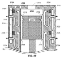
FIG. 27 shows a cross-sectional view (perpendicular to the bore axis) of a portion of an
図28は、本開示のいくつかの実施形態による、局所的冷却剤通路2826を伴う、例証的ピストン機関2800の一部の断面図(ボア軸と平行)を示す。ピストン機関2800は、プレナム2822を有するシリンダ2820を含み得る。シリンダ2820は、ベクトル2850および2860のベクトルの外積と実質的に平行な方向に、実質的に線形に移動するように構成される、ピストンアセンブリ2810を格納するように構成される、ボアを含み得る。図28では、環状プレナムとして示されるが、プレナム2822は、任意の好適な流路を提供するように配列される、任意の好適な導管形状を含み得る。冷却剤は、スロットル2824を通して、局所的冷却剤通路2826に流入し、シリンダ2820の対応する空間領域を冷却し得る。図示される実施形態では、冷却剤は、スロットル2824から半径方向内向きに流動し(図28の半径方向内向きを指す4つの矢印によって示されるように)、次いで、ベクトル2850とベクトル2860のベクトルの外積(図28の平面方向における2850×2860)によって与えられる方向に流動する。冷却剤の戻り流路は、図28に示されないが、半径方向、軸方向、または両方の流路を含み得る。いくつかの実施形態では、スロットル2824は、局所的流体通路2826内に流体噴流を生成し得、流体噴流は、シリンダ2820の空間領域に衝突し、比較的に増加した対流熱伝達をその領域にもたらし得る。図28では、4つの対称の局所的冷却剤通路2826を有するとして示されるが、ピストン機関2800は、任意の好適な対称または非対称構成において、任意の好適な軸方向場所に配列され、任意の好適な数のプレナムまたは他の冷却剤源に結合される、任意の好適な数の局所的冷却剤通路を含み得る。
FIG. 28 shows a cross-sectional view (parallel to the bore axis) of a portion of an
図29は、本開示のいくつかの実施形態による、電気加熱器2922、2923、2924、2925、2926、および2927を含む、局所的熱源を伴う、例証的ピストン機関2900の一部の断面図を示す。電気加熱器2922、2923、2924、2925、2926、および2927の各々は、好適な制御システムによって使用される1つ以上の電気導線を含み、加熱器に供給される電圧、電流、電力、またはそれらの組み合わせを制御し得る。例えば、電気加熱器2922および2923は、別個にまたは連動して使用され、加熱を燃焼区画2930近傍の領域2932に提供し得る(例えば、シリンダ2920とピストンアセンブリ2910との間の隙間を増加させるため)。さらなる実施例では、電気加熱器2924、2925、2926、および2927は、対応する領域2934および2936を加熱するために使用され得る。電気加熱器等の局所的熱源が使用され、シリンダの1つ以上の空間領域の比較的高速熱制御を提供し得る。いくつかの実施形態では、ボア幾何学形状(例えば、サイズ、形状または両方)の直接または間接的測定が、制御システムによって使用され、局所的熱源を制御し得る。例えば、電気加熱器2922、2923、2924、2925、2926、および2927の各々は、検出された温度、圧力、隙間、ブローバイ特性、仕事相互作用、任意の他の好適なインジケータ、または任意のそれらの組み合わせに応答して、制御システムによって、別個に制御可能であり得る。シリンダ2920は、流体(例えば、空気、燃料、排気、またはそれらの組み合わせ)をピストン機関2900の好適な区画に供給し、またはそこから除去するための任意の好適なポート2970を含み得る。
FIG. 29 illustrates a cross-sectional view of a portion of an
図30は、本開示のいくつかの実施形態による、加熱、冷却、または両方のために使用され得る、流体通路3022および3024を含む、例証的ピストン機関3000の一部の断面図を示す。いくつかの実施形態では、加熱流体、冷却流体、または両方が、必要ではないが、相互接続され得る流体通路3022および3024に供給され得る。例えば、流体は、図30の4つの矢印によって示されるように、(例えば、供給および戻りポートを有する環状流体通路のための)流体通路3022および3024に供給され、そこから除去され得る。いくつかの実施形態では、流体通路3022および3024は、局所的加熱源であり得る。例えば、流体通路3022および3024は、別個に制御可能であり、加熱をそれぞれの領域3032および3034に提供し得る。流体通路3022または3024は、例えば、事前に加熱された冷却剤、排気流体(例えば、燃焼区画からの高温燃焼生成物)、任意の他の好適な加熱流体、または任意のそれらの組み合わせを含み得る、加熱流体のための導管としての役割を果たすことによって、加熱を提供し得る。いくつかの実施形態では、流体通路3022および3024は、シリンダ3020の空間領域の加熱および冷却の両方のために使用され得る。例えば、加熱流体は、流体通路3022に供給され、領域3032の温度を上昇させ得る(例えば、ボア直径および隙間を拡大させるため)一方、冷却流体は、流体通路3024に供給され、領域3034の温度を低下させ得る(例えば、ボア直径および隙間を縮小させるため)。さらなる実施例では、加熱流体または冷却剤は、制御システムの決定に応じて、流体通路3022に供給され得る。シリンダ3020は、流体(例えば、空気、燃料、排気、またはそれらの組み合わせ)をピストン機関3000の好適な区画に供給する、またはそこから除去するための任意の好適なポート3070を含み得る。
FIG. 30 illustrates a cross-sectional view of a portion of an
いくつかの実施形態では、シリンダは、例えば、図22および27−30の文脈において説明されたもの等、シリンダの制御された温度に対応する熱変形またはその変化を受けるように構成され得る。制御された温度またはその変化は、シリンダの局所的空間領域に対応し得る。冷却剤、加熱流体、絞り調節された流体、電気抵抗加熱器、温度を制御するための任意の他の好適な構成要素または特徴、または任意のそれらの組み合わせの使用は、制御システムが、例えば、隙間等のピストン機関の1つ以上の特性を制御することを可能にし得る。 In some embodiments, the cylinder may be configured to undergo thermal deformation or changes corresponding to the controlled temperature of the cylinder, such as those described in the context of FIGS. 22 and 27-30, for example. The controlled temperature or change thereof may correspond to the local spatial region of the cylinder. The use of a coolant, heated fluid, squeezed fluid, electrical resistance heater, any other suitable component or feature to control temperature, or any combination thereof can be controlled by the control system, for example It may be possible to control one or more characteristics of the piston engine, such as a clearance.
(アプローチの組み合わせ)
いくつかの実施形態では、前述のアプローチのうちの2つ以上が、組み合わせられ得る。自己調心特徴、流体軸受、熱パイプ、冷却剤通路、変形可能シリンダライナ、および任意の他の好適な構成要素または特徴は、本開示に従って、ピストン機関を実装する際に好適に組み合わせられ得る。
(Combination of approaches)
In some embodiments, two or more of the aforementioned approaches can be combined. Self-aligning features, fluid bearings, heat pipes, coolant passages, deformable cylinder liners, and any other suitable components or features may be suitably combined in implementing a piston engine in accordance with the present disclosure.
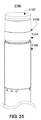
例えば、図31は、本開示のいくつかの実施形態による、シール3104、流体軸受要素3108、および自己調心特徴3106を有する、例証的ピストンアセンブリ3100の一部の斜視図を示す。ピストンアセンブリ3100は、ピストン面3102、シール3104、自己調心特徴3106、流体軸受要素3108、任意の他の好適な構成要素(図示せず)、または任意のそれらの組み合わせを含み得る。いくつかの実施形態では(図示されるように)、自己調心特徴3106は、シール3104の一部であり得る。例えば、シール3104は、軸受要素内の機械加工された段または他の好適な特徴であり得る、自己調心特徴3106を含み得る。いくつかの実施形態では(図示せず)、自己調心特徴3106は、ピストン面3102の一部であり得る。例えば、自己調心特徴3106は、段、1つ以上のスロット付きポケット、テーパ状部分、またはピストンアセンブリ3100内に含まれる他の特徴であり得る。任意の好適な流体源から供給されるガスは、内部流体通路(図示せず)を介して、ピストンアセンブリ3100内に分配され得、次いで、流体軸受要素3108の任意の好適な部分を通して流動し得る(図31では、多孔性として示されるが、任意の好適な軸受要素が、使用され得る)。
For example, FIG. 31 shows a perspective view of a portion of an
さらなる実施例では、図32は、本開示のいくつかの実施形態による、軸受要素3214、熱パイプ3250、および自己調心特徴3212を有する、ピストンアセンブリ3210と、変形可能シリンダライナ3232および冷却剤通路3236を有するシリンダ3230とを有する、例証的ピストン機関3200の断面図を示す。ピストンアセンブリ3210は、隙間3260を伴う、変形可能シリンダライナ3232によって生成されるボア内を平行移動するように構成され得る。好適な圧力に制御されたライナ流体の印加は、ポート3233を介して、通路3234に供給され、隙間3260を調節し得る。軸受流体は、通路3218に供給され、軸受要素3214から隙間3260に流入し、ボア内でピストンアセンブリ3210を調心することにおいて支援し得る。自己調心特徴3212は、調心ボア内でピストンアセンブリ3210を調心することにおいて支援し得る。好適な冷却剤が、シリンダ3230内の冷却剤通路3236に供給され、熱をシリンダ3230またはその一部から除去し得る。充填ポート3282を有する、熱パイプ3250は、ピストン面3202からピストンアセンブリ3210の別の部分に熱を伝達することにおいて支援し得る。ポート3270は、酸化性物質および/または燃料を供給する、駆動ガスを供給および/または除去する、あるいは排気をシリンダの区画から除去するために使用され得る。
In a further example, FIG. 32 illustrates a
いくつかの実施形態では、1つ以上のアプローチの組み合わせは、1つ以上の追加の考慮を要求し得る。例えば、いくつかの実施形態では、ピストンアセンブリは、ブローバイガスを使用して自己調心力を提供するように構成される、自己調心特徴と、軸受流体を隙間に提供するように構成される、軸受要素とを含み得る。自己調心特徴は、したがって、ある程度のブローバイガスが、隙間に沿って流動し、自己調心力を提供することを要求し得る。いくつかの条件下、隙間内のブローバイガスの流動は、隙間内の軸受流体の流動パターンを変えることによって、軸受要素の性能に影響を及ぼし得る。故に、自己調心特徴の背後に(燃焼区画に対して)軸受要素を有する、いくつかの実施形態では、ブローバイガスは、自己調心特徴に隣接する隙間の一部を横断後、但し、軸受要素に隣接する隙間の一部に流入する前に、隙間から離れるように経路指定され得る。さらに、いくつかの配列では、軸受要素は、自己調心特徴と、ピストン面まで延在し得る、軸受流体を向けるための孔の集合とを含み得る。故に、いくつかのそのような実施形態では、隙間から離れるようなブローバイガスの経路指定は、使用される必要はない。前述の実施例は、随意に、燃焼区画に加え、またはその代わりに、ガス駆動区画に適用され得る。 In some embodiments, a combination of one or more approaches may require one or more additional considerations. For example, in some embodiments, the piston assembly is configured to provide a self-aligning feature and bearing fluid to the gap that is configured to provide a self-aligning force using blow-by gas. Bearing elements. The self-aligning feature may therefore require that some blow-by gas flows along the gap and provides self-aligning force. Under some conditions, the flow of blow-by gas in the gap can affect the performance of the bearing element by changing the flow pattern of the bearing fluid in the gap. Thus, in some embodiments having a bearing element behind the self-aligning feature (relative to the combustion compartment), the blow-by gas has crossed a portion of the gap adjacent to the self-aligning feature, but the bearing It can be routed away from the gap before flowing into a portion of the gap adjacent to the element. Further, in some arrangements, the bearing element may include self-aligning features and a collection of holes for directing bearing fluid that may extend to the piston face. Thus, in some such embodiments, blow-by gas routing away from the gap need not be used. The foregoing embodiments can optionally be applied to a gas driven section in addition to or instead of the combustion section.
(隙間および/または他の特性の制御)
いくつかの実施形態では、ピストン機関の動作の1つ以上の側面は、温度、隙間、ピストン機関の任意の他の好適な特性、または任意のそれらの組み合わせに影響を及ぼすように制御あるいは別様に管理され得る。いくつかの実施形態では、ピストン機関の温度、圧力、または他の好適な特性の制御は、ピストン機関の隙間を管理することにおいて支援し得る。例えば、比較的に大きな温度差は、隙間に影響し得る、ピストン機関のいくつかの構成要素の膨張等の変形を生じさせ得る。温度差および/または温度場の制御は、変形を低減させることにおいて支援し得、故に、隙間を管理することにおいて支援し得る。隙間の管理は、隙間に影響を及ぼし得る、任意の他の好適な特性の管理を含み得る。
(Control of gaps and / or other properties)
In some embodiments, one or more aspects of the operation of the piston engine are controlled or otherwise modified to affect temperature, clearance, any other suitable characteristic of the piston engine, or any combination thereof. Can be managed. In some embodiments, control of piston engine temperature, pressure, or other suitable characteristics may assist in managing piston engine clearance. For example, relatively large temperature differences can cause deformations such as expansion of some components of the piston engine that can affect the clearance. Control of the temperature difference and / or temperature field can assist in reducing deformation and thus assist in managing gaps. Gap management may include management of any other suitable property that may affect the gap.
図33は、本開示のいくつかの実施形態による、ピストン機関3340のための例証的制御配列3300のブロック図である。制御システム3310は、ピストン機関3340に結合された1つ以上のセンサ3330と通信し得る。制御システム3310は、ピストン機関3340の状態(aspect)または特性を調節するために使用され得る、補助システム3320と通信するように構成され得る。いくつかの実施形態では、制御システム3310は、ユーザインターフェースシステム3350を介して、ユーザと相互作用するように構成され得る。
FIG. 33 is a block diagram of an
制御システム3310は、処理機器3312、通信インターフェース3314、センサインターフェース3316、制御インターフェース3318、任意の他の好適な構成要素またはモジュール、または任意のそれらの組み合わせを含み得る。制御システム3310は、少なくとも部分的に、1つ以上のコンピュータ、端末、制御ステーション、ハンドヘルドデバイス、モジュール、任意の他の好適なインターフェースデバイス、または任意のそれらの組み合わせにおいて実装され得る。いくつかの実施形態では、制御システム3310の構成要素は、図33に示されるように、通信バス3311を介して、通信可能に結合され得る。処理機器3312は、センサインターフェース3316によってセンサ3330から受信されるようなピストン機関3340に関する情報を処理し得る、プロセッサ(例えば、中央処理ユニット)、キャッシュ、ランダムアクセスメモリ(RAM)、読み取り専用メモリ(ROM)、任意の他の好適な構成要素、または任意のそれらの組み合わせを含み得る。センサインターフェース3316は、電力をセンサ3330、信号調整器、信号プリプロセッサ、任意の他の好適な構成要素、または任意のそれらの組み合わせに供給するための電力供給源を含み得る。例えば、センサインターフェース3316は、センサ3330からの信号を調整および事前処理するためのフィルタ、増幅器、サンプラ、およびアナログ/デジタルコンバータを含み得る。センサインターフェース3316は、有線接続(例えば、IEEE802.3イーサネット(登録商標)またはユニバーサルシリアルバスインターフェースを使用する)、無線結合(例えば、IEEE802.11「Wi−Fi」またはBluetooth(登録商標)を使用する)、光結合、誘導結合、任意の他の好適な結合、または任意のそれらの組み合わせであり得る、通信結合3319を介して、センサ3330と通信し得る。制御システム3310、より具体的には、処理機器3312は、関連時間尺度にわたってピストン機関3340の制御を提供するように構成され得る。例えば、1つ以上の温度の変化は、1つ以上の検出された機関動作パラメータに応答して制御可能であり得、制御は、ピストン機関の動作に関連する時間尺度(例えば、過加熱および/または構成要素故障を防止するために十分に高速な応答)に基づいて提供され得る。
The
センサ3330は、ピストン機関3340の任意の好適な特性または状態を感知するように構成され得る、任意の好適なタイプのセンサを含み得る。いくつかの実施形態では、センサは、補助システム3320のシステムのある状態および/または特性を感知するように構成される、1つ以上のセンサを含み得る。いくつかの実施形態では、センサ3330は、ピストン機関3340の構成要素、ピストン機関3340に導入され、またはそこから回収される流体、あるいは両方の温度を感知するように構成される、温度センサ(例えば、熱電対、抵抗温度検出器、サーミスタ、または光学温度センサ)を含み得る。いくつかの実施形態では、センサ3330は、ピストン機関3340の区画(例えば、燃焼区画、またはガス駆動区画)内の圧力、ピストン機関3340に導入され、またはそこから回収される流体、あるいは両方の圧力を感知するように構成される、1つ以上の圧力センサ(例えば、圧電圧力変換器)を含み得る。いくつかの実施形態では、センサ3330は、張力、圧縮力、または剪断力等のピストン機関3340内の力(例えば、摩擦力または他の関連力情報を示し得る)を感知するように構成される、1つ以上の力センサ(例えば、圧電力変換器)を含み得る。いくつかの実施形態では、センサ3330は、電圧、電流、仕事出力および/または入力(例えば、電圧によって乗算される電流)、ピストン機関3340および/または補助システム3320の任意の他の好適な電気特性、あるいは任意のそれらの組み合わせを感知するように構成される、1つ以上の電流および/または電圧センサ(例えば、ピストン機関3340のLEMに結合された電流計および/または電圧計)を含み得る。
Sensor 3330 may include any suitable type of sensor that may be configured to sense any suitable characteristic or condition of
制御インターフェース3318は、補助システム3320のうちの1つ以上と通信し得るための有線接続(例えば、IEEE802.3イーサネット(登録商標)またはユニバーサルシリアルバスインターフェースを使用する)、無線結合(例えば、IEEE802.11「Wi−Fi」、Bluetooth(登録商標)、または他のRF通信プロトコルを使用する)、光結合、誘導結合、任意の他の好適な結合、または任意のそれらの組み合わせを含み得る。いくつかの実施形態では、制御インターフェース3318は、デジタル/アナログコンバータを含み、アナログ制御信号を補助システム3320の一部または全部に提供し得る。
The
補助システム3320は、冷却システム3322、圧力制御システム3324、ガス駆動制御システム3326、および/または任意の他の好適な制御システム3328を含み得る。冷却/加熱システム3322は、ポンプ、流体リザーバ、圧力調整器、バイパス、ラジエータ、流体導管、電力回路(例えば、電気加熱器用)、任意の他の好適な構成要素、または任意のそれらの組み合わせを含み、冷却、加熱、または両方をピストン機関3340に提供し得る。圧力制御システム3324は、ポンプ、コンプレッサ、流体リザーバ、圧力調整器、流体導管、任意の他の好適な構成要素、または任意のそれらの組み合わせを含み、圧力制御された流体をピストン機関3340に供給(および、随意に、受容)し得る。ガス駆動制御システム3326は、コンプレッサ、ガスリザーバ、圧力調整器、流体導管、任意の他の好適な構成要素、または任意のそれらの組み合わせを含み、駆動ガスをピストン機関3340に供給し(および、随意に、受け取り)得る。いくつかの実施形態では、他のシステム3328は、例えば、カム作動システムまたはソレノイドシステム等の弁システムを含み、酸化性物質および/または燃料をピストン機関3340に供給し得る。
The auxiliary system 3320 may include a
ユーザインターフェース3315は、ユーザインターフェースシステム3350のうちの1つ以上と通信するための有線接続(例えば、IEEE802.3イーサネット(登録商標)、またはユニバーサルシリアルバスインターフェース、チップ−リング−シールRCAタイプ接続を使用する)、無線結合(例えば、IEEE802.11「Wi−Fi」、赤外線、またはBluetooth(登録商標)を使用する)、光結合、誘導結合、任意の他の好適な結合、または任意のそれらの組み合わせを含み得る。ユーザインターフェースシステム3350は、ディスプレイ3352、キーボード3354、マウス3356、オーディオデバイス3358、任意の他の好適なユーザインターフェースデバイス、または任意のそれらの組み合わせを含み得る。ディスプレイ3352は、例えば、ブラウン管画面、液晶ディスプレイ画面、発光ダイオードディスプレイ画面、プラズマディスプレイ画面、グラフィック、テキスト、画像、または他の視覚表示をユーザに提供し得る、任意の他の好適なディスプレイ画面、あるいはその画面の任意の組み合わせ等のディスプレイ画面を含み得る。いくつかの実施形態では、ディスプレイ3352は、例えば、1つ以上のソフトコマンドをディスプレイ画面上に提示することによって、ユーザとの触知的相互作用を提供し得る、タッチスクリーンを含み得る。ディスプレイ3352は、ピストン機関3340(例えば、ピストン機関3340の特性の時系列)、制御システム3310、補助システム3320、ユーザインターフェースシステム3350に関する任意の好適な情報、任意の他の好適な情報、または任意のそれらの組み合わせを表示し得る。キーボード3354は、QWERTYキーボード、数字キーパッド、ハードコマンドボタンの任意の他の好適な集合、または任意のそれらの組み合わせを含み得る。マウス3356は、ディスプレイ画面上に表示されるグラフィカルユーザインターフェース上のカーソルまたはアイコンを制御し得る、任意の好適な指示デバイスを含み得る。マウス3356は、ハンドヘルドデバイス(例えば、2次元または3次元で移動可能)、タッチパッド、任意の他の好適な指示デバイス、または任意のそれらの組み合わせを含み得る。オーディオデバイス3358は、マイクロホン、スピーカ、ヘッドホン、オーディオ信号を提供および/または受信するための任意の他の好適なデバイス、あるいは任意のそれらの組み合わせを含み得る。例えば、オーディオデバイス3358は、マイクロホンを含み得、処理機器3312は、ユーザがマイクロホンに話しかけることによって生じる、ユーザインターフェース3315を介して受信された音声コマンドを処理し得る。
いくつかの実施形態では、制御システム3310は、1つ以上のユーザ入力を受信することによって、手動制御を提供するように構成され得る。例えば、いくつかの実施形態では、制御システム3310は、センサフィードバックに基づいて、自動制御設定を上書きし、ユーザインターフェースシステム3350への1つ以上のユーザ入力に基づいて、制御信号を補助システム3320に出し得る。さらなる実施例では、ユーザは、1つ以上の制御変数(例えば、温度、圧力、流量、仕事入力/出力、または他の変数)のための設定点値を入力し得、制御システム3310は、設定点値に基づいて、制御アルゴリズムを実行し得る。
In some embodiments, the
いくつかの実施形態では、動作特性(すなわち、ピストン機関3340または補助システム3320の所望の特性値の集合)は、製造業者、ユーザ、または両方によって事前に定義され得る。例えば、特定の動作特性は、処理機器3312のメモリ内に記憶され得、1つ以上の制御信号を提供するようにアクセスされ得る。いくつかの実施形態では、動作特性のうちの1つ以上は、ユーザによって変更され得る。配列3300は、それらの動作特性を維持、調節、または別様に管理するために使用され得る。
In some embodiments, operational characteristics (ie, a set of desired characteristic values for
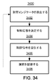
図34は、本開示のいくつかの実施形態による、ピストン機関の隙間を調節するための例証的ステップの流れ図3400である。 FIG. 34 is a flow diagram 3400 of illustrative steps for adjusting piston engine clearances according to some embodiments of the present disclosure.
ステップ3402は、センサ3330を使用して、隙間インジケータを検出するステップを含み得る。隙間インジケータは、(例えば、冷却剤、加熱流体、シリンダ、ピストン、または他の構成要素、またはその一部の)温度、圧力、力、距離(例えば、隙間)、仕事相互作用(例えば、電磁仕事出力)、材料(例えば、ブローバイまたはその特性)、任意の他の好適な検出可能特性、または任意のそれらの組み合わせであり得る。センサインターフェース3316は、センサ3330からの隙間インジケータを受信、調整、および/または事前処理し、センサ信号を処理機器3312に出力し得る。いくつかの実施形態では、隙間インジケータは、記憶され、ピストン機関の1つ以上の動作条件と相関され得る。例えば、シリンダ温度は、燃料流と相関され、数式または表として記憶され得る。故に、ステップ3402は、ピストン機関の1つ以上の動作条件を検出することと、さらなる処理のために使用され得る、記憶されたシリンダ温度値を呼び出すこととを含み得る。
ステップ3404は、処理機器3312が、少なくとも部分的に、ステップ3402の検出された隙間インジケータに基づいて、制御応答を決定することを含み得る。処理機器3312は、センサ信号をセンサインターフェース3316から受信して、センサ信号に1つ以上の処理機能を行ない得る。処理機能は、センサ信号値を方程式または他の数式に入力すること、ルックアップテーブルまたは他のデータベース内のセンサ信号値を使用すること、任意の他の好適な処理、あるいは任意のそれらの組み合わせを含み得る。処理機器3312は、1つ以上の処理機能の出力に基づいて、制御応答を決定し得る。例えば、計算された値は、事前に定義された閾値と比較され、好適な制御応答を決定し得る。さらなる実施例では、1つ以上の計算された値が、制御アルゴリズム(例えば、比例−積分−微分(PID)制御アルゴリズム)に入力され得、1つ以上の制御信号値が、決定され得る。
ステップ3406は、処理機器3312が、制御インターフェース3318を使用して、少なくとも部分的に、ステップ3404の決定された制御応答に基づいて、制御信号を補助システム3320のうちの1つ以上に提供することを含み得る。制御信号は、電気信号(例えば、有線ケーブルを使用する)、電磁信号(例えば、IEEE802.11「Wi−Fi」またはBluetooth(登録商標)受信機/送信機を使用する)、光信号(例えば、光ファイバケーブルを使用する)、誘導信号(例えば、好適な伝導性コイルを使用する)、または他の好適な信号タイプとして提供され得る、アナログ信号、デジタル信号、またはそれらの組み合わせ(例えば、デジタルタイミング信号を伴うアナログ信号)であり得る。
ステップ3408は、ステップ3406において制御信号を受信した補助システム3320のうちの1つ以上が、ピストン機関3340の隙間または他の特性を調節することを含み得る。補助システム3320のうちの1つ以上は、提供された制御信号に基づいて、圧力、温度、流量、流路、電流、電圧、電力を調節する、任意の他の好適な調節を行なう、または任意のそれらの組み合わせを行ない得る。図34の点線矢印によって示されるように、ステップ3402−3408の一部または全部は、繰り返され、閉ループ制御を可能にし得る。いくつかの実施形態では、開ループアプローチが使用され得、その場合、ステップ3402は、省略され得(但し、必要ではない)、ステップ3404−3408は、ループ化せずに、行なわれる。
いくつかの配列では、ピストン機関のシリンダおよび/またはピストンアセンブリあるいはその中に含まれる流体の温度場は、隙間の主要かつ便宜なインジケータであり得、温度場は、故に、隙間を調節するように能動的に調節され得る。例証的実施例では、ステップ3402は、例えば、シリンダ温度または(例えば、ピストン機関のシリンダの冷却剤通路に提供される冷却剤の)冷却剤温度等の温度を検出することを含み得る。ステップ3404は、温度場を調節し、隙間を維持または別様に管理する方法を決定することを含み得る一方、ステップ3406は、対応する制御信号を適切な補助システムに提供することを含み得る。例えば、シリンダ温度は、冷却剤流量を減少させることによって上昇される得、これは、熱膨張を介して、隙間を拡大させ得る。さらなる実施例では、シリンダ温度は、冷却剤流量を増加させることによって低下され得、これは、熱収縮を介して、隙間を縮小させ得る。さらなる実施例では、2セット以上の流体通路内の冷却剤または加熱流体の流量が調節され、シリンダのゾーンの温度場を制御し得る(例えば、図22参照)。前述の実施例を参照すると、冷却剤または加熱流体流量は、ステップ3406の制御信号に基づいて、例えば、流量制御弁、ポンプ回転速度、バイパス流量制御弁、圧力調整器、流量を制御するための任意の他の好適な制御デバイス、または任意のそれらの組み合わせを調節することによって、調節され得る。さらなる例証的実施例では、ステップ3402は、例えば、ピストン機関のシリンダ内の熱パイプの温度(例えば、熱パイプまたはその中の熱パイプ流体の温度)等の温度を検出することを含み得る。ステップ3404は、温度場を調節し、隙間を維持または別様に管理する方法を決定することを含み得る一方、ステップ3406は、対応する制御信号を適切な補助システムに提供することを含み得る。例えば、熱パイプ温度は、熱パイプ内の流体の圧力を増加させることによって(例えば、流体を熱パイプに追加する、または熱パイプの容積を縮小させることによって)上昇され得、これは、隙間を拡大させ得る。さらなる実施例では、熱パイプ温度は、熱パイプ圧力を減少させることによって(例えば、流体を熱パイプから除去することによって、または熱パイプの容積を拡大させることによって)、低下され得、これは、隙間を縮小させ得る。前述の実施例を参照すると、熱パイプ(例えば、流体ポートまたは他の調節可能特徴を有する)内の流体の特性は、ステップ3406の制御信号に基づいて、例えば、流量制御弁、圧力調整器、逆止弁、熱パイプ圧力を制御するための任意の他の好適な制御デバイスおよび熱パイプ内に含まれる好適な流体ポート、または任意のそれらの組み合わせを調節することによって、調節され得る。
In some arrangements, the temperature field of the cylinder and / or piston assembly of the piston engine or the fluid contained therein can be a primary and convenient indicator of the gap, so that the temperature field can thus adjust the gap. It can be actively adjusted. In an illustrative example,
図35は、本開示のいくつかの実施形態による、ピストン機関の1つ以上の特性を調節するための例証的ステップの流れ図3500である。
FIG. 35 is a
いくつかの実施形態では、隙間インジケータは、センサ3330を使用して検出され得る。センサインターフェース3316は、未加工信号をセンサ3330から受信し、センサ信号を処理機器3312に提供し得る。例えば、ステップ3502は、シリンダの一部(例えば、燃焼区画の近傍)と接触して、またはその近傍に位置付けられる、熱電対等の温度センサを使用して、ピストン機関3340のシリンダ温度を検出することを含み得る。いくつかの状況では、シリンダ温度の上昇は、隙間に影響を及ぼし得る、不十分な冷却を示し得る。さらなる実施例では、ステップ3504は、ピストンアセンブリの一部(例えば、ピストン面の近傍)と接触して、またはその近傍に位置付けられる、熱電対等の温度センサを使用して、ピストン機関3340のピストン温度を検出することを含み得る。いくつかの状況では、ピストン温度の上昇は、隙間に影響を及ぼし得る、不十分な冷却を示し得る。さらなる実施例では、ステップ3506は、流体と接触して、またはその近傍に位置付けられる、熱電対等の温度センサ(例えば、好適な測定ポートを使用して、流体導管内に挿入される)を使用して、ピストン機関3340の流体(例えば、ピストン機関3340に供給され、そこから回収され得る、冷却剤、加熱流体、または排気)温度を検出することを含み得る。例えば、いくつかの状況では、冷却剤温度の上昇は、隙間に影響を及ぼし得る、不十分な冷却を示し得る。さらなる実施例では、ステップ3507は、冷却剤と接触して、またはその近傍に位置付けられる、圧電変換器等の圧力センサ(例えば、好適な測定ポートを使用して、導管内に挿入される)を使用して、燃焼区画、ガス駆動区画、隙間、冷却剤、加熱流体、ピストン機関3340の任意の他の流体、または任意のそれらの組み合わせの圧力を検出することを含み得る。さらなる実施例では、ステップ3508は、構成要素の界面と接触して、またはその近傍に位置付けられる、熱電対等の圧電変換器および/または温度センサ等の力センサを使用して、ピストン機関3340の構成可能間の摩擦を検出することを含み得る。いくつかの状況では、摩擦の影響の増加(例えば、摩擦力、または摩擦発生熱)は、不十分な隙間を示し得る。さらなる実施例では、ステップ3509は、ピストン機関3340の隙間の1つ以上の特性を検出することを含み得る。1つ以上の特性は、隙間の厚さ(例えば、誘導センサ等の近接センサを使用して)、隙間の非対称性(例えば、誘導センサ等の複数の近接センサを使用して)、ブローバイ温度(例えば、温度センサを使用して)、ブローバイ圧力(例えば、圧力センサを使用して)、ブローバイ組成物(例えば、光吸収センサ等のガスセンサを使用して)、および他の好適な特性、または任意のそれらの組み合わせを含み得る。さらなる実施例では、ステップ3510は、電磁センサ(例えば、電圧計、電流計、または電力測定器)、圧力変換器(例えば、図示MEP、軸MEP、および/または摩擦MEP等の平均有効圧力(MEP)を計算するために、圧力を検出する)、または他の好適なセンサを使用して、ピストン機関3340の仕事相互作用を検出し、隙間の指標を提供することを含み得る。いくつかの状況では、仕事出力の減少または仕事入力要件の増加は、不十分および/または過剰な隙間を示し得る。
In some embodiments, the gap indicator can be detected using sensor 3330.
ステップ3512は、処理機器3312が、少なくとも部分的に、ステップ3502、3504、3506、3508、および3510の検出された隙間インジケータの一部または全部に基づいて、制御応答を決定することを含み得る。処理機器3312は、センサ信号をセンサインターフェース3316から受信し、センサ信号に1つ以上の処理機能を行ない得る。処理機能は、センサ信号値を方程式または他の数式に入力すること、ルックアップテーブルまたは他のデータベース内のセンサ信号値を使用すること、任意の他の好適な処理、または任意のそれらの組み合わせを含み得る。処理機器3312は、1つ以上の処理機能の出力に基づいて、制御応答を決定し得る。例えば、計算された値は、事前に定義された閾値と比較され、好適な制御応答を決定し得る。さらなる実施例では、1つ以上の計算された値が、制御アルゴリズム(例えば、PID制御アルゴリズム)に入力され得、1つ以上の制御信号値が、決定され得る。
Step 3512 may include the
ステップ3514は、処理機器3312が、制御インターフェース3318を使用して、少なくとも部分的に、ステップ3512の決定された制御応答に基づいて、制御信号を補助システム3320のうちの1つ以上に提供することを含み得る。制御信号は、電気信号(例えば、有線ケーブルを使用する)、電磁信号(例えば、IEEE802.11「Wi−Fi」またはBluetooth(登録商標)受信機/送信機を使用する)、光信号(例えば、光ファイバケーブルを使用する)、誘導信号(例えば、好適な伝導性コイルを使用する)、または他の好適な信号タイプとして提供され得る、アナログ信号、デジタル信号、またはそれらの組み合わせ(例えば、デジタルタイミング信号を伴う、アナログ信号)であり得る。
いくつかの実施形態では、ステップ3514の制御信号は、ピストン機関3340の隙間または他の特性を調節し得る、補助システム3320のうちの1つ以上によって受信され得る。例えば、ステップ3516によって示されるように、ステップ3514の制御信号は、冷却剤または加熱流体の温度を調節し得る、冷却/加熱システム3322によって受信され得る。冷却/加熱システム3322は、制御信号に従って、ステップ3516において、ピストン機関3340に提供される冷却剤または加熱流体温度を調節し得る、サーモスタットまたは他の温度調整デバイスを含み得る。さらなる実施例では、ステップ3516は、1つ以上のスロットル特性を調節し、絞り調節された流体の温度を制御する、冷却/加熱システム3322を含み得る。さらなる実施例では、ステップ3518によって示されるように、ステップ3514の制御信号は、冷却剤または加熱流体の流量を調節し得る、冷却/加熱システム3322によって受信され得る。冷却/加熱システム3322は、制御信号に従って、ステップ3518において、ピストン機関3340に提供される冷却剤または加熱流体の流量を調節し得る、流量調整器(例えば、絞り弁またはオリフィス)を含み得る。さらなる実施例では、ステップ3518は、1つ以上のスロットル特性を調節し、絞り調節された流体の流量を制御する、冷却/加熱システム3322を含み得る。さらなる実施例では、ステップ3520によって示されるように、ステップ3514の制御信号は、ステップ3520において、冷却剤または加熱流体の流路を調節し得る、冷却/加熱システム3322によって受信され得る。冷却/加熱システム3322は、制御信号に従って、1つ以上の流体通路へおよび/またはそこからピストン機関3340に提供される冷却剤または加熱流体の流量を指向および制御し得る、1つ以上の弁、スロットル、または他の流量制御デバイスを含み得る。さらなる実施例では、ステップ3522によって示されるように、ステップ3514の制御信号は、ステップ3522において、熱パイプの1つ以上の特性を調節し得る、圧力制御システム3324によって受信され得る。圧力制御システム3324は、1つ以上の弁および流体リザーバを含み得、制御信号に従って、ピストン機関3340の熱パイプ内の流体の圧力を調節し得る(例えば、流体を熱パイプに供給する、またはそこから除去することによって)。さらなる実施例では、ステップ3524によって示されるように、ステップ3514の制御信号は、ピストン機関3340の変形可能シリンダライナへのライナ流体の圧力および/または流量を調節し得る、圧力制御システム3324によって受信され得る。圧力制御システム3324は、1つ以上の弁、ポンプ、および流体リザーバを含み得、制御信号に従って、ステップ3524において、ライナ流体の圧力および/または流量、故に、ピストン機関3340の変形可能シリンダライナの変形を調節し得る(例えば、ライナ通路内の圧力を増加または減少させることによって)。さらなる実施例では、ステップ3526によって示される、ステップ3514の制御信号は、ピストン機関3340の1つ以上の特性を調節し得る、他のシステム3328によって受信され得る。他のシステム3328は、任意の好適な構成要素を含み、少なくとも部分的に、制御信号に基づいて、ステップ3526において、ピストン機関3340の1つ以上の特性の調節を達成し得る。例えば、他のシステム3328は、電力をピストン機関3340内に埋め込まれた1つ以上の電気抵抗加熱器に提供するように構成される、電子機器を含み得、ステップ3526は、電気抵抗加熱器に供給される、電圧、電流、または両方を調節することを含み得る。
In some embodiments, the control signal of
流れ図3400−3500の例証的ステップのいずれも、本開示に従って他のステップと組み合わせられる、省略される、再配列される、または別様に改変され得る。 Any of the illustrative steps in flowcharts 3400-3500 may be combined, omitted, rearranged, or otherwise modified in combination with other steps in accordance with this disclosure.
前述は、単に、本開示の原理の例証であって、種々の修正が、本開示の範囲から逸脱することなく、当業者によって成され得る。前述の説明される実施形態は、限定ではなく、例証の目的のために提示される。本開示はまた、本明細書に明示的に説明されるもの以外の多くの形態をとることができる。故に、本開示は、明示的に開示される方法、システム、および装置に限定されず、以下の請求項の精神内にある、その変形例および修正を含むことが意図されることを強調されたい。 The foregoing is merely illustrative of the principles of the present disclosure and various modifications can be made by those skilled in the art without departing from the scope of the present disclosure. The foregoing described embodiments are presented for purposes of illustration and not limitation. The present disclosure can also take many forms other than those explicitly described herein. Therefore, it should be emphasized that this disclosure is not limited to the explicitly disclosed methods, systems, and apparatus, but is intended to include variations and modifications thereof that are within the spirit of the following claims. .
いくつかの実施形態では、同軸のピストンアセンブリとピストン機関のシリンダとの間の隙間は、制御され得る。例えば、隙間の温度、圧力、仕事相互作用、および/または他の好適なインジケータ等の少なくとも1つのインジケータが、1つ以上のセンサを使用して検出され得る。制御応答は、少なくとも部分的に、インジケータに基づいて、処理機器によって決定され得る。処理機器は、制御インターフェースを使用して、少なくとも部分的に、制御応答に基づいて、制御信号をピストン機関の少なくとも1つの補助システムに提供し得る。少なくとも1つの補助システムは、少なくとも部分的に、制御信号に基づいて、隙間を調節し得る。
本発明はさらに、例えば、以下を提供する。
(項目1)
アセンブリであって、
ボアと、流体を含むことが可能な区画とを備えているシリンダと、
前記ボアの軸に沿って軸方向に平行移動可能なピストンアセンブリであって、前記ピストンアセンブリは、ピストン面を備えている、ピストンアセンブリと、
前記ピストンアセンブリと前記シリンダとの間に形成されている隙間に軸受流体の流動を提供するように構成されている少なくとも1つの軸受要素と
を備えている、アセンブリ。
(項目2)
前記軸受要素は、前記ピストンアセンブリに取り付けられ、前記ピストンアセンブリは、送給通路をさらに備え、前記送給通路は、前記軸受流体を流体源から受け取り、前記軸受流体を前記軸受要素に提供するように構成されている、項目1に記載のアセンブリ。
(項目3)
前記軸受要素は、多孔性環状要素を備え、前記多孔性環状要素は、前記軸受流体が細孔を通り前記送給通路から前記隙間に半径方向外向きに流動することを可能にする、項目2に記載のアセンブリ。
(項目4)
前記軸受要素は、1つ以上の半径方向孔を備え、前記1つ以上の半径方向孔は、前記軸受流体が前記送給通路から前記隙間に半径方向外向きに流動することを可能にするように構成されている、項目2に記載のアセンブリ。
(項目5)
前記軸受要素は、前記シリンダに取り付けられ、前記シリンダは、送給通路をさらに備え、前記送給通路は、軸受流体を流体源から受け取り、前記軸受流体を前記軸受要素に提供するように構成されている、項目1に記載のアセンブリ。
(項目6)
前記軸受要素は、黒鉛要素、機械加工された特徴を伴う金属要素、焼結された金属要素、多孔性セラミック要素、および非多孔性セラミック要素のうちの少なくとも1つを含む、項目1に記載のアセンブリ。
(項目7)
前記軸受流体は、空気を含む、項目1に記載のアセンブリ。
(項目8)
前記区画内に含まれる流体は、ガスを含み、前記ピストンアセンブリは、前記区画からのブローバイガスの流動を使用して自己調心を提供する特徴または構成要素をさらに備えている、項目1に記載のアセンブリ。
(項目9)
前記区画内に含まれる流体は、ガスを含み、前記アセンブリは、ブローバイガスの流動を前記軸受要素に隣接する隙間の一部から離れるように経路指定するように構成されている1つ以上の通路をさらに備えている、項目1に記載のアセンブリ。
(項目10)
前記区画内に含まれる流体は、ガスを含み、前記ピストンアセンブリは、ブローバイガスの流動に影響を及ぼすように構成されているラビリンスシールをさらに備えている、項目1に記載のアセンブリ。
(項目11)
前記ラビリンスシールは、複数の円周方向溝を備えている、項目10に記載のアセンブリ。
(項目12)
前記軸受流体の流動は、前記隙間内に流体層を形成するように構成されている、項目1に記載のアセンブリ。
(項目13)
前記流体層は、前記ボアの軸を中心とした前記ピストンアセンブリの調心を支援する、項目12に記載のアセンブリ。
(項目14)
前記区画は、燃焼区画およびガス駆動区画のうちの少なくとも1つを備え、前記ピストン面は、前記区画に接触するように構成されている、項目1に記載のアセンブリ。
(項目15)
前記アセンブリは、無給油動作のために構成されている、項目1に記載のアセンブリ。
(項目16)
流体を含むことが可能な区画を備えているシリンダの軸に沿って軸方向に平行移動するように構成されているアセンブリであって、前記アセンブリは、
前記区画に接触するように構成されているピストン面と、
前記アセンブリの表面への軸受流体の外向流を提供するように構成されている少なくとも1つの軸受要素と
を備え、
前記アセンブリは、前記シリンダと接触しない、アセンブリ。
(項目17)
送給通路をさらに備え、前記送給通路は、前記軸受流体を流体源から受け取り、前記軸受流体を前記軸受要素に提供するように構成されている、項目16に記載のアセンブリ。
(項目18)
前記軸受要素は、多孔性環状要素を備え、前記多孔性環状要素は、前記軸受流体が細孔を通り前記送給通路から前記アセンブリの表面に半径方向外向きに流動することを可能にする、項目17に記載のアセンブリ。
(項目19)
前記軸受要素は、1つ以上の半径方向孔を備え、前記1つ以上の半径方向孔は、前記軸受流体が前記送給通路から前記アセンブリの表面に半径方向外向きに流動することを可能にするように構成されている、項目17に記載のアセンブリ。
(項目20)
前記区画内に含まれる流体は、ガスを含み、前記ピストンアセンブリは、前記区画からのブローバイガスの流動を使用して自己調心を提供する特徴をさらに備えている、項目16に記載のアセンブリ。
(項目21)
前記区画内に含まれる流体は、ガスを含み、前記アセンブリは、ブローバイガスの流動に影響を及ぼすように構成されているラビリンスシールをさらに備えている、項目16に記載のアセンブリ。
(項目22)
前記区画内に含まれる流体は、ガスを含み、前記アセンブリは、前記流体区画からのブローバイガスの流動が前記アセンブリの表面から離れるように経路指定するように構成されている1つ以上の通路をさらに備えている、項目16に記載のアセンブリ。
(項目23)
前記軸受流体は、空気を含む、項目16に記載のアセンブリ。
(項目24)
前記区画は、燃焼区画およびガス駆動区画のうちの少なくとも1つを備え、前記ピストン面は、前記区画に接触するように構成されている、項目16に記載のアセンブリ。
(項目25)
前記アセンブリは、無給油動作のために構成されている、項目16に記載のアセンブリ。
(項目26)
ピストン機関のシリンダであって、前記シリンダは、
ピストンを格納可能なボアであって、前記ピストンは、前記ボアの軸に沿って移動可能である、ボアと、
軸受流体の流動を前記ボアに提供するように構成されている少なくとも1つの軸受要素と
を備え、
前記ピストンは、前記シリンダと接触しない、シリンダ。
(項目27)
送給通路をさらに備え、前記送給通路は、前記軸受流体を流体源から受け取り、前記軸受流体を前記軸受要素に提供するように構成されている、項目26に記載のシリンダ。
(項目28)
前記軸受要素は、多孔性環状要素を備え、前記多孔性環状要素は、前記軸受流体が細孔を通り前記送給通路から前記ボアに半径方向内向きに流動することを可能にするように構成されている、項目27に記載のシリンダ。
(項目29)
前記軸受要素は、1つ以上の半径方向孔を備え、前記1つ以上の半径方向孔は、前記軸受流体が前記送給通路から前記ボアに半径方向内向きに流動することを可能にするように構成されている、項目27に記載のシリンダ。
(項目30)
前記シリンダは、無給油動作のために構成されている、項目26に記載のシリンダ。
In some embodiments, the clearance between the coaxial piston assembly and the cylinder of the piston engine can be controlled. For example, at least one indicator, such as gap temperature, pressure, work interaction, and / or other suitable indicator, may be detected using one or more sensors. The control response may be determined by the processing equipment based at least in part on the indicator. The processing equipment may use the control interface to provide a control signal to at least one auxiliary system of the piston engine based at least in part on the control response. The at least one auxiliary system may adjust the gap based at least in part on the control signal.
The present invention further provides, for example:
(Item 1)
An assembly,
A cylinder having a bore and a compartment capable of containing fluid;
A piston assembly axially translatable along an axis of the bore, the piston assembly comprising a piston face;
At least one bearing element configured to provide a bearing fluid flow to a gap formed between the piston assembly and the cylinder;
An assembly.
(Item 2)
The bearing element is attached to the piston assembly, the piston assembly further comprising a feed passage, wherein the feed passage receives the bearing fluid from a fluid source and provides the bearing fluid to the bearing element. The assembly according to item 1, wherein the assembly is configured as follows.
(Item 3)
The bearing element comprises a porous annular element, the porous annular element allowing the bearing fluid to flow radially outwardly from the feed passage through the pores into the gap. The assembly described in.
(Item 4)
The bearing element includes one or more radial holes, the one or more radial holes allowing the bearing fluid to flow radially outward from the feed passage into the gap.
(Item 5)
The bearing element is attached to the cylinder, the cylinder further comprising a feed passage, wherein the feed passage is configured to receive a bearing fluid from a fluid source and provide the bearing fluid to the bearing element. The assembly according to item 1, wherein:
(Item 6)
The bearing element of claim 1, wherein the bearing element comprises at least one of a graphite element, a metal element with machined features, a sintered metal element, a porous ceramic element, and a non-porous ceramic element. assembly.
(Item 7)
The assembly of claim 1, wherein the bearing fluid comprises air.
(Item 8)
The fluid contained within the compartment includes gas, and the piston assembly further comprises a feature or component that provides self-alignment using a flow of blow-by gas from the compartment. Assembly.
(Item 9)
The fluid contained within the compartment includes a gas, and the assembly is configured to route the flow of blow-by gas away from a portion of the gap adjacent to the bearing element. The assembly according to item 1, further comprising:
(Item 10)
The assembly of claim 1, wherein the fluid contained within the compartment comprises a gas and the piston assembly further comprises a labyrinth seal configured to affect the flow of blow-by gas.
(Item 11)
The assembly of claim 10, wherein the labyrinth seal comprises a plurality of circumferential grooves.
(Item 12)
The assembly of claim 1, wherein the flow of the bearing fluid is configured to form a fluid layer within the gap.
(Item 13)
13. An assembly according to item 12, wherein the fluid layer assists in alignment of the piston assembly about the axis of the bore.
(Item 14)
The assembly of claim 1, wherein the compartment comprises at least one of a combustion compartment and a gas driven compartment, and wherein the piston face is configured to contact the compartment.
(Item 15)
The assembly of claim 1, wherein the assembly is configured for oilless operation.
(Item 16)
An assembly configured to translate axially along an axis of a cylinder having a compartment capable of containing fluid, the assembly comprising:
A piston surface configured to contact the compartment;
At least one bearing element configured to provide an outward flow of bearing fluid to a surface of the assembly;
With
The assembly does not contact the cylinder.
(Item 17)
The assembly of claim 16, further comprising a feed passage, wherein the feed passage is configured to receive the bearing fluid from a fluid source and to provide the bearing fluid to the bearing element.
(Item 18)
The bearing element comprises a porous annular element, the porous annular element allowing the bearing fluid to flow radially outwardly from the feed passage to the surface of the assembly; Item 18. The assembly according to item 17.
(Item 19)
The bearing element includes one or more radial holes, which allow the bearing fluid to flow radially outward from the feed passage to the surface of the assembly. 18. An assembly according to item 17, wherein the assembly is configured to.
(Item 20)
The assembly of claim 16, wherein the fluid contained within the compartment comprises a gas, and the piston assembly further comprises a feature that provides self-alignment using a flow of blow-by gas from the compartment.
(Item 21)
The assembly of claim 16, wherein the fluid contained in the compartment comprises a gas, and the assembly further comprises a labyrinth seal configured to affect the flow of blow-by gas.
(Item 22)
The fluid contained within the compartment includes a gas, and the assembly includes one or more passages configured to route the flow of blow-by gas from the fluid compartment away from the surface of the assembly. The assembly according to item 16, further comprising:
(Item 23)
The assembly of claim 16, wherein the bearing fluid comprises air.
(Item 24)
17. An assembly according to item 16, wherein the compartment comprises at least one of a combustion compartment and a gas driven compartment, and the piston surface is configured to contact the compartment.
(Item 25)
The assembly of claim 16, wherein the assembly is configured for oilless operation.
(Item 26)
A cylinder of a piston engine,
A bore capable of retracting a piston, wherein the piston is movable along an axis of the bore; and
At least one bearing element configured to provide a flow of bearing fluid to the bore;
With
The piston is a cylinder that does not contact the cylinder.
(Item 27)
27. A cylinder according to item 26, further comprising a feed passage, wherein the feed passage is configured to receive the bearing fluid from a fluid source and to provide the bearing fluid to the bearing element.
(Item 28)
The bearing element comprises a porous annular element configured to allow the bearing fluid to flow radially inward from the feed passage through the pores to the bore. 28. The cylinder according to item 27.
(Item 29)
The bearing element comprises one or more radial holes, the one or more radial holes allowing the bearing fluid to flow radially inward from the feed passage to the bore. 28. The cylinder according to item 27.
(Item 30)
27. A cylinder according to item 26, wherein the cylinder is configured for an oil-free operation.
Claims (30)
ボアと、流体を含むことが可能な区画とを備えているシリンダと、
前記ボアの軸に沿って軸方向に平行移動可能なピストンアセンブリであって、前記ピストンアセンブリは、ピストン面を備えている、ピストンアセンブリと、
前記ピストンアセンブリと前記シリンダとの間に形成されている隙間に軸受流体の流動を提供するように構成されている少なくとも1つの軸受要素と
を備えている、アセンブリ。 An assembly,
A cylinder having a bore and a compartment capable of containing fluid;
A piston assembly axially translatable along an axis of the bore, the piston assembly comprising a piston face;
An assembly comprising: at least one bearing element configured to provide a flow of bearing fluid to a gap formed between the piston assembly and the cylinder.
前記区画に接触するように構成されているピストン面と、
前記アセンブリの表面への軸受流体の外向流を提供するように構成されている少なくとも1つの軸受要素と
を備え、
前記アセンブリは、前記シリンダと接触しない、アセンブリ。 An assembly configured to translate axially along an axis of a cylinder having a compartment capable of containing fluid, the assembly comprising:
A piston surface configured to contact the compartment;
At least one bearing element configured to provide an outward flow of bearing fluid to a surface of the assembly;
The assembly does not contact the cylinder.
ピストンを格納可能なボアであって、前記ピストンは、前記ボアの軸に沿って移動可能である、ボアと、
軸受流体の流動を前記ボアに提供するように構成されている少なくとも1つの軸受要素と
を備え、
前記ピストンは、前記シリンダと接触しない、シリンダ。 A cylinder of a piston engine,
A bore capable of retracting a piston, wherein the piston is movable along an axis of the bore; and
At least one bearing element configured to provide a flow of bearing fluid to the bore;
The piston is a cylinder that does not contact the cylinder.
Applications Claiming Priority (9)
| Application Number | Priority Date | Filing Date | Title |
|---|---|---|---|
| US13/340,544 US9097203B2 (en) | 2011-12-29 | 2011-12-29 | Methods and systems for managing a clearance gap in a piston engine |
| US13/340,538 US9004038B2 (en) | 2011-12-29 | 2011-12-29 | Methods and systems for managing a clearance gap in a piston engine |
| US13/340,534 | 2011-12-29 | ||
| US13/340,537 US20130167797A1 (en) | 2011-12-29 | 2011-12-29 | Methods and systems for managing a clearance gap in a piston engine |
| US13/340,538 | 2011-12-29 | ||
| US13/340,534 US8720317B2 (en) | 2011-12-29 | 2011-12-29 | Methods and systems for managing a clearance gap in a piston engine |
| US13/340,544 | 2011-12-29 | ||
| US13/340,537 | 2011-12-29 | ||
| PCT/US2012/071525 WO2013101786A1 (en) | 2011-12-29 | 2012-12-21 | Methods and systems for managing a clearance gap in a piston engine |
Publications (1)
| Publication Number | Publication Date |
|---|---|
| JP2015503700A true JP2015503700A (en) | 2015-02-02 |
Family
ID=47522964
Family Applications (2)
| Application Number | Title | Priority Date | Filing Date |
|---|---|---|---|
| JP2014550420A Pending JP2015503700A (en) | 2011-12-29 | 2012-12-21 | Method and system for managing clearance in a piston engine |
| JP2014550419A Pending JP2015506435A (en) | 2011-12-29 | 2012-12-21 | Method and system for managing piston temperature of a piston engine |
Family Applications After (1)
| Application Number | Title | Priority Date | Filing Date |
|---|---|---|---|
| JP2014550419A Pending JP2015506435A (en) | 2011-12-29 | 2012-12-21 | Method and system for managing piston temperature of a piston engine |
Country Status (6)
| Country | Link |
|---|---|
| EP (2) | EP2798155A1 (en) |
| JP (2) | JP2015503700A (en) |
| CN (2) | CN104136715B (en) |
| IN (2) | IN2014KN01358A (en) |
| MX (2) | MX350984B (en) |
| WO (4) | WO2013101787A1 (en) |
Cited By (1)
| Publication number | Priority date | Publication date | Assignee | Title |
|---|---|---|---|---|
| JP2019508631A (en) * | 2016-02-09 | 2019-03-28 | フィンノ エナジー オサケ ユキチュア | System including combustion chamber device and combustion chamber device |
Families Citing this family (5)
| Publication number | Priority date | Publication date | Assignee | Title |
|---|---|---|---|---|
| CN105275532B (en) * | 2015-10-28 | 2018-02-06 | 北京理工大学 | A kind of multimode free-piston internal combustion engine generator force feed system |
| DE102016222299A1 (en) * | 2016-11-14 | 2018-05-17 | Man Diesel & Turbo Se | Cylinder of an internal combustion engine |
| CN109611234B (en) * | 2018-11-21 | 2020-10-30 | 苏州市信睦知识产权服务有限公司 | Energy-saving environment-friendly motorcycle engine |
| CN111042944B (en) * | 2019-12-20 | 2021-04-16 | 安徽工程大学 | Piston cylinder sleeve |
| GB2598032B (en) * | 2021-06-25 | 2022-08-03 | Brayton Cycle Dev Ltd | Engine cylinder |
Citations (11)
| Publication number | Priority date | Publication date | Assignee | Title |
|---|---|---|---|---|
| JPS5585541U (en) * | 1978-12-08 | 1980-06-12 | ||
| JPS5867945U (en) * | 1981-10-30 | 1983-05-09 | いすゞ自動車株式会社 | piston device |
| JPS59139554U (en) * | 1983-03-08 | 1984-09-18 | トヨタ自動車株式会社 | Non-lubricated piston |
| JPS59141112U (en) * | 1983-03-14 | 1984-09-20 | トヨタ自動車株式会社 | Lubrication-free piston device |
| JPS60233380A (en) * | 1984-02-03 | 1985-11-20 | ヘリツクス テクノロジ− コ−ポレ−シヨン | Method and apparatus for holding piston in floated state |
| JPS61157744A (en) * | 1984-12-28 | 1986-07-17 | Kyocera Corp | Piston for engine |
| JP2002061573A (en) * | 2000-08-17 | 2002-02-28 | Matsushita Refrig Co Ltd | Compressor and pump |
| US20020100363A1 (en) * | 2000-12-02 | 2002-08-01 | Vatterott Oskar F. | High and low temperature gas actuated cylinder |
| JP2006188958A (en) * | 2004-12-28 | 2006-07-20 | Toyota Motor Corp | Piston device |
| JP2008128190A (en) * | 2006-11-24 | 2008-06-05 | Toyota Motor Corp | Piston device |
| JP2009127518A (en) * | 2007-11-22 | 2009-06-11 | Toyota Motor Corp | Piston engine and stirling engine |
Family Cites Families (20)
| Publication number | Priority date | Publication date | Assignee | Title |
|---|---|---|---|---|
| GB1125524A (en) * | 1966-08-04 | 1968-08-28 | British Oxygen Co Ltd | A reciprocating piston engine |
| US7438027B1 (en) * | 1971-07-08 | 2008-10-21 | Hinderks Mitja V | Fluid transfer in reciprocating devices |
| US3956895A (en) * | 1973-01-30 | 1976-05-18 | The United States Of America As Represented By The Administrator Of The National Institute Of Health | Heat engine |
| JPS5841248A (en) * | 1981-09-05 | 1983-03-10 | Mitsubishi Heavy Ind Ltd | Piston |
| JPS59101565A (en) * | 1982-11-30 | 1984-06-12 | Hino Motors Ltd | Cylinder liner |
| JPS6097342U (en) * | 1983-12-07 | 1985-07-03 | 日産自動車株式会社 | Cylinder block of boiling-cooled internal combustion engine |
| US4644851A (en) * | 1984-02-03 | 1987-02-24 | Helix Technology Corporation | Linear motor compressor with clearance seals and gas bearings |
| US4846051A (en) * | 1988-02-23 | 1989-07-11 | Ford Motor Company | Uncooled oilless internal combustion engine having uniform gas squeeze film lubrication |
| US5454351A (en) * | 1994-04-01 | 1995-10-03 | Cao; Yiding | Engine piston |
| US6349681B1 (en) * | 2000-05-22 | 2002-02-26 | General Motors Corporation | Cylinder block for internal combustion engine |
| CN100366874C (en) * | 2001-12-18 | 2008-02-06 | 机械革新有限公司 | Internal combustion engine using opposed pistons |
| DE10257951A1 (en) * | 2002-12-12 | 2004-07-01 | Leybold Vakuum Gmbh | piston compressor |
| DE102004038945A1 (en) * | 2004-08-11 | 2006-02-23 | Mahle International Gmbh | Light metal piston with heat pipes |
| JP2006152879A (en) * | 2004-11-26 | 2006-06-15 | Nissan Motor Co Ltd | Piston |
| DE202005018178U1 (en) * | 2005-11-18 | 2006-02-23 | Dolmar Gmbh | Device for cooling small internal combustion engine e.g. handheld engine device comprises heat pipes integrated with combustion engine |
| CN101363353A (en) * | 2007-08-09 | 2009-02-11 | 上海蓝盎电子科技发展有限公司 | Novel heat radiation method for engine cylinder |
| JP2009114981A (en) * | 2007-11-07 | 2009-05-28 | Nissan Diesel Motor Co Ltd | Piston for internal combustion engine |
| JP2009299657A (en) * | 2008-06-17 | 2009-12-24 | Toyota Motor Corp | Cooling device for internal combustion engine |
| WO2010067728A1 (en) * | 2008-12-10 | 2010-06-17 | トヨタ自動車株式会社 | Gas lubrication structure for piston, and stirling engine |
| US20100218496A1 (en) * | 2009-03-02 | 2010-09-02 | Miles Mark W | Passive heat engine systems and components |
-
2012
- 2012-12-21 WO PCT/US2012/071526 patent/WO2013101787A1/en active Application Filing
- 2012-12-21 IN IN1358KON2014 patent/IN2014KN01358A/en unknown
- 2012-12-21 EP EP12818861.2A patent/EP2798155A1/en not_active Ceased
- 2012-12-21 JP JP2014550420A patent/JP2015503700A/en active Pending
- 2012-12-21 WO PCT/US2012/071524 patent/WO2013101785A1/en active Application Filing
- 2012-12-21 CN CN201280069298.0A patent/CN104136715B/en active Active
- 2012-12-21 MX MX2014008148A patent/MX350984B/en active IP Right Grant
- 2012-12-21 CN CN201280069300.4A patent/CN104145084B/en active Active
- 2012-12-21 WO PCT/US2012/071523 patent/WO2013101784A1/en active Application Filing
- 2012-12-21 IN IN1359KON2014 patent/IN2014KN01359A/en unknown
- 2012-12-21 EP EP12818860.4A patent/EP2798154A1/en not_active Ceased
- 2012-12-21 MX MX2014007994A patent/MX354585B/en active IP Right Grant
- 2012-12-21 JP JP2014550419A patent/JP2015506435A/en active Pending
- 2012-12-21 WO PCT/US2012/071525 patent/WO2013101786A1/en active Application Filing
Patent Citations (11)
| Publication number | Priority date | Publication date | Assignee | Title |
|---|---|---|---|---|
| JPS5585541U (en) * | 1978-12-08 | 1980-06-12 | ||
| JPS5867945U (en) * | 1981-10-30 | 1983-05-09 | いすゞ自動車株式会社 | piston device |
| JPS59139554U (en) * | 1983-03-08 | 1984-09-18 | トヨタ自動車株式会社 | Non-lubricated piston |
| JPS59141112U (en) * | 1983-03-14 | 1984-09-20 | トヨタ自動車株式会社 | Lubrication-free piston device |
| JPS60233380A (en) * | 1984-02-03 | 1985-11-20 | ヘリツクス テクノロジ− コ−ポレ−シヨン | Method and apparatus for holding piston in floated state |
| JPS61157744A (en) * | 1984-12-28 | 1986-07-17 | Kyocera Corp | Piston for engine |
| JP2002061573A (en) * | 2000-08-17 | 2002-02-28 | Matsushita Refrig Co Ltd | Compressor and pump |
| US20020100363A1 (en) * | 2000-12-02 | 2002-08-01 | Vatterott Oskar F. | High and low temperature gas actuated cylinder |
| JP2006188958A (en) * | 2004-12-28 | 2006-07-20 | Toyota Motor Corp | Piston device |
| JP2008128190A (en) * | 2006-11-24 | 2008-06-05 | Toyota Motor Corp | Piston device |
| JP2009127518A (en) * | 2007-11-22 | 2009-06-11 | Toyota Motor Corp | Piston engine and stirling engine |
Cited By (1)
| Publication number | Priority date | Publication date | Assignee | Title |
|---|---|---|---|---|
| JP2019508631A (en) * | 2016-02-09 | 2019-03-28 | フィンノ エナジー オサケ ユキチュア | System including combustion chamber device and combustion chamber device |
Also Published As
| Publication number | Publication date |
|---|---|
| JP2015506435A (en) | 2015-03-02 |
| WO2013101784A1 (en) | 2013-07-04 |
| WO2013101786A1 (en) | 2013-07-04 |
| WO2013101787A1 (en) | 2013-07-04 |
| EP2798155A1 (en) | 2014-11-05 |
| MX354585B (en) | 2018-03-09 |
| MX2014008148A (en) | 2015-06-05 |
| MX350984B (en) | 2017-09-27 |
| CN104145084B (en) | 2018-12-18 |
| IN2014KN01359A (en) | 2015-10-16 |
| CN104145084A (en) | 2014-11-12 |
| CN104136715A (en) | 2014-11-05 |
| WO2013101785A1 (en) | 2013-07-04 |
| EP2798154A1 (en) | 2014-11-05 |
| CN104136715B (en) | 2017-09-19 |
| MX2014007994A (en) | 2015-04-10 |
| IN2014KN01358A (en) | 2015-10-16 |
Similar Documents
| Publication | Publication Date | Title |
|---|---|---|
| USRE49259E1 (en) | Methods and systems for managing a clearance gap in a piston engine | |
| JP2015503700A (en) | Method and system for managing clearance in a piston engine | |
| US8656895B2 (en) | Methods and systems for managing a clearance gap in a piston engine | |
| US8899192B2 (en) | Methods and systems for managing a clearance gap in a piston engine | |
| EP1208289B1 (en) | Gas bearing and method of making a gas bearing for a free piston machine | |
| US8601809B2 (en) | Pressure equalization system for a stirling engine | |
| US9797341B2 (en) | Linear cross-head bearing for stirling engine | |
| US10072607B2 (en) | Annular venturi burner for stirling engine | |
| US9828940B2 (en) | Stirling cycle machine | |
| CN106065789A (en) | Engine housing element | |
| RU2648180C2 (en) | Device for thermal compression of a gaseous fluid | |
| EP3117089B1 (en) | Linear cross-head bearing for stirling engine | |
| EP2971719A1 (en) | Stirling cycle machine | |
| US8770090B2 (en) | Methods and systems for managing a clearance gap in a piston engine | |
| US9169797B2 (en) | Methods and systems for managing a clearance gap in a piston engine | |
| CN110307207B (en) | Cooling flow control device of hydraulic cylinder displacement sensor | |
| US4998460A (en) | Piston engine | |
| US10215229B2 (en) | Mechanism for maintaining a clearance gap | |
| CA3091539C (en) | Linear cross-head bearing for stirling engine | |
| FI123327B (en) | Arrangement for reciprocating internal combustion engine and reciprocating internal combustion engine |
Legal Events
| Date | Code | Title | Description |
|---|---|---|---|
| A621 | Written request for application examination |
Free format text: JAPANESE INTERMEDIATE CODE: A621 Effective date: 20151209 |
|
| A977 | Report on retrieval |
Free format text: JAPANESE INTERMEDIATE CODE: A971007 Effective date: 20161215 |
|
| A131 | Notification of reasons for refusal |
Free format text: JAPANESE INTERMEDIATE CODE: A131 Effective date: 20161219 |
|
| A601 | Written request for extension of time |
Free format text: JAPANESE INTERMEDIATE CODE: A601 Effective date: 20170317 |
|
| A601 | Written request for extension of time |
Free format text: JAPANESE INTERMEDIATE CODE: A601 Effective date: 20170518 |
|
| A521 | Request for written amendment filed |
Free format text: JAPANESE INTERMEDIATE CODE: A523 Effective date: 20170619 |
|
| A131 | Notification of reasons for refusal |
Free format text: JAPANESE INTERMEDIATE CODE: A131 Effective date: 20170718 |
|
| A521 | Request for written amendment filed |
Free format text: JAPANESE INTERMEDIATE CODE: A523 Effective date: 20171018 |
|
| A02 | Decision of refusal |
Free format text: JAPANESE INTERMEDIATE CODE: A02 Effective date: 20171110 |