JP2015227203A - container - Google Patents
container Download PDFInfo
- Publication number
- JP2015227203A JP2015227203A JP2014113977A JP2014113977A JP2015227203A JP 2015227203 A JP2015227203 A JP 2015227203A JP 2014113977 A JP2014113977 A JP 2014113977A JP 2014113977 A JP2014113977 A JP 2014113977A JP 2015227203 A JP2015227203 A JP 2015227203A
- Authority
- JP
- Japan
- Prior art keywords
- container
- outer layer
- outside air
- contents
- container body
- Prior art date
- Legal status (The legal status is an assumption and is not a legal conclusion. Google has not performed a legal analysis and makes no representation as to the accuracy of the status listed.)
- Granted
Links
- 238000003825 pressing Methods 0.000 claims abstract description 51
- 238000007599 discharging Methods 0.000 claims abstract description 9
- 230000032798 delamination Effects 0.000 abstract description 35
- 230000001105 regulatory effect Effects 0.000 abstract description 3
- 230000001276 controlling effect Effects 0.000 abstract description 2
- 239000010410 layer Substances 0.000 description 101
- 238000003860 storage Methods 0.000 description 16
- 238000000034 method Methods 0.000 description 11
- 238000007789 sealing Methods 0.000 description 11
- 230000008569 process Effects 0.000 description 9
- 238000003475 lamination Methods 0.000 description 8
- 239000004698 Polyethylene Substances 0.000 description 6
- 238000000071 blow moulding Methods 0.000 description 6
- 238000004519 manufacturing process Methods 0.000 description 6
- -1 polyethylene Polymers 0.000 description 6
- 229920000573 polyethylene Polymers 0.000 description 6
- 229920000219 Ethylene vinyl alcohol Polymers 0.000 description 5
- 239000004743 Polypropylene Substances 0.000 description 5
- 239000004715 ethylene vinyl alcohol Substances 0.000 description 5
- 229920001155 polypropylene Polymers 0.000 description 5
- 238000010586 diagram Methods 0.000 description 4
- 230000007246 mechanism Effects 0.000 description 4
- 230000009471 action Effects 0.000 description 3
- QVGXLLKOCUKJST-UHFFFAOYSA-N atomic oxygen Chemical compound [O] QVGXLLKOCUKJST-UHFFFAOYSA-N 0.000 description 3
- 230000004888 barrier function Effects 0.000 description 3
- 230000006866 deterioration Effects 0.000 description 3
- 239000001301 oxygen Substances 0.000 description 3
- 229910052760 oxygen Inorganic materials 0.000 description 3
- 229920005604 random copolymer Polymers 0.000 description 3
- 229920005989 resin Polymers 0.000 description 3
- 239000011347 resin Substances 0.000 description 3
- 239000007788 liquid Substances 0.000 description 2
- 229920001684 low density polyethylene Polymers 0.000 description 2
- 239000004702 low-density polyethylene Substances 0.000 description 2
- 239000000203 mixture Substances 0.000 description 2
- 238000000465 moulding Methods 0.000 description 2
- 239000002324 mouth wash Substances 0.000 description 2
- 229940051866 mouthwash Drugs 0.000 description 2
- 239000005020 polyethylene terephthalate Substances 0.000 description 2
- 229920000139 polyethylene terephthalate Polymers 0.000 description 2
- 229920010126 Linear Low Density Polyethylene (LLDPE) Polymers 0.000 description 1
- 239000011358 absorbing material Substances 0.000 description 1
- 239000012790 adhesive layer Substances 0.000 description 1
- 239000004840 adhesive resin Substances 0.000 description 1
- 229920006223 adhesive resin Polymers 0.000 description 1
- 238000005452 bending Methods 0.000 description 1
- 230000033228 biological regulation Effects 0.000 description 1
- 239000003795 chemical substances by application Substances 0.000 description 1
- 229940124579 cold medicine Drugs 0.000 description 1
- 229920001577 copolymer Polymers 0.000 description 1
- 239000002537 cosmetic Substances 0.000 description 1
- 238000005520 cutting process Methods 0.000 description 1
- 125000004122 cyclic group Chemical group 0.000 description 1
- 238000005553 drilling Methods 0.000 description 1
- 239000003814 drug Substances 0.000 description 1
- 230000001747 exhibiting effect Effects 0.000 description 1
- 235000013305 food Nutrition 0.000 description 1
- 239000007789 gas Substances 0.000 description 1
- RZXDTJIXPSCHCI-UHFFFAOYSA-N hexa-1,5-diene-2,5-diol Chemical compound OC(=C)CCC(O)=C RZXDTJIXPSCHCI-UHFFFAOYSA-N 0.000 description 1
- 239000000463 material Substances 0.000 description 1
- 239000002184 metal Substances 0.000 description 1
- 230000004048 modification Effects 0.000 description 1
- 238000012986 modification Methods 0.000 description 1
- 239000000178 monomer Substances 0.000 description 1
- 229920005672 polyolefin resin Polymers 0.000 description 1
- QQONPFPTGQHPMA-UHFFFAOYSA-N propylene Natural products CC=C QQONPFPTGQHPMA-UHFFFAOYSA-N 0.000 description 1
- 125000004805 propylene group Chemical group [H]C([H])([H])C([H])([*:1])C([H])([H])[*:2] 0.000 description 1
- 238000004064 recycling Methods 0.000 description 1
- 239000002356 single layer Substances 0.000 description 1
- 239000000243 solution Substances 0.000 description 1
- 239000000126 substance Substances 0.000 description 1
- XLYOFNOQVPJJNP-UHFFFAOYSA-N water Chemical compound O XLYOFNOQVPJJNP-UHFFFAOYSA-N 0.000 description 1
Images


Abstract
Description
本発明は、高い密封性を維持しながら、押圧により一定量の内容物を吐出させることができる容器に関する。 The present invention relates to a container capable of discharging a certain amount of contents by pressing while maintaining high sealing performance.
従来、可撓性を有する外壁が多層に形成された容器が知られている。その中でも、食品や化粧品等の内容物の密封性に優れた構造の一例として、積層剥離容器の先行技術が知られている(例えば、特許文献1参照)。
この先行技術によれば、容器を絞り変形させて内容物を容器外に吐出させた後、容器の変形を解除すると、容器下部に設けられた逆止弁が開弁して容器の外層と内層の間に空気が取り込まれることにより、容器の外層が元の形状に復元する。その一方で、開口部に設けられた逆止弁が閉弁することにより外部から容器の内層内への空気の流通は遮断されるため、内層の形状は外層の形状の復元に追従しない。よって、外形を維持すると共に内層の内側に空気が入り込むのを防止して、内容物の劣化を防止することができる。
Conventionally, containers having flexible outer walls formed in multiple layers are known. Among them, as an example of a structure excellent in the sealing performance of contents such as foods and cosmetics, the prior art of a laminate peeling container is known (for example, see Patent Document 1).
According to this prior art, after the container is squeezed and deformed to discharge the contents outside the container, when the deformation of the container is released, the check valve provided at the lower part of the container opens to open the outer layer and the inner layer of the container. During this time, air is taken in, so that the outer layer of the container is restored to its original shape. On the other hand, since the check valve provided in the opening is closed, the flow of air from the outside into the inner layer of the container is blocked, so that the shape of the inner layer does not follow the restoration of the shape of the outer layer. Therefore, while maintaining an external shape, it can prevent that air enters into the inner layer, and can prevent deterioration of the contents.
また、多層構造ではないものの、いわゆるポンプ式の吐出容器において、容器の内容物を所望の一定量ずつ吐出させることができる容器が提案されている(例えば、特許文献2を参照)。
このような吐出容器によれば、ポンプヘッドを押下可能な位置まで1回押し切ることにより、設定した量の内容物を容器外に吐出させることができる。
In addition, a so-called pump-type discharge container that does not have a multi-layer structure has been proposed (see, for example, Patent Document 2) that can discharge the contents of the container in a desired amount.
According to such a discharge container, the set amount of contents can be discharged out of the container by pressing the pump head once until it can be pressed down.
しかしながら、前者の先行技術によれば、容器の密封性を維持して内容物の劣化を防止することは可能であるものの、容器の押圧度合いや内容物の残量等の状態により吐出する内容物の量が異なるため、所望の一定量のみを吐出させることが困難である。 However, according to the former prior art, it is possible to maintain the sealing property of the container and prevent the deterioration of the contents, but the contents to be discharged depending on the degree of pressing of the container and the remaining amount of the contents Therefore, it is difficult to discharge only a desired amount.
これに対し、後者の先行技術によれば、所望の一定量を容器から吐出させることは可能となる。ところが、この容器には前者の先行技術における逆止弁に相当する機構が設けられていないため、容器の密閉性が保たれず内容物の劣化を回避することができない。 On the other hand, according to the latter prior art, it is possible to discharge a desired amount from the container. However, since this container is not provided with a mechanism corresponding to the check valve in the former prior art, the hermeticity of the container cannot be maintained and deterioration of the contents cannot be avoided.
そこで本発明は、高い密封性を維持しながら、押圧により一定量の内容物を吐出させることができる容器の提供を課題とする。 Then, this invention makes it a subject to provide the container which can discharge a fixed quantity of contents by press, maintaining a high sealing performance.
上記の課題を解決するため、本発明は以下の解決手段を採用する。
すなわち本発明に係る容器は、外力を受けて変形する一方で外力の除去に伴い容器状をなす形状に復元可能な外層と内容物を収容する袋状をなす内層とから構成される容器本体と、外層に形成され内層と外層との間に生じる内部空間に空気を導入させる外気導入口と、外気導入口を介して内部空間から外部に空気が流出することを阻止する一方で外気導入口を介して内部空間に空気が流入することを許容する導入弁と、容器本体に収容された内容物を吐出する吐出口と、吐出口から内容物が流出することを許容する一方で吐出口から容器内に外気が流入することを阻止する吐出弁と、外層に形成され外力の付加に伴う外層の変形を予め設定した態様に規制する押圧部とを備えている。
In order to solve the above problems, the present invention employs the following solutions.
That is, the container according to the present invention is a container body composed of an outer layer that is deformed by receiving an external force and can be restored to the shape of a container with the removal of the external force, and an inner layer that forms a bag for containing contents. An outside air inlet that is formed in the outer layer and introduces air into the inner space generated between the inner layer and the outer layer, and the outside air inlet is prevented from flowing out from the inner space through the outside air inlet. An inlet valve that allows air to flow into the interior space, a discharge port that discharges the contents contained in the container body, and a container that can be discharged from the discharge port while allowing the contents to flow out of the discharge port. A discharge valve for preventing the outside air from flowing in and a pressing portion that is formed in the outer layer and restricts deformation of the outer layer in accordance with the application of external force to a preset mode.
このように本発明は、所定量の内容物を吐出させることができるよう、外層の変形を予め設定した態様に制限しており、容器の使用時には、容器のどの位置を押圧すべきかを押圧部が案内する。このような構成を採ることにより、案内された位置で圧力を加え、規制により撓み切ることが可能な位置(深さ)まで押圧することにより、容器から所定量の内容物を吐出させることができる。押圧するだけで一定の量を吐出可能であるため、従来の容器のように、キャップ等の別の容器で適量を計測して取り出す手間がなくなり、効率よく容器を使用することが可能となる。 As described above, the present invention restricts the deformation of the outer layer to a preset mode so that a predetermined amount of contents can be discharged, and when using the container, the pressing portion determines which position of the container should be pressed. Will guide you. By adopting such a configuration, a predetermined amount of contents can be discharged from the container by applying pressure at the guided position and pressing it to a position (depth) at which it can be bent by regulation. . Since a certain amount can be discharged only by pressing, there is no need to measure and take out an appropriate amount with another container such as a cap as in the conventional container, and the container can be used efficiently.
本発明において、押圧部は、互いに対をなす容器本体の2つの側面のそれぞれに一対をなして設けられており、使用者が容器本体を片手で把持した状態で一対の押圧部を両方向から押し込み可能な位置に設けられることが好ましい。
この態様によれば、容器を片手で挟み込むようにして把持し使用することが可能なため、内容物を吐出させる際により自然に力を加え易くなる。
In the present invention, the pressing portions are provided as a pair on each of the two side surfaces of the container body that makes a pair, and the user pushes the pair of pressing portions from both directions while holding the container body with one hand. It is preferable to be provided at a possible position.
According to this aspect, since the container can be grasped and used as if it is sandwiched with one hand, it becomes easier to apply a force more naturally when the contents are discharged.
また、吐出口は、先端が略水平又は斜め下向きに屈曲したノズルを有していることが好ましい。
この態様によれば、内容物はノズルを介して略水平又は斜め下向きに飛び出した直後に、重量の働きによって当初の方向よりやや下向きに反れて吐出されることとなる。そのため、内容物を吐出させる際に容器を逆さまにしたり傾けたりする手間が不要となる。また、一定量を口に注ぐような内容物が収納される場合には、1回分の適量を毎回別の容器で図るという作業が不要となり、ノズルの先端を口に近づけて容器を押圧するだけで、一定量を口に注ぐことができる。
The discharge port preferably has a nozzle whose tip is bent substantially horizontally or obliquely downward.
According to this aspect, immediately after the contents jump out substantially horizontally or obliquely downward through the nozzle, the contents are discharged while being slightly warped downward from the original direction by the action of the weight. This eliminates the need to turn the container upside down or tilt it when discharging the contents. In addition, when contents that pour a certain amount into the mouth are stored, there is no need to work with a separate container for the appropriate amount for each time, just press the container with the tip of the nozzle close to the mouth. And you can pour a certain amount into your mouth.
さらに、外気導入口は、容器本体の側面であって押圧部より上方の位置又は容器本体の底部に設けられることが好ましい。
この態様によれば、容器を把持したり押圧したりする際に手が触れにくい位置に外気導入口及び外気導入口を塞ぐ導入弁が設けられるため、誤って外気導入口を塞いで容器内への空気の流入を妨げてしまうような状況を回避することができる。
Furthermore, it is preferable that the outside air introduction port is provided on the side surface of the container main body and above the pressing portion or at the bottom of the container main body.
According to this aspect, since the introduction valve for closing the outside air introduction port and the outside air introduction port is provided at a position where the hand is difficult to touch when the container is gripped or pressed, the outside air introduction port is accidentally blocked into the container. It is possible to avoid a situation that prevents the inflow of air.
以上のように、本発明の容器によれば、導入弁と吐出弁の2つの弁の働きにより、高い密封性を発揮することはもとより、容器本体(外層)の変形態様が予め設定されており、容器の使用時にはその表面上に設けられた押圧部で規制された深さまで容器を押圧することにより、一定量の内容物を吐出することが可能となる。さらに、吐出口が略水平又は斜め下向きに先端が屈曲したノズルを有していれば、内容物を吐出させる際に容器を逆さまにしたり傾けたりする手間が省け、容器をより一層効率的に使用することができる。 As described above, according to the container of the present invention, the deformation of the container body (outer layer) is set in advance as well as exhibiting high sealing performance by the action of the two valves, the introduction valve and the discharge valve. When the container is used, a certain amount of contents can be discharged by pressing the container to a depth regulated by a pressing portion provided on the surface thereof. Furthermore, if the discharge port has a nozzle whose tip is bent substantially horizontally or obliquely downward, it is possible to use the container more efficiently, eliminating the trouble of turning the container upside down or tilting it when discharging the contents. can do.
以下、本発明の実施の形態について、添付の図面を参照しながら説明する。なお、以下の実施形態では多層構造の容器の一例として積層剥離容器を用いるが、本発明はこの例示に限定されるものではない。 Hereinafter, embodiments of the present invention will be described with reference to the accompanying drawings. In the following embodiments, a delamination container is used as an example of a container having a multilayer structure, but the present invention is not limited to this example.
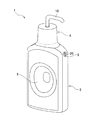
図1は、一実施形態の積層剥離容器1の斜視図である。この図に示されるように、積層剥離容器1は、大きく分けて容器本体2及び蓋体4から構成される。
容器本体2は、上端に口部を、下端に底部を有しており、口部が蓋体4により塞がれることによって積層剥離容器1の密封性が維持される。また、容器本体2の側面には押圧部6、導入弁及び外気導入口20が形成されている。押圧部6は、容器本体2の2つの側面にそれぞれ一対をなして設けられている。積層剥離容器1は、一対の押圧部6を両方向から片手で挟み込まれるようにして把持され、押圧部6が押圧された後にその解除がなされることにより、口部を経由して容器本体2の内部に収容されている内容物を積層剥離容器1の外側に吐出する。なお、押圧部6の押圧及びその解除に伴う導入弁8及び外気導入口20の機構については、詳しく後述する。
FIG. 1 is a perspective view of a
The
蓋体4は、吐出口及び吐出弁(いずれも図1には不図示)を備えている。このうち吐出口は、容器本体2に収容された内容物を吐出するものであり、吐出弁は、吐出口からの内容物の吐出を制御する逆止弁である。そして吐出口は、例えば、その先端に水平方向又は斜め下向きに屈曲したノズルを有している。押圧部6が指で押圧されると、容器本体2の内側に圧力が加わって内容物が口部から押し出されようとするが、口部は蓋体4により塞がれているため、押し出される内容物はまず蓋体4に流れ込む。これに伴い、蓋体4に設けられている吐出弁が開いて内容物が吐出口から、より具体的にはその先端に設けられたノズルを経由して、積層剥離容器1の外側に吐出される。
The lid 4 includes a discharge port and a discharge valve (both not shown in FIG. 1). Among these, the discharge port discharges the contents accommodated in the
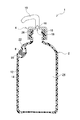
図2は、一実施形態の積層剥離容器1を3方向から見た図を示している。
図2中(A)は積層剥離容器1の正面図である。この図に示されるように、容器本体2の表面上(この図では正面及び背面)には押圧部6が設けられている。押圧部6は、容器本体2の正面(又は背面)から見てすり鉢状に窪んだ形状をなしており、窪みの内縁部分は、その中心に向かって徐々に容器本体2の内側に傾斜するように形成されている。また、窪みの中心部分は平底状となっており、このような形状により押圧部6は、使用者が積層剥離容器1を片手で把持して両方向から押し込む際に、その押し込むべき位置を窪みの中心部分へと案内する(仕向ける)ことができる。そして、案内された位置で容器本体2が撓み切る位置まで押し込まれることにより、積層剥離容器1はその外側に一定量の内容物を吐出することができる。なお、積層剥離容器1が一定量を吐出する機構については、詳しく後述する。
FIG. 2 shows a view of the
2A is a front view of the
図2中(B)は、積層剥離容器1の平面図である。容器本体2には、側面上方に外気導入口20及びこの外気導入口20からの空気の導入を制御する導入弁8が、そして口部を覆うようにして蓋体4が、それぞれ設けられている。蓋体4には、内容物を吐出する吐出口の先端にノズル10を有している。なお、この図において、ノズル10は外気導入口20が形成されている側に向けて正面に水平に設けられているが、この方向に固定はされておらず、左右に回転可能に形成されている。
FIG. 2B is a plan view of the
ここで、ノズル10の先端を略水平又は斜め下向きに屈曲させておくことにより、内容物はノズル10を介して略水平又は斜め下向きに飛び出した直後に、当初の方向よりやや下向きに反れて吐出されることとなる。よって、積層剥離容器1を逆さまにしたり傾けたりすることなく、容器本体2を押圧するだけで内容物を吐出させることが可能となる。
この形態は、例えば洗口剤や液剤タイプの医薬品(風邪薬、うがい薬等)の収容に特に適している。これらの液剤を使用方法として従来は、容器を傾けて計量線が設けられた容器の蓋等に1回分の容量を注いでから口に運ぶ方式が一般的であるが、本実施形態の積層剥離容器1を用いることにより、容器を傾けるステップ及び1回分の容量を計るステップはいずれも不要となり、適量を直接口に注ぐことが可能となる。
Here, by bending the tip of the
This form is particularly suitable for accommodating, for example, a mouthwash or a liquid medicine (cold medicine, mouthwash, etc.). As a method of using these liquid agents, conventionally, a method of inclining the container and pouring a volume for one time into a container lid or the like provided with a measuring line and then carrying it to the mouth is generally used. By using the
図2中(C)は、積層剥離容器1の底面図である。容器本体2は、ブロー成形により形成される。ブロー成形の詳細な工程については後述するが、容器本体2の底部には、ブロー成形の過程で外層12及び内層14同士を加熱融着したのちに周囲に生じるバリ等を取って成形されたピンチオフ部が、正面に水平となる方向に形成されている。
(C) in FIG. 2 is a bottom view of the
図3は、一実施形態の積層剥離容器1を容器本体2の厚み方向の中央で切断した状態を示す縦断面図(図2中(B)のIII−III線に沿う断面図)である。
この図に示されているように、容器本体2は、互いに剥離自在に積層された外層12(外殻)及び内層14(内袋)で形成されている。外層12及び内層14は、互いを剥離自在とするために接着性のない樹脂同士を重ね合わせてブロー成形されている。
FIG. 3 is a longitudinal cross-sectional view (a cross-sectional view taken along line III-III in FIG. 2B) showing a state in which the
As shown in this figure, the
例えば、外層12には、ポリエチレン(PE)、ポリプロピレン(PP)やポリエチレンテレフタレート(PET)の他、エチレン−プロピレン共重合体及びその混合物等が用いられる。外層12は、高い復元性を発揮させるために、内層14よりも肉厚に形成されることが好ましい。また外層12は、単層構成に限定されず複数層構成であってもよい。例えば、容器の成形時に生じたバリをリサイクルして成るリプロ層の両側をPP層で挟んだ構成であってもよい。
本実施形態では、外層12は、プロピレンと別のモノマーとの間のランダム共重合体からなるランダム共重合体層を備える。特定構成のランダム共重合体で構成することにより、外層12の形状復元性・透明性・耐熱性の向上を図ることができる。
For example, the
In the present embodiment, the
また、内層14には、ポリプロピレン(PP)の他、臭気や酸素、水蒸気に対してバリア性を有するポリエチレン(PE)、エチレンビニルアルコール樹脂(EVOH)、環状ポリオレフィン樹脂(COP)等が用いられる。内層14は、複数層構成とすることが好ましい。例えば、内容物に接する最も内側となる面にPE層を配置し、外層に接する最も外側となる面にEVOH層を配置した層構成とする。さらにこれらの層を接着させるために、例えば低密度ポリエチレン(LDPE)又は直鎖状低密度ポリエチレン(LLDPE)と、酸変性ポリエチレンの混合物を用いた接着層を両層の間に配置した層構成としてもよい。EVOH層を設けることにより、内層14のガスバリア性及び外層12からの剥離性を向上させることができる。また、EVOH層に酸素吸収材を含有させることにより、内層14の酸素バリア性を一層高めることが可能である。
In addition to polypropylene (PP), polyethylene (PE), ethylene vinyl alcohol resin (EVOH), cyclic polyolefin resin (COP), etc. having barrier properties against odor, oxygen and water vapor are used for the
ところで、外層12には容器本体2の上方(肩部)に外気導入口20が形成されており、この外気導入口20は導入弁8により塞がれている。外気導入口20は、内層14が外層12から剥離することにより形成される空気室22と容器本体2の外側とを連通して、容器本体2の外側から空気を導入する。導入弁8は、外層12が押圧されて変形する際には空気室22からの空気の流出を阻止する一方で、押圧が解除されて外層12の形状が復元する際には、外部からの空気の流入を許容する役割を担う。
導入弁8は、容器本体2の外側に位置する係止部、空気室22に位置する栓部、そして係止部と栓部とを連結する軸部から構成されている(いずれも参照符号なし)。係止部は、導入弁8が外気導入口20から外れて空気室22内に落ちるのを防止するため、外気導入口20の面積よりも大きく形成されている。また、係止部の内側には溝が形成されている。導入弁8が定位置にあるとき、すなわち外層12が押圧されていない状態では、係止部が外気導入口20を覆うが、係止部の内側に形成された溝により外気導入口20は閉塞されず、空気室22と容器本体2の外側との連通が可能な状態が保たれる。
外層12が押圧されると、加えられた圧力が空気室22の内部に伝わり、内圧が外圧よりも高くなるため、空気室22の空気が容器本体2の外側に流出しようとする。この圧力差と空気の流れに伴い、導入弁8が外側に移動して栓部が外気導入口20を塞ぎ、空気室22からの空気の流出を阻止する。そして、外層12の押圧が解除されると、外層12は自身の弾性により元の形状に復元しようとする。この動きに伴い、導入弁8が内側に移動して定位置に戻り、栓部による外気導入口20の閉塞が解除される。そして、外層12が元の形状に戻るまで、外気導入口20から空気室22に空気が引き込まれる。
By the way, an outside
The
When the
容器本体2の上端部分は口部として形成されており、ここから内容物の充填がなされる。口部の外壁面には、その円周方向に筋状をなして突起したネジ山が形成されている。そして蓋体4の内壁面には、口部のネジ山に対応する凹状の溝(雌ネジ)が形成されている。蓋体4は、ネジ山にガイドされてネジ山と溝が噛み合わさることによって口部にねじ込まれ、容器本体2に固定される。
The upper end portion of the
また、蓋体4には、内面天部のコーナー及び内壁面の溝に沿ってシール部材26が接着されている。これにより、口部に蓋体4をねじ込んだときにシール部材26がネジ山及び谷底に圧着するため、ネジ山及び溝の相互間に生ずる僅かな隙間をも塞ぎ、これらの嵌め合い状態を向上させて、積層剥離容器1がより優れた密封性を発揮することができる。
Further, a sealing
図4は、一実施形態の積層剥離容器1を容器本体2の幅方向の中央で切断した断面を詳細に表した縦断面図(図2中(C)のIV−IV線に沿う断面図)である。このうち図4中(A)は積層剥離容器1が押圧される前の(又は押圧が解除された)状態を、図4中(B)は積層剥離容器1が押圧されている状態を表している。
FIG. 4 is a longitudinal sectional view showing in detail a cross section obtained by cutting the
容器本体2には、互いに対をなす2つの側面に一対の押圧部6が形成されている。押圧部6はその形状に基づき、使用者が積層剥離容器1を片手で把持して両方向から側面を押し込む際に、その押し込むべき位置を案内している。容器本体2は、この位置で外力が付加されたときに所定の形状に変形するが、それ以上には変形しない。具体的には、一対の押圧部6が撓み切って互いに接し合う位置、すなわち、変形量が規制された深さまで押圧されることにより、収容室24から一定の量の内容物を積層剥離容器1の外側へ吐出させることが可能となるよう形成されている。
The container
ここで、一定の量とは、図4中(A)に示されている一対の押圧部6に挟まれた立体的な領域(網掛け部分)を押圧部6の可動範囲として容器本体2が押し潰されることにより、そのとき得られる全体の変形量に応じて容器1から吐出される内容物の体積に相当する。また、容器本体2は、押圧部6が押圧された状態及び押圧が解除された状態において、それぞれ一定の形状が保たれるように形成されている。図4中(B)のように、積層剥離容器1が押圧部6の位置で両側から押圧されると、容器本体2が図中に2点鎖線で示す初期の形状から変形し、内圧が増加する。これにより、吐出弁16が開き、内容物が押し出されて積層剥離容器1の外側に吐出される。
つまり、押圧部6が押圧されていない状態の容器本体2の体積と押圧部6に挟まれた部位が押し潰されて吐出弁16が開いた状態の容器本体2の体積との差分が、積層剥離容器1から吐出する内容物の1回分に相当する体積となるように容器本体2が設計・製作されている。これにより、使用者が単に押圧部6を押圧するだけで一定量の内容物を吐出させることができ、使用する度に計量キャップ等に注いで1回分の適量を計測する手間を省くことが可能となる。
Here, the fixed amount means that the container
That is, the difference between the volume of the container
ところで、蓋体4は上記の吐出口18及び吐出弁16を備えている。押圧部6が押圧されて容器本体2に圧力が加わることにより、容器本体2ひいては内層14が圧縮されると、収容室24(=内層14の内側)に圧力が伝わり吐出弁16が開弁する。そして、収容室24に収容されている内容物が圧力により一定量だけ吐出口18から押し出され、吐出弁16を経由してノズル10から積層剥離容器1の外側に吐出される。
吐出弁16は、収容室24から外側への内容物の流出のみを可能とし、外側から収容室24内への物質の流入を空気も含め全て遮断する。
By the way, the lid body 4 includes the
The
このように、積層剥離容器1は導入弁8及び吐出弁16の2つの弁を有しており、これらは密封性や一定量の吐出という機能を実現する上で重要な役割を果たしている。容器本体2の押圧及びその解除に伴い2つの弁が作動する機構については、詳しく後述する。
As described above, the
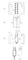
図5は、積層剥離容器1をブロー成形によって製造する工程のうち、材料となる樹脂を金型にセットしてからブロー成型品を金型から取り出すまでの工程を説明する概略図である。なお図5中(A)〜(D)においては、成形過程を理解し易くするため、容器本体2に相当する部分(積層パリソンP及びブロー成型品)のみ断面で表している。
図5中(A):溶融状態の樹脂がダイDから空気中に押し出されて略円筒形状の積層パリソンPを形成する。この積層パリソンPが一対の分割金型Kの間に配置される。
図5中(B):一対の分割金型Kが型締めされることにより、積層パリソンPが分割金型Kで挟み込まれる。そして、ブロー成形後に容器本体2の口部となる側の開口部にブローノズルBを挿入し、分割金型Kのキャビティ内(=分割金型Kにより挟み込まれた積層パリソンPの内側)に加圧エアーを吹き込む。
図5中(C):ブローノズルBを取り外し分割金型Kを開いて、ブロー成型品を取り出す。
図5中(D):取り出したブロー成型品は、のちに容器本体2の底部となる側で分割金型に挟まれた積層パリソンPが加熱融着しピンチオフされている。この段階で、ピンチオフ部より下側に生じた不要なバリ(いわゆる「下バリ」)を除去する。
図5中(D´):下バリを除去したブロー成型品の外観を正面図で表している。この図に示されるように、のちに容器本体2の口部となる部分には未だバリが除去されずに残された状態である。残されたバリは次の工程(予備剥離)で使用するため、この段階では除去されない。
FIG. 5 is a schematic diagram illustrating a process from setting a resin as a material to a mold until a blow molded product is taken out from the mold, among the processes of manufacturing the
In FIG. 5, (A): The molten resin is extruded from the die D into the air to form a substantially cylindrical laminated parison P. The laminated parison P is disposed between a pair of split molds K.
In FIG. 5B, the pair of split molds K are clamped, so that the laminated parison P is sandwiched between the split molds K. Then, the blow nozzle B is inserted into the opening on the side that becomes the mouth of the
In FIG. 5, (C): The blow nozzle B is removed, the split mold K is opened, and the blow molded product is taken out.
In FIG. 5, (D): The blow-molded product taken out is pinched off by heat-sealing the laminated parison P sandwiched between the split molds on the side that becomes the bottom of the
In FIG. 5, (D ′): The appearance of the blow molded product from which the lower burr has been removed is represented by a front view. As shown in this figure, the burr is still left without being removed at the portion that will become the mouth of the
図6は、図5で示した積層剥離容器1の製造工程の続きである外層12及び内層14の予備剥離から導入弁8の装着までを説明する概略図である。
図6中(A):容器本体2の口部上方に残されているバリ部分にブローノズルBを挿入し、外層12と内層14の間に加圧エアーを吹き込んで、外気導入口20が形成され導入弁8が設けられる位置にある内層を外層から剥離させる。このように外層12と内層14とを予備剥離させておくことにより、後続の工程、すなわち外気導入口20を形成し導入弁8を装着する工程を実行し易くなる。
図6中(B):容器本体2の肩部に熱パイプHを押し当てて外層12に穿孔し、外気導入口20を形成する。なお、熱パイプHの代わりに他の穿孔装置、例えばパイプカッター等を用いて穿孔してもよい。
図6中(C):外層12に形成された外気導入口20に導入弁8を装着したのち、口部上方に残されている筒状のバリを除去する。なお、当該工程の順序は入れ替え可能であり、バリの切除を行った後で導入弁8を装着してもよい。
FIG. 6 is a schematic diagram for explaining from the preliminary peeling of the
6A: The blow nozzle B is inserted into the burr portion left above the mouth of the
In FIG. 6 (B): The heat pipe H is pressed against the shoulder of the
6C: After the
図7は、図6で示した積層剥離容器1の製造工程のうち、(A)〜(B)に代替可能な工程を説明する概略図である。
図7中(A1):容器本体2の口部側に吸引装置Sを挿入し、内層14の内側の空気を吸引して内層14の内側を減圧させておく。そしてこれと同時並行して、吸引装置付カッターSCを容器本体2の肩部に近づける。この段階では、外層12と内層14はまだ予備剥離していない。
図7中(A2):容器本体2の肩部に吸引装置付カッターSCを軽く押し当て、小さな孔を形成する。内層12の内側が減圧しているため、吸引装置付カッターSCが外層12を貫通すると、外層14に形成された小さな穴から空気が流入して内層14が外層12から剥離する。このようにして予備剥離がなされる。なお、くり抜かれた切除片は、外層12に穴が形成されると即時に吸引装置付カッターSCにより吸引される。
図7中(B):形成された小さな孔に熱パイプHを押し当ててこの孔を拡径し、外気導入口20を形成する。なお、前工程(A2)において形成した孔が導入弁8を装着する上で十分な径を有しており、既に外気導入口20として機能する場合には、当該工程は不要である。
FIG. 7 is a schematic diagram illustrating steps that can be substituted for (A) to (B) in the manufacturing process of the
In FIG. 7 (A1): The suction device S is inserted into the mouth side of the
In FIG. 7 (A2): The cutter SC with suction device is lightly pressed against the shoulder of the
In FIG. 7B, the heat pipe H is pressed against the formed small hole to expand the diameter of the hole, and the
図8は、積層剥離容器1の押圧及びその解除に伴う空気室22及び内圧の状態を示す図である。なお、ここでは説明の便宜上、押圧部6の図示を省略しているが、実際の形態は図4に示されるとおりである。
〔空気室22に空気が導入され内容物Cが積層剥離容器1から吐出される原理〕
図8中(A):積層剥離容器1は、容器本体2が予め設定した態様に変形するまで押圧部6の位置で押し込まれることにより、収容室24に収容された内容物から一定量を吐出させて使用する容器である(図4)。収容室24(=内層14の内側)は吐出弁16(図8では不図示)により密封されている。この図に示されるように、使用開始前の段階では、内容物Cが殆ど隙間なく収容室24に充填されている。また、導入弁8は外気導入口20の閉塞を解除する定位置に収まっている。
図8中(B):使用開始時は、内容物Cが収容室24にほぼ満杯の状態であり、外層12と内層14は剥離しておらず空気室22が形成されていない。そのため、容器本体2が押圧されると、加えられた圧力が内容物Cに直接伝わり、収容室24が収縮した体積に相当する分の内容物Cがノズル10を介して積層剥離容器1の外側に押し出される。このとき、押圧により加えられた圧力が導入弁8に伝わり、導入弁8が外側に突出する。これにより、導入弁8で外気導入口20が閉塞されるので、外層12及び内層14の間から容器本体2の外側へ空気が流出することはない。
FIG. 8 is a diagram showing the state of the
[Principle in which air is introduced into the
In FIG. 8, (A): The
FIG. 8B: At the start of use, the contents C are almost full in the
図8中(C):容器本体2の押圧が解除されると、収容室24は密封されているため内層12は萎んだままの状態に保たれる一方、外層12が元の形状に復元しようとする作用(内圧の低下)で導入弁8が移動することにより外気導入口20の閉塞が解除され、ここから空気が取り入れられる。これにより、内層14が外層12から剥離し、空気室22が形成される。外層12が元の形状に復元するまで空気が引き込まれると、導入弁8が空気の流れと共に移動して内側の定位置に復帰する。
図8中(D)及び(E):2回目以降の使用時には、既に外層12と内層14との間に空気室22が形成されている。容器本体2の押圧及びその解除を繰り返されることにより、前述の導入弁8の働きによって収容室24から内容物Cが吐出された分だけ空気室22の体積が拡張していく。
図8中(F):空気室22が形成された状態で容器本体2が押圧されると、外層12に加えられた圧力が空気室22に伝わり、さらに空気室22の内圧が内層14の表面に加わることによって、収容室24が収縮する。そして、収容室24が収縮した体積に相当する内容物Cが積層剥離容器1の外側に押し出され吐出される。この場合でも、容器本体2の変形量に応じた体積分だけ内層14が収縮するので、内容物Cの残量にかかわらず、容器本体2の変形量が一定であれば内容物Cの吐出量も一定となる。
FIG. 8C: When the
(D) and (E) in FIG. 8: The
8F: When the
このようにして、空気室22が形成された後は、容器本体2の押圧により収容室24が収縮して内容物Cが積層剥離容器1の外側に吐出され、押圧の解除により空気室22の体積が吐出された内容物Cの相当分ずつ拡張していく。収容室24に収容された内容物Cがすべて吐出されるまで、容器本体2の押圧及びその解除が繰り返される。
そしてこの間、上記のように容器本体2の変形量は押圧部6によって毎回ほぼ一定に保たれているので(図4)、毎回の使用時における内容物Cの吐出量を概ね一定に設定することができる。
After the
During this time, as described above, the deformation amount of the
なお、本発明は上述した実施形態に限定されることなく、種々に変形して実施することが可能である。
例えば、上述の実施形態においては、外気導入口20を容器本体2の肩部に形成し、ここに導入弁8を装着したが、この配置は、積層剥離容器1を使用する際に操作の邪魔にならない部位として選択されたものである。したがって、これらを容器本体2の正面上方あるいは底部に設けてもよい。そして導入弁8の係止部の内側には溝を設けたが、外気導入口20を閉塞しない構造が実現できれば、溝に限定される必要はなく、例えば溝の代わりに突起を設けてもよい。尚、押圧開始時における、外気導入口からの空気漏れをなくすため、導入弁は、押圧前から外気導入口を完全に閉じている弁とすることが好ましい。例えば、導入弁が外気導入口を閉じる方向に所定の力(容器復元時に導入弁が開く程度の微小な力)で押しこまれている構成とすることが好ましい。また、予め外気導入口を閉じた状態となるようにフィルムが配置され、外気導入口を介して内部空間から外部に空気が流出することを阻止する一方、外気導入口を介して内部空間に空気が流入することをフィルムの変形により許容するフィルム状逆止弁を用いてもよい。これにより、より正確な定量吐出ができる。
The present invention is not limited to the above-described embodiment, and can be implemented with various modifications.
For example, in the above-described embodiment, the outside
また、吐出口18は先端が略水平又は斜め下向きに屈曲したノズル10を有するものとしたが、このノズル10を覆って保護するヒンジキャップをさらに設けてもよい。
さらに、容器本体2を外層12と内層14とを積層パリソンのブロー成形により形成したが、外層12と内層14とを個別に形成したのちに外層12の内側に内層14を組み込んで形成することもできる。
The
Furthermore, although the
一実施形態では、押圧部6をすり鉢状の窪み形状としているが、押圧部6は球面状であってもよいし、多面形状であってもよい。また、押圧部6を形成する位置や個数は適宜に変更が可能である。例えば、1つの容器本体2に複数個の押圧部6を形成し、その位置(上・中・下)によって押し込みによる変形量を段階的に異ならせることで、毎回の吐出量を複数段階(多量・中間量・少量)に変化させることもできる。
In one embodiment, although the
1 積層剥離容器
2 容器本体
4 蓋体
6 押圧部
8 導入弁
10 ノズル
12 外層
14 内層
16 吐出弁
18 吐出口
20 外気導入口
22 空気室(内部空間)
24 収容室
26 シール部材
DESCRIPTION OF
24
Claims (5)
前記外層に形成され、前記内層と前記外層との間に生じる内部空間に空気を導入させる外気導入口と、
前記外気導入口を介して前記内部空間から外部に空気が流出することを阻止する一方、前記外気導入口を介して前記内部空間に空気が流入することを許容する導入弁と、
前記容器本体に収容された内容物を吐出する吐出口と、
前記吐出口から内容物が流出することを許容する一方で前記吐出口から容器内に外気が流入することを阻止する吐出弁と、
前記外層に形成され、外力の付加に伴う前記外層の変形を予め設定した態様に規制する押圧部と
を備えた容器。 A container body composed of an outer layer that is deformed by receiving external force and can be restored to the shape of a container with the removal of the external force, and an inner layer that forms a bag for containing contents,
An outside air inlet that is formed in the outer layer and that introduces air into an inner space formed between the inner layer and the outer layer;
An introduction valve that prevents air from flowing out from the internal space through the outside air introduction port while allowing air to flow into the internal space through the outside air introduction port;
A discharge port for discharging the contents contained in the container body;
A discharge valve that allows the contents to flow out of the discharge port while preventing the outside air from flowing into the container from the discharge port;
A container provided with a pressing portion that is formed on the outer layer and restricts deformation of the outer layer in accordance with the application of an external force to a preset mode.
前記押圧部は、
互いに対をなす前記容器本体の2つの側面のそれぞれに一対をなして設けられており、使用者が前記容器本体を片手で把持した状態で前記一対の押圧部を両方向から押し込み可能な位置に設けられることを特徴とする容器。 The container according to claim 1,
The pressing portion is
A pair is provided on each of the two side surfaces of the container body that are paired with each other, and the pair of pressing portions are provided at positions where the user can push in from both directions while holding the container body with one hand. A container characterized by being made.
前記吐出口は、先端が略水平又は斜め下向きに屈曲したノズルを有することを特徴とする容器。 The container according to claim 1 or 2,
The discharge port has a nozzle whose tip is bent substantially horizontally or obliquely downward.
前記外気導入口は、前記容器本体の側面であって前記押圧部より上方の位置に設けられることを特徴とする容器。 In the container according to any one of claims 1 to 3,
The said outside air inlet is a side surface of the said container main body, Comprising: The container characterized by the above-mentioned.
前記外気導入口は、前記容器本体の底部に設けられることを特徴とする容器。 In the container according to any one of claims 1 to 3,
The said outside air inlet is provided in the bottom part of the said container main body, The container characterized by the above-mentioned.
Priority Applications (1)
| Application Number | Priority Date | Filing Date | Title |
|---|---|---|---|
| JP2014113977A JP6547242B2 (en) | 2014-06-02 | 2014-06-02 | container |
Applications Claiming Priority (1)
| Application Number | Priority Date | Filing Date | Title |
|---|---|---|---|
| JP2014113977A JP6547242B2 (en) | 2014-06-02 | 2014-06-02 | container |
Publications (2)
| Publication Number | Publication Date |
|---|---|
| JP2015227203A true JP2015227203A (en) | 2015-12-17 |
| JP6547242B2 JP6547242B2 (en) | 2019-07-24 |
Family
ID=54884952
Family Applications (1)
| Application Number | Title | Priority Date | Filing Date |
|---|---|---|---|
| JP2014113977A Active JP6547242B2 (en) | 2014-06-02 | 2014-06-02 | container |
Country Status (1)
| Country | Link |
|---|---|
| JP (1) | JP6547242B2 (en) |
Cited By (8)
| Publication number | Priority date | Publication date | Assignee | Title |
|---|---|---|---|---|
| WO2017179529A1 (en) * | 2016-04-15 | 2017-10-19 | キョーラク株式会社 | Separable laminate container |
| WO2017183502A1 (en) * | 2016-04-18 | 2017-10-26 | キョーラク株式会社 | Peelable laminated container |
| JP2017193342A (en) * | 2016-04-18 | 2017-10-26 | キョーラク株式会社 | Delamination container |
| JP2017218168A (en) * | 2016-06-03 | 2017-12-14 | キョーラク株式会社 | Delamination container |
| JP2019026350A (en) * | 2017-07-31 | 2019-02-21 | キョーラク株式会社 | Double container |
| JP2019147603A (en) * | 2018-02-28 | 2019-09-05 | 株式会社吉野工業所 | Squeeze exhalation container |
| JP2019531983A (en) * | 2016-09-26 | 2019-11-07 | ベーリンガー インゲルハイム インターナショナル ゲゼルシャフト ミット ベシュレンクテル ハフツング | Method for forming and / or testing a bag in the interior space of a container |
| JP2020093817A (en) * | 2018-12-13 | 2020-06-18 | キョーラク株式会社 | Delamination container |
Citations (16)
| Publication number | Priority date | Publication date | Assignee | Title |
|---|---|---|---|---|
| JPS4816226B1 (en) * | 1970-10-02 | 1973-05-21 | ||
| JPS49144646U (en) * | 1973-04-10 | 1974-12-13 | ||
| JPS54180057U (en) * | 1978-06-05 | 1979-12-19 | ||
| US4349134A (en) * | 1980-09-09 | 1982-09-14 | Ahk Alkohol Handelskontor Gmbh | Valved, resilient-walled container for safely dispensing flammable liquids |
| JPH03111258A (en) * | 1989-09-26 | 1991-05-13 | Midori Itou | Packaging container |
| JPH03133748A (en) * | 1989-10-13 | 1991-06-06 | Riyouichi Kitase | Container having pour spout |
| JPH0577345A (en) * | 1991-08-05 | 1993-03-30 | Yoshino Kogyosho Co Ltd | Laminated bottle |
| US5454486A (en) * | 1992-09-28 | 1995-10-03 | Colgate-Palmolive Co. | Squeezable dispension container for fluid materials |
| JPH09328177A (en) * | 1996-06-10 | 1997-12-22 | Yoshino Kogyosho Co Ltd | Pumping device for container |
| JP2003104416A (en) * | 2001-09-28 | 2003-04-09 | Yoshino Kogyosho Co Ltd | Pour-out container for viscous liquid |
| JP3496456B2 (en) * | 1997-05-22 | 2004-02-09 | 東洋製罐株式会社 | Ejector head of pump dispenser |
| JP2004210345A (en) * | 2002-12-27 | 2004-07-29 | Yoshino Kogyosho Co Ltd | Spout container |
| JP2009512490A (en) * | 2005-10-26 | 2009-03-26 | ザ プロクター アンド ギャンブル カンパニー | Liquid sprayer |
| JP2011031921A (en) * | 2009-07-31 | 2011-02-17 | Yoshino Kogyosho Co Ltd | Spouting cap for double container, and double container having the spouting cap |
| US20120157307A1 (en) * | 2010-12-19 | 2012-06-21 | John Karl Lampe | Foamable Solutions, Dispenser, and Methods |
| US20140110438A1 (en) * | 2011-08-01 | 2014-04-24 | Kathryn Madison | Hair color bottle |
-
2014
- 2014-06-02 JP JP2014113977A patent/JP6547242B2/en active Active
Patent Citations (16)
| Publication number | Priority date | Publication date | Assignee | Title |
|---|---|---|---|---|
| JPS4816226B1 (en) * | 1970-10-02 | 1973-05-21 | ||
| JPS49144646U (en) * | 1973-04-10 | 1974-12-13 | ||
| JPS54180057U (en) * | 1978-06-05 | 1979-12-19 | ||
| US4349134A (en) * | 1980-09-09 | 1982-09-14 | Ahk Alkohol Handelskontor Gmbh | Valved, resilient-walled container for safely dispensing flammable liquids |
| JPH03111258A (en) * | 1989-09-26 | 1991-05-13 | Midori Itou | Packaging container |
| JPH03133748A (en) * | 1989-10-13 | 1991-06-06 | Riyouichi Kitase | Container having pour spout |
| JPH0577345A (en) * | 1991-08-05 | 1993-03-30 | Yoshino Kogyosho Co Ltd | Laminated bottle |
| US5454486A (en) * | 1992-09-28 | 1995-10-03 | Colgate-Palmolive Co. | Squeezable dispension container for fluid materials |
| JPH09328177A (en) * | 1996-06-10 | 1997-12-22 | Yoshino Kogyosho Co Ltd | Pumping device for container |
| JP3496456B2 (en) * | 1997-05-22 | 2004-02-09 | 東洋製罐株式会社 | Ejector head of pump dispenser |
| JP2003104416A (en) * | 2001-09-28 | 2003-04-09 | Yoshino Kogyosho Co Ltd | Pour-out container for viscous liquid |
| JP2004210345A (en) * | 2002-12-27 | 2004-07-29 | Yoshino Kogyosho Co Ltd | Spout container |
| JP2009512490A (en) * | 2005-10-26 | 2009-03-26 | ザ プロクター アンド ギャンブル カンパニー | Liquid sprayer |
| JP2011031921A (en) * | 2009-07-31 | 2011-02-17 | Yoshino Kogyosho Co Ltd | Spouting cap for double container, and double container having the spouting cap |
| US20120157307A1 (en) * | 2010-12-19 | 2012-06-21 | John Karl Lampe | Foamable Solutions, Dispenser, and Methods |
| US20140110438A1 (en) * | 2011-08-01 | 2014-04-24 | Kathryn Madison | Hair color bottle |
Cited By (18)
| Publication number | Priority date | Publication date | Assignee | Title |
|---|---|---|---|---|
| KR102357828B1 (en) | 2016-04-15 | 2022-01-28 | 교라꾸 가부시끼가이샤 | delaminate container |
| WO2017179529A1 (en) * | 2016-04-15 | 2017-10-19 | キョーラク株式会社 | Separable laminate container |
| CN114834719A (en) * | 2016-04-15 | 2022-08-02 | 京洛株式会社 | Laminated peeling container |
| US10752395B2 (en) | 2016-04-15 | 2020-08-25 | Kyoraku Co., Ltd. | Delaminatable container |
| KR20180129940A (en) * | 2016-04-15 | 2018-12-05 | 교라꾸 가부시끼가이샤 | Lamination peeling container |
| CN109071059A (en) * | 2016-04-15 | 2018-12-21 | 京洛株式会社 | Peel container is laminated |
| CN114834720A (en) * | 2016-04-15 | 2022-08-02 | 京洛株式会社 | Laminated peeling container |
| JP2017193342A (en) * | 2016-04-18 | 2017-10-26 | キョーラク株式会社 | Delamination container |
| WO2017183502A1 (en) * | 2016-04-18 | 2017-10-26 | キョーラク株式会社 | Peelable laminated container |
| JP6993554B2 (en) | 2016-04-18 | 2022-01-13 | キョーラク株式会社 | Laminated peeling container |
| JP2017218168A (en) * | 2016-06-03 | 2017-12-14 | キョーラク株式会社 | Delamination container |
| JP7183152B2 (en) | 2016-09-26 | 2022-12-05 | ベーリンガー インゲルハイム インターナショナル ゲゼルシャフト ミット ベシュレンクテル ハフツング | Method for forming and/or testing a bag in the interior space of a container |
| JP2019531983A (en) * | 2016-09-26 | 2019-11-07 | ベーリンガー インゲルハイム インターナショナル ゲゼルシャフト ミット ベシュレンクテル ハフツング | Method for forming and / or testing a bag in the interior space of a container |
| JP7104875B2 (en) | 2017-07-31 | 2022-07-22 | キョーラク株式会社 | double container |
| JP2019026350A (en) * | 2017-07-31 | 2019-02-21 | キョーラク株式会社 | Double container |
| JP2019147603A (en) * | 2018-02-28 | 2019-09-05 | 株式会社吉野工業所 | Squeeze exhalation container |
| JP7244740B2 (en) | 2018-12-13 | 2023-03-23 | キョーラク株式会社 | delaminating container |
| JP2020093817A (en) * | 2018-12-13 | 2020-06-18 | キョーラク株式会社 | Delamination container |
Also Published As
| Publication number | Publication date |
|---|---|
| JP6547242B2 (en) | 2019-07-24 |
Similar Documents
| Publication | Publication Date | Title |
|---|---|---|
| JP2015227203A (en) | container | |
| WO2017094880A1 (en) | Lamination separable container | |
| TWI766934B (en) | Laminated peel container | |
| JP6421458B2 (en) | Delamination container | |
| WO2016027732A1 (en) | Double-walled container manufacturing method | |
| JP6451087B2 (en) | Delamination container | |
| JP6025040B2 (en) | Blow molding container and blow molding method | |
| JP6366518B2 (en) | Squeeze foamer container | |
| JP4834260B2 (en) | Liquid storage container and method for manufacturing the container | |
| JP6775132B2 (en) | Double container | |
| WO2017142027A1 (en) | Double-layered container and method for production of same | |
| JP7258429B2 (en) | double container | |
| JP6451075B2 (en) | Delamination container | |
| JP2018052578A (en) | Multilayer container, and method for separating outer layer portion and inner layer portion thereof | |
| JP2020023352A (en) | Double container | |
| JP6858450B2 (en) | Method for manufacturing synthetic resin blow-molded containers and containers with contents | |
| KR200482051Y1 (en) | Plastic dual container | |
| JP7285432B2 (en) | double container | |
| JP7317450B2 (en) | double container | |
| JP2019099212A (en) | Layered peeling container | |
| JP7431106B2 (en) | double container | |
| JP2017214100A (en) | Molded product and production method and production device therefor | |
| JP2022127527A (en) | double container | |
| JP2017081643A (en) | Delamination container | |
| WO2017073606A1 (en) | Double container and manufacturing method for same |
Legal Events
| Date | Code | Title | Description |
|---|---|---|---|
| A621 | Written request for application examination |
Free format text: JAPANESE INTERMEDIATE CODE: A621 Effective date: 20170331 |
|
| A977 | Report on retrieval |
Free format text: JAPANESE INTERMEDIATE CODE: A971007 Effective date: 20171120 |
|
| A131 | Notification of reasons for refusal |
Free format text: JAPANESE INTERMEDIATE CODE: A131 Effective date: 20171219 |
|
| A521 | Request for written amendment filed |
Free format text: JAPANESE INTERMEDIATE CODE: A523 Effective date: 20180130 |
|
| A131 | Notification of reasons for refusal |
Free format text: JAPANESE INTERMEDIATE CODE: A131 Effective date: 20180612 |
|
| A521 | Request for written amendment filed |
Free format text: JAPANESE INTERMEDIATE CODE: A523 Effective date: 20180626 |
|
| A131 | Notification of reasons for refusal |
Free format text: JAPANESE INTERMEDIATE CODE: A131 Effective date: 20181127 |
|
| A521 | Request for written amendment filed |
Free format text: JAPANESE INTERMEDIATE CODE: A523 Effective date: 20181212 |
|
| TRDD | Decision of grant or rejection written | ||
| A01 | Written decision to grant a patent or to grant a registration (utility model) |
Free format text: JAPANESE INTERMEDIATE CODE: A01 Effective date: 20190528 |
|
| A61 | First payment of annual fees (during grant procedure) |
Free format text: JAPANESE INTERMEDIATE CODE: A61 Effective date: 20190610 |
|
| R150 | Certificate of patent or registration of utility model |
Ref document number: 6547242 Country of ref document: JP Free format text: JAPANESE INTERMEDIATE CODE: R150 |
|
| R250 | Receipt of annual fees |
Free format text: JAPANESE INTERMEDIATE CODE: R250 |