JP2019147603A - Squeeze exhalation container - Google Patents
Squeeze exhalation container Download PDFInfo
- Publication number
- JP2019147603A JP2019147603A JP2018034736A JP2018034736A JP2019147603A JP 2019147603 A JP2019147603 A JP 2019147603A JP 2018034736 A JP2018034736 A JP 2018034736A JP 2018034736 A JP2018034736 A JP 2018034736A JP 2019147603 A JP2019147603 A JP 2019147603A
- Authority
- JP
- Japan
- Prior art keywords
- container
- squeeze
- mouth
- discharge
- regulating members
- Prior art date
- Legal status (The legal status is an assumption and is not a legal conclusion. Google has not performed a legal analysis and makes no representation as to the accuracy of the status listed.)
- Granted
Links
Images


Abstract
Description
本発明は、スクイズ吐出容器に関する。 The present invention relates to a squeeze discharge container.
口部、胴部及び底部を有するとともに内容物を収容可能なボトル形状の容器本体と、口部に取り付けられるとともに内容物の吐出口を有するキャップと、を備え、胴部をスクイズ(押圧)することで内容物を吐出口から吐出可能なスクイズ吐出容器が知られている。このようなスクイズ吐出容器は、スクイズによる内容物の定量吐出を可能にするための規制部材を備えることがある。例えば特許文献1に記載される規制部材は、口部の内側においてキャップに固定された上端を有する筒状をなしており、当該上端から容器本体の底部に向かって延在している。そして、胴部をスクイズして内側に変形させると、変形した胴部が規制部材に当接する。この当接により、胴部の変形量が規制されて、内容物の定量吐出が可能となる。
A bottle-shaped container main body having a mouth part, a body part, and a bottom part and capable of containing contents, and a cap attached to the mouth part and having a discharge outlet for contents, and squeeze (press) the body part Thus, there is known a squeeze discharge container capable of discharging contents from a discharge port. Such a squeeze discharge container may be provided with a regulating member for enabling quantitative discharge of contents by squeeze. For example, the regulating member described in
しかし、特許文献1に記載されるような規制部材を備えるスクイズ吐出容器は、規制部材を口部の内側に配置するために、容器本体の形状が、口部の径が大きい広口ボトル形状に制限される傾向があった。
However, in a squeeze discharge container including a regulating member as described in
本発明は、このような問題に鑑み、内容物の定量吐出が可能で容器形状の自由度の高いスクイズ吐出容器を提供することを目的とする。 In view of such a problem, an object of the present invention is to provide a squeeze discharge container capable of quantitative discharge of contents and having a high degree of freedom in container shape.
本発明の一態様に係るスクイズ吐出容器は、
筒状の口部と前記口部に連なるとともにスクイズによって内側に変形可能な胴部とを有する外容器と、
前記外容器の内側に配置されるとともに内容物の収容空間を区画する内容器と、
前記口部に取り付けられるとともに前記内容物の吐出口を有するキャップと、
前記胴部に取り付けられる規制部材と、を備え、
前記規制部材は、前記胴部に設けた貫通口を通して前記胴部の内側に延在する延在部を有するとともに、前記延在部により、スクイズによる前記胴部の変形量を規制可能である。
The squeeze discharge container according to one aspect of the present invention is
An outer container having a cylindrical mouth portion and a trunk portion that is continuous with the mouth portion and can be deformed inward by squeeze;
An inner container that is disposed inside the outer container and divides a content storage space;
A cap attached to the mouth and having an outlet for the contents;
A restricting member attached to the body,
The restricting member has an extending portion that extends to the inside of the trunk portion through a through hole provided in the trunk portion, and the extension portion can regulate the deformation amount of the trunk portion due to squeeze.
本発明に係るスクイズ吐出容器は、
一組の前記規制部材を有してもよく、
前記一組の規制部材の前記延在部が、スクイズによる前記胴部の変形により、前記内容器を挟んで互いに突き当たることで前記胴部の変形量を規制可能であってもよい。
The squeeze discharge container according to the present invention,
It may have a set of the regulating members,
The extension of the pair of regulating members may be able to regulate the amount of deformation of the body by abutting each other across the inner container by deformation of the body by squeezing.
本発明に係るスクイズ吐出容器は、前記一組の規制部材が、互いに同一の形状及び大きさを有してもよい。 In the squeeze discharge container according to the present invention, the set of regulating members may have the same shape and size.
本発明に係るスクイズ吐出容器は、
複数の前記規制部材を有してもよく、
前記複数の規制部材の前記延在部が、スクイズによる前記胴部の変形量を、互いに異なる変形量に規制可能であってもよい。
The squeeze discharge container according to the present invention,
It may have a plurality of the regulating members,
The extending portions of the plurality of restricting members may be capable of restricting deformation amounts of the body portion due to squeeze to different deformation amounts.
本発明に係るスクイズ吐出容器は、前記キャップが、前記収容空間の正圧化によって前記吐出口を開放する一方、前記収容空間の負圧化によっても前記吐出口を開放する弁体を有してもよい。 In the squeeze discharge container according to the present invention, the cap has a valve body that opens the discharge port by positive pressure of the storage space, and opens the discharge port by negative pressure of the storage space. Also good.
本発明に係るスクイズ吐出容器は、前記弁体が、前記吐出口としてのスリットを有するスリット弁によって構成されていてもよい。 In the squeeze discharge container according to the present invention, the valve body may be constituted by a slit valve having a slit as the discharge port.
本発明に係るスクイズ吐出容器は、
前記外容器が、積層剥離容器の外層体によって構成されていてもよく、
前記内容器が、前記積層剥離容器の内層体によって構成されていてもよい。
The squeeze discharge container according to the present invention,
The outer container may be constituted by an outer layer body of a delamination container,
The inner container may be constituted by an inner layer body of the delamination container.
本発明に係るスクイズ吐出容器は、
前記口部が、前記口部を径方向に貫通する通気口を有してもよく、
前記キャップが、前記口部に取り付けられることによって前記通気口と外部との連通を遮断してもよい。
The squeeze discharge container according to the present invention,
The mouth portion may have a vent hole that penetrates the mouth portion in a radial direction,
The cap may block communication between the vent and the outside by being attached to the mouth.
本発明によれば、内容物の定量吐出が可能で容器形状の自由度の高いスクイズ吐出容器を提供することができる。 According to the present invention, it is possible to provide a squeeze discharge container capable of quantitative discharge of contents and having a high degree of freedom in container shape.
以下、図面を参照して、本発明の実施形態に係るスクイズ吐出容器1について詳細に例示説明する。なお、本明細書において、上下方向とは、外容器2の口部2aの中心軸線Oに沿う方向を意味する。また、上方とは、底部2cから口部2aに向かう方向を意味し、下方とは、その反対方向を意味する。また、縦断面とは、口部2aの中心軸線Oを含む断面を意味し、横断面とは、口部2aの中心軸線Oと垂直な断面を意味する。
Hereinafter, the
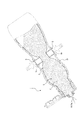
図1に示すように、本実施形態に係るスクイズ吐出容器1は、外容器2、内容器3、キャップ4及び一組の規制部材5を備えている。
As shown in FIG. 1, the
外容器2は、中心軸線Oを中心とする略円筒形状の口部2aと、口部2aに連なるとともにスクイズによって内側に変形可能な胴部2bと、胴部2bの下端を閉塞する底部2cと、を有している。口部2aは、下側部分が拡径した2段円筒形状をなしている。口部2aにおける上側部分の外周面には、キャップ4を取付けるための雄ねじ部6が設けられている。しかし、このような雄ねじ部6による取り付けに替えて、凹凸形状の嵌合による取り付けを可能にする構成を採用してもよい。口部2aにおける上側部分には、口部2aを径方向に貫通する通気口7が設けられている。本実施形態では、通気口7は2つ設けられているが、その数は適宜増減が可能である。口部2aの下側部分の外周面には、ネックリング8が設けられている。しかし、ネックリング8を設けない構成としてもよい。胴部2bは、上下方向の全体に亘って横断面が楕円形状をなしている。また、胴部2bにおける上部は、口部2aの下端から下方に向けて漸次拡径しており、胴部2bにおける上下方向中間部は、上下方向で径の変化がなく、胴部2bにおける下部は、下方に向けて漸次縮径している。
The outer container 2 includes a substantially
内容器3は、外容器2の内側に配置されるとともに内容物Cの収容空間Sを区画している。
The
本実施形態では、外容器2は、デラミネーション容器(デラミ容器)とも称される積層剥離容器の外層体によって構成されており、内容器3は、積層剥離容器の内層体によって構成されている。このような積層剥離容器は、例えば、押出しブロー成形(EBM:Extrusion Blow Molding)によって形成することができる。この場合、先ず、相溶性の低い外層体用の合成樹脂材料と内層体用の合成樹脂材料とを共押出して積層パリソンを形成し、この積層パリソンを、金型を用いてブロー成形することにより、外層体の内面に内層体が剥離可能に密着した積層構造の容器を形成することができる。押出しブロー成形の後、口部2aに通気口7を形成し、口部2aの上端開口(上端縁によって形成された開口)からの吸引等により内層体を一度収縮させて、内層体の略全体を外層体から剥離させることができる。次いで、胴部2bに一組の貫通口9を形成し、当該一組の貫通口9にそれぞれ規制部材5を取り付けることができる。その後、内層体の内部(収容空間S)に空気を送り込むこと等により内層体の形状を復元させることができる。なお、一組の貫通口9は、通気口7の形成と同時に形成してもよい。また、口部2aに通気口7を設けずに、一組の貫通口9を形成した後、一組の貫通口9の近傍のみにおいて内層体を外層体から剥離させることによって外容器2及び内容器3を構成してもよい。
In the present embodiment, the outer container 2 is configured by an outer layer body of a delamination container (also referred to as a delamination container), and the
積層剥離容器は、有底筒状のプリフォームを対象とする2軸延伸ブロー成形によって構成してもよい。この場合、プリフォームは、外層体を形成する外側層と内層体を形成する内側層とからなる積層プリフォームであってもよい。また、プリフォームは、外層体を形成する外体と、内層体を形成する内体とを互いに組み付けて構成される2重プリフォームであってもよい。 The delamination container may be configured by biaxial stretch blow molding for a bottomed cylindrical preform. In this case, the preform may be a laminated preform including an outer layer that forms the outer layer body and an inner layer that forms the inner layer body. Further, the preform may be a double preform configured by assembling an outer body that forms the outer layer body and an inner body that forms the inner layer body.
外容器2及び内容器3は、積層剥離容器によって構成しないこともできる。例えば、外容器2及び内容器3は、別個に形成された後に、互いに組み付けられることによって構成されてもよい。
The outer container 2 and the
胴部2bの上下方向中間部には、その楕円形状の横断面における短軸上に一組の貫通口9が設けられている。一組の貫通口9には、それぞれ規制部材5が取り付けられており、これらで一組の規制部材5を構成している。一組の規制部材5は、本実施形態では、互いに同一の形状及び大きさを有している。また、一組の貫通口9も、本実施形態では、互いに同一の形状及び大きさを有している。一組の貫通口9の各々は、円形状をなしている。一組の規制部材5の各々は、貫通口9を通して胴部2bの内側に延在する延在部5aと、胴部2bの外面に沿って配置される板状部5bと、を有している。延在部5aは、円筒形状をなす中空ロッド状に形成されている。板状部5bは、貫通口9より大きい直径を有する円板状に形成されている。板状部5bの中央は胴部2bの内側に向けてやや窪んでおり、使用者が胴部2bをスクイズする際に指の腹にフィットするようになっている。すなわち、板状部5bはスクイズ時の操作部となっている。板状部5bが貫通口9より胴部2bの外側に位置することにより、規制部材5が胴部2bの内側に抜け落ちることが防止されている。また、延在部5aの外周面には、胴部2bの内周面と係合する円環形状の係合凸部5cが設けられている。係合凸部5cが胴部2bの内周面と係合することにより、規制部材5が胴部2bの外側に抜け落ちることが防止されている。貫通口9は、スクイズ時の操作感を向上する(スクイズによる圧力の抜けを防止する)観点から、規制部材5によって封止されていることが好ましい。しかし、貫通口9が規制部材5によって完全に封止されていなかったとしても、内容物は内容器3に収容されているので、貫通口9から内容物が漏れ出ることはない。
A pair of through-
キャップ4は、口部2aに取り付けられるとともに内容物Cの吐出口4aを有している。本実施形態では、キャップ4は、ベース4b、蓋4c、弁体4d及び弁押え部材4eを有している。蓋4cは、ヒンジ4fを介してベース4bに連結している。しかし、蓋4cをベース4bに着脱可能に構成してもよい。ベース4bは、口部2aの雄ねじ部6と螺合する雌ねじ部10を有する装着筒11を有している。装着筒11の上端には、径方向内側に延在する天壁12が連結しており、天壁12は、口部2aの上端に全周に亘って密着している。また、装着筒11における下部は、口部2aにおける下側部分の外周面に全周に亘って密着している。したがって、キャップ4は、口部2aに取り付けられることによって通気口7と外部との連通を遮断している。このように通気口7と外部との連通を遮断することにより、スクイズ時の操作感を向上できるとともに、内容物の吐出後に外部から空気が通気口7を通して外容器2と内容器3との間に流入することが防止される。
The cap 4 is attached to the
天壁12の下面には、中心軸線Oを中心とする円環形状をなすとともに上下方向に連なる2段階の段部、すなわち下段部12a及び上段部12bが設けられている。また、上段部12bの上方には、中心軸線Oを中心とする円形状の開口12cが設けられている。弁体4dは、下段部12aに嵌合によって取り付けられた弁押え部材4eにより、上段部12bに固定されている。弁体4dは、上段部12bに配置された円環形状をなす外縁部13と、外縁部13の内周縁から上方に延在する切頭円錐形状の周壁14と、周壁14の上端に連結するとともに下向き球面形状をなす隔壁15と、を有している。周壁14及び隔壁15は、天壁12の開口12cの径方向内側に位置している。弁押え部材4eは、下段部12aに配置された円環形状の平板状をなす環状板16と、環状板16の内周縁から上方に延在する切頭円錐形状の環状凸部17と、を有している。環状凸部17は、弁体4dの外縁部13より径方向内側に位置している。
The lower surface of the
弁体4dは、吐出口4aとしてのスリット18を有するスリット弁によって構成されている。なお、スリット18は平面視で十文字形状をなしているが、その形状は適宜変更が可能である。例えば、スリット18は平面視で一文字形状又はY字形状等をなしていてもよい。また、弁体4dは、収容空間Sの正圧化によって吐出口4aを開放する一方、収容空間Sの負圧化によっても吐出口4aを開放するように構成されている。
4 d of valve bodies are comprised by the slit valve which has the
スクイズ吐出容器1は、例えば以下の要領によって使用することができる。まず、使用者は、図2に示すように、蓋4cを開き、外容器2を傾倒させる。このとき、弁体4dのスリット18は閉塞しており、内容物Cは吐出口4aから吐出されない。
The
次いで、図3に示すように、使用者は、一組の規制部材5の板状部5b(操作部)上を指で摘み、胴部2bをスクイズする。このスクイズにより、胴部2bが内側に変形して、その内側に位置する内容器3も内側に押されて収容空間Sが正圧化し、スリット18(吐出口4a)が開放されて内容物Cが吐出される。
Next, as shown in FIG. 3, the user picks up the plate-
そして、さらなるスクイズによって胴部2bの変形が進行していくと、最終的に、図4に示されるように、一組の規制部材5の延在部5aの先端が内容器3を挟んで互いに突き当たり、それ以上の胴部2bの変形が規制される。このように、一組の規制部材5の延在部5aは、スクイズによる胴部2bの変形により、内容器3を挟んで互いに突き当たることで胴部2bの変形量を規制可能である。したがって、本実施形態に係るスクイズ吐出容器1によれば、比較的大量の定量化された内容物Cを、簡便な操作で吐出可能である。
Then, when the deformation of the
その後、スクイズを解除すると、胴部2bが復元し、その復元に伴って内容器3も復元し、収容空間Sが負圧化する。この負圧化により、スリット18(吐出口4a)が開放されて、内容物Cの吐出量に対応する量の空気が外部から収容空間Sに流入する。このように、吐出された内容物Cが空気に置換される。
Thereafter, when the squeeze is released, the
前述した本実施形態は、本発明の実施形態の一例にすぎず、発明の要旨を逸脱しない範囲で種々変更可能であることはいうまでもない。 The above-described embodiment is merely an example of the embodiment of the present invention, and it is needless to say that various modifications can be made without departing from the gist of the invention.
例えば、一組の規制部材5は、前記の実施形態では互いに同一の形状及び大きさを有しているが、このような構成に限られない。例えば、一組の規制部材5は、一方の延在部5aが他方の延在部5aよりも長く形成されていてもよい。また、スクイズ吐出容器1は、前記の実施形態では一組のみの規制部材5を有しているが、複数組の規制部材5を有していてもよい。また、複数組の規制部材5の延在部5aは、スクイズによる胴部2bの変形量を、互いに異なる変形量に規制可能であってもよい。この場合、複数組の規制部材5は、胴部2bの横断面における長軸方向に並べて配置することが好ましい。また、スクイズ吐出容器1は、前記の実施形態では一組の規制部材5を有しているが、組をなさない単体の規制部材5を有するとともに、その延在部5aにより、スクイズによる胴部2bの変形量を規制可能であってもよい。この場合、単体の規制部材5の延在部5aは、スクイズによる胴部2bの変形により、対向する胴部2bに内容器3を挟んで突き当たることで胴部2bの変形量を規制可能であってもよい。また、スクイズ吐出容器1は、単体の規制部材5を複数有していてもよく、複数の規制部材5の延在部5aは、スクイズによる胴部2bの変形量を、互いに異なる変形量に規制可能であってもよい。この場合、複数の規制部材5は、胴部2bの横断面における長軸方向に並べて配置することが好ましい。
For example, the pair of regulating
吐出口4aは、前記の実施形態では弁体4dのスリット18によって構成されている。しかし、吐出口4aは、例えば、弁体4dのスリット18より下流側(上側)に開口を区画する筒状の吐出筒を天壁12に設けることにより、当該開口によって構成されてもよい。また、弁体4dは、前記の実施形態ではスリット弁によって構成されているが、このような構成に限られない。
In the above-described embodiment, the
胴部2bは、前記の実施形態では楕円形状をなす横断面を有しているが、その形状は適宜変更が可能である。例えば、胴部2bは、長方形状その他の扁平形状をなす横断面を有していてもよく、正方形状、正多角形状、円形状その他の非扁平形状をなす横断面を有していてもよい。
Although the trunk |
規制部材5の延在部5aは、前記の実施形態では円筒形状をなしているが、その形状は適宜変更が可能である。例えば、延在部5aは、角筒形状をなしていてもよいし、円柱形状又は角柱形状をなしていてもよい。
The extending
1 スクイズ吐出容器
2 外容器
2a 口部
2b 胴部
2c 底部
3 内容器
4 キャップ
4a 吐出口
4b ベース
4c 蓋
4d 弁体
4e 弁押え部材
4f ヒンジ
5 規制部材
5a 延在部
5b 板状部
5c 係合凸部
6 雄ねじ部
7 通気口
8 ネックリング
9 貫通口
10 雌ねじ部
11 装着筒
12 天壁
12a 下段部
12b 上段部
12c 開口
13 外縁部
14 周壁
15 隔壁
16 環状板
17 環状凸部
18 スリット
O 中心軸線
C 内容物
S 収容空間
DESCRIPTION OF
Claims (8)
前記外容器の内側に配置されるとともに内容物の収容空間を区画する内容器と、
前記口部に取り付けられるとともに前記内容物の吐出口を有するキャップと、
前記胴部に取り付けられる規制部材と、を備え、
前記規制部材は、前記胴部に設けた貫通口を通して前記胴部の内側に延在する延在部を有するとともに、前記延在部により、スクイズによる前記胴部の変形量を規制可能である、
スクイズ吐出容器。 An outer container having a cylindrical mouth portion and a trunk portion that is continuous with the mouth portion and can be deformed inward by squeeze;
An inner container that is disposed inside the outer container and divides a content storage space;
A cap attached to the mouth and having an outlet for the contents;
A restricting member attached to the body,
The regulating member has an extending portion that extends to the inside of the trunk portion through a through-hole provided in the trunk portion, and the extension portion can regulate the deformation amount of the trunk portion due to squeeze.
Squeeze discharge container.
前記一組の規制部材の前記延在部は、スクイズによる前記胴部の変形により、前記内容器を挟んで互いに突き当たることで前記胴部の変形量を規制可能である、
請求項1に記載のスクイズ吐出容器。 A set of the regulating members;
The extension part of the set of regulating members can regulate the deformation amount of the body part by abutting each other across the inner container by deformation of the body part by squeeze,
The squeeze discharge container according to claim 1.
前記複数の規制部材の前記延在部は、スクイズによる前記胴部の変形量を、互いに異なる変形量に規制可能である、
請求項1〜3のいずれか一項に記載のスクイズ吐出容器。 A plurality of the regulating members;
The extending portions of the plurality of regulating members can regulate the deformation amount of the trunk portion due to squeeze to different deformation amounts.
The squeeze discharge container as described in any one of Claims 1-3.
前記内容器は、前記積層剥離容器の内層体によって構成されている、
請求項1〜6のいずれか一項に記載のスクイズ吐出容器。 The outer container is composed of an outer layer body of a delamination container,
The inner container is constituted by an inner layer body of the delamination container.
The squeeze discharge container as described in any one of Claims 1-6.
前記キャップは、前記口部に取り付けられることによって前記通気口と外部との連通を遮断する、
請求項7に記載のスクイズ吐出容器。 The mouth portion has a vent hole that penetrates the mouth portion in a radial direction,
The cap blocks communication between the vent and the outside by being attached to the mouth.
The squeeze discharge container according to claim 7.
Priority Applications (1)
| Application Number | Priority Date | Filing Date | Title |
|---|---|---|---|
| JP2018034736A JP6973937B2 (en) | 2018-02-28 | 2018-02-28 | Squeeze discharge container |
Applications Claiming Priority (1)
| Application Number | Priority Date | Filing Date | Title |
|---|---|---|---|
| JP2018034736A JP6973937B2 (en) | 2018-02-28 | 2018-02-28 | Squeeze discharge container |
Publications (2)
| Publication Number | Publication Date |
|---|---|
| JP2019147603A true JP2019147603A (en) | 2019-09-05 |
| JP6973937B2 JP6973937B2 (en) | 2021-12-01 |
Family
ID=67850096
Family Applications (1)
| Application Number | Title | Priority Date | Filing Date |
|---|---|---|---|
| JP2018034736A Active JP6973937B2 (en) | 2018-02-28 | 2018-02-28 | Squeeze discharge container |
Country Status (1)
| Country | Link |
|---|---|
| JP (1) | JP6973937B2 (en) |
Cited By (2)
| Publication number | Priority date | Publication date | Assignee | Title |
|---|---|---|---|---|
| CN111703723A (en) * | 2020-06-30 | 2020-09-25 | Ak瑞士科技有限公司 | Portable disinfection sol bag |
| KR20220111626A (en) * | 2021-02-02 | 2022-08-09 | 에스알 패키징 인코포레이티드 | Delaminated container |
Citations (7)
| Publication number | Priority date | Publication date | Assignee | Title |
|---|---|---|---|---|
| JPS51153045U (en) * | 1975-05-29 | 1976-12-07 | ||
| JPS6346379U (en) * | 1986-09-16 | 1988-03-29 | ||
| JP2004345738A (en) * | 2003-04-28 | 2004-12-09 | Shiseido Co Ltd | Constant quantity delivery container |
| WO2012016288A1 (en) * | 2010-08-06 | 2012-02-09 | Paul John Fuller | Improved liquid dispensing bottle |
| JP2015227203A (en) * | 2014-06-02 | 2015-12-17 | キョーラク株式会社 | container |
| JP2016124551A (en) * | 2014-12-26 | 2016-07-11 | 株式会社吉野工業所 | Squeeze container with slit valve |
| JP2016222290A (en) * | 2015-05-29 | 2016-12-28 | 株式会社吉野工業所 | Discharge cap |
-
2018
- 2018-02-28 JP JP2018034736A patent/JP6973937B2/en active Active
Patent Citations (7)
| Publication number | Priority date | Publication date | Assignee | Title |
|---|---|---|---|---|
| JPS51153045U (en) * | 1975-05-29 | 1976-12-07 | ||
| JPS6346379U (en) * | 1986-09-16 | 1988-03-29 | ||
| JP2004345738A (en) * | 2003-04-28 | 2004-12-09 | Shiseido Co Ltd | Constant quantity delivery container |
| WO2012016288A1 (en) * | 2010-08-06 | 2012-02-09 | Paul John Fuller | Improved liquid dispensing bottle |
| JP2015227203A (en) * | 2014-06-02 | 2015-12-17 | キョーラク株式会社 | container |
| JP2016124551A (en) * | 2014-12-26 | 2016-07-11 | 株式会社吉野工業所 | Squeeze container with slit valve |
| JP2016222290A (en) * | 2015-05-29 | 2016-12-28 | 株式会社吉野工業所 | Discharge cap |
Cited By (3)
| Publication number | Priority date | Publication date | Assignee | Title |
|---|---|---|---|---|
| CN111703723A (en) * | 2020-06-30 | 2020-09-25 | Ak瑞士科技有限公司 | Portable disinfection sol bag |
| KR20220111626A (en) * | 2021-02-02 | 2022-08-09 | 에스알 패키징 인코포레이티드 | Delaminated container |
| KR102576711B1 (en) * | 2021-02-02 | 2023-09-07 | 에스알 패키징 인코포레이티드 | Delaminated container |
Also Published As
| Publication number | Publication date |
|---|---|
| JP6973937B2 (en) | 2021-12-01 |
Similar Documents
| Publication | Publication Date | Title |
|---|---|---|
| JP6910714B2 (en) | Double container | |
| JP6427410B2 (en) | Squeeze container with slit valve | |
| JP6730095B2 (en) | Double container | |
| JP2019147603A (en) | Squeeze exhalation container | |
| JP2018122860A (en) | Delamination container | |
| JP2019177908A (en) | Delamination container | |
| JP2018058594A (en) | Cap for double container | |
| JP7094620B2 (en) | Synthetic resin container | |
| JP6775873B2 (en) | Injection container | |
| JP2020193021A (en) | Double container and method for manufacture thereof | |
| JP6366518B2 (en) | Squeeze foamer container | |
| JP2018172171A (en) | Measuring container | |
| JP2018002232A (en) | Double container | |
| JP2020019522A (en) | Delamination container | |
| JP6563299B2 (en) | Double container cap | |
| JP2017214094A (en) | Double container | |
| JP7090977B2 (en) | Laminated peeling container | |
| JP6883945B2 (en) | Double container cap | |
| JP3224728U (en) | Bottle type container | |
| JP6494427B2 (en) | Pouring cap | |
| JP2020055558A (en) | Delamination container | |
| JP2015048115A (en) | Blow molding double container | |
| JP6866014B2 (en) | Double container cap | |
| JP2018122867A (en) | Double container | |
| JP7195043B2 (en) | Double container with outer case |
Legal Events
| Date | Code | Title | Description |
|---|---|---|---|
| A621 | Written request for application examination |
Free format text: JAPANESE INTERMEDIATE CODE: A621 Effective date: 20200904 |
|
| A977 | Report on retrieval |
Free format text: JAPANESE INTERMEDIATE CODE: A971007 Effective date: 20210713 |
|
| A131 | Notification of reasons for refusal |
Free format text: JAPANESE INTERMEDIATE CODE: A131 Effective date: 20210831 |
|
| A521 | Request for written amendment filed |
Free format text: JAPANESE INTERMEDIATE CODE: A523 Effective date: 20211006 |
|
| TRDD | Decision of grant or rejection written | ||
| A01 | Written decision to grant a patent or to grant a registration (utility model) |
Free format text: JAPANESE INTERMEDIATE CODE: A01 Effective date: 20211102 |
|
| A61 | First payment of annual fees (during grant procedure) |
Free format text: JAPANESE INTERMEDIATE CODE: A61 Effective date: 20211102 |
|
| R150 | Certificate of patent or registration of utility model |
Ref document number: 6973937 Country of ref document: JP Free format text: JAPANESE INTERMEDIATE CODE: R150 |