WO2017073606A1 - Double container and manufacturing method for same - Google Patents
Double container and manufacturing method for same Download PDFInfo
- Publication number
- WO2017073606A1 WO2017073606A1 PCT/JP2016/081711 JP2016081711W WO2017073606A1 WO 2017073606 A1 WO2017073606 A1 WO 2017073606A1 JP 2016081711 W JP2016081711 W JP 2016081711W WO 2017073606 A1 WO2017073606 A1 WO 2017073606A1
- Authority
- WO
- WIPO (PCT)
- Prior art keywords
- container
- double container
- parison
- outer diameter
- pair
- Prior art date
Links
- 238000004519 manufacturing process Methods 0.000 title claims abstract description 42
- 230000013011 mating Effects 0.000 claims abstract description 49
- 238000000465 moulding Methods 0.000 claims abstract description 20
- 238000000034 method Methods 0.000 claims description 17
- 238000013459 approach Methods 0.000 claims description 2
- 238000012545 processing Methods 0.000 abstract description 4
- 238000005516 engineering process Methods 0.000 abstract 1
- 239000010410 layer Substances 0.000 description 162
- 230000002093 peripheral effect Effects 0.000 description 12
- 229920000219 Ethylene vinyl alcohol Polymers 0.000 description 10
- 239000004743 Polypropylene Substances 0.000 description 9
- 238000012856 packing Methods 0.000 description 9
- 229920001155 polypropylene Polymers 0.000 description 9
- 229920001684 low density polyethylene Polymers 0.000 description 8
- 239000004702 low-density polyethylene Substances 0.000 description 8
- 239000000463 material Substances 0.000 description 7
- 238000003825 pressing Methods 0.000 description 7
- 229910000831 Steel Inorganic materials 0.000 description 6
- 239000010959 steel Substances 0.000 description 6
- 229920003002 synthetic resin Polymers 0.000 description 6
- 239000000057 synthetic resin Substances 0.000 description 6
- 238000000071 blow moulding Methods 0.000 description 5
- 239000004715 ethylene vinyl alcohol Substances 0.000 description 5
- 239000012790 adhesive layer Substances 0.000 description 4
- 239000004840 adhesive resin Substances 0.000 description 4
- 229920006223 adhesive resin Polymers 0.000 description 4
- 229910052782 aluminium Inorganic materials 0.000 description 4
- XAGFODPZIPBFFR-UHFFFAOYSA-N aluminium Chemical compound [Al] XAGFODPZIPBFFR-UHFFFAOYSA-N 0.000 description 4
- 238000007796 conventional method Methods 0.000 description 4
- 229910052751 metal Inorganic materials 0.000 description 4
- 239000002184 metal Substances 0.000 description 4
- 238000007664 blowing Methods 0.000 description 3
- 230000003647 oxidation Effects 0.000 description 3
- 238000007254 oxidation reaction Methods 0.000 description 3
- 229920000098 polyolefin Polymers 0.000 description 3
- -1 polypropylene Polymers 0.000 description 3
- 239000004952 Polyamide Substances 0.000 description 2
- 239000000853 adhesive Substances 0.000 description 2
- 230000001070 adhesive effect Effects 0.000 description 2
- 238000010586 diagram Methods 0.000 description 2
- 230000007613 environmental effect Effects 0.000 description 2
- 229920002647 polyamide Polymers 0.000 description 2
- 238000012805 post-processing Methods 0.000 description 2
- 238000009423 ventilation Methods 0.000 description 2
- IJGRMHOSHXDMSA-UHFFFAOYSA-N Atomic nitrogen Chemical compound N#N IJGRMHOSHXDMSA-UHFFFAOYSA-N 0.000 description 1
- 239000003963 antioxidant agent Substances 0.000 description 1
- 230000003078 antioxidant effect Effects 0.000 description 1
- 238000001816 cooling Methods 0.000 description 1
- 230000007423 decrease Effects 0.000 description 1
- 229910001873 dinitrogen Inorganic materials 0.000 description 1
- 230000000694 effects Effects 0.000 description 1
- 235000011194 food seasoning agent Nutrition 0.000 description 1
- 230000001771 impaired effect Effects 0.000 description 1
- 239000011261 inert gas Substances 0.000 description 1
- 238000005304 joining Methods 0.000 description 1
- 238000003801 milling Methods 0.000 description 1
- 239000000203 mixture Substances 0.000 description 1
- 239000004417 polycarbonate Substances 0.000 description 1
- 229920000515 polycarbonate Polymers 0.000 description 1
- 229920005992 thermoplastic resin Polymers 0.000 description 1
- XLYOFNOQVPJJNP-UHFFFAOYSA-N water Substances O XLYOFNOQVPJJNP-UHFFFAOYSA-N 0.000 description 1
Images


Classifications
-
- B—PERFORMING OPERATIONS; TRANSPORTING
- B65—CONVEYING; PACKING; STORING; HANDLING THIN OR FILAMENTARY MATERIAL
- B65D—CONTAINERS FOR STORAGE OR TRANSPORT OF ARTICLES OR MATERIALS, e.g. BAGS, BARRELS, BOTTLES, BOXES, CANS, CARTONS, CRATES, DRUMS, JARS, TANKS, HOPPERS, FORWARDING CONTAINERS; ACCESSORIES, CLOSURES, OR FITTINGS THEREFOR; PACKAGING ELEMENTS; PACKAGES
- B65D23/00—Details of bottles or jars not otherwise provided for
- B65D23/02—Linings or internal coatings
-
- B—PERFORMING OPERATIONS; TRANSPORTING
- B29—WORKING OF PLASTICS; WORKING OF SUBSTANCES IN A PLASTIC STATE IN GENERAL
- B29C—SHAPING OR JOINING OF PLASTICS; SHAPING OF MATERIAL IN A PLASTIC STATE, NOT OTHERWISE PROVIDED FOR; AFTER-TREATMENT OF THE SHAPED PRODUCTS, e.g. REPAIRING
- B29C49/00—Blow-moulding, i.e. blowing a preform or parison to a desired shape within a mould; Apparatus therefor
- B29C49/02—Combined blow-moulding and manufacture of the preform or the parison
- B29C49/04—Extrusion blow-moulding
-
- B—PERFORMING OPERATIONS; TRANSPORTING
- B05—SPRAYING OR ATOMISING IN GENERAL; APPLYING FLUENT MATERIALS TO SURFACES, IN GENERAL
- B05B—SPRAYING APPARATUS; ATOMISING APPARATUS; NOZZLES
- B05B11/00—Single-unit hand-held apparatus in which flow of contents is produced by the muscular force of the operator at the moment of use
- B05B11/0005—Components or details
- B05B11/0037—Containers
- B05B11/0038—Inner container disposed in an outer shell or outer casing
-
- B—PERFORMING OPERATIONS; TRANSPORTING
- B05—SPRAYING OR ATOMISING IN GENERAL; APPLYING FLUENT MATERIALS TO SURFACES, IN GENERAL
- B05B—SPRAYING APPARATUS; ATOMISING APPARATUS; NOZZLES
- B05B11/00—Single-unit hand-held apparatus in which flow of contents is produced by the muscular force of the operator at the moment of use
- B05B11/01—Single-unit hand-held apparatus in which flow of contents is produced by the muscular force of the operator at the moment of use characterised by the means producing the flow
- B05B11/02—Membranes or pistons acting on the contents inside the container, e.g. follower pistons
- B05B11/026—Membranes separating the content remaining in the container from the atmospheric air to compensate underpressure inside the container
-
- B—PERFORMING OPERATIONS; TRANSPORTING
- B29—WORKING OF PLASTICS; WORKING OF SUBSTANCES IN A PLASTIC STATE IN GENERAL
- B29C—SHAPING OR JOINING OF PLASTICS; SHAPING OF MATERIAL IN A PLASTIC STATE, NOT OTHERWISE PROVIDED FOR; AFTER-TREATMENT OF THE SHAPED PRODUCTS, e.g. REPAIRING
- B29C49/00—Blow-moulding, i.e. blowing a preform or parison to a desired shape within a mould; Apparatus therefor
- B29C49/02—Combined blow-moulding and manufacture of the preform or the parison
- B29C49/04—Extrusion blow-moulding
- B29C49/04118—Means for supporting the extruded parison
-
- B—PERFORMING OPERATIONS; TRANSPORTING
- B29—WORKING OF PLASTICS; WORKING OF SUBSTANCES IN A PLASTIC STATE IN GENERAL
- B29C—SHAPING OR JOINING OF PLASTICS; SHAPING OF MATERIAL IN A PLASTIC STATE, NOT OTHERWISE PROVIDED FOR; AFTER-TREATMENT OF THE SHAPED PRODUCTS, e.g. REPAIRING
- B29C49/00—Blow-moulding, i.e. blowing a preform or parison to a desired shape within a mould; Apparatus therefor
- B29C49/42—Component parts, details or accessories; Auxiliary operations
- B29C49/48—Moulds
- B29C49/4802—Moulds with means for locally compressing part(s) of the parison in the main blowing cavity
-
- B—PERFORMING OPERATIONS; TRANSPORTING
- B29—WORKING OF PLASTICS; WORKING OF SUBSTANCES IN A PLASTIC STATE IN GENERAL
- B29C—SHAPING OR JOINING OF PLASTICS; SHAPING OF MATERIAL IN A PLASTIC STATE, NOT OTHERWISE PROVIDED FOR; AFTER-TREATMENT OF THE SHAPED PRODUCTS, e.g. REPAIRING
- B29C49/00—Blow-moulding, i.e. blowing a preform or parison to a desired shape within a mould; Apparatus therefor
- B29C49/42—Component parts, details or accessories; Auxiliary operations
- B29C49/48—Moulds
- B29C49/48185—Moulds with more than one separate mould cavity
-
- B—PERFORMING OPERATIONS; TRANSPORTING
- B65—CONVEYING; PACKING; STORING; HANDLING THIN OR FILAMENTARY MATERIAL
- B65D—CONTAINERS FOR STORAGE OR TRANSPORT OF ARTICLES OR MATERIALS, e.g. BAGS, BARRELS, BOTTLES, BOXES, CANS, CARTONS, CRATES, DRUMS, JARS, TANKS, HOPPERS, FORWARDING CONTAINERS; ACCESSORIES, CLOSURES, OR FITTINGS THEREFOR; PACKAGING ELEMENTS; PACKAGES
- B65D1/00—Containers having bodies formed in one piece, e.g. by casting metallic material, by moulding plastics, by blowing vitreous material, by throwing ceramic material, by moulding pulped fibrous material, by deep-drawing operations performed on sheet material
- B65D1/02—Bottles or similar containers with necks or like restricted apertures, designed for pouring contents
- B65D1/0223—Bottles or similar containers with necks or like restricted apertures, designed for pouring contents characterised by shape
- B65D1/023—Neck construction
-
- B—PERFORMING OPERATIONS; TRANSPORTING
- B65—CONVEYING; PACKING; STORING; HANDLING THIN OR FILAMENTARY MATERIAL
- B65D—CONTAINERS FOR STORAGE OR TRANSPORT OF ARTICLES OR MATERIALS, e.g. BAGS, BARRELS, BOTTLES, BOXES, CANS, CARTONS, CRATES, DRUMS, JARS, TANKS, HOPPERS, FORWARDING CONTAINERS; ACCESSORIES, CLOSURES, OR FITTINGS THEREFOR; PACKAGING ELEMENTS; PACKAGES
- B65D41/00—Caps, e.g. crown caps or crown seals, i.e. members having parts arranged for engagement with the external periphery of a neck or wall defining a pouring opening or discharge aperture; Protective cap-like covers for closure members, e.g. decorative covers of metal foil or paper
- B65D41/02—Caps or cap-like covers without lines of weakness, tearing strips, tags, or like opening or removal devices
- B65D41/04—Threaded or like caps or cap-like covers secured by rotation
-
- B—PERFORMING OPERATIONS; TRANSPORTING
- B05—SPRAYING OR ATOMISING IN GENERAL; APPLYING FLUENT MATERIALS TO SURFACES, IN GENERAL
- B05B—SPRAYING APPARATUS; ATOMISING APPARATUS; NOZZLES
- B05B11/00—Single-unit hand-held apparatus in which flow of contents is produced by the muscular force of the operator at the moment of use
- B05B11/01—Single-unit hand-held apparatus in which flow of contents is produced by the muscular force of the operator at the moment of use characterised by the means producing the flow
- B05B11/10—Pump arrangements for transferring the contents from the container to a pump chamber by a sucking effect and forcing the contents out through the dispensing nozzle
- B05B11/1042—Components or details
- B05B11/1043—Sealing or attachment arrangements between pump and container
- B05B11/1046—Sealing or attachment arrangements between pump and container the pump chamber being arranged substantially coaxially to the neck of the container
- B05B11/1047—Sealing or attachment arrangements between pump and container the pump chamber being arranged substantially coaxially to the neck of the container the pump being preassembled as an independent unit before being mounted on the container
-
- B—PERFORMING OPERATIONS; TRANSPORTING
- B29—WORKING OF PLASTICS; WORKING OF SUBSTANCES IN A PLASTIC STATE IN GENERAL
- B29C—SHAPING OR JOINING OF PLASTICS; SHAPING OF MATERIAL IN A PLASTIC STATE, NOT OTHERWISE PROVIDED FOR; AFTER-TREATMENT OF THE SHAPED PRODUCTS, e.g. REPAIRING
- B29C49/00—Blow-moulding, i.e. blowing a preform or parison to a desired shape within a mould; Apparatus therefor
- B29C49/42—Component parts, details or accessories; Auxiliary operations
- B29C49/48—Moulds
- B29C49/4802—Moulds with means for locally compressing part(s) of the parison in the main blowing cavity
- B29C2049/4805—Moulds with means for locally compressing part(s) of the parison in the main blowing cavity by closing the mould halves
-
- B—PERFORMING OPERATIONS; TRANSPORTING
- B29—WORKING OF PLASTICS; WORKING OF SUBSTANCES IN A PLASTIC STATE IN GENERAL
- B29C—SHAPING OR JOINING OF PLASTICS; SHAPING OF MATERIAL IN A PLASTIC STATE, NOT OTHERWISE PROVIDED FOR; AFTER-TREATMENT OF THE SHAPED PRODUCTS, e.g. REPAIRING
- B29C2949/00—Indexing scheme relating to blow-moulding
- B29C2949/07—Preforms or parisons characterised by their configuration
- B29C2949/071—Preforms or parisons characterised by their configuration the preform being a tube, i.e. with both ends open
-
- B—PERFORMING OPERATIONS; TRANSPORTING
- B29—WORKING OF PLASTICS; WORKING OF SUBSTANCES IN A PLASTIC STATE IN GENERAL
- B29C—SHAPING OR JOINING OF PLASTICS; SHAPING OF MATERIAL IN A PLASTIC STATE, NOT OTHERWISE PROVIDED FOR; AFTER-TREATMENT OF THE SHAPED PRODUCTS, e.g. REPAIRING
- B29C2949/00—Indexing scheme relating to blow-moulding
- B29C2949/30—Preforms or parisons made of several components
- B29C2949/3041—Preforms or parisons made of several components having components being extruded
- B29C2949/3042—Preforms or parisons made of several components having components being extruded having two or more components being extruded
- B29C2949/3044—Preforms or parisons made of several components having components being extruded having two or more components being extruded having three or more components being extruded
- B29C2949/3046—Preforms or parisons made of several components having components being extruded having two or more components being extruded having three or more components being extruded having more than three components being extruded
-
- B—PERFORMING OPERATIONS; TRANSPORTING
- B29—WORKING OF PLASTICS; WORKING OF SUBSTANCES IN A PLASTIC STATE IN GENERAL
- B29C—SHAPING OR JOINING OF PLASTICS; SHAPING OF MATERIAL IN A PLASTIC STATE, NOT OTHERWISE PROVIDED FOR; AFTER-TREATMENT OF THE SHAPED PRODUCTS, e.g. REPAIRING
- B29C2949/00—Indexing scheme relating to blow-moulding
- B29C2949/30—Preforms or parisons made of several components
- B29C2949/3086—Interaction between two or more components, e.g. type of or lack of bonding
- B29C2949/3094—Interaction between two or more components, e.g. type of or lack of bonding preform having at least partially loose components, e.g. at least partially loose layers
-
- B—PERFORMING OPERATIONS; TRANSPORTING
- B29—WORKING OF PLASTICS; WORKING OF SUBSTANCES IN A PLASTIC STATE IN GENERAL
- B29C—SHAPING OR JOINING OF PLASTICS; SHAPING OF MATERIAL IN A PLASTIC STATE, NOT OTHERWISE PROVIDED FOR; AFTER-TREATMENT OF THE SHAPED PRODUCTS, e.g. REPAIRING
- B29C49/00—Blow-moulding, i.e. blowing a preform or parison to a desired shape within a mould; Apparatus therefor
- B29C49/22—Blow-moulding, i.e. blowing a preform or parison to a desired shape within a mould; Apparatus therefor using multilayered preforms or parisons
-
- B—PERFORMING OPERATIONS; TRANSPORTING
- B29—WORKING OF PLASTICS; WORKING OF SUBSTANCES IN A PLASTIC STATE IN GENERAL
- B29C—SHAPING OR JOINING OF PLASTICS; SHAPING OF MATERIAL IN A PLASTIC STATE, NOT OTHERWISE PROVIDED FOR; AFTER-TREATMENT OF THE SHAPED PRODUCTS, e.g. REPAIRING
- B29C49/00—Blow-moulding, i.e. blowing a preform or parison to a desired shape within a mould; Apparatus therefor
- B29C49/42—Component parts, details or accessories; Auxiliary operations
- B29C49/4273—Auxiliary operations after the blow-moulding operation not otherwise provided for
- B29C49/428—Joining
- B29C49/42802—Joining a closure or a sealing foil to the article or pincing the opening
-
- B—PERFORMING OPERATIONS; TRANSPORTING
- B29—WORKING OF PLASTICS; WORKING OF SUBSTANCES IN A PLASTIC STATE IN GENERAL
- B29C—SHAPING OR JOINING OF PLASTICS; SHAPING OF MATERIAL IN A PLASTIC STATE, NOT OTHERWISE PROVIDED FOR; AFTER-TREATMENT OF THE SHAPED PRODUCTS, e.g. REPAIRING
- B29C49/00—Blow-moulding, i.e. blowing a preform or parison to a desired shape within a mould; Apparatus therefor
- B29C49/42—Component parts, details or accessories; Auxiliary operations
- B29C49/4273—Auxiliary operations after the blow-moulding operation not otherwise provided for
- B29C49/42826—Separating burr or other part from the article, e.g. using mechanical means
-
- B—PERFORMING OPERATIONS; TRANSPORTING
- B29—WORKING OF PLASTICS; WORKING OF SUBSTANCES IN A PLASTIC STATE IN GENERAL
- B29C—SHAPING OR JOINING OF PLASTICS; SHAPING OF MATERIAL IN A PLASTIC STATE, NOT OTHERWISE PROVIDED FOR; AFTER-TREATMENT OF THE SHAPED PRODUCTS, e.g. REPAIRING
- B29C49/00—Blow-moulding, i.e. blowing a preform or parison to a desired shape within a mould; Apparatus therefor
- B29C49/42—Component parts, details or accessories; Auxiliary operations
- B29C49/48—Moulds
- B29C49/50—Moulds having cutting or deflashing means
-
- B—PERFORMING OPERATIONS; TRANSPORTING
- B29—WORKING OF PLASTICS; WORKING OF SUBSTANCES IN A PLASTIC STATE IN GENERAL
- B29C—SHAPING OR JOINING OF PLASTICS; SHAPING OF MATERIAL IN A PLASTIC STATE, NOT OTHERWISE PROVIDED FOR; AFTER-TREATMENT OF THE SHAPED PRODUCTS, e.g. REPAIRING
- B29C49/00—Blow-moulding, i.e. blowing a preform or parison to a desired shape within a mould; Apparatus therefor
- B29C49/42—Component parts, details or accessories; Auxiliary operations
- B29C49/58—Blowing means
-
- B—PERFORMING OPERATIONS; TRANSPORTING
- B29—WORKING OF PLASTICS; WORKING OF SUBSTANCES IN A PLASTIC STATE IN GENERAL
- B29C—SHAPING OR JOINING OF PLASTICS; SHAPING OF MATERIAL IN A PLASTIC STATE, NOT OTHERWISE PROVIDED FOR; AFTER-TREATMENT OF THE SHAPED PRODUCTS, e.g. REPAIRING
- B29C49/00—Blow-moulding, i.e. blowing a preform or parison to a desired shape within a mould; Apparatus therefor
- B29C49/42—Component parts, details or accessories; Auxiliary operations
- B29C49/72—Deflashing outside the mould
-
- B—PERFORMING OPERATIONS; TRANSPORTING
- B29—WORKING OF PLASTICS; WORKING OF SUBSTANCES IN A PLASTIC STATE IN GENERAL
- B29C—SHAPING OR JOINING OF PLASTICS; SHAPING OF MATERIAL IN A PLASTIC STATE, NOT OTHERWISE PROVIDED FOR; AFTER-TREATMENT OF THE SHAPED PRODUCTS, e.g. REPAIRING
- B29C49/00—Blow-moulding, i.e. blowing a preform or parison to a desired shape within a mould; Apparatus therefor
- B29C49/42—Component parts, details or accessories; Auxiliary operations
- B29C49/76—Neck calibration
- B29C49/761—Forming threads, e.g. shaping neck thread between blowing means and mould
-
- B—PERFORMING OPERATIONS; TRANSPORTING
- B29—WORKING OF PLASTICS; WORKING OF SUBSTANCES IN A PLASTIC STATE IN GENERAL
- B29K—INDEXING SCHEME ASSOCIATED WITH SUBCLASSES B29B, B29C OR B29D, RELATING TO MOULDING MATERIALS OR TO MATERIALS FOR MOULDS, REINFORCEMENTS, FILLERS OR PREFORMED PARTS, e.g. INSERTS
- B29K2023/00—Use of polyalkenes or derivatives thereof as moulding material
- B29K2023/04—Polymers of ethylene
- B29K2023/06—PE, i.e. polyethylene
- B29K2023/0608—PE, i.e. polyethylene characterised by its density
- B29K2023/0633—LDPE, i.e. low density polyethylene
-
- B—PERFORMING OPERATIONS; TRANSPORTING
- B29—WORKING OF PLASTICS; WORKING OF SUBSTANCES IN A PLASTIC STATE IN GENERAL
- B29K—INDEXING SCHEME ASSOCIATED WITH SUBCLASSES B29B, B29C OR B29D, RELATING TO MOULDING MATERIALS OR TO MATERIALS FOR MOULDS, REINFORCEMENTS, FILLERS OR PREFORMED PARTS, e.g. INSERTS
- B29K2023/00—Use of polyalkenes or derivatives thereof as moulding material
- B29K2023/04—Polymers of ethylene
- B29K2023/08—Copolymers of ethylene
- B29K2023/086—EVOH, i.e. ethylene vinyl alcohol copolymer
-
- B—PERFORMING OPERATIONS; TRANSPORTING
- B29—WORKING OF PLASTICS; WORKING OF SUBSTANCES IN A PLASTIC STATE IN GENERAL
- B29K—INDEXING SCHEME ASSOCIATED WITH SUBCLASSES B29B, B29C OR B29D, RELATING TO MOULDING MATERIALS OR TO MATERIALS FOR MOULDS, REINFORCEMENTS, FILLERS OR PREFORMED PARTS, e.g. INSERTS
- B29K2023/00—Use of polyalkenes or derivatives thereof as moulding material
- B29K2023/10—Polymers of propylene
- B29K2023/12—PP, i.e. polypropylene
-
- B—PERFORMING OPERATIONS; TRANSPORTING
- B29—WORKING OF PLASTICS; WORKING OF SUBSTANCES IN A PLASTIC STATE IN GENERAL
- B29K—INDEXING SCHEME ASSOCIATED WITH SUBCLASSES B29B, B29C OR B29D, RELATING TO MOULDING MATERIALS OR TO MATERIALS FOR MOULDS, REINFORCEMENTS, FILLERS OR PREFORMED PARTS, e.g. INSERTS
- B29K2905/00—Use of metals, their alloys or their compounds, as mould material
- B29K2905/02—Aluminium
-
- B—PERFORMING OPERATIONS; TRANSPORTING
- B29—WORKING OF PLASTICS; WORKING OF SUBSTANCES IN A PLASTIC STATE IN GENERAL
- B29K—INDEXING SCHEME ASSOCIATED WITH SUBCLASSES B29B, B29C OR B29D, RELATING TO MOULDING MATERIALS OR TO MATERIALS FOR MOULDS, REINFORCEMENTS, FILLERS OR PREFORMED PARTS, e.g. INSERTS
- B29K2905/00—Use of metals, their alloys or their compounds, as mould material
- B29K2905/08—Transition metals
- B29K2905/12—Iron
-
- B—PERFORMING OPERATIONS; TRANSPORTING
- B29—WORKING OF PLASTICS; WORKING OF SUBSTANCES IN A PLASTIC STATE IN GENERAL
- B29L—INDEXING SCHEME ASSOCIATED WITH SUBCLASS B29C, RELATING TO PARTICULAR ARTICLES
- B29L2009/00—Layered products
- B29L2009/001—Layered products the layers being loose
-
- B—PERFORMING OPERATIONS; TRANSPORTING
- B29—WORKING OF PLASTICS; WORKING OF SUBSTANCES IN A PLASTIC STATE IN GENERAL
- B29L—INDEXING SCHEME ASSOCIATED WITH SUBCLASS B29C, RELATING TO PARTICULAR ARTICLES
- B29L2031/00—Other particular articles
- B29L2031/712—Containers; Packaging elements or accessories, Packages
- B29L2031/7158—Bottles
-
- B—PERFORMING OPERATIONS; TRANSPORTING
- B65—CONVEYING; PACKING; STORING; HANDLING THIN OR FILAMENTARY MATERIAL
- B65D—CONTAINERS FOR STORAGE OR TRANSPORT OF ARTICLES OR MATERIALS, e.g. BAGS, BARRELS, BOTTLES, BOXES, CANS, CARTONS, CRATES, DRUMS, JARS, TANKS, HOPPERS, FORWARDING CONTAINERS; ACCESSORIES, CLOSURES, OR FITTINGS THEREFOR; PACKAGING ELEMENTS; PACKAGES
- B65D1/00—Containers having bodies formed in one piece, e.g. by casting metallic material, by moulding plastics, by blowing vitreous material, by throwing ceramic material, by moulding pulped fibrous material, by deep-drawing operations performed on sheet material
Definitions
- the present invention relates to a double container and a manufacturing method thereof. More specifically, the present invention relates to a double container comprising a relatively rigid outer container and a flexible inner container whose capacity can be changed in accordance with the amount of contents to be stored in the outer container, and a method for manufacturing the same. In particular, the present invention relates to a double container that can be easily manufactured by a molding apparatus that is not significantly different from the conventional one and a manufacturing method thereof.
- the container can prevent oxidation of the contained material without touching the outside air even if the amount of the contained material is reduced by using a part of the contained material. That is, in a general container, after filling the contents, it is easy to prevent the contents from being oxidized until the filling container is opened by evacuating the space in the container or filling with an inert gas such as nitrogen gas. It is. However, in the case of a general rigid container, when the container is opened and a part of the stored item is consumed, and the remaining used item remains in the container, the volume corresponding to the consumed amount of the stored item in the container The outside air enters and the residual contents are oxidized. In order to prevent this oxidation, the contents may contain an antioxidant.
- the container In order to prevent oxidation of the residual contents, the container is composed of a rigid outer container (rigid outer layer container part) and a flexible inner container (flexible inner layer container part).
- the rigid outer container When using the contents, the rigid outer container is not deformed, maintains its independence, and the volume of the flexible inner container is reduced by an amount corresponding to the consumption of the stored contents so that the outside air does not enter the flexible inner container.
- the structure which was made is proposed and implemented as a seasoning container.
- the flexible inner container is in contact with the inner surface of the outer container at the time of manufacture, and the flexible inner container is peeled off from the inner surface of the outer container according to the consumption of the contents, and between the flexible inner container and the outer container.
- the outside air must be inhaled.
- the container is extremely useful if the opening for inhaling the outside air can be reliably formed by using a simple device or without using any device and by a simple operation.
- a hollow formed in an at least two-layer structure of an outer layer and an inner layer made of a thermoplastic resin is used.
- a laminated container wherein the outer layer of the body wall portion of the laminated container and the inner layer in contact with the outer layer are configured to be easily peelable laminated walls, and are formed on the outer peripheral surface of the mouth and neck of the laminated container
- An air introduction hole that allows air to be introduced between the laminated walls is provided below a screw portion that screws the lid or the like, and the outer layer and the inner layer of the air introduction hole forming portion are protruded outward.
- an outer layer made of a synthetic resin that forms a fixed outer shell and a peelable laminate on the outer layer are formed by blow molding to form an inner bag.
- Consists of an inner layer made of flexible synthetic resin, and forms an exposed portion where the inner layer is located at the tip of a projecting piece projecting from the lower end of a cylindrical mouth portion standing upright at the upper end of the body has been proposed (see, for example, Patent Document 2).
- a synthetic resin blow molding comprising an outer layer forming an outer shell and an inner layer forming an inner bag which is detachably laminated on the outer layer.
- An outer layer portion which is a container and is laminated in the vicinity of the distal end portion of the bulging portion of the inner layer formed on the peripheral wall of the mouth tube portion, and is flattened so that the proximal end portion can be shredded using the peripheral edge of the distal end portion as a proximal end portion
- the base end is formed into a notch shape, and the bulging portion of the inner layer is formed by bulging and forming a part of the peripheral wall of the mouth tube portion together with the outer layer when the container is blow molded
- the knob is formed by pressing the outer layer portion laminated in the vicinity of the distal end portion of the inner layer by pressing the mating surface of the split mold used for blow molding, and the notch shape of the base end portion is Mold cavity shape when forming the bulge Made of synthetic resin, which
- JP 2006-335398 A Japanese Patent No. 3368484 Japanese Patent No. 3627946 Japanese Patent No. 4936249
- Patent Document 1 “to project the outer layer and inner layer of the air introduction hole forming portion outward” is to provide a recess in the mold and blow the laminate of the inner layer and outer layer of the parison here. This is done by pressing in with pressure. The pushing amount of the parison varies depending on the blow pressure, the parison temperature, the environmental temperature, the mold temperature, the blowing timing, the blowing air temperature, and the like, and the position of the outer surface of the inner layer is not a fixed position. Therefore, “only the outer layer part at the tip of the protruding part can be easily excised, and the air introduction hole can be easily formed without damaging the inner layer of the air introduction hole in the mouth and neck of the laminated container.
- the post-processing so that it can be opened in a manner that it can be opened is required to be processed by a very precise milling machine, and is not suitable as a mass production container. If the outer layer remains by this processing, the introduction of the outside air is hindered. On the other hand, if the inner layer is damaged or broken, the function as a container is impaired.
- the "projection piece protruding from the lower end portion of the cylindrical mouth portion standing upright at the upper end of the body portion” proposed by Patent Document 2 is provided with a recess in the mold, and the inner layer and outer layer of the parison are provided here. This is done by pressing the laminate with blow pressure.
- the thickness of the protruding piece varies depending on the blow pressure, the parison temperature, etc., and the position of the outer surface of the inner layer is not a fixed position. Therefore, post-processing to “make an exposed portion with the inner layer positioned” is extremely difficult in industry.
- Patent Document 3 is to “cut off and remove the outer layer of the outer surface from the direction perpendicular to the protruding direction of a part of the corner where the upper edge of the trunk portion and the top wall outer periphery of the trunk portion intersect”.
- the thickness of the entire container including the corner portion changes depending on the blow pressure, the parison temperature, etc., and the outer layer on the outer surface is cut and removed from the direction perpendicular to the protruding direction by reducing the size by cooling after molding.
- Exposing the inner layer is a technique that is difficult to implement industrially as in the case of Cited Documents 1 and 2.
- Patent Document 4 proposes “an outer layer portion that is laminated in the vicinity of the distal end portion of the bulging portion of the inner layer formed on the peripheral wall of the mouth tube portion, and the proximal end portion is drawn and shredded using the peripheral edge of the distal end portion as a proximal end portion.
- Easy to make a flat knob piece upright '' means ⁇
- the knob piece is formed by pressing the outer layer part laminated near the tip of the inner layer with a split die used for blow molding on the mating surface '' It is.
- the bulging portion 11 of the inner layer 3 can be formed by bulging and forming a part of the peripheral wall of the mouth tube portion 4 together with the outer layer 2 when the container 1 is blow-molded.
- the knob 14 can be formed by pressing the outer layer 2 portion laminated in the vicinity of the tip portion 12 of the inner layer 3 with a mating surface of a split die used for blow molding ”(paragraph 0019).
- the bulging of the outer layer 2 portion in the recess is caused by the high pressure in the parison formed by blow to the recess of the parison. Made by pushing in.
- the volume of the parison flowing into the recess to make the knob 14 is constant, but how far the inner layer 2 is pushed near the entrance of the recess depends on the temperature of the parison, the blow pressure, etc. It changes a lot. Therefore, if the bulging portion 14 is stripped at the notch portion 13n, it is extremely difficult to always expose the bulging portion 11 of the inner layer 3 to the outside as shown in FIG. . That is, it is estimated that the invention of the cited document 4 is only a thinking thing and cannot be implemented industrially effectively.
- the present invention relates to a double container comprising a relatively rigid outer container and a flexible inner container whose capacity can be changed in accordance with the filling amount of the contents in the outer container, and particularly relates to an opening for introducing outside air. It was made in view of the above-described problems, and can be easily manufactured by a molding apparatus that is not greatly different from the conventional one, and corresponds to a relatively rigid outer container and the filling amount of the contents in the outer container.
- the first invention uses a split mold in which a pair of partial molds are combined from a parison having at least two layers of an inner layer and an outer layer that form a rigid outer layer container portion and a flexible inner layer container portion that can be separated from each other after molding.
- the container is molded, and outside air is introduced between the rigid outer layer container part and the flexible inner layer container part, and the capacity of the flexible inner layer container part is reduced while maintaining the shape of the rigid outer layer container part.
- a method of manufacturing a double container having a screw cap A large outer diameter portion having a constant outer diameter is formed between the cap screwing portion, the container main body portion of the double container, and the large diameter portion between the large diameter portion and the cap screwing portion.
- Step A Forming a small outer diameter portion having an outer diameter smaller than the outer diameter portion, and combining the pair of partial molds when the pair of partial molds are combined to approach each other to form the split mold A step A in which at least a part of the surface forms a gap burr across the small outer diameter portion of the parison; Step B for removing the gap burrs formed in Step A; And a step C of applying tension in a direction to separate the cap screwed portion and the large outer diameter portion to the small outer diameter portion from which the gap burr has been removed by screwing the cap. This is the manufacturing method.
- a split mold in which a pair of partial molds are combined from a parison having at least two layers of an inner layer and an outer layer that form a rigid outer layer container portion and a flexible inner layer container portion that can be separated from each other after molding.
- a container is molded using, introducing the outside air between the rigid outer layer container part and the flexible inner layer container part, while maintaining the shape of the rigid outer layer container part, the capacity of the flexible inner layer container part
- a double container that is reduced and has a threaded cap, The cap screwed portion, the container main body portion of the double container, or a large outer diameter portion having a constant outer diameter between them, and the large diameter between the large diameter portion portion and the cap screwed portion.
- a small outer diameter portion having an outer diameter smaller than the portion is formed,
- the pair of partial molds come together to make the split mold, at least a part of the mating surfaces of the pair of partial molds is formed with the small outer diameter portion of the parison interposed therebetween
- the gap burrs made have been removed,
- the double container is characterized in that the screwing of the cap applies a tension in a direction to separate the cap screwing part and the large outer diameter part to the small outer diameter part from which the gap burr is removed.
- the double container of the present invention and the manufacturing method thereof, it can be easily manufactured by a molding apparatus that is not greatly different from the conventional one, and corresponds to the relatively rigid outer container and the filling amount of the contents in the outer container.
- the double container in which the capacity can be changed it is possible to obtain an effect that the opening for introducing the outside air can be formed very easily and surely at a lower cost than the processing cost according to the prior art.
- At least a part of the mating surfaces of the pair of partial molds is characterized in that the parison is sandwiched between both sides of the horizontally opposed position.
- at least part of the mating surfaces of the pair of partial dies sandwiches one part of the parison.
- a part of the mating surfaces of the pair of partial molds is characterized in that a knob projection made from the parison is formed outside a portion sandwiching the parison.
- 1st invention WHEREIN The part which a part of contact surface of a pair of said partial die pinches
- 1st invention WHEREIN The part which a part of contact surface of a pair of said partial die pinches
- 2nd invention WHEREIN The position from which the said clearance gap burr
- 2nd invention WHEREIN The position from which the said clearance gap burr
- 2nd invention WHEREIN The position where the said clearance gap burr
- 2nd invention WHEREIN The position from which the said clearance gap burr
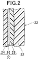
- FIG. 2 is an enlarged cross-sectional view of a cylindrical side wall portion of a double container manufactured by the double container manufacturing method of the first embodiment, taken along line II-II in FIG.
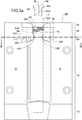
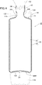
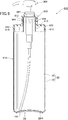
- FIG. It is a longitudinal cross-sectional view of the molded article manufactured by the manufacturing method of the double container of 1st Embodiment.
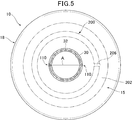
- 5 is a cross-section of the neck shoulder along line VV in FIG.
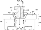
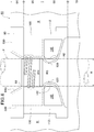
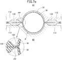
- FIG. 3B is an explanatory diagram of a process of forming gap burrs in the method for manufacturing a double container according to the first embodiment, taken along line VII-VII in FIG. 3A, in a state where the split mold is in contact with the parison P.
- FIG. 3B is an explanatory diagram of a process of forming gap burrs in the method for manufacturing a double container according to the first embodiment, taken along line VII-VII in FIG. 3A, in a state where the split mold starts to deform the parison P.
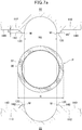
- FIG. 8 is a longitudinal sectional view of the bottom portion taken along line VIII-VIII in FIG. 1. It is sectional drawing of the double container of 5th Embodiment. It is sectional drawing of the double container of 6th Embodiment.
- the double container 10 manufactured by the manufacturing method of the first embodiment includes a mouth portion 12, a neck shoulder portion 14, a cylindrical portion 18, a bottom portion 20, and a cap 200 with a pump 300.
- the cylindrical portion side surface 22 of the cylindrical portion 18 has a low-density polyethylene (LDPE) layer 24 from the inside, as shown in FIGS. It consists of an adhesive layer 26 such as a polyolefin-based adhesive resin, three flexible inner layers 30 of an ethylene vinyl alcohol copolymer (EVOH) layer 28, and a rigid outer layer 32 of polypropylene (PP). There is no adhesion between the flexible inner layer 30 and the rigid outer layer 32, and it can be easily peeled off.
- LDPE low-density polyethylene
- the double container manufacturing method of the first embodiment forms a split mold (not shown) by joining a pair of partial molds 60 whose front view is shown in FIG. 3A with a mating surface H (see FIG. 6). And use it.
- the partial mold 60 includes a mouth burr region 64, a mouth region 66, a neck shoulder region 68, a cylindrical side wall region 70, and a bottom region 72.
- the mouth burr part region 64 is a part that forms an unnecessary upper end 92 of the parison P indicated by an imaginary line 92 and is finally cut off.
- a mouth burr mold part 80 acting as a mold is made of a steel material SKD11 and embedded in an extended part of the cylindrical side wall part region 70 made of aluminum 7075.
- the metal blow pin 84 partially inserted into the parison P has a large diameter cylindrical portion 84L and a small diameter cylindrical portion 84S, and has a vertical through hole 86 through which blow air passes in the center.
- the tip portion of the blow pin 84 is pushed into the parison P as shown in FIG. Subsequently, as shown in FIG. 3c, when air is blown into the parison P from the blow pin 84, the upper end portion of the parison P is pushed and widened by the blown-out air.
- the lower edge corner portion 88 of the large-diameter cylindrical portion 84 ⁇ / b> L of the blow pin 84 comes into contact with the parison P and the space between the blow pin 84 and the parison P is closed.
- the parison P is pressed against the mouth mold part 100 by the pressure of the air blown from the blow pin 84, and the mouth 12 is formed.
- the lower edge corner portion 88 of the large-diameter cylindrical portion 84 ⁇ / b> L of the blow pin 84 contacts the upper wide conical surface 80 ⁇ / b> C extending upward from the upper end portion 90 of the mouth portion mold portion 100. By this contact, the parison P is cut and the burr 92 can be removed.
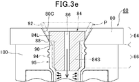
- the mouth mold part 100 is made of a steel material NAK55, and is embedded in an extension of the cylindrical side region 70 made of aluminum 7075.
- the neck shoulder 14 of the double container 10 is rigid on a surface A corresponding to a mating surface H of a partial mold (none of which is shown in FIG. 5) constituting the split mold.
- the outer layer 32 is interrupted to form an outer layer gap 110, and the flexible inner layer 30 is exposed in the outer layer gap 110. The situation where the outer layer gap 110 is formed will be described later.
- the flexible inner layer 30 and the rigid outer layer 32 are not adhesive as described above and can be easily peeled off. Therefore, when the volume of the space created by the flexible inner layer 30 decreases, the flexible inner layer 30 is separated from the rigid outer layer 32, and the outside air flows between the flexible inner layer 30 and the rigid outer layer 32 from the outer layer gap 110.
- a cap 200 with a pump 300 is screwed into the mouth portion 12 of the formed double container 10.
- the cap 200 has a mouth thread 94 that is threadedly engaged with a cap thread 96 formed in the mouth 12 on the inner surface.
- the cap 200 has a vent hole 206 and a packing 207 at the inner flange (upper end).
- the upper edge of the mouth 12 abuts against the packing 207, and at the same time, the lower end of the cap 200 is the inclined surface 15 of the neck shoulder 14, that is, the large diameter. Abuts against the part.
- the packing 207 is crushed as shown in FIG.
- the slope portion of the mouth portion 12 and the neck shoulder portion 14 is formed in the portion where the outer layer gap 110 between the mouth portion 12 and the slope portion 15 of the neck shoulder portion 14 is formed, that is, the small outer diameter portion.
- a force is provided that pulls away from 15 and increases the diameter of the small outer diameter portion.
- the outer layer gap 110 is completely opened or the opening area is enlarged, and it becomes easy for outside air to flow from the outer layer gap 110 into the flexible inner layer 30 and the rigid outer layer 32.
- the neck / shoulder mold part 112 for molding the neck / shoulder part 14 of the double container 10 is made of steel NAK 55 integrally with the mouth mold part 100, as shown in FIGS. Embedded in an extension of the cylindrical side region 70 made of aluminum 7075.
- the molding surface of the neck shoulder portion 14 has an innermost distance RS of the mating surface H of the portion to create the outer layer gap 110 of the neck shoulder region 68 of the partial mold 60 with respect to the parison P of the outer diameter R, for example, 71.4% of the outer diameter R of the parison P.
- the innermost distance RS of the mating surface H of the portion where the outer layer gap 110 of the neck-shoulder region 68 of the partial mold 60 is made is 99% to 50% of the outer diameter R of the parison P, more preferably It is 95% to 60%, more preferably 95% to 70%.
- This interval RS is determined in consideration of the environmental temperature, the temperature of the parison P, the thickness and the diameter of the parison P, and the like so as to obtain the optimum size of the outer layer gap 110 and the ease of excision of gap burrs described later. It is done.
- the neck shoulder region 68 of the partial mold 60 for molding the neck shoulder 14 of the double container 10 is a numerical example, as shown in FIGS. 6 and 7a, the inner diameter of the parison P is 17.0 mm and the outer diameter R. Is 21.0 mm, the outer diameter PR of the mouth portion 12 of the molded product is 21.5 mm, and the inner diameter is 17.3 mm, the minimum diameter portion of the mating surface H of the neck shoulder portion 14 that attempts to form the outer layer gap 110, that is, the neck shoulder
- the interval RS between the mold parts 112 is 15.0 mm (71.4% of the outer diameter of the parison P) as described above.
- the temperature of the parison P at the time of molding is 190.0 ° C., and the mold temperature is 19.0 ° C.
- the sandwiching width in the horizontal direction on the mating surface H of the sandwiching portion 120 that attempts to create the outer layer gap 110 on the mating surface H is 0.2 mm.
- a gap burr recess 140 (see FIGS. 4 and 6) for forming a gap burr 130 is formed outside the sandwiched portion 120 on the mating surface H.
- the gap burr recess 140 has a depth D of 1.5 mm, and an inclined surface 142 inclined by 45 ° with respect to the mating surface H is formed around the entire gap burr recess 140.
- the process of forming the outer layer gap 110 of the double container 10 manufactured by the manufacturing method of the first embodiment is as follows. As shown in FIGS. 3a, 6 and 7a, the parison P in a formable state is arranged in a centered manner between a pair of facing partial molds 60.
- a gap burr can be formed only in one place. It is also possible to form gap burrs in the mouth portion and the cylindrical portion other than the neck shoulder portion.
- the pair of partial molds 60 for making the split mold is moved toward the parison P with respect to each other.
- the innermost portion M of the mating surface H of the partial mold 60 has an interval between the mating surfaces H of the pair of partial molds 60, for example, 8.0 mm.
- the left and right sides contact the outer peripheral surface of the parison P.
- the sandwiching portion 120 of the mating surface H includes the folded inner flexible layer 30 at the center portion and the rigid outer layers 32 on both sides thereof. Is inserted.
- the rigid outer layer 32 is crushed and extends to the inside of the gap burr recess 140.
- the interval between the sandwiching portions 120 of the mating surface H, that is, the thickness of the parison P is about 0.05 to 0.3 mm.
- the extruded parison P forms a gap burr 130 via the pinch part PP.
- Both surfaces of the mating surfaces of the partial molds of the split mold are flat surfaces, and the pinch portion PP becomes a flat plate shape when the split mold is formed by combining the partial molds.
- the pinch portion PP indicates a very thin portion of the parison P that exists between the mating surfaces when the mating surfaces sandwich the parison P therebetween.
- the bottom 20 of the double container 10 is formed by sandwiching the middle part of the parison P with the bottom region 72 of the partial mold 60 when the partial mold 60 is combined to form a split mold.
- the portion of the bottom region 72 that acts as a mold is made of steel NAK 55, similar to the mouth mold portion 100 and neck shoulder mold portion 112, and is embedded in an extension of the cylindrical side region 70 made of aluminum 7075. It is.
- the parison P below the bottom portion 20 is formed with a bottom pinch portion BPP and a bottom burr 144.
- the gap burr 130 and bottom burr 144 are easily removed to complete the double container.
- the center crossing part of the bottom part 20 is integrated by pressing the parisons P in the front-rear direction region of the mating surface H of the split mold against each other, and the outer layer 32 is formed on both sides of the integrated part.
- the outer layer 32 is formed on both sides of the integrated part.
- the double container 10 manufactured by the manufacturing method of the second embodiment includes a flexible inner layer 30 of polyamide (PA) and a rigid outer layer 32 of polypropylene (PP). There is no adhesion between the flexible inner layer 30 and the rigid outer layer 32, and it can be easily peeled off.
- PA polyamide
- PP polypropylene
- the neck shoulder region 68 of the partial mold 60 for molding the neck shoulder 14 of the double container 10 has an inner diameter of the parison P of 16.5 mm, an outer diameter R of 20.5 mm, and an outer diameter of the mouth 12 of the molded product.
- the PR is 21.5 mm and the inner diameter is 17.3 mm
- the minimum diameter portion of the mating surface H of the neck shoulder 14 where the outer layer gap 110 is to be made, that is, the distance RS between the neck shoulder mold portions 112 is 15.5 mm ( 72.1% of the outer diameter of the parison P).
- the temperature of the parison P during molding is 190.0 ° C., and the mold temperature is 19.0 ° C.
- the sandwiching width on the mating surface H of the sandwiching portion 120 to create the outer layer gap 110 on the mating surface H is 0.1 mm.
- a gap burr recess 140 (see FIG. 6) for forming a gap burr 130 is formed outside the sandwiched portion 120 on the mating surface H.
- the gap flash recess 140 has a depth D of 2.0 mm, and a slope 142 inclined by 30 ° with respect to the mating surface H is formed around the entire gap burr recess 140.
- the double container manufactured by the manufacturing method of the third embodiment includes, from the inside, a low-density polyethylene (LDPE) layer, an adhesive layer such as a polyolefin-based adhesive resin, and an ethylene vinyl alcohol copolymer (EVOH) layer.
- LDPE low-density polyethylene
- EVOH ethylene vinyl alcohol copolymer
- the mouth mold portion 100 and the neck shoulder mold portion 112 are integrally made of die steel SKD11.
- the neck shoulder region 68 of the partial mold 60 for molding the neck shoulder 14 of the double container 10 has an inner diameter of the parison P of 23.5 mm, an outer diameter R of 28.5 mm, and an outer diameter of the mouth 12 of the molded product.
- the PR is 29.0 mm and the inner diameter is 23.5 mm
- the minimum diameter portion of the mating surface H of the neck shoulder 14 where the outer layer gap 110 is to be formed, that is, the distance RS between the neck shoulder mold portions 112 is 20.0 mm ( 70.1% of the outer diameter of the parison P).
- the temperature of the parison P during molding is 210.0 ° C., and the mold temperature is 19.0 ° C.
- the sandwiching width on the mating surface H of the sandwiching portion 120 to create the outer layer gap 110 on the mating surface H is 0.1 mm.
- a gap burr recess 140 (see FIG. 6) for forming a gap burr 130 is formed outside the sandwiched portion 120 on the mating surface H.
- the gap burr recess 140 has a depth D of 2.0 mm, and an inclined surface 142 inclined by 30 ° with respect to the mating surface H is formed around the entire gap burr recess 140.
- the double container manufactured by the manufacturing method of the fourth embodiment includes, from the inside, a blend layer of low density polyethylene (LDPE) and an adhesive resin, an ethylene vinyl alcohol copolymer (EVOH), a polyolefin adhesive resin, and the like.
- Adhesive layer Adhesive layer, four flexible inner layers 30 of ethylene vinyl alcohol copolymer (EVOH), and a rigid outer layer 32 of polypropylene (PP).
- PP polypropylene
- the neck shoulder region 68 of the partial mold 60 for molding the neck shoulder 14 of the double container 10 has an inner diameter of the parison P of 15.5 mm, an outer diameter R of 20.0 mm, and an outer diameter of the mouth 12 of the molded product.
- the PR is 20.5 mm and the inner diameter is 17.3 mm
- the smallest diameter portion of the mating surface H of the neck shoulder 14 where the outer layer gap 110 is to be made, that is, the distance RS between the neck shoulder mold portions 112 is 13.0 mm. (65.0% of the outer diameter of the parison P).
- the temperature of the parison P during molding is 190.0 ° C., and the mold temperature is 19.0 ° C.
- the sandwiching width on the mating surface H of the sandwiching portion 120 to create the outer layer gap 110 on the mating surface H is 0.1 mm.
- a gap burr recess 140 (see FIG. 6) for forming a gap burr 130 is formed outside the sandwiched portion 120 on the mating surface H.
- the gap burr recess 140 has a depth D of 1.5 mm, and an inclined surface 142 inclined by 60 ° with respect to the mating surface H is formed on the entire periphery of the gap burr recess 140.
- the gap burr recess 140 is formed on the mating surface H.
- an excess parison recess 500 for receiving the parison material protruding from the split mold at the time of blowing can be formed in the vicinity of the mouth burr part region 64, the mouth region 66, and the like (see FIG. 3a).
- the double container 610 of the fifth embodiment is different from the double container 10 of the first embodiment in the configuration of the upper portion of the cylindrical portion 618 and the cap 620. Accordingly, the same parts of the double container 610 of the fifth embodiment as those of the double container 10 of the first embodiment are denoted by the same reference numerals as those of the first embodiment in the drawings, and the description thereof is omitted.
- a cap 620 with a pump 300 is screwed into the mouth 612 of the double container 610.
- the cap 620 has a mouth thread 696 that is screwed into a cap thread 694 formed in the mouth 612 on the inner surface.
- the cap 620 has a ventilation hole 630 and a packing 207 on the inner flange (upper end).
- the mouth portion 612 and the cylindrical portion 618 are formed in a portion where the outer layer gap 110 is formed between the mouth portion 612 and the peripheral edge portion 615 of the upper end plane of the cylindrical portion 618, that is, a small outer diameter portion. Force is provided to pull away from the peripheral edge 615 of the upper end plane and to increase the diameter of the small outer diameter portion. As a result, the outer layer gap 110 is completely opened or the opening area is enlarged, and it becomes easy for outside air to flow from the outer layer gap 110 into the flexible inner layer 30 and the rigid outer layer 32.
- the double container 710 of the sixth embodiment is different from the double container 10 of the first embodiment in the configuration of the upper portion of the cylindrical portion 718 and the cap 720. Accordingly, the same parts of the double container 710 of the sixth embodiment as those of the double container 10 of the first embodiment are denoted by the same reference numerals as those of the first embodiment in the drawings, and the description thereof is omitted.
- a cap 720 with a pump 300 is screwed into the mouth 712 of the double container 710.
- the cap 720 has a mouth thread 796 that is screwed into a cap thread 794 formed in the mouth 712 on the inner surface.
- the cap 720 has a ventilation hole 730 and a packing 207 on the inner flange (upper end).
- the upper end edge of the mouth part 712 contacts the packing 207, and at the same time, the lower end part of the cap 720 is formed at an intermediate position of the conical part of the cylindrical part 718.
- the intermediate flat ring zone 715 is brought into contact.
- the mouth portion 712 and the cylindrical portion 718 are formed in a portion where the outer layer gap 110 is formed between the mouth portion 712 and the intermediate flat ring portion 715 of the cylindrical portion 718, that is, a small outer diameter portion. Force of separating the intermediate flat ring zone 715 and increasing the diameter of the small outer diameter portion. As a result, the outer layer gap 110 is completely opened or the opening area is enlarged, and it becomes easy for outside air to flow from the outer layer gap 110 into the flexible inner layer 30 and the rigid outer layer 32.
Abstract
Description
すなわち、一般の容器において、収容物の充填後、容器内の空間を真空にしたり窒素ガス等の不活性ガスを充填すること等によって、充填容器を開封するまで収容物の酸化を防ぐことは容易である。しかし、一般的な剛性容器では、容器を開封して収容物を一部消費し、容器内に使用残りの収容物が残留している状態では、容器内に収容物の消費量に対応した容積の外気が入り、残留収容物が酸化する。この酸化を防ぐため、収容物に酸化防止剤を含有させることもある。 It is desirable that the container can prevent oxidation of the contained material without touching the outside air even if the amount of the contained material is reduced by using a part of the contained material.
That is, in a general container, after filling the contents, it is easy to prevent the contents from being oxidized until the filling container is opened by evacuating the space in the container or filling with an inert gas such as nitrogen gas. It is. However, in the case of a general rigid container, when the container is opened and a part of the stored item is consumed, and the remaining used item remains in the container, the volume corresponding to the consumed amount of the stored item in the container The outside air enters and the residual contents are oxidized. In order to prevent this oxidation, the contents may contain an antioxidant.
本発明は、比較的剛性な外容器と、該外容器内で収容物の充填量に対応して容量を変更可能な柔軟内容器とからなる二重容器において、特に外気を入れるための開口に関する上述した問題点に鑑みてなされたものであって、従来と大きく変わらない成形装置によって容易に製造可能で、比較的剛性な外容器と、該外容器内で収容物の充填量に対応して容量を変更可能な内容器を有する二重容器において、外気を入れるための開口を、極めて容易に且つ確実に、従来技術による加工コストより低いコストで形成することができる二重容器の製造方法を提供することを目的とする。 (Object of invention)
The present invention relates to a double container comprising a relatively rigid outer container and a flexible inner container whose capacity can be changed in accordance with the filling amount of the contents in the outer container, and particularly relates to an opening for introducing outside air. It was made in view of the above-described problems, and can be easily manufactured by a molding apparatus that is not greatly different from the conventional one, and corresponds to a relatively rigid outer container and the filling amount of the contents in the outer container. In a double container having an inner container whose capacity can be changed, a method of manufacturing a double container capable of forming an opening for putting outside air very easily and surely at a cost lower than the processing cost according to the prior art. The purpose is to provide.
前記二重容器のキャップ螺合部分、容器本体部分又はこれらの間に、一定の外径を有する大外径部分を形成し、さらに該大径部部分と前記キャップ螺合部分の間に前記大外径部分より小さい外径を有する小外径部分とを形成し、前記一対の部分金型が組み合わされて前記割金型を作るために相互に近寄る際に、前記一対の部分金型の合わせ面の少なくとも一部が、前記パリソンの前記小外径部分を挟んで隙間バリを形成するステップAと、
ステップAにおいて形成された前記隙間バリを除去するステップBと、
前記隙間バリを除去した前記小外径部分に、前記キャップの螺合によって前記キャップ螺合部分と前記大外径部分を引き離す方向の張力を加えるステップCと
を有することを特徴とする二重容器の製造方法成である。 The first invention uses a split mold in which a pair of partial molds are combined from a parison having at least two layers of an inner layer and an outer layer that form a rigid outer layer container portion and a flexible inner layer container portion that can be separated from each other after molding. The container is molded, and outside air is introduced between the rigid outer layer container part and the flexible inner layer container part, and the capacity of the flexible inner layer container part is reduced while maintaining the shape of the rigid outer layer container part. And a method of manufacturing a double container having a screw cap,
A large outer diameter portion having a constant outer diameter is formed between the cap screwing portion, the container main body portion of the double container, and the large diameter portion between the large diameter portion and the cap screwing portion. Forming a small outer diameter portion having an outer diameter smaller than the outer diameter portion, and combining the pair of partial molds when the pair of partial molds are combined to approach each other to form the split mold A step A in which at least a part of the surface forms a gap burr across the small outer diameter portion of the parison;
Step B for removing the gap burrs formed in Step A;
And a step C of applying tension in a direction to separate the cap screwed portion and the large outer diameter portion to the small outer diameter portion from which the gap burr has been removed by screwing the cap. This is the manufacturing method.
前記二重容器のキャップ螺合部分、容器本体部分、又はこれらの間に、一定の外径を有する大外径部分と、さらに該大径部部分と前記キャップ螺合部分の間に該大径部より小さい外径を有する小外径部分とが形成されていて、
前記一対の部分金型が組み合わされて前記割金型を作るために相互に近寄る際に、前記一対の部分金型の合わせ面の少なくとも一部が前記パリソンの前記小外径部分を挟んで形成された隙間バリが、除去されており、
前記キャップの螺合が、前記隙間バリを除去した前記小外径部分に、前記キャップ螺合部分と前記大外径部分とを引き離す方向の張力を加える
ことを特徴とする二重容器である。 According to a second aspect of the present invention, there is provided a split mold in which a pair of partial molds are combined from a parison having at least two layers of an inner layer and an outer layer that form a rigid outer layer container portion and a flexible inner layer container portion that can be separated from each other after molding. A container is molded using, introducing the outside air between the rigid outer layer container part and the flexible inner layer container part, while maintaining the shape of the rigid outer layer container part, the capacity of the flexible inner layer container part A double container that is reduced and has a threaded cap,
The cap screwed portion, the container main body portion of the double container, or a large outer diameter portion having a constant outer diameter between them, and the large diameter between the large diameter portion portion and the cap screwed portion. A small outer diameter portion having an outer diameter smaller than the portion is formed,
When the pair of partial molds come together to make the split mold, at least a part of the mating surfaces of the pair of partial molds is formed with the small outer diameter portion of the parison interposed therebetween The gap burrs made have been removed,
The double container is characterized in that the screwing of the cap applies a tension in a direction to separate the cap screwing part and the large outer diameter part to the small outer diameter part from which the gap burr is removed.
第1発明において、前記一対の部分金型の合わせ面の少なくとも一部が、パリソンを水平対向位置の両側部分で挟み込むことを特徴とする。
第1発明において、前記一対の部分金型の合わせ面の少なくとも一部が、パリソンの一カ所を挟み込むことを特徴とする。
第1発明において、前記一対の部分金型の合わせ面の一部が前記パリソンを挟み込む部分の外側に、前記パリソンから作られる摘み突起部を形成することを特徴とする。
第1発明において、前記一対の部分金型の当たり面の一部が前記パリソンを挟み込む部分は、二重容器の首肩部であることを特徴とする。
第1発明において、前記一対の部分金型の当たり面の一部が前記パリソンを挟み込む部分は、二重容器の口部であることを特徴とする。
第1発明において、前記一対の部分金型の当たり面の一部が前記パリソンを挟み込む部分は、二重容器の前記螺合部分であることを特徴とする。 (Embodiment of the first invention)
In the first invention, at least a part of the mating surfaces of the pair of partial molds is characterized in that the parison is sandwiched between both sides of the horizontally opposed position.
In the first invention, at least part of the mating surfaces of the pair of partial dies sandwiches one part of the parison.
In the first invention, a part of the mating surfaces of the pair of partial molds is characterized in that a knob projection made from the parison is formed outside a portion sandwiching the parison.
1st invention WHEREIN: The part which a part of contact surface of a pair of said partial die pinches | interposes the said parison is a neck shoulder part of a double container, It is characterized by the above-mentioned.
1st invention WHEREIN: The part which a part of contact surface of a pair of said partial die pinches | interposes the said parison is a mouth part of a double container, It is characterized by the above-mentioned.
1st invention WHEREIN: The part into which a part of contact surface of a pair of said partial die pinches | interposes the said parison is the said screwing part of a double container, It is characterized by the above-mentioned.
第2発明において、前記隙間バリが除去された位置が、前記キャップ螺合部分、容器本体部分、又はこれらの間の水平対向位置の両側部分であることを特徴とする。
第2発明において、前記隙間バリが除去された位置が、前記キャップ螺合部分、容器本体部分、又はこれらの間の一カ所であることを特徴とする。
第2発明において、前記隙間バリが除去された位置が、二重容器の首肩部であることを特徴とする。
第2発明において、前記隙間バリが除去された位置が、二重容器の口部であることを特徴とする。
第2発明において、前記隙間バリが除去された位置が、二重容器の前記キャップ螺合部分であることを特徴とする。 (Embodiment of the second invention)
2nd invention WHEREIN: The position from which the said clearance gap burr | flash was removed is the both-sides part of the said cap screwing part, a container main-body part, or the horizontal opposing position between these.
2nd invention WHEREIN: The position from which the said clearance gap burr | flash was removed is the said cap screwing part, a container main-body part, or one place between these.
2nd invention WHEREIN: The position where the said clearance gap burr | flash was removed is a neck shoulder part of a double container, It is characterized by the above-mentioned.
2nd invention WHEREIN: The position from which the said clearance gap burr | flash was removed is a mouth part of a double container, It is characterized by the above-mentioned.
2nd invention WHEREIN: The position where the said clearance gap burr | flash was removed is the said cap screwing part of a double container, It is characterized by the above-mentioned.
第1実施形態の製造方法によって製造される二重容器10は、図1に示すように、口部12,首肩部14、円筒部18,底部20,及びポンプ300付きキャップ200からなる。 (First embodiment)
As shown in FIG. 1, the
続いて、図3cに示すように、エアがブローピン84からパリソンP内へ吹き込まれると、パリソンPの上方端部分が吹き出るエアによって上広形に押し広げられる。 In the manufacturing method of the double container of the first embodiment, first, the tip portion of the
Subsequently, as shown in FIG. 3c, when air is blown into the parison P from the
続いて、ブローピン84の大径筒部分84Lの下縁角部88が口部金型部分100の上端部90から上方へ延びる上広円錐面80Cに当接する。この当接によって、パリソンPが切断されて、口バリ92が除去可能となる。 Subsequently, as shown in FIG. 3 d, the lower
Subsequently, the lower
成形可能な状態のパリソンPを、図3a、図6及び図7aに示すように、向き合った一対の部分金型60の間に芯合わせして配置する。 The process of forming the
As shown in FIGS. 3a, 6 and 7a, the parison P in a formable state is arranged in a centered manner between a pair of facing
また、隙間バリを首肩部以外の口部や円筒部に形成することも可能である。 By arranging the parison P in a formable state so as to be eccentric between the pair of
It is also possible to form gap burrs in the mouth portion and the cylindrical portion other than the neck shoulder portion.
第2実施形態の製造方法によって製造される二重容器10は、ポリアミド(PA)の柔軟性内層30と、ポリプロピレン(PP)の剛性外層32とからなる。柔軟性内層30と剛性外層32の間には、接着性はなく、容易に剥離可能である。 (Second Embodiment)
The
第3実施形態の製造方法によって製造される二重容器は、内側から、低密度ポリエチレン(LDPE)層、ポリオフィン系接着性樹脂等の接着剤層、及びエチレンビニルアルコール共重合体(EVOH)層の3層の柔軟性内層30と、ポリカーボネート(PC)の剛性外層32とからなる。柔軟性内層30と剛性外層32の間には、接着性はなく、容易に剥離可能である。
口部金型部分100及び首肩部金型部分112は、一体的に、ダイス鋼SKD11によって作られる。 (Third embodiment)
The double container manufactured by the manufacturing method of the third embodiment includes, from the inside, a low-density polyethylene (LDPE) layer, an adhesive layer such as a polyolefin-based adhesive resin, and an ethylene vinyl alcohol copolymer (EVOH) layer. 3 layers of a flexible
The
第4実施形態の製造方法によって製造される二重容器は、内側から、低密度ポリエチレン(LDPE)と接着性樹脂のブレンド層、エチレンビニルアルコール共重合体(EVOH)、ポリオフィン系接着性樹脂等の接着剤層、及びエチレンビニルアルコール共重合体(EVOH)の4層の柔軟性内層30と、ポリプロピレン(PP)の剛性外層32とからなる。柔軟性内層30と剛性外層32の間には、接着性はなく、容易に剥離可能である。
口部金型部分100及び首肩部金型部分112は、一体的に、プリハードン鋼(NAK55)によって作られる。 (Fourth embodiment)
The double container manufactured by the manufacturing method of the fourth embodiment includes, from the inside, a blend layer of low density polyethylene (LDPE) and an adhesive resin, an ethylene vinyl alcohol copolymer (EVOH), a polyolefin adhesive resin, and the like. Adhesive layer, four flexible
The
第5実施形態の二重容器610は、図9に示すように、円筒部618の上方部分とキャップ620の構成が、第1実施形態の二重容器10と異なる。従って、第5実施形態の二重容器610の第1実施形態の二重容器10と同一の部分は、図面に第1実施形態と同一の符号を付してその説明を省略する。 (Fifth embodiment)
As shown in FIG. 9, the
キャップネジ山694と口部ネジ山696の螺合がほぼ完了すると、口部612の上端縁部がパッキン207に当接し、同時にキャップ620の下端部が円筒部618の上端平面の周縁部615に当接する。 As shown in FIG. 9, a
When the screwing of the
第6実施形態の二重容器710は、図10に示すように、円筒部718の上方部分とキャップ720の構成が、第1実施形態の二重容器10と異なる。従って、第6実施形態の二重容器710の第1実施形態の二重容器10と同一の部分は、図面に第1実施形態と同一の符号を付してその説明を省略する。 (Sixth embodiment)
As shown in FIG. 10, the
キャップネジ山794と口部ネジ山796の螺合がほぼ完了すると、口部712の上端縁部がパッキン207に当接し、同時にキャップ720の下端部が円筒部718の円錐部分の中間位置に形成された中間平面輪帯部715に当接する。 As shown in FIG. 10, a
When the screwing of the
PP ピンチ部
10 二重容器
18 円筒部
22 円筒部側面
24 低密度ポリエチレン(LDPE)層
26 接着剤層
28 エチレンビニルアルコール共重合体(EVOH)層
30 柔軟性内層
32 剛性外層
60 部分金型
64 口バリ部領域
66 口部領域
68 首肩部領域
70 円筒側壁部領域
72 底部領域
80 口バリ金型部分
84 ピン
86 縦貫通孔
88 下縁角部
92 口バリ
100 口部金型部分
110 外層隙間
112 首肩部金型部分
120 挟み部分
130 隙間バリ
140 隙間バリ凹部
142 斜面
144 底バリ
500 余剰パリソン凹部 P Parison
Claims (13)
- 成形後互いに剥離可能な剛性外層容器部と柔軟性内層容器部とを形成する内層及び外層の少なくとも2層を有するパリソンから、一対の部分金型を組み合わせた割金型を使用して容器を成形し、前記剛性外層容器部と前記柔軟性内層容器部との間に外気を導入して、前記剛性外層容器部の形状を維持しながら前記柔軟性内層容器部の容量を縮小させ、かつ螺合キャップを有する二重容器の製造方法において、
前記二重容器のキャップ螺合部分、容器本体部分又はこれらの間に、一定の外径を有する大外径部分を形成し、さらに該大径部部分と前記キャップ螺合部分の間に前記大外径部分より小さい外径を有する小外径部分とを形成し、前記一対の部分金型が組み合わされて前記割金型を作るために相互に近寄る際に、前記一対の部分金型の合わせ面の少なくとも一部が、前記パリソンの前記小外径部分を挟んで隙間バリを形成するステップAと、
ステップAにおいて形成された前記隙間バリを除去するステップBと、
前記隙間バリを除去した前記小外径部分に、前記キャップの螺合によって前記キャップ螺合部分と前記大外径部分を引き離す方向の張力を加えるステップCと
を有することを特徴とする二重容器の製造方法。 A container is molded from a parison having at least two layers of an inner layer and an outer layer that form a rigid outer layer container part and a flexible inner layer container part that can be peeled from each other after molding, using a split mold that combines a pair of partial molds. And introducing external air between the rigid outer layer container part and the flexible inner layer container part to reduce the capacity of the flexible inner layer container part while maintaining the shape of the rigid outer layer container part, and screwing In the method for producing a double container having a cap,
A large outer diameter portion having a constant outer diameter is formed between the cap screwing portion, the container main body portion of the double container, and the large diameter portion between the large diameter portion and the cap screwing portion. Forming a small outer diameter portion having an outer diameter smaller than the outer diameter portion, and combining the pair of partial molds when the pair of partial molds are combined to approach each other to form the split mold A step A in which at least a part of the surface forms a gap burr across the small outer diameter portion of the parison;
Step B for removing the gap burrs formed in Step A;
And a step C of applying tension in a direction to separate the cap screwed portion and the large outer diameter portion to the small outer diameter portion from which the gap burr has been removed by screwing the cap. Manufacturing method. - 前記一対の部分金型の合わせ面の少なくとも一部が、パリソンを水平対向位置の両側部分で挟み込むことを特徴とする請求項1に記載の二重容器の製造方法。 The method for manufacturing a double container according to claim 1, wherein at least part of the mating surfaces of the pair of partial molds sandwich the parison between both side portions at the horizontally opposed position.
- 前記一対の部分金型の合わせ面の少なくとも一部が、パリソンの一カ所を挟み込むことを特徴とする請求項1に記載の二重容器の製造方法。 The method for producing a double container according to claim 1, wherein at least a part of the mating surfaces of the pair of partial molds sandwiches one part of the parison.
- 前記一対の部分金型の合わせ面の一部が前記パリソンを挟み込む部分の外側に、前記パリソンから作られる摘み突起部を形成することを特徴とする請求項1に記載の二重容器の製造方法。 2. The method for manufacturing a double container according to claim 1, wherein a knob protrusion made from the parison is formed outside a portion where the mating surfaces of the pair of partial molds sandwich the parison. .
- 前記一対の部分金型の当たり面の一部が前記パリソンを挟み込む部分は、二重容器の首肩部であることを特徴とする請求項1に記載の二重容器の製造方法。 2. The method of manufacturing a double container according to claim 1, wherein a part of a contact surface of the pair of partial molds sandwiching the parison is a neck shoulder portion of the double container.
- 前記一対の部分金型の当たり面の一部が前記パリソンを挟み込む部分は、二重容器の口部であることを特徴とする請求項1に記載の二重容器の製造方法。 2. The method for manufacturing a double container according to claim 1, wherein a part of a contact surface of the pair of partial molds sandwiches the parison is a mouth of the double container.
- 前記一対の部分金型の当たり面の一部が前記パリソンを挟み込む部分は、二重容器の前記螺合部分であることを特徴とする請求項1に記載の二重容器の製造方法。 The method for manufacturing a double container according to claim 1, wherein a part of a contact surface of the pair of partial molds sandwiching the parison is the screwed part of the double container.
- 成形後互いに剥離可能な剛性外層容器部と柔軟性内層容器部とを形成する内層及び外層の少なくとも2層を有するパリソンから、一対の部分金型を組み合わせた割金型を使用して容器を成形され、前記剛性外層容器部と前記柔軟性内層容器部との間に外気を導入して、前記剛性外層容器部の形状を維持しながら前記柔軟性内層容器部の容量を縮小させ、かつ螺合キャップを有する二重容器であって、
前記二重容器のキャップ螺合部分、容器本体部分、又はこれらの間に、一定の外径を有する大外径部分と、該大径部より小さい外径を有する小外径部分とが形成されていて、
前記一対の部分金型が組み合わされて前記割金型を作るために相互に近寄る際に、前記一対の部分金型の合わせ面の少なくとも一部が前記パリソンの前記小外径部分を挟んで形成された隙間バリが、除去されており、
前記キャップの螺合が、前記隙間バリを除去した前記小外径部分に、前記キャップ螺合部分と前記大外径部分とを引き離す方向の張力を加える
ことを特徴とする二重容器。 A container is molded from a parison having at least two layers of an inner layer and an outer layer that form a rigid outer layer container part and a flexible inner layer container part that can be peeled from each other after molding, using a split mold that combines a pair of partial molds. Introducing outside air between the rigid outer layer container part and the flexible inner layer container part to reduce the capacity of the flexible inner layer container part while maintaining the shape of the rigid outer layer container part, and screwing A double container with a cap,
A cap screw part, a container body part of the double container, or a large outer diameter part having a constant outer diameter and a small outer diameter part having an outer diameter smaller than the large diameter part are formed between them. And
When the pair of partial molds come together to make the split mold, at least a part of the mating surfaces of the pair of partial molds is formed with the small outer diameter portion of the parison interposed therebetween The gap burrs made have been removed,
The double container according to claim 2, wherein the screwing of the cap applies tension in a direction to separate the cap screwing part and the large outer diameter part to the small outer diameter part from which the gap burr is removed. - 前記隙間バリが除去された位置が、前記キャップ螺合部分、容器本体部分、又はこれらの間の水平対向位置の両側部分であることを特徴とする請求項8に記載の二重容器。 The double container according to claim 8, wherein the position where the gap burr is removed is the cap screwing part, the container main body part, or both side parts of a horizontally opposed position therebetween.
- 前記隙間バリが除去された位置が、前記キャップ螺合部分、容器本体部分、又はこれらの間の一カ所であることを特徴とする請求項8に記載の二重容器。 The double container according to claim 8, wherein the position where the gap burr is removed is the cap screwing part, the container body part, or one place between them.
- 前記隙間バリが除去された位置が、二重容器の首肩部であることを特徴とする請求項8に記載の二重容器。 The double container according to claim 8, wherein the position where the gap burr is removed is a neck shoulder portion of the double container.
- 前記隙間バリが除去された位置が、二重容器の口部であることを特徴とする請求項8に記載の二重容器。 The double container according to claim 8, wherein the position where the gap burr is removed is the mouth of the double container.
- 前記隙間バリが除去された位置が、二重容器の前記キャップ螺合部分であることを特徴とする請求項8に記載の二重容器。 The double container according to claim 8, wherein the position where the gap burr is removed is the cap screwing portion of the double container.
Priority Applications (4)
| Application Number | Priority Date | Filing Date | Title |
|---|---|---|---|
| US15/529,639 US10315803B2 (en) | 2015-10-26 | 2016-10-26 | Double container assembly and manufacturing method therefor |
| KR1020177014044A KR101926291B1 (en) | 2015-10-26 | 2016-10-26 | Double container assembly and manufacturing method therefor |
| CN201680003836.4A CN107000883B (en) | 2015-10-26 | 2016-10-26 | Double container and its manufacturing method |
| EP16859836.5A EP3222542B1 (en) | 2015-10-26 | 2016-10-26 | Double container and manufacturing method for same |
Applications Claiming Priority (2)
| Application Number | Priority Date | Filing Date | Title |
|---|---|---|---|
| JP2015-209952 | 2015-10-26 | ||
| JP2015209952A JP6850531B2 (en) | 2015-10-26 | 2015-10-26 | Double container and its manufacturing method |
Publications (1)
| Publication Number | Publication Date |
|---|---|
| WO2017073606A1 true WO2017073606A1 (en) | 2017-05-04 |
Family
ID=58631678
Family Applications (1)
| Application Number | Title | Priority Date | Filing Date |
|---|---|---|---|
| PCT/JP2016/081711 WO2017073606A1 (en) | 2015-10-26 | 2016-10-26 | Double container and manufacturing method for same |
Country Status (6)
| Country | Link |
|---|---|
| US (1) | US10315803B2 (en) |
| EP (1) | EP3222542B1 (en) |
| JP (1) | JP6850531B2 (en) |
| KR (1) | KR101926291B1 (en) |
| CN (1) | CN107000883B (en) |
| WO (1) | WO2017073606A1 (en) |
Citations (2)
| Publication number | Priority date | Publication date | Assignee | Title |
|---|---|---|---|---|
| JPS5418704B2 (en) * | 1973-06-07 | 1979-07-10 | ||
| JP2003534148A (en) * | 2000-04-07 | 2003-11-18 | ベーリンガー インゲルハイム ファルマ ゲゼルシャフト ミット ベシュレンクテル ハフツング ウント コンパニー コマンディトゲゼルシャフト | Method of manufacturing container provided with pressure equalizing opening and container manufactured by the method |
Family Cites Families (14)
| Publication number | Priority date | Publication date | Assignee | Title |
|---|---|---|---|---|
| US4887744A (en) * | 1988-06-08 | 1989-12-19 | Williams Forrest D | Dispenser for a carbonated beverage bottle |
| US5405057A (en) * | 1993-10-21 | 1995-04-11 | Moore; David G. | Manually actuated pump |
| JP3368484B2 (en) | 1994-06-23 | 2003-01-20 | 株式会社吉野工業所 | Bottle and molding method thereof |
| JP3627946B2 (en) | 1996-07-29 | 2005-03-09 | 株式会社吉野工業所 | Double layer container |
| JP3398940B2 (en) * | 1999-12-13 | 2003-04-21 | キャニヨン株式会社 | Liquid ejection device |
| US6503440B2 (en) | 2000-04-07 | 2003-01-07 | Boehringer Ingelheim Pharma Kg | Process for making a container with a pressure equalization opening and containers produced accordingly |
| WO2003037725A1 (en) * | 2001-10-31 | 2003-05-08 | Yoshino Kogyosho Co., Ltd. | Blow-molded container |
| JP2006335398A (en) | 2005-05-31 | 2006-12-14 | Yoshino Kogyosho Co Ltd | Laminate container with its inner layer peelable, and its forming method |
| JP4803590B2 (en) | 2006-05-31 | 2011-10-26 | 株式会社吉野工業所 | Delami bottle |
| JP4936249B2 (en) | 2007-02-28 | 2012-05-23 | 株式会社吉野工業所 | Blow molded container made of synthetic resin |
| US8057733B2 (en) * | 2007-12-21 | 2011-11-15 | Silgan Plastics Corporation | Dosing bottle and method |
| JP2012250732A (en) | 2011-06-01 | 2012-12-20 | Keizo Fujita | Double structure container |
| JP6112385B2 (en) | 2012-08-31 | 2017-04-12 | 株式会社吉野工業所 | Blow molded container and manufacturing method thereof |
| JP6025040B2 (en) | 2012-10-31 | 2016-11-16 | 株式会社吉野工業所 | Blow molding container and blow molding method |
-
2015
- 2015-10-26 JP JP2015209952A patent/JP6850531B2/en active Active
-
2016
- 2016-10-26 CN CN201680003836.4A patent/CN107000883B/en active Active
- 2016-10-26 KR KR1020177014044A patent/KR101926291B1/en active IP Right Grant
- 2016-10-26 US US15/529,639 patent/US10315803B2/en active Active
- 2016-10-26 WO PCT/JP2016/081711 patent/WO2017073606A1/en active Application Filing
- 2016-10-26 EP EP16859836.5A patent/EP3222542B1/en active Active
Patent Citations (2)
| Publication number | Priority date | Publication date | Assignee | Title |
|---|---|---|---|---|
| JPS5418704B2 (en) * | 1973-06-07 | 1979-07-10 | ||
| JP2003534148A (en) * | 2000-04-07 | 2003-11-18 | ベーリンガー インゲルハイム ファルマ ゲゼルシャフト ミット ベシュレンクテル ハフツング ウント コンパニー コマンディトゲゼルシャフト | Method of manufacturing container provided with pressure equalizing opening and container manufactured by the method |
Non-Patent Citations (1)
| Title |
|---|
| See also references of EP3222542A4 * |
Also Published As
| Publication number | Publication date |
|---|---|
| EP3222542B1 (en) | 2021-09-01 |
| JP2017081584A (en) | 2017-05-18 |
| EP3222542A1 (en) | 2017-09-27 |
| US20170283115A1 (en) | 2017-10-05 |
| US10315803B2 (en) | 2019-06-11 |
| CN107000883A (en) | 2017-08-01 |
| EP3222542A4 (en) | 2018-06-20 |
| JP6850531B2 (en) | 2021-03-31 |
| KR101926291B1 (en) | 2018-12-06 |
| CN107000883B (en) | 2018-09-21 |
| KR20170074963A (en) | 2017-06-30 |
Similar Documents
| Publication | Publication Date | Title |
|---|---|---|
| WO2016027732A1 (en) | Double-walled container manufacturing method | |
| US11427368B2 (en) | Manufacturing method for double walled container | |
| TWI766934B (en) | Laminated peel container | |
| KR102590903B1 (en) | Delamination container | |
| WO2017142027A1 (en) | Double-layered container and method for production of same | |
| JP6025040B2 (en) | Blow molding container and blow molding method | |
| WO2017073606A1 (en) | Double container and manufacturing method for same | |
| JP7139057B2 (en) | delaminating container | |
| JP2019099212A (en) | Layered peeling container | |
| JP7137075B2 (en) | delaminating container | |
| JP2017214100A (en) | Molded product and production method and production device therefor |
Legal Events
| Date | Code | Title | Description |
|---|---|---|---|
| REEP | Request for entry into the european phase |
Ref document number: 2016859836 Country of ref document: EP |
|
| ENP | Entry into the national phase |
Ref document number: 20177014044 Country of ref document: KR Kind code of ref document: A |
|
| WWE | Wipo information: entry into national phase |
Ref document number: 15529639 Country of ref document: US |
|
| 121 | Ep: the epo has been informed by wipo that ep was designated in this application |
Ref document number: 16859836 Country of ref document: EP Kind code of ref document: A1 |
|
| NENP | Non-entry into the national phase |
Ref country code: DE |