JP2015205032A - fastening system - Google Patents
fastening system Download PDFInfo
- Publication number
- JP2015205032A JP2015205032A JP2014087361A JP2014087361A JP2015205032A JP 2015205032 A JP2015205032 A JP 2015205032A JP 2014087361 A JP2014087361 A JP 2014087361A JP 2014087361 A JP2014087361 A JP 2014087361A JP 2015205032 A JP2015205032 A JP 2015205032A
- Authority
- JP
- Japan
- Prior art keywords
- surface fastener
- fixing member
- hook
- base material
- slit
- Prior art date
- Legal status (The legal status is an assumption and is not a legal conclusion. Google has not performed a legal analysis and makes no representation as to the accuracy of the status listed.)
- Pending
Links
Images


Classifications
-
- A—HUMAN NECESSITIES
- A61—MEDICAL OR VETERINARY SCIENCE; HYGIENE
- A61F—FILTERS IMPLANTABLE INTO BLOOD VESSELS; PROSTHESES; DEVICES PROVIDING PATENCY TO, OR PREVENTING COLLAPSING OF, TUBULAR STRUCTURES OF THE BODY, e.g. STENTS; ORTHOPAEDIC, NURSING OR CONTRACEPTIVE DEVICES; FOMENTATION; TREATMENT OR PROTECTION OF EYES OR EARS; BANDAGES, DRESSINGS OR ABSORBENT PADS; FIRST-AID KITS
- A61F13/00—Bandages or dressings; Absorbent pads
- A61F13/15—Absorbent pads, e.g. sanitary towels, swabs or tampons for external or internal application to the body; Supporting or fastening means therefor; Tampon applicators
- A61F13/56—Supporting or fastening means
- A61F13/62—Mechanical fastening means, ; Fabric strip fastener elements, e.g. hook and loop
- A61F13/622—Fabric strip fastener elements, e.g. hook and loop
-
- A—HUMAN NECESSITIES
- A44—HABERDASHERY; JEWELLERY
- A44B—BUTTONS, PINS, BUCKLES, SLIDE FASTENERS, OR THE LIKE
- A44B18/00—Fasteners of the touch-and-close type; Making such fasteners
- A44B18/0046—Fasteners made integrally of plastics
-
- A—HUMAN NECESSITIES
- A44—HABERDASHERY; JEWELLERY
- A44B—BUTTONS, PINS, BUCKLES, SLIDE FASTENERS, OR THE LIKE
- A44B18/00—Fasteners of the touch-and-close type; Making such fasteners
- A44B18/0046—Fasteners made integrally of plastics
- A44B18/0057—Female or loop elements
-
- A—HUMAN NECESSITIES
- A44—HABERDASHERY; JEWELLERY
- A44B—BUTTONS, PINS, BUCKLES, SLIDE FASTENERS, OR THE LIKE
- A44B18/00—Fasteners of the touch-and-close type; Making such fasteners
- A44B18/0046—Fasteners made integrally of plastics
- A44B18/0061—Male or hook elements
- A44B18/0065—Male or hook elements of a mushroom type
-
- A—HUMAN NECESSITIES
- A61—MEDICAL OR VETERINARY SCIENCE; HYGIENE
- A61F—FILTERS IMPLANTABLE INTO BLOOD VESSELS; PROSTHESES; DEVICES PROVIDING PATENCY TO, OR PREVENTING COLLAPSING OF, TUBULAR STRUCTURES OF THE BODY, e.g. STENTS; ORTHOPAEDIC, NURSING OR CONTRACEPTIVE DEVICES; FOMENTATION; TREATMENT OR PROTECTION OF EYES OR EARS; BANDAGES, DRESSINGS OR ABSORBENT PADS; FIRST-AID KITS
- A61F13/00—Bandages or dressings; Absorbent pads
- A61F13/15—Absorbent pads, e.g. sanitary towels, swabs or tampons for external or internal application to the body; Supporting or fastening means therefor; Tampon applicators
- A61F13/56—Supporting or fastening means
- A61F13/5622—Supporting or fastening means specially adapted for diapers or the like
Abstract
Description
本発明の一側面は、第1面ファスナ及び第2面ファスナを備えるファスニングシステムに関する。 One aspect of the present invention relates to a fastening system comprising a first surface fastener and a second surface fastener.
従来から、生地などの被固定部材における異なる領域間の固定や、複数の被固定部材同士等の固定に面ファスナが用いられている。 Conventionally, a hook-and-loop fastener has been used for fixing between different regions of a fixed member such as a cloth or a plurality of fixed members.
下記特許文献1は、改良された側部クロージャーを有する使い捨ておむつを記載する。特許文献1には、「本発明の使い捨ておむつは、外側締結手段および内側締結手段を備える」との記載がある。 U.S. Patent No. 5,053,077 describes a disposable diaper having an improved side closure. Patent Document 1 describes that “the disposable diaper of the present invention includes an outer fastening means and an inner fastening means”.
下記特許文献2は、吸収性の製品あるいは吸収性素材を保持できる製品を記載する。特許文献2には、「本発明に係る製品では、該製品の固定時に前固定部および後固定部が互いに部分的にのみ接合することができる」との記載がある。 The following Patent Document 2 describes an absorbent product or a product that can hold an absorbent material. Patent Document 2 has a description that “in the product according to the present invention, the front fixing portion and the rear fixing portion can only be partially joined to each other when the product is fixed”.
下記特許文献3は、二重締結システムを具備した衣類用のしるしを記載する。特許文献3には、「二重締結システムは、少なくとも2つの第一締結用具および少なくとも2つの第二締結用具を含み、各々の第二締結用具の少なくとも一部は、前腰部領域に位置し、かつ前腰部領域の各々の縦方向側縁から内側に置かれ、各々の第二締結用具は、身体対向表面の少なくとも一部に係合するように形成されている」との記載がある。
The following
下記特許文献4は、多数の締結用具を備えた使い棄て衣類を記載する。この特許文献4にも、「二重締結システムは、少なくとも2つの第一締結用具および少なくとも2つの第二締結用具を含み、各々の第二締結用具の少なくとも一部は、前腰部領域に位置し、かつ前腰部領域の各々の縦方向側縁から内側に置かれ、各々の第二締結用具は、身体対向表面の少なくとも一部に係合するように形成されている」との記載がある。 Patent Document 4 below describes a disposable garment with a number of fasteners. This patent document 4 also discloses that “the double fastening system includes at least two first fastening tools and at least two second fastening tools, and at least a part of each second fastening tool is located in the front waist region. , And inward from each longitudinal side edge of the front waist region, each second fastener is formed to engage at least a portion of the body facing surface. "
下記特許文献5は使い捨ておむつを記載する。特許文献5には、「使い捨ておむつの前後胴周り域の一方に胴周り方向ヘ弾性的に伸長可能な第1ウイング部が形成され、第1ウイング部の肌当接面に第1ファスナ手段が設けられる。胴周り域のもう一方の着衣当接面には、第2ファスナ手段に加えて、第1ウイング部の肌当接面に対して所要の平均動摩擦力を有するスリップ防止域が形成される」との記載がある。 The following patent document 5 describes a disposable diaper. In Patent Document 5, “a first wing portion that can be elastically extended in the waist direction is formed on one of the front and rear waist regions of the disposable diaper, and the first fastener means is provided on the skin contact surface of the first wing portion. In addition to the second fastener means, a slip prevention region having a required average dynamic friction force with respect to the skin contact surface of the first wing portion is formed on the other clothing contact surface of the waistline region. There is a description.
下記特許文献6は、タブ付きの着用吸収性製品を記載する。特許文献6には、「一次固定システムは、腰部開口部とその腰部開口部から離れて設けられた一対の脚部開口部とを有する着用構造の製品を固定するために設けられる。二次固定システムは、当該製品に選択的に取り付け可能なファスナ領域と一次固定システムの一部を画定する付着領域とを有する一対のタブを備える」との記載がある。 The following patent document 6 describes a wearable absorbent product with a tab. In Patent Document 6, “a primary fixing system is provided for fixing a product having a wearing structure having a waist opening and a pair of leg openings provided apart from the waist opening. Secondary fixing. The system includes a pair of tabs having a fastener area that can be selectively attached to the product and an attachment area that defines a portion of the primary fixation system. "
上記特許文献1〜6においては、いずれも、それぞれの固定箇所において二つの面ファスナを用いることで、着用者の運動などによりファスナタブに折れが生じたりファスナが剥がれたりすることを防ぐこと(すなわち、衣類または吸収性物品を着用者にしっかりと固定させること)を記載している。しかし、一つの固定箇所において二つのファスナを用いると、被固定部材の動きなどに対する被固定部材の固定と連結部分の追従性とが損なわれる場合がある。そして、その結果、被固定部材に係合している面ファスナの一部が被固定部材から剥がれてしまうなどの現象が起こり易くなってしまう。また、被固定部材が吸収性物品や衣類などの場合には、面ファスナは吸収性物品や衣類などに比べ硬く、使用または着用時に肌を刺激してしまう可能性がある。 In the above-mentioned Patent Documents 1 to 6, it is possible to prevent the fastener tab from being bent or the fastener from being peeled off due to the wearer's movement or the like by using two hook-and-loop fasteners at the respective fixing points (that is, Make sure the wearer or absorbent article is secured to the wearer). However, if two fasteners are used at one fixed location, the fixing of the fixed member and the followability of the connecting portion with respect to the movement of the fixed member may be impaired. As a result, a phenomenon such that a part of the hook-and-loop fastener engaged with the member to be fixed is peeled off from the member to be fixed easily occurs. Further, when the member to be fixed is an absorbent article or clothing, the hook-and-loop fastener is harder than the absorbent article or clothing and may irritate the skin when used or worn.
そのため、固定部分に生じるずれに対する安定性を維持しつつ、その固定部分をより確実に被固定部材の動きに追従させることが望まれている。 For this reason, it is desired to make the fixed part follow the movement of the fixed member more reliably while maintaining stability against the deviation generated in the fixed part.
本発明の一側面に係るファスニングシステムは、第1固定部材を含む第1領域と第2固定部材を含む第2領域とを固定するファスニングシステムであって、第1固定部材に設けられた第1面ファスナと、第1固定部材または第2固定部材に設けられた第2面ファスナとを備え、第1固定部材および第2固定部材のうち、第2面ファスナが設けられている固定部材は、該第2面ファスナと該第2面ファスナが積層された基材とを有し、第2面ファスナと基材との積層体部分の曲げ剛性をSaとし、第2面ファスナが積層されていない基材とJIS Z 1522に規定されたセロハン粘着テープとの積層体である比較用部材の曲げ剛性をSbとした場合に、Sa/Sb<2.0という関係が成立する。 The fastening system which concerns on 1 side of this invention is a fastening system which fixes the 1st area | region containing a 1st fixing member, and the 2nd area | region containing a 2nd fixing member, Comprising: 1st provided in the 1st fixing member A fixing member having a surface fastener and a second surface fastener provided on the first fixing member or the second fixing member, and of the first fixing member and the second fixing member, the fixing member provided with the second surface fastener is: The second surface fastener has a base material on which the second surface fastener is laminated, the bending rigidity of the laminate portion of the second surface fastener and the base material is Sa, and the second surface fastener is not laminated. Sa / Sb <2.0 is established when the bending rigidity of the comparative member, which is a laminate of the base material and the cellophane adhesive tape defined in JIS Z 1522, is Sb.
このような側面によれば、第2面ファスナが設けられた固定部材における基材と面ファスナとの積層体部分は小さな曲げ剛性を有しているため、二つの領域を固定した際に、ファスニングシステムによる固定が被固定部材の動きにより生じる曲げやねじりなどに応じて柔軟に変形するようになる。したがって、ずれに対する安定性を高めるために二つの面ファスナを用いたとしても、被固定部材の動きに対する固定部分の追従性を確実に確保することが可能となる。また、吸収性物品や衣類などにファスニングシステムを採用した場合には、かかる吸収性物品や衣類の着用者に対する肌への刺激を抑えることができる。 According to such a side surface, since the laminated body portion of the base material and the surface fastener in the fixing member provided with the second surface fastener has a small bending rigidity, the fastening is performed when the two regions are fixed. The fixing by the system is flexibly deformed according to bending or twisting caused by the movement of the fixed member. Therefore, even if two hook-and-loop fasteners are used to increase the stability against displacement, it is possible to reliably ensure the followability of the fixed portion with respect to the movement of the fixed member. Moreover, when a fastening system is employ | adopted for an absorbent article, clothing, etc., the irritation | stimulation to the skin with respect to the wearer of this absorbent article or clothing can be suppressed.
本発明の一側面によれば、固定部分に生じるずれに対する安定性を維持しつつ、その固定部分をより確実に被固定部材の動きに追従させることができる。また、吸収性物品や衣類などに上記のファスニングシステムを採用した場合には、かかる吸収性物品や衣類の着用者に対する肌への刺激を抑えることができる。 According to one aspect of the present invention, the fixed portion can be made to follow the movement of the member to be fixed more reliably while maintaining stability against the deviation generated in the fixed portion. Moreover, when said fastening system is employ | adopted for an absorbent article, clothing, etc., the irritation | stimulation to the skin with respect to the wearer of this absorbent article or clothing can be suppressed.
以下、添付図面を参照しながら本発明の実施形態を詳細に説明する。なお、図面の説明において同一または同等の要素には同一の符号を付し、重複する説明を省略する。 Hereinafter, embodiments of the present invention will be described in detail with reference to the accompanying drawings. In the description of the drawings, the same or equivalent elements are denoted by the same reference numerals, and redundant description is omitted.
本明細書における用語「固定部材」は、互いに離間した第1領域と第2領域とを重ねて固定させるために用いる部材である。例えば、本明細書で記載される固定部材は、(1)一の物品における第1領域と第2領域との固定(具体的には、使い捨ておむつ等の吸収性物品における前方腰部と後方腰部との連結、衣類における左右前身頃、襟及び/または袖口等の固定、靴のアッパー部における履き口部の固定)、(2)ある物品に存在する第1領域と別の物品に存在する第2領域との固定(具体的には、生理用品、その他衛生用品等の吸収性物品の衣類への固定または取り付け)、(3)固定用の部材を被固定部材へ巻き付けることによる、または面ファスナを基材に係合させることによる被固定部材の固定(動きの制限)(具体的には、小さく折り畳まれた若しくは丸められた物品の形状保持、肌へ貼られた湿布等のずれ・剥がれ防止)等の用途に用いられるが、用語「固定部材」が網羅する範囲はこれに限定されない。 The term “fixing member” in the present specification is a member used to overlap and fix a first region and a second region that are separated from each other. For example, the fixing member described in this specification includes (1) fixing between the first region and the second region in one article (specifically, the front waist portion and the back waist portion in an absorbent article such as a disposable diaper) Connection, fixation of the left and right front parts of the garment, fixation of the collar and / or cuffs, fixation of the cuff part of the upper part of the shoe), (2) the second region existing in one article and the second article existing in another article Fixing to an area (specifically, fixing or attaching absorbent articles such as sanitary products and other sanitary products to clothing), (3) by winding a fixing member around a fixed member, or by using a hook-and-loop fastener Fixing a fixed member by engaging with a base material (limitation of movement) (specifically, keeping the shape of a small folded or rounded article, preventing slippage / peeling of a compress attached to the skin) Is used for applications such as Range the word "fixed member" is to cover is not limited to this.
第1領域は第1固定部材を含み、第2領域は第2固定部材を含む。第1固定部材は少なくとも、基材とその基材上に設けられた第1面ファスナとを含む。一方、第2固定部材は少なくとも基材を含む。第2面ファスナは、第1固定部材の基材上または第2固定部材の基材上に設けられる。したがって、ファスニングシステムの態様としては、第1固定部材が第1面ファスナおよび第2面ファスナの双方を備え、第2固定部材には面ファスナが設けられない場合と、第1固定部材が第1面ファスナを備え第2固定部材が第2面ファスナを備える場合とが考えられる。つまり、本明細書においては、第1面ファスナまたは第2面ファスナのいずれも設けられていない場合も、固定部材という。このように、第1領域および第2領域は、第1固定部材および第2固定部材をそれぞれ含み、これら固定部材に上記のように設けられた第1面ファスナおよび第2面ファスナを備えるファスニングシステムにより固定される。本明細書における「基材」とは、面ファスナが取り付けられるまたは面ファスナを取り付け可能な固定部材のベース(基礎)部材である。固定部材の厚さ方向における面ファスナ以外の部分を基材ということもできる。 The first region includes a first fixing member, and the second region includes a second fixing member. The first fixing member includes at least a base material and a first surface fastener provided on the base material. On the other hand, the second fixing member includes at least a base material. The second surface fastener is provided on the base material of the first fixing member or the base material of the second fixing member. Therefore, as a mode of the fastening system, the first fixing member includes both the first surface fastener and the second surface fastener, and the second fixing member is not provided with the surface fastener, and the first fixing member is the first fixing member. A case in which a surface fastener is provided and the second fixing member is provided with a second surface fastener is considered. That is, in this specification, even when neither the 1st surface fastener nor the 2nd surface fastener is provided, it is called a fixing member. As described above, the first region and the second region include the first fixing member and the second fixing member, respectively, and the fastening system includes the first surface fastener and the second surface fastener provided on the fixing member as described above. It is fixed by. The “base material” in the present specification is a base (base) member of a fixing member to which the surface fastener is attached or to which the surface fastener can be attached. A part other than the hook-and-loop fastener in the thickness direction of the fixing member can also be called a base material.
本実施形態のファスニングシステムは少なくとも二つの面ファスナを備える。当該少なくとも二つの面ファスナのうちの一つの面ファスナは、柔軟性を有する面ファスナである。本実施形態のファスニングシステムは、固定部分に生じるずれに対する安定性を維持しつつ、その固定部分をより確実に被固定部材の動きに追従させることが可能である。なお、本明細書における「固定部分」とは、少なくとも二つの面ファスナにより第1領域および第2領域が貼り合わされた(すなわち、固定された)部分のことである。 The fastening system of this embodiment includes at least two surface fasteners. One of the at least two surface fasteners is a surface fastener having flexibility. The fastening system of the present embodiment can make the fixed part follow the movement of the fixed member more reliably while maintaining stability against the deviation generated in the fixed part. The “fixed portion” in the present specification is a portion where the first region and the second region are bonded (that is, fixed) by at least two surface fasteners.
本実施形態では、面ファスナの柔軟性は、面ファスナを備える固定部材における、基材と該基材に積層された面ファスナとの積層体部分の曲げ剛性(Sa)により表される。かかる曲げ剛性Saは、当該積層体部分の基材にJIS Z 1522に規定されたセロハン粘着テープ(以下では「比較用テープ」という)が積層された積層体を比較用部材とし、その曲げ剛性Sbを基準として用いて、これらの比Sa/Sbを求めることにより示される。本明細書における第2面ファスナとは、ファスニングシステムに備えられる面ファスナのうち、最も柔軟な面ファスナ、更に具体的には、Sa/Sbが最も小さい面ファスナのことである。 In the present embodiment, the flexibility of the surface fastener is represented by the bending rigidity (Sa) of the laminate portion of the base material and the surface fastener laminated on the base material in the fixing member including the surface fastener. The bending stiffness Sa is obtained by using a laminate in which a cellophane adhesive tape (hereinafter referred to as “comparison tape”) defined in JIS Z 1522 is laminated on the base material of the laminate portion as a comparative member, and the bending stiffness Sb. Is used to determine these ratios Sa / Sb. The 2nd surface fastener in this specification is the most flexible surface fastener among the surface fasteners with which a fastening system is equipped, More specifically, it is a surface fastener with the smallest Sa / Sb.
ファスニングシステムにおける第2面ファスナの特定に際し、当該ファスニングシステム内のすべての面ファスナについてSa/Sbを求めることが必ずしも必要でないことは、当業者であれば容易に理解される。例えば、目視にてどの面ファスナが第2面ファスナに相当するかを判断してもよいし、それぞれの面ファスナが設けられている箇所を手で触ったり曲げたりすることで、どの面ファスナが第2面ファスナに相当するかを判断することが可能である。あるいは、面ファスナそのものの曲げ剛性を測定することで第2面ファスナを特定することも可能である。なお、曲げ剛性は、後述するループ・スティフネスまたはガーレ剛性で判断してもよいし、他の基準で判断することもできる。もちろん、これらのような手法で判断することが困難な場合は、最終的に、上記のSa/Sbを求めることで第2面ファスナを特定してもよい。 It will be readily appreciated by those skilled in the art that when identifying a second surface fastener in a fastening system, it is not necessary to determine Sa / Sb for all surface fasteners in the fastening system. For example, it may be determined which surface fastener corresponds to the second surface fastener by visual inspection, or which surface fastener is touched or bent by a hand at a portion where each surface fastener is provided. It can be determined whether it corresponds to the second surface fastener. Alternatively, the second surface fastener can be specified by measuring the bending rigidity of the surface fastener itself. Note that the bending stiffness may be determined by loop stiffness or Gurley stiffness, which will be described later, or by other criteria. Of course, if it is difficult to make a determination by such a method, the second surface fastener may be finally determined by obtaining the above Sa / Sb.
なお、ファスニングシステムにおいて、Sa/Sbが最も小さい面ファスナが複数個存在する場合には、その複数個の中から任意に選択された面ファスナを第2面ファスナとすればよい。 In the fastening system, when there are a plurality of surface fasteners having the smallest Sa / Sb, a surface fastener arbitrarily selected from the plurality may be used as the second surface fastener.
第2面ファスナについては、Sa/Sb<2.0という関係が成立する。すなわち、第2面ファスナと基材との積層体部分の曲げ剛性をSaとし、第2面ファスナが積層されていない基材とJIS Z 1522に規定されたセロハン粘着テープとの積層体である比較用部材の曲げ剛性をSbとした場合に、Sa/Sb<2.0という関係が成立する。 For the second surface fastener, the relationship Sa / Sb <2.0 is established. That is, the comparison is a laminate of a base material on which the second surface fastener and the base material are not laminated, and a base material on which the second surface fastener is not laminated and a cellophane adhesive tape defined in JIS Z 1522. The relationship Sa / Sb <2.0 is established when the bending rigidity of the working member is Sb.
曲げ剛性Sa,Sbおよび、比Sa/Sbについては、以下でさらに詳細に説明する。 The bending rigidity Sa, Sb and the ratio Sa / Sb will be described in more detail below.
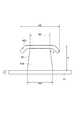
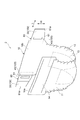
本実施形態では、図1及び2に示す吸収性物品1について説明する。なお、図1及び2においては、吸収性物品1の一例としてオープン型(フラット型)のおむつを挙げているが、固定部材が設けられる吸収性物品は、図1及び2に示すおむつに限定されず、例えば、テープ止め型、パッド型等の他の形態のおむつや、ナプキン、ショーツ一体型ナプキン等の生理用品・衛生用品であってもよい。 In this embodiment, the absorbent article 1 shown in FIGS. 1 and 2 will be described. 1 and 2, an open type (flat type) diaper is cited as an example of the absorbent article 1, but the absorbent article provided with the fixing member is limited to the diaper shown in FIGS. For example, other forms of diapers such as a tape-clamping type and a pad type, and sanitary products and sanitary products such as a napkin and a shorts-integrated napkin may be used.
おむつ(吸収性物品)1は、腹側から背側にかけて着用者の股部を覆うシート状の本体部10を備える。本明細書では、おむつ1の着用者側の面を「内面」といい、その反対側の面を「外面」という。
The diaper (absorbent article) 1 includes a sheet-like
本体部10は、外側シート11と、外側シート11の内側に積層された液体透過性の内側シート12と、外側シート11と内側シート12との間に収容された液体吸収性の高分子吸収体13とを有する。外側シート11は、一般的に、液体不透過性フィルムと不織布層との積層体から構成され、液体不透過性フィルムが高分子吸収体13側、不織布層がおむつ1本体の外面側に存在する。すなわち、おむつ1の着用時に、内側シート12は、おむつ1本体の内面側で着用者の皮膚に隣接して配置され、外側シート11(その不織布層)は、おむつ1本体の外面側で着用者の衣服等に隣接して配置される。ここで、外側シート11に用いられる不織布層としては、例えば、スパンボンド法によって作製されたポリプロピレン不織布を用いることができる。この場合、この不織布層を固定部材との固定に使用することが可能である。
The
腹側端部10aは、本体部10の幅方向(着用時における横方向)に沿って延びる腹側サイドパネル16を含む。また、背側端部10bは、本体部10の幅方向に沿って延びる背側サイドパネル17を含む。本明細書では、いくつかの図に示すように、2種類のサイドパネル16,17の巻付け方向を符号Lで示し、その巻付け方向Lと直交する方向を幅方向Wと定義する。巻付け方向Lはサイドパネル16,17の突出方向と同義である。
The
本体部10の腹側端部10aの外面に、本体部10の幅方向に延びる帯状のループ材14が設けられてもよい。ある態様において、ループ材14は、フックが係合する多数のループ体を有する。あるいは、このようなフックが係合する多数のループ体を有するループ材14に代えて、フックを繊維に係合させることが可能な不織布等をループ材14として使用してもよい。また、ループ材14を設ける代わりに、フックが係合する多数のループ体が設けられた素材により外側シート11の外面層を構成してもよいし、上述のように、フックを繊維に係合させることが可能な不織布等により外側シート11を構成してもよい。
A belt-
巻付け方向Lにおける背側サイドパネル17の端部には、本体部10の腹側端部10aと背側端部10bとを着用者の腰部の左右で着脱自在に連結する一対の固定部材20が、接着、縫い付け、溶着などにより設けられる。本実施形態における固定部材20は「ファスニングタブ」ともいわれる。この固定部材20は、基材21と、その基材21に設けられた第1面ファスナ30とを備える。一方、腹側サイドパネル16の外面には第2面ファスナ40が設けられる。したがって、おむつ1では、固定部材20が第1固定部材であり、背側端部10b及び背側端部10bから本体部10の幅方向に沿って延びる背側サイドパネル17が第1領域であり、腹側サイドパネル16が第2固定部材であり、腹側端部10aが第2領域である。第1面ファスナ30はループ材14または腹側端部10aと係合し、第2面ファスナ40は背側サイドパネル17と係合する。このように、本実施形態におけるファスニングシステム100は、背側サイドパネル17を含む背側端部10bと、腹側サイドパネル16を含む腹側端部10aとを固定するためのシステムであって、背側サイドパネル17から突出する固定部材20に設けられた第1面ファスナ30と、腹側サイドパネル16に設けられた第2面ファスナ40とを備える。固定部材20をループ材14に巻き付けたときには、第2面ファスナ40が背側サイドパネル17に係合し、第1面ファスナ30がループ材14に係合する。したがって、ファスニングシステム100により二つの領域が固定された状態では、第1面ファスナ30より第2面ファスナ40の方が、第1面ファスナ30が設けられた固定部材20の自由端部20aから離れた場所に位置する(図2参照)。ここで、固定部材20の自由端部20aとは、固定部材20の巻付け方向Lにおける端部であり、かつ背側サイドパネル17に取り付けられていない側の端部である。
A pair of fixing
第1面ファスナ30および第2面ファスナ40はともに面ファスナである。面ファスナとは、任意の面の範囲で着脱可能なファスナである。面ファスナはフック材およびループ材の双方を含む概念である。なお、ファスニングシステム100では、第1面ファスナ30と第2面ファスナ40とが互いに係合することは意図しない。本実施形態では、第1面ファスナ30および第2面ファスナ40はともにフック材であるとの前提で以下に説明する。
Both the
基材21は、背側端部10bから本体部10の幅方向に沿って外側に突出し、着用時に腹側端部10aに巻き付いて連結する部分である。この基材21は柔軟性を有する。ここで、柔軟性とは、基材21が、固定部材が適用される領域の表面形状に沿って簡単に曲がって追従可能となるような性質をいう。基材21は伸長性または伸縮性を有してもよいし、弾性的に変形してもよい。なお、弾性的な変形の一部に塑性的な変形が含まれてもよい。固定部材20が吸収物品または衣類に適用される場合、柔軟性とは、着用者がごわごわ感を感じない程度の剛性をいう。なお、基材21の柔軟性の度合いは、固定部材が適用される領域の表面形状、構造、組成、用途等に基づき任意に定めてよい。基材21として不織布を用いた場合には、柔軟性を不織布の坪量で表すことができ、ある態様においては、不織布の坪量が5g/m2以上、10g/m2以上もしくは20g/m2以上であって、600g/m2以下、400g/m2以下もしくは200g/m2以下の範囲であれば、基材21が柔軟性を有すると見ることができる。ある態様においては、不織布の坪量を30g/m2以上、100g/m2以下とすることが好ましい。
The
本実施形態では、基材21は突出方向(巻付け方向)に向かって窄む形状を呈するが、基材21の形状はこれに限定されない。例えば、基材21は矩形状であってもよいし、基材21の外縁の少なくとも一部が円弧であってもよい。
In this embodiment, although the
基材21の材料は、固定部材が適用される領域に対する基材21の柔軟性の観点から適宜選択される。例えば、織布、不織布、プラスチック・フィルム、あるいはこれらの混合により基材21を作製してもよい。基材21は外側シート11および背側サイドパネル17と同じ材料により作製されてもよく、この場合には基材21、外側シート11、および背側サイドパネル17が一体成形されてもよい。あるいは、エラストマー成形体と伸縮性を有する繊維集合体との積層体により、伸縮性を有する基材21を作製してもよい。エラストマー成形体と繊維集合体とは接着剤や熱融着などにより接合されてもよいし、編んだり縫ったりする等の物理的方法により接合されてもよい。
The material of the
エラストマーの例として熱可塑性エラストマーが挙げられる。この熱可塑性エラストマーはハードセグメントとソフトセグメントとからなり、主にハードセグメントが分子拘束の機能を有する。熱可塑性エラストマーは、そのハードセグメントの種類により分類することができる。熱可塑性エラストマーの例として、スチレン系熱可塑性エラストマー、オレフィン系熱可塑性エラストマー(TPO)、塩ビ系熱可塑性エラストマー、ウレタン系熱可塑性エラストマー、エステル系熱可塑性エラストマー、アミド系熱可塑性エラストマーなどが挙げられる。エラストマー成形体は一種類の熱可塑性エラストマーのみから成るものであってもよいし、2種以上の熱可塑性エラストマーの混合物であってもよい。エラストマー成形体は更に、各種の添加剤(タッキファイヤー(粘着性付与剤)、酸化防止剤、耐候剤、紫外線吸収剤、着色剤、無機充填材、オイル等)を含んでもよい。 An example of the elastomer is a thermoplastic elastomer. This thermoplastic elastomer is composed of a hard segment and a soft segment, and the hard segment mainly has a molecular constraint function. Thermoplastic elastomers can be classified according to their hard segment type. Examples of thermoplastic elastomers include styrenic thermoplastic elastomers, olefinic thermoplastic elastomers (TPO), vinyl chloride thermoplastic elastomers, urethane thermoplastic elastomers, ester thermoplastic elastomers, and amide thermoplastic elastomers. The elastomer molded body may be composed of only one kind of thermoplastic elastomer, or may be a mixture of two or more kinds of thermoplastic elastomers. The elastomer molded body may further contain various additives (tackifier (tackifier), antioxidant, weathering agent, ultraviolet absorber, colorant, inorganic filler, oil, etc.).
繊維集合体は例えば不織布である。繊維集合体の材料について特に制限はなく、従来から知られている種々の繊維材料を使用することができる。繊維集合体の伸縮性、柔らかさ、及び肌触りの良さを得るための材料の例として、ポリプロピレン繊維、ポリエステル繊維とポリオレフィン繊維とを混紡した混合繊維、ポリエチレンテレフタレートの芯材をポリエチレンで覆った同心型複合繊維、ポリプロピレンの芯材をポリエチレンで覆った同心型複合繊維などが挙げられる。繊維集合体の製造方法に関しても特に制限はなく、スパンボンド法、スパンレース法、サーマルボンド法、メルトブローン法、ニードルパンチ法などのような周知の様々な製造方法を用いることができる。 The fiber assembly is, for example, a nonwoven fabric. There is no restriction | limiting in particular about the material of a fiber assembly, Various conventionally well-known fiber materials can be used. Examples of materials for obtaining the elasticity, softness, and softness of the fiber assembly include polypropylene fiber, mixed fiber in which polyester fiber and polyolefin fiber are blended, and concentric type with polyethylene terephthalate core covered with polyethylene. Examples include composite fibers and concentric composite fibers in which a polypropylene core material is covered with polyethylene. There are no particular limitations on the method for producing the fiber assembly, and various known production methods such as a spunbond method, a spunlace method, a thermal bond method, a melt blown method, a needle punch method and the like can be used.
基材21の厚さは、固定部材が適用される領域に対する基材21の柔軟性の観点から適宜選択される。例えば、その厚さの下限は50μm、70μm、または100μmでもよく、その厚さの上限は500μm、400μm、または300μmでもよい。基材21の広さも、固定部材が適用される領域に対する基材21の柔軟性の観点から適宜選択してよい。例えば、基材21の巻付け方向Lにおける最大長は30mm以上でもよく、300mm以下、または250mm以下でもよい。また、基材21の幅方向Wにおける最大長は10mm以上でもよく、200mm以下または150mm以下でもよい。
The thickness of the
第1面ファスナ30は、基材21の内面に、接着、縫い付け、溶着などにより取り付けられる。図1に示されるように、本実施形態では基材21の先端部が第1面ファスナ30により覆われず、この先端部は、第1面ファスナ30がループ材14に接合された状態でも容易につまむことが可能なつまみ部21aとして機能する。もっとも、基材21の先端まで第1面ファスナ30が存在してもよい。また、第1面ファスナ30は、基材21の内面全体を覆ってもよい。
The
第1面ファスナ30の全体形状については、ずれに対する固定部分の安定性、および被固定部材の動きに対する当該固定部分の追従性の観点から適宜選択される。第1面ファスナ30の全体形状の例として、矩形状、円状、長円状、楕円状、多角形状、またはそれらを組み合わせた形状が挙げられる。
About the whole shape of the
本実施形態において、第1面ファスナ30は、例えば茸状の複数のフック体を有する。複数のフック体は、例えば約60〜約1550個/cm2の密度で形成されてもよいし、約125〜約690個/cm2の密度で形成されてもよいし、約248個/cm2の密度で形成されてもよい。各フック体の高さは、約30〜約1270μmでもよいし、約100〜約510μmでもよいし、約180〜約330μmでもよい。
In the present embodiment, the
各フック体の茎部の直径は、例えば約76〜約635μmでもよいし、約127〜約305μmでもよい。各フック体の傘部は、例えば円板形状を呈する。茎部の外周面からの傘部の張り出し量は、例えば約13〜約254μmでもよいし、約25〜約127μmでもよいし、約120μmでもよい。傘部の厚さは、例えば約13〜約254μmでもよいし、約25〜約127μmでもよい。傘部の平面形状は、円形状に限られず、楕円形状や多角形状であってもよい。各フック体を除外した第1面ファスナ30の厚さ、すなわち各フック体を支持する第1面ファスナ30のシート部分の厚さは、約25〜約512μmでもよいし、約64〜約254μmでもよい。
The diameter of the stem portion of each hook body may be, for example, about 76 to about 635 μm, or about 127 to about 305 μm. The umbrella part of each hook body has a disk shape, for example. The protruding amount of the umbrella part from the outer peripheral surface of the stem part may be, for example, about 13 to about 254 μm, about 25 to about 127 μm, or about 120 μm. The thickness of the umbrella part may be, for example, about 13 to about 254 μm, or about 25 to about 127 μm. The planar shape of the umbrella portion is not limited to a circular shape, and may be an elliptical shape or a polygonal shape. The thickness of the
一方、第2面ファスナ40の全体形状も、ずれに対する固定部分の安定性、および被固定部材の動きに対する当該固定部分の追従性の観点から適宜選択される。第2面ファスナ40の全体形状の例として、矩形状、円状、長円状、楕円状、多角形状、またはそれらを組み合わせた形状が挙げられる。
On the other hand, the overall shape of the
第2面ファスナ40の設置範囲は任意に定めてよい。本実施形態において、第2面ファスナ40は背側サイドパネル17の内面に係合するので、第2面ファスナ40は、背側サイドパネル17の領域に収まる程の寸法を有してもよい。この場合には、腹側端部10aと背側端部10bとを固定した時に第2面ファスナ40を背側サイドパネル17で完全に隠すことができる。あるいは、腹側端部10aと背側端部10bとを固定した時に第2面ファスナ40の一部が背側サイドパネル17から露出してもよい。
The installation range of the
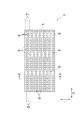
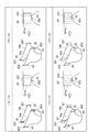
第2面ファスナ40の具体的な態様を図3〜20に示す。図3はフックの例を示す。図4は、溝も貫通部も形成されない第2面ファスナ40の例である。図5〜18は、溝または貫通部が形成された第2面ファスナ40の例を示す。より具体的には、図5〜13は、複数のスリット状の溝または貫通部が形成された第2面ファスナ40の例を示し、図14〜18は、スリット状以外の形状の貫通部(開口部)が形成された第2面ファスナ40の例を示す。本明細書では、隣り合う溝または貫通部で挟まれた細長いフック材領域をストランドという場合がある。なお、図4以降では、図3に示すフック42を簡略化して表している。図19は開口部を形成する手法の一例を示す。図20は、複数の第2面ファスナ40を間隔を空けて設ける例を示す。
Specific modes of the
図4に示すように、スリット状の溝または貫通部も開口部も有しないフックを第2面ファスナ40として使用することができる。これらの溝、貫通部、および開口部が形成されていない場合、第2面ファスナ40の厚さは、一般的に、60〜380μmの範囲で設定される。ずれに対する固定部分の安定性、および被固定部材の動きに対する当該固定部分の追従性の観点から、ある態様においては、下限を90μmまたは115μmとすることができ、上限を350μmまたは320μmとすることができる。本明細書では、60〜380μmという厚さの条件を満たす面ファスナを「薄型面ファスナ(low-profile fastener)」ともいう。剛性が小さい薄型面ファスナを第2面ファスナ40として用いることで第2面ファスナ40自体が柔軟に変形するので、溝、貫通部、または開口部を形成しなくても、第2面ファスナ40が設けられた領域の剛性を低く抑えることができる。
As shown in FIG. 4, a slit-like groove or a hook having no through portion and no opening can be used as the
第2面ファスナ40は、シート状のベース41と、そのベース41表面に設けられた多数のフック42とを備える。図3に示すように、本実施形態では、フック42はベース41から延びる茎部42aと、その茎部42aの先端に形成された傘部42bとを備え、全体として茸状を呈する。なお、フック42における傘部42bの形状としては、係合力を満足できるものであれば種類を問わないが、例えば、上記した茸状以外にも、鉤状、T字状、J字状のものが使用できる。
The
図4に示す第2面ファスナ40を用いる場合、図3に示す第2面ファスナ40の厚さ及び高さは、ずれに対する固定部分の安定性、および被固定部材の動きに対する当該固定部分の追従性の観点から、例えば以下のように設定することができる。
When the
ベース41の厚さtの下限は20μm、30μm、または35μmでもよく、その厚さtの上限は80μm、70μm、または60μmでもよい。 The lower limit of the thickness t of the base 41 may be 20 μm, 30 μm, or 35 μm, and the upper limit of the thickness t may be 80 μm, 70 μm, or 60 μm.
フック42の高さhの下限は40μm、60μm、または80μmでもよく、その高さhの上限は300μm、280μm、または260μmでもよい。
The lower limit of the height h of the
茎部42aの底の最大幅wa及び茎部42aの先端の幅wcについては、所望の係合力が得られるのであれば、その幅に、特に制限はない。図3に示すような茸状のフック材を例にとると、茎部42aの底の最大幅waの下限は70μmまたは100μmであってもよく、その最大幅waの上限は250μm、200μm、または190μmであってもよい。茎部42aの先端の幅wcの下限は50μmまたは80μmであってもよく、その幅wcの上限は200μm、195μm、または185μmであってもよい。
The maximum width wa at the bottom of the
また、傘部42bの最大幅wbについても、係合力の観点から、適宜その幅について定めることができる。図3に示されるように、傘部42bの最大幅wbは茎部42aの底の最大幅waよりも大きいことが好ましく、傘部42bの最大幅wbと茎部42aの底の最大幅waとの比の上限は1.01:1、2:1、または3:1であってもよい。その最大幅wbの下限は70μmまたは100μmであってもよく、最大幅wbの上限は350μmまたは340μmであってもよい。茎部42aの先端からの傘部42bの張出し量pの下限は5μmでも10μmでもよく、その張出し量pの上限は90μm、85μm、80μm、または75μmであってもよい。
Further, the maximum width wb of the
上記のベース41の厚さ及びフック42の高さに基づくと、第2面ファスナ40全体の厚さの下限は60μm、90μm、または115μmでもよく、その厚さの上限は380μm、350μm、または320μmでもよい。この第2面ファスナ40全体の厚さは、その第2面ファスナ40が取り付けられる領域の柔軟性を考慮して設定される。
Based on the thickness of the
また、ある態様においては、例えば、第2面ファスナ40が設けられる領域の厚さに対する第2面ファスナ40の厚さの比(領域厚さ/面ファスナ厚さ)の下限を0.02、0.03、または0.05とすることができ、その比の上限を7.6、5、または3.2とすることができる。ここで、第2面ファスナ40が設けられる領域の厚さとは基材の厚さのことであり、本実施形態では、腹側サイドパネル16の基材の厚さである。
In one embodiment, for example, the lower limit of the ratio of the thickness of the
一方、図5〜18に示すように第2面ファスナ40に溝、貫通部、または開口部を設けるのであれば、薄型面ファスナを第2面ファスナ40として用いてもよいし、第1面ファスナ30と同様に、厚さが380μmを超える面ファスナを用いてもよい。
On the other hand, as shown in FIGS. 5 to 18, a thin surface fastener may be used as the
ここで、本明細書における用語「溝」は、切込みが第2面ファスナ40におけるフック42側のベース41表面に設けられ、かつフック42とは反対側のベース41表面に貫通しない状態を示す。本実施形態では、スリット状の溝43bを指すが、その用語が網羅する範囲はこれに限定されない。例えば、「溝」は、線状ではなく二次元(面)状に広がる凹みも含む概念である。
Here, the term “groove” in the present specification indicates a state in which the notch is provided on the surface of the base 41 on the
また、本明細書における用語「貫通部」は、第2面ファスナ40に設けられた孔または開口が、フック42側のベース41表面から、フック42とは反対側のベース41表面まで貫通した状態を示す。本実施形態では、スリット状の貫通部43a、及びスリット状以外の形状の貫通部(すなわち、開口部44)を指すが、その用語が網羅する範囲は限定されない。例えば、「貫通部」は、第2面ファスナ40に設けられた点状の孔、直線以外の波型、山形、凹凸型の貫通したスリットも含む概念である。
In addition, the term “penetrating portion” in the present specification refers to a state in which a hole or opening provided in the
図6(b)に示すように、スリット状の溝43bは第2面ファスナ40の一方の面、すなわちフック42側のベース41表面にのみ形成され、フック42側の反対側の面までは到達しない。これに対して、図6(a)に示すようなスリット状の貫通部43a、図14〜18に示すような開口部44は、面ファスナの一方の面から他方の面にかけて開口が形成される。また、図6(c)、図13(c)、図15に示すように、第2面ファスナ40において、溝と貫通部の両方が存在していてもよい。
As shown in FIG. 6B, the slit-shaped
溝及び貫通部43は、従来から用いられている任意の手法により形成することができる。例えば、スリット状の溝43bや貫通部43aは、刃やレーザ切断などにより、それぞれ、フック42側のベース41表面からベース41の一定の厚さまで、及びフック42側のベース41表面からフック42側の反対側の面に亘って形成される。一方、貫通部の他の例である開口部44は、例えば、スリット状の貫通部43aが形成された第2面ファスナ40をスリット列と直交する方向に広げることで形成することができる。また、開口部44は、第2面ファスナ40を所望の形にくり抜くことで、第2面ファスナ40を広げることなく形成してもよい。なお、スリット状の貫通部43aを形成し、基材に第2面ファスナ40を貼り付けた後に当該基材と一緒にスリット状の貫通部43aを拡げることで、開口部44を形成してもよい。第2面ファスナ40を広げる手段としては、幅出し機(tenter)やローラなどの機械や、手作業などが挙げられる。開口部を形成する際の第2面ファスナ40の伸長率は限定されず、その上限は例えば50%、100%、150%、200%、300%、400%または600%であってもよい。ここで、伸長率は、第2面ファスナ40における、貫通部を拡げることで開口部を形成する方向(図19における伸長方向)の元々の長さ(初期長さ)に対して、どの程度伸長させたか、を示したものである。すなわち、伸長率50%とは、第2面ファスナ40の長さが初期長さに対して1.5倍になっていることを、伸長率100%とは、第2面ファスナ40の長さが初期長さに対して2倍になっていることを、伸長率200%とは、第2面ファスナ40の長さが初期長さに対して3倍になっていることを、それぞれ表わす。
The groove and the through
全体の厚さが上記のように設定された薄型面ファスナを第2面ファスナ40として用いた場合には、第2面ファスナ40の剛性が小さくなり、第2面ファスナ40自体が柔軟に変形するようになる。また、第2面ファスナ40に溝または貫通部43を形成することによって第2面ファスナ40の剛性を下げることができるので、第2面ファスナ40自体が柔軟に変形するようになる。したがって、柔軟性を有する領域にその第2面ファスナ40を取り付けたとしても、当該領域の全体として柔軟性を維持することができる。その結果、固定部分の柔軟性が上がり、その固定部分が被固定部材の動きなどに追従できるようになるので、腹側端部10aと背側端部10bとを固定した場合に固定部材20がループ材14または腹側端部10aから剥がれにくくなる。また、薄型面ファスナにより形成された第2面ファスナ40、あるいは溝または貫通部43を有する第2面ファスナ40は柔らかいので、ごわつかず、第2面ファスナ40を吸収性物品や衣類等に取り付けた場合には着用者の肌に与える刺激を低減させることができる。よって、このような第2面ファスナ40を使用することで、吸収性物品の使い勝手をより高めることが可能になる。
When a thin surface fastener having an overall thickness set as described above is used as the
図5の例では、スリット状の溝または貫通部列Rs(以下、スリット列Rsという場合もある)は、第2面ファスナ40の幅方向Wに沿った各フック列Rhの間に、隣り合うスリット列Rsで各フック列Rhを挟み込むように形成されている。したがって、この例では、フック列Rhから構成されるストランド45の幅方向(第2面ファスナ40における巻付け方向L)におけるフック42の個数は1であり、言い換えれば、各ストランド45の幅はフック42の1個分(正確には、フック42の1個分及びフック42から続く一定長さのベース41部分)に相当する。各スリット列Rsにおいて、複数のスリット状の溝または貫通部43が一定の間隔をおいて形成されており、図5〜11、図14〜18における実施形態では、その間隔に相当する領域(ベース41がそのままの状態で残っている領域)を中継部46という。図5の例では、中継部46が千鳥状に並んでいる。
In the example of FIG. 5, slit-like grooves or penetrating portion rows Rs (hereinafter also referred to as slit rows Rs) are adjacent to each other between the hook rows Rh along the width direction W of the
図6に示すように、スリット状の溝または貫通部43に関し、図6(a)の例ではすべてのスリットがベース41を貫通しており、スリット状の貫通部43aが形成されている。また、図6(b)の例ではすべてのスリットが溝であり、フック42が存在するベース41表面から一定深さを有する、スリット状の溝43bが形成されている。更に、図6(c)の例のように、ベース41を貫通したスリット状の貫通部43aと溝状のスリット状の溝43bとが交互に配されていてもよい。スリット43が溝である場合には、ベース41の厚さに対するスリット43の深さの比の下限は0.4でもよく、その比の上限は0.9でもよい。
As shown in FIG. 6, with respect to the slit-like groove or penetrating
ストランド45の幅は限定されない。例えば、図7に示すようにストランド45の幅がフック42の2個分であってもよいし、3個以上のフック42に相当してもよい。ストランド45の最大幅はフック42の10個分であってもよい。
The width of the
第2面ファスナ40に設けられるスリット列Rsの間隔も限定されない。例えば、スリット列Rsと直交する方向において、1cm当たりのスリット列Rsの個数の下限は1でもよく、その個数の上限は10でもよい。
The interval between the slit rows Rs provided in the
スリット状の溝または貫通部43が延びる方向も限定されない。例えば、図8に示すように各スリット列Rsが巻付け方向Lに沿って延びていてもよい。あるいは、各スリット列Rsは巻付け方向Lまたは幅方向Wに対して任意の角度θ(0°<θ<90°)で傾斜していてもよい。
The direction in which the slit-like groove or the through
ストランド45の幅は不均一でもよい。例えば図9に示すように、一方の端部に向かってストランド45の幅が次第に狭くなっていくようにスリット43を形成してもよい。あるいは図10に示すように、一つのフック列Rhのみを含むストランド45と、二つのフック列Rhを含むストランド45とが混在していてもよい。
The width of the
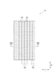
中継部46の配置は、図5に示すような千鳥状に限定されない。例えば図11に示すように、隣り合う任意の中継部46が、スリット列Rsと直交する方向(図11では方向L)に沿って並んでいてもよい。
The arrangement of the
図12に示すように、一本のスリット状の溝または貫通部43が第2面ファスナ40の一辺からその対辺にかけて途切れることなく延びていてもよい。この場合には中継部46は第2面ファスナ40上に存在しないことになる。この場合、スリット列Rsの態様としては、図13(a)に示すように、すべてのスリットがベース41を貫通し、スリット状の貫通部43aが形成されてもよいし、図13(b)のように、すべてのスリットが溝であり、フック42が存在するベース41表面から一定深さを有する、スリット状の溝43bが形成されてもよい。更に、図13(c)の例のように、ベース41を貫通したスリット状の貫通部43aと溝状のスリット状の溝43bとが交互に配されてもよい。スリット43が溝である場合には、ベース41の厚さに対するスリット43の深さの比の下限は0.4でもよく、その比の上限は0.9でもよい。
As shown in FIG. 12, one slit-like groove or penetrating
スリット状の溝または貫通部43の長さは任意に設定してよい。例えば、各スリット状の溝または貫通部43の長さの下限は8mm、10mmまたは12mmであってもよい。あるいは、スリット列Rsに沿った第2面ファスナ40の長さに対する、該スリット列Rs内のスリット状の溝または貫通部43の長さの合計の比(スリット状の溝または貫通部長さの合計/スリット列Rsの長さ)で、スリット状の溝または貫通部43を規定することができる。例えば、その比は40%以上または50%以上とすることができる。
The length of the slit-like groove or the through
中継部46の長さも任意に設定してよい。例えば、中継部46の長さの下限は0.25mm、0.5mm、または0.75mmでもよく、その長さの上限は10mm、15mm、または20mmでもよい。
The length of the
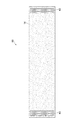
図14は、開口部44が設けられた第2面ファスナ40を示している。図14に示す開口部44は、第2面ファスナ40の幅方向Wに沿って延びるスリットを巻付け方向Lに広げることで形成されたものである。この例では、各ストランド45の幅はフック42の1個分に相当し、開口部44及び中継部46はそれぞれ千鳥状に並んでいる。
FIG. 14 shows the
図14の例では開口部44が略菱形であるが、開口部の形状はこれに限定されない。例えば、開口部は六角形であってもよく、そのような開口部が千鳥状に並んだ場合には第2面ファスナ40はハニカム構造であるといえる。あるいは、開口部は円形、楕円形、矩形、星形、波形、あるいは他の多角形であってもよい。
In the example of FIG. 14, the
図15に示すように、複数のスリットの一部のみを広げることで、開口部44及びスリット状の溝または貫通部43の双方が存在する第2面ファスナ40を用意してもよい。この例では開口部44が第2面ファスナ40の中央部に設けられ、スリット状の溝または貫通部43が両端付近に設けられているが、スリット状の溝または貫通部43及び開口部44の位置はこれに限定されない。例えば、スリット状の溝または貫通部43が中央部に設けられ、開口部44が両端付近に設けられてもよい。
As shown in FIG. 15, the
図16に示す開口部44は、方向Lに沿って延びるスリットを広げることで形成されたものである。このように、開口部の基となるスリット状の貫通部43の延びる方向は限定されない。
The
貫通部として開口部44を採用した場合でも、スリット状の溝または貫通部43の場合と同様に、ストランド45の幅は限定されない。例えば、各ストランド45の幅は2個分のフック42に相当するものであってもよいし、その幅の最大値は10個分のフック42に相当するものであってもよい。ストランド45の幅は均一でなくてもよく、例えば図17のように、一方の端部に向かってストランド45の幅が次第に狭くなっていくように開口部44を形成してもよい。
Even when the
開口部44の大きさは均一である必要なく、例えば図18や上記図17に示すように開口部44の大きさが不均一であってもよい。また、図18の例のように開口部44の形状が様々であってもよい。
The size of the
開口部44が形成された第2面ファスナ40に関しても、中継部46は千鳥状に配されていなくてもよい。例えば、図11の例と同様に中継部46が格子状に並んでいてもよい。
Also with respect to the
開口部44が形成された第2面ファスナ40を接着剤または粘着剤により基材に貼り付けた際には、その接着剤または粘着剤が開口部44から露出してもよい。
When the
基材に取り付けられる、溝または貫通部が形成されたフック材におけるフック42の密度について説明する。かかるフック密度は、「フック材におけるフック総本数/フック材におけるベース41及び開口部44の総面積」から求められる。なお、複数の第2面ファスナ40を基材に間隔をあけて設置した場合には、複数の第2面ファスナ40間に存在する隙間面積は前記総面積に含めない。基材21上におけるフック42の密度の下限は、例えば約31個/cm2、約39個/cm2とすることができる。また、その密度の上限は、例えば約1550個/cm2、約1240個/cm2であってもよい。例えば、その密度は約465個/cm2でもよい。
The density of the
スリット状の貫通部43が形成された第2面ファスナ40を広げることで開口部44を形成し、その形成された開口部44の形状を維持したまま第2面ファスナ40を基材に取り付ける場合において、広げる前の第2面ファスナ40におけるフック42の初期密度を以下のように設定してもよい。すなわち、その初期密度の下限は例えば50個/cm2、70個/cm2、または100個/cm2であってもよく、その初期密度の上限は例えば1550個/cm2でもよい。なお、フック42の初期密度は、「フック材におけるフック総本数/拡げる前のフック材におけるベース41の総面積」から求められる。なお、複数の第2面ファスナ40を基材に間隔をあけて設置した場合には、その第2面ファスナ40のそれぞれを上記初期密度の範囲とすることができる。
When the
また、第2面ファスナ40が基材に取り付けられた際の、第2面ファスナ40全体の面積に対する傘部42b表面の面積の合計値の割合(傘部の相対密度)の下限は、例えば5%でも10%でもよい。その割合の上限は例えば24%、30%、または40%でもよい。なお、複数の第2面ファスナ40を基材に設置した場合には、その第2面ファスナ40のそれぞれを上記割合の範囲とすることができる。
Moreover, when the
図20に示すように基材(腹側サイドパネル16)上に複数の第2面ファスナ40を間隔を空けて設ける場合にも、薄型面ファスナを第2面ファスナ40として用いてもよいし、第1面ファスナ30と同様に、厚さが380μmを超える面ファスナを用いてもよい。この場合には、その間隔が、上述したスリット状の溝または貫通部、あるいは開口部に相当する役割を果たすので、それぞれの第2面ファスナ40にスリット状の溝または貫通部、あるいは開口部を形成しなくてもよい。もちろん、それぞれのまたは一部の第2面ファスナ40にスリット状の溝または貫通部、あるいは開口部が形成されてもよい。腹側サイドパネル16上に複数の第2面ファスナ40を設ける場合には、それぞれの第2面ファスナ40の形状は同一であってもよいし異なってもよい。
As shown in FIG. 20, a thin surface fastener may be used as the
第2面ファスナ40は、例えば熱可塑性樹脂によって形成される。まず、多数の貫通孔を有する型板またはダイスを用いた押出成形により、複数のフックの原形をなす複数の柱状体が表面に並んだシート材を形成する。次に、各柱状体の先端部を加熱して、例えば、円板状に潰すことで傘部42bを有する各フック42を形成し、第2面ファスナ40を得る。熱可塑性樹脂としては、例えば、ポリエチレンやポリプロピレンなどのポリオレフィン、ポリエチレンテレフタレート、ナイロン等のポリアミド、ポリ(スチレン−アクリロニトリル)、ポリ(アクリロニトリル−ブタジエン−スチレン)、可塑化塩化ビニル、ポリエステル等が挙げられる。これらの熱可塑性樹脂の1種のみを用いてもよいし、2種以上の熱可塑性樹脂を混合したポリマーブレンドを用いてもよい。また、ポリエチレンとポリプロピレンとのコポリマーを用いてもよい。
The
図3〜20を用いて説明した第2面ファスナ40を基材に取り付けることで、第2面ファスナ40を備える固定部材の曲げ剛性を小さくすることができる。上述した通り、第2面ファスナ40を備える固定部材における、基材と該基材に積層された第2面ファスナ40との積層体部分の曲げ剛性Saと、その基材とJIS Z 1522に規定されたセロハン粘着テープ(比較用テープ)との積層体である比較用部材の曲げ剛性Sbとの比を求めることで、第2面ファスナ40の柔軟性を示す。第2面ファスナ40を含む固定部材の曲げ剛性と比較用部材の曲げ剛性とを比較する場合において、基材の条件は同じにする。以下では、曲げ剛性の測定に用いる固定部材の積層体部分と、比較用部材となる積層体とをまとめて試験片ともいう。固定部材の積層体部分から得られる試験片では、基材の一方の面の全体を第2面ファスナ40が覆い、比較用部材となる積層体では基材の一方の面の全体を比較用テープが覆う。
By attaching the
一例として、図1に示すおむつ1から、曲げ剛性を測定するための試験片を得る方法を説明する。まず、基材と該基材に積層された第2面ファスナ40とを含む積層体部分(固定部材における基材と第2面ファスナ40との積層体)は、腹側サイドパネル16のうち第2面ファスナ40が積層された部分を切り取ることで得られる。一方、比較用部材は、腹側サイドパネル16のうち第2面ファスナ40が積層されていない部分から基材を切り出し、その基材に比較用テープを積層し積層体とすることで得られる。比較用テープは、基材の外面および内面のうち、第2面ファスナ40が積層された側と同じ面に貼られる。試験片の寸法は、測定装置の種類または取得可能な試験片の寸法を考慮して決めればよい。試験片は、基材の一方の面の全体を第2面ファスナ40または比較用テープが覆う態様で用意される。
As an example, a method for obtaining a test piece for measuring bending stiffness from the diaper 1 shown in FIG. 1 will be described. First, a laminated body portion (a laminated body of the base material and the
次に、曲げ剛性の測定方法を説明する。本明細書における用語「曲げ剛性」は、TAPPIT543 om−11に規定された方法に従って、ガーレ式試験機を用いた片持ちばりの曲げ試験によって測定される曲げ剛性を意味する。この方法によって測定される曲げ剛性は、当業者によって「ガーレ剛性」(Gurley Stiffness)と称される場合がある。曲げ試験は、温度23℃、相対湿度50%の環境下で行われる。 Next, a method for measuring the bending stiffness will be described. The term “bending stiffness” in the present specification means the bending stiffness measured by a cantilever bending test using a Gurley type tester according to the method defined in TAPIT 543 om-11. The bending stiffness measured by this method may be referred to as “Gurley Stiffness” by those skilled in the art. The bending test is performed in an environment at a temperature of 23 ° C. and a relative humidity of 50%.
図21は、曲げ剛性(ガーレ剛性)を測定するための曲げ試験の方法を示す図である。図21に示すように、試験片(固定部材の積層体部分、または比較用部材)の一方の端部が、つかみ具210によって挟持される。つかみ具210が回転軸220のまわりを回転することで、試験片300は回転軸220のまわりの周方向Aに沿って移動する。板状部材225は、回転軸(支点)220のまわりを回転自在に設けられた振子の軸222の一方の先端に設けられており、軸222には、おもり228が取り付けられている。おもり228の質量及び取り付けの位置は、試験片300の曲げ剛性の程度等に応じて適宜選択される。
FIG. 21 is a diagram illustrating a bending test method for measuring bending rigidity (Gurley rigidity). As shown in FIG. 21, one end of a test piece (a laminated body portion of a fixing member or a comparison member) is held by a
試験片300が周方向A(時計回り)に沿って一定の速度で移動したときに、試験片300の自由端側の端部が板状部材225に当たることで、試験片300が曲げられる。試験片300が移動を続けると、板状部材225は試験片300に押されてある程度回転したところで、試験片300から解放される。この過程において板状部材225が受ける最大荷重に基づいて、曲げ剛性が求められる。その後、試験片300を反対方向(反時計回り)に移動させることで、試験片300が反対側に向けて曲げられたときの曲げ剛性を測定することができる。試験片の移動速度は、2回/minに設定される。曲げ剛性は、試験片300が周方向を往復して測定される2個の測定値の平均値として求められる。
When the
図22は、この曲げ試験のための試験片300の固定位置を示す。試験片300はストリップ状である。試験片300が挟持される表裏の向きは、任意である。つかみ具210から回転軸220へと向かう方向L´に沿った試験片300全体の長さは、例えば25.4±0.4mm(0.25±1/64インチ)に設定される。試験片300のうち、つかみ具210が挟持する部分のL‘方向の長さは6.35mmに設定され、自由端からL12の長さの部分が、板状部材225に当てられる。長さL12は、6.35mm(0.25インチ)に設定される。一方、方向L´に直交する方向W´における長さ(幅)W11は、25.4±0.4mm(1±1/64インチ)又は12.7±0.4mm(0.5±1/64インチ)である。なお、方向L´と巻付け方向Lとが一致するとは限らず、方向W´と幅方向Wとが一致するとも限らない。
FIG. 22 shows a fixed position of the
上述した通り、基材と該基材に積層された第2面ファスナ40との積層体部分の曲げ剛性Saと、比較用部材の曲げ剛性Sbとの間には、Sa/Sb<2.0という関係が成立する。あるいは、Sa/Sbは1.7以下でもよいし、1.6以下でもよいし、1.5以下でもよいし、1.1以下でもよい。ある態様においては、Sa/Sbは、1.0以下でもよいし、0.9以下でもよいし、0.8以下でもよいし、0.7以下でもよい。また、別の態様においては、Sa/Sbは、0.6以下、あるいは0.5以下とすることもできる。具体的には、図4に示すように第2面ファスナ40に溝も貫通部も開口部も形成されない場合には、Sa/Sbは1.7以下でもよいし、1.6以下でもよいし、1.5以下でもよいし、1.1以下でもよい。第2面ファスナ40に溝、貫通部、または開口部が形成される場合には、Sa/Sbは1.0以下でもよいし、0.9以下でもよいし、0.8以下でもよいし、0.7以下でもよい。薄型面ファスナを用いた第2面ファスナ40に溝、貫通部、または開口部が形成される場合には、Sa/Sbは0.6以下でもよいし、0.5以下でもよい。
As described above, Sa / Sb <2.0 between the flexural rigidity Sa of the laminate portion of the base material and the
以上、第2面ファスナ40について説明した。一方、第1面ファスナ30については、上述した通り、任意の厚さの面ファスナを用いてよい。あるいは、図5〜20に示すものと同様の面ファスナを第1面ファスナ30として用いてもよい。すなわち、第1面ファスナ30は第2面ファスナ40と同様の特徴を有してもよい。
The
第2面ファスナ40は単独で提供されてもよいし、任意の基材に取り付けられた固定部材の態様で提供することも可能である。本明細書では、任意の基材に第2面ファスナ40が取り付けられた固定部材のうち、特に、単独で取引され得る物品を「固定用部品」という。固定用部品の一例を図23に示す。この固定用部品50は、帯状のループ材14と、そのループ材14の長手方向の両端に取り付けられた二つの第2面ファスナ40とを備える。すなわち、固定用部品50ではループ材14を基材として用いる。固定用部品に用いる基材は、上記の基材21と同様に、織布、不織布、プラスチック・フィルム、あるいはこれらの混合であってもよい。当然ながら、固定用部品に用いる第2面ファスナ40の構造も限定されず、図4〜20に示すような構造が採用されてもよい。あるいは、第2面ファスナ40は第1面ファスナ30と共に固定部材に設けられ、固定用部品として提供されてもよい。
The
以下、実施例に基づいて本発明を具体的に説明するが、本発明はそれらに何ら限定されるものではない。 EXAMPLES Hereinafter, although this invention is demonstrated concretely based on an Example, this invention is not limited to them at all.
(実施例1)
帯状のスパンボンド不織布(Toray advanced materials Korea, Inc.製。長さ:100mm、幅:25mm、坪量:30g/m2)を基材として用意するとともに、製品名が「KJ−7891」であるフック材(坪量:100g/m2。ベース厚み:85μm。フックの初期密度:1600ピン/平方インチ(なお、「平方インチ(inch2)」は25.4mm四方に相当する)。楕円形の傘部を有するフックの当該楕円の長軸方向に沿った傘部の長さ(図3における最大幅wbに相当):420μm)を用意した。そして、これらの基材およびフック材を用いてサンプルを生成した。このサンプルは6個用意し、以下ではこれらのサンプルを1〜6の番号を用いて区別する。
Example 1
A band-like spunbonded nonwoven fabric (manufactured by Toray advanced materials Korea, Inc., length: 100 mm, width: 25 mm, basis weight: 30 g / m 2 ) is prepared as a base material, and the product name is “KJ-7891”. Hook material (basis weight: 100 g / m 2, base thickness: 85 μm, hook initial density: 1600 pins / in 2 (“in 2 ” is equivalent to 25.4 mm square). The length of the umbrella portion (corresponding to the maximum width wb in FIG. 3) along the major axis direction of the ellipse of the hook having the umbrella portion was prepared. And the sample was produced | generated using these base materials and hook materials. Six samples are prepared. In the following, these samples are distinguished using numbers 1 to 6.
各サンプルの詳細は以下の通りである。サンプル1ではスリット状の貫通部を形成することなく、用意したフック材をそのまま基材に固定した。サンプル2ではスリット状の貫通部が形成されたフック材を、その貫通部を広げることなくそのまま基材に固定した。サンプル3〜6では、図19に示すように、スリット列と直交する方向(図19における伸長方向)にフック材を所定の割合だけ広げて開口部を設け、その開口部を維持したままフック材を基材に固定した。サンプル3〜6におけるフック材の伸長率はそれぞれ、5%、10%、50%、および80%とした。言い換えれば、サンプル3〜6におけるフック材を基材に固定する際には、フック材の長さをそれぞれ、1.05倍、1.1倍、1.5倍、および1.8倍に伸ばした。サンプル2〜6に関しては、スリットが基材の長手方向に沿って延びるものと、幅方向に沿って延びるものとを用意した。
Details of each sample are as follows. In Sample 1, the prepared hook material was directly fixed to the base material without forming a slit-shaped through portion. In sample 2, the hook material in which the slit-shaped through portion was formed was fixed to the substrate as it was without widening the through portion. In
このように用意したサンプル1〜6の柔軟性を東洋精機社製のロードセルによりループ・スティフネスを測定することで確認した。この測定では、サンプルにより形成されるループの内側にフック材が位置するようにサンプルを曲げることでループを作った。ループの周長は70mmに統一した。ロードセルにループを押し付ける際の該ループの移動速度は3.5cm/minとした。測定結果を表1に示す。この表におけるループ・スティフネスは、測定中の最大値である。「スリットに並行する方向」は、スリットがループの周方向に沿って延びる場合に対応し、「スリットに直交する方向」は、スリットが当該周方向と直交する方向に沿って延びる場合に対応する。 The flexibility of Samples 1 to 6 prepared in this way was confirmed by measuring the loop stiffness with a load cell manufactured by Toyo Seiki Co., Ltd. In this measurement, the loop was formed by bending the sample so that the hook material was positioned inside the loop formed by the sample. The circumference of the loop was unified to 70 mm. The moving speed of the loop when pressing the loop against the load cell was 3.5 cm / min. The measurement results are shown in Table 1. The loop stiffness in this table is the maximum value during the measurement. The “direction parallel to the slit” corresponds to the case where the slit extends along the circumferential direction of the loop, and the “direction perpendicular to the slit” corresponds to the case where the slit extends along the direction orthogonal to the circumferential direction. .

(実施例2)
上記の第2面ファスナの柔軟性を、曲げ剛性を測定することにより確認した。試験片の基材として、市販のおむつのサイドパネル、またはポリプロピレン繊維とポリプロピレンフィルムによって構成されるランディングゾーン(landing zone)を用いた。基材の寸法は1インチ(25.4mm)四方に統一した。なお、ランディングゾーンとは、上記市販のおむつのファスニングタブに設けられた面ファスナ(上記実施形態における第1面ファスナに相当)と係合する部分のことである。
(Example 2)
The flexibility of the second surface fastener was confirmed by measuring the bending stiffness. As a base material of the test piece, a commercially available diaper side panel or a landing zone composed of polypropylene fibers and a polypropylene film was used. The dimensions of the substrate were unified to 1 inch (25.4 mm) square. In addition, a landing zone is a part engaged with the surface fastener (equivalent to the 1st surface fastener in the said embodiment) provided in the fastening tab of the said commercially available diaper.
実施例2−1は次の通りである。二つの基材はランディングゾーンから切り出すことで得た。また、製品名が「KJ−7891」であるフック材(坪量:100g/m2。ベース厚み:85μm。フックの初期密度:1600ピン/平方インチ。楕円形の傘部を有するフックの当該楕円の長軸方向に沿った傘部の長さ(図3における最大幅wbに相当):420μm)を第2面ファスナとして用意した。このフック材にはスリット状の貫通部を設け、スリット列と直交する方向(図19における伸長方向)にフック材を75%だけ広げて開口部を設けた。その開口部を維持したまま、25μmの粘着剤層によりフック材を基材に取り付けることで、基材と第2面ファスナとの積層体である試験片(固定部材)を得た。また、寸法が基材と同じ比較用テープ(JIS Z 1522に規定されたセロハン粘着テープ)を用意し、その比較用テープをもう一方の基材に貼り付けることで積層体を作製し、比較用部材としての試験片とした。なお、比較用テープにはスリットを形成しなかった。 Example 2-1 is as follows. Two substrates were obtained by cutting from the landing zone. In addition, a hook material having a product name of “KJ-7891” (basis weight: 100 g / m 2, base thickness: 85 μm, initial density of hook: 1600 pins / square inch, the ellipse of the hook having an elliptical umbrella part. The length of the umbrella portion along the major axis direction (corresponding to the maximum width wb in FIG. 3): 420 μm was prepared as a second surface fastener. This hook material was provided with a slit-like through portion, and an opening was provided by extending the hook material by 75% in a direction orthogonal to the slit row (extension direction in FIG. 19). A test piece (fixing member), which is a laminate of the base material and the second surface fastener, was obtained by attaching the hook material to the base material with a 25 μm adhesive layer while maintaining the opening. In addition, a comparative tape (cellophane adhesive tape defined in JIS Z 1522) with the same dimensions as the base material is prepared, and a laminate is prepared by attaching the comparative tape to the other base material for comparison. It was set as the test piece as a member. Note that no slit was formed in the comparative tape.
実施例2−2は次の通りである。二つの基材はサイドパネルから切り出すことで得た。また、実施例2−1で用いたものと同様のフック材を第2面ファスナとして用意した。このフック材にはスリット状の貫通部を設け、スリット列と直交する方向(図19における伸長方向)にフック材を75%だけ広げて開口部を設けた。その開口部を維持したまま,25μmの粘着剤層によりフック材を基材に取り付けることで、基材と第2面ファスナとの積層体である試験片(固定部材)を得た。また、寸法が基材と同じ上記の比較用テープを用意し、その比較用テープを基材に貼り付けることで積層体を作製し、比較用部材としての試験片とした。なお、比較用テープにはスリットを形成しなかった。 Example 2-2 is as follows. Two substrates were obtained by cutting from the side panel. Moreover, the hook material similar to what was used in Example 2-1 was prepared as a 2nd surface fastener. This hook material was provided with a slit-like through portion, and an opening was provided by extending the hook material by 75% in a direction orthogonal to the slit row (extension direction in FIG. 19). The test piece (fixing member) which is a laminated body of a base material and a 2nd surface fastener was obtained by attaching a hook material to a base material with a 25 micrometers adhesive layer, maintaining the opening part. Moreover, the said comparative tape with the same dimension as a base material was prepared, the laminated body was produced by affixing the comparative tape on a base material, and it was set as the test piece as a member for a comparison. Note that no slit was formed in the comparative tape.
実施例2−3は次の通りである。二つの基材はランディングゾーンから切り出すことで得た。また、フック材(坪量:65g/m2。ベース厚み:65μm。フックの初期密度:1600ピン/平方インチ。楕円形の傘部を有するフックの当該楕円の長軸方向に沿った傘部の長さ(図3における最大幅wbに相当):350μm)を第2面ファスナとして用意した。このフック材にはスリット状の貫通部を設けなかった。そして、このフック材を基材に溶融結合により取り付けることで、基材と第2面ファスナとの積層体である試験片(固定部材)を得た。比較用部材としての試験片は実施例2−1と同様に得た。 Example 2-3 is as follows. Two substrates were obtained by cutting from the landing zone. Also, hook material (basis weight: 65 g / m 2, base thickness: 65 μm, hook initial density: 1600 pins / square inch, hook having an elliptical umbrella part of the umbrella part along the long axis direction of the ellipse A length (corresponding to the maximum width wb in FIG. 3): 350 μm was prepared as a second surface fastener. This hook material was not provided with a slit-like through portion. And the test piece (fixing member) which is a laminated body of a base material and a 2nd surface fastener was obtained by attaching this hook material to a base material by a melt bond. A test piece as a comparative member was obtained in the same manner as in Example 2-1.
実施例2−4は次の通りである。二つの基材はサイドパネルから切り出すことで得た。また、実施例2−3で用いたものと同様のフック材を第2面ファスナとして用意した。このフック材にはスリット状の貫通部を設けなかった。そして、このフック材を基材に溶融結合により取り付けることで、基材と第2面ファスナとの積層体である試験片(固定部材)を得た。比較用部材としての試験片は実施例2−2と同様に得た。 Example 2-4 is as follows. Two substrates were obtained by cutting from the side panel. Moreover, the hook material similar to what was used in Example 2-3 was prepared as a 2nd surface fastener. This hook material was not provided with a slit-like through portion. And the test piece (fixing member) which is a laminated body of a base material and a 2nd surface fastener was obtained by attaching this hook material to a base material by a melt bond. A test piece as a comparative member was obtained in the same manner as in Example 2-2.
比較例2−1は次の通りである。二つの基材はランディングゾーンから切り出すことで得た。また、実施例2−1で用いたものと同様の同じフック材を第2面ファスナとして用意した。ただし、このフック材にはスリット状の貫通部を設けなかった。そして、このフック材を基材に溶融結合により取り付けることで、基材と第2面ファスナとの積層体である試験片(固定部材)を得た。比較用部材としての試験片は実施例2−1と同様に得た。 Comparative Example 2-1 is as follows. Two substrates were obtained by cutting from the landing zone. Moreover, the same hook material similar to that used in Example 2-1 was prepared as the second surface fastener. However, this hook material was not provided with a slit-like through portion. And the test piece (fixing member) which is a laminated body of a base material and a 2nd surface fastener was obtained by attaching this hook material to a base material by a melt bond. A test piece as a comparative member was obtained in the same manner as in Example 2-1.
比較例2−2は次の通りである。まず、二つの基材はサイドパネルから切り出すことで得た。また、実施例2−1で用いたものと同様のフック材を第2面ファスナとして用意した。ただし、このフック材にはスリット状の貫通部を設けなかった。そして、このフック材を基材に溶融結合により取り付けることで、基材と第2面ファスナとの積層体である試験片(固定部材)を得た。比較用部材としての試験片は実施例2−2と同様に得た。 Comparative Example 2-2 is as follows. First, two base materials were obtained by cutting out from the side panel. Moreover, the hook material similar to what was used in Example 2-1 was prepared as a 2nd surface fastener. However, this hook material was not provided with a slit-like through portion. And the test piece (fixing member) which is a laminated body of a base material and a 2nd surface fastener was obtained by attaching this hook material to a base material by a melt bond. A test piece as a comparative member was obtained in the same manner as in Example 2-2.
それぞれの固定部材の曲げ剛性を、TAPPIT543 om−11に規定された方法に従う片持ちばりの曲げ試験(すなわち、図21,22に示す方法)により測定した。ガーレ式試験機として、Gurley Precision Instruments製の「Gurley Stiffness tester 4171E」を用いた。試験片の一端をつかみ具で挟持することで試験片を固定し、つかみ具から出ている部分の試験片の長さを19.05mm(0.75インチ)に設定した。また、試験片の自由端から6.35mm(0.25インチ)の範囲が板状部材に当たるように調整を行った。実施例2−1,2−2において第2面ファスナを備える試験片を固定する際には、つかみ具から回転軸へと向かう方向(図22における方向L´)に沿ってスリットが延びるように、その試験片を挟持した。試験片を時計回り方向および反時計回り方向に往復させて両方向での曲げ剛性の平均値を求めることで1回の測定を行い、この測定を5回繰り返して平均値を求めることで、各試験片の曲げ剛性を得た。実施例2−1〜2−4および比較例2−1,2−2のすべてにおいて、第2面ファスナを備える試験片(固定部材)の曲げ剛性をSaとし、比較用テープを備える試験片(比較用部材)の曲げ剛性をSbとして、Sa/Sbの値を計算した。測定結果を表2に示す。 The bending rigidity of each fixing member was measured by a cantilever bending test (that is, the method shown in FIGS. 21 and 22) according to the method defined in TAPPIT543 om-11. A “Gurley Stiffness tester 4171E” manufactured by Gurley Precision Instruments was used as a Gurley type tester. The test piece was fixed by pinching one end of the test piece with a gripping tool, and the length of the test piece at the portion protruding from the gripping tool was set to 19.05 mm (0.75 inch). Further, adjustment was performed so that a range of 6.35 mm (0.25 inch) from the free end of the test piece hits the plate member. When fixing the test piece having the second surface fastener in Examples 2-1 and 2-2, the slit extends along the direction from the gripper toward the rotation axis (direction L ′ in FIG. 22). The test piece was clamped. The test piece is reciprocated in the clockwise and counterclockwise directions to obtain the average value of the bending stiffness in both directions, and one measurement is performed. This measurement is repeated five times to obtain the average value, and each test is performed. The bending stiffness of the piece was obtained. In all of Examples 2-1 to 2-4 and Comparative Examples 2-1 and 2-2, the test piece (fixing member) provided with the second surface fastener is represented by Sa, and the test piece provided with a comparative tape ( The value of Sa / Sb was calculated with the bending rigidity of the comparative member) as Sb. The measurement results are shown in Table 2.
以上説明したように、本発明の一側面に係るファスニングシステムは、第1固定部材を含む第1領域と第2固定部材を含む第2領域とを固定するファスニングシステムであって、第1固定部材に設けられた第1面ファスナと、第1固定部材または第2固定部材に設けられた第2面ファスナとを備え、第1固定部材および第2固定部材のうち、第2面ファスナが設けられている固定部材は、該第2面ファスナと該第2面ファスナが積層された基材とを有し、第2面ファスナと基材との積層体部分の曲げ剛性をSaとし、第2面ファスナが積層されていない基材とJIS Z 1522に規定されたセロハン粘着テープとの積層体である比較用部材の曲げ剛性をSbとした場合に、Sa/Sb<2.0という関係が成立する。 As described above, the fastening system according to one aspect of the present invention is a fastening system that fixes a first region including a first fixing member and a second region including a second fixing member, the first fixing member. A first surface fastener provided on the first fixing member or a second surface fastener provided on the second fixing member, and the second surface fastener is provided on the first fixing member and the second fixing member. The fixing member has a second surface fastener and a base material on which the second surface fastener is laminated, and the bending rigidity of the laminate portion of the second surface fastener and the base material is Sa, and the second surface Sa / Sb <2.0 is established when the bending rigidity of a comparative member, which is a laminate of a base material on which fasteners are not laminated and a cellophane adhesive tape defined in JIS Z 1522, is Sb. .
このような側面によれば、上記のような第2面ファスナが基材に設けられた固定部材は、柔軟性を有するため、二つの領域を固定した際に、ファスニングシステムによる固定が被固定部材の動きにより生じる曲げやねじりなどに応じて柔軟に変形するようになる。したがって、ずれに対する安定性を高めるために二つの面ファスナを用いたとしても、被固定部材の動きに対する固定部分の追従性を確実に確保することが可能となる。また、吸収性物品や衣類などにファスニングシステムを採用した場合には、かかる吸収性物品や衣類の着用者に対する肌への刺激を抑えることができる。 According to such a side surface, since the fixing member provided with the second surface fastener as described above has flexibility, when the two regions are fixed, the fixing by the fastening system is the fixed member. It will be deformed flexibly according to the bending or twisting caused by the movement of. Therefore, even if two hook-and-loop fasteners are used to increase the stability against displacement, it is possible to reliably ensure the followability of the fixed portion with respect to the movement of the fixed member. Moreover, when a fastening system is employ | adopted for an absorbent article, clothing, etc., the irritation | stimulation to the skin with respect to the wearer of this absorbent article or clothing can be suppressed.
別の側面に係るファスニングシステムでは、第2面ファスナの厚さが60〜380μmであってもよい。第2面ファスナの厚さをこの範囲に設定することで(すなわち、薄型面ファスナを第2面ファスナとして用いることで)、第2面ファスナを基材に積層して固定部材とした場合、柔軟性を有する固定部材を得ることができる。したがって、二つの領域を固定した際に、ファスニングシステムによる固定が被固定部材の動きにより生じる曲げやねじりなどに応じて柔軟に変形する。 In the fastening system according to another aspect, the thickness of the second surface fastener may be 60 to 380 μm. When the thickness of the second surface fastener is set within this range (that is, by using the thin surface fastener as the second surface fastener), the second surface fastener is laminated on the base material to be a fixing member. A fixing member having properties can be obtained. Therefore, when the two regions are fixed, the fixing by the fastening system is flexibly deformed according to bending or twisting caused by the movement of the fixed member.
別の側面に係るファスニングシステムでは、第2面ファスナに溝、スリット状の貫通部、または開口部が形成されてもよい。第2面ファスナに溝、貫通部、または開口部を形成することで、第2面ファスナを基材に積層して固定部材とした場合、柔軟性を有する固定部材を得ることができる。したがって、二つの領域を固定した際に、ファスニングシステムによる固定が被固定部材の動きにより生じる曲げやねじりなどに応じて柔軟に変形する。 In the fastening system according to another aspect, a groove, a slit-like through portion, or an opening portion may be formed in the second surface fastener. By forming a groove, a penetrating portion, or an opening in the second surface fastener, a fixing member having flexibility can be obtained when the second surface fastener is laminated on a base material to form a fixing member. Therefore, when the two regions are fixed, the fixing by the fastening system is flexibly deformed according to bending or twisting caused by the movement of the fixed member.
別の側面に係るファスニングシステムでは、第1領域と第2領域とが固定されたときに、第1面ファスナよりも第2面ファスナの方が、第1固定部材の自由端部から離れた場所に位置してもよい。 In the fastening system according to another aspect, when the first region and the second region are fixed, the second surface fastener is more distant from the free end portion of the first fixing member than the first surface fastener. May be located.
本発明の一側面に係る吸収性物品は、上記のいずれかの側面に係るファスニングシステムを備える。 An absorbent article according to one aspect of the present invention includes the fastening system according to any one of the above aspects.
以上、本発明をその実施形態に基づいて詳細に説明した。しかし、本発明は上記実施形態に限定されるものではない。本発明は、その要旨を逸脱しない範囲で様々な変形が可能である。 The present invention has been described in detail based on the embodiments. However, the present invention is not limited to the above embodiment. The present invention can be variously modified without departing from the gist thereof.
一つの固定部材上に第1面ファスナおよび第2面ファスナの双方が設けられてもよい。例えば、第1面ファスナおよび第2面ファスナの双方が背側の内面、背側の外面、腹側の内面、あるいは腹側の外面に設けられてもよい。このような変形例の一つが、図24に示すおむつ(吸収性物品)2である。このおむつ2は、上記実施形態と同様の本体部10と、腹側端部10aと背側端部10bとを着用者の腰部の左右で着脱自在に連結する一対のサイドパネル60とを備える。おむつ2では、サイドパネルは背側端部10bにのみ取り付けられる。サイドパネル60は、基材61と、基材61の内面に設けられたファスニングシステム100(第1面ファスナ30および第2面ファスナ40)とを備える。基材61の材料は上記実施形態における基材21と同様に決定することができる。サイドパネル60の先端部は、第1面ファスナ30がループ材14に接合された状態でも容易につまむことが可能なつまみ部61aとして機能する。もっとも、基材61の先端まで第1面ファスナ30が存在してもよい。
Both the first surface fastener and the second surface fastener may be provided on one fixing member. For example, both the first surface fastener and the second surface fastener may be provided on the inner surface on the back side, the outer surface on the back side, the inner surface on the abdominal side, or the outer surface on the abdominal side. One such modified example is a diaper (absorbent article) 2 shown in FIG. The diaper 2 includes a
したがって、おむつ2では、サイドパネル60が第1固定部材であり、背側端部10bが第1領域であり、腹側端部10aが第2固定部材および第2領域である。このように一つの固定部材上に第1面ファスナ30および第2面ファスナ40の双方が設けられる場合でも、二つの領域(図24では腹側端部10aおよび背側端部10b)が固定された状態において、第1面ファスナ30より第2面ファスナ40の方が、第1面ファスナ30が設けられた固定部材(図24の例ではサイドパネル60)の自由端部から離れた場所に位置する。ここで、サイドパネル60の自由端部とは、巻付け方向Lにおける、背側端部10bとは反対側の端部である。
Therefore, in the diaper 2, the
上記実施形態では第1面ファスナ30が背側の内面(着用者側の面)に設けられ、第2面ファスナ40が腹側の外面(内面の反対側)に設けられるが、第1面ファスナ30および第2面ファスナ40の位置関係はこれに限定されない。上記のおむつ1,2のような態様も含む様々な配置のパターン1〜8を図25に示す。なお、図25では、おむつの向きを明確にするために、腹側端部10aおよび背側端部10bを示している。
In the said embodiment, although the
パターン1〜4では、第1領域201に第1面ファスナ30が存在し、第2領域202に第2面ファスナ40が存在する。それぞれの面ファスナの配置は以下の通りである。
・パターン1では、第1面ファスナ30が背側の内面に位置し、第2面ファスナ40が腹側の外面に位置する。
・パターン2では、第1面ファスナ30が背側の外面に位置し、第2面ファスナ40が腹側の内面に位置する。
・パターン3では、第1面ファスナ30が腹側の内面に位置し、第2面ファスナ40が背側の外面に位置する。
・パターン4では、第1面ファスナ30が腹側の外面に位置し、第2面ファスナ40が背側の内面に位置する。
In the patterns 1 to 4, the
In Pattern 1, the
In Pattern 2, the
In
In pattern 4, the
パターン5〜8では、第1領域201に第1面ファスナ30および第2面ファスナ40が存在する。それぞれの面ファスナの配置は以下の通りである。
・パターン5では、第1面ファスナ30および第2面ファスナ40が背側の内面に位置する。
・パターン6では、第1面ファスナ30および第2面ファスナ40が背側の外面に位置する。
・パターン7では、第1面ファスナ30および第2面ファスナ40が腹側の内面に位置する。
・パターン8では、第1面ファスナ30および第2面ファスナ40が腹側の外面に位置する。
In the patterns 5 to 8, the
-In the pattern 5, the
-In pattern 6, the
In pattern 7, the
In
ファスニングシステムにおいて、「第1領域と第2領域とが固定されたときに、第1面ファスナよりも第2面ファスナの方が、第1固定部材の自由端部から離れた場所に位置する」ことは必須ではない。上記のおむつ1,2のような態様も含む様々な配置のパターンA〜Dを図26に示す。なお、図26でも、おむつの向きを明確にするために、腹側端部10aおよび背側端部10bを示している。
In the fastening system, “when the first region and the second region are fixed, the second surface fastener is positioned farther from the free end of the first fixing member than the first surface fastener”. That is not essential. FIG. 26 shows various patterns A to D including aspects such as the diapers 1 and 2 described above. FIG. 26 also shows the
パターンA〜Dのいずれにおいても、第1面ファスナ30を含む第1領域201は背側に位置し、第2面ファスナ40を含む第2領域202は腹側に位置するものとする。また、第1領域201および第2領域202はサイドパネルであるとする。
In any of the patterns A to D, the
パターンAでは、それぞれの面ファスナが巻付け方向におけるサイドパネルの自由端部に位置している。第1面ファスナ30は背側の内面に位置し、第2面ファスナ40は腹側の外面に位置する。このパターンAでは、第1領域201および第2領域202を重ね合わせると、第1面ファスナ30よりも第2面ファスナ40の方が、第1領域(第1固定部材)201の自由端部201aから離れた場所に位置する。
In the pattern A, each surface fastener is located at the free end of the side panel in the winding direction. The
パターンBでは、それぞれの面ファスナが巻付け方向におけるサイドパネルの自由端部に位置している。第1面ファスナ30は背側の外面に位置し、第2面ファスナ40は腹側の内面に位置する。このパターンBでは、第1領域201および第2領域202を重ね合わせると、第1面ファスナ30よりも第2面ファスナ40の方が、第1領域(第1固定部材)201の自由端部201aから離れた場所に位置する。
In pattern B, each surface fastener is located at the free end of the side panel in the winding direction. The
パターンCでは、それぞれの面ファスナが巻付け方向におけるサイドパネルの根元側に位置している。第1面ファスナ30は背側の内面に位置し、第2面ファスナ40は腹側の外面に位置する。このパターンCでは、第1領域201および第2領域202を重ね合わせると、第2面ファスナ40よりも第1面ファスナ30の方が、第1領域(第1固定部材)201の自由端部201aから離れた場所に位置する。
In the pattern C, each surface fastener is located on the base side of the side panel in the winding direction. The
パターンDでは、それぞれの面ファスナが巻付け方向におけるサイドパネルの根元側に位置している。第1面ファスナ30は背側の外面に位置し、第2面ファスナ40は腹側の内面に位置する。このパターンDでは、第1領域201および第2領域202を重ね合わせると、第2面ファスナ40よりも第1面ファスナ30の方が、第1領域(第1固定部材)201の自由端部201aから離れた場所に位置する。
In the pattern D, each surface fastener is located on the base side of the side panel in the winding direction. The
上述した通り、第1面ファスナおよび第2面ファスナの少なくとも一方はループ材であり得る。この場合には、ベース上に形成されるループ体(係合部)の高さを上記実施形態におけるフックと同様に定めることができる。第1面ファスナおよび第2面ファスナの少なくとも一方をループ材にした場合には、そのループ体と係合する部分にフック材が設けられる。 As described above, at least one of the first surface fastener and the second surface fastener may be a loop material. In this case, the height of the loop body (engagement portion) formed on the base can be determined in the same manner as the hook in the above embodiment. When at least one of the first surface fastener and the second surface fastener is a loop material, a hook material is provided at a portion that engages with the loop body.
上記実施形態ではファスニングシステムを吸収性物品の一例であるおむつに適用したが、ファスニングシステムを他の物品に適用してもよい。例えば、生理用ナプキンなどの生理用品、衛生用品などにファスニングシステムを適用することも可能である。また、包帯等にファスニングシステムを適用してもよい。なお、ファスニングシステムそのものを包帯として使用することも可能である。更に、複数のケーブル等を束ねて整えるための結束バンド、複数の物品同士の仮固定用部材等の用途においてもファスニングシステムを適用可能である。 In the said embodiment, although the fastening system was applied to the diaper which is an example of an absorbent article, you may apply a fastening system to another article | item. For example, the fastening system can be applied to sanitary products such as sanitary napkins, hygiene products, and the like. A fastening system may be applied to a bandage or the like. It is also possible to use the fastening system itself as a bandage. Furthermore, the fastening system can be applied to uses such as a binding band for bundling and arranging a plurality of cables and the like, and a member for temporarily fixing a plurality of articles.
1,2…吸収性物品(おむつ)、10…本体部、10a…腹側端部、10b…背側端部、14…ループ材、16…腹側サイドパネル、17…背側サイドパネル、21…基材、30…第1面ファスナ、40…第2面ファスナ、41…ベース、42…フック、43…溝または貫通部、43a…スリット状の貫通部、43b…スリット状の溝、44…開口部、45…ストランド、46…中継部、50…固定用部品、60…サイドパネル、100…ファスニングシステム。 DESCRIPTION OF SYMBOLS 1, 2 ... Absorbent article (diaper), 10 ... Main-body part, 10a ... Abdominal end part, 10b ... Dorsal end part, 14 ... Loop material, 16 ... Abdominal side panel, 17 ... Dorsal side panel, 21 ... base material, 30 ... first surface fastener, 40 ... second surface fastener, 41 ... base, 42 ... hook, 43 ... groove or penetration, 43a ... slit-like penetration, 43b ... slit-like groove, 44 ... Opening part, 45 ... strand, 46 ... relay part, 50 ... fixing part, 60 ... side panel, 100 ... fastening system.
Claims (5)
前記第1固定部材に設けられた第1面ファスナと、
前記第1固定部材または前記第2固定部材に設けられた第2面ファスナと
を備え、
前記第1固定部材および前記第2固定部材のうち、前記第2面ファスナが設けられている固定部材は、該第2面ファスナと該第2面ファスナが積層された基材とを有し、
前記第2面ファスナと前記基材との積層体部分の曲げ剛性をSaとし、前記第2面ファスナが積層されていない前記基材とJIS Z 1522に規定されたセロハン粘着テープとの積層体である比較用部材の曲げ剛性をSbとした場合に、Sa/Sb<2.0という関係が成立する、
ファスニングシステム。 A fastening system for fixing a first region including a first fixing member and a second region including a second fixing member,
A first surface fastener provided on the first fixing member;
A second surface fastener provided on the first fixing member or the second fixing member,
Of the first fixing member and the second fixing member, the fixing member provided with the second surface fastener includes the second surface fastener and a base material on which the second surface fastener is laminated,
The laminated body of the base material and the cellophane adhesive tape defined in JIS Z 1522, wherein the bending rigidity of the laminate portion of the second surface fastener and the base material is Sa, and the second surface fastener is not laminated. When the bending rigidity of a certain comparison member is Sb, the relationship Sa / Sb <2.0 is established.
Fastening system.
請求項1に記載のファスニングシステム。 The thickness of the second surface fastener is 60 to 380 μm,
Fastening system according to claim 1.
請求項1または2に記載のファスニングシステム。 Grooves, slit-shaped through portions, or openings are formed in the second surface fastener.
Fastening system according to claim 1 or 2.
請求項1〜3のいずれか一項に記載のファスニングシステム。 When the first region and the second region are fixed, the second surface fastener is located farther from the free end of the first fixing member than the first surface fastener.
The fastening system as described in any one of Claims 1-3.
Priority Applications (8)
| Application Number | Priority Date | Filing Date | Title |
|---|---|---|---|
| JP2014087361A JP2015205032A (en) | 2014-04-21 | 2014-04-21 | fastening system |
| CN201580020407.3A CN106232078A (en) | 2014-04-21 | 2015-04-10 | Fastening system |
| MX2016013670A MX2016013670A (en) | 2014-04-21 | 2015-04-10 | Fastening system. |
| BR112016024405A BR112016024405A2 (en) | 2014-04-21 | 2015-04-10 | Fixation System |
| PCT/US2015/025297 WO2015164096A1 (en) | 2014-04-21 | 2015-04-10 | Fastening system |
| US15/304,955 US20170181905A1 (en) | 2014-04-21 | 2015-04-10 | Fastening system |
| EP15783135.5A EP3134049A4 (en) | 2014-04-21 | 2015-04-10 | Fastening system |
| CL2016002680A CL2016002680A1 (en) | 2014-04-21 | 2016-10-21 | Clamping system |
Applications Claiming Priority (1)
| Application Number | Priority Date | Filing Date | Title |
|---|---|---|---|
| JP2014087361A JP2015205032A (en) | 2014-04-21 | 2014-04-21 | fastening system |
Publications (1)
| Publication Number | Publication Date |
|---|---|
| JP2015205032A true JP2015205032A (en) | 2015-11-19 |
Family
ID=54332998
Family Applications (1)
| Application Number | Title | Priority Date | Filing Date |
|---|---|---|---|
| JP2014087361A Pending JP2015205032A (en) | 2014-04-21 | 2014-04-21 | fastening system |
Country Status (8)
| Country | Link |
|---|---|
| US (1) | US20170181905A1 (en) |
| EP (1) | EP3134049A4 (en) |
| JP (1) | JP2015205032A (en) |
| CN (1) | CN106232078A (en) |
| BR (1) | BR112016024405A2 (en) |
| CL (1) | CL2016002680A1 (en) |
| MX (1) | MX2016013670A (en) |
| WO (1) | WO2015164096A1 (en) |
Cited By (2)
| Publication number | Priority date | Publication date | Assignee | Title |
|---|---|---|---|---|
| TWI719096B (en) * | 2015-12-21 | 2021-02-21 | 美商3M新設資產公司 | Fastening articles, methods of making the same and absorbent article comprising the fastening articles |
| JP7454708B2 (en) | 2020-06-12 | 2024-03-22 | ザ プロクター アンド ギャンブル カンパニー | Absorbent article with fastening system |
Families Citing this family (4)
| Publication number | Priority date | Publication date | Assignee | Title |
|---|---|---|---|---|
| US20200179184A1 (en) * | 2017-07-21 | 2020-06-11 | Attends Healthcare Products, Inc. | Absorbent articles with unitary hook fasteners, and methods of making such articles |
| EP3700384B1 (en) | 2017-10-27 | 2022-07-06 | 3M Innovative Properties Company | Precursor web for reclosable fastener hooks and methods of making |
| JP6488040B1 (en) * | 2018-03-20 | 2019-03-20 | 大王製紙株式会社 | Tape type disposable diaper |
| BR112020018960A2 (en) * | 2018-03-20 | 2020-12-29 | Daio Paper Corporation | DISPOSABLE TAPE TYPE NAPPY |
Citations (2)
| Publication number | Priority date | Publication date | Assignee | Title |
|---|---|---|---|---|
| JP2008522730A (en) * | 2004-12-10 | 2008-07-03 | スリーエム イノベイティブ プロパティズ カンパニー | Strips of male fastening means, patches cut therefrom and fastening tape tabs containing such patches |
| JP2013043070A (en) * | 2011-08-26 | 2013-03-04 | Unicharm Corp | Disposable diaper |
Family Cites Families (24)
| Publication number | Priority date | Publication date | Assignee | Title |
|---|---|---|---|---|
| US5019073A (en) * | 1988-12-20 | 1991-05-28 | Kimberly-Clark Corporation | Disposable diaper with improved mechanical fastening system |
| US6994698B2 (en) * | 1994-12-28 | 2006-02-07 | Kimberly-Clark Worldwide, Inc. | Flexible mechanical fastening tab |
| US6323388B1 (en) * | 1998-11-04 | 2001-11-27 | Kimberly-Clark Worldwide, Inc. | Absorbent article with an improved, wet-formed absorbent |
| US6231557B1 (en) * | 1999-09-01 | 2001-05-15 | Kimberly-Clark Worldwide, Inc. | Absorbent product containing an elastic absorbent component |
| US6945968B2 (en) * | 2000-11-29 | 2005-09-20 | Sca Hygiene Products Ab | Fastening system for an absorbent product |
| US7578812B2 (en) * | 2001-03-01 | 2009-08-25 | Kimberly-Clark Worldwide, Inc. | Pre-fastened absorbent article having simplified fastening features |
| US6692477B2 (en) * | 2001-12-12 | 2004-02-17 | Paragon Trade Brands, Inc. | Absorbent garment tab having zones of different elasticity |
| US20030182776A1 (en) * | 2002-01-15 | 2003-10-02 | 3M Innovative Properties Company | Heat treated profile extruded hook |
| US7052636B2 (en) * | 2002-01-15 | 2006-05-30 | 3M Innovative Properties Company | Heat treated profile extruded hook |
| US7219403B2 (en) * | 2002-07-23 | 2007-05-22 | The Procter & Gamble Company | Fastening member comprising shaped tab |
| US6814912B2 (en) * | 2002-12-17 | 2004-11-09 | 3M Innovative Properties Company | Heat treated high density structures |
| JP4359534B2 (en) * | 2003-05-27 | 2009-11-04 | ユニ・チャーム株式会社 | Disposable wearing items |
| US7407496B2 (en) * | 2003-06-06 | 2008-08-05 | 3M Innovative Properties Company | Fastening film system and assembly comprising a fastening film system and a substrate |
| JP4493315B2 (en) * | 2003-10-10 | 2010-06-30 | スリーエム イノベイティブ プロパティズ カンパニー | Fastening elements and disposable diapers |
| US7241483B2 (en) * | 2004-06-08 | 2007-07-10 | 3M Innovative Properties Company | Reticulated webs and method of making |
| BRPI0620320A2 (en) * | 2005-12-22 | 2011-11-08 | Procter & Gamble | Relatively rigid closures |
| US9091005B2 (en) * | 2006-02-24 | 2015-07-28 | Mitsui Chemicals, Inc. | Nonwoven web for fastener female member |
| US8182458B2 (en) * | 2006-10-04 | 2012-05-22 | First Quality Products, Inc. | Fastener with adhesive blocker |
| JP5112710B2 (en) * | 2007-02-07 | 2013-01-09 | ユニ・チャーム株式会社 | Disposable diapers with tape fasteners |
| US9138957B2 (en) * | 2010-06-21 | 2015-09-22 | 3M Innovative Properties Company | Slit hook strips and laminates and articles containing the same |
| TWI616195B (en) * | 2011-02-16 | 2018-03-01 | 3M新設資產公司 | Method of making a mechanical fastener, reticulated mechanical fastener, and reticulated mechanical fastening laminate |
| US9078792B2 (en) * | 2011-06-30 | 2015-07-14 | The Procter & Gamble Company | Two-piece wearable absorbent article having advantageous front waist region and landing zone configuration |
| US9615980B2 (en) * | 2013-07-29 | 2017-04-11 | Kimberly-Clark Worldwide, Inc. | Absorbent article having a fastening system |
| US9265673B2 (en) * | 2013-07-29 | 2016-02-23 | Kimberly-Clark Worldwide, Inc. | Absorbent article having a fastening system |
-
2014
- 2014-04-21 JP JP2014087361A patent/JP2015205032A/en active Pending
-
2015
- 2015-04-10 MX MX2016013670A patent/MX2016013670A/en unknown
- 2015-04-10 US US15/304,955 patent/US20170181905A1/en not_active Abandoned
- 2015-04-10 WO PCT/US2015/025297 patent/WO2015164096A1/en active Application Filing
- 2015-04-10 EP EP15783135.5A patent/EP3134049A4/en not_active Withdrawn
- 2015-04-10 BR BR112016024405A patent/BR112016024405A2/en not_active Application Discontinuation
- 2015-04-10 CN CN201580020407.3A patent/CN106232078A/en active Pending
-
2016
- 2016-10-21 CL CL2016002680A patent/CL2016002680A1/en unknown
Patent Citations (2)
| Publication number | Priority date | Publication date | Assignee | Title |
|---|---|---|---|---|
| JP2008522730A (en) * | 2004-12-10 | 2008-07-03 | スリーエム イノベイティブ プロパティズ カンパニー | Strips of male fastening means, patches cut therefrom and fastening tape tabs containing such patches |
| JP2013043070A (en) * | 2011-08-26 | 2013-03-04 | Unicharm Corp | Disposable diaper |
Cited By (2)
| Publication number | Priority date | Publication date | Assignee | Title |
|---|---|---|---|---|
| TWI719096B (en) * | 2015-12-21 | 2021-02-21 | 美商3M新設資產公司 | Fastening articles, methods of making the same and absorbent article comprising the fastening articles |
| JP7454708B2 (en) | 2020-06-12 | 2024-03-22 | ザ プロクター アンド ギャンブル カンパニー | Absorbent article with fastening system |
Also Published As
| Publication number | Publication date |
|---|---|
| EP3134049A1 (en) | 2017-03-01 |
| CN106232078A (en) | 2016-12-14 |
| CL2016002680A1 (en) | 2017-02-24 |
| MX2016013670A (en) | 2017-01-23 |
| EP3134049A4 (en) | 2017-11-08 |
| BR112016024405A2 (en) | 2017-08-15 |
| WO2015164096A1 (en) | 2015-10-29 |
| US20170181905A1 (en) | 2017-06-29 |
Similar Documents
| Publication | Publication Date | Title |
|---|---|---|
| JP2015205032A (en) | fastening system | |
| JP6448702B2 (en) | Slit hook strip and laminate and article containing the same | |
| JP6425403B2 (en) | Fixing member and absorbent article | |
| JP6023072B2 (en) | Fastening tab and manufacturing method thereof | |
| RU2683340C1 (en) | Absorbent article | |
| JP6362828B2 (en) | Fixed member | |
| JP5912110B2 (en) | Method for making a structured surface and article resulting therefrom | |
| RU175534U1 (en) | Absorbent product without fasteners | |
| JP2009121001A (en) | Armpit sweat-removing pad, and body fluid absorber | |
| JP2019041987A (en) | Hook member and absorbent article | |
| JP2010227508A (en) | Absorptive article | |
| TW200524567A (en) | Fastening film system and assembly comprising a fastening film system and a substrate | |
| EP3062755B1 (en) | Fastening laminate and method of making the same | |
| JP6192447B2 (en) | Absorbent articles | |
| JP2005040231A (en) | Hook material and mechanical fastener | |
| JP2014138906A (en) | Absorbent article | |
| JP6096561B2 (en) | Disposable diapers | |
| CN103781451A (en) | Disposable diaper | |
| WO2016032412A2 (en) | Stretchable laminate | |
| JP6459816B2 (en) | Fastening tape and wearing article using the fastening tape | |
| JP5721419B2 (en) | Disposable diapers | |
| JP2014201023A (en) | Stretchable sheet | |
| JP7058110B2 (en) | Elastic materials, manufacturing methods of elastic materials, elastic members, and clothing products | |
| JP2012125304A (en) | Disposable diaper |
Legal Events
| Date | Code | Title | Description |
|---|---|---|---|
| RD03 | Notification of appointment of power of attorney |
Free format text: JAPANESE INTERMEDIATE CODE: A7423 Effective date: 20170302 |
|
| RD04 | Notification of resignation of power of attorney |
Free format text: JAPANESE INTERMEDIATE CODE: A7424 Effective date: 20170302 |
|
| A621 | Written request for application examination |
Free format text: JAPANESE INTERMEDIATE CODE: A621 Effective date: 20170322 |
|
| A131 | Notification of reasons for refusal |
Free format text: JAPANESE INTERMEDIATE CODE: A131 Effective date: 20180206 |
|
| A601 | Written request for extension of time |
Free format text: JAPANESE INTERMEDIATE CODE: A601 Effective date: 20180502 |
|
| A521 | Request for written amendment filed |
Free format text: JAPANESE INTERMEDIATE CODE: A523 Effective date: 20180803 |
|
| A131 | Notification of reasons for refusal |
Free format text: JAPANESE INTERMEDIATE CODE: A131 Effective date: 20181016 |
|
| A02 | Decision of refusal |
Free format text: JAPANESE INTERMEDIATE CODE: A02 Effective date: 20190521 |