JP4359534B2 - Disposable wearing items - Google Patents
Disposable wearing items Download PDFInfo
- Publication number
- JP4359534B2 JP4359534B2 JP2004139126A JP2004139126A JP4359534B2 JP 4359534 B2 JP4359534 B2 JP 4359534B2 JP 2004139126 A JP2004139126 A JP 2004139126A JP 2004139126 A JP2004139126 A JP 2004139126A JP 4359534 B2 JP4359534 B2 JP 4359534B2
- Authority
- JP
- Japan
- Prior art keywords
- tape
- distal portion
- tape piece
- area
- fastener
- Prior art date
- Legal status (The legal status is an assumption and is not a legal conclusion. Google has not performed a legal analysis and makes no representation as to the accuracy of the status listed.)
- Expired - Fee Related
Links
Images


Classifications
-
- A—HUMAN NECESSITIES
- A61—MEDICAL OR VETERINARY SCIENCE; HYGIENE
- A61F—FILTERS IMPLANTABLE INTO BLOOD VESSELS; PROSTHESES; DEVICES PROVIDING PATENCY TO, OR PREVENTING COLLAPSING OF, TUBULAR STRUCTURES OF THE BODY, e.g. STENTS; ORTHOPAEDIC, NURSING OR CONTRACEPTIVE DEVICES; FOMENTATION; TREATMENT OR PROTECTION OF EYES OR EARS; BANDAGES, DRESSINGS OR ABSORBENT PADS; FIRST-AID KITS
- A61F13/00—Bandages or dressings; Absorbent pads
- A61F13/15—Absorbent pads, e.g. sanitary towels, swabs or tampons for external or internal application to the body; Supporting or fastening means therefor; Tampon applicators
- A61F13/56—Supporting or fastening means
- A61F13/62—Mechanical fastening means, ; Fabric strip fastener elements, e.g. hook and loop
- A61F13/622—Fabric strip fastener elements, e.g. hook and loop
- A61F13/625—Fabric strip fastener elements, e.g. hook and loop characterised by the hook
-
- A—HUMAN NECESSITIES
- A61—MEDICAL OR VETERINARY SCIENCE; HYGIENE
- A61F—FILTERS IMPLANTABLE INTO BLOOD VESSELS; PROSTHESES; DEVICES PROVIDING PATENCY TO, OR PREVENTING COLLAPSING OF, TUBULAR STRUCTURES OF THE BODY, e.g. STENTS; ORTHOPAEDIC, NURSING OR CONTRACEPTIVE DEVICES; FOMENTATION; TREATMENT OR PROTECTION OF EYES OR EARS; BANDAGES, DRESSINGS OR ABSORBENT PADS; FIRST-AID KITS
- A61F13/00—Bandages or dressings; Absorbent pads
- A61F13/15—Absorbent pads, e.g. sanitary towels, swabs or tampons for external or internal application to the body; Supporting or fastening means therefor; Tampon applicators
- A61F13/45—Absorbent pads, e.g. sanitary towels, swabs or tampons for external or internal application to the body; Supporting or fastening means therefor; Tampon applicators characterised by the shape
- A61F13/49—Absorbent articles specially adapted to be worn around the waist, e.g. diapers
- A61F13/49007—Form-fitting, self-adjusting disposable diapers
- A61F13/49009—Form-fitting, self-adjusting disposable diapers with elastic means
- A61F13/49017—Form-fitting, self-adjusting disposable diapers with elastic means the elastic means being located at the crotch region
-
- A—HUMAN NECESSITIES
- A41—WEARING APPAREL
- A41B—SHIRTS; UNDERWEAR; BABY LINEN; HANDKERCHIEFS
- A41B13/00—Baby linen
- A41B13/04—Babies' pants
-
- A—HUMAN NECESSITIES
- A61—MEDICAL OR VETERINARY SCIENCE; HYGIENE
- A61F—FILTERS IMPLANTABLE INTO BLOOD VESSELS; PROSTHESES; DEVICES PROVIDING PATENCY TO, OR PREVENTING COLLAPSING OF, TUBULAR STRUCTURES OF THE BODY, e.g. STENTS; ORTHOPAEDIC, NURSING OR CONTRACEPTIVE DEVICES; FOMENTATION; TREATMENT OR PROTECTION OF EYES OR EARS; BANDAGES, DRESSINGS OR ABSORBENT PADS; FIRST-AID KITS
- A61F13/00—Bandages or dressings; Absorbent pads
- A61F13/15—Absorbent pads, e.g. sanitary towels, swabs or tampons for external or internal application to the body; Supporting or fastening means therefor; Tampon applicators
- A61F13/45—Absorbent pads, e.g. sanitary towels, swabs or tampons for external or internal application to the body; Supporting or fastening means therefor; Tampon applicators characterised by the shape
- A61F13/49—Absorbent articles specially adapted to be worn around the waist, e.g. diapers
- A61F13/49003—Reusable, washable fabric diapers
- A61F13/49004—Reusable, washable fabric diapers with fastening means
-
- A—HUMAN NECESSITIES
- A61—MEDICAL OR VETERINARY SCIENCE; HYGIENE
- A61F—FILTERS IMPLANTABLE INTO BLOOD VESSELS; PROSTHESES; DEVICES PROVIDING PATENCY TO, OR PREVENTING COLLAPSING OF, TUBULAR STRUCTURES OF THE BODY, e.g. STENTS; ORTHOPAEDIC, NURSING OR CONTRACEPTIVE DEVICES; FOMENTATION; TREATMENT OR PROTECTION OF EYES OR EARS; BANDAGES, DRESSINGS OR ABSORBENT PADS; FIRST-AID KITS
- A61F13/00—Bandages or dressings; Absorbent pads
- A61F13/15—Absorbent pads, e.g. sanitary towels, swabs or tampons for external or internal application to the body; Supporting or fastening means therefor; Tampon applicators
- A61F13/15203—Properties of the article, e.g. stiffness or absorbency
- A61F2013/15284—Properties of the article, e.g. stiffness or absorbency characterized by quantifiable properties
- A61F2013/15357—Stiffness, e.g. Taber rigidity
Description
本発明は、排泄物を吸収、保持する使い捨て着用物品に関し、さらに詳しくは、前後ウエスト域を締結するためのファスナ手段を備える使い捨て着用物品に関する。 The present invention relates to a disposable wearing article that absorbs and holds excrement, and more particularly to a disposable wearing article that includes fastener means for fastening a front and back waist region.
前側ウエスト域と後側ウエスト域とを互いに離脱可能に係合するメカニカルファスナを備えた使い捨ておむつが知られている(特許文献1)。このテープファスナは、後側ウエスト域の側部に取り付けられて横方向外方へ延出しフック部材を基材テープに接合したテープファスナと、前側ウエスト域の外面に取り付けられてテープファスナと解除可能に係合する、ループを有するターゲットテープとからなる。テープファスナは、後側ウエスト域の側部に固定された固定部(基端部)と、この固定部に連なって横方向外方へ延出する自由部(遠位部)とを有する(特許文献1参照)。 A disposable diaper is known that includes a mechanical fastener that releasably engages a front waist region and a rear waist region (Patent Document 1). This tape fastener is attached to the side of the rear waist area and extends outward in the lateral direction, and the hook fastener is joined to the base tape, and it is attached to the outer surface of the front waist area and can be released from the tape fastener. And a target tape having a loop. The tape fastener has a fixed portion (base end portion) fixed to the side portion of the rear waist region, and a free portion (distal portion) extending laterally outwardly connected to the fixed portion (patent) Reference 1).
前側ウエスト域と後側ウエスト域とを互いに剥離可能に係合する粘着テープファスナを備えた使い捨ておむつが知られている(特許文献2)。このテープファスナは、後側ウエスト域の側部外面に取り付けられて横方向外方へ延出し粘着剤を基材テープに塗布したテープファスナと、その側部内面に取り付けられテープファスナよりも短く横方向外方へ延出し、この延出部分がテープファスナの基部近傍に接合するもう一つのテープ片とからなる。テープファスナは、後側ウエスト域の側部に固定された固定部(基端部)と、この固定部に連なって横方向外方へ延出する自由部(遠位部)とを有し、二つのテープ片がY形に連結する(特許文献2参照)。
特許文献1に開示されたおむつでは、その着用中に着用者の動きによって、ターゲットテープが撓んだり捩れたりして不規則に変形する。ターゲットテープの撓みや捩れは、フックとループとの係合を解除させるように作用するとともに、テープファスナの基端部をおむつ側部から剥離させるように作用する。特に、このテープファスナは、一枚のシートから形成されており、おむつ側部に対する基端部の剥離強度が低いと、おむつの着用中にテープファスナの遠位部がターゲットテープの撓みや捩れによって不規則に動いたときに、遠位部の動きによって基端部に剥離力や剪断力が作用し、基端部がサイドフラップから剥がれてしまう場合がある。 In the diaper disclosed in Patent Document 1, the target tape is deformed irregularly by being bent or twisted by the movement of the wearer during wearing. The deflection or twist of the target tape acts to release the engagement between the hook and the loop, and acts to peel the proximal end portion of the tape fastener from the diaper side. In particular, this tape fastener is formed from a single sheet. If the peel strength of the proximal end portion with respect to the diaper side is low, the distal portion of the tape fastener may be deformed or twisted during wearing of the diaper. When it moves irregularly, a peeling force or a shearing force acts on the base end portion due to the movement of the distal portion, and the base end portion may be peeled off from the side flap.
また、このおむつは、テープファスナの基端部と遠位部のうちのフック部材との間に延びる非係合部分の剛性が低いと、ターゲットテープの撓みや捩れが非係合部分に容易に伝わり、ターゲットテープの撓みや捩れによって非係合部分が大きく動き、基端部に剥離力や剪断力が強く作用して基端部がサイドフラップから一層剥がれ易くなる。さらに、このおむつは、テープファスナのフック部材が位置する部分の剛軟度が高いと、その部分がターゲットテープの撓みや捩れに追従することができず、ループの動きにフックが付いて行くことができないので、おむつの着用中にフックがループから不用意に外れてしまう場合がある。 In addition, if the non-engagement portion extending between the proximal end portion of the tape fastener and the hook member of the distal portion is low in rigidity, the diaper can easily bend or twist the target tape in the non-engagement portion. As a result, the non-engaged portion moves greatly due to the bending or twisting of the target tape, and a peeling force or a shearing force acts strongly on the base end portion, so that the base end portion is more easily peeled off from the side flap. In addition, if the portion where the hook member of the tape fastener is located is highly flexible, this diaper cannot follow the deflection or twist of the target tape, and the hook will follow the movement of the loop. Because it is not possible, the hook may inadvertently come off the loop while wearing a diaper.
特許文献2に開示されたおむつにおいては、粘着テープファスナにかえて、フック部材を基材テープに接合すると、フック部材が位置するテープファスナの部分の剛性が高くなり、特許文献1においてテープファスナのフック部材が位置する部分の剛性が高い場合とほぼ同様な問題がある。
In the diaper disclosed in
本発明の目的は、テープファスナをターゲット域に止着した着用物品を着用中に、ターゲット域が撓んだり捩れたりしたとしても、テープファスナが後側ウエスト域の側部から剥がれることはなく、フックとループとの係合が不用意に解除されることがないファスナ手段を有する使い捨て着用物品を提供することにある。 The purpose of the present invention is that the tape fastener is not peeled off from the side of the rear waist region even if the target region is bent or twisted while wearing the wearing article with the tape fastener fixed to the target region. An object of the present invention is to provide a disposable wearing article having fastener means that does not inadvertently disengage the hook and loop.
本発明は、使い捨て着用物品において、縦方向及び横方向と、第1面及びこれに対向する第2面と、透液性表面シートと、不透液性裏面シートと、前記表裏面シートの間に介在する吸液性コアと、第1ウエスト域、第2ウエスト域と、前記第1及び第2ウエスト域の間に位置する股下域と、前記吸液性コアの両側縁から前記横方向の外方において前記縦方向に延びる一対のサイドフラップと、前記一対のサイドフラップに固定され、かつ、前記縦方向へ延びるバリヤシートと、前記第1ウエスト域の前記サイドフラップにおいて互いに重なり合って配置され前記横方向の外方へ延びる第1テープ片及び第2テープ片から形成されフック部材を有するテープファスナと、前記第2ウエスト域の第1面に配置されて前記フック部材の複数のフックと離脱可能に係合するループを有するターゲット域とからなるファスナ手段とを含む。 In the disposable wearing article, the present invention includes a longitudinal direction and a lateral direction, a first surface and a second surface facing the first surface, a liquid-permeable surface sheet, a liquid-impermeable back sheet, and the front and back sheets. A liquid-absorbent core interposed between the first and second waist regions, a crotch region located between the first and second waist regions, and lateral edges from both side edges of the liquid-absorbent core. a pair of side flaps extending in the longitudinal direction in the outer, fixed to the pair of side flaps, and a barrier sheet extending in the longitudinal direction, the disposed overlapping each other in the side flaps of the first waist region a plurality of hooks lateral and tape fasteners having a first tape piece and the second is formed from a tape piece hook member extending outwardly, the hook member is disposed on the first surface of the second waist region Detachably and a fastener means comprising a target area having an engaging loops.
本発明は、前記構成において、次の構成をさらに含むことを特徴とする。すなわち、前記サイドフラップが前記裏面シートのみから形成されており、前記バリヤシートが、前記サイドフラップに固定されて前記縦方向へ延びる基側部と、前記基側部に連なる遠位側部とを有し、前記遠位側部の側縁には伸縮性弾性部材が取り付けられており、前記第1テープ片が、前記第1ウエスト域における前記サイドフラップの前記第1面に接合された基端部と、前記基端部に連なって横方向外方へ延出する遠位部とを有し、前記第2テープ片が、前記第1ウエスト域における前記サイドフラップの前記第2面に接合された基端部と、前記基端部に連なって横方向外方へ延出して前記第1テープ片の前記遠位部に接合された第1遠位部と、前記第1遠位部に連なって前記第1テープ片の前記遠位部から横方向外方へ延出する第2遠位部とを有し、前記フック部材が、前記第2テープ片の前記第1および第2遠位部のうちの少なくとも該第2遠位部に接合され、前記第2テープ片の前記第2遠位部が延びる前記テープファスナの第2区域の剛性が、前記第2テープ片の前記第1遠位部が延びる前記テープファスナの第1区域の剛性よりも低く、前記横方向における前記第2テープ片の基端部の長さ寸法が、前記横方向における前記第1テープ片の基端部の長さ寸法よりも大きいものであって、前記バリヤシートの基端部が、前記第2テープの前記基端部と前記サイドフラップとの間において固定されている。 The present invention is characterized in that the configuration further includes the following configuration. That is, the side flap is formed only from the back sheet, and the barrier sheet is fixed to the side flap and extends in the longitudinal direction, and a distal side part connected to the base side part. A stretchable elastic member is attached to a side edge of the distal side portion, and the first tape piece is joined to the first surface of the side flap in the first waist region And a distal portion that extends laterally outwardly from the base end portion, and the second tape piece is joined to the second surface of the side flap in the first waist region. A proximal end portion, a first distal portion extending laterally outwardly connected to the proximal end portion and joined to the distal portion of the first tape piece, and a first distal portion. Second extending laterally outward from the distal portion of the first tape piece And the hook member is joined to at least the second distal portion of the first and second distal portions of the second tape piece, and the second tape piece has the second portion. The rigidity of the second section of the tape fastener from which the distal portion extends is lower than the rigidity of the first section of the tape fastener from which the first distal section of the second tape piece extends, and the second in the lateral direction. The length dimension of the base end part of the tape piece is larger than the length dimension of the base end part of the first tape piece in the lateral direction, and the base end part of the barrier sheet is the second tape. Between the base end portion and the side flap.
本発明は、次の好ましい実施の形態を含む。 The present invention includes the following preferred embodiments.
フック部材は、第2テープ片の第1遠位部のほぼ全域に配置されている。 The hook member is disposed substantially throughout the first distal portion of the second tape piece.
テープファスナの第1区域のガーレ剛軟度が、5.0〜12mNの範囲にあり、テープファスナの第2区域のガーレ剛軟度が、0.3〜4.6mNの範囲にある。 The Gurley stiffness of the first area of the tape fastener is in the range of 5.0 to 12 mN, and the Gurley stiffness of the second area of the tape fastener is in the range of 0.3 to 4.6 mN.
第2テープ片の第2遠位部に位置するフック部材の面積が、1.75〜8.0cm2の範囲にある。 Area of the hook member located in the second distal portion of the second tape piece is in the range of 1.75~8.0Cm 2.
フック部材が、第2テープ片の第2遠位部の先端部を除いた部分に配置され、テープファスナの摘みタブが、その先端部に形成されている。 A hook member is disposed at a portion of the second tape piece excluding the tip of the second distal portion, and a tab tab of the tape fastener is formed at the tip.
ターゲット域が、ループバッキングから複数のループが突出するループ部材である。 The target area is a loop member from which a plurality of loops protrude from the loop backing.
本発明に係る使い捨て着用物品によれば、テープファスナが第1テープ片と第2テープ片とから形成され、第1及び第2テープ片の基端部が第1ウエスト域の両側部を挟んだ状態で固定されているので、両側部に対するテープファスナの剥離強度を向上させることができる。テープファスナの第2区域の剛性が第1区域のそれよりも低く、第2区域がターゲット域の撓みや捩れに容易に追従するので、着用物品の着用中に第2テープ片の第2遠位部に位置するフック部材とターゲット域のループとの係合が不用意に解除されることはなく、前後側ウエスト域の連結を確実に維持することができる。 According to the disposable wearing article according to the present invention, the tape fastener is formed of the first tape piece and the second tape piece, and the base ends of the first and second tape pieces sandwich both side portions of the first waist region. Since it is fixed in a state, the peeling strength of the tape fastener with respect to both sides can be improved. Since the second area of the tape fastener is less rigid than that of the first area and the second area easily follows the deflection and twisting of the target area, the second distal end of the second tape piece during wearing of the worn article. The engagement between the hook member located in the portion and the loop of the target area is not inadvertently released, and the connection of the front and rear waist areas can be reliably maintained.
第2区域がターゲット域の撓みや捩れに追従して動いたとしても、テープファスナの第1区域の剛性が第2区域のそれよりも高く、第2区域の動きが第1区域で抑制されるので、第2区域の動きが第1及び第2テープ片の固定部に伝わり難く、それらテープ片の基端部が着用物品の両側部から剥がれてしまうことはない。 Even if the second zone moves following the deflection or twisting of the target zone, the stiffness of the first zone of the tape fastener is higher than that of the second zone, and the movement of the second zone is suppressed in the first zone. Therefore, it is difficult for the movement of the second section to be transmitted to the fixing portions of the first and second tape pieces, and the base end portions of the tape pieces are not peeled off from both side portions of the wearing article.
フック部材がテープファスナの第2遠位部のみならず第1遠位部のほぼ全域に配置され、またテープファスナの第1区域のガーレ剛軟度が5.0〜12mNの範囲にあり、その第2区域のガーレ剛性が0.3〜4.6mNの範囲にある着用物品では、第2区域よりも剛性が高い第1区域がフック部材を介してターゲット域に止着されるので、第1区域の剛性によって第1区域に重なるターゲット域の部分の撓みや捩れが抑制され、ターゲット域の撓みや捩れが第1及び第2テープ片の基端部に伝わることを確実に防ぐことができ、テープファスナの着用物品の両側部からの剥がれを確実に防ぐことができる。 The hook member is disposed not only on the second distal portion of the tape fastener but also almost entirely on the first distal portion, and the Gurley stiffness of the first section of the tape fastener is in the range of 5.0 to 12 mN; In the wearing article in which the Gurley rigidity of the second area is in the range of 0.3 to 4.6 mN, the first area having higher rigidity than the second area is fixed to the target area via the hook member. The bending and twisting of the portion of the target area that overlaps the first section is suppressed by the rigidity of the section, and it is possible to reliably prevent the bending and twisting of the target area from being transmitted to the base ends of the first and second tape pieces, It is possible to reliably prevent the tape fastener from peeling off from both sides of the wearing article.
ターゲット域が、ループバッキングから複数のループが突出するループ部材である着用物品では、フック部材をより確実に係合及び離脱させるターゲット域を提供することができ、しかもターゲット域を補強することができる。 In a worn article in which the target area is a loop member in which a plurality of loops protrude from the loop backing, it is possible to provide a target area that allows the hook member to be engaged and disengaged more reliably and to reinforce the target area. .
着用物品の横方向における第2テープ片の基端部の長さ寸法が、着用物品の横方向における第1テープ片のそれよりも大きい着用物品では、テープファスナの着用物品側部に対するより強い基端部を提供することができる。 In a worn article in which the length dimension of the proximal end portion of the second tape piece in the lateral direction of the worn article is larger than that of the first tape piece in the lateral direction of the worn article, the stronger base relative to the worn article side of the tape fastener An end can be provided.
添付の図面を参照し、本発明に係る使い捨て着用物品の実施の最良の形態を説明すると、以下のとおりである。 The best mode for carrying out the disposable wearing article according to the present invention will be described with reference to the accompanying drawings.
図1は、一例として示すおむつ1Aの部分破断斜視図であり、図2は、図1のII−II線に沿う断面図であり、図3は、図1のIII−III線に沿う断面図である。図1では、横方向を矢印L、縦方向を矢印Mで示し、厚み方向を矢印Nで示す。
1 is a partially broken perspective view of a
おむつ1Aは、身体に対向する透液性表面シート2と、着衣に対向する不透液性裏面シート3と、それらシート2,3の間に介在する吸液性コア4とを含み、前側ウエスト域5および後側ウエスト域7と、それらウエスト域5,7の間に位置する股下域6とを有する。おむつ1Aは、コア4の両側縁4aの外側に位置して縦方向へ延びる一対のサイドフラップ8と、コア4の両端縁4bの外側に位置して横方向へ延びる一対のエンドフラップ9とをさらに含む。コア4は、前後側ウエスト域5,7間に延び、表裏面シート2,3の間に固定されている。サイドフラップ8は、股下域6ではおむつ1Aの横方向内方へ向かって弧を画いている。したがって、おむつ1Aは、その平面形状がほぼ砂時計型を呈する。
The diaper 1 </ b> A includes a liquid-
後側ウエスト域7のサイドフラップ8には、横方向へ延びる一対のテープファスナ10が配置されている。前側ウエスト域5には、横方向へ延びるターゲット域11が形成されている。サイドフラップ8には、前後側ウエスト域5,7間を縦方向へ延びる一対のバリヤシート12が取り付けられている。股下域6のサイドフラップ8には、縦方向へ延びる複数条の糸又はリボン状のレッグ用弾性部材13が、またエンドフラップ9には、横方向へ延びるテープ状のウエスト用弾性部材14が、それぞれ収縮可能に取り付けられている。
A pair of
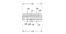
テープファスナ10は、互いに並行して横方向へ延びる外側テープ片15及び内側テープ片16と、内側テープ片16上で横方向へ延びるフック部材17とから形成されている。外側テープ片15には、プラスチックフィルムや繊維不織布が使用されている。内側テープ片16には、繊維不織布が使用されている。フック部材17は、フックバッキング18から突出する複数のフック19を有し、プラスチック繊維シートから形成されている。
The
外側テープ片15は、サイドフラップ8の外面に固定された基端部20と、基端部20に連なってサイドフラップ8の側縁8aから横方向外方へ延出する遠位部21とを有する。内側テープ片16は、サイドフラップ8の内面に固定された基端部22と、基端部22に連なってサイドフラップ8の側縁8aから横方向外方へ延出する第1遠位部23と、第1遠位部23に連なって外側テープ片15の遠位部21から横方向外方へ延出する第2遠位部24とを有する。外側テープ片15の基端部20がサイドフラップ8の外面に、内側テープ片16の基端部22がサイドフラップ8の内面にそれぞれ固定され、かつ、外側テープ片15の遠位部21と内側テープ片16の第1遠位部23とが接合することで、外側及び内側テープ片15,16は、基端部20,22がサイドフラップ8を挟んだ状態で、Y形に互いに接合されている。なお、図示とは異なり、外側テープ片15の基端部20がサイドフラップ8の内面に、かつ、内側テープ片16の基端部22がサイドフラップ8の外面に、それぞれ固定されてもよい。
The
外側テープ片15と内側テープ片16とは、基端部20,22と遠位部21,23,24とにおける縦方向の寸法L4,L5(幅寸法)がほぼ同一である。外側テープ片15と内側テープ片16とでは、遠位部21の内面と第1遠位部23の外面とが接着剤25を介して断続的に固定されている。
The
フック部材17は、内側テープ片16の第1遠位部23のほぼ全域と、内側テープ片16の第2遠位部24のうちの先端部24aを除いた部分とに配置されている。フック部材17は、フックバッキング18の内面が接着剤26を介して第1および第2遠位部23,24の外面に固定されている。第2遠位部24の先端部24aには、テープファスナ10の摘みタブ27が形成されている。
The
テープファスナ10は、外側テープ片15の遠位部21及び内側テープ片16の第1遠位部23が延びる第1区域28と、内側テープ片16の第2遠位部24が延びる第2区域29とを有する。テープファスナ10では、第1区域28が外側及び内側テープ片15,16とフック部材17とから形成され、第2区域29が内側テープ片16とフック部材17とから形成されており、したがって、第2区域29の剛性は第1区域28の剛性よりも低い。
The
ターゲット域11は、その平面形状が横方向へ長い矩形を呈し、ループバッキング30aから突出する複数のループ30bを有するループ部材31の内面を接着剤(図示せず)を介して裏面シート3の外面に接合することで形成されている。ただし、裏面シート3が、フックが解除可能に係合するループ機能を有する繊維不織布などの材料からなる場合には、ループ部材31を使用する必要がない。なお、図1では、ループ30bの図示を一部省略しているが、ループ30bはループバッキング30aの全域に形成されている。
The target area 11 has a rectangular shape whose planar shape is long in the lateral direction, and the inner surface of the
バリヤシート12は、サイドフラップ8に固定されて縦方向へ延びる基側部32と、基側部32に連なって縦方向へ延びる遠位側部33と、エンドフラップ9に位置しておむつ1Aの横方向内方へ倒伏してそこに固定された両端部34とを有する。遠位側部33の側縁には、縦方向へ延びる伸縮性弾性部材35が収縮可能に取り付けられている。弾性部材35は、遠位側部33の一部に覆われた状態で、そこに固定されている。したがって、おむつ1Aが表面シート2を内側にして縦方向へ湾曲すると、弾性部材35が収縮して遠位側部33が表面シート2の上方へ起立し、遠位側部33が排泄物に対する障壁を形成する。
The
サイドフラップ8は、コア4の側縁4aから横方向外方へ延びた裏面シート3の側部3aのみから形成されている。サイドフラップ8には、コア4の側縁4aから横方向外方へわずかに延びた表面シート2の側部2aとバリヤシート12の基側部32とが接合されている。レッグ用弾性部材13は、裏面シート3の側部3aとバリヤシート12の基側部32との間に介在し、それらシート3,12の間に固定されている。
The
サイドフラップ8では、外側テープ片15の基端部20の内面が接着剤36を介して裏面シート3の外面に断続的に固定され、内側テープ片16の基端部22の外面が接着剤37を介してバリヤシート12の内面に断続的に固定されている。
In the
エンドフラップ9は、コア4の端縁4bから縦方向外方へ延びる表面シート2の端部2bと裏面シート3の端部3bとから形成されている。エンドフラップ9では、表裏面シート2,3の端部2b,3bが互いに重なり合った状態で、それらシート2,3が接合されている。ウエスト用弾性部材14は、表面シート2の端部2bと裏面シート3の端部3bとの間に介在し、それらシート2,3の間に固定されている。バリヤシート12の両端部34は、表面シート2の外面に固定されている。
The
おむつ1Aを着用するには、後側ウエスト域7のサイドフラップ8を前側ウエスト域5のサイドフラップ8の外側に重ね合わせ、テープファスナ10をターゲット域11に止着して前側ウエスト域5と後側ウエスト域7とを連結する。テープファスナ10をターゲット域11に止着するには、テープファスナ10の摘みタブ27を摘持して第1および第2区域28,29をターゲット域11に押し付け、フック19とループ30bとを係合させる。前後側ウエスト域5,7が連結されたおむつ1Aには、ウエスト開口と一対のレッグ開口とが形成される(図示せず)。おむつ1Aの着用中に排泄された排泄物は、表面シート2を透過してコア4に吸収、保持される。
In order to wear the
おむつ1Aは、テープファスナ10が外側テープ片15と内側テープ片16とから形成され、それらテープ片15,16が、基端部20,22でサイドフラップ8を挟み、かつ、Y形に連結して固定されているので、テープファスナ10が1枚のテープ片から形成されている場合と比較し、サイドフラップ8に対するファスナ手段10の剥離強度を向上させることができる。
In the
おむつ1Aの着用中に着用者の動きによって、ターゲット域11が、撓んだり捩れたりして不規則に変形する。しかし、テープファスナ10の第2区域29の剛性が低いので、第2区域29がターゲット域11の撓みや捩れに追従することができ、ターゲット域11のループ30bの動きにあわせて内側テープ片16の第2遠位部24に位置するフック19が動くので、おむつ1Aの着用中にフック19がループ30bから不用意に外れることはない。着用者が激しく動いたとしても、前後ウエスト域5,7の連結を確実に維持することができる。
The target area 11 is irregularly deformed by bending or twisting due to the movement of the wearer during wearing of the
第2区域29がターゲット域11の撓みや捩れに追従して動いたとしても、テープファスナ10の第1区域28の剛性が第2区域29のそれよりも高く、第2区域29の動きが第1区域28で抑制される。第2区域29の動きが基端部20,22に伝わり難く、基端部20,22に作用する剥離力や剪断力を減少させることができるので、基端部20,22がサイドフラップ8から剥がれてしまうことはない。
Even if the
フック部材17が内側テープ片16の第2遠位部24のみならず、第1遠位部23にも配置されており、テープファスナ10をターゲット域11に止着すると、第2遠位部24に位置するフック19がループ30bと係合するとともに、第1遠位部23に位置するフック19がループ30bと係合する。剛性が高い第1区域28がフック19を介してターゲット域11に止着されるので、第1区域28の剛性によって区域28に重なるターゲット域11の部分の撓みや捩れが抑制され、ターゲット域11の撓みや捩れが内外側テープ片15,16の基端部20,22に伝わることを確実に防ぐことができる。
The
テープファスナ10は、第1区域28のガーレ剛軟度が5.0〜12mNの範囲にあり、第2区域29のガーレ剛軟度が0.3〜4.6mNの範囲にある。第1区域28のガーレ剛軟度が5.0mN未満では、第2区域29の動きを第1区域28で抑制することができず、第2区域29の動きが第1区域28を介して基端部20,22に容易に伝わり、基端部20,22に作用する剥離力や剪断力を減少させることができない。また、第1区域28によって区域28に重なるターゲット域11の部分の撓みや捩れを抑制することができない。第1区域28のガーレ剛軟度が12mNを超過すると、第1区域28が必要以上に硬化し、第1区域28が着用者の肌に接したときに不快な刺激を与える。第2区域29のガーレ剛軟度が0.3mN未満では、ターゲット域11の撓みや捩れによって第2区域29が破損してしまう場合がある。第2区域29のガーレ剛軟度が4.6mNを超過すると、第2区域29がターゲットテープ11の撓みや捩れに追従することができず、ループ30bの動きに第2区域29に位置するフック19がついていくことができないので、おむつ1Aの着用中にフック19がループ30bから不用意に外れてしまう場合がある。
The
テープファスナ10では、外側テープ片15のガーレ剛軟度が0.01〜0.35mNの範囲、内側テープ片16のガーレ剛軟度が0.3〜0.55mNの範囲にあり、フック部材17のガーレ剛軟度が0.28〜0.32mNの範囲にあることが好ましい。外側テープ片15のガーレ剛軟度が0.01mN未満、内側テープ片16のガーレ剛軟度が0.3mN未満、フック部材17のガーレ剛軟度が0.28mN未満では、第1区域28のガーレ剛軟度が5.0mN未満になり、第2区域29の動きが第1区域28を介して基端部20,22に容易に伝わってしまう。内側テープ片16のガーレ剛軟度が0.55mNを超過し、フック部材17のガーレ剛軟度が0.32mNを超過すると、第2区域29のガーレ剛軟度が4.6mNを超過し、第2区域29がターゲット域11の撓みや捩れに追従することができない。なお、テープファスナ10の第1および第2区域28,29のガーレ剛軟度の測定、内外側テープ片15,16やフック部材17のガーレ剛軟度の測定は、以下の方法で測定した。
(1)テープファスナ10の第1および第2区域28,29をおむつ1Aから切り取るとともに、第1区域28と第2区域29とを分断し、第1区域28の剛軟度測定用試料と第2区域29の剛軟度測定用試料とを作成する。また、外側テープ片15単体の剛軟度測定用試料や内側テープ片16単体の剛軟度測定用試料、フック部材17単体の剛軟度測定用試料を用意する。それら試料は、長さ寸法が約38mm、幅寸法が約25mmである。
(2)ガーレ剛軟度の測定は、ガーレ式剛軟度試験機を使用した。試験機における測定手順は、以下のとおりである。(a)試料の一端部が試験機の振り子にかかるように、試料の他端部を試験機のチャックに挟む。(b)試験機の目盛りが3〜6の間になるように補助重りを取り付ける。(c)スイッチを押し、試料から振り子の回転ロッドが離れる瞬間の目盛りを読む。目盛りの読みは、右と左との両者について行う。
(3)ガーレ剛軟度は、式;(右の場合の目盛りの数値+左の場合の目盛りの数値/2)×{(A×1+B×2+C×3)/5}×(試料の縦寸法(インチ)/試料の横寸法(インチ))×9.88、A,B,C;(重りを入れた場合の孔の位置:1インチ目−Ag、2インチ目−Bg、3インチ目−Cg)で算出した後、N(ニュートン)単位に換算した値である。
In the
(1) The first and
(2) The Gurley bending resistance was measured using a Gurley bending resistance tester. The measurement procedure in the testing machine is as follows. (A) The other end of the sample is sandwiched between chucks of the tester so that one end of the sample is applied to the pendulum of the tester. (B) Attach an auxiliary weight so that the scale of the testing machine is between 3 and 6. (C) Press the switch and read the scale at the moment when the rotating rod of the pendulum leaves the sample. The scale is read for both right and left.
(3) Gurley bending resistance is expressed by the equation: (scale value in the case of right + scale value in the case of left / 2) × {(A × 1 + B × 2 + C × 3) / 5} × (vertical dimension of sample (Inch) / horizontal dimension of sample (inch) × 9.88, A, B, C; (Position of hole when weight is added: 1 inch—Ag, 2 inches—Bg, 3 inches— After calculating by Cg), it is a value converted to N (Newton) unit.
テープファスナ10では、内側シート片16の第2遠位部24に位置するフック部材17の面積が1.75〜8.0cm2の範囲にある。面積が1.75cm2未満では、第2区域29においてループ30bに係合するフック19の数が低下し、ターゲット域11に対するテープファスナ10の第2区域29の係合が不十分となり、ターゲット域11の撓みや捩れによって、第2区域29に位置するフック19とループ30bとの係合が解除されてしまう場合がある。
In the
テープファスナ10では、外側テープ片15の遠位部21の横方向の寸法L1(長さ寸法)と内側テープ片16の第1遠位部23の横方向の寸法L2(長さ寸法)とが8〜15mmの範囲、内側テープ片16の第2遠位部24の横方向の寸法L3(長さ寸法)が17〜22mm(寸法L3のうち、摘みタブ27の寸法10mm)の範囲にあることが好ましく、外側テープ片15の遠位部21における縦方向の寸法L4(幅寸法)が25〜45mmの範囲、内側テープ片16の第1および第2遠位部23,24における縦方向の寸法L5(幅寸法)が25〜45mmの範囲にあることが好ましい。
In the
横方向の寸法L3が17mm未満かつ縦方向の寸法L5が25mm未満では、第2遠位部24におけるフック部材17の面積が1.75cm2未満となって、ターゲット域11に対するテープファスナ10の第2区域29の係合が不十分となり、ターゲット域11の撓みや捩れによって、第2区域29に位置するフック19とループ30bとの係合が解除されてしまう場合がある。横方向の寸法L1,L2が8mm未満かつ縦方向の寸法L4,L5が25mm未満では、第1区域28の面積が小さくなって第1区域28の剛性が低下し、第2区域29の動きを第1区域28で抑制することができず、第2区域29の動きが第1区域28を介して基端部20,22に容易に伝わってしまう。
When the lateral dimension L3 is less than 17 mm and the longitudinal dimension L5 is less than 25 mm, the area of the
図4は、他の一例として示すおむつ1Bの部分破断斜視図、図5は、図4のV−V線断面図、図6は、図4のVI−VI線断面図である。図4では、横方向を矢印L、縦方向を矢印Mで示し、厚み方向を矢印Nで示す。 4 is a partially broken perspective view of a diaper 1B shown as another example, FIG. 5 is a cross-sectional view taken along line VV in FIG. 4, and FIG. 6 is a cross-sectional view taken along line VI-VI in FIG. In FIG. 4, the horizontal direction is indicated by an arrow L, the vertical direction is indicated by an arrow M, and the thickness direction is indicated by an arrow N.
おむつ1Bは、その一部を除いて、おむつ1Aと同様な構成を有するので、おむつ1Aと同一の構成要素に同一の符号を付して、その構成の説明を省略する。
Since the diaper 1B has the same configuration as the
おむつ1Bでは、フック部材17がテープファスナ10の第2区域29のみに配置されている。おむつ1Bにおけるテープファスナ10では、第1区域28が外側テープ片15と内側テープ片16とから形成され、第2区域29が内側テープ片16とフック部材17とから形成されており、おむつ1Aにおけるテープファスナ10の場合と同様に、第2区域29の剛性が第1区域28の剛性よりも低くされている。テープファスナ10の第1および第2区域28,29のガーレ剛軟度の範囲、内外側テープ片15,16やフック部材17のガーレ剛軟度の範囲は、おむつ1Aのそれらと同一である。ただし、第2区域29は、外側テープ片15と内側テープ片16との二層から形成されている第1区域28と同様に、内側テープ片16とフック部材17との二層から形成されているのにもかかわらず、おむつ1Aにおけるテープファスナ10の場合と同様に、第2区域29の剛性が第1区域28の剛性よりも低くされているのは、外側テープ片15として、その前記ガーレ剛軟度の範囲内で、おむつ1Aのそれよりも剛性の高いものが使用されているからである。
In the diaper 1 </ b> B, the
第1および第2区域28,29や内外側テープ片15,16、フック部材17のガーレ剛軟度の測定方法は、おむつ1Aのそれと同一である。内側テープ片16の第2遠位部24に位置するフック部材17の面積は、おむつ1Aのそれと同一である。外側テープ片15の遠位部21と内側テープ片16の第1遠位部23との横方向の寸法L1,L2や内側テープ片16の第2遠位部24の横方向の寸法L3、内外側テープ片15,16の縦方向の寸法L4,L5は、おむつ1Aのそれらと同一である。
The measuring method of the Gurley bending resistance of the first and
表面シート2には、親水性繊維不織布、多数の開孔を有する疎水性繊維不織布、微細な多数の開孔を有するプラスチックフィルムのいずれかを使用することができる。裏面シート3やバリヤシート12には、疎水性繊維不織布、通気不透液性プラスチックフィルム、疎水性繊維不織布どうしをラミネートした複合不織布、疎水性繊維不織布と通気不透液性プラスチックフィルムとをラミネートした複合シートのいずれかを使用することができる。
As the
表裏面シート2,3やバリヤシート12、内外側テープ片15,16を形成する繊維不織布には、スパンレース、ニードルパンチ、メルトブローン、サーマルボンド、スパンボンド、ケミカルボンドの各製法により製造されたものを使用することができる。
The fiber nonwoven fabric forming the front and
裏面シート3やバリヤシート12、内外側テープ片15,16には、高い耐水性を有するメルトブローン法による繊維不織布の少なくとも片面に、高い強度と良好な柔軟性とを有するスパンボンド法による繊維不織布を重ね合わせた複合不織布(SM不織布またはSMS不織布)を使用することもできる。
The back sheet 3, the
親水性繊維不織布は、親水化処理が施された合成繊維、半合成繊維、再生繊維のうちのいずれか、または、それら繊維を混合した複合繊維から作ることができる。疎水性繊維不織布は、合成繊維から作ることができる。疎水性繊維不織布には、撥水処理が施された半合成繊維や再生繊維が含まれていてもよい。合成繊維には、特に限定はないが、ポリエステル系、ポリアクリロニトリル系、ポリ塩化ビニル系、ポリエチレン系、ポリプロピレン系、ポリスチレン系を使用することができる。合成繊維には、芯鞘型複合繊維、並列型複合繊維、異型中空繊維、微多孔繊維、接合型複合繊維を使用することもできる。 The hydrophilic fiber nonwoven fabric can be made from any one of synthetic fibers, semi-synthetic fibers and regenerated fibers that have been subjected to hydrophilic treatment, or composite fibers obtained by mixing these fibers. The hydrophobic fiber nonwoven fabric can be made from synthetic fibers. The hydrophobic fiber nonwoven fabric may contain semi-synthetic fibers and regenerated fibers that have been subjected to water repellent treatment. Although there is no limitation in particular in a synthetic fiber, a polyester type, a polyacrylonitrile type, a polyvinyl chloride type, a polyethylene type, a polypropylene type, and a polystyrene type can be used. As the synthetic fiber, a core-sheath type composite fiber, a parallel type composite fiber, an atypical hollow fiber, a microporous fiber, and a bonded type composite fiber can be used.
コア4は、フラッフパルプと高吸収性ポリマー粒子との混合物、または、フラッフパルプと高吸収性ポリマー粒子と熱可塑性合成樹脂繊維との混合物であり、所定の厚みに圧縮されている。コア4は、それの型崩れを防止するため、全体がティッシュペーパーや親水性繊維不織布等の透液性シートに包被されていることが好ましい。高吸収性ポリマーとしては、デンプン系、セルロース系、合成ポリマー系のものを使用することができる。高吸収性ポリマーには、繊維状のものを使用することができる。 The core 4 is a mixture of fluff pulp and superabsorbent polymer particles or a mixture of fluff pulp, superabsorbent polymer particles and thermoplastic synthetic resin fibers, and is compressed to a predetermined thickness. The core 4 is preferably encased in a liquid-permeable sheet such as tissue paper or hydrophilic fiber nonwoven fabric in order to prevent the core 4 from losing its shape. As the superabsorbent polymer, a starch-based, cellulose-based or synthetic polymer-based polymer can be used. A fibrous polymer can be used as the superabsorbent polymer.
表裏面シート2,3どうしの接合、表裏面シート2,3に対するバリヤシート12の接合、表裏面シート2,3に対するコア4の固定、表裏面シート2,3やバリヤシート12に対する弾性部材13,14,35の固定には、接着剤、または、ヒートシールやソニックシール等の熱による溶着手段を利用することができる。なお、サイドフラップ8に対する内外側テープ片15,16の基端部20,22の固着や内外側テープ片15,16の遠位部21,23どうしの固着、内側テープ片16に対するフック部材17の接合には、接着剤の他に、ヒートシールやソニックシール等の熱による溶着手段を利用することもできる。
Bonding between the front and
接着剤には、ホットメルト型接着剤やアクリル系接着剤、ゴム系接着剤を使用することができる。接着剤は、表裏面シート2,3やバリヤシート12、内外側テープ片15,16にスパイラル状、ジグザグ状、ドット状、縞状のうちのいずれかの態様で塗布されている。接着剤をそのような態様でそれらシート2,3,12やテープ片5,16に塗布すると、シート2,3,12やテープ片15,16に接着剤が塗布された塗布域と接着剤が塗布されていない非塗布域とが形成され、それらシート2,3,12どうしやテープ片15,16どうしが断続的に接合されるとともに、シート3,12とテープ片15,16とが断続的に接合される。
As the adhesive, a hot-melt adhesive, an acrylic adhesive, or a rubber adhesive can be used. The adhesive is applied to the front and
図示はしていないが、内側テープ片16が繊維不織布から形成されている場合、テープファスナ10の第1および第2区域28,29をおむつの横方向内方へ折曲し、それら区域28,29に位置するフック19を内側テープ片16の基端部22の外面に係合させることで、それら区域28,29を基端部22に仮止めすることができる。また、ターゲット域11には、倦縮繊維から形成された繊維不織布を使用することもできる。この場合は、フック19が倦縮繊維に引っ掛かるので、テープファスナ10をターゲット域11に止着することができる。
Although not shown, when the
1A 着用物品(使い捨ておむつ)
1B 着用物品(使い捨ておむつ)
2 第2面(透液性表面シート)
3 第1面(不透液性裏面シート)
4 吸液性コア
5 第2ウエスト域(前側ウエスト域)
6 股下域
7 第1ウエスト域(後側ウエスト域)
8 両側部(サイドフラップ)
8a 側縁
9 エンドフラップ
10 テープファスナ
11 ターゲット域
15 第1(外側)テープ片
16 第2(内側)テープ片
17 フック部材
19 フック
20 基端部
21 遠位部
22 基端部
23 第1遠位部
24 第2遠位部
24a 先端部
27 摘みタブ
28 第1区域
29 第2区域
30a ループバッキング
30b ループ
31 ループ部材
1A Wearing articles (disposable diapers)
1B Wearing articles (disposable diapers)
2 Second surface (liquid-permeable surface sheet)
3 1st surface (impermeable liquid back sheet)
4 Liquid-absorbing core 5 Second waist area (front waist area)
6 Inseam area 7 1st waist area (rear waist area)
8 Both sides (side flap)
Claims (6)
前記サイドフラップが前記裏面シートのみから形成されており、
前記バリヤシートが、前記サイドフラップに固定されて前記縦方向へ延びる基側部と、前記基側部に連なる遠位側部とを有し、前記遠位側部の側縁には伸縮性弾性部材が取り付けられており、
前記第1テープ片が、前記第1ウエスト域における前記サイドフラップの前記第1面に接合された基端部と、前記基端部に連なって横方向外方へ延出する遠位部とを有し、
前記第2テープ片が、前記第1ウエスト域における前記サイドフラップの前記第2面に接合された基端部と、前記基端部に連なって横方向外方へ延出して前記第1テープ片の前記遠位部に接合された第1遠位部と、前記第1遠位部に連なって前記第1テープ片の前記遠位部から横方向外方へ延出する第2遠位部とを有し、
前記フック部材が、前記第2テープ片の前記第1および第2遠位部のうちの少なくとも該第2遠位部に接合され、前記第2テープ片の前記第2遠位部が延びる前記テープファスナの第2区域の剛性が、前記第2テープ片の前記第1遠位部が延びる前記テープファスナの第1区域の剛性よりも低く、
前記横方向における前記第2テープ片の基端部の長さ寸法が、前記横方向における前記第1テープ片の基端部の長さ寸法よりも大きいものであって、
前記バリヤシートの基端部が、前記第2テープの前記基端部と前記サイドフラップとの間において固定されていることを特徴とする前記着用物品。 A longitudinal direction and a transverse direction, a first surface and a second surface opposite thereto, a liquid-permeable surface sheet, a liquid-impermeable back sheet, and a liquid-absorbent core interposed between the front and back sheets; A first waist region, a second waist region, a crotch region positioned between the first and second waist regions, and a pair extending in the longitudinal direction outward in the lateral direction from both side edges of the liquid-absorbent core First side flaps, a barrier sheet that is fixed to the pair of side flaps and extends in the longitudinal direction, and a first flap that is disposed to overlap each other in the side flaps of the first waist region and extends outward in the lateral direction. A tape fastener having a hook member formed from a tape piece and a second tape piece and a loop disposed on the first surface of the second waist region and releasably engaged with a plurality of hooks of the hook member. In the disposable wearing article comprising a fastener means consisting of a target area,
The side flap is formed only from the back sheet,
The barrier sheet has a base side portion fixed to the side flap and extending in the longitudinal direction, and a distal side portion connected to the base side portion, and a stretchable elasticity is provided on a side edge of the distal side portion. The member is attached,
The first tape piece includes a proximal end portion joined to the first surface of the side flap in the first waist region, and a distal portion extending laterally outwardly connected to the proximal end portion. Have
The second tape piece is joined to the second surface of the side flap in the first waist region, and extends outward in the lateral direction from the base end portion to the first tape piece. A first distal portion joined to the distal portion of the first distal portion, and a second distal portion extending laterally outward from the distal portion of the first tape piece connected to the first distal portion. Have
The tape, wherein the hook member is joined to at least the second distal portion of the first and second distal portions of the second tape piece, and the second distal portion of the second tape piece extends. The rigidity of the second area of the fastener is lower than the rigidity of the first area of the tape fastener from which the first distal portion of the second tape piece extends;
The length dimension of the proximal end portion of the second tape piece in the lateral direction is larger than the length dimension of the proximal end portion of the first tape piece in the lateral direction,
The wearing article, wherein a base end portion of the barrier sheet is fixed between the base end portion of the second tape and the side flap.
Priority Applications (6)
| Application Number | Priority Date | Filing Date | Title |
|---|---|---|---|
| JP2004139126A JP4359534B2 (en) | 2003-05-27 | 2004-05-07 | Disposable wearing items |
| MYPI20041988A MY134991A (en) | 2003-05-27 | 2004-05-25 | Disposable wearing article |
| US10/853,238 US7578813B2 (en) | 2003-05-27 | 2004-05-26 | Disposable wearing article |
| TW093115001A TWI252082B (en) | 2003-05-27 | 2004-05-26 | Disposable wearing article |
| CNB200410047583XA CN1329013C (en) | 2003-05-27 | 2004-05-27 | Disposable wearing article |
| KR1020040037648A KR101108303B1 (en) | 2003-05-27 | 2004-05-27 | Disposable wearing article |
Applications Claiming Priority (2)
| Application Number | Priority Date | Filing Date | Title |
|---|---|---|---|
| JP2003149372 | 2003-05-27 | ||
| JP2004139126A JP4359534B2 (en) | 2003-05-27 | 2004-05-07 | Disposable wearing items |
Publications (3)
| Publication Number | Publication Date |
|---|---|
| JP2005007159A JP2005007159A (en) | 2005-01-13 |
| JP2005007159A5 JP2005007159A5 (en) | 2007-06-21 |
| JP4359534B2 true JP4359534B2 (en) | 2009-11-04 |
Family
ID=33455551
Family Applications (1)
| Application Number | Title | Priority Date | Filing Date |
|---|---|---|---|
| JP2004139126A Expired - Fee Related JP4359534B2 (en) | 2003-05-27 | 2004-05-07 | Disposable wearing items |
Country Status (6)
| Country | Link |
|---|---|
| US (1) | US7578813B2 (en) |
| JP (1) | JP4359534B2 (en) |
| KR (1) | KR101108303B1 (en) |
| CN (1) | CN1329013C (en) |
| MY (1) | MY134991A (en) |
| TW (1) | TWI252082B (en) |
Families Citing this family (27)
| Publication number | Priority date | Publication date | Assignee | Title |
|---|---|---|---|---|
| MY139135A (en) * | 2004-06-30 | 2009-08-28 | Uni Charm Corp | Disposable wearing article |
| EP1669001A1 (en) * | 2004-12-10 | 2006-06-14 | 3M Innovative Properties Company | Strip of male fastening means, patch cut therefrom, and fastening tape tab comprising such patch |
| US20070142798A1 (en) * | 2005-12-16 | 2007-06-21 | The Procter & Gamble Company | Disposable absorbent article having serviceable indicia indicating improper fit |
| JP5175677B2 (en) * | 2008-10-02 | 2013-04-03 | 王子ネピア株式会社 | Fastening tape and disposable disposable diapers |
| US9138957B2 (en) | 2010-06-21 | 2015-09-22 | 3M Innovative Properties Company | Slit hook strips and laminates and articles containing the same |
| ES2929933T3 (en) | 2011-03-22 | 2022-12-05 | Avery Dennison Corp | Closure tape with patterned adhesive |
| JP5882648B2 (en) * | 2011-09-27 | 2016-03-09 | 大王製紙株式会社 | Tape type disposable diaper |
| JP6028989B2 (en) * | 2011-09-27 | 2016-11-24 | 大王製紙株式会社 | Tape type disposable diaper |
| JP5291215B1 (en) | 2012-03-30 | 2013-09-18 | ユニ・チャーム株式会社 | Disposable diapers |
| JP5505469B2 (en) * | 2012-07-11 | 2014-05-28 | 王子ホールディングス株式会社 | Fastening tape and disposable disposable diapers |
| JP5291231B1 (en) | 2012-09-28 | 2013-09-18 | ユニ・チャーム株式会社 | Disposable diapers |
| US10085897B2 (en) | 2013-02-15 | 2018-10-02 | The Procter & Gamble Company | Fastening systems for use with absorbent articles |
| JP6240411B2 (en) * | 2013-06-06 | 2017-11-29 | ユニ・チャーム株式会社 | Disposable diapers |
| US9615980B2 (en) | 2013-07-29 | 2017-04-11 | Kimberly-Clark Worldwide, Inc. | Absorbent article having a fastening system |
| US9265674B2 (en) * | 2013-07-29 | 2016-02-23 | Kimberly-Clark Worldwide, Inc. | Absorbent article having a fastening system with low stiffness |
| US9480611B2 (en) | 2013-07-29 | 2016-11-01 | Kimberly-Clark Worldwide, Inc. | Absorbent article having a fastening system |
| US20150032078A1 (en) | 2013-07-29 | 2015-01-29 | Kimberly-Clark Worldwide, Inc. | Absorbent article having a fastening system with a visual cue |
| US9339425B2 (en) | 2013-11-04 | 2016-05-17 | Kimberly-Clark Worldwide, Inc. | Absorbent article having a fastening system adapted to enhance gasketing |
| US9468569B2 (en) | 2013-11-04 | 2016-10-18 | Kimberly-Clark Worldwide, Inc. | Absorbent article having a fastening system and waist elastic with low load loss properties |
| MX350617B (en) * | 2013-11-27 | 2017-09-08 | Kimberly Clark Co | Absorbent article having a fastening system with a visual cue. |
| US9597237B2 (en) * | 2013-12-31 | 2017-03-21 | Kimberly-Clark Worldwide, Inc | Absorbent article having a fastening system |
| US9980859B2 (en) | 2014-01-31 | 2018-05-29 | Kimberly-Clark Worldwide, Inc. | Absorbent article having a fastening system with improved flexibility |
| JP6425403B2 (en) | 2014-04-14 | 2018-11-21 | スリーエム イノベイティブ プロパティズ カンパニー | Fixing member and absorbent article |
| JP2015205032A (en) * | 2014-04-21 | 2015-11-19 | スリーエム イノベイティブ プロパティズ カンパニー | fastening system |
| US9849043B2 (en) | 2014-10-31 | 2017-12-26 | Kimberly-Clark Worldwide, Inc. | Absorbent article having a protected fastening system |
| BR112017010279A2 (en) * | 2014-11-17 | 2018-01-02 | 3M Innovative Properties Co | absorbent article and fixing laminate |
| JP7049185B2 (en) * | 2018-05-28 | 2022-04-06 | 大王製紙株式会社 | Tape type disposable diapers |
Family Cites Families (21)
| Publication number | Priority date | Publication date | Assignee | Title |
|---|---|---|---|---|
| US3848594A (en) | 1973-06-27 | 1974-11-19 | Procter & Gamble | Tape fastening system for disposable diaper |
| US3999545A (en) * | 1975-12-19 | 1976-12-28 | Johnson & Johnson | Diaper having tab fastener with zone coated adhesive |
| US4846815A (en) * | 1987-01-26 | 1989-07-11 | The Procter & Gamble Company | Disposable diaper having an improved fastening device |
| US5019065A (en) * | 1987-12-17 | 1991-05-28 | The Procter & Gamble Company | Disposable absorbent article with combination mechanical and adhesive tape fastener system |
| US5279604A (en) * | 1987-12-17 | 1994-01-18 | The Procter & Gamble Company | Mechanical fastening systems with disposal means for disposable absorbent articles |
| US5176671A (en) * | 1988-12-20 | 1993-01-05 | Kimberly-Clark Corporation | Fastening system for disposable diaper with disposability feature |
| EP0563458A1 (en) * | 1992-04-02 | 1993-10-06 | The Procter & Gamble Company | Adhesive/mechanical fastener systems for disposable absorbent articles with grip tab |
| US6994698B2 (en) * | 1994-12-28 | 2006-02-07 | Kimberly-Clark Worldwide, Inc. | Flexible mechanical fastening tab |
| US5554146A (en) * | 1994-05-06 | 1996-09-10 | Minnesota Mining And Manufacturing Company | Mechanical fastener for disposable article |
| US5611789A (en) * | 1995-03-08 | 1997-03-18 | Minnesota Mining And Manufacturing Company | Disposable diaper mechanical closure system with adhesive disposability |
| US6007527A (en) * | 1995-12-04 | 1999-12-28 | Kao Corporation | Disposable diaper with a mechanical fastener and an adhesive tab for disposing of the diaper |
| JP3215314B2 (en) | 1996-01-23 | 2001-10-02 | ユニ・チャーム株式会社 | Fastening structure for worn articles |
| WO1997028774A1 (en) * | 1996-02-09 | 1997-08-14 | Avery Dennison Corporation | Diapers having precombined mechanical closures |
| JPH10137008A (en) * | 1996-11-15 | 1998-05-26 | Kao Corp | Tape having mechanical hook |
| US6068620A (en) * | 1998-03-30 | 2000-05-30 | Paragon Trade Brands | Absorbent laminate |
| JP2000197660A (en) | 1999-01-05 | 2000-07-18 | Elleair Paper Tekku Kk | Disposable diaper |
| JP3626647B2 (en) * | 1999-11-30 | 2005-03-09 | ユニ・チャーム株式会社 | Disposable diapers |
| US6363587B1 (en) | 2000-02-07 | 2002-04-02 | 3M Innovative Properties Company | Perforated release tape |
| JP4615140B2 (en) * | 2001-03-03 | 2011-01-19 | 大王製紙株式会社 | A disposable diaper with a fixed front seat |
| US6740071B2 (en) * | 2001-12-12 | 2004-05-25 | Paragon Trade Brands, Inc. | Absorbent garment tab having zones of different elasticity |
| US6692477B2 (en) * | 2001-12-12 | 2004-02-17 | Paragon Trade Brands, Inc. | Absorbent garment tab having zones of different elasticity |
-
2004
- 2004-05-07 JP JP2004139126A patent/JP4359534B2/en not_active Expired - Fee Related
- 2004-05-25 MY MYPI20041988A patent/MY134991A/en unknown
- 2004-05-26 US US10/853,238 patent/US7578813B2/en not_active Expired - Fee Related
- 2004-05-26 TW TW093115001A patent/TWI252082B/en not_active IP Right Cessation
- 2004-05-27 KR KR1020040037648A patent/KR101108303B1/en active IP Right Grant
- 2004-05-27 CN CNB200410047583XA patent/CN1329013C/en not_active Expired - Fee Related
Also Published As
| Publication number | Publication date |
|---|---|
| MY134991A (en) | 2008-01-31 |
| CN1572266A (en) | 2005-02-02 |
| KR101108303B1 (en) | 2012-01-25 |
| TWI252082B (en) | 2006-04-01 |
| CN1329013C (en) | 2007-08-01 |
| KR20040101945A (en) | 2004-12-03 |
| TW200505364A (en) | 2005-02-16 |
| JP2005007159A (en) | 2005-01-13 |
| US20040243091A1 (en) | 2004-12-02 |
| US7578813B2 (en) | 2009-08-25 |
Similar Documents
| Publication | Publication Date | Title |
|---|---|---|
| JP4359534B2 (en) | Disposable wearing items | |
| EP1247507B1 (en) | Disposable wearing article | |
| EP0818188B1 (en) | Disposable diaper | |
| JP4875350B2 (en) | Disposable diapers | |
| KR100784778B1 (en) | Wearing article | |
| KR100673919B1 (en) | Disposable diaper | |
| AU2010225865B2 (en) | Disposable diaper having a fastening tape with stepwise adjustable length | |
| JP2005052209A (en) | Disposable diaper | |
| JP4050920B2 (en) | Disposable diapers | |
| EP1287800A2 (en) | Open-type disposable diaper | |
| JP6192447B2 (en) | Absorbent articles | |
| CN115038419B (en) | Connected disposable wearing article | |
| JP4190276B2 (en) | Disposable diapers | |
| JP4171671B2 (en) | Open-type disposable diapers | |
| JP4813156B2 (en) | Disposable diapers | |
| JP5497375B2 (en) | Disposable diapers | |
| JP2003153954A (en) | Open type disposal diaper | |
| JP2020141869A5 (en) | ||
| JP7212985B2 (en) | Articulated disposable wearing article | |
| JP7290959B2 (en) | Articulated disposable wearing article | |
| JP5955726B2 (en) | Disposable diapers | |
| JP2020141868A5 (en) | ||
| JP2003144490A (en) | Throwaway diaper | |
| JP4304149B2 (en) | Disposable diapers | |
| JP2020103356A5 (en) |
Legal Events
| Date | Code | Title | Description |
|---|---|---|---|
| RD04 | Notification of resignation of power of attorney |
Free format text: JAPANESE INTERMEDIATE CODE: A7424 Effective date: 20050426 |
|
| A521 | Written amendment |
Free format text: JAPANESE INTERMEDIATE CODE: A523 Effective date: 20070507 |
|
| A621 | Written request for application examination |
Free format text: JAPANESE INTERMEDIATE CODE: A621 Effective date: 20070507 |
|
| A977 | Report on retrieval |
Free format text: JAPANESE INTERMEDIATE CODE: A971007 Effective date: 20080908 |
|
| A131 | Notification of reasons for refusal |
Free format text: JAPANESE INTERMEDIATE CODE: A131 Effective date: 20080916 |
|
| A521 | Written amendment |
Free format text: JAPANESE INTERMEDIATE CODE: A523 Effective date: 20081114 |
|
| A131 | Notification of reasons for refusal |
Free format text: JAPANESE INTERMEDIATE CODE: A131 Effective date: 20090512 |
|
| A521 | Written amendment |
Free format text: JAPANESE INTERMEDIATE CODE: A523 Effective date: 20090709 |
|
| TRDD | Decision of grant or rejection written | ||
| A01 | Written decision to grant a patent or to grant a registration (utility model) |
Free format text: JAPANESE INTERMEDIATE CODE: A01 Effective date: 20090804 |
|
| A01 | Written decision to grant a patent or to grant a registration (utility model) |
Free format text: JAPANESE INTERMEDIATE CODE: A01 |
|
| A61 | First payment of annual fees (during grant procedure) |
Free format text: JAPANESE INTERMEDIATE CODE: A61 Effective date: 20090810 |
|
| FPAY | Renewal fee payment (event date is renewal date of database) |
Free format text: PAYMENT UNTIL: 20120814 Year of fee payment: 3 |
|
| R150 | Certificate of patent or registration of utility model |
Ref document number: 4359534 Country of ref document: JP Free format text: JAPANESE INTERMEDIATE CODE: R150 Free format text: JAPANESE INTERMEDIATE CODE: R150 |
|
| FPAY | Renewal fee payment (event date is renewal date of database) |
Free format text: PAYMENT UNTIL: 20120814 Year of fee payment: 3 |
|
| FPAY | Renewal fee payment (event date is renewal date of database) |
Free format text: PAYMENT UNTIL: 20130814 Year of fee payment: 4 |
|
| R250 | Receipt of annual fees |
Free format text: JAPANESE INTERMEDIATE CODE: R250 |
|
| R250 | Receipt of annual fees |
Free format text: JAPANESE INTERMEDIATE CODE: R250 |
|
| R250 | Receipt of annual fees |
Free format text: JAPANESE INTERMEDIATE CODE: R250 |
|
| R250 | Receipt of annual fees |
Free format text: JAPANESE INTERMEDIATE CODE: R250 |
|
| R250 | Receipt of annual fees |
Free format text: JAPANESE INTERMEDIATE CODE: R250 |
|
| R250 | Receipt of annual fees |
Free format text: JAPANESE INTERMEDIATE CODE: R250 |
|
| R250 | Receipt of annual fees |
Free format text: JAPANESE INTERMEDIATE CODE: R250 |
|
| LAPS | Cancellation because of no payment of annual fees |