JP2015200716A - Lens system and imaging apparatus including the same - Google Patents
Lens system and imaging apparatus including the same Download PDFInfo
- Publication number
- JP2015200716A JP2015200716A JP2014078071A JP2014078071A JP2015200716A JP 2015200716 A JP2015200716 A JP 2015200716A JP 2014078071 A JP2014078071 A JP 2014078071A JP 2014078071 A JP2014078071 A JP 2014078071A JP 2015200716 A JP2015200716 A JP 2015200716A
- Authority
- JP
- Japan
- Prior art keywords
- lens
- unit
- warning
- optical element
- movable optical
- Prior art date
- Legal status (The legal status is an assumption and is not a legal conclusion. Google has not performed a legal analysis and makes no representation as to the accuracy of the status listed.)
- Granted
Links
Images


Abstract
Description
本発明は、レンズシステムに関し、特に、ズームレンズ、フォーカスレンズ、アイリス等の可動光学部材、及び、それらの位置を検出する位置検出装置を有するレンズシステム及びそれを有する撮像装置に関する。 The present invention relates to a lens system, and more particularly, to a movable optical member such as a zoom lens, a focus lens, and an iris, and a lens system having a position detection device that detects the positions thereof, and an imaging apparatus having the lens system.
現在、テレビや映画の撮影に使用するレンズシステムには、ズームやフォーカスといった可動光学部材をよりなめらかに操作するために、電動操作可能とすることが必須となってきている。一方で、従来の操作リングを直接手で回転させるといった手動操作に慣れたユーザからは、電動操作だけでなく従来の手動操作もできるようにしてほしい、という要望もある。 At present, in a lens system used for shooting a television or a movie, it is indispensable to be able to perform an electric operation in order to operate a movable optical member such as zoom and focus more smoothly. On the other hand, there is a demand from users who are accustomed to manual operation such as directly rotating a conventional operation ring by hand to enable not only electric operation but also conventional manual operation.
特許文献1では、このような要望に答えるため、従来の手動操作可能なレンズユニットに、電動操作可能で着脱可能なアクセサリユニットを備えるレンズシステムが提案されている。
In order to respond to such a request,
可動光学部材を持つレンズユニットから、可動光学部材の位置を検出する検出器を持つアクセサリユニットを1度外してから再び装着した時には、各光学部材位置算出のための調整を行う必要がある。また、アクセサリユニットは固有のレンズユニットのトルクや光学部材端位置のバラつきを補正するため、工場出荷時に、レンズユニットとアクセサリユニットが対で調整されているのが一般的である。また、レンズユニット及びアクセサリユニットには同一の製造番号また対で調整されたことがわかるような同一のユニークな番号が記入されている。 When an accessory unit having a detector for detecting the position of the movable optical member is removed from the lens unit having the movable optical member and then attached again, it is necessary to make adjustments for calculating the position of each optical member. In addition, since the accessory unit corrects the inherent lens unit torque and variations in the optical member end position, the lens unit and the accessory unit are generally adjusted in pairs at the time of shipment from the factory. In addition, the lens unit and the accessory unit are filled with the same manufacturing number or the same unique number so that it can be seen that they are adjusted in pairs.
また、映画撮影では、通常、映像の記録と共に映像に関する情報も記録している。例えば撮影レンズの被写体距離、焦点距離、絞り情報等がメタデータ記録されている。 In movie shooting, information related to video is usually recorded together with video recording. For example, the subject distance, focal length, aperture information, and the like of the photographing lens are recorded as metadata.
複数の同一仕様のレンズユニットを保有しているユーザにおいて、アクセサリユニットを着脱した際に、対で調整されたアクセサリユニットとレンズユニットの組み合わせを示す番号を見落として、調整時とは異なるペアで組み合わせてしまうことがある。その場合、位置検出器の出力値の範囲が異なったり、トルクのバラつきを補正できないなど所定の制御性能を得ることができかったりする。 For users who have multiple lens units of the same specification, when attaching or detaching the accessory unit, the number indicating the combination of the accessory unit and the lens unit adjusted in pairs is overlooked and combined in a pair different from the adjustment unit. May end up. In that case, predetermined control performance cannot be obtained, for example, the range of the output value of the position detector is different or the torque variation cannot be corrected.
そこで、本発明の目的は、可動光学部材を持つレンズユニットにアクセサリユニットを装着した時に、その組み合わせが所定の組み合わせと一致していない場合、ユーザに警告することを可能としたレンズ装置を提供することである。 Therefore, an object of the present invention is to provide a lens device that can warn a user when an accessory unit is attached to a lens unit having a movable optical member, and the combination does not match a predetermined combination. That is.
上記目的を達成するために、本発明のレンズシステムは、可動光学要素を有するレンズユニットと、前記レンズユニットに着脱可能で、前記可動光学要素を駆動するための駆動手段と該可動光学要素の位置に対応する信号を検出する位置検出手段を有するアクセサリユニットと、を有し、前記レンズユニットは該レンズユニットの識別情報であるレンズIDを前記アクセサリユニットに出力するID出力手段を有し、前記アクセサリユニットは、接続されるべきレンズユニットの識別情報である基準IDを記憶するID記憶手段と、警告を行う警告手段と、前記基準IDと前記レンズIDとを比較するID比較手段を有し、前記ID比較手段は、前記基準IDと前記レンズIDとを比較し一致しない場合は、前記警告手段により警告する、ことを特徴とする。 In order to achieve the above object, a lens system of the present invention includes a lens unit having a movable optical element, a drive unit that can be attached to and detached from the lens unit, and that drives the movable optical element, and a position of the movable optical element. An accessory unit having a position detection unit that detects a signal corresponding to the lens unit, and the lens unit has an ID output unit that outputs a lens ID that is identification information of the lens unit to the accessory unit, and the accessory The unit includes an ID storage unit that stores a reference ID that is identification information of a lens unit to be connected, a warning unit that performs a warning, and an ID comparison unit that compares the reference ID and the lens ID. The ID comparison means compares the reference ID with the lens ID and warns by the warning means if they do not match. The features.
本発明によれば、可動光学部材を持つレンズユニットに可動光学部材の位置を検出するアクセサリユニットを装着した時に、レンズユニットとアクセサリユニットの組み合わせが所定の組み合わせと一致していない場合に、ユーザに警告することを可能としたレンズ装置及びそれを有する撮像装置を提供できる。 According to the present invention, when the accessory unit for detecting the position of the movable optical member is attached to the lens unit having the movable optical member, when the combination of the lens unit and the accessory unit does not match the predetermined combination, It is possible to provide a lens apparatus capable of warning and an imaging apparatus having the lens apparatus.
以下に、本発明の好ましい実施の形態を、添付の図面に基づいて詳細に説明する。 Hereinafter, preferred embodiments of the present invention will be described in detail with reference to the accompanying drawings.
図1は、本発明を適用できる実施例1のレンズ装置の構成を示したものである。
本実施例のレンズ装置は、大きく分けてレンズユニット1、アクセサリユニット2の2つで構成される。ただし、レンズユニット1とアクセサリユニット2は着脱可能な構造となっており、マニュアル操作のみで撮影するなどの場合には、レンズユニット1のみの構成として使用される。
FIG. 1 shows a configuration of a lens apparatus according to a first embodiment to which the present invention can be applied.
The lens apparatus of the present embodiment is roughly composed of two units, a
レンズユニット1の詳細構成について説明する。
絞り101はレンズユニット1が結像する像の光量、及び、焦点深度を変化させるための光学素子であり、絞り操作リング102を回転することで機構的に開口絞り101の開口径を操作することができる。
A detailed configuration of the
The
フォーカスレンズ群103は光軸方向に移動することで、レンズユニット1の結像位置を変位させるための光学素子である。フォーカス操作リング104を回転することで、機構的にフォーカスレンズ群101を光軸方向に操作することができる。
The
レンズCPU111は、後述するソフトウェア処理によって、レンズユニット1とアクセサリユニット2との着脱検出、アクセサリCPU211と通信等を行うデバイスである。
The
レンズEEPROM112は不揮発性のメモリであって、レンズCPU111の指令に応じて、後述するレンズユニットの識別情報等を記憶する記憶デバイスである。
The lens EEPROM 112 is a non-volatile memory, and is a storage device that stores lens unit identification information, which will be described later, in accordance with a command from the
次に、アクセサリユニット2の詳細構成について説明する。
絞りモータ201は、レンズユニット1に装着時にレンズユニット1の絞り操作リング102と係合する絞りギア202を介して絞り操作リング102を回転させるアクチュエータである。絞り位置検出器203(位置検出手段)は絞りギア202の回転位置を検出する検出器である。
Next, a detailed configuration of the
The
フォーカスモータ204は、レンズユニット1に装着時にレンズユニット1のフォーカス操作リング104と係合するフォーカスギア205を介してフォーカス操作リング104を回転させるアクチュエータである。フォーカス位置検出器206(位置検出手段)はフォーカスギア205の回転位置を検出する検出器である。
The
アクセサリCPU211(ID比較手段)は、後述するソフトウェア処理によって、絞りモータ201とフォーカスモータ204の制御、レンズCPU111と通信等を行うデバイスである。
The accessory CPU 211 (ID comparison unit) is a device that controls the
アクセサリEEPROM212は不揮発性のメモリであって、アクセサリCPU211の指令に応じて、後述するアクセサリユニットの識別情報等を記憶する記憶デバイスである。
The accessory EEPROM 212 is a nonvolatile memory, and is a storage device that stores accessory unit identification information, which will be described later, in accordance with a command from the
表示器213はアクセサリCPU211の指令に応じて、レンズユニット1やアクセサリユニット2の各種内部情報を表示するデバイスである。また、図示はしてないがアクセサリCPU211よりカメラに対して被写体距離、焦点距離、絞り情報といったレンズ情報を出力する機能も有している。
The
次に、アクセサリCPU211(ID比較手段)で行うソフトウェア処理について説明する。図2は実施例1におけるアクセサリCPU211で行う全体処理のフローチャートである。
Next, software processing performed by the accessory CPU 211 (ID comparison unit) will be described. FIG. 2 is a flowchart of overall processing performed by the
はじめに、レンズユニット1に電源を供給し、レンズCPU111とアクセサリCPU211とを通信可能にする。このとき、S101でレンズEEPROM112に記憶されている識別情報をレンズCPU111(ID出力手段)が読み込み、アクセサリCU211に送信する。アクセサリCPU211ではレンズCPU111より送信された識別情報を受信する。レンズEEPROM112には予めレンズユニット固有に付与されたユニークな番号(識別情報)が記憶されており、製造番号や任意の文字列が用いられる。また、レンズEEPROM112には固有のレンズユニットに応じたレンズ光学部材端位置やレンズ制御補正データ等も記憶されている。
First, power is supplied to the
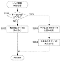
続いて、S102ではアクセサリEEPROM212に記憶されているレンズユニット1の識別情報を読み出す。S103では、アクセサリEEPROM212に対応するレンズユニットの識別情報が設定されていない場合は、レンズユニット1から受信した識別情報を対応するレンズユニットの識別情報としてレンズEEPROM112に書き込み(S104)、処理を完了する。EEPROM212に既に対応するレンズユニットの識別情報(基準ID)が設定されている場合は、レンズユニット1より受信した識別情報(レンズID)とEEPROM212に記憶されているレンズユニットの識別情報(基準ID)とを比較(S105)する。一致した場合は処理を完了する。一致しない場合は表示器213に図3の様な警告出力を行う。
Subsequently, in S102, the identification information of the
本実施例の効果について説明する。
従来では、アクセサリユニット2をレンズユニット1から外し、ユーザが組み合わせ番号を確認せず再び装着した場合で、調整されたアクセサリユニットとレンズユニットとは異なる組み合わせで装着されてしまう場合がある。その時には、ユーザは、実際に動作させ、所定の端位置まで動作しなかったり、所定の制御性能が出なかったりするなどの現象が発生するまで誤った組み合わせで装着されていることに気付きにくい。
The effect of the present embodiment will be described.
Conventionally, when the
その結果、気付くまでに間違った位置データをメタデータとして映像信号に記憶してしまうといった問題が生じていた。 As a result, there has been a problem that wrong position data is stored in the video signal as metadata before it is noticed.
しかし本実施例では、位置検出機能を持つアクセサリユニット2が光学素子を持つレンズユニット1の識別情報(レンズID)を読み出し、アクセサリユニット2がペアのユニットとして記憶しているレンズユニット1の識別情報(基準ID)とを比較する。そして、その識別情報が異なる時、ユーザに警告表示を行うことによりユーザは撮影を開始する前にレンズユニット1とアクセサリユニット2の正しい組み合せに戻すことが可能となる。
However, in this embodiment, the
なお、本実施例では表示器の例として液晶表示器(表示手段)を示しているが、LED(表示手段)を点灯・消灯・点滅させるなどしても良い。また、警告音発生手段による音、振動発生手段による振動によってユーザに伝達できるようにしてもよい。また、電源オン時にフォーカスモータ201、絞りモータ204を駆動し、レンズユニット1のフォーカス操作リング102、絞り操作リング104の何れかを動かしてユーザに警告しても良い。例えば、一定の位置の往復を繰り返したりするなど通常電源オン時の動作とは異なる動作をさせて、ユーザに警告しても良い。
In this embodiment, a liquid crystal display (display means) is shown as an example of the display, but an LED (display means) may be turned on / off / flashed. Further, the sound may be transmitted to the user by sound generated by the warning sound generating means or vibration generated by the vibration generating means. Further, when the power is turned on, the
また、本実施例のレンズ装置に構成されている可動光学要素は開口絞りとフォーカスレンズだけであったが、これにズームレンズを加えても同様に適用可能である。 Further, the movable optical elements configured in the lens apparatus of the present embodiment are only the aperture stop and the focus lens, but the present invention can be similarly applied by adding a zoom lens thereto.
図4は、本発明の実施例2のレンズ装置の構成を示したものである。
本実施例では、レンズユニットとアクセサリユニットの組み合わせが異なっていた場合、回転ロック部材を用いてフォーカス操作リング及び絞り操作リングの回転操作ができないようにすることでユーザに警告する構成について説明する。
FIG. 4 shows the configuration of the lens apparatus of Example 2 of the present invention.
In this embodiment, when the combination of the lens unit and the accessory unit is different, a configuration is described in which the user is warned by using the rotation lock member to prevent the focus operation ring and the aperture operation ring from being rotated.
実施例1と同じ構成については説明を省略し、新たに追加した構成についてのみ説明する。
レンズユニット1の構成は同一である。アクセサリユニット2の詳細構成について説明する。
The description of the same configuration as that of the first embodiment will be omitted, and only the newly added configuration will be described.
The configuration of the
CPU211には回転ロック駆動部214が接続され、回転ロック駆動部214はレンズユニット1のフォーカス操作リング102、絞り操作リング104のマニュアル操作を禁止するレンズ回転ロック部材215に接続されている。
A rotation
レンズCPU211で行うソフトウェア処理について説明する。図5は実施例2におけるレンズCPU211で行う全体処理のフローチャートである。
S101〜S106は実施例1と同じため、説明は省略する。
Software processing performed by the
Since S101 to S106 are the same as those in the first embodiment, description thereof is omitted.
S110では、レンズユニット1から受信した識別情報(レンズID)とアクセサリEEPROM212から読み出した識別情報(基準ID)が一致しない場合、回転ロック駆動部214に対して制御信号を送信する。これにより、回転ロック部材215を動作させ、フォーカス操作リング102及び絞り操作リング104のマニュアル操作及び電動操作を禁止する。
In S <b> 110, if the identification information (lens ID) received from the
本実施例の効果について説明する。
本実施例では、レンズユニット1とアクセサリユニット2の識別情報が一致しない時、回転ロック部材を使用しフォーカス操作リング102及び絞り操作リング104の回転を禁止することによって、ユーザが表示部213の確認を行わなかった場合の誤動作を確実に防止する。これにより、間違った位置データをメタデータとして映像信号に記憶してしまうことを未然に防止する。
The effect of the present embodiment will be described.
In the present embodiment, when the identification information of the
本実施例では、表示器への警告表示を行った上でフォーカス操作リング102及び絞り操作リング104の回転を禁止しているが、警告器への警告表示は必須ではない。
In this embodiment, the warning operation is displayed on the display and the rotation of the
このように、回転ロック部材215によりフォーカス操作リング102及び絞り操作リング104のマニュアル操作及び電動操作を禁止する。しかし、マニュアル操作のみを有効とし、フォーカスモータ201及び絞りモータ204の制御を停止し、電動操作のみを禁止するようにしても良い。
Thus, manual operation and electric operation of the
実施例1のレンズ装置の構成ブロック図1を参照しながら、実施例3のレンズ装置について説明する。通常アクセサリユニット2のアクセサリEEPROM212にはレンズユニット固有のレンズ光学部材端位置やレンズ補正制御データ及び補正前のデフォルト制御データが記憶されている。
Configuration Block of Lens Device of Example 1 The lens device of Example 3 will be described with reference to FIG. The
図6は、実施例3におけるレンズCPU211で行う全体処理のフローチャートである。S101〜S106は実施例1と同じため、説明は省略する。
FIG. 6 is a flowchart of overall processing performed by the
S120では、レンズユニット1から受信した識別情報とアクセサリEEPROM212から読み出した識別情報が一致しない場合、予めアクセサリEEPROM212に記憶されているレンズ制御のためのデフォルトデータを読み出す。読み出し後、不一致フラグを“1”に設定(S121)し、処理を終了する。
In S120, when the identification information received from the
次に、レンズCPU211で行う制御データ処理について図7のフローチャートを使用し説明する。S201では不一致フラグを読み出し、“1”でなければ、即ちレンズユニットとアクセサリユニットの組合せが調整時と一致した時は、制御用のデータとしてアクセサリEEPROM212(補正データ記憶手段)に記憶されているレンズユニット固有の補正制御データを読み込む(S202)。その後、処理を終了する。
Next, control data processing performed by the
不一致フラグが“1”であれば、即ちレンズユニットとアクセサリユニットの組合せが調整時の組合せと一致しない場合は、制御用のデータとしてアクセサリEPROM212(デフォルトデータ記憶手段)に記憶されている、デフォルト制御データを読み込む(S203)。 If the mismatch flag is “1”, that is, if the combination of the lens unit and the accessory unit does not match the combination at the time of adjustment, the default control stored as data for control in the accessory EPROM 212 (default data storage means) Data is read (S203).
次にS204ではアクセサリEPROM212(端記憶手段)に記憶されている、可動光学要素の可動範囲の端位置のソフトリミットを無効とし(S204)、処理を終了する。 Next, in S204, the soft limit of the end position of the movable range of the movable optical element stored in the accessory EPROM 212 (end storage means) is invalidated (S204), and the process is terminated.
ここで、レンズユニット固有の補正制御データとは、調整が実施されたレンズユニットとアクセサリユニットとの特定の組み合わせにおいて、所定の目的を達成するために必要なアクセサリユニット内の絞りモータ201、フォーカスモータ204のような駆動手段の制御に必要なデータである。より具体的には、可動光学要素を所定の可動範囲で精密に一定速度で変化させたい場合の駆動範囲、駆動速度、駆動方向、レンズ装置の姿勢等をパラメータとして考慮した位置と必要トルクの関係のデータである。または、それを実現させることを保証できる可動光学要素の可動範囲のデータ等、ある所定の目的を達成するために必要な可動光学要素の制御可動範囲、駆動手段の駆動トルク等の制御に関するデータである。このレンズユニット固有の補正制御データは、通常、製造段階の出荷前の調整時に、レンズユニットとアクセサリユニットを連結して、必要な諸特性を測定して設定される。すなわち、レンズユニットとアクセサリユニットの製造誤差等の個体差を吸収する補正データである。
Here, the lens unit-specific correction control data refers to the
一方、レンズ制御のためのデフォルト制御データとは、個別の製造誤差等の個体差については考慮されていない、レンズユニット、アクセサリユニットの駆動制御に関するデータであり、レンズユニット単独、及び、アクセサリユニット単独の仕様に基づき、設定される制御データである。調整時に上記の制御補正データを取得した特定のレンズユニットとアクセサリユニットとの組み合わせではないが、同じ仕様のレンズユニットとアクセサリユニットの組み合わせに対して適用可能な制御データである。または、仕様も異なるが、互いに接続可能なレンズユニットとアクセサリユニットの組み合わせに対して適用可能なデフォルト制御データであってもよい。例えば、可動光学要素の駆動範囲について可動光学要素の移動可能範囲を通常使用で利用可能な範囲全体とするデータである。または、レンズユニットの設計仕様とアクセサリユニットの駆動手段の設計仕様のみに基づいて設定された一定速度駆動をするための可動光学要素の位置と駆動トルクの関係のデータである。または、レンズユニットの設計仕様のみに基づいた制御データ、アクセサリユニットの設計仕様のみに基づいた制御データなどが考えられる。 On the other hand, the default control data for lens control is data relating to the drive control of the lens unit and the accessory unit, in which individual differences such as individual manufacturing errors are not considered, and the lens unit alone and the accessory unit alone The control data is set based on the specifications. Although it is not a combination of a specific lens unit and an accessory unit that have acquired the control correction data at the time of adjustment, it is control data applicable to a combination of a lens unit and an accessory unit having the same specifications. Alternatively, the default control data may be applicable to a combination of a lens unit and an accessory unit that can be connected to each other, although the specifications are different. For example, for the driving range of the movable optical element, the movable range of the movable optical element is the entire range that can be used in normal use. Alternatively, it is data on the relationship between the position of the movable optical element and the drive torque for driving at a constant speed set based only on the design specifications of the lens unit and the design specifications of the drive means of the accessory unit. Alternatively, control data based only on the design specifications of the lens unit, control data based only on the design specifications of the accessory unit, and the like can be considered.
本実施例の効果について説明する。
本実施例では、レンズユニット1とアクセサリユニット2の識別情報が調整時の組み合わせと一致しない場合、補正制御データとしてデフォルトデータを使用し、レンズ光学部材端位置を無効とする。これによって、最適な動作性能を得ることはできないが、フォーカス及び絞りの機械的可動範囲の全領域を動作させることが可能となる。また、光学部材端位置の自動検出機能を有している場合は、可動稼働光学要素の可動範囲全域で動作させることが可能となるため、光学部材端位置が確定した後、カメラに対して被写体距離、焦点距離、絞り情報といったレンズ情報を出力することも可能となる。
The effect of the present embodiment will be described.
In this embodiment, when the identification information of the
本発明のレンズシステムにより、可動光学部材を持つレンズユニットに可動光学部材の位置を検出するアクセサリユニットを装着した時に、レンズユニットとアクセサリユニットの組み合わせが所定の組み合わせと一致していない場合に、ユーザに警告することを可能としたレンズ装置を提供することができる。 According to the lens system of the present invention, when the accessory unit for detecting the position of the movable optical member is attached to the lens unit having the movable optical member, the combination of the lens unit and the accessory unit does not match the predetermined combination. It is possible to provide a lens device that can warn the user.
さらに、本発明のレンズシステムと、レンズシステムからの被写体光を受光する撮像素子を有することにより、本発明の効果を享受できる撮像装置を実現することができる。 Furthermore, by including the lens system of the present invention and an image sensor that receives subject light from the lens system, an imaging apparatus that can enjoy the effects of the present invention can be realized.
1 レンズユニット
2 アクセサリユニット
101 絞り(可動光学要素)
103 フォーカスレンズ群(可動光学要素)
111 レンズCPU(ID出力手段)
203 絞り位置検出器(位置検出手段)
206 フォーカス位置検出器(位置検出手段)
211 アクセサリCPU(ID比較手段)
212 アクセサリEEPROM(ID記憶手段)
1
103 Focus lens group (movable optical element)
111 Lens CPU (ID output means)
203 Aperture position detector (position detection means)
206 Focus position detector (position detection means)
211 Accessory CPU (ID comparison means)
212 Accessory EEPROM (ID storage means)
Claims (9)
前記レンズユニットは該レンズユニットの識別情報であるレンズIDを前記アクセサリユニットに出力するID出力手段を有し、
前記アクセサリユニットは、接続されるべきレンズユニットの識別情報である基準IDを記憶するID記憶手段と、警告を行う警告手段と、前記基準IDと前記レンズIDとを比較するID比較手段を有し、
前記ID比較手段は、前記基準IDと前記レンズIDとを比較し一致しない場合は、前記警告手段により警告する、
ことを特徴とするレンズシステム。 A lens unit having a movable optical element; an accessory unit detachably attached to the lens unit; a driving means for driving the movable optical element; and a position detecting means for detecting a signal corresponding to the position of the movable optical element; In a lens system having
The lens unit has ID output means for outputting a lens ID, which is identification information of the lens unit, to the accessory unit;
The accessory unit includes an ID storage unit that stores a reference ID that is identification information of a lens unit to be connected, a warning unit that performs a warning, and an ID comparison unit that compares the reference ID and the lens ID. ,
The ID comparison means compares the reference ID with the lens ID and warns by the warning means if they do not match.
A lens system characterized by that.
前記ID比較手段は、前記基準IDと前記レンズIDとを比較し一致しない場合は、一致しないことを前記表示手段によって表示して警告する、
ことを特徴とする請求項1に記載のレンズシステム。 The warning means is a display means,
The ID comparison unit compares the reference ID and the lens ID and, if they do not match, displays a warning that the display ID does not match, and warns.
The lens system according to claim 1.
前記ID比較手段は、前記基準IDと前記レンズIDとを比較し一致しない場合は、前記ロック手段により前記可動光学要素を駆動できないようにロックする、
ことを特徴とする請求項1に記載のレンズシステム。 The warning means is a lock means for locking the movable optical element so that it cannot be driven,
The ID comparison means compares the reference ID and the lens ID and locks the movable optical element so that the movable optical element cannot be driven by the locking means if they do not match.
The lens system according to claim 1.
前記ID比較手段は、前記基準IDと前記レンズIDとを比較し一致しない場合は、前記警告音発生手段からの音を発生させる、
ことを特徴とする請求項1に記載のレンズシステム。 The warning means is a warning sound generating means,
The ID comparison means compares the reference ID and the lens ID and generates a sound from the warning sound generation means if they do not match.
The lens system according to claim 1.
前記基準IDと前記レンズIDが一致した場合は、前記補正制御データに基づいて前記レンズユニットを制御し、前記基準IDと前記レンズIDとが一致しない場合は、前記デフォルト制御データに基づいて前記レンズユニットを制御する、
ことを特徴とする請求項1乃至5のいずれか1項に記載のレンズシステム。 The accessory unit has correction data storage means for storing correction control data in consideration of individual differences inherent in the lens unit, and default data storage means for storing default control data not in consideration of individual differences inherent in the lens unit. And
When the reference ID and the lens ID match, the lens unit is controlled based on the correction control data, and when the reference ID and the lens ID do not match, the lens based on the default control data. Control unit,
The lens system according to claim 1, wherein the lens system is a lens system.
前記基準IDと前記レンズIDが一致しない場合は、前記端記憶手段で記憶された端の位置を無効にし、前記可動光学要素が移動可能な範囲全域を可能範囲として制御する、
ことを特徴とする請求項1、2、4乃至6のいずれか1項に記載のレンズシステム。 The accessory unit has end storage means for storing the position of the end of the movable range of the movable optical element,
If the reference ID and the lens ID do not match, the position of the end stored in the end storage means is invalidated, and the entire range in which the movable optical element is movable is controlled as a possible range.
The lens system according to any one of claims 1, 2, 4 to 6.
Priority Applications (1)
| Application Number | Priority Date | Filing Date | Title |
|---|---|---|---|
| JP2014078071A JP6370081B2 (en) | 2014-04-04 | 2014-04-04 | Lens system and imaging apparatus having the same |
Applications Claiming Priority (1)
| Application Number | Priority Date | Filing Date | Title |
|---|---|---|---|
| JP2014078071A JP6370081B2 (en) | 2014-04-04 | 2014-04-04 | Lens system and imaging apparatus having the same |
Publications (2)
| Publication Number | Publication Date |
|---|---|
| JP2015200716A true JP2015200716A (en) | 2015-11-12 |
| JP6370081B2 JP6370081B2 (en) | 2018-08-08 |
Family
ID=54552019
Family Applications (1)
| Application Number | Title | Priority Date | Filing Date |
|---|---|---|---|
| JP2014078071A Active JP6370081B2 (en) | 2014-04-04 | 2014-04-04 | Lens system and imaging apparatus having the same |
Country Status (1)
| Country | Link |
|---|---|
| JP (1) | JP6370081B2 (en) |
Cited By (1)
| Publication number | Priority date | Publication date | Assignee | Title |
|---|---|---|---|---|
| JP2017146383A (en) * | 2016-02-16 | 2017-08-24 | キヤノン株式会社 | Optical drive device, lens device and imaging device |
Citations (5)
| Publication number | Priority date | Publication date | Assignee | Title |
|---|---|---|---|---|
| JP2005031438A (en) * | 2003-07-14 | 2005-02-03 | Olympus Corp | Camera system and control method for camera |
| JP2005043713A (en) * | 2003-07-23 | 2005-02-17 | Fujinon Corp | Lens system |
| JP2007003646A (en) * | 2005-06-22 | 2007-01-11 | Fujifilm Holdings Corp | Camera system, lens unit and accessory |
| US20080304818A1 (en) * | 2006-04-24 | 2008-12-11 | Leica Camera Ag | Method and apparatus for identifying interchangeable lenses |
| JP2010204430A (en) * | 2009-03-04 | 2010-09-16 | Ricoh Co Ltd | Camera system |
-
2014
- 2014-04-04 JP JP2014078071A patent/JP6370081B2/en active Active
Patent Citations (5)
| Publication number | Priority date | Publication date | Assignee | Title |
|---|---|---|---|---|
| JP2005031438A (en) * | 2003-07-14 | 2005-02-03 | Olympus Corp | Camera system and control method for camera |
| JP2005043713A (en) * | 2003-07-23 | 2005-02-17 | Fujinon Corp | Lens system |
| JP2007003646A (en) * | 2005-06-22 | 2007-01-11 | Fujifilm Holdings Corp | Camera system, lens unit and accessory |
| US20080304818A1 (en) * | 2006-04-24 | 2008-12-11 | Leica Camera Ag | Method and apparatus for identifying interchangeable lenses |
| JP2010204430A (en) * | 2009-03-04 | 2010-09-16 | Ricoh Co Ltd | Camera system |
Cited By (1)
| Publication number | Priority date | Publication date | Assignee | Title |
|---|---|---|---|---|
| JP2017146383A (en) * | 2016-02-16 | 2017-08-24 | キヤノン株式会社 | Optical drive device, lens device and imaging device |
Also Published As
| Publication number | Publication date |
|---|---|
| JP6370081B2 (en) | 2018-08-08 |
Similar Documents
| Publication | Publication Date | Title |
|---|---|---|
| CN100552493C (en) | Camera head | |
| US10230893B2 (en) | Lens apparatus and image capturing apparatus | |
| JP6370081B2 (en) | Lens system and imaging apparatus having the same | |
| JP2011203557A (en) | Image pickup lens, image pickup apparatus, and lens controlling method | |
| JP6720070B2 (en) | Imaging device, control method thereof, and program | |
| TWI589944B (en) | Lens unit having a plurality of plastic lenses, and optical device | |
| JP2016131003A (en) | Electronic apparatus and method for updating software | |
| JP2019184711A (en) | Optical apparatus | |
| JP5127511B2 (en) | Optical device | |
| JP2005292659A (en) | Imaging apparatus, lens barrel used in the imaging apparatus and camera body | |
| JP6053859B2 (en) | Lens apparatus and photographing system including the same | |
| JP6051002B2 (en) | Imaging apparatus and focus position adjusting method | |
| US9588404B2 (en) | Operation apparatus, lens apparatus, lens system, and image pickup apparatus including the lens system | |
| JP2005043713A (en) | Lens system | |
| WO2019085260A1 (en) | Autofocus system and method, and projection device | |
| JP4282460B2 (en) | Data rewrite device | |
| JP2007057796A (en) | Lens unit | |
| JP6942535B2 (en) | Imaging device and its control method, lens device and its control method, imaging system | |
| US10142558B2 (en) | Adaptor and camera system | |
| JP5590962B2 (en) | Imaging apparatus, aperture control method for imaging apparatus, and program | |
| CN216162754U (en) | Image pickup device of image pickup composition system | |
| JP4672995B2 (en) | Lens device | |
| JP5495761B2 (en) | Imaging apparatus, control method thereof, and program | |
| JP2012042780A (en) | Projector | |
| JP2005174232A (en) | Data rewriting device |
Legal Events
| Date | Code | Title | Description |
|---|---|---|---|
| A621 | Written request for application examination |
Free format text: JAPANESE INTERMEDIATE CODE: A621 Effective date: 20170329 |
|
| RD05 | Notification of revocation of power of attorney |
Free format text: JAPANESE INTERMEDIATE CODE: A7425 Effective date: 20171214 |
|
| RD04 | Notification of resignation of power of attorney |
Free format text: JAPANESE INTERMEDIATE CODE: A7424 Effective date: 20180126 |
|
| A977 | Report on retrieval |
Free format text: JAPANESE INTERMEDIATE CODE: A971007 Effective date: 20180131 |
|
| A131 | Notification of reasons for refusal |
Free format text: JAPANESE INTERMEDIATE CODE: A131 Effective date: 20180306 |
|
| A521 | Request for written amendment filed |
Free format text: JAPANESE INTERMEDIATE CODE: A523 Effective date: 20180507 |
|
| TRDD | Decision of grant or rejection written | ||
| A01 | Written decision to grant a patent or to grant a registration (utility model) |
Free format text: JAPANESE INTERMEDIATE CODE: A01 Effective date: 20180612 |
|
| A61 | First payment of annual fees (during grant procedure) |
Free format text: JAPANESE INTERMEDIATE CODE: A61 Effective date: 20180710 |
|
| R151 | Written notification of patent or utility model registration |
Ref document number: 6370081 Country of ref document: JP Free format text: JAPANESE INTERMEDIATE CODE: R151 |