JP2005292659A - Imaging apparatus, lens barrel used in the imaging apparatus and camera body - Google Patents
Imaging apparatus, lens barrel used in the imaging apparatus and camera body Download PDFInfo
- Publication number
- JP2005292659A JP2005292659A JP2004110280A JP2004110280A JP2005292659A JP 2005292659 A JP2005292659 A JP 2005292659A JP 2004110280 A JP2004110280 A JP 2004110280A JP 2004110280 A JP2004110280 A JP 2004110280A JP 2005292659 A JP2005292659 A JP 2005292659A
- Authority
- JP
- Japan
- Prior art keywords
- motor
- information
- focus lens
- lens
- lens barrel
- Prior art date
- Legal status (The legal status is an assumption and is not a legal conclusion. Google has not performed a legal analysis and makes no representation as to the accuracy of the status listed.)
- Withdrawn
Links
Images
Landscapes
- Lens Barrels (AREA)
- Structure And Mechanism Of Cameras (AREA)
- Studio Devices (AREA)
Abstract
【課題】 レンズ鏡筒のコンパクト化及び低コスト化を実現し、かつレンズ鏡筒の機構・電気特性等のばらつきによるフォーカス位置誤差の発生を防止できるので、撮像装置、レンズ鏡筒及びカメラ本体を提供する。
【解決手段】 レンズ鏡筒1は、モータ9を含むモータ駆動手段11と、フォーカスレンズ4の制御情報を含む情報テーブルを記憶した記憶手段14と、記憶手段14からの情報をカメラ本体19に送信する第1のデータ送受信手段17とを備え、カメラ本体19は、撮像デバイス5と、第1のデータ送受信手段17からの情報を受信する第2のデータ送受信手段18と、第2のデータ送受信手段18から出力される情報に基づいてモータ9を制御するモータ制御手段15とを備え、フォーカスレンズ4は、モータ制御手段15が第2のデータ送受信手段18を介して第1のデータ送受信手段17に送信した情報に基づいて制御される。
【選択図】 図1
PROBLEM TO BE SOLVED: To reduce the size and cost of a lens barrel and prevent occurrence of a focus position error due to variations in the mechanism and electrical characteristics of the lens barrel. provide.
A lens barrel includes a motor driving unit including a motor, a storage unit storing an information table including control information of the focus lens, and information from the storage unit transmitted to a camera body. The camera body 19 includes the imaging device 5, the second data transmitting / receiving unit 18 for receiving information from the first data transmitting / receiving unit 17, and the second data transmitting / receiving unit. Motor control means 15 for controlling the motor 9 on the basis of information output from 18, and the focus lens 4 has the motor control means 15 connected to the first data transmission / reception means 17 via the second data transmission / reception means 18. Control is based on the transmitted information.
[Selection] Figure 1
Description
本発明は、レンズ鏡筒とカメラ本体とが切り離し可能な交換レンズ式の撮像装置におけるレンズ駆動及び位置制御技術に関する。 The present invention relates to a lens driving and position control technique in an interchangeable lens type imaging apparatus in which a lens barrel and a camera body can be separated.
従来、交換レンズ式の撮像装置においてフォーカスレンズをモータによって駆動する場合には、レンズ鏡筒にフォーカスレンズを移動させるモータ及びモータを駆動させる駆動回路,モータの位置を制御するマイコンが搭載されている例が知られている。 Conventionally, when a focus lens is driven by a motor in an interchangeable lens type imaging device, a motor that moves the focus lens to a lens barrel, a drive circuit that drives the motor, and a microcomputer that controls the position of the motor are mounted. Examples are known.
このような従来の撮像装置について、図9を参照しながら説明する。図9は従来の撮像装置の一例の概略図及びブロック図である。図9において、31はレンズ鏡筒、32はカメラ本体である。 Such a conventional imaging device will be described with reference to FIG. FIG. 9 is a schematic diagram and a block diagram of an example of a conventional imaging apparatus. In FIG. 9, 31 is a lens barrel and 32 is a camera body.
レンズ鏡筒31には被写体側から順に、第1群レンズである固定レンズ群2、第2群レンズである固定レンズ群3、第3群レンズであるフォーカスレンズ4が配置されている。固定レンズ群2、3はレンズ鏡筒31に固定されている。フォーカスレンズ4は、モータ29の回転によって、ねじが切られたリードスクリューに沿って光軸方向に移動し、フォーカスを調整することができる。
In the
図9の例では、モータ29は、モータ駆動部28から出力されるモータコイルの駆動信号(励磁信号)の位相に応じて回転するステッピングモータを示す。5は撮像素子であり、固定レンズ群2、3及びフォーカスレンズ4を透過して撮像された被写体の画像を電気信号に変換する。7は遮蔽部材であり、フォーカスレンズ4の枠に固定されている。遮蔽部材7は、図9の点線で示すように、フォーカスレンズ4の撮像素子5の方向への移動によりフォトセンサ8を遮蔽し、この遮蔽によりフォーカスレンズ4の原点位置の検出を行う。12は信号処理部であり、撮像素子5から出力される電気信号に基づいて、画像データやフォーカス調整を行うためのコントラスト情報を生成する。
In the example of FIG. 9, the
23はシステムコントロール部である。システムコントロール部23は、モータ制御部27にフォーカスレンズ4の駆動指令を出力でき、信号処理部12で処理された画像をもとにフォーカス調整をユーザーが行なうことができる。また、システムコントロール部23は、信号処理部12のコントラスト情報に基づいてコントラストが最大になるようにフォーカスレンズ4の駆動指令を出力してフォーカス自動調整(オートフォーカス機能)を行ったりする。26は記憶手段であり、製造工程において調整して求めた撮像素子5から被写体までの距離に応じたフォーカスレンズ位置があらかじめ記憶されている。
また、図9の例は、レンズ鏡筒31とカメラ本体32とは切り離しが可能な交換レンズ式の撮像装置であり、モータ制御部27とシステムコントロール部23との信号線の接合部(図示せず)から切り離すことができる例である。
The example of FIG. 9 is an interchangeable lens type imaging device in which the
以上のように構成された従来の撮像装置について、その動作を以下に説明する。まず、カメラ本体32の電源投入時に、システムコントロール部23からモータ制御部27に、フォーカスレンズ4を撮像素子5側へ駆動させるように指令を出力する。モータ制御部27では、記憶手段26に記憶された被写体距離とフォーカスレンズ位置との関係を示す情報を読み出す。モータ駆動部28では、モータ制御部27からの移動方向及び移動ステップ情報に基づいてモータ29へ所望の回転方向及び回転移動量になるように駆動信号を出力する。
The operation of the conventional imaging apparatus configured as described above will be described below. First, when the power of the
フォーカスレンズ4が図9の点線で示す位置に到達する辺りで遮蔽部材7によってフォトセンサ8が遮蔽され、フォトセンサ8の出力信号レベルが変化する。この出力信号レベルがある閾値を超えたときに(又は回路の構成によっては閾値を下回ったときに)、モータ制御部27であらかじめ有しているカウンタをリセットして、フォーカスレンズ4の絶対位置の検出を行う。
When the focus lens 4 reaches the position indicated by the dotted line in FIG. 9, the
このように検出したフォーカスレンズ4の絶対位置により、オートフォーカス機能の引き込み速度を高速化したり、フォーカスレンズ4の絶対位置情報から被写体までの距離を予測したりすることが可能になる。また、システムコントロール23から出力されたフォーカスずれの情報と記憶手段26から読み出したフォーカスレンズ位置の情報を用いることでモータ制御部27においてフォーカスレンズ位置の制御を行うことを可能にする。
The absolute position of the focus lens 4 detected in this way makes it possible to increase the pull-in speed of the autofocus function or to predict the distance from the absolute position information of the focus lens 4 to the subject. Further, by using the information on the focus shift output from the
また、下記特許文献1に記載された技術も、交換レンズ式の映像機器に関するものであり、レンズユニット127内に備えた制御部119は、レンズマイコン内部にあらかじめ記憶されたレンズカムデータ120のみならず、本体マイコン114から送られたAF評価信号も参照して、AF評価値が最大となる位置を保ちつつ変倍動作を行なうことができる。
しかしながら、前記のような従来の撮像装置においては、レンズ鏡筒側及びカメラ本体側にそれぞれに制御を行うための大規模なマイコンが必要であり、交換レンズ式の撮像装置においてはレンズ鏡筒のコンパクト化や低コスト化を実現することが困難であった。 However, in the conventional imaging apparatus as described above, a large-scale microcomputer for performing control on each of the lens barrel side and the camera body side is necessary. In an interchangeable lens type imaging apparatus, the lens barrel It has been difficult to achieve downsizing and cost reduction.
また、従来の撮像装置においては、レンズ鏡筒の使用環境温度・湿度変化による機構・電気特性ばらつきなどの誤差によってフォーカス位置のばらつきを生じ、十分な性能を得ることが困難であった。 Further, in the conventional imaging apparatus, it is difficult to obtain sufficient performance due to variations in focus position due to errors such as variations in mechanism and electrical characteristics due to changes in the operating environment temperature and humidity of the lens barrel.
本発明は、前記のような従来の問題を解決するものであり、交換レンズ式の撮像装置においてレンズ鏡筒のコンパクト化及び低コスト化を実現するもので、さらにコンパクト化を損なうことなく、レンズ鏡筒の機構・電気特性等のばらつきによるフォーカス位置誤差の発生を防止する撮像装置を提供することを目的とする。 The present invention solves the conventional problems as described above, and achieves compactness and low cost of the lens barrel in the interchangeable lens type imaging apparatus, and further, without compromising compactness, the lens An object of the present invention is to provide an imaging apparatus that prevents the occurrence of a focus position error due to variations in the mechanism and electrical characteristics of the lens barrel.
前記目的を達成するために、本発明の撮像装置は、レンズ鏡筒とカメラ本体とが切り離し可能である撮像装置であって、前記レンズ鏡筒は、フォーカスレンズを含み被写体を結像する撮像レンズ群と、前記フォーカスレンズを光軸方向に移動させるモータを含むモータ駆動手段と、前記フォーカスレンズの制御情報を含む情報テーブルが記憶された記憶手段と、前記記憶手段から出力される情報を前記カメラ本体に送信する第1のデータ送受信手段とを備えており、前記カメラ本体は、前記撮像レンズ群による被写体光を撮像する撮像デバイスと、前記第1のデータ送受信手段から送信される情報を受信する第2のデータ送受信手段と、前記第2のデータ送受信手段から出力される受信情報に基づいて前記モータを制御するモータ制御手段とを備えており、前記フォーカスレンズは、前記モータ制御手段が前記第2のデータ送受信手段を介して前記第1のデータ送受信手段に送信した情報に基づいて制御されること特徴とする。 In order to achieve the above object, an imaging apparatus according to the present invention is an imaging apparatus in which a lens barrel and a camera body can be separated, and the lens barrel includes a focus lens and forms an image of a subject. A group, a motor drive unit including a motor for moving the focus lens in the optical axis direction, a storage unit storing an information table including control information of the focus lens, and information output from the storage unit as the camera A first data transmission / reception means for transmitting to the main body, wherein the camera main body receives an image pickup device for imaging subject light by the imaging lens group and information transmitted from the first data transmission / reception means. Second data transmission / reception means; and motor control means for controlling the motor based on reception information output from the second data transmission / reception means; With which the focus lens is characterized to be controlled on the basis of the information the motor control unit has transmitted to the first data transmitting and receiving means via said second data communication means.
本発明のレンズ鏡筒は、フォーカスレンズを含み被写体を結像する撮像レンズ群と、前記フォーカスレンズを光軸方向に移動させるモータを含むモータ駆動手段とを備えたレンズ鏡筒であって、前記フォーカスレンズの制御情報を含む情報テーブルが記憶された記憶手段と、前記記憶手段から出力される情報を、前記カメラ本体に送信する第1のデータ送受信手段とを備え、前記レンズ鏡筒は、前記フォーカスレンズを制御する情報を第2のデータ送受信手段を介して出力するモータ制御手段を含むカメラ本体に用いるレンズ鏡筒であり、前記フォーカスレンズは、前記モータ制御手段が前記第2のデータ送受信手段を介して前記第1のデータ送受信手段に送信した情報に基づいて制御されること特徴とする。 The lens barrel of the present invention is a lens barrel including an imaging lens group that includes a focus lens and forms an image of a subject, and motor driving means that includes a motor that moves the focus lens in the optical axis direction. A storage unit storing an information table including control information of the focus lens; and a first data transmission / reception unit configured to transmit information output from the storage unit to the camera body. The lens barrel is used in a camera body including a motor control unit that outputs information for controlling the focus lens via the second data transmission / reception unit, and the motor control unit includes the second data transmission / reception unit. It is controlled based on the information transmitted to the first data transmitting / receiving means via the.
本発明のカメラ本体は、フォーカスレンズを含み被写体を結像する撮像レンズ群と、前記フォーカスレンズを光軸方向に移動させるモータを含むモータ駆動手段と、前記フォーカスレンズの制御情報を含む情報テーブルが記憶された記憶手段と、前記記憶手段から出力される情報を、前記カメラ本体に送信する第1のデータ送受信手段とを備えたレンズ鏡筒に用いるカメラ本体であって、前記撮像レンズ群による被写体光を撮像する撮像デバイスと、前記第1のデータ送受信手段から送信される情報を受信する第2のデータ送受信手段と、前記第2のデータ送受信手段から出力される受信情報に基づいて前記モータを制御するモータ制御手段とを備えており、前記モータ制御手段は、前記第2のデータ送受信手段を介して前記第1のデータ送受信手段に前記フォーカスレンズを制御する情報を送信することを特徴とする。 The camera body of the present invention includes an imaging lens group that includes a focus lens and forms an object, motor driving means that includes a motor that moves the focus lens in the optical axis direction, and an information table that includes control information of the focus lens. A camera body for use in a lens barrel having a stored storage means and a first data transmission / reception means for transmitting information output from the storage means to the camera body, the subject by the imaging lens group An imaging device for imaging light, a second data transmission / reception unit for receiving information transmitted from the first data transmission / reception unit, and the motor based on the reception information output from the second data transmission / reception unit Motor control means for controlling, the motor control means via the second data transmitting / receiving means. And transmits the information to control the focus lens to the signal means.
本発明によれば、交換レンズ式の撮像装置においてレンズ鏡筒のコンパクト化及び低コスト化を実現し、かつレンズ鏡筒の機構・電気特性等のばらつきによるフォーカス位置誤差の発生を防止することができる。 According to the present invention, it is possible to reduce the size and cost of a lens barrel in an interchangeable lens type imaging apparatus, and to prevent the occurrence of a focus position error due to variations in the mechanism and electrical characteristics of the lens barrel. it can.
本発明の撮像装置によれば、モータ制御部をカメラ本体に設けているので、レンズ鏡筒の回路構成を大幅に削減することができ、レンズ鏡筒のコンパクト化及び低コスト化を実現することができる。また、レンズ鏡筒内のフォーカスレンズの制御情報は、レンズ鏡筒内の記憶手段に記憶されているので、フォーカスレンズの制御はレンズ鏡筒の種類に関係なく精度良く行なうことができる。 According to the imaging apparatus of the present invention, since the motor control unit is provided in the camera body, the circuit configuration of the lens barrel can be greatly reduced, and the lens barrel can be made compact and low in cost. Can do. Further, since the control information of the focus lens in the lens barrel is stored in the storage means in the lens barrel, the focus lens can be controlled accurately regardless of the type of the lens barrel.
本発明のレンズ鏡筒は、モータ制御部を備えたカメラ本体に用いることを前提としているので、レンズ鏡筒の回路構成を大幅に削減することができ、レンズ鏡筒のコンパクト化及び低コスト化を実現することができる。また、レンズ鏡筒内のフォーカスレンズの制御情報は、レンズ鏡筒内の記憶手段に記憶されているので、この制御情報をカメラ本体のモータ制御部に送信すれば、モータ制御部はレンズ鏡筒の種類に応じた制御情報が得られるので、フォーカスレンズの制御を精度良く行なうことができる。 Since the lens barrel of the present invention is assumed to be used in a camera body having a motor control unit, the circuit configuration of the lens barrel can be greatly reduced, and the lens barrel can be made compact and low in cost. Can be realized. Further, since the control information of the focus lens in the lens barrel is stored in the storage means in the lens barrel, if the control information is transmitted to the motor control unit of the camera body, the motor control unit Since control information corresponding to the type of lens can be obtained, the focus lens can be controlled with high accuracy.
本発明のカメラ本体によれば、モータ制御部を備えているので、モータ制御部を省き、レンズ鏡筒の回路構成を簡素化しコンパクト化及び低コスト化を実現したレンズ鏡筒に対応することができる。 According to the camera body of the present invention, since the motor control unit is provided, the motor control unit can be omitted, and the circuit configuration of the lens barrel can be simplified to cope with a lens barrel that is compact and low in cost. it can.
前記本発明の撮像装置においては、前記モータ駆動手段は、前記モータ制御手段から出力される受信情報に基づいて周期性のある駆動信号を出力し、前記モータは前記出力された前記駆動信号に応じて前記フォーカスレンズを光軸方向に移動させ、前記レンズ鏡筒は、前記フォーカスレンズの位置に応じて出力値が変化する位置検出センサをさらに備え、前記モータ制御手段は、前記位置検出センサの出力値が閾値に到達したときの前記駆動信号の位相を前記フォーカスレンズの基準位置として求め、前記基準位置の情報を、前記第2及び第1のデータ送受信手段を介して転送し、前記記憶手段の前記情報テーブルの情報として記憶させることが好ましい。この構成によれば、工程調整時に情報テーブルにあらかじめ記憶させた基準位置の情報を、通常使用時に改めて基準位置を設定する際の情報として利用できる。 In the imaging apparatus of the present invention, the motor driving unit outputs a periodic driving signal based on the received information output from the motor control unit, and the motor responds to the output driving signal. The focus lens is moved in the optical axis direction, and the lens barrel further includes a position detection sensor whose output value changes according to the position of the focus lens, and the motor control means outputs the output of the position detection sensor. The phase of the drive signal when the value reaches the threshold is obtained as a reference position of the focus lens, information on the reference position is transferred via the second and first data transmission / reception means, and the storage means It is preferable to store the information in the information table. According to this configuration, the information on the reference position stored in advance in the information table at the time of process adjustment can be used as information for setting the reference position again during normal use.
また、前記モータ制御手段は、前記第1及び第2のデータ送受信手段を介して前記記憶手段から読み出した前記基準位置に加算又は減算した位置を判定位置として求め、前記モータ駆動手段を駆動する駆動信号に同期したタイミングでかつ前記判定位置で前記第1及び第2のデータ送受信手段を介して前記位置検出センサの出力値を検出し、前記判定位置における前記位置検出センサの出力値が前記閾値に到達しているかどうかを判定して、前記基準位置を再び求めることが好ましい。この構成によれば、通常使用時において、工程調整時に求めた基準位置を直接検出するのではなく、基準位置とは異なる判定位置における判定により、基準位置を検出するので、レンズユニットの機構・電気特性等のばらつきによる原点位置の検出誤差の発生を防止することができる。 The motor control means obtains a position added or subtracted from the reference position read from the storage means via the first and second data transmitting / receiving means as a determination position, and drives the motor driving means. The output value of the position detection sensor is detected via the first and second data transmission / reception means at a timing synchronized with a signal and at the determination position, and the output value of the position detection sensor at the determination position becomes the threshold value. It is preferable to determine again whether or not the reference position is obtained by determining whether or not the position has been reached. According to this configuration, in normal use, the reference position is not directly detected during process adjustment, but is detected by determination at a determination position different from the reference position. Generation of an origin position detection error due to variations in characteristics or the like can be prevented.
また、前記判定位置は、前記記憶手段から読み出した前記基準位置より前記駆動信号の1/2周期分だけ離れた位置であることが好ましい。この構成によれば、判定位置間の間隔は駆動信号1周期分になり、判定位置間に基準位置を含むので、原点位置の再現が確実になる。 The determination position is preferably a position separated from the reference position read from the storage means by a half cycle of the drive signal. According to this configuration, the interval between the determination positions is equivalent to one cycle of the drive signal, and the reference position is included between the determination positions, so that the origin position is reliably reproduced.
また、前記情報テーブルは、前記モータの磁極数の情報、前記モータの回転分解能の情報、前記モータの駆動電圧の情報及び前記モータの最大駆動速度の情報のうち少なくとも一つを含むことが好ましい。 The information table preferably includes at least one of information on the number of magnetic poles of the motor, information on rotational resolution of the motor, information on driving voltage of the motor, and information on maximum driving speed of the motor.
また、前記撮像装置はさらに温度センサを備えており、前記情報テーブルは温度による前記フォーカスレンズの位置の補正情報を含んでおり、前記モータ制御手段は前記温度センサの温度情報及び前記補正情報に基づいて、温度変化に応じて前記フォーカスレンズの位置を補正することが好ましい。この構成によれば、温度変化を生じた場合でも合焦位置を保つことができる。 The imaging apparatus further includes a temperature sensor, the information table includes correction information on the position of the focus lens according to temperature, and the motor control unit is based on the temperature information of the temperature sensor and the correction information. Thus, it is preferable to correct the position of the focus lens in accordance with a temperature change. According to this configuration, the in-focus position can be maintained even when a temperature change occurs.
また、前記撮像装置はさらに角度センサを備えており、前記情報テーブルは姿勢角度による前記フォーカスレンズの位置の補正情報を含んでおり、前記モータ制御手段は前記角度センサの角度情報及び前記補正情報に基づいて、角度変化に応じて前記フォーカスレンズの位置を補正することが好ましい。この構成によれば、姿勢角度を生じた場合でも合焦位置を保つことができる。 Further, the imaging apparatus further includes an angle sensor, the information table includes correction information on the position of the focus lens based on a posture angle, and the motor control unit includes the angle information and the correction information on the angle sensor. Based on this, it is preferable to correct the position of the focus lens in accordance with a change in angle. According to this configuration, the in-focus position can be maintained even when the posture angle is generated.
前記情報テーブルは、前記モータの使用サイクルの情報を含んでおり、前記使用サイクルの情報は、前記撮像装置の電源投入から電源終了までの間における前記フォーカスレンズの移動距離又は移動時間に応じて更新されることが好ましい。この構成によれば、使用サイクルの情報をモータの交換時期などのメンテナンスに関する情報として利用することできる。 The information table includes information on a use cycle of the motor, and the use cycle information is updated according to a moving distance or a moving time of the focus lens from the power-on to the power-off of the imaging device. It is preferred that According to this configuration, use cycle information can be used as information related to maintenance such as motor replacement time.
また、前記モータは、ステッピングモータ、リニアモータ、超音波モータ、スムーズインパクト駆動機構で構成されるモータ、静電モータ及び圧電モータのいずれかであることが好ましい。 The motor is preferably any of a stepping motor, a linear motor, an ultrasonic motor, a motor composed of a smooth impact drive mechanism, an electrostatic motor, and a piezoelectric motor.
また、前記第1の送受信手段と前記第2の送受信手段との送受信データにはパリティを付加していることが好ましい。この構成によれば、送受信データが確実に送受信されたかどうかを確認することができる。 Moreover, it is preferable that parity is added to transmission / reception data between the first transmission / reception means and the second transmission / reception means. According to this configuration, it is possible to confirm whether or not transmission / reception data has been reliably transmitted / received.
前記レンズ鏡筒においては、前記レンズ鏡筒は、前記フォーカスレンズの位置に応じて出力値が変化する位置検出センサをさらに備えており、前記モータを周期性のある駆動信号で駆動させ、前記駆動信号に応じて前記フォーカスレンズを光軸方向に移動させたときにおいて、前記位置検出センサの出力値が閾値に到達したときの前記駆動信号の位相を前記フォーカスレンズの基準位置とし、前記基準位置の情報が前記記憶手段の前記情報テーブルの情報として記憶されていることが好ましい。この構成によれば、工程調整時に情報テーブルにあらかじめ記憶させた基準位置の情報を、通常使用時に改めて基準位置を設定する際の情報として利用できる。 In the lens barrel, the lens barrel further includes a position detection sensor whose output value changes according to the position of the focus lens, and the motor is driven by a periodic drive signal, and the drive When the focus lens is moved in the optical axis direction according to the signal, the phase of the drive signal when the output value of the position detection sensor reaches a threshold is set as the reference position of the focus lens, and the reference position It is preferable that information is stored as information in the information table of the storage means. According to this configuration, the information on the reference position stored in advance in the information table at the time of process adjustment can be used as information for setting the reference position again during normal use.
また、前記情報テーブルは、前記モータの磁極数の情報、前記モータの移動距離分解能の情報、前記モータの駆動電圧の情報及び前記モータの最大駆動速度の情報のうち少なくとも一つを含むことが好ましい。 The information table preferably includes at least one of information on the number of magnetic poles of the motor, information on resolution of moving distance of the motor, information on driving voltage of the motor, and information on maximum driving speed of the motor. .
また、前記情報テーブルは、温度による前記フォーカスレンズの位置の補正情報を含むことが好ましい。この構成によれば、温度変化を生じた場合でもフォーカスレンズの位置の補正情報を用いて、合焦位置を保つことができる。 The information table preferably includes correction information for the position of the focus lens according to temperature. According to this configuration, even when a temperature change occurs, the focus position can be maintained using the correction information of the focus lens position.
また、前記情報テーブルは、姿勢角度による前記フォーカスレンズの位置の補正情報を含むことが好ましい。この構成によれば、姿勢角度を生じた場合でも、フォーカスレンズの位置の補正情報を用いて、合焦位置を保つことができる。 The information table preferably includes correction information of the position of the focus lens based on a posture angle. According to this configuration, even when the posture angle is generated, the in-focus position can be maintained using the correction information on the position of the focus lens.
また、前記情報テーブルは、前記モータの使用サイクルの情報を記憶できることが好ましい。この構成によれば、使用サイクルの情報をモータの交換時期などのメンテナンスに関する情報として利用することできる。 Moreover, it is preferable that the information table can store information on a use cycle of the motor. According to this configuration, use cycle information can be used as information related to maintenance such as motor replacement time.
また、前記モータは、ステッピングモータ、リニアモータ、超音波モータ、スムーズインパクト駆動機構で構成されるモータ、静電モータ及び圧電モータのいずれかであることが好ましい。 The motor is preferably any of a stepping motor, a linear motor, an ultrasonic motor, a motor composed of a smooth impact drive mechanism, an electrostatic motor, and a piezoelectric motor.
また、前記第1の送受信手段と前記第2の送受信手段との送受信データにはパリティを付加していることが好ましい。この構成によれば、送受信データが確実に送受信されたかどうかを確認することができる。 Moreover, it is preferable that parity is added to transmission / reception data between the first transmission / reception means and the second transmission / reception means. According to this configuration, it is possible to confirm whether or not transmission / reception data has been reliably transmitted / received.
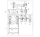
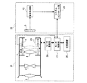
以下、本発明の一実施の形態について、図面を参照しながら説明する。図1は、本発明の一実施の形態に係る撮像装置の概略図及びブロック図である。図1において、1はレンズ鏡筒、19はカメラ本体である。レンズ鏡筒1は撮像レンズ群を備えており、被写体側から順に、第1群レンズである固定レンズ群2、第2群レンズである固定レンズ群3、第3群レンズであるフォーカスレンズ4が配置されている。固定レンズ群2、3はレンズ鏡筒1に固定されている。フォーカスモータであるモータ9とモータ駆動部11とでモータ駆動手段を形成しており、フォーカスレンズ4は、モータ9の回転によって、ねじが切られたリードスクリューに沿って光軸方向に移動し、フォーカスを調整することができる。
Hereinafter, an embodiment of the present invention will be described with reference to the drawings. FIG. 1 is a schematic diagram and a block diagram of an imaging apparatus according to an embodiment of the present invention. In FIG. 1, 1 is a lens barrel and 19 is a camera body. The
モータ9は、図1の例ではモータ駆動部11から出力されるモータコイルの駆動信号(励磁信号)の位相に応じて回転するステッピングモータを示す。5は撮像デバイスである撮像素子であり、固定レンズ群2、3及びフォーカスレンズ4を透過して撮像された被写体の画像を電気信号に変換するものである。7は遮蔽部材であり、フォーカスレンズ4の枠に固定されている。
In the example of FIG. 1, the motor 9 is a stepping motor that rotates in accordance with the phase of the motor coil drive signal (excitation signal) output from the
図1の点線で示すようにフォーカスレンズ4を撮像素子5の方向に移動させて、位置検出センサであるフォトセンサ8を、遮蔽部材7で遮蔽することによって、フォーカスレンズ4の原点位置の検出を行う。
As shown by the dotted line in FIG. 1, the focus lens 4 is moved in the direction of the image sensor 5, and the
12は撮像素子5から出力される電気信号に基づいて画像データやフォーカス調整を行うためのコントラスト情報を生成する信号処理部である。17はレンズ鏡筒1に搭載されたデータ送受信部であり、18はカメラ本体19に搭載されたデータ送受信部である。15は、モータ9のモータ制御手段であるモータ制御部である。フォーカス調整は、信号処理部12で処理された画像に基づいて、ユーザーが行うことができる。また、信号処理部12のコントラスト情報に基づいて、コントラストが最大になるようにフォーカス自動調整(オートフォーカス機能)を行うこともできる。いずれの場合も、モータ制御部15は、データ送受信部17及び18を介して、モータ駆動部11にフォーカスレンズ4の駆動指令を出力する。
A
14は記憶手段である不揮発性メモリ、16は電源であり、モータ駆動部11に印加すべき電圧は、不揮発性メモリ14に記憶されたモータ印加電圧の情報に基づいて設定される。この詳細は後に説明する。20は温度センサ、21はカメラ本体19の姿勢角に応じて出力が変化する角度センサである。これらの各センサの出力は、モータ制御部15に入力され、フォーカスレンズ4の位置補正を行うために用いられる。
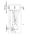
図2は、図1に示したモータ制御部15の詳細ブロック図である。図2において、モータ制御部15は、制御部13、励磁位置カウンタ151及び絶対位置カウンタ153を備えている。励磁位置カウンタ151は、制御部13から出力されるフォーカス移動方向及び移動ステップ情報に基づいて、モータ9の駆動信号の位相を制御し、フォーカスレンズ4の位置制御を行うための励磁位置カウンタのカウントアップ又はカウントダウンを行う。
FIG. 2 is a detailed block diagram of the
前記の図1に示した構成では、フォーカスレンズ4の位置は、モータ9の回転で制御される。また、モータ9の回転は、データ送受信部18及び17を介してモータ制御部15から信号を受けたモータ駆動部11からの周期性のある駆動信号で制御される。
In the configuration shown in FIG. 1, the position of the focus lens 4 is controlled by the rotation of the motor 9. The rotation of the motor 9 is controlled by a periodic drive signal from the
電源投入直後には、制御部13は、詳細は後に説明するが、レンズ鏡筒1に搭載された不揮発性メモリ14に記憶されたレンズ制御関連の情報を読み出した後、フォーカス原点検出処理を行う。フォーカス原点検出処理においては、まず、フォーカスレンズ4が撮像素子5の方向へ駆動される。この駆動が進行すると、遮蔽部材7によってフォトセンサ8が遮蔽される。この遮蔽量に応じて、フォトセンサ8の信号レベルが変化し、所定の条件で閾値を超えたとき(又は回路の構成によっては閾値を下回ったとき)に、絶対位置カウンタ153をリセット又はプリセットする処理を行う。
Immediately after the power is turned on, the
この処理の終了後、モータ制御部15は、データ送受信部18及び17を介してモータ駆動部11にモータ9の制御情報を送信する。モータ駆動部11は、これらの制御情報を受信し、この受信情報に基づいて周期性のある駆動信号を出力し、フォーカスレンズ4の位置制御を行う。モータ制御部15から送信される情報は、図2に示したように励磁位置カウンタ151を介して送信される情報と、制御部13からデータ送受信部18に直接送信される情報とがある。
After the completion of this process, the
励磁位置カウンタ151を介して送信される情報は、フォーカスレンズ4の位置に関する情報である。制御部13は信号処理部12からのコントラスト情報、励磁位置カウンタ151から出力されるモータ9の回転位置情報、絶対位置カウンタ153から出力されるフォーカスレンズ4の位置情報に基づいて、モータ9の移動方向及び移動ステップ情報を励磁位置カウンタ151に出力することによって、フォーカスレンズ4の位置制御を行う。制御部13からデータ送受信部18に直接送信される情報には、例えばモータ9の印加電圧の情報や最大駆動速度に関する情報がある。
Information transmitted via the
なお、絶対位置カウンタ153は、励磁位置カウンタ151のカウンタ値と同期して動作する。励磁位置カウンタ151がモータ9の駆動電気角が1周期(360度)で一巡するカウンタであるのに対して、絶対位置カウンタ153は所定の条件でリセットされた値を基準とした絶対位置を表すカウンタである。
The
レンズ鏡筒1とカメラ本体19との情報の送受信は、データ送受信部17及び18との間で行われ、レンズ鏡筒1とカメラ本体19とを切り離す際には、データ送受信部17と18との接合部(図示せず)、及びモータ駆動部11と電源16との接合部(図示せず)を切り離す。
Information transmission / reception between the
本実施の形態では、フォーカスレンズ4を制御するモータ制御部15を、レンズ鏡筒1内に配置したり、レンズ鏡筒1とカメラ本体19とに分担して配置するのではなく、カメラ本体19内に配置している。このため、不揮発性メモリ14に記憶された情報の制御用としての処理は、レンズ鏡筒1内で行なわれるのではなく、カメラ本体19内のモータ制御部15で行なわれることになる。すなわち、不揮発性メモリ14内の情報は、データ送受信部17、18を経て、モータ制御部15へ送信され、カメラ本体19内で処理され、再びレンズ鏡筒1に送信されることになる。この構成によれば、レンズ鏡筒1内には制御用の大規模なマイコンを設ける必要がなく、レンズ鏡筒1をコンパクトにでき、低コスト化も図れる。レンズ鏡筒1には、データ送受信部17を設けているが、これはレンズ鏡筒1とカメラ本体19との間のデータの受け渡しを主目的としたものであり、簡素な構成で足りることになる。
In the present embodiment, the
図3は、データ送受信部17、18の動作説明図である。「CK」は、「DATA」(ここでは、アドレス、データ1、データ2、及びパリティである。)を検出するためのクロックである。この「CK」を、カメラ本体19のデータ送受信部18から、レンズ鏡筒1のデータ送受信部17へ送信する。データ送受信部17は、各アドレスに対応したデータを不揮発性メモリ14から読み出すことになる。
FIG. 3 is an explanatory diagram of the operation of the data transmitter /
「DE」についても、カメラ本体19のデータ送受信部18からレンズ鏡筒1側のデータ送受信部17へ出力するものである。「DE」が“H”レベルから“L”レベルに変化した直後の8ビットデータを、アドレスとしてデータ送受信部17で認識する。次に、“L”レベル期間におけるアドレス以降の8ビットデータをデータ(ここではデータ1、データ2)としてデータ送受信部17で認識する。
“DE” is also output from the data transmitting / receiving
なお、16ビットのデータはデータ1を上位8ビットのデータとし、データ2を下位8ビットのデータとして送受信を行い、24ビットのデータはデータ1を上位8ビットのデータ、データ2を中位8ビットのデータ、データ3を下位8ビットのデータとして送受信を行う。
Note that 16-bit data is transmitted and received with
次に“L”レベルから“H”レベルに変化した直後の8ビットデータをパリティとする。パリティは、例えば(アドレス)XOR(データ1)XOR(データ2)を演算した値とし、この演算はデータ送受信部17で行い演算値をデータ送受信部18に送信する。モータ制御部15は、データ送受信部18からのデータを受信し、データ送受信部17と同様に(アドレス)XOR(データ1)XOR(データ2)を演算し、受信したパリティと比較して一致しない場合にはデータを再度送信又は再度受信を行う。
Next, 8-bit data immediately after the change from the “L” level to the “H” level is used as the parity. The parity is, for example, a value obtained by calculating (address) XOR (data 1) XOR (data 2). This calculation is performed by the data transmitter /
以下の表1に不揮発性メモリ14に記憶させる情報のうち、撮像装置の通常使用時は読み出すだけの情報(以下、「メモリREAD情報」という。)を示す。メモリREAD情報は、製造工程において不揮発性メモリ14に書き込んだものである。
Table 1 below shows information (hereinafter referred to as “memory READ information”) that can be read out during normal use of the imaging apparatus among information stored in the
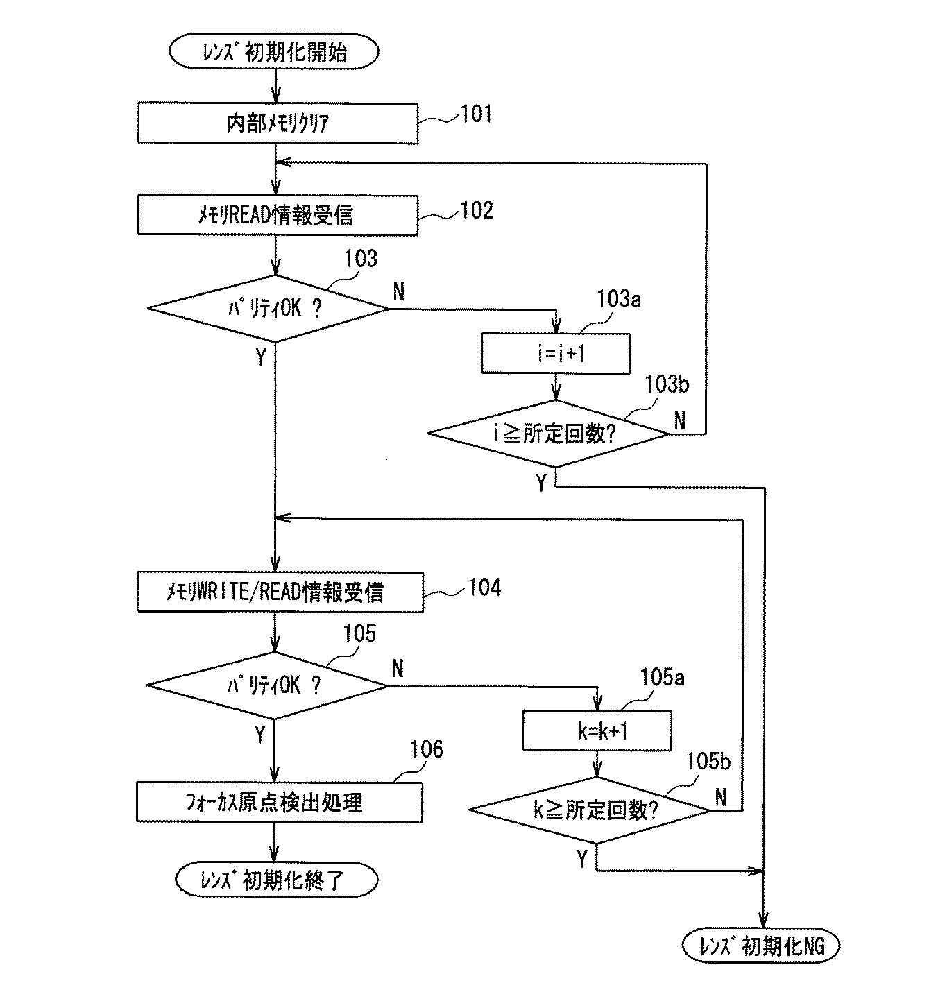
表1に示したように、不揮発性メモリ14に記憶された情報は、複数の各アドレスにデータが対応した情報テーブルを形成している。このことは、以下の表2、3についても同様である。
As shown in Table 1, the information stored in the
表1において、アドレス0x00の「励磁方法」のデータは、ステッピングモータの場合には1相励磁(0x00)、2相励磁(0x01)、1−2相励磁(0x02)などがあり、表1は1−2相励磁(0x02)の場合を示している。 In Table 1, “excitation method” data of address 0x00 includes 1 phase excitation (0x00), 2 phase excitation (0x01), 1-2 phase excitation (0x02), etc. in the case of a stepping motor. The case of 1-2 phase excitation (0x02) is shown.
アドレス0x01の「最大応答周波数」はモータの最大駆動速度に関するものであり、表1の例は1−2相励磁の場合であり、データ0x0DACを10進数に変換して3500[pps]を表す。アドレス0x03の「最大自起動周波数」もモータの最大駆動速度に関するものであり、表1の例は1−2相励磁の場合であり、データ0x2D0を10進数に変換して720[pps]を表す。 “Maximum response frequency” at address 0x01 relates to the maximum drive speed of the motor. The example in Table 1 is for the case of 1-2 phase excitation, and the data 0x0 DAC is converted to a decimal number to represent 3500 [pps]. “Maximum self-starting frequency” at address 0x03 is also related to the maximum driving speed of the motor, and the example in Table 1 is for the case of 1-2 phase excitation. Data 0x2D0 is converted to a decimal number to represent 720 [pps]. .
アドレス0x05の「モータ電流」は、データ0x46を10進数に変換して70[mA]を表す。アドレス0x06の「モータ電圧」は、データ0x32を10進数に変換して50[×10-1V]を表す。このモータ電圧の情報に基づいて制御部13は、電源16にモータ駆動部11の印加電圧を設定させる。
The “motor current” at the address 0x05 represents 70 [mA] by converting the data 0x46 into a decimal number. The “motor voltage” at address 0x06 represents 50 [× 10 −1 V] by converting data 0x32 into a decimal number. Based on the motor voltage information, the
アドレス0x07のフォーカスレンズ単位移動量は、データ0x0Fを10進数に変換して1−2相励磁の場合で15[μm]を表す。アドレス0x08の磁極数は、データ0x0Aを10進数に変換して10[極]を表し、モータ9の駆動信号の1周期は回転角度に換算すると72[度]に相当する。下記のように、モータ9の駆動信号1周期あたりの回転分解能は8[分割]であるので、前記のフォーカスレンズ単位移動量15[μm]は、モータ9の回転角度に換算すると、72/8=9[度]に相当することが分かる。 The focus lens unit movement amount at address 0x07 represents 15 [μm] in the case of 1-2 phase excitation by converting data 0x0F into a decimal number. The number of magnetic poles at the address 0x08 represents 10 [pole] by converting the data 0x0A into a decimal number, and one cycle of the drive signal of the motor 9 corresponds to 72 [degrees] when converted to a rotation angle. As described below, since the rotational resolution per cycle of the drive signal of the motor 9 is 8 [divided], the focus lens unit movement amount 15 [μm] is 72/8 when converted to the rotational angle of the motor 9. = 9 [degrees].
アドレス0x09の回転分解能は、データ0x08を10進数に変換して8[分割]を表し、これはモータ9の駆動信号1周期あたりの回転分解能であり、モータ9の回転角度に換算すると、前記のように72/8=9[度]に相当する。 The rotational resolution of the address 0x09 represents 8 [division] by converting the data 0x08 into a decimal number. This is the rotational resolution per one drive signal cycle of the motor 9, and when converted to the rotational angle of the motor 9, Thus, this corresponds to 72/8 = 9 [degrees].
アドレス0x0Aの焦点距離は、データ0x0023を10進数に変換して35[mm]を表す。アドレス0x0Cの最大使用サイクルは、データ0x0186A0を10進数に変換して100000[サイクル]を表し、例えばフォーカスレンズ4の可動範囲の往復距離分だけモータ9が回転した場合を1[サイクル]として考えた場合の最大使用サイクルを表す。アドレス0x0Fの基準励磁位置は後述するが工程調整時に行われたモータ9の基準励磁位置を表す。 The focal length of the address 0x0A represents 35 [mm] by converting the data 0x0023 into a decimal number. The maximum use cycle of the address 0x0C represents 100000 [cycle] by converting the data 0x0186A0 into a decimal number. For example, the case where the motor 9 is rotated by the reciprocating distance of the movable range of the focus lens 4 is considered as 1 [cycle]. Represents the maximum use cycle. The reference excitation position of the address 0x0F represents the reference excitation position of the motor 9 performed at the time of process adjustment, which will be described later.
アドレス0x10の被写体距離∞−フォーカス位置は、撮像素子5から被写体までの距離が∞の場合におけるフォーカスレンズ4の位置を絶対位置カウンタ153の値で表したものである。アドレス0x12、アドレス0x14、アドレス0x16は、被写体までの距離∞の場合と同様に、撮像素子5から被写体までの距離が2m、1m、0.5mにおける絶対位置カウンタ153のカウンタ値である。
The subject distance ∞−focus position at address 0x10 represents the position of the focus lens 4 when the distance from the image sensor 5 to the subject is ∞ by the value of the
各データは原点位置を0とした絶対値カウンタ153の値を示している。アドレス0x10の被写体距離∞−フォーカス位置では、0x0198を10進数に変換して408となる。アドレス0x12の被写体距離2m−フォーカス位置では、0x01BAを10進数に変換して442となる。アドレス0x14の被写体距離1m−フォーカス位置では、0x01D9を10進数に変換して473となる。アドレス0x16の被写体距離0.5m−フォーカス位置では、0x0213を10進数に変換して531となる。
Each data indicates the value of the
このように、本実施の形態に係るレンズ鏡筒1は、モータ9の回転角度と被写体距離との関係を明確にしたデータをレンズ鏡筒1内に備えていることになる。交換レンズとして、複数種類のレンズ鏡筒1を用意した場合、各レンズ鏡筒1のそれぞれの不揮発性メモリ14に前記各データに相当するデータを記憶させておけば、フォーカスレンズ位置の制御をレンズ鏡筒1の種類に関係なく精度よく行うことができることになる。
As described above, the
アドレス0x18の温度によるフォーカス位置補正量は、絶対値カウンタ153の値で10℃変化での補正量を表し、データ0x06を10進数に変換して6となる。アドレス0x19の姿勢角度によるフォーカス位置補正量は、絶対値カウンタ153の値で90°変化での補正量を表し、データ0x1Fを10進数に変換して31となる。これらの温度、姿勢角度による補正については、後に詳細を説明する。
The focus position correction amount based on the temperature at the address 0x18 is the value of the
以下の表2に、不揮発性メモリ14に記憶させる情報のうち、撮像装置の通常使用時に読み出し及び書き込み動作を行う情報(以下、「メモリWRITE/READ情報」という。)を示す。前記の表1の各アドレスに対応したデータは、書き込みを製造工程において行ない、読み出しを通常使用時に行なうものであるが、表2の各アドレスに対応したデータは、通常使用時に読み出しと書き込みの双方行うものである。
Table 2 below shows information (hereinafter referred to as “memory WRITE / READ information”) that performs reading and writing operations during normal use of the imaging apparatus among information stored in the
ここでは、8ビットのアドレスの最上位ビットが“1”の場合は、不揮発性メモリ14にデータを書き込む場合、最上位ビットが“0”の場合は、不揮発性メモリ14からデータを読み出す場合とし、以下では書き込みアドレス/読み出しアドレスとして説明する。
Here, when the most significant bit of the 8-bit address is “1”, data is written to the
表2において、アドレス0x90/0x10の使用サイクルは、例えばフォーカスレンズ4の可動範囲の往復距離分だけモータ9が回転した場合を1[サイクル]とした場合の使用サイクルを表す。 In Table 2, the use cycle of the address 0x90 / 0x10 represents a use cycle when the motor 9 is rotated by the reciprocating distance of the movable range of the focus lens 4 as 1 [cycle].
この1サイクルの基準を、フォーカス位置が原点から最も遠くなる被写体距離0.5mの場合とすると、この場合のフォーカス位置は、前記のようにカウンタ値が531すなわち原点から531分だけ離れた位置であるので、往復距離は531×2=1062となる。したがって、1062分カウントされた場合に、読み出した使用サイクルに+1[サイクル]を加算することにより、モータ9の使用サイクルを管理することが可能になる。 If the reference for this one cycle is a subject distance of 0.5 m, which is the farthest from the origin, the focus position in this case is the position where the counter value is 531, that is, the position 531 minutes away from the origin as described above. Therefore, the round trip distance is 531 × 2 = 1062. Therefore, when the count is 1062 minutes, the use cycle of the motor 9 can be managed by adding +1 [cycle] to the read use cycle.
この場合、制御部13において使用サイクルを管理し、電源終了直前にデータ送受信部18及び17を介して不揮発性メモリ14に使用サイクルを書き込むことによって最新の使用サイクルに更新することができる。
In this case, it is possible to update the latest use cycle by managing the use cycle in the
以下の表3に、データ送受信部17と18との間で送受信する制御情報を示す。
Table 3 below shows control information transmitted / received between the data transmitting / receiving
表3において、アドレス0x20のフォトセンサ出力レベルは、フォーカスレンズ4が撮像素子5の方向へ駆動され、遮蔽部材7によってフォトセンサ8が遮蔽されることで変化する出力レベルである。フォトセンサ8の信号レベルが変化し、所定の条件で閾値を超えたとき(又は回路の構成によっては閾値を下回ったとき)に、不揮発性メモリ14に記憶されていたデータは例えば0x00から0x01に変化する。
In Table 3, the photosensor output level at address 0x20 is an output level that changes as the focus lens 4 is driven in the direction of the image sensor 5 and the
アドレス0xA0のモータ励磁位置はモータ9の励磁位置を表し、例えばモータ9の駆動信号の1周期を1−2相励磁として8分割したとすると、0x00,0x01,・・・0x07の8つの値で表すことができる。ここでは、0x04の励磁位置を表しており、励磁位置カウンタ151の出力値である。
The motor excitation position of the address 0xA0 represents the excitation position of the motor 9. For example, if one cycle of the drive signal of the motor 9 is divided into eight as 1-2 phase excitation, eight values of 0x00, 0x01,. Can be represented. Here, the excitation position of 0x04 is shown, which is the output value of the
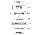
次に、通常使用モードで電源投入時におけるレンズ初期化動作について説明する。図4はレンズ初期化動作フローチャートである。このフローチャートは、制御部13における処理プログラムによる動作を示す。ステップ101では、制御部13の内部メモリをクリアする。ステップ102では、レンズ鏡筒1に搭載された不揮発性メモリ14に記憶されたメモリREAD情報を受信する。
Next, the lens initialization operation when the power is turned on in the normal use mode will be described. FIG. 4 is a flowchart of the lens initialization operation. This flowchart shows the operation by the processing program in the
ステップ103では、前記のように受信したパリティと制御部13で演算したパリティとの比較確認を行い、各パリティが一致するかどうかを判定する。一致していれば次のステップ104に進み、一致していなければステップ103aに進む。ステップ103aでは変数i(初期値は0)を1加算してステップ3bに進み、ステップ103bでは変数iが所定回数(例えば3)以上かどうかを判定する。変数iが所定回数に満たない場合にはステップ2に戻り、同様の動作を行う。変数iが所定回数に達した場合にはレンズ初期化NGとしてレンズ初期化動作を終了する。
In
ステップ104では、不揮発性メモリ14に記憶されたメモリWRITE/READ情報を受信する。ステップ105では前記のように受信したパリティと制御部13で演算したパリティとの比較確認を行い、各パリティが一致するかどうかを判定する。一致していれば次のステップ106に進み、一致していなければステップ105aに進む。
In
ステップ105aでは、変数k(初期値は0)を1加算してステップ105bに進み、ステップ105bでは変数kが所定回数(例えば3)以上かどうかを判定する。変数が所定回数に満たない場合にはステップ104に戻り、同様の動作を行う。変数kが所定回数に達した場合にはレンズ初期化NGとしてレンズ初期化動作を終了する。ステップ106ではフォーカス原点検出処理を行い、レンズ初期化動作を終了する。
In
レンズ初期化動作の終了後は、不揮発性メモリ14から受信したメモリREAD情報に基いて通常動作が行なわれ、通常動作終了後は、メモリWRITE/READ情報が新たな情報に更新されていることになる。
After completion of the lens initialization operation, normal operation is performed based on the memory READ information received from the
また、レンズ鏡筒1を新たなレンズ鏡筒1に交換した場合には、前記の図4に示したステップを経て、制御部13は新たなレンズ鏡筒1に対応した情報を受信することになる。
When the
したがって、レンズ鏡筒1を交換した場合でも交換後のレンズ鏡筒1に搭載されたモータ9及びフォーカスレンズ4の動作条件に合わせて、カメラ本体19のフォーカス制御部15によって、フォーカスレンズ4の位置の制御を行うことが可能になる。不揮発性メモリ14に記憶された各情報については、前記の表1−3を用いて説明した通りであるが、表1−3を参照しながら、以下説明を補足する。
Therefore, even when the
モータの磁極数の情報を用いることで、駆動信号の1周期に対するモータの回転角度の関係が分かり、種々のモータの回転制御が可能になる。また、回転分解能(移動距離分解能)が高いモータを搭載しているレンズ鏡筒では、回転分解能の情報を用いることで、フォーカスレンズの駆動ピッチをモータに合わせて高精度に制御することも可能になり、表1では8[分割]の例を示したが、64[分割]などのマイクロステップのモータにも対応が可能となる。 By using information on the number of magnetic poles of the motor, the relationship of the rotation angle of the motor with respect to one cycle of the drive signal can be understood, and various motor rotation controls can be performed. In addition, in lens barrels equipped with motors with high rotational resolution (moving distance resolution), it is possible to control the focus lens drive pitch with high accuracy by using the rotational resolution information. Thus, in Table 1, an example of 8 [division] is shown, but it is possible to deal with a microstep motor such as 64 [division].
また、モータの印加電圧の情報を用いることで、種々のモータ及び駆動回路に対応して印加電圧を設定することが可能になる。また、モータ最大応答周波数や最大自起動周波数などの最大駆動速度の情報を用いることで、種々のモータに対応してフォーカスを最大速度で制御することが可能になる。 Further, by using the information on the applied voltage of the motor, it becomes possible to set the applied voltage corresponding to various motors and driving circuits. Further, by using information on the maximum driving speed such as the maximum motor response frequency and the maximum self-starting frequency, the focus can be controlled at the maximum speed corresponding to various motors.
また、表2のように、メモリWRITE/READ情報として、使用サイクルの情報を備えており、これをレンズ鏡筒1のモータ9の交換時期などのメンテナンスに関する情報として利用することができる。例えば、表1に示した最大使用サイクルの情報と比較することにより、モータ9の交換時期を判断できるので、交換時期になるとこのことを表示させるようにしてもよい。また、メンテナンスに関しては、使用サイクルの情報に限らず、使用時間の情報を利用してもよい。
Further, as shown in Table 2, use cycle information is provided as memory WRITE / READ information, which can be used as information related to maintenance such as the replacement time of the motor 9 of the
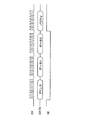
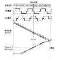
次に、工程調整における表1のアドレス0x0Fの基準励磁位置について、図5を参照しながら説明する。図5は、本発明の一実施の形態に係る工程調整時の原点検出動作の説明図である。図5に表示した「励磁位置」は、駆動信号の位相に対応しており、モータ9にモータ駆動部11から出力されるモータコイルの駆動信号の1周期360度を8分割して励磁位置カウンタ151の3ビットのカウンタ値として表現している。
Next, the reference excitation position at address 0x0F in Table 1 in the process adjustment will be described with reference to FIG. FIG. 5 is an explanatory diagram of an origin detection operation during process adjustment according to an embodiment of the present invention. The “excitation position” displayed in FIG. 5 corresponds to the phase of the drive signal, and the excitation position counter is obtained by dividing one cycle 360 degrees of the drive signal of the motor coil output from the
励磁位置カウンタ151のカウンタ値は、データ送受信部18及び17を介してモータ駆動部11に送信される。ここでは、フォーカスレンズ4が撮像素子5側へ移動するにつれて、励磁位置が1ずつ減算していく様子を示しており、アドレス0xA0(表3)としてモータ励磁位置を転送することにより、モータ9の回転を制御する。
The counter value of the
「A相電流」及び「B相電流」は、モータ9にモータ駆動部11から出力されるモータコイルの電流波形で、モータ9がA相とB相の2相コイルを有している例を示している。A相電流及びB相電流は互いに電気角(電流波形の1周期を360度とした場合)で90度位相が異なるようにしており、A相とB相のモータコイルに電流を印加することでモータ9を回転させる。ここでは、A相電流がB相電流に対して90度位相が進んでいる条件で、フォーカスレンズ4が撮像素子5側へ移動するようにしている。
“A-phase current” and “B-phase current” are current waveforms of the motor coil output from the
「絶対位置カウンタ」は、絶対位置カウンタ153のカウンタ値を表しており、励磁位置に同期して動作する。励磁位置が1ずつ減算していく場合には、絶対位置カウンタも同様に1ずつ減算していく。ただし、絶対位置カウンタは、フォーカスレンズ4の移動範囲において同じ値が存在しないようにビット幅を設定する。
The “absolute position counter” represents the counter value of the
「フォトセンサ出力レベル」は、フォーカスレンズ4が撮像素子5の方向へ移動し、遮蔽部材7によってフォトセンサ8が遮蔽されることで出力レベルが変化していく様子を示している。「フォトセンサ出力レベル」は、閾値以上の場合に“1”、閾値未満の場合に“0”として、制御部13においてアドレス0x20(表3)のデータをデータ送受信部17及び18を介して識別する。
“Photo sensor output level” indicates a state in which the output level changes as the focus lens 4 moves in the direction of the image sensor 5 and the
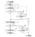
次に、図5、図6を参照しながら工程調整におけるフォーカスレンズ4の原点検出動作について、具体的に説明する。図6は、本発明の一実施の形態に係る原点検出動作フローチャートであり、制御部13にプログラミングされている動作フローを示す。工程調整モードで電源投入時に「原点検出調整スタート」から処理を行う。
Next, the origin detection operation of the focus lens 4 in the process adjustment will be specifically described with reference to FIGS. FIG. 6 is an origin detection operation flowchart according to an embodiment of the present invention, and shows an operation flow programmed in the
ステップ201において、原点検出方向(撮像素子5方向)へモータ9を1ステップずつ移動させる。この場合、励磁位置カウンタ151は、1ずつ減算されることになる。より具体的には、制御部13からの指令により励磁位置カウンタ151をダウンカウントする。モータ駆動部11では、このダウンカウントに従って、周期性のある駆動信号を出力し、撮像素子5の方向へモータ9を回転させることによってフォーカスレンズ4を移動させる。
In
ステップ202において、フォトセンサ出力レベルが閾値を超えているかどうかを判定する。超えていない場合には、ステップ201に戻って、モータ9に次の1ステップ動作をさせる。超えている場合にはステップ203に進み、超えた時点の励磁位置をPに代入する。ここでは、励磁位置「4」をPに代入する。
In
ステップ204では、Pを不揮発性メモリ14にPoとして記憶させる。ここで記憶させた値Poがモータ9の基準励磁位置であり、アドレス0x0F、データ0x04として、データ送受信部18及びデータ送受信部17を介して不揮発性メモリ14に記憶させる。ステップ205では、絶対位置カウンタをリセットする。図5において「0」で示した位置がリセットされた位置となる。
In
この絶対位置カウンタの「0」の位置は、電源を切ると消去されてしまうので、通常使用モードの電源投入時には、再び原点位置を検出する必要がある。この原点位置の検出に、不揮発性メモリ14に記憶させた基準励磁位置「4」の情報を用いる。励磁位置「4」は絶対位置ではなく、周期的に現れる位置であるので、原点に対応した励磁位置「4」を検出すれば、原点位置を検出できることになる。
Since the position “0” of the absolute position counter is erased when the power is turned off, it is necessary to detect the origin position again when the power is turned on in the normal use mode. Information on the reference excitation position “4” stored in the
具体的には、通常使用モードにおいて、モータ制御部15からの信号により、モータ9を原点検出方向に回転させる。この場合、すでに不揮発性メモリ14から受信した基準励磁位置「4」からモータ9の電気角180度(1/2周期)離れた励磁位置「0」においてフォトセンサ出力レベルが閾値を越えたかどうかを判定する。ある判定位置「0」におけるフォトセンサ出力レベルが閾値を越えておらず、1周期後の次の判定位置「0」のフォトセンサ出力レベルが閾値を越えていることを検出できれば、工程調整時の原点位置を正確に再現することができる。すなわち、この2つの判定位置「0」の間における励磁位置「4」が原点位置になる。
Specifically, in the normal use mode, the motor 9 is rotated in the origin detection direction by a signal from the
この原点検出処理は、原点位置を直接検出する必要はなく、前記のように、ある判定位置におけるフォトセンサ出力レベルが閾値を越えておらず、次の判定位置のフォトセンサ出力レベルが閾値を越えていることが検出できればよい。このため、レンズユニット駆動方向のガタ、使用環境温度・湿度変化による機構・電気特性ばらつきなどの誤差を生じた場合でも工程調整時の原点位置を正確に再現することができる。 This origin detection process does not require direct detection of the origin position. As described above, the photosensor output level at a certain judgment position does not exceed the threshold value, and the photosensor output level at the next judgment position exceeds the threshold value. It is sufficient if it can be detected. For this reason, the origin position at the time of process adjustment can be accurately reproduced even if errors such as play in the lens unit driving direction, mechanism / electrical characteristic variations due to changes in operating environment temperature / humidity, and the like occur.
ただし、レンズユニット駆動方向のガタ、使用環境温度・湿度変化による機構・電気特性ばらつきなどの誤差の幅は励磁位置1周期の範囲に抑える必要がある。 However, it is necessary to limit the range of errors such as play in the lens unit driving direction, mechanism / electrical characteristic variation due to changes in operating environment temperature / humidity, and the like within the range of one excitation position.
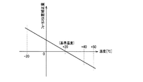
次に、不揮発性メモリ14に記憶されている温度によるフォーカス位置補正量を用いたフォーカスレンズ4の制御方法について説明する。図7は温度とフォーカス位置補正量との関係を示すグラフである。表1におけるアドレス0x18のデータは0x06であり、温度が10℃変化した場合に絶対位置カウンタ153のカウンタ値が6変化する。ここでの例は、温度上昇に伴ってフォーカスレンズ4の位置を撮像素子5に近づく方向(遠側)に移動させて補正する例であり、20℃を基準とした−0.6[カウンタ/℃]の傾きを持った直線のグラフで表すことができる。
Next, a method for controlling the focus lens 4 using the focus position correction amount based on the temperature stored in the
図2に示したように、制御部13は温度センサ20からの情報を受信する。制御部13では、温度センサ20で検出された温度変化及びアドレス0x18のデータは0x06に基づいて、先のグラフに従ってフォーカスレンズ4の位置を補正することによって温度変化を生じた場合においても合焦状態を保つことが可能になる。
As shown in FIG. 2, the
例えば、使用時における温度が基準温度である20℃の場合は、フォーカスレンズ4のフォーカス位置は補正されない。一方、基準温度より10℃高い30℃になると、フォーカス位置は、撮像素子5に近づく方向にカウンタ値が6だけ変化した位置に補正されることになる。 For example, when the temperature during use is 20 ° C. which is the reference temperature, the focus position of the focus lens 4 is not corrected. On the other hand, when the temperature becomes 30 ° C., which is 10 ° C. higher than the reference temperature, the focus position is corrected to a position where the counter value has changed by 6 in the direction approaching the image sensor 5.
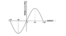
次に、不揮発性メモリ14に記憶されている姿勢角度によるフォーカス位置補正量を用いたフォーカスレンズ4の制御方法について説明する。図8は姿勢角度と角度センサ出力電圧との関係を示すグラフである。表1におけるアドレス0x19のデータは0x1Fであり、姿勢角度が90度変化した場合に絶対位置カウンタ153のカウンタ値が31変化する。
Next, a method for controlling the focus lens 4 using the focus position correction amount based on the attitude angle stored in the
ここでは、固定レンズ2が上向く方向では角度センサ出力電圧が+になり、固定レンズ2が下向く方向では角度センサ出力電圧が−になるものとする。例えば、上向き90度では機構系のガタによってフォーカスレンズ4は撮像素子5に近づく方向に絶対値カウンタ153のカウンタ値で31変化し、下向き90度では機構系のガタによってフォーカスレンズ4は撮像素子5から遠ざかる方向に絶対値カウンタ153のカウンタ値で31変化するものとする。
Here, it is assumed that the angle sensor output voltage is + when the fixed lens 2 is upward, and the angle sensor output voltage is − when the fixed lens 2 is downward. For example, at an upward angle of 90 degrees, the focus lens 4 changes by 31 in the counter value of the
図2に示したように、制御部13は角度センサ21からの情報を受信する。この場合、例えば上向き90度では、制御部13は角度センサ21で検出された角度変化及びアドレス0x19のデータは0x1Fに基づいて、フォーカスレンズ4の位置を撮像素子5から遠ざかる方向にカウンタ値31分補正する。一方、下向き90度ではフォーカスレンズ4の位置を撮像素子5に近づく方向にカウンタ値31分補正する。このことにより、大きな姿勢角度変化を生じた場合においても合焦状態を保つことが可能になる。
As shown in FIG. 2, the
なお、水平時に対して上向き方向と下向き方向とでフォーカスレンズ位置4のガタが異なる場合には、メモリREAD情報として記憶させるエリアを別々に有してもよい。 In addition, when the play of the focus lens position 4 is different between the upward direction and the downward direction with respect to the horizontal direction, an area to be stored as memory READ information may be provided separately.
また、ここでは温度センサと角度センサを用いた例を示したが、さらに湿度センサを用いてもよい。この構成によれば、レンズ鏡筒やレンズなどの吸湿係数の違いで生じる誤差を改善することができ、さらに精度を向上させることができる。 Although an example using a temperature sensor and an angle sensor is shown here, a humidity sensor may be used. According to this configuration, an error caused by a difference in moisture absorption coefficient between the lens barrel and the lens can be improved, and the accuracy can be further improved.
また、本実施の形態では、駆動手段としてステッピングモータの例で説明したが、モータの駆動信号に周期性を有するモータであればよく、例えばリニアモータなどでもよい。 In the present embodiment, the stepping motor has been described as an example of the driving unit. However, any motor having a periodicity in the driving signal of the motor may be used. For example, a linear motor may be used.
さらに、モータの移動量を検出する回路を設けることで、位置に応じて本実施の形態における励磁位置カウンタをカウントアップ又はカウントダウンすることによって、駆動信号に周期性を擬似的につくることで超音波モータ、スムーズインパクト駆動機構で構成されるモータ、静電モータ、圧電モータなどの各種モータに本発明を適用可能である。 Furthermore, by providing a circuit that detects the amount of movement of the motor, the excitation position counter in the present embodiment is counted up or down according to the position, thereby creating a periodicity in the drive signal, thereby generating ultrasonic waves. The present invention can be applied to various motors such as a motor, a motor composed of a smooth impact drive mechanism, an electrostatic motor, and a piezoelectric motor.
また、本実施の形態においては、フォーカスレンズを駆動するモータについて主に説明したが、ズームレンズを駆動するモータを有する撮像装置及びレンズ鏡筒にも本発明を適用可能である。 In the present embodiment, the motor for driving the focus lens has been mainly described. However, the present invention can also be applied to an imaging apparatus and a lens barrel having a motor for driving a zoom lens.
本発明によれば、レンズ鏡筒のコンパクト化及び低コスト化を実現し、かつレンズ鏡筒の機構・電気特性等のばらつきによるフォーカス位置誤差の発生を防止することができるので、例えば、交換レンズ式のスチルカメラやビデオムービー、又はこれらに用いる交換レンズやカメラ本体として有用である。 According to the present invention, it is possible to reduce the size and cost of the lens barrel and prevent the occurrence of a focus position error due to variations in the mechanism and electrical characteristics of the lens barrel. It is useful as a still camera or video movie of the type, or an interchangeable lens or camera body used for these.
1 レンズ鏡筒
2,3 固定レンズ
4 フォーカスレンズ
5 撮像素子
7 フォトセンサ遮蔽部材
8 フォトセンサ
9 モータ
11 モータ駆動部
12 信号処理部
14 不揮発性メモリ
15 モータ制御部
16 電源
17 データ送受信部
18 データ送受信部
19 カメラ本体
20 温度センサ
21 角度センサ
DESCRIPTION OF
Claims (19)
前記レンズ鏡筒は、
フォーカスレンズを含み被写体を結像する撮像レンズ群と、
前記フォーカスレンズを光軸方向に移動させるモータを含むモータ駆動手段と、
前記フォーカスレンズの制御情報を含む情報テーブルが記憶された記憶手段と、
前記記憶手段から出力される情報を前記カメラ本体に送信する第1のデータ送受信手段とを備えており、
前記カメラ本体は、
前記撮像レンズ群による被写体光を撮像する撮像デバイスと、
前記第1のデータ送受信手段から送信される情報を受信する第2のデータ送受信手段と、
前記第2のデータ送受信手段から出力される受信情報に基づいて前記モータを制御するモータ制御手段とを備えており、
前記フォーカスレンズは、前記モータ制御手段が前記第2のデータ送受信手段を介して前記第1のデータ送受信手段に送信した情報に基づいて制御されること特徴とする撮像装置。 An imaging device in which the lens barrel and the camera body can be separated,
The lens barrel is
An imaging lens group that includes a focus lens and images a subject;
Motor drive means including a motor for moving the focus lens in the optical axis direction;
Storage means for storing an information table including control information of the focus lens;
First data transmission / reception means for transmitting information output from the storage means to the camera body,
The camera body is
An imaging device for imaging subject light by the imaging lens group;
Second data transmitting / receiving means for receiving information transmitted from the first data transmitting / receiving means;
Motor control means for controlling the motor based on reception information output from the second data transmission / reception means,
The imaging apparatus, wherein the focus lens is controlled based on information transmitted from the motor control unit to the first data transmitting / receiving unit via the second data transmitting / receiving unit.
前記レンズ鏡筒は、前記フォーカスレンズの位置に応じて出力値が変化する位置検出センサをさらに備え、
前記モータ制御手段は、前記位置検出センサの出力値が閾値に到達したときの前記駆動信号の位相を前記フォーカスレンズの基準位置として求め、前記基準位置の情報を、前記第2及び第1のデータ送受信手段を介して転送し、前記記憶手段の前記情報テーブルの情報として記憶させる請求項1に記載の撮像装置。 The motor drive means outputs a periodic drive signal based on the received information output from the motor control means, and the motor moves the focus lens in the optical axis direction according to the output drive signal. Move
The lens barrel further includes a position detection sensor whose output value changes according to the position of the focus lens,
The motor control means obtains the phase of the drive signal when the output value of the position detection sensor reaches a threshold value as a reference position of the focus lens, and uses the second and first data as the reference position information. The imaging apparatus according to claim 1, wherein the imaging device is transferred via a transmission / reception unit and stored as information in the information table of the storage unit.
前記モータ駆動手段を駆動する駆動信号に同期したタイミングでかつ前記判定位置で前記第1及び第2のデータ送受信手段を介して前記位置検出センサの出力値を検出し、前記判定位置における前記位置検出センサの出力値が前記閾値に到達しているかどうかを判定して、前記基準位置を再び求める請求項2に記載の撮像装置。 The motor control means obtains a position added or subtracted from the reference position read from the storage means via the first and second data transmission / reception means as a determination position,
The output value of the position detection sensor is detected via the first and second data transmission / reception means at the determination position at a timing synchronized with a drive signal for driving the motor driving means, and the position detection at the determination position is performed. The imaging apparatus according to claim 2, wherein it is determined whether an output value of the sensor has reached the threshold value, and the reference position is obtained again.
前記フォーカスレンズの制御情報を含む情報テーブルが記憶された記憶手段と、
前記記憶手段から出力される情報を、前記カメラ本体に送信する第1のデータ送受信手段とを備え、
前記レンズ鏡筒は、前記フォーカスレンズを制御する情報を第2のデータ送受信手段を介して出力するモータ制御手段を含むカメラ本体に用いるレンズ鏡筒であり、
前記フォーカスレンズは、前記モータ制御手段が前記第2のデータ送受信手段を介して前記第1のデータ送受信手段に送信した情報に基づいて制御されること特徴とするレンズ鏡筒。 A lens barrel including an imaging lens group that includes a focus lens and forms an image of a subject; and a motor driving unit that includes a motor that moves the focus lens in the optical axis direction;
Storage means for storing an information table including control information of the focus lens;
First data transmission / reception means for transmitting information output from the storage means to the camera body;
The lens barrel is a lens barrel used in a camera body including a motor control unit that outputs information for controlling the focus lens via a second data transmission / reception unit,
The focus lens is controlled based on information transmitted from the motor control means to the first data transmission / reception means via the second data transmission / reception means.
前記モータを周期性のある駆動信号で駆動させ、前記駆動信号に応じて前記フォーカスレンズを光軸方向に移動させたときにおいて、
前記位置検出センサの出力値が閾値に到達したときの前記駆動信号の位相を前記フォーカスレンズの基準位置とし、前記基準位置の情報が前記記憶手段の前記情報テーブルの情報として記憶されている請求項11に記載のレンズ鏡筒。 The lens barrel further includes a position detection sensor whose output value changes according to the position of the focus lens,
When the motor is driven with a periodic drive signal and the focus lens is moved in the optical axis direction according to the drive signal,
The phase of the drive signal when the output value of the position detection sensor reaches a threshold is set as a reference position of the focus lens, and information on the reference position is stored as information in the information table of the storage means. The lens barrel according to 11.
前記撮像レンズ群による被写体光を撮像する撮像デバイスと、前記第1のデータ送受信手段から送信される情報を受信する第2のデータ送受信手段と、前記第2のデータ送受信手段から出力される受信情報に基づいて前記モータを制御するモータ制御手段とを備えており、
前記モータ制御手段は、前記第2のデータ送受信手段を介して前記第1のデータ送受信手段に前記フォーカスレンズを制御する情報を送信することを特徴とするカメラ本体。 An imaging lens group that includes a focus lens and forms an object; a motor drive unit that includes a motor that moves the focus lens in the optical axis direction; and a storage unit that stores an information table including control information of the focus lens; A camera body used for a lens barrel provided with first data transmitting / receiving means for transmitting information output from the storage means to the camera body,
An imaging device for imaging subject light by the imaging lens group, a second data transmission / reception unit for receiving information transmitted from the first data transmission / reception unit, and reception information output from the second data transmission / reception unit Motor control means for controlling the motor based on
The camera main body, wherein the motor control means transmits information for controlling the focus lens to the first data transmitting / receiving means via the second data transmitting / receiving means.
Priority Applications (6)
| Application Number | Priority Date | Filing Date | Title |
|---|---|---|---|
| JP2004110280A JP2005292659A (en) | 2004-04-02 | 2004-04-02 | Imaging apparatus, lens barrel used in the imaging apparatus and camera body |
| PCT/JP2004/018395 WO2005057265A1 (en) | 2003-12-09 | 2004-12-09 | Lens driver, imaging device, lens barrel used in the imaging device, and camera body |
| CN2007101600811A CN101241220B (en) | 2003-12-09 | 2004-12-09 | Lens driving apparatus, imaging apparatus, and lens barrel and camera main body used for the imaging apparatus |
| US10/576,944 US7574126B2 (en) | 2003-12-09 | 2004-12-09 | Lens driving apparatus, imaging apparatus, and lens barrel and camera main body used for this |
| US12/496,327 US7801435B2 (en) | 2003-12-09 | 2009-07-01 | Lens driving apparatus, imaging apparatus, and lens barrel and camera main body used for this |
| US12/857,229 US7885529B2 (en) | 2003-12-09 | 2010-08-16 | Lens driving apparatus, imaging apparatus, and lens barrel and camera main body used for this |
Applications Claiming Priority (1)
| Application Number | Priority Date | Filing Date | Title |
|---|---|---|---|
| JP2004110280A JP2005292659A (en) | 2004-04-02 | 2004-04-02 | Imaging apparatus, lens barrel used in the imaging apparatus and camera body |
Publications (1)
| Publication Number | Publication Date |
|---|---|
| JP2005292659A true JP2005292659A (en) | 2005-10-20 |
Family
ID=35325616
Family Applications (1)
| Application Number | Title | Priority Date | Filing Date |
|---|---|---|---|
| JP2004110280A Withdrawn JP2005292659A (en) | 2003-12-09 | 2004-04-02 | Imaging apparatus, lens barrel used in the imaging apparatus and camera body |
Country Status (1)
| Country | Link |
|---|---|
| JP (1) | JP2005292659A (en) |
Cited By (11)
| Publication number | Priority date | Publication date | Assignee | Title |
|---|---|---|---|---|
| JP2009153101A (en) * | 2007-11-28 | 2009-07-09 | Sanyo Electric Co Ltd | Semiconductor device and imaging device |
| JP2009153100A (en) * | 2007-11-28 | 2009-07-09 | Sanyo Electric Co Ltd | Semiconductor device and imaging device |
| JP2009152541A (en) * | 2007-11-28 | 2009-07-09 | Sanyo Electric Co Ltd | Semiconductor device and imaging device |
| JP2010079250A (en) * | 2008-08-28 | 2010-04-08 | Panasonic Corp | Lens barrel and image pickup apparatus |
| EP2570837A3 (en) * | 2011-09-13 | 2013-07-31 | Canon Kabushiki Kaisha | Optical apparatus |
| US8553098B2 (en) | 2007-11-28 | 2013-10-08 | Sanyo Semiconductor Co., Ltd. | Semiconductor device and imaging capturing apparatus |
| WO2014147912A1 (en) * | 2013-03-19 | 2014-09-25 | 富士フイルム株式会社 | Camera device, camera body, interchangeable lens, and method for controlling operation of camera body |
| JP2016085423A (en) * | 2014-10-29 | 2016-05-19 | キヤノン株式会社 | Imaging accessory, imaging apparatus, and communication control program |
| JP2017215574A (en) * | 2016-05-31 | 2017-12-07 | キヤノン株式会社 | Lens controller and control method thereof |
| JP2021051196A (en) * | 2019-09-25 | 2021-04-01 | 株式会社ニコン | Imaging apparatus, imaging lens, camera body, and method for correction |
| JP2021081611A (en) * | 2019-11-20 | 2021-05-27 | キヤノン株式会社 | Imaging apparatus, control method of imaging apparatus, and program |
-
2004
- 2004-04-02 JP JP2004110280A patent/JP2005292659A/en not_active Withdrawn
Cited By (16)
| Publication number | Priority date | Publication date | Assignee | Title |
|---|---|---|---|---|
| JP2009153100A (en) * | 2007-11-28 | 2009-07-09 | Sanyo Electric Co Ltd | Semiconductor device and imaging device |
| JP2009152541A (en) * | 2007-11-28 | 2009-07-09 | Sanyo Electric Co Ltd | Semiconductor device and imaging device |
| US8553098B2 (en) | 2007-11-28 | 2013-10-08 | Sanyo Semiconductor Co., Ltd. | Semiconductor device and imaging capturing apparatus |
| JP2009153101A (en) * | 2007-11-28 | 2009-07-09 | Sanyo Electric Co Ltd | Semiconductor device and imaging device |
| JP2010079250A (en) * | 2008-08-28 | 2010-04-08 | Panasonic Corp | Lens barrel and image pickup apparatus |
| EP2570837A3 (en) * | 2011-09-13 | 2013-07-31 | Canon Kabushiki Kaisha | Optical apparatus |
| US10036872B2 (en) | 2013-03-19 | 2018-07-31 | Fujifilm Corporation | Camera apparatus, camera body, interchangeable lens, and method of controlling operation of camera body |
| WO2014147912A1 (en) * | 2013-03-19 | 2014-09-25 | 富士フイルム株式会社 | Camera device, camera body, interchangeable lens, and method for controlling operation of camera body |
| JP5859708B2 (en) * | 2013-03-19 | 2016-02-10 | 富士フイルム株式会社 | Camera device, camera body, interchangeable lens, and camera body operation control method |
| US9606422B2 (en) | 2013-03-19 | 2017-03-28 | Fujifilm Corporation | Camera apparatus, camera body, interchangeable lens, and method of controlling operation of camera body |
| JP2016085423A (en) * | 2014-10-29 | 2016-05-19 | キヤノン株式会社 | Imaging accessory, imaging apparatus, and communication control program |
| JP2017215574A (en) * | 2016-05-31 | 2017-12-07 | キヤノン株式会社 | Lens controller and control method thereof |
| JP2021051196A (en) * | 2019-09-25 | 2021-04-01 | 株式会社ニコン | Imaging apparatus, imaging lens, camera body, and method for correction |
| JP7411159B2 (en) | 2019-09-25 | 2024-01-11 | 株式会社ニコン | Imaging device, photographic lens, camera body and correction method |
| JP2021081611A (en) * | 2019-11-20 | 2021-05-27 | キヤノン株式会社 | Imaging apparatus, control method of imaging apparatus, and program |
| JP7504579B2 (en) | 2019-11-20 | 2024-06-24 | キヤノン株式会社 | Image capture device, image capture device control method and program |
Similar Documents
| Publication | Publication Date | Title |
|---|---|---|
| US7885529B2 (en) | Lens driving apparatus, imaging apparatus, and lens barrel and camera main body used for this | |
| CN100390596C (en) | lens driver | |
| JP5839850B2 (en) | Imaging apparatus and control method thereof | |
| JP5604293B2 (en) | Camera system | |
| US8488050B2 (en) | Camera body, and camera system | |
| JP5558788B2 (en) | Optical equipment | |
| CN101710205A (en) | Lens barrel and imaging apparatus | |
| JP5371417B2 (en) | LENS DRIVE DEVICE, OPTICAL DEVICE, AND LENS DRIVE DEVICE CONTROL METHOD | |
| JP2005292659A (en) | Imaging apparatus, lens barrel used in the imaging apparatus and camera body | |
| JP5637776B2 (en) | Optical equipment | |
| WO2014208488A1 (en) | Focus adjustment device, camera system, and focus adjustment method | |
| US8644696B2 (en) | Image capturing device and automatic backlash correction method thereof | |
| US8755128B2 (en) | Image pickup lens, image pickup apparatus, and lens controlling method | |
| JP4819720B2 (en) | Optical apparatus, imaging apparatus, and lens apparatus | |
| WO2009139188A1 (en) | Image pickup system and camera body and replaceable lens | |
| JP4435595B2 (en) | Lens drive device | |
| JP2008129455A (en) | Imaging apparatus, control method, and program | |
| JP2018081249A (en) | Position detector, imaging device, and position detection method | |
| JP3244773B2 (en) | Optical equipment | |
| JP4431013B2 (en) | Lens drive device | |
| JP2013122565A (en) | Lens device and imaging apparatus | |
| JP2020139979A (en) | interchangeable lens | |
| US11454788B2 (en) | Optical apparatus, control method, and storage medium | |
| JP4933105B2 (en) | Imaging device and lens device |
Legal Events
| Date | Code | Title | Description |
|---|---|---|---|
| A621 | Written request for application examination |
Free format text: JAPANESE INTERMEDIATE CODE: A621 Effective date: 20070330 |
|
| A761 | Written withdrawal of application |
Free format text: JAPANESE INTERMEDIATE CODE: A761 Effective date: 20090609 |