JP2015190872A - Device for inspecting bottoms of bottles - Google Patents
Device for inspecting bottoms of bottles Download PDFInfo
- Publication number
- JP2015190872A JP2015190872A JP2014068668A JP2014068668A JP2015190872A JP 2015190872 A JP2015190872 A JP 2015190872A JP 2014068668 A JP2014068668 A JP 2014068668A JP 2014068668 A JP2014068668 A JP 2014068668A JP 2015190872 A JP2015190872 A JP 2015190872A
- Authority
- JP
- Japan
- Prior art keywords
- bottle
- image
- bottle bottom
- illumination light
- mask
- Prior art date
- Legal status (The legal status is an assumption and is not a legal conclusion. Google has not performed a legal analysis and makes no representation as to the accuracy of the status listed.)
- Granted
Links
- 238000005286 illumination Methods 0.000 claims abstract description 133
- 230000007547 defect Effects 0.000 claims abstract description 37
- 238000012545 processing Methods 0.000 claims description 71
- 238000007689 inspection Methods 0.000 claims description 63
- 238000001514 detection method Methods 0.000 claims description 19
- 230000001678 irradiating effect Effects 0.000 abstract description 4
- 238000000034 method Methods 0.000 description 39
- 238000007781 pre-processing Methods 0.000 description 12
- 238000003384 imaging method Methods 0.000 description 9
- 230000002093 peripheral effect Effects 0.000 description 9
- 238000012937 correction Methods 0.000 description 8
- 230000005540 biological transmission Effects 0.000 description 4
- 230000002950 deficient Effects 0.000 description 4
- 239000011521 glass Substances 0.000 description 4
- 230000002159 abnormal effect Effects 0.000 description 3
- 230000008602 contraction Effects 0.000 description 3
- 230000006870 function Effects 0.000 description 3
- 102100035353 Cyclin-dependent kinase 2-associated protein 1 Human genes 0.000 description 2
- 101000737813 Homo sapiens Cyclin-dependent kinase 2-associated protein 1 Proteins 0.000 description 2
- 101000710013 Homo sapiens Reversion-inducing cysteine-rich protein with Kazal motifs Proteins 0.000 description 2
- 101000661816 Homo sapiens Suppression of tumorigenicity 18 protein Proteins 0.000 description 2
- 101000661807 Homo sapiens Suppressor of tumorigenicity 14 protein Proteins 0.000 description 2
- 238000010586 diagram Methods 0.000 description 2
- 239000006260 foam Substances 0.000 description 2
- 230000000873 masking effect Effects 0.000 description 2
- 238000005259 measurement Methods 0.000 description 2
- 238000002844 melting Methods 0.000 description 2
- 230000008018 melting Effects 0.000 description 2
- 230000000630 rising effect Effects 0.000 description 2
- 230000000007 visual effect Effects 0.000 description 2
- 101000760620 Homo sapiens Cell adhesion molecule 1 Proteins 0.000 description 1
- 101000911772 Homo sapiens Hsc70-interacting protein Proteins 0.000 description 1
- 101001139126 Homo sapiens Krueppel-like factor 6 Proteins 0.000 description 1
- 101000585359 Homo sapiens Suppressor of tumorigenicity 20 protein Proteins 0.000 description 1
- 102100029860 Suppressor of tumorigenicity 20 protein Human genes 0.000 description 1
- 230000000903 blocking effect Effects 0.000 description 1
- 238000012790 confirmation Methods 0.000 description 1
- 238000009792 diffusion process Methods 0.000 description 1
- 235000012489 doughnuts Nutrition 0.000 description 1
- 108090000237 interleukin-24 Proteins 0.000 description 1
- 239000000126 substance Substances 0.000 description 1
- 239000000758 substrate Substances 0.000 description 1
Images


Abstract
Description
この発明は、例えば、種々の形態のガラスびんについて、びん底を撮像して取得した画像によりびん底に欠陥があるかどうかを検査するためのびん底検査装置に関し、この発明は特に、びん底に所定の情報がびん底の表面より盛り上がるかまたは凹むように表されたびんを検査対象とする場合に、前記情報の読み取りとびん底にある泡などの欠陥の検出とを併せて行うことのできるびん底検査装置に関する。 The present invention relates to a bottle bottom inspection apparatus for inspecting whether there is a defect in the bottle bottom by using images obtained by imaging the bottle bottom, for example, for various types of glass bottles. When the bottle is to be inspected with predetermined information displayed on the bottom of the bottle so that it rises or is recessed, the above information is read together with detection of defects such as bubbles at the bottom of the bottle. The present invention relates to a possible bottle bottom inspection device.
びんの欠陥には種々あるが、びん底に入り込んだ異物を、びん底を撮像して取得した画像により検査することは公知である。ところで、びんには、びんの製造元を表す文字や記号、そのびんを製造した金型を表す型番などの情報が、例えば、びん底にびん底の表面より盛り上がる突起物により表されている。一般に、型番は、8ビットのコードの各桁の数値が突起物の有無により表され、複数の突起物が仮想の円の円周に沿うように配列される。さらに、目視による確認を可能とするために、型番を表す数字が突起物により表される場合もある。 Although there are various bottle defects, it is known to inspect foreign matter that has entered the bottom of the bottle using an image obtained by imaging the bottom of the bottle. By the way, in the bottle, information such as characters and symbols representing the manufacturer of the bottle and a model number representing the mold for producing the bottle is represented by, for example, a protrusion that rises from the surface of the bottle bottom to the bottle bottom. Generally, in the model number, the numerical value of each digit of an 8-bit code is represented by the presence or absence of a protrusion, and a plurality of protrusions are arranged along the circumference of a virtual circle. Furthermore, in order to enable visual confirmation, a number representing a model number may be represented by a protrusion.
この種のびんを検査工程で検査する場合、特定の検査ステーションにおいて、びん底を撮像して取得した画像から突起物により表された情報(型番)を読み取り、各びんから読み取った型番と各種の検査結果とがびん毎に対応付けられた検査結果情報を作成し、さらに、その検査結果情報を用いて欠陥の種類毎および型番毎に欠陥の検出数を集計することが行われている。 When inspecting this kind of bottle in the inspection process, the information (model number) represented by the protrusion is read from the image acquired by imaging the bottle bottom at a specific inspection station, and the model number read from each bottle and various types Inspection result information in which an inspection result is associated with each bottle is created, and the number of detected defects is tabulated for each defect type and model number using the inspection result information.
びん底を撮像して取得した画像には、情報を表す突起物が映っているほか、検査対象のびんのびん底に異物が混入していれば、その異物が映っているので、突起物の画像部分を含まない検査対象領域を設定して、異物の有無を検査する(例えば特許文献1参照)。 In the image obtained by imaging the bottom of the bottle, there is a protrusion representing the information, and if there is a foreign object in the bottom of the bottle to be inspected, the foreign object is reflected. An inspection target area that does not include an image portion is set, and the presence or absence of foreign matter is inspected (see, for example, Patent Document 1).
特許文献1に記載された図16に示すびん底検査装置9は、検査対象のびん10の下方位置にフレネルレンズ91を介して照明装置92が設置されるとともに、びん10の上方位置にカメラ93が配置されたものである。照明装置92からの照明光がフレネルレンズ91を経てびん底11に照射されたとき、カメラ93で取得されたびん底11の画像は、突起物が暗く映った画像となるもので、突起物により表された情報の読み取りが容易である。図中、94はカメラ93により取得された画像を取り込んでびん底11に異物が存在するかどうかを判別する処理を実行する画像処理装置である。
In the bottle bottom inspection device 9 shown in FIG. 16 described in
上記のびん底検査装置9では、カメラ93はびん10のびん口12よりびん底11を覗くような視野の設定が行われており、下方位置の照明装置92により照明されたびん底11がびん口12を通してカメラ93により撮像される。カメラ93で取得された画像は画像処理装置94に取り込まれ、びん底11の、画像上の突起物が存在する画像領域を除く画像領域を検査対象領域とし、その検査対象領域に異物の画像部分が存在するかどうかが検査される。
In the above-described bottle bottom inspection device 9, the
特許文献1に記載のびん底検査装置9は、突起物の画像が含まれる画像領域を検査対象から除外するマスク領域として、その他の画像領域から欠陥を検出するものであるが、突起物がない領域もマスク領域に含まれている。特に、型番のコードに関しては、表される数字によってはコードが存在しない(NULL)領域があったり、突起物が配列される円周上に仕様上もともとコードが存在しない領域が含まれるにもかかわらず、コードが表されるドーナツ状の領域の全体がマスク領域に設定されている。このように突起物がない領域までマスク領域に含まれるようにすると、マスク領域内の突起物がない領域に欠陥があった場合にその欠陥が見落とされてしまう。
The bottle bottom inspection apparatus 9 described in
また、特許文献1に記載のびん底検査装置9では、びん底11の突起物は画像上で暗く映るため、読取り精度が高く、また、遮光性を有する異物も、画像上で暗く映るため、その種の異物の検出精度は高くなるが、異物が泡のような中空のものである場合、泡の部分を屈折しつつ透過する光の量がかなりあるため、泡は画像上で明るく映ってびん底の平坦部分と区別がつきにくく、その結果、泡の検出精度は低くなる。
Further, in the bottle bottom inspection apparatus 9 described in
この発明は、上記の問題に着目してなされたもので、びん底の平坦部分と区別するのが困難な泡などの欠陥が明瞭に現れた画像を生成し、この画像に対し、情報を表すためにびん底の表面より盛り上がった部分または凹んだ部分が映っている箇所のみがマスクされるようにして欠陥の検出処理を行うことにより、検査の精度が高められたびん底検査装置を提供することを目的とする。 The present invention has been made paying attention to the above problem, and generates an image in which defects such as bubbles that are difficult to distinguish from the flat portion of the bottle bottom clearly appear, and information is expressed for this image. Therefore, a defect inspection process is performed by masking only a portion where a raised portion or a recessed portion is reflected from the surface of the bottle bottom, thereby providing a bottle bottom inspection device with improved inspection accuracy. For the purpose.
この発明によるびん底検査装置は、びん底に所定の情報がびん底の表面より盛り上がるかまたは凹むように表されたびんを検査対象とするものであって、検査対象のびんのびん底に対してびん底との対面位置より照明光を照射する第1の照明装置と、検査対象のびんのびん底に対してびん底との対面位置から逸れた位置より照明光を照射する第2の照明装置と、検査対象のびんのびん底を撮像するカメラと、前記第1の照明装置による照明下で前記カメラにより生成された第1画像と前記第2の照明装置による照明下で前記カメラにより生成された第2画像とを用いて前記びん底の検査のための画像処理を実施する画像処理装置とを備える。画像処理装置は、前記第1画像から前記びん底の表面より盛り上がった部分または凹んだ部分を検出してその検出された部分のパターンに基づき前記びん底に表された所定の情報を読み取る読取手段と、前記読取手段により読み取られた情報の前記読取手段により検出された部分をマスク領域とするマスクデータを作成するマスクデータ作成手段と、前記第2画像に前記マスクデータに基づくマスク領域を設定して当該マスク領域を除く画像領域から欠陥の画像を検出する欠陥検出手段とを具備する。 The bottle bottom inspection device according to the present invention is intended to inspect a bottle whose predetermined information is displayed on the bottom of the bottle so that it rises or is recessed from the surface of the bottle bottom. A first illumination device that emits illumination light from a position facing the bottom of the balance, and a second illumination that emits illumination light from a position deviating from the position facing the bottom of the bottle to be inspected. An apparatus, a camera for imaging a bottle bottom of a bottle to be inspected, a first image generated by the camera under illumination by the first illumination device, and generated by the camera under illumination by the second illumination device And an image processing apparatus for performing image processing for the inspection of the bottle bottom using the second image. An image processing device detects a portion raised from the surface of the bottle bottom or a recessed portion from the first image, and reads predetermined information displayed on the bottle bottom based on a pattern of the detected portion Mask data creating means for creating mask data using a portion detected by the reading means of the information read by the reading means as a mask area, and a mask area based on the mask data is set in the second image. And defect detecting means for detecting a defect image from the image area excluding the mask area.
上記したびん底検査装置では、カメラは、びん底との対面位置に配置されるか、その反対の位置、すなわちびん口との対面位置にびん底を覗くように視野を定めて配置される。上記のように配置されたカメラの視野内に検査対象のびんが位置決めされると、まず第1の照明装置による照明下でびん底が撮像されて第1画像が生成され、つぎに第2の照明装置による照明下でびん底が撮像されて第2画像が生成される。 In the above-described bottle bottom inspection apparatus, the camera is disposed at a position facing the bottle bottom, or arranged with a field of view so as to look into the bottom of the bottle at the opposite position, that is, the position facing the bottle mouth. When the bottle to be inspected is positioned within the field of view of the camera arranged as described above, the bottle bottom is first imaged under illumination by the first illumination device to generate a first image, and then the second image is generated. The bottom of the bottle is imaged under illumination by the illumination device to generate a second image.
第1の照明装置による照明光(以下、「第1照明光」という。)は、びん底との対面位置からびん底に向けて照射されるので、第1照明光はびん底の平坦面に当たって反射または透過する。カメラがびん底側、びん口側のいずれに配置されている場合でも、かなりの量の光がカメラに向けて進み、平坦面は明るく映る。例えば、型番などの情報がびん底の表面より盛り上がるように突起物によって表されている場合に第1照明光がその突起物に当たると、突起物の傾斜面で反射した第1照明光または傾斜面からびん底に入った第1照明光のうちのかなりの量の光がカメラの方向とは異なる方向に向けて進むので、傾斜面は暗く映る。突起物の頂部に当たって反射した第1照明光または頂部からびん底に入った第1照明光はかなりの量の光がカメラに向けて進むので、頂部は明るく映る。その結果、突起物は傾斜面の暗く映った部分により縁取られたような画像となり、その縁取り部分を輪郭とするパターンに基づき、突起物により表された情報を容易に読み取ることができる。
なお、型番などの情報がびん底の表面より凹むようにV字状の凹溝などによって表されている場合においても、凹溝に当たった照明光は上記と同様に進行する。
Illumination light from the first illumination device (hereinafter referred to as “first illumination light”) is emitted from the position facing the bottle bottom toward the bottle bottom, so that the first illumination light strikes the flat surface of the bottle bottom. Reflect or transmit. Regardless of whether the camera is placed on the bottle bottom side or the mouth side, a considerable amount of light travels toward the camera and the flat surface appears bright. For example, when information such as a model number is expressed by a protrusion so as to rise from the surface of the bottle bottom, the first illumination light or the inclined surface reflected by the inclined surface of the protrusion when the first illumination light hits the protrusion Since a considerable amount of the first illumination light entering the bottom of the bottle travels in a direction different from the direction of the camera, the inclined surface appears dark. The first illumination light reflected from the top of the projection or the first illumination light entering the bottle bottom from the top has a considerable amount of light traveling toward the camera, so the top appears bright. As a result, the projection becomes an image that is bordered by a dark portion of the inclined surface, and information represented by the projection can be easily read based on a pattern having the border as an outline.
Even when the information such as the model number is represented by a V-shaped groove so as to be recessed from the surface of the bottle bottom, the illumination light hitting the groove proceeds in the same manner as described above.
びん底に泡が存在する場合、その泡の中空部分とびんとの境界はびん底とほぼ平行でほぼ平坦な面を構成するので、第1照明光が泡にあたると、泡の中空部分とびんの境界で反射した第1照明光または境界から泡の中空部分を介してびんに入った第1照明光のうちのかなりの量の光がカメラに向けて進み、泡の部分は明るく映る。その結果、泡とびん底の平坦面とは画像上で殆ど区別がつかない状態となる。 When a bubble is present at the bottom of the bottle, the boundary between the hollow portion of the bubble and the bottle forms a substantially flat surface that is substantially parallel to the bottom of the bottle. Therefore, when the first illumination light strikes the bubble, A significant amount of the first illumination light reflected at the boundary or the first illumination light entering the bottle from the boundary through the hollow portion of the bubble travels toward the camera, and the bubble portion appears bright. As a result, the bubble and the flat surface at the bottom of the bottle are almost indistinguishable on the image.
第2の照明装置による照明光(以下、「第2照明光」という。)は、びん底との対面位置から逸れた位置より検査位置に定位したびんのびん底に対して斜めに照射されるので、びん底の平坦面に斜めに当たって反射した第2照明光またはびん底を透過する第2照明光のうちのかなりの量の光がカメラの方向以外の方向に進行し、平坦面は暗く映る。
第2照明光が型番などの情報を表す突起物に当たると、突起物の傾斜面に当たって反射した第2照明光または傾斜面からびん底に入った第2照明光のうちのかなりの量の光がカメラに向けて進行するので、傾斜面は明るく映る。傾斜面の頂部に当たって反射した第2照明光または頂部からびん底に入った第2照明光はその一部がカメラに向けて進行するので、頂部は明るく映る。その結果、突起物は傾斜面および頂部の明るく映った部分が白抜きとなるような画像となり、突起物により表された情報の読み取りが可能である。
なお、型番などの情報がびん底の表面より凹むようにV字状の凹溝などによって表されている場合においても、凹溝に当たった照明光は上記と同様に進行する。
Illumination light from the second illumination device (hereinafter referred to as “second illumination light”) is directed to the inspection position from a position deviating from the position facing the bottle bottom, and is obliquely applied to the bottle bottom of the bottle. Therefore, a considerable amount of the second illumination light reflected obliquely on the flat surface of the bottle bottom or transmitted through the bottom of the bottle proceeds in a direction other than the direction of the camera, and the flat surface appears dark. .
When the second illumination light hits the projection representing the information such as the model number, a considerable amount of light of the second illumination light reflected from the inclined surface of the projection or the second illumination light entering the bottle bottom from the inclined surface is received. As it moves toward the camera, the inclined surface appears bright. Part of the second illumination light reflected by the top of the inclined surface or reflected from the top and entering the bottom of the bottle travels toward the camera, so that the top appears bright. As a result, the projection becomes an image in which the brightly reflected portions of the inclined surface and the top portion are white, and the information represented by the projection can be read.
Even when the information such as the model number is represented by a V-shaped groove so as to be recessed from the surface of the bottle bottom, the illumination light hitting the groove proceeds in the same manner as described above.
びん底に泡が存在する場合、その泡の中空部分とびんとの境界はびん底とほぼ平行でほぼ平坦な面を構成するので、第2照明光が泡に斜めに当たると、泡の中空部分とびんとの境界で反射した第2照明光または境界から泡の中空部分を介してびんに入った第2照明光のうちのかなりの量の光がカメラの方向以外の方向へ進行する。しかし、びん底と平行でない泡の周辺部分では泡の中空部分とびんの境界において反射した第2照明光または境界から泡の中空部分を介してびんに入った第2照明光のうちのかなりの量の光がカメラに向けて進行するので、泡の周辺部分は明るく映る。その結果、第2照明の下でカメラにより生成される第2画像では、泡の輪郭部分が明瞭になり、泡とびん底の平坦面とを区別することが可能である。 When a bubble is present at the bottom of the bottle, the boundary between the hollow portion of the bubble and the bottle forms a substantially flat surface that is substantially parallel to the bottom of the bottle. Therefore, when the second illumination light strikes the bubble diagonally, A significant amount of the second illumination light reflected at the boundary between the bottle and the second illumination light that has entered the bottle from the boundary through the bubble hollow portion travels in a direction other than the direction of the camera. However, in the peripheral part of the bubble that is not parallel to the bottom of the bottle, a considerable amount of the second illumination light reflected at the boundary between the bubble hollow part and the bottle or the second illumination light entering the bottle from the boundary through the bubble hollow part. As the amount of light travels towards the camera, the surrounding area of the bubble appears bright. As a result, in the second image generated by the camera under the second illumination, the outline of the bubble becomes clear and it is possible to distinguish the bubble from the flat surface of the bottle bottom.
上記のとおり、第1の照明装置による照明下で生成された第1画像では、情報を表す突起物または凹溝が明瞭に映るので、画像処理装置では、第1画像から突起物または凹溝の部分を検出して、その検出された部分のパターンに基づきびん底に表された情報を正確に読み取ることができる。ここで、「検出された部分のパターン」とは、個々の文字や数字をかたどる突起物または凹溝の形状や、コードを表す複数の突起物または凹部の配列をいう。 As described above, in the first image generated under illumination by the first illuminating device, the projections or grooves that represent the information are clearly reflected. Therefore, in the image processing device, the projections or the grooves are extracted from the first image. A portion can be detected, and the information displayed on the bottom of the bottle can be accurately read based on the pattern of the detected portion. Here, the “pattern of the detected portion” refers to the shape of the protrusions or grooves that follow each letter or number, or the arrangement of a plurality of protrusions or recesses that represent the code.
第1画像では泡などの欠陥は明瞭に映らないが、第2照明の下で生成された第2画像では、情報を表す突起物または凹溝と共に泡が明瞭に映り、第1画像から生成されたマスクデータに基づくマスク領域の設定により突起物または凹溝の部分が検査対象から除外されるので、情報を表す突起物または凹溝が欠陥として誤検出されることがない。しかも、個々の突起物または凹溝毎にその突起物または凹溝に相当する画像が現れている部分のみがマスク領域に設定されるので、突起物または凹溝が存在しない部分に存在する欠陥の見落としを防ぐことができる。 In the first image, defects such as bubbles do not appear clearly, but in the second image generated under the second illumination, bubbles appear clearly with protrusions or grooves that represent information and are generated from the first image. Since the projection or the groove portion is excluded from the inspection target by setting the mask area based on the mask data, the projection or the groove representing the information is not erroneously detected as a defect. In addition, since only the portion where the image corresponding to the projection or the groove appears for each individual projection or the groove is set as the mask area, the defect existing in the portion where the protrusion or the groove does not exist is set. Oversight can be prevented.
この発明の好ましい実施態様においては、マスクデータ作成手段は、前記読取手段により検出された部分の輪郭を幅方向に膨張させ、膨張後の輪郭により表される画像領域をマスク領域とするマスクデータを作成するものである。第1照明の下での撮像と第2照明の下での撮像とでは照明条件が異なるため、同一のびんを撮像する場合であっても、第1画像中の突起物または凹溝の部分と第2画像中の突起物または凹溝の部分との間には微小なずれが生じる可能性がある。この実施態様のマスクデータによれば、第2画像には、第1画像中の突起物または凹溝の部分よりも若干幅が拡大されたマスク領域が設定されるので、第2画像中の突起物または凹溝の部分が第1画像から検出された部分よりずれた場合でも、そのずれの部分がマスクされずに欠陥として誤検出されるのを防ぐことができる。 In a preferred embodiment of the present invention, the mask data creating means expands the contour of the portion detected by the reading means in the width direction, and uses the mask data with the image area represented by the expanded contour as the mask area. To create. Since the illumination conditions are different between the imaging under the first illumination and the imaging under the second illumination, even if the same bottle is imaged, the projections or the grooves in the first image There may be a slight shift between the protrusions or the grooves in the second image. According to the mask data of this embodiment, the second image is provided with a mask area that is slightly wider than the protrusions or grooves in the first image. Even when the object or the groove portion is deviated from the portion detected from the first image, the misplaced portion can be prevented from being erroneously detected as a defect without being masked.
この発明によれば、びんの情報を表す突起物または凹溝が明瞭に現れる第1画像を用いて情報を正しく読み取った後に、第1画像には明瞭に現れない泡などの欠陥が明瞭に現れる第2画像に対して、第1画像より作成したマスクデータに基づき突起物または凹溝の部分のみにマスク領域を設定して欠陥の検出処理を行うので、突起物が存在しない部分に生じた欠陥の見落としを防ぐことができ、検査の精度が大幅に高められる。 According to the present invention, after the information is correctly read using the first image in which the protrusions or concave grooves representing the bottle information clearly appear, defects such as bubbles that do not clearly appear in the first image clearly appear. For the second image, the defect detection process is performed by setting the mask area only in the projection or the groove portion based on the mask data created from the first image, so that the defect that has occurred in the portion where the projection does not exist Oversight can be prevented, and the accuracy of inspection is greatly improved.
図1は、この発明のびん底検査装置が設置されたびん検査装置の概略構成を示している。同図のびん検査装置は、スターホイール20の周囲に複数個の検査ステーションが円陣に配置された構成のものである。なお、図1には最終の検査ステーションTのみが示してあり、他の検査ステーションについての図示を省略している。スターホイール20は外周面に検査対象のガラスびん(以下、単に「びん」という。)10が導入される複数個の凹部21を備えている。スターホイール20は図示しない間欠回転機構により図中、矢印Pで示す方向へ所定の角度づつ間欠送りされ、これにより各びん10が各検査ステーションへ順次導かれる。なお、図中、22は、製びん機からコンベヤにより送られてきたびん10をスターホイール20へ供給するためのびん供給機構であり、23は検査済のびん10を検査の結果に応じて良品と不良品とに弁別する弁別機構である。この弁別機構23によって良品は搬出コンベヤへ送り出され、不良品はリジェクトテーブルに回収される。
FIG. 1 shows a schematic configuration of a bottle inspection apparatus in which the bottle bottom inspection apparatus of the present invention is installed. The bottle inspection apparatus in the figure has a configuration in which a plurality of inspection stations are arranged in a circle around the
前記製びん機は、複数のセクションに分かれ、セクション毎に粗型と仕上型とが例えば2個ずつ設けられている。粗型で成形されたパリソンは仕上型で最終形態のびんに仕上げられる。最終形態のびんのびん底には、図2に示すように、当該びん10を成形した金型の型番を表す「136」のような数字13、その型番をコードで表した点列14、びんの製造元を表す「YS」のような文字15などの情報が同じ円周上もしくは同心円上に配置されている。これらの数字13、点列14、および文字15は、びん底11の表面より傾斜して盛り上がるような突起物、すなわち、断面が山形形状の突起物によって表されている。
The bottle making machine is divided into a plurality of sections, and two rough molds and finish molds are provided for each section. The parison molded in the rough mold is finished into a final form bottle in the finishing mold. At the bottom of the final bottle, as shown in FIG. 2, a
図示例のびん10は、びん底11の外周部分と点列14によるコードが表される部分の表面近くにそれぞれ泡Xが存在する不良品であり、図3に示すびん底検査装置1によってびん底11の突起物により表された型番が読み取られるとともに、びん底11に泡Xなどの異物が存在するかどうかが検査される。
The
図示例のびん底検査装置1は、図1のびん検査装置の最終の検査ステーションTに設置されており、びん底11に型番などの情報が突起物により表されたびん10を検査対象として型番の読み取りとびん底の欠陥検査とを併せて実施する。なお、以下の説明では、検査すべきびん底11の欠陥として泡に着目しているが、このびん底検査装置1は、泡以外の異物(たとえばガラスの溶融異常部分など)についても検査可能である。
The bottle
びん底検査装置1は、検査対象のびん10をびん底11を塞がない状態で検査位置に定位させる位置決め機構2を含んでいる。位置決め機構2は前記のスターホイール20およびその間欠回転機構に加えて、最終の検査ステーションTの位置に水平に設けられたテーブル24を構成として含むものである。図示のテーブル24は、びん底11を塞がない状態で定位させるために、テーブル24の中央部にびん底11のほぼ全体を下面より露出させることが可能な大きさおよび形状の開口部25が形成されている。この開口部25の形状および大きさは、検査対象のびん10のびん底11に合わせられており、検査対象がびん底11の形状や大きさが異なるものに代わるとき、そのびん10のびん底11の形状及び大きさに応じた開口部25を有するテーブル24と交換される。
The bottle
びん底検査装置1は、検査位置に定位したびん10のびん底11に対してその下方のびん底11との対向位置より第1照明光L1をほぼ直角に照射するための第1の照明装置3と、びん10のびん底11に対してその下方のびん底11との対面位置から逸れた位置より第2照明光L2を斜めに照射するための第2の照明装置4と、びん10のびん底11全体を視野wに含むようにびん底11の下方のびん底11との対面位置に配置されるCCDカメラなどのカメラ5と、第1、第2の各照明装置3,4の点灯、消灯の各動作を制御するコントローラ6と、カメラ5で取得した画像を取り込んで所定の画像処理を実行する画像処理装置7とを含んでいる。なお、図1に示したびん検査装置1は、前記コントローラ6へ検査の開始タイミングを与えたりびん底11の検査結果を受け取って前記弁別機構23へ駆動タイミングを与えたりするタイミングコントローラ(図示せず)を含むものである。
The bottle
前記コントローラ6は、びん底検査に際して、まず第1の照明装置3のみが点灯した状態に設定した後、その状態から第2の照明装置4のみが点灯した状態に切り替える制御を実行する。前記画像処理装置7は、まず第1の照明装置3のみが点灯した状態下でカメラ5により取得したびん底11の画像からびん底11の型番などの情報を読み取る処理を実行し、次に、第2の照明装置4のみが点灯した状態下でカメラ5により取得したびん底11の画像の、前記突起物が存在する画像領域を除く画像領域からびん底11の泡Xの有無を判別する処理を実行する。
In the bottle bottom inspection, the controller 6 first sets a state in which only the first lighting device 3 is turned on, and then executes control to switch from that state to a state in which only the
図3において、cは検査位置に定位したびん10の中心軸(軸芯)を示しており、この中心軸cの延長線上にびん底11に近い側より第2の照明装置4、第1の照明装置3、カメラ5が順に配置されている。
第2の照明装置4は、びん底11全体を含むカメラ5の視野wが遮られないように、かつびん底11全体にわたる第1の照明装置3による第1照明光L1が遮られないように、中心部分が貫通するリング形状の光源により構成されている。このリング形状の光源は、中央部がくり抜かれた基板上に複数個のLEDを同方向に向けて実装されるとともに、LEDの上方を拡散板により覆った構造のものであり、中央部に貫通する円形状の貫通孔41を有している。この第2の照明装置は、びん10のびん底に対してその下方のびん底11との対面位置から逸れた位置より第2照明光L2を斜めに照射するために、また、びん底1全体を含むカメラ5の視野wを遮らず、かつびん底11全体にわたる第1の照明装置3による第1照明光L1を遮らないようにするために、前記貫通孔41の径が前記テーブル24の開口部25より大きなドーナツ形状のものを用いるのが望ましい。
In FIG. 3, c indicates the central axis (axial core) of the
The
第1の照明装置3は、びん底11全体を含むカメラ5の視野wが遮られないように、びん底11へ向かう第1照明光L1を投射する部分が透明の導光板30により構成されたものである。
図4は、第1の照明装置3の概略構成を示すもので、透明な導光板30の外周端面に中心方向に向けて複数個のLED31が配置されている。前記導光板30の一方の表面の中央部分には、導光板30の内部に導入されたLED31の光の一部を反射させて他方の表面に向けて案内する反射部32が形成されている。この反射部32がびん底11に向かう第1照明光L1を投射する部分に相当し、びん底11でカメラ5に向けて反射した第1照明光L1は反射部32を通ってカメラ5に取り込まれる。
In the first lighting device 3, the portion that projects the first illumination light L <b> 1 toward the bottle bottom 11 is configured by the transparent
FIG. 4 shows a schematic configuration of the first illumination device 3, and a plurality of
図5は、第1の照明装置3による第1照明光L1がびん底11の表面より盛り上がる突起物16に照射された状態を、また、図6は、第1照明光L1がびん底11の表面付近に存在する泡Xに照射された状態を、それぞれ示している。前記の突起物16は、当該びんを成形した金型の型番を表す数字13、その型番をコードで表した点列14、びんの製造元を表す文字15などの情報を表すものである。
FIG. 5 shows a state in which the first illumination light L1 from the first illumination device 3 is applied to the
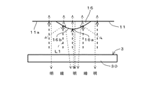
第1の照明装置3による第1照明光L1がびん底11の平坦面11aに当たると、その第1照明光L1が反射してかなりの量の光がカメラ5に向けて進むので、平坦面11aは明るく映る。なお、図中、明るく映る部分は「明」の文字で、暗く映る部分は「暗」の文字で、それぞれ示してある。また、第1の照明装置3からの第1照明光L1は太い点線で、びん底11での反射光や透過光は細い点線で、それぞれ示してある。 When the first illumination light L1 from the first illumination device 3 hits the flat surface 11a of the bottle bottom 11, the first illumination light L1 is reflected and a considerable amount of light travels toward the camera 5, so the flat surface 11a. Appears bright. In the drawing, a bright portion is indicated by “bright” characters, and a dark portion is indicated by “dark” characters. The first illumination light L1 from the first illumination device 3 is indicated by a thick dotted line, and the reflected light and transmitted light at the bottle bottom 11 are indicated by thin dotted lines.
第1の照明装置3による第1照明光L1が突起物16に当たると、突起物16の傾斜面16bに当たった第1照明光L1はカメラ5の方向へ反射せず、傾斜面16bは暗く映る。突起物16の頂部16aに当たった第1照明光L1は反射してかなりの量の光がカメラ5に向けて進むので、頂部16aは明るく映る。その結果、突起物16は傾斜面16bの暗く映った部分により縁取られたような画像、具体的には図9に示すような画像(以下、「第1画像」という。)G1となり、突起物16により表された情報の読み取りが容易である。
When the first illumination light L1 from the first illumination device 3 hits the
びん底11に泡Xが存在する場合、その泡Xの中空部分とびん10との境界はびん底11とほぼ平行でほぼ平坦な面を構成するので、第1の照明装置3による第1照明光L1が泡Xに当たると、泡Xの中空部分とびん10との境界において第1照明光L1が反射してかなりの量の光がカメラ5に向けて進み、泡Xの部分(図9において点線で示す。)は明るく映る。その結果、泡Xとびん底11の平坦面11aとは画像上で殆ど区別がつかない状態となる。
When the bubble X exists in the bottle bottom 11, the boundary between the hollow portion of the bubble X and the
図7および図8は、第2の照明装置4による第2照明光L2がびん底11の表面より盛り上がった突起物16およびびん底11の表面付近に存在する泡Xに照射された状態をそれぞれ示している。
第2の照明装置4による第2照明光L2がびん底11の平坦面11aに斜めに当たると、その第2照明光L2のかなりの量の光がカメラ5の方向以外の方向へ反射するので、平坦面11aは暗く映る。第2の照明装置4による第2照明光L2が突起物16に当たると、突起物16の傾斜面16bに当たった第2照明光L2はかなりの量の光がカメラ5に向けて反射するので、傾斜面16bは明るく映る。突起物16の頂部16aに当たった第2照明光L2はその一部がカメラ5に向けて反射するので、頂部16aは明るく映る。その結果、突起物16は傾斜面16bおよび頂部16aの明るく映った部分が白抜きとなるような画像、具体的には図10に示すような画像(以下、「第2画像」という。)G2となり、突起物16により表された情報の読み取りが可能である。
FIG. 7 and FIG. 8 show the state in which the second illumination light L2 from the
When the second illumination light L2 from the
びん底11に泡Xが存在する場合、その泡Xの中空部分とびんとの境界はびん底11とほぼ平行でほぼ平坦な面を構成するので、第2の照明装置4による第2照明光L2が泡Xに斜めに当たると、泡Xの中空部分とびん10との境界において第2照明光L2のかなりの量の光はカメラ5の方向以外の方向へ反射するが、びん底11と平行でない泡Xの周辺部分では泡Xの中空部分とびん10との境界において第2照明光L2のかなりの量の光がカメラ5に向けて反射するので、泡Xの周辺部分が明るく映る。その結果、図10に示す第2画像G2には、明るく映った泡Xの周辺部分による線状の画像LXが現れ、泡Xとびん底11の平坦面11aとは画像上で区別がつく状態となる。
When the bubble X exists in the bottle bottom 11, the boundary between the hollow portion of the bubble X and the bottle forms a substantially flat surface that is substantially parallel to the bottle bottom 11, so that the second illumination light from the
なお、この実施例では、検査対象のびん10のびん底11の下方に、びん底11に近い側より第2の照明装置4、第1の照明装置3の順に配置し、さらに第1の照明装置3より下方にカメラ5を配置することにより、第1照明光L1および第2照明光L2に対するびん底11からの反射光がカメラ5に入るようにしているが、これに限らず、カメラ5をびん10のびん口との対向位置に、びん口からびん底11を覗くようにして視野を定めて配置することによって、各照明装置3,4からびん底11を透過してカメラ5に入射する第1、第2の照明光L1,L2による画像を生成してもよい。この場合にも、第1の照明装置3による照明の下では、図9の第1画像G1と同様の画像を取得でき、第2の照明装置4による照明の下では、図10の第2画像G2と同様の画像を取得できる。
In this embodiment, the second illuminating
また、上記の実施例のような、びん底11に表された情報がびん底11の表面より盛り上がる突起物16によって表されたびんに限らず、びん底11の表面より傾斜して凹むような凹溝ないしは凹部、すなわち、断面がV字状の凹溝ないしは凹部によって表されたびんを検査する場合にも、第1の照明装置3による照明の下では図9の第1画像G1と同様の画像を取得でき、第2の照明装置4による照明の下では図10の第2画像G2と同様の画像を取得できる。
In addition, the information expressed in the bottle bottom 11 is not limited to the
図11は、図9,10に示した第1画像G1,第2画像G2をカメラ5より取り込んで処理する画像処理装置7の制御部の構成を、制御部が有する機能によって示した機能ブロック図である。
この実施例の画像処理装置7はコンピュータより成る制御部を有し、その制御部には、専用のプログラムによって、画像入力部71,前処理部72,文字認識処理部73,数字認識処理部74,コード認識処理部75,マスクデータ作成部76,マスク処理部77,欠陥検出部78,判定部79,判定結果出力部70などの各機能が設定されている。また制御部のメモリには、びん10の製造元を示す文字15の基準画像が登録された第1記憶部701、0〜9の各数字の基準画像が登録された第2記憶部702、型番のコードを読み取る処理に使用されるテンプレートが登録された第3記憶部703が設けられている。
FIG. 11 is a functional block diagram illustrating the configuration of the control unit of the
The
画像入力部71は、コントローラ6からの指令に応じて、第1の照明装置3や第2の照明装置4の点灯のタイミングに合わせてカメラ5から第1、第2の画像G1,G2を取り込む。前処理部72は、第1、第2の画像G1,G2のそれぞれに対し、動的しきい値法による2値化処理を実施した後、膨張処理および収縮処理を複数サイクル実施することによって、取り込んだ画像G1,G2を、ノイズが取り除かれかつ輪郭部分をスムージングした2値画像に変換する。
The
第1の照明装置3による照明の下で生成される第1画像G1が取り込まれると、前処理部72での処理によって第1画像G1が2値化された後に、文字認識処理部73,数字認識処理部74,コード認識処理部75が作動して、第1〜第3の各記憶部701〜703の登録データを用いて、2値画像に対し、製造元を表す文字15、型番を表す数字13、点列14が示すコードの読み取りが行われる。読み取りが正常に終了すると、マスクデータ作成部76は、読み取られた情報について2値画像から検出されてその読み取りのために処理された突起物16の画像を用いてマスクデータを作成する。
なお、後記するように、文字認識処理部73の認識処理において第1画像G1の文字15の画像の幅方向が画像の水平方向に対して傾いていることが検出された場合には、前処理部72によって、文字15の画像の幅方向が画像の水平方向に沿う状態になるように2値画像の回転補正が実施され、その補正後の2値画像に対して数字認識処理部74による数字の認識処理やコード認識処理部75によるコードの認識処理が実施される。
When the first image G1 generated under illumination by the first lighting device 3 is captured, the first image G1 is binarized by the processing in the
As will be described later, when it is detected in the recognition processing of the character
第2の照明装置4による照明の下で生成される第2画像G2が取り込まれると、前処理部72での処理の後に、まずマスク処理部77が作動して、第2画像G2から変換された2値画像にマスクデータ作成部76により作成されたマスクデータに基づくマスク領域を設定し、その後に、欠陥検出部78によって欠陥の検出処理が実施され、さらに判定部79によって欠陥の有無が判定される。判定結果出力部70は、個々のびん10毎の検査結果を各認識処理部73,74,75により認識された情報と組にして出力する。なお、第1画像G1の2値画像に対して回転補正が行われた場合には、第2画像G2の2値画像に対しても同様の補正が実施される。
When the second image G2 generated under illumination by the second illuminating
図12は、図9に示した第1画像G1および図10に示した第2画像G2を例として、第1画像G1に対する読取結果に基づきマスクデータを作成し、そのマスクデータを用いて第2画像G2から泡を検出する処理の概要を示している。 FIG. 12 shows an example of the first image G1 shown in FIG. 9 and the second image G2 shown in FIG. 10, and creates mask data based on the read result of the first image G1, and uses the mask data to generate the second data. The outline | summary of the process which detects a bubble from the image G2 is shown.
図12(A)は図9に示したのと同様の第1画像G1を示し、図12(B)は第1画像G1に対する前処理部72の処理により生成された2値画像G1´を示す。図5および図6により説明した第1照明光L1の作用により生成された第1画像G1は、前処理部72の処理によって、各突起物16の傾斜面16bの暗く映った部分に相当する黒画素が途切れずにある程度の幅をもってスムーズに連なった2値画像G1´に変換される。つまり、2値画像G1´では、個々の突起物16がそれぞれその輪郭に沿う線状の黒画素領域により表されるようになる。一方、第1画像G1中の泡Xのかすかな映り込み部分は2値画像G1´では白画素領域に変換される。この2値画像G1´に対して文字認識処理部73,数字認識処理部74,コード認識処理部75による認識処理が実施された後、マスクデータ作成部76によって図12(C)に示すようなマスクデータが作成される。
FIG. 12A shows a first image G1 similar to that shown in FIG. 9, and FIG. 12B shows a binary image G1 ′ generated by the processing of the
図12(D)は図10に示したのと同様の第2画像G2を示し、図12(E)は第2画像G2から生成された2値画像G2´を示す。図7および図8により説明した第2照明光L2の作用により生成された第2画像G2は、前処理部72の処理によって、びん底11の平坦面が黒画素領域となり、泡Xの周辺部分を表す明るい線状の画像LXと各突起物16の傾斜面16bや頂部16aが明るく映った部分とが白画素領域となる2値画像G2´に変換される。この2値画像G2´に対してマスク処理部77が図12(C)のマスクデータを用いてマスク領域を設定することにより、図12(F)に示すように、2値画像G2´中の各突起物16が映った部分は処理対象から除外される。
FIG. 12D shows a second image G2 similar to that shown in FIG. 10, and FIG. 12E shows a binary image G2 ′ generated from the second image G2. In the second image G2 generated by the action of the second illumination light L2 described with reference to FIGS. 7 and 8, the flat surface of the bottle bottom 11 becomes a black pixel region by the processing of the
図13は、画像処理装置7およびコントローラ6により実施される型番の読み取りから泡Xの検出処理に至る処理の手順を示している。これらの手順(図中、各手順を「ST」で示す。)は、びん10が検査位置に導入されるタイミングに合わせて順次、そして繰り返し実行される。以下、先の図12のほか、図14,図15を参照しつつ、図13中の各手順を説明する。
FIG. 13 shows a processing procedure from reading of a model number to detection processing of the bubble X performed by the
検査対象のびん10が図1に示した最終の検査ステーションTの検査位置に導入されると、図13のST1の判定が「YES」となり、コントローラ6は第1の照明装置3を点灯させ、びん10のびん底11へ第1の照明装置3による第1照明光L1が照射される(ST2)。つぎのST3では、この第1の照明装置3の点灯状態下でカメラ5によりびん底11が撮像され、カメラ5で取得された第1画像G1(図12(A)を参照)が画像処理装置7の画像入力部71により取り込まれ、図示しない画像メモリに格納される。
When the
第1画像G1の取込みが終了すると、前処理部72による2値化処理(ST4)、膨張処理および収縮処理(ST5)が順次実施され、第1画像G1は図12(B)に示すような2値画像G1´に変換される。
When the capture of the first image G1 is finished, the binarization process (ST4), the expansion process and the contraction process (ST5) by the
文字認識処理部73は、第1記憶部701の文字基準画像を用いて上記の2値画像G1´に対するパターンマッチング処理を実施することにより、製造元を表す文字15の画像を含む領域R1(図14参照)を検出する(ST6)。この処理によって、文字基準画像に対する領域R1の傾きを表す角度(前述した画像の水平方向に対する文字15の幅方向の傾きに相当する。)が検出されるので、次のST7では、その角度に基づき、前処理部72によって傾きを解消するための画像の回転補正が行われる。この補正に使用された角度は、後記する第2画像G2に対する処理のために一時保存される。
The character
回転補正の後は、数値認識処理部74による認識処理(ST8)が実施され、ついでコード認識処理部75による認識処理(ST9)が実施される。
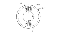
まずST8において、数値認識処理部74は、図14に示すように、基準領域R1を含むようなドーナツ状の基準検索領域Sを設定して、この基準検索領域S内であって基準検索領域Sの内側の円形領域を挟んで領域R1と向かい合う位置に読取領域R2を設定する。さらに数字認識処理部74は、第2記憶部702に登録されている各種数字の基準画像を用いて読取領域R2に含まれる個々の数字を認識する。
After the rotation correction, recognition processing (ST8) by the numerical value
First, in ST8, the numerical value
ST9において、コード認識処理部75は、基準検索領域Sの内側の円形の画像領域を第3記憶部703に登録されているテンプレートを用いて照合する。この実施例の点列14は、型番を表す8ビットのコードに目印の符号を組み合わせた構成のものであり、第3記憶部703には、目印の符号を含むコード全体の各桁に対応する領域の配置のパターン(各領域の大きさおよび位置関係を示すもの)やそのパターン中の目印の符号に対応する領域における突起物16の有無を表すテンプレートが登録されている。コード認識処理部75は、テンプレートの位置や回転角度を種々に変更して2値画像G1´の基準検索領域Sの内側の領域とテンプレートとを照合することにより、基準検索領域S内で目印の符号を表す領域を検出する。さらに、検出された領域を目印の符号に対応する領域に位置合わせした状態のテンプレートと2値画像G1´とを照合して、型番を表す8ビットのコードの各桁に対応する領域に突起物16の輪郭を表す黒画素領域が存在するか否かを判別し、その判別結果から型番を表すコードを認識する。
In ST9, the code recognition processing unit 75 collates the circular image region inside the reference search region S using the template registered in the
ST8およびST9で型番が適正に読み取られると、ST10の判定が「YES」となって、ST11に進み、マスクデータ作成部76は、ST6,ST8,ST9の各認識処理で読み取られた情報の読み取りに使用された線状の黒画素領域を用いてマスクデータを作成する。
If the model number is properly read in ST8 and ST9, the determination in ST10 is “YES”, and the process proceeds to ST11. The mask
図15は、図12(B)の2値画像G1´に現れている線状の黒画素領域のうち、文字「S」を表す突起物16の輪郭を表す黒画素領域を用いてマスクデータを作成する例を示す。この図15を参照してST11の処理を説明すると、マスクデータ作成部76は、2値画像G1´において「S」という文字を表すと認識された黒画素領域、言い換えると読み取られた文字情報「S」を表す突起物16の輪郭を表す線状の黒画素領域(図15(a)を参照)を幅方向に所定画素数分膨張させる。具体的には、図15(b)に示すように、両隣の白画素領域に対する境界位置をそれぞれ所定画素数分だけ白画素領域の側に移動させる(図15(b)では、わかりやすくするために、膨張された黒画素領域を網点パターンで示している。)。さらに、マスクデータ作成部76は、膨張後の黒画素領域により囲まれる画像領域の全体をマスク対象とするマスクデータ(図15(c))を設定する。具体的なマスクデータは、たとえば、膨張後の黒画素領域およびこの黒画素領域により囲まれる白画素領域内の全ての画素に値「1」が設定され、その他の画素に値「0」が設定された2値データとなる。
FIG. 15 shows the mask data using the black pixel region representing the outline of the
図13に参照を戻す。マスクデータが作成されると、つぎに、コントローラ6は、第1の照明装置3を消灯させかつ第2の照明装置4を点灯させ、びん10のびん底11へ第2照明光L2が照射される(ST12)。つぎのST13では、この第2照明光L2による照明下でカメラ5によりびん底11が撮像され、カメラ5で取得された第2画像G2(図12(D)参照)が画像入力部71により画像処理装置7に取り込まれ、図示しない画像メモリに格納される。
Returning to FIG. When the mask data is created, the controller 6 then turns off the first lighting device 3 and turns on the
前処理部72は、この第2画像G2に対して、ST14で2値化処理を実施し、続くST15で膨張処理および収縮処理を実施して、第2画像G2を図12(E)に示すような2値画像G2´に変換する(ST14,ST15)。つぎのST16では、前処理部72は、ST7の補正処理で使用した角度を用いて第2画像G2の2値画像G2´の回転補正を実施する。
The
つぎに、マスク処理部77は、ST11で作成されたマスクデータに基づくマスク領域を第2画像G2の2値画像G2´に設定する(ST17)。このマスク領域の設定によって、2値画像G2´は、図12(F)に示すように、突起物16を表す白画素領域がマスクされた状態になる。
Next, the
欠陥検出部78は、上記のマスク領域を除く画像領域に含まれる白画素を計測することにより泡Xの検出処理を実行し(ST18)、判定部79はその計測値を用いて泡の有無を判定する(ST19)。具体的には、判定部79は、白画素の計測値をあらかじめ登録されたしきい値と照合し、しきい値を越える画素が所定数以上連続する場合に泡が存在すると判定する。
The
なお、泡が存在すると判定された場合(ST20が「YES」)や型番の読み取りに失敗した場合(ST10が「NO」)には、図示しない異常処理に移行する。 When it is determined that bubbles are present (ST20 is “YES”) or when reading of the model number is unsuccessful (ST10 is “NO”), the process proceeds to an abnormal process (not shown).
第1画像G1と第2画像G2とは同一のびん10のびん底11を撮像して得られたものであるが、それぞれの撮像時の照明条件の違いによって、第2画像G2の突起物16が映った部分が第1画像G1の突起物16が映った部分からずれ、そのずれを反映して、第2画像G2の2値画像G2´において突起物16を表す白画素領域も第1画像G1の2値画像G1´において突起物16の輪郭を表す黒画素領域からずれる可能性がある。図15を用いて説明したように、この実施例では、第1画像G1の2値画像G1´から読み取られた情報を表す黒画素領域を幅方向に膨張させ、膨張後の黒画素領域により表される画像領域全体をマスク領域とするマスクデータを作成するので、2値画像G2´中の突起物16を表す白画素領域が2値画像G1´中の突起物を表す黒画素領域から若干ずれた場合でも、そのずれ部分を含む突起物16の画像全体をマスク領域内に含めることができる。よって、ST18の泡の検出処理で突起物16を示す白画素が計測されることがなく、泡の周辺部分を表す白画素のみが計測されるので、ST19でも泡の有無を正しく判定することができる。
The first image G1 and the second image G2 are obtained by imaging the
上記の実施例では、第1画像G1の2値画像G1´に対しては突起物16が示す情報を読み取る処理のみが実施されるものとして説明したが、その読取処理後にマスク処理部77,欠陥検出部78を作動させることにより、第1画像G1の2値画像G1´に対してもマスクデータ作成部76が作成したマスクデータに基づくマスク領域を設定して欠陥の検出処理を行ってもよい。この場合、判定部79は、第1画像G1の2値画像G1´に対する欠陥の検出結果と第2画像G2の2値画像G2´に対する欠陥の検出結果とを統合して、欠陥の有無を判定する。
なお、第2画像G2の2値画像G2´に対する処理で検出される欠陥も泡に限らず、ガラスの溶融異常箇所などを検出することもできる。
In the above-described embodiment, it has been described that only the process of reading the information indicated by the
In addition, the defect detected by the process with respect to the 2nd image G2 'of the 2nd image G2 is not restricted to a bubble, The melting | fusing abnormal location etc. of glass can also be detected.
1 びん底検査装置
2 位置決め機構
3 第1の照明装置
4 第2の照明装置
5 カメラ
6 コントローラ
7 画像処理装置
10 びん
11 びん底
73 文字認識処理部
74 数字認識処理部
75 コード認識処理部
76 マスクデータ作成部
77 マスク処理部
78 欠陥検出部
79 判定部
L1 照明光
L2 照明光
X 泡
LX 泡の輪郭線
DESCRIPTION OF
Claims (2)
Priority Applications (1)
| Application Number | Priority Date | Filing Date | Title |
|---|---|---|---|
| JP2014068668A JP6049652B2 (en) | 2014-03-28 | 2014-03-28 | Bottle bottom inspection device |
Applications Claiming Priority (1)
| Application Number | Priority Date | Filing Date | Title |
|---|---|---|---|
| JP2014068668A JP6049652B2 (en) | 2014-03-28 | 2014-03-28 | Bottle bottom inspection device |
Publications (2)
| Publication Number | Publication Date |
|---|---|
| JP2015190872A true JP2015190872A (en) | 2015-11-02 |
| JP6049652B2 JP6049652B2 (en) | 2016-12-21 |
Family
ID=54425467
Family Applications (1)
| Application Number | Title | Priority Date | Filing Date |
|---|---|---|---|
| JP2014068668A Active JP6049652B2 (en) | 2014-03-28 | 2014-03-28 | Bottle bottom inspection device |
Country Status (1)
| Country | Link |
|---|---|
| JP (1) | JP6049652B2 (en) |
Cited By (3)
| Publication number | Priority date | Publication date | Assignee | Title |
|---|---|---|---|---|
| CN111426697A (en) * | 2020-05-09 | 2020-07-17 | 北京妙想科技有限公司 | Body defect visual inspection device |
| WO2023089954A1 (en) * | 2021-11-22 | 2023-05-25 | 東洋ガラス株式会社 | Glass bottle bottom inspection device |
| CN116935080A (en) * | 2023-09-19 | 2023-10-24 | 深圳市瑞意博医疗设备有限公司 | Injection medicine identification method, system and storage cabinet |
Citations (4)
| Publication number | Priority date | Publication date | Assignee | Title |
|---|---|---|---|---|
| JPS5712352A (en) * | 1980-06-26 | 1982-01-22 | Hajime Sangyo Kk | Light diffusion device |
| JPH0634573A (en) * | 1992-07-20 | 1994-02-08 | Asahi Chem Ind Co Ltd | Bottle inspector |
| JP2002122550A (en) * | 2000-08-11 | 2002-04-26 | Ajinomoto Faruma Kk | Device and method for inspection of foreign matter in flexible plastic container |
| JP2012242148A (en) * | 2011-05-17 | 2012-12-10 | Kurabo Ind Ltd | Appearance inspection apparatus and appearance inspection method of transparent bottle |
-
2014
- 2014-03-28 JP JP2014068668A patent/JP6049652B2/en active Active
Patent Citations (4)
| Publication number | Priority date | Publication date | Assignee | Title |
|---|---|---|---|---|
| JPS5712352A (en) * | 1980-06-26 | 1982-01-22 | Hajime Sangyo Kk | Light diffusion device |
| JPH0634573A (en) * | 1992-07-20 | 1994-02-08 | Asahi Chem Ind Co Ltd | Bottle inspector |
| JP2002122550A (en) * | 2000-08-11 | 2002-04-26 | Ajinomoto Faruma Kk | Device and method for inspection of foreign matter in flexible plastic container |
| JP2012242148A (en) * | 2011-05-17 | 2012-12-10 | Kurabo Ind Ltd | Appearance inspection apparatus and appearance inspection method of transparent bottle |
Cited By (4)
| Publication number | Priority date | Publication date | Assignee | Title |
|---|---|---|---|---|
| CN111426697A (en) * | 2020-05-09 | 2020-07-17 | 北京妙想科技有限公司 | Body defect visual inspection device |
| WO2023089954A1 (en) * | 2021-11-22 | 2023-05-25 | 東洋ガラス株式会社 | Glass bottle bottom inspection device |
| CN116935080A (en) * | 2023-09-19 | 2023-10-24 | 深圳市瑞意博医疗设备有限公司 | Injection medicine identification method, system and storage cabinet |
| CN116935080B (en) * | 2023-09-19 | 2024-01-05 | 深圳市瑞意博医疗设备有限公司 | Injection medicine identification method, system and storage cabinet |
Also Published As
| Publication number | Publication date |
|---|---|
| JP6049652B2 (en) | 2016-12-21 |
Similar Documents
| Publication | Publication Date | Title |
|---|---|---|
| WO2015098929A1 (en) | Surface defect detection method and surface defect detection device | |
| US20060000968A1 (en) | Glass bottle inspection device | |
| JPS62184908A (en) | Automatic discriminating method of tire | |
| JP6134383B2 (en) | Optical method for inspecting transparent or translucent containers with visible patterns | |
| KR102613277B1 (en) | Surface-defect detecting method, surface-defect detecting apparatus, steel-material manufacturing method, steel-material quality management method, steel-material manufacturing facility, surface-defect determination model generating method, and surface-defect determination model | |
| JP7382519B2 (en) | Glass bottle inspection method, glass bottle manufacturing method, and glass bottle inspection device | |
| CN107709977B (en) | Surface defect detection device and surface defect detection method | |
| JP6049652B2 (en) | Bottle bottom inspection device | |
| KR102300158B1 (en) | Container inspection device and container inspection method | |
| JP4986255B1 (en) | Container mouth inspection method and apparatus | |
| JP2007316019A (en) | Surface defect inspection device | |
| JP7063839B2 (en) | Inspection method and inspection system | |
| JP6073261B2 (en) | Bottle bottom inspection device | |
| JP4886830B2 (en) | Burn glass inspection method and apparatus for transparent glass container | |
| JP2008216180A (en) | Surface state inspection method and surface state inspection device | |
| JP4444273B2 (en) | Transparency or translucent article embossed character reading method and apparatus | |
| TWI753384B (en) | Glass bottle inspection method and glass bottle manufacturing method | |
| JP7040972B2 (en) | Support ring inspection device and support ring inspection method for containers with support rings | |
| JP6670428B2 (en) | Preform inspection method and inspection device | |
| JP2007333661A (en) | Method and apparatus for visual inspection of electronic component | |
| JP2013257245A (en) | Inspection device for articles | |
| JP2012150072A (en) | Checkup of inscription on mouth of transparent container | |
| JP4315899B2 (en) | Surface inspection method and surface inspection apparatus | |
| JP6688629B2 (en) | Defect detecting device, defect detecting method and program | |
| JPS6232345A (en) | Defect detecting device |
Legal Events
| Date | Code | Title | Description |
|---|---|---|---|
| A977 | Report on retrieval |
Free format text: JAPANESE INTERMEDIATE CODE: A971007 Effective date: 20160329 |
|
| A131 | Notification of reasons for refusal |
Free format text: JAPANESE INTERMEDIATE CODE: A131 Effective date: 20160405 |
|
| A521 | Request for written amendment filed |
Free format text: JAPANESE INTERMEDIATE CODE: A523 Effective date: 20160524 |
|
| RD02 | Notification of acceptance of power of attorney |
Free format text: JAPANESE INTERMEDIATE CODE: A7422 Effective date: 20160607 |
|
| TRDD | Decision of grant or rejection written | ||
| A01 | Written decision to grant a patent or to grant a registration (utility model) |
Free format text: JAPANESE INTERMEDIATE CODE: A01 Effective date: 20161101 |
|
| A61 | First payment of annual fees (during grant procedure) |
Free format text: JAPANESE INTERMEDIATE CODE: A61 Effective date: 20161122 |
|
| R150 | Certificate of patent or registration of utility model |
Ref document number: 6049652 Country of ref document: JP Free format text: JAPANESE INTERMEDIATE CODE: R150 |
|
| R250 | Receipt of annual fees |
Free format text: JAPANESE INTERMEDIATE CODE: R250 |
|
| R250 | Receipt of annual fees |
Free format text: JAPANESE INTERMEDIATE CODE: R250 |
|
| R250 | Receipt of annual fees |
Free format text: JAPANESE INTERMEDIATE CODE: R250 |
|
| R250 | Receipt of annual fees |
Free format text: JAPANESE INTERMEDIATE CODE: R250 |
|
| R250 | Receipt of annual fees |
Free format text: JAPANESE INTERMEDIATE CODE: R250 |