JP2015179933A - Vibration element, gyro sensor element, electronic device, electronic apparatus and moving body - Google Patents
Vibration element, gyro sensor element, electronic device, electronic apparatus and moving body Download PDFInfo
- Publication number
- JP2015179933A JP2015179933A JP2014056091A JP2014056091A JP2015179933A JP 2015179933 A JP2015179933 A JP 2015179933A JP 2014056091 A JP2014056091 A JP 2014056091A JP 2014056091 A JP2014056091 A JP 2014056091A JP 2015179933 A JP2015179933 A JP 2015179933A
- Authority
- JP
- Japan
- Prior art keywords
- vibration element
- gyro sensor
- vibration
- arm
- drive arm
- Prior art date
- Legal status (The legal status is an assumption and is not a legal conclusion. Google has not performed a legal analysis and makes no representation as to the accuracy of the status listed.)
- Withdrawn
Links
- 238000001514 detection method Methods 0.000 claims description 68
- 230000007423 decrease Effects 0.000 claims description 8
- 238000004519 manufacturing process Methods 0.000 abstract description 16
- 239000013078 crystal Substances 0.000 description 13
- 230000000694 effects Effects 0.000 description 8
- 239000000758 substrate Substances 0.000 description 7
- 238000005452 bending Methods 0.000 description 6
- 239000010931 gold Substances 0.000 description 6
- 238000003384 imaging method Methods 0.000 description 5
- 239000000463 material Substances 0.000 description 5
- 238000000034 method Methods 0.000 description 5
- 239000010949 copper Substances 0.000 description 4
- 238000005530 etching Methods 0.000 description 4
- 230000006870 function Effects 0.000 description 4
- 230000035945 sensitivity Effects 0.000 description 4
- 239000000853 adhesive Substances 0.000 description 3
- 230000001070 adhesive effect Effects 0.000 description 3
- 230000001413 cellular effect Effects 0.000 description 3
- 239000000919 ceramic Substances 0.000 description 3
- 238000004891 communication Methods 0.000 description 3
- PCHJSUWPFVWCPO-UHFFFAOYSA-N gold Chemical compound [Au] PCHJSUWPFVWCPO-UHFFFAOYSA-N 0.000 description 3
- 229910052737 gold Inorganic materials 0.000 description 3
- 230000003287 optical effect Effects 0.000 description 3
- BASFCYQUMIYNBI-UHFFFAOYSA-N platinum Chemical compound [Pt] BASFCYQUMIYNBI-UHFFFAOYSA-N 0.000 description 3
- 239000010453 quartz Substances 0.000 description 3
- 238000007789 sealing Methods 0.000 description 3
- VYPSYNLAJGMNEJ-UHFFFAOYSA-N silicon dioxide Inorganic materials O=[Si]=O VYPSYNLAJGMNEJ-UHFFFAOYSA-N 0.000 description 3
- IJGRMHOSHXDMSA-UHFFFAOYSA-N Atomic nitrogen Chemical compound N#N IJGRMHOSHXDMSA-UHFFFAOYSA-N 0.000 description 2
- RYGMFSIKBFXOCR-UHFFFAOYSA-N Copper Chemical compound [Cu] RYGMFSIKBFXOCR-UHFFFAOYSA-N 0.000 description 2
- 239000011651 chromium Substances 0.000 description 2
- 229910052802 copper Inorganic materials 0.000 description 2
- 230000003247 decreasing effect Effects 0.000 description 2
- 238000001312 dry etching Methods 0.000 description 2
- 230000005284 excitation Effects 0.000 description 2
- 239000010955 niobium Substances 0.000 description 2
- 229910052709 silver Inorganic materials 0.000 description 2
- 239000004332 silver Substances 0.000 description 2
- 239000010936 titanium Substances 0.000 description 2
- WSMQKESQZFQMFW-UHFFFAOYSA-N 5-methyl-pyrazole-3-carboxylic acid Chemical compound CC1=CC(C(O)=O)=NN1 WSMQKESQZFQMFW-UHFFFAOYSA-N 0.000 description 1
- 241000251468 Actinopterygii Species 0.000 description 1
- 229910001316 Ag alloy Inorganic materials 0.000 description 1
- 229910000838 Al alloy Inorganic materials 0.000 description 1
- 229910001020 Au alloy Inorganic materials 0.000 description 1
- VYZAMTAEIAYCRO-UHFFFAOYSA-N Chromium Chemical compound [Cr] VYZAMTAEIAYCRO-UHFFFAOYSA-N 0.000 description 1
- 229910000599 Cr alloy Inorganic materials 0.000 description 1
- YCKRFDGAMUMZLT-UHFFFAOYSA-N Fluorine atom Chemical compound [F] YCKRFDGAMUMZLT-UHFFFAOYSA-N 0.000 description 1
- WQZGKKKJIJFFOK-GASJEMHNSA-N Glucose Natural products OC[C@H]1OC(O)[C@H](O)[C@@H](O)[C@@H]1O WQZGKKKJIJFFOK-GASJEMHNSA-N 0.000 description 1
- XEEYBQQBJWHFJM-UHFFFAOYSA-N Iron Chemical compound [Fe] XEEYBQQBJWHFJM-UHFFFAOYSA-N 0.000 description 1
- ZOKXTWBITQBERF-UHFFFAOYSA-N Molybdenum Chemical compound [Mo] ZOKXTWBITQBERF-UHFFFAOYSA-N 0.000 description 1
- 239000004642 Polyimide Substances 0.000 description 1
- XUIMIQQOPSSXEZ-UHFFFAOYSA-N Silicon Chemical compound [Si] XUIMIQQOPSSXEZ-UHFFFAOYSA-N 0.000 description 1
- BQCADISMDOOEFD-UHFFFAOYSA-N Silver Chemical compound [Ag] BQCADISMDOOEFD-UHFFFAOYSA-N 0.000 description 1
- RTAQQCXQSZGOHL-UHFFFAOYSA-N Titanium Chemical compound [Ti] RTAQQCXQSZGOHL-UHFFFAOYSA-N 0.000 description 1
- QCWXUUIWCKQGHC-UHFFFAOYSA-N Zirconium Chemical compound [Zr] QCWXUUIWCKQGHC-UHFFFAOYSA-N 0.000 description 1
- 229910052782 aluminium Inorganic materials 0.000 description 1
- XAGFODPZIPBFFR-UHFFFAOYSA-N aluminium Chemical compound [Al] XAGFODPZIPBFFR-UHFFFAOYSA-N 0.000 description 1
- 239000008280 blood Substances 0.000 description 1
- 210000004369 blood Anatomy 0.000 description 1
- 230000036772 blood pressure Effects 0.000 description 1
- 229910052804 chromium Inorganic materials 0.000 description 1
- 239000000788 chromium alloy Substances 0.000 description 1
- 239000010941 cobalt Substances 0.000 description 1
- 229910017052 cobalt Inorganic materials 0.000 description 1
- GUTLYIVDDKVIGB-UHFFFAOYSA-N cobalt atom Chemical compound [Co] GUTLYIVDDKVIGB-UHFFFAOYSA-N 0.000 description 1
- 239000004020 conductor Substances 0.000 description 1
- 239000013013 elastic material Substances 0.000 description 1
- 230000005684 electric field Effects 0.000 description 1
- 239000011737 fluorine Substances 0.000 description 1
- 229910052731 fluorine Inorganic materials 0.000 description 1
- 239000011888 foil Substances 0.000 description 1
- 239000007789 gas Substances 0.000 description 1
- 239000008103 glucose Substances 0.000 description 1
- 239000003353 gold alloy Substances 0.000 description 1
- AMGQUBHHOARCQH-UHFFFAOYSA-N indium;oxotin Chemical compound [In].[Sn]=O AMGQUBHHOARCQH-UHFFFAOYSA-N 0.000 description 1
- 239000011261 inert gas Substances 0.000 description 1
- HFGPZNIAWCZYJU-UHFFFAOYSA-N lead zirconate titanate Chemical compound [O-2].[O-2].[O-2].[O-2].[O-2].[Ti+4].[Zr+4].[Pb+2] HFGPZNIAWCZYJU-UHFFFAOYSA-N 0.000 description 1
- 229910052451 lead zirconate titanate Inorganic materials 0.000 description 1
- GQYHUHYESMUTHG-UHFFFAOYSA-N lithium niobate Chemical compound [Li+].[O-][Nb](=O)=O GQYHUHYESMUTHG-UHFFFAOYSA-N 0.000 description 1
- 230000033001 locomotion Effects 0.000 description 1
- 229910052751 metal Inorganic materials 0.000 description 1
- 239000002184 metal Substances 0.000 description 1
- 239000007769 metal material Substances 0.000 description 1
- 229910052750 molybdenum Inorganic materials 0.000 description 1
- 239000011733 molybdenum Substances 0.000 description 1
- 238000012544 monitoring process Methods 0.000 description 1
- 229910052758 niobium Inorganic materials 0.000 description 1
- GUCVJGMIXFAOAE-UHFFFAOYSA-N niobium atom Chemical compound [Nb] GUCVJGMIXFAOAE-UHFFFAOYSA-N 0.000 description 1
- 229910052757 nitrogen Inorganic materials 0.000 description 1
- 238000000206 photolithography Methods 0.000 description 1
- 229910052697 platinum Inorganic materials 0.000 description 1
- 229920001721 polyimide Polymers 0.000 description 1
- 229920001296 polysiloxane Polymers 0.000 description 1
- 230000002265 prevention Effects 0.000 description 1
- 230000003014 reinforcing effect Effects 0.000 description 1
- 239000011347 resin Substances 0.000 description 1
- 229920005989 resin Polymers 0.000 description 1
- 239000004065 semiconductor Substances 0.000 description 1
- 229910052710 silicon Inorganic materials 0.000 description 1
- 239000010703 silicon Substances 0.000 description 1
- -1 silver halide Chemical class 0.000 description 1
- JBQYATWDVHIOAR-UHFFFAOYSA-N tellanylidenegermanium Chemical compound [Te]=[Ge] JBQYATWDVHIOAR-UHFFFAOYSA-N 0.000 description 1
- 229910052719 titanium Inorganic materials 0.000 description 1
- WFKWXMTUELFFGS-UHFFFAOYSA-N tungsten Chemical compound [W] WFKWXMTUELFFGS-UHFFFAOYSA-N 0.000 description 1
- 229910052721 tungsten Inorganic materials 0.000 description 1
- 239000010937 tungsten Substances 0.000 description 1
- 229910052726 zirconium Inorganic materials 0.000 description 1
Images


Classifications
-
- G—PHYSICS
- G01—MEASURING; TESTING
- G01C—MEASURING DISTANCES, LEVELS OR BEARINGS; SURVEYING; NAVIGATION; GYROSCOPIC INSTRUMENTS; PHOTOGRAMMETRY OR VIDEOGRAMMETRY
- G01C19/00—Gyroscopes; Turn-sensitive devices using vibrating masses; Turn-sensitive devices without moving masses; Measuring angular rate using gyroscopic effects
- G01C19/56—Turn-sensitive devices using vibrating masses, e.g. vibratory angular rate sensors based on Coriolis forces
- G01C19/5607—Turn-sensitive devices using vibrating masses, e.g. vibratory angular rate sensors based on Coriolis forces using vibrating tuning forks
- G01C19/5621—Turn-sensitive devices using vibrating masses, e.g. vibratory angular rate sensors based on Coriolis forces using vibrating tuning forks the devices involving a micromechanical structure
-
- H—ELECTRICITY
- H03—ELECTRONIC CIRCUITRY
- H03H—IMPEDANCE NETWORKS, e.g. RESONANT CIRCUITS; RESONATORS
- H03H9/00—Networks comprising electromechanical or electro-acoustic devices; Electromechanical resonators
- H03H9/15—Constructional features of resonators consisting of piezoelectric or electrostrictive material
- H03H9/21—Crystal tuning forks
-
- H—ELECTRICITY
- H03—ELECTRONIC CIRCUITRY
- H03H—IMPEDANCE NETWORKS, e.g. RESONANT CIRCUITS; RESONATORS
- H03H9/00—Networks comprising electromechanical or electro-acoustic devices; Electromechanical resonators
- H03H9/02—Details
- H03H9/05—Holders; Supports
- H03H9/0538—Constructional combinations of supports or holders with electromechanical or other electronic elements
- H03H9/0547—Constructional combinations of supports or holders with electromechanical or other electronic elements consisting of a vertical arrangement
-
- H—ELECTRICITY
- H03—ELECTRONIC CIRCUITRY
- H03H—IMPEDANCE NETWORKS, e.g. RESONANT CIRCUITS; RESONATORS
- H03H9/00—Networks comprising electromechanical or electro-acoustic devices; Electromechanical resonators
- H03H9/02—Details
- H03H9/05—Holders; Supports
- H03H9/10—Mounting in enclosures
- H03H9/1007—Mounting in enclosures for bulk acoustic wave [BAW] devices
- H03H9/1014—Mounting in enclosures for bulk acoustic wave [BAW] devices the enclosure being defined by a frame built on a substrate and a cap, the frame having no mechanical contact with the BAW device
Landscapes
- Physics & Mathematics (AREA)
- Engineering & Computer Science (AREA)
- General Physics & Mathematics (AREA)
- Radar, Positioning & Navigation (AREA)
- Remote Sensing (AREA)
- Acoustics & Sound (AREA)
- Chemical & Material Sciences (AREA)
- Crystallography & Structural Chemistry (AREA)
- Gyroscopes (AREA)
- Piezo-Electric Or Mechanical Vibrators, Or Delay Or Filter Circuits (AREA)
Abstract
Description
本発明は、振動素子、ジャイロセンサー素子、電子デバイス、電子機器および移動体に関する。 The present invention relates to a vibration element, a gyro sensor element, an electronic device, an electronic apparatus, and a moving body.
従来から、振動素子やジャイロセンサー素子は、携帯電話やデジタルカメラなどの電子機器、および自動車などの移動体に使用されている。これらの電子機器や移動体の高性能化の要求に伴い、振動素子やジャイロセンサー素子にも、低インピーダンス化や検出感度の向上が求められている。例えば、特許文献1には、駆動腕部に貫通溝と貫通溝を補強する剛性補強部とが設けられた構成の振動片が示されている。また、特許文献2には、励振用駆動腕部に貫通穴が複数個配列された構成の慣性センサーが示されている。これらの構成により駆動腕の剛性が高められ、駆動腕の側面と、この側面に対向する貫通溝または貫通穴の側面と、に励振用電極を形成することでインピーダンス(CI値、直列等価抵抗)を下げることが可能な振動片および慣性センサーが知られていた。
Conventionally, vibration elements and gyro sensor elements are used in electronic devices such as mobile phones and digital cameras, and mobile objects such as automobiles. Along with the demand for higher performance of these electronic devices and moving objects, vibration elements and gyro sensor elements are also required to have low impedance and improved detection sensitivity. For example,
しかしながら、近年、振動素子やジャイロセンサー素子の小型化が進み、駆動腕の幅も著しく狭くなっている。素子のインピーダンスを下げるために設けられる貫通孔も狭くなり、開口面積の狭い貫通孔を設けることが困難であるという課題があった。逆に、駆動腕の幅寸法を広げて貫通孔を大きくすることが考えられる。しかし、駆動腕の幅をW、駆動腕の長さをLとした場合、駆動腕の振動周波数fは、
f∝W/L2・・・・・式1
の関係を満たさなければならない。このため、駆動腕の幅を広くすればするほど、駆動腕の長さも長くしなければならず、駆動腕の外形寸法が大きくなるという課題があった。すなわち、小型でインピーダンスの低い振動素子、ジャイロセンサー素子を提供することが困難であった。
However, in recent years, the vibration element and the gyro sensor element have been miniaturized, and the width of the driving arm has been remarkably reduced. The through hole provided for lowering the impedance of the element is also narrowed, and there is a problem that it is difficult to provide a through hole with a small opening area. Conversely, it is conceivable to increase the width of the drive arm to enlarge the through hole. However, when the width of the drive arm is W and the length of the drive arm is L, the vibration frequency f of the drive arm is
f∝W /
Must satisfy the relationship. For this reason, the wider the width of the drive arm, the longer the length of the drive arm, and the larger the outer dimensions of the drive arm. That is, it has been difficult to provide a small vibration element and a gyro sensor element with low impedance.
本発明は、上述の課題の少なくとも一部を解決するためになされたものであり、以下の形態または適用例として実現することが可能である。 SUMMARY An advantage of some aspects of the invention is to solve at least a part of the problems described above, and the invention can be implemented as the following forms or application examples.
[適用例1]本適用例に係る振動素子は、基部と、前記基部から延出され、貫通孔が設けられている駆動腕と、を備え、前記駆動腕は、面内方向に沿って振動し、前記面内方向の幅が広い複数の幅広部と、前記面内方向の幅が狭い複数の幅狭部と、を交互に有し、前記貫通孔は、前記幅広部に重なる位置に設けられていることを特徴とする。 Application Example 1 A vibration element according to this application example includes a base and a drive arm extending from the base and provided with a through hole, and the drive arm vibrates along an in-plane direction. And a plurality of wide portions having a wide width in the in-plane direction and a plurality of narrow portions having a narrow width in the in-plane direction, and the through hole is provided at a position overlapping the wide portion. It is characterized by being.
本適用例によれば、振動素子は、平面視にて、基部から平行に延出され面内方向に振動可能な駆動腕を備えている。駆動腕には、面内方向の幅が広い幅広部と面内方向の幅が狭い幅狭部とが、基部から駆動腕の先端に向かって交互に備えられ、幅広部にはインピーダンスを低下させるための貫通孔が設けられている。幅広部には、開口面積の広い貫通孔を形成させることが可能となる。しかし、開口面積の大きい貫通孔を形成させるために、所定周波数で振動する振動素子の駆動腕に幅広部を設けた場合、振動素子の振動周波数が所定周波数よりも上昇してしまう。幅広部により上昇した振動周波数を低下させるためには、例えば、駆動腕の長さを長くする必要があり、振動素子の外形寸法が大きくなってしまう。そこで、本適用例の振動素子の駆動腕には、幅狭部が設けられている。これにより、幅広部による振動周波数の上昇を幅狭部で抑えることができる。したがって、小型で生産効率が高く、低インピーダンスの振動素子を提供することができる。 According to this application example, the vibration element includes the drive arm that extends in parallel from the base portion and can vibrate in the in-plane direction in a plan view. The drive arm is provided with a wide portion having a wide width in the in-plane direction and a narrow portion having a narrow width in the in-plane direction alternately from the base portion toward the tip of the drive arm, and the wide portion reduces impedance. A through hole is provided for this purpose. A through hole having a wide opening area can be formed in the wide portion. However, when a wide portion is provided in the drive arm of the vibration element that vibrates at a predetermined frequency in order to form a through hole having a large opening area, the vibration frequency of the vibration element rises above the predetermined frequency. In order to reduce the vibration frequency increased by the wide portion, for example, it is necessary to increase the length of the drive arm, and the outer dimension of the vibration element becomes large. Therefore, the drive arm of the vibration element of this application example is provided with a narrow portion. Thereby, the raise of the vibration frequency by a wide part can be suppressed by a narrow part. Therefore, it is possible to provide a vibration element having a small size, high production efficiency, and low impedance.
[適用例2]上記適用例に記載の振動素子において、前記駆動腕は、前記駆動腕の平面視にて、前記幅広部から前記幅狭部に向かって、前記面内方向の幅が漸減している傾斜部を有していることが好ましい。 Application Example 2 In the resonator element according to the application example described above, the driving arm gradually decreases in width in the in-plane direction from the wide portion toward the narrow portion in a plan view of the driving arm. It is preferable to have an inclined part.
本適用例によれば、駆動腕は、幅広部と幅狭部との間に、幅広部から幅狭部に向かって面内方向の幅が徐々に狭くなっている傾斜部を備えている。これにより、駆動腕の剛性を向上させることができる。 According to this application example, the drive arm includes the inclined portion whose width in the in-plane direction gradually decreases from the wide portion toward the narrow portion between the wide portion and the narrow portion. Thereby, the rigidity of a drive arm can be improved.
[適用例3]上記適用例に記載の振動素子において、前記幅狭部の前記面内方向の幅は、前記幅広部の88%以上99%以下であることが好ましい。 Application Example 3 In the resonator element according to the application example described above, the width of the narrow portion in the in-plane direction is preferably 88% or more and 99% or less of the wide portion.
本適用例によれば、駆動腕には、幅広部と幅広部の99%以下の幅を有する幅狭部とが設けられている。幅狭部は、幅広部を設けることによって所定周波数より上昇した振動周波数を低下させることができる。しかし、極端に狭い幅狭部が設けられると、駆動腕の剛性が低下し、インピーダンスの上昇を招いてしまう。そこで、本適用例の振動素子には、駆動腕に幅広部より88%以上の幅を有する幅狭部が設けられている。これにより、インピーダンスの低い振動素子を実現できる。したがって、小型で、低インピーダンスの振動素子を提供することができる。 According to this application example, the drive arm is provided with a wide portion and a narrow portion having a width of 99% or less of the wide portion. The narrow portion can reduce the vibration frequency increased from the predetermined frequency by providing the wide portion. However, if an extremely narrow narrow portion is provided, the rigidity of the drive arm is lowered, leading to an increase in impedance. Therefore, in the vibration element of this application example, the driving arm is provided with a narrow portion having a width of 88% or more than the wide portion. Thereby, a vibration element with low impedance is realizable. Therefore, a small and low impedance vibration element can be provided.
[適用例4]上記適用例に記載の振動素子において、前記貫通孔は、前記駆動腕の平面視にて、前記駆動腕の延出方向を長辺とする長方形の少なくとも一つの角部が丸められた形状であることが好ましい。 Application Example 4 In the vibration element according to the application example described above, the through-hole is rounded at least one corner of a rectangle having a long side in the extending direction of the drive arm in a plan view of the drive arm. It is preferable that it is the shape formed.
本適用例によれば、駆動腕には、平面視にて、駆動腕の延出方向を長辺とする長方形の少なくとも一つの角部が丸められた形状の貫通孔が設けられている。長方形の貫通孔の角部を丸めることにより、駆動腕の剛性が向上する。換言すると、角部を丸めることにより、駆動腕には、駆動腕の延出方向に伸長させた貫通孔を形成させることが可能となる。 According to this application example, the driving arm is provided with a through hole having a shape in which at least one corner of a rectangle having a long side in the extending direction of the driving arm is rounded in a plan view. By rounding the corners of the rectangular through hole, the rigidity of the drive arm is improved. In other words, by rounding the corners, the drive arm can be formed with a through hole extending in the extending direction of the drive arm.
[適用例5]本適用例に係るジャイロセンサー素子は、上記適用例に記載の振動素子を駆動腕として備え、前記駆動腕とは反対側の前記基部から延出され、前記面内方向と交差する面外方向の振動を検出する検出腕を備えていることを特徴とする。 Application Example 5 A gyro sensor element according to this application example includes the vibration element according to the application example described above as a drive arm, extends from the base portion on the opposite side to the drive arm, and intersects the in-plane direction. And a detection arm for detecting the vibration in the out-of-plane direction.
本適用例によれば、ジャイロセンサー素子は、駆動腕に、小型で生産効率が高く、低インピーダンスの振動素子を備えている。したがって、小型で生産効率が高く、駆動腕の駆動効率を向上させたジャイロセンサー素子を提供することができる。 According to this application example, the gyro sensor element includes the vibration element having a small size, high production efficiency, and low impedance on the driving arm. Therefore, it is possible to provide a gyro sensor element that is small in size, high in production efficiency, and improved in driving efficiency of the driving arm.
[適用例6]上記適用例に記載のジャイロセンサー素子において、前記検出腕には、前記検出腕の平面視にて、前記検出腕の前記基部側から前記検出腕の先端方向に向かって長方形の貫通孔が設けられていることが好ましい。 Application Example 6 In the gyro sensor element according to the application example described above, the detection arm has a rectangular shape from the base side of the detection arm toward the distal end of the detection arm in a plan view of the detection arm. It is preferable that a through hole is provided.
本適用例によれば、ジャイロセンサー素子の検出腕には、インピーダンスを下げるための貫通孔が設けられている。したがって、小型で生産効率が高く、検出感度を向上させたジャイロセンサー素子を提供することができる。 According to this application example, the detection arm of the gyro sensor element is provided with a through hole for reducing impedance. Therefore, it is possible to provide a gyro sensor element that is small in size, has high production efficiency, and has improved detection sensitivity.
[適用例7]本適用例に係る電子デバイスは、上記適用例に記載の振動素子またはジャイロセンサー素子を備えていることを特徴とする。 Application Example 7 An electronic device according to this application example includes the vibration element or the gyro sensor element described in the application example.
本適用例によれば、小型で生産効率が高く、低インピーダンスの振動素子またはジャイロセンサー素子を備えた電子デバイスを提供することができる。 According to this application example, it is possible to provide an electronic device including a vibration element or a gyro sensor element having a small size, high production efficiency, and low impedance.
[適用例8]本適用例に係る電子機器は、上記適用例に記載の振動素子またはジャイロセンサー素子を備えていることを特徴とする。 Application Example 8 An electronic apparatus according to this application example includes the vibration element or the gyro sensor element described in the application example.
本適用例によれば、小型で生産効率が高く、低インピーダンスの振動素子またはジャイロセンサー素子を備えた電子機器を提供することができる。 According to this application example, it is possible to provide an electronic device including a vibration element or a gyro sensor element that is small in size, has high production efficiency, and has a low impedance.
[適用例9]本適用例に係る移動体は、上記適用例に記載の振動素子またはジャイロセンサー素子を備えていることを特徴とする。 Application Example 9 A moving object according to this application example includes the vibration element or the gyro sensor element described in the application example.
本適用例によれば、小型で生産効率が高く、低インピーダンスの振動素子またはジャイロセンサー素子を備えた移動体を提供することができる。 According to this application example, it is possible to provide a moving body including a vibration element or a gyro sensor element that is small, has high production efficiency, and has a low impedance.
以下、本発明の実施形態について、図面を参照して説明する。なお、以下の各図においては、各層や各部材を認識可能な程度の大きさにするため、各層や各部材の尺度を実際とは異ならせている。 Hereinafter, embodiments of the present invention will be described with reference to the drawings. In the following drawings, the scale of each layer and each member is different from the actual scale so that each layer and each member can be recognized.
(実施形態1)
<振動素子>
図1(a)は、実施形態1に係る振動素子の概略構成を示す模式平面図である。図1(b)は、側面図である。図2は、図1におけるA−A線での断面図である。図1、図2、および後述する図6、図7、図8では、説明の便宜上、互いに直交する3軸として、X軸、Y軸およびZ軸を図示しており、その図示した矢印の先端側を「+側」、基端側を「−側」としている。また、以下の説明では、X軸に平行な方向を「X軸方向」と言い、Y軸に平行な方向を「Y軸方向」と言い、Z軸に平行な方向を「Z軸方向」と言う。
まず、実施形態1に係る振動素子の概略構成について、図1と図2とを用いて説明する。
(Embodiment 1)
<Vibration element>
FIG. 1A is a schematic plan view illustrating a schematic configuration of the resonator element according to the first embodiment. FIG. 1B is a side view. FIG. 2 is a cross-sectional view taken along line AA in FIG. 1, 2, and FIGS. 6, 7, and 8 described later, for convenience of explanation, the X axis, the Y axis, and the Z axis are illustrated as three axes that are orthogonal to each other, and the tip of the illustrated arrow The side is the “+ side” and the base end side is the “− side”. In the following description, a direction parallel to the X axis is referred to as an “X axis direction”, a direction parallel to the Y axis is referred to as a “Y axis direction”, and a direction parallel to the Z axis is referred to as a “Z axis direction”. say.
First, a schematic configuration of the resonator element according to the first embodiment will be described with reference to FIGS. 1 and 2.
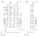
図1に示すように、振動素子1は、基部10と、基部10から延出している一対の駆動腕20,30などから構成されている。詳しくは、振動素子1は、略矩形平板状の基部10の+Y側の一端から、Y軸方向に互いに略平行に延びる角柱状の一対の駆動腕20,30を備えている。振動素子1を構成する基部10と駆動腕20,30は、一体で形成され、水晶が基材として用いられている。なお、本実施形態1の振動素子1は、フォトリソグラフィー法及びフッ素系ガスなどによるドライエッチング法で形成されている。
As shown in FIG. 1, the
水晶は、電気軸と呼ばれるX軸、機械軸と呼ばれるY軸および光学軸と呼ばれるZ軸を有している。振動素子1をなす基材は、水晶結晶軸において直交するX軸およびY軸で規定される平面に沿って切り出されて平板状に加工され、平面と直交するZ軸方向に所定の厚みを有している。Z軸は、X軸を中心に0度から2度の範囲で回転して切り出したものを使用することができる。所定の厚みは、振動周波数、外形サイズ、加工性などにより適宜設定される。
The crystal has an X axis called an electric axis, a Y axis called a mechanical axis, and a Z axis called an optical axis. The base material forming the
駆動腕20は、X軸方向の幅W1が広い幅広部22と、X軸方向の幅W2が狭い幅狭部26と、幅広部22から幅狭部26に向かってX軸方向の幅が漸減している傾斜部24a,24bと、を有している。駆動腕20には、基部10の+X側から駆動腕20の先端方向に向かって、幅広部22、傾斜部24a、幅狭部26、傾斜部24bの順に、繰り返し形成され、四つの幅広部22が設けられている。幅広部22と幅狭部26との間に、傾斜部24aまたは傾斜部24bを設けることにより駆動腕20の剛性を高めることができる。
The
駆動腕20の幅広部22に重なる位置には、Z軸方向に開口している貫通孔28が設けられている。駆動腕20に幅広部22を設けることにより、X軸方向に開口の広い貫通孔28を設けることができる。貫通孔28は、Y軸方向を長辺とする長方形の角部が丸められた角丸長方形を成している。角丸長方形の角丸部を、傾斜部24a,24bに沿わせて配置することにより、Y軸方向に開口の広い貫通孔28を設けることができる。
A through
駆動腕30は、X軸方向の幅W1が広い幅広部32と、X軸方向の幅W2が狭い幅狭部36と、幅広部32から幅狭部36に向かってX軸方向の幅が漸減している傾斜部34a,34bと、を有している。駆動腕30には、基部10の+X側から駆動腕30の先端方向に向かって、幅広部32、傾斜部34a、幅狭部36、傾斜部34bの順に、繰り返し形成され、四つの幅広部32が設けられている。幅広部32と幅狭部36との間に、傾斜部34aまたは傾斜部34bを設けることにより駆動腕30の剛性を高めることができる。
The driving
駆動腕30の幅広部32に重なる位置には、Z軸方向に開口している貫通孔38が設けられている。駆動腕30に幅広部32を設けることにより、X軸方向に開口の広い貫通孔38を設けることができる。貫通孔38は、Y軸方向を長辺とする長方形の角部が丸められた角丸長方形を成している。角丸長方形の角丸部を、傾斜部34a,34bに沿わせて配置することにより、Y軸方向に、開口の広い貫通孔38を設けることができる。
A through
駆動腕20,30の幅広部22,32に、X軸方向およびY軸方向に開口面積の広い貫通孔28,38を設けることができるため、振動素子1がドライエッチング法で形成される際のマイクロローディング効果によるエッチングレートの低下と、これによる生産効率の低下とを抑制することができる。
開口面積の大きい貫通孔28,38を形成させるために、所定周波数で振動する振動素子1の駆動腕20,30に幅広部22,32を設けた場合、振動素子1の振動周波数が所定周波数よりも上昇してしまう。従来、振動素子1の振動周波数を低下させるためには、駆動腕20,30のY軸方向の長さを長くする必要があったが、これは振動素子1の外形寸法の増大を招いてしまう。そこで、本実施形態では、振動素子1の駆動腕20,30に、振動周波数を低下させるための幅狭部26,36が設けられている。これにより、幅広部22,32による振動周波数の上昇を幅狭部26,36で抑えることができる。
Since the
When the
なお、幅広部22,32に重なる位置には、角丸長方形の貫通孔28,38を設けるものと説明したが、この形状に限定するものではない。例えば、貫通孔28,38は、長方形の少なくとも一つの角部が丸められた形状、角丸部を多角形で形成した形状、楕円形状などであってもよい。
In addition, although it demonstrated that the through-
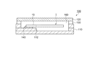
図2は、図1におけるA−A線での断面図である。
図2に示すように、駆動腕20のX軸方向の二つ外側面には、第1駆動電極42が形成されている。駆動腕20の幅広部22に重なる位置に設けられている貫通孔28のX軸方向の二つ内側面には、第2駆動電極44が形成されている。
駆動腕30のX軸方向の二つ外側面には、第2駆動電極44が形成されている。駆動腕30の幅広部32に重なる位置に設けられている貫通孔38のX軸方向の二つ内側面には、第1駆動電極42が形成されている。
FIG. 2 is a cross-sectional view taken along line AA in FIG.
As shown in FIG. 2,
A
第1駆動電極42と第2駆動電極44とに、位相が180度異なる交流電圧を印加すると、振動素子1は、駆動腕20と駆動腕30とが、面内方向(XY平面方向)に沿って互いに逆方向へ変位する屈曲運動を繰り返し、所定の周波数で屈曲振動する。
上述のように、駆動腕20,30に貫通孔28,38を設けることにより、貫通孔28,38の内側面と、駆動腕20,30の外側面に第1駆動電極42または第2駆動電極44を配置することができる。これにより、第1駆動電極42と第2駆動電極44との間で電界を効果的に発生させることができるので、インピーダンスの低い振動素子1が得られる。
When an alternating voltage having a phase difference of 180 degrees is applied to the
As described above, by providing the through
第1駆動電極42、第2駆動電極44の構成としては、特に限定されず、金(Au)、金合金、白金(Pt)、アルミニウム(Al)、アルミニウム合金、銀(Ag)、銀合金、クロム(Cr)、クロム合金、銅(Cu)、モリブデン(Mo)、ニオブ(Nb)、タングステン(W)、鉄(Fe)、チタン(Ti)、コバルト(Co)、亜鉛(Zn)、ジルコニウム(Zr)等の金属材料、酸化インジウムスズ(ITO)等の導電材料により形成することができる。
The configuration of the
図3は、幅狭部/幅広部と振動周波数と、幅狭部/幅広部とインピーダンスと、の関係を示すグラフである。
図3(a)に、幅狭部/幅広部と振動周波数との関係を示す。
図3(a)の横軸は、幅広部22,32のX軸方向の幅W1を基準に、幅狭部26,36のX軸方向の幅W2を比率(パーセント)で表している。
図3(a)の縦軸は、幅狭部26,36のX軸方向の幅W2と、幅広部22,32のX軸方向の幅W1と、が同じ場合(幅狭部26,36が無い場合)の振動周波数f0を基準とし、幅狭部26,36を設けたときの振動周波数fを基準化周波数で表している。
FIG. 3 is a graph showing the relationship between the narrow portion / wide portion and the vibration frequency, and the narrow portion / wide portion and the impedance.
FIG. 3A shows the relationship between the narrow part / wide part and the vibration frequency.
The horizontal axis of FIG. 3A represents the width W2 of the
The vertical axis in FIG. 3A is the case where the width W2 in the X-axis direction of the
図3(a)に示されているグラフは、振動素子1の幅狭部26,36の幅W2を幅広部22,32の幅W1に対して狭くした場合の振動周波数fの変化を表している。このグラフが示すように、幅狭部26,36の幅W2を幅広部22,32の幅W1の99%に僅かに狭くするだけでも振動素子1の振動周波数fを低下させる効果が確認できる。幅狭部26,36は、X軸方向に開口面積の大きい貫通孔28,38を設けるために駆動腕20,30に設けられた幅広部22,32によって上昇した振動周波数を、低下させることができる。
The graph shown in FIG. 3A represents a change in the vibration frequency f when the width W2 of the
図3(b)に、幅狭部/幅広部とインピーダンスとの関係を示す。
図3(b)の横軸は、幅広部22,32のX軸方向の幅W1を基準に、幅狭部26,36のX軸方向の幅W2を比率(パーセント)で表している。
図3(b)の縦軸は、幅狭部26,36のX軸方向の幅W2と、幅広部22,32のX軸方向の幅W1と、が同じ(幅狭部26,36が無い場合)で、且つ、貫通孔28,38が、設けられていない場合のインピーダンスR10を基準とし、幅狭部26,36と、貫通孔28,38と、を設けたときのインピーダンスR1を基準化インピーダンスで表している。
FIG. 3B shows the relationship between the narrow part / wide part and the impedance.
The horizontal axis of FIG. 3B represents the width W2 of the
3B, the width W2 in the X-axis direction of the
図3(b)において、ドットαは、駆動腕20,30に、幅狭部26,36、および貫通孔28,38が設けられていない時の基準インピーダンスR10(1.0)を示し、曲線βは、駆動腕20,30に貫通孔28,38を設け、振動素子1の幅狭部26,36の幅W2を幅広部22,32の幅W1に対して狭くした場合のインピーダンスR1の変化を表している。
曲線βに示すように、振動素子1のインピーダンスR1は、幅狭部26,36の幅を狭くすることにより上昇してしまう。しかし、本実施形態の振動素子1には、インピーダンスR1を低下させるための貫通孔28,38が設けられている。幅狭部26,36の幅W2を幅広部22,32の幅W1の88%以上とすることで、発明者が目標としていた、基準インピーダンスR10に対して50%以下という低インピーダンスの振動素子1を実現することができた。
In FIG. 3B, the dot α indicates the reference impedance R1 0 (1.0) when the
As indicated by the curve β, the impedance R1 of the
なお、本実施形態では、振動素子1は、水晶を基材に用いるものと説明したが、これに限定するものではない。振動素子1は、水晶以外にタンタル酸リチウム、ニオブ酸リチウム等の圧電単結晶や、ジルコン酸チタン酸鉛等の圧電セラミックス等の圧電材料、又はシリコン半導体材料から形成することができる。
In the present embodiment, it has been described that the
以上述べたように、本実施形態1に係る振動素子1よれば、以下の効果を得ることができる。
本実施形態の振動素子1は、+Z軸方向からの平面視にて、基部10の+Y側から+Y軸方向に平行に延出され面内方向(XY面内方向)に沿って振動可能な二つの駆動腕20,30を備えている。駆動腕20,30は、幅広部22,32と、幅狭部26,36と、傾斜部24a,24b,34a,34bと、を有している。幅広部22,32に設けられた開口面積の大きい貫通孔28,38は、振動素子1のインピーダンスを低下させると共に、マイクロローディング効果によるエッチングレートの低下と、これによる生産効率の低下とを抑制させることができる。幅狭部26,36は、幅広部22,32による振動周波数の上昇を、振動素子1の外形寸法を増大することなく、低下させることができる。したがって、小型で生産効率が高く、低インピーダンスの振動素子1を提供することができる。
As described above, according to the
The
<電子デバイス−1>
次に、本発明の振動素子1を適応した電子デバイスとしての音叉型振動子について説明する。図4は、本発明の振動素子1を備える音叉型振動子100の概略を示した断面図である。
<Electronic device-1>
Next, a tuning fork vibrator as an electronic device to which the
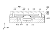
音叉型振動子100は、振動素子1、振動素子1を収容するために矩形の箱状に形成されているパッケージ本体110、および蓋体120を備えている。振動素子1は、セラミックなどで形成されたパッケージ本体110に形成された支持台112に、振動素子1の基部10が導電性接着剤などの固定部材140を介して接着支持されている。また、支持台112の表面には配線(図示せず)が形成され、振動素子1の第1駆動電極42および第2駆動電極44と、配線とは、固定部材140を介して電気的に接続されている。音叉型振動子100は、振動素子1に電圧を加えることで、振動子として機能する。
The
この固定部材140は、弾性のある材料であることが望ましい。弾性を有する固定部材140としてはシリコーンを基材とする接着剤などが知られている。パッケージ本体110の上部開口には封止部150が設けられており、パッケージ本体110と蓋体120とは、封止部150を介して封止されている。なお、振動素子1を収容するパッケージ本体110のキャビティー160は窒素などの不活性気体雰囲気あるいは減圧雰囲気となっている。
The fixing
以上述べたように、音叉型振動子100によれば、小型で生産効率が高く、低インピーダンスの振動素子1を備えた電子デバイスを提供することができる。
As described above, according to the
<電子デバイス−2>
次に、本発明の振動素子1を適応した電子デバイスとしての水晶発振器について説明する。図5は、本発明の振動素子1を備える水晶発振器200の概略を示した断面図である。
図5に示す水晶発振器200は、上述した音叉型振動子100の振動素子1の下方にICチップ230が配置されている。なお、音叉型振動子100(電子デバイス−1)と同一の構成部位については、同一の番号を附し、重複する説明は省略する。
<Electronic device-2>
Next, a crystal oscillator as an electronic device to which the
In the
水晶発振器200は、振動素子1、ICチップ230、振動素子1とICチップ230とを収納するための矩形の箱状に形成されているパッケージ本体210、および蓋体120を備えている。パッケージ本体210の底面にはICチップ230を収納するキャビティーが設けられており、キャビティー内にICチップ230が固定部材140を介して接着されている。パッケージ本体210の底面には配線(図示せず)が形成されており、ICチップ230と、配線と、がAu(金)などのワイヤー270で電気的に接続されている。水晶発振器200は、振動素子1が振動すると、その振動がICチップ230に入力され、その後、所定の周波数信号を取り出すことで、発振器として機能する。
The
以上述べたように、水晶発振器200によれば、小型で生産効率が高く、低インピーダンスの振動素子1を備えた電子デバイスを提供することができる。
As described above, according to the
(実施形態2)
<ジャイロセンサー素子>
図6(a)は、実施形態2に係るジャイロセンサー素子の概略構成を示す模式平面図である。図6(b)は、側面図である。図7は、図6におけるB−B線での断面図である。
まず、実施形態2に係るジャイロセンサー素子の概略構成について、図6と図7とを用いて説明する。なお、本実施形態のジャイロセンサー素子は、実施形態1で述べた振動素子1と同一構成の駆動腕20,30を備えている。振動素子1と同一の構成部位については、同一の番号を附し、重複する説明は省略する。
(Embodiment 2)
<Gyro sensor element>
FIG. 6A is a schematic plan view showing a schematic configuration of the gyro sensor element according to the second embodiment. FIG. 6B is a side view. FIG. 7 is a cross-sectional view taken along line BB in FIG.
First, a schematic configuration of the gyro sensor element according to the second embodiment will be described with reference to FIGS. 6 and 7. Note that the gyro sensor element of the present embodiment includes drive
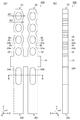
図6に示すように、ジャイロセンサー素子300は、基部10と、基部10から延出している一対の駆動腕20,30、および駆動腕20,30とは反対側の基部10から延出している一対の検出腕340,350などから構成されている。詳しくは、ジャイロセンサー素子300は、略矩形平板状の基部10の+Y側の一端から、+Y軸方向に互いに略平行に延びる角柱状の一対の駆動腕20,30と、基部10の−Y側の一端から−Y軸方向に互いに略平行に延びる角柱状の一対の検出腕340,350と、を備えている。
As shown in FIG. 6, the
検出腕340には、検出腕340の基部10側から検出腕340の先端側(−Y側)に向かって、Z軸方向に開口している貫通孔348が設けられている。貫通孔348は、Y軸方向を長辺とする長方形の角部が丸められた角丸長方形を成している。
検出腕350には、検出腕350の基部10側から検出腕350の先端側(−Y側)に向かって、Z軸方向に開口している貫通孔358が設けられている。貫通孔358は、Y軸方向を長辺とする長方形の角部が丸められた角丸長方形を成している。
なお、検出腕340,350には、角丸長方形の貫通孔348,358を設けるものと説明したが、この形状に限定するものではない。例えば、貫通孔348,358は、長方形、長方形の少なくとも一つの角部が丸められた形状、角丸部を多角形で形成した形状、楕円形状などであってもよい。
The
The
Although the
駆動腕20,30には、マイクロローディング効果によるエッチングレートの低下を防止するために、幅広部22,32が設けられ、幅広部22,32には、開口面積の広い貫通孔28,38が設けられている。駆動腕20,30に設けられた幅広部22,32は振動周波数の上昇を招き、駆動腕20,30の面内方向の面内振動周波数と検出腕340,350の面外方向の面外振動周波数とに周波数差が生じ、後述する角速度ωの検出感度が低下する。従来、これらの周波数を合わせるためには、駆動腕20,30の長さを長くする方法があったが、これは振動素子1の外形寸法の増大を招いてしまう。また、検出腕340,350の厚さ(Z軸方向)を厚くする方法があったが、これは生産効率と加工精度との低下を招いてしまう。そこで、本実施形態では、駆動腕20,30に、振動周波数を低下させるための幅狭部26,36が設けられている。これにより、駆動腕20,30の面内方向の面内振動周波数と検出腕340,350の面外方向の面外振動周波数とを略同じ周波数にすることができる。
The
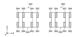
図7は、図6におけるB−B線での断面図である。
図7に示すように、検出腕340の+X軸方向の外側面には、外側面の+Z側に第1検出電極362が、外側面の−Z側に第2検出電極364が、形成されている。検出腕340の−X軸方向の外側面には、外側面の+Z側に第2検出電極364が、外側面の−Z側に第1検出電極362が、形成されている。
FIG. 7 is a cross-sectional view taken along line BB in FIG.
As shown in FIG. 7, the
検出腕340に設けられている貫通孔348の+X軸方向の内側面には、内側面の+Z側に第2検出電極364が、内側面の−Z側に第1検出電極362が、形成されている。検出腕340に設けられている貫通孔348の−X軸方向の内側面には、内側面の+Z側に第1検出電極362が、内側面の−Z側に第2検出電極364が、形成されている。
On the inner surface in the + X-axis direction of the through
検出腕350の+X軸方向の外側面には、外側面の+Z側に第2検出電極364が、外側面の−Z側に第1検出電極362が、形成されている。検出腕350の−X軸方向の外側面には、外側面の+Z側に第1検出電極362が、外側面の−Z側に第2検出電極364が、形成されている。
On the outer surface of the
検出腕350に設けられている貫通孔358の+X軸方向の内側面には、内側面の+Z側に第1検出電極362が、内側面の−Z側に第2検出電極364が、形成されている。検出腕350に設けられている貫通孔358の−X軸方向の内側面には、内側面の+Z側に第2検出電極364が、内側面の−Z側に第1検出電極362が、形成されている。
On the inner surface in the + X-axis direction of the through
次に、ジャイロセンサー素子300に加わる角速度の検出について説明する。
駆動腕20,30の第1駆動電極42と第2駆動電極44とに、位相が180度異なる交流電圧を印加すると、振動素子1は、駆動腕20と駆動腕30とが、面内方向(XY平面方向)に沿って互いに逆方向へ変位する屈曲振動(駆動モード)をする。本実施形態のジャイロセンサー素子300には、インピーダンスの低い駆動腕20,30が用いられているため、効率良く屈曲振動をさせることができる。この駆動モードの状態で、Y軸回りに角速度ωが加わると、駆動腕20,30にコリオリ力が発生し、駆動腕20,30が面内方向と交差する面外方向(+Z軸方向と−Z軸方向)に、互いに逆方向に屈曲振動する。
Next, detection of angular velocity applied to the
When an alternating voltage having a phase difference of 180 degrees is applied to the
検出腕340,350は、駆動腕20,30の面外方向の屈曲振動に共振して、同じく面外方向に、互いに逆方向に屈曲振動する。この時、圧電効果により第1検出電極362と、第2検出電極364との間に電荷が発生する。ジャイロセンサー素子300は、この電荷を検出することによりジャイロセンサー素子300に加わる角速度ωを検出することができる。
検出腕340,350には、貫通孔348,358が設けられ、検出腕340,350の外側面と貫通孔348,358の内側面とに、第1検出電極362および第2検出電極364を配置できる。これにより、第1検出電極362と第2検出電極364との間で電荷を効果的に発生させることができるので、検出感度の高いジャイロセンサー素子300が得られる。
The
The
以上述べたように、本実施形態2に係るジャイロセンサー素子300よれば、以下の効果を得ることができる。
本実施形態のジャイロセンサー素子300は、+Z軸方向からの平面視にて、基部10の+Y側から+Y軸方向に平行に延出され面内方向(XY面内方向)に沿って振動する二つの駆動腕20,30と、基部10の−Y側から−Y軸方向に平行に延出され面内方向と交差する面外方向の振動を検出する検出腕340,350と、を備えている。駆動腕20,30は、幅広部22,32と、幅狭部26,36と、傾斜部24a,24b,34a,34bと、を有している。幅広部22,32は、幅広部22,32に開口面積の大きい貫通孔28,38を設けることで、振動素子1のインピーダンスを低下させると共に、マイクロローディング効果によるエッチングレートの低下と、これによる生産効率の低下とを抑制することができる。幅狭部26,36は、幅広部22,32を設けることで生じた駆動腕20,30の振動周波数と検出腕340,350の振動周波数との周波数差を、駆動腕20,30の長さ、および検出腕340,350の厚さ、を増大させることなく、解消させることができる。したがって、小型で生産効率が高く、低インピーダンスのジャイロセンサー素子300を提供することができる。
As described above, according to the
The
<電子デバイス−3>
次に、本発明のジャイロセンサー素子300を適応した電子デバイスとしてのジャイロ装置について説明する。図8は、本発明のジャイロセンサー素子300を備えるジャイロ装置400の概略を示した断面図である。なお、音叉型振動子100(電子デバイス−1)と同一の構成部位については、同一の番号を附し、重複する説明は省略する。
<Electronic device-3>
Next, a gyro apparatus as an electronic device to which the
図8に示すように、ジャイロ装置400は、ジャイロセンサー素子300、ICチップ450、ジャイロセンサー素子300とICチップ450とを収容するために矩形の箱状に形成されているパッケージ本体410、および蓋体120を備えている。セラミックなどで形成されたパッケージ本体410の底面にはICチップ450が接着剤などの固定部材140を介して接着支持され、Au(金)などのワイヤー270でパッケージ本体410に形成された配線(図示せず)と電気的に接続されている。ICチップ450は、ジャイロセンサー素子300を駆動する駆動回路と、ジャイロセンサー素子300に加わった角速度ωを出力する検出回路とを含んでいる。
As shown in FIG. 8, the
ジャイロセンサー素子300は、ICチップ450を取り囲むようにパッケージ本体410に形成された支持台412上に固定された略枠状の基板440に支持されている。基板440は、ポリイミドなどの樹脂からなる基板本体430と、支持台412上に積層されたCu(銅)などの金属箔からなるタブテープ420と、を備えている。基板440は支持台412の縁から中央部に向かって斜め上方に折り曲げられた複数の帯状のタブテープ420が延設されている。タブテープ420の先端は、ジャイロセンサー素子300の基部10に形成された配線(図示せず)に、バンプなどの接合部材を介して電気的に接続されている。これにより、ジャイロセンサー素子300は、基板440によってXY平面に平行に支持されている。
The
ジャイロ装置400は、ICチップ450からの駆動信号によりジャイロセンサー素子300が所定の周波数で面内方向に沿って振動し、Y軸回りに角速度ωが加わることにより面外方向に振動する。この面外方向の振動により生じた電荷をICチップ450で検出することにより、ジャイロセンサーとして機能する。
In the
以上述べたように、ジャイロ装置400によれば、小型で生産効率が高く、低インピーダンスの振動素子1を備えた電子デバイスを提供することができる。
As described above, according to the
<電子機器>
次に、本発明の実施形態に係る振動素子1、音叉型振動子100、水晶発振器200、ジャイロセンサー素子300、またはジャイロ装置400を備えた電子機器について図9から図12を用いて説明する。なお、説明では、振動素子1を用いた例を示している。
<Electronic equipment>
Next, an electronic device including the
図9は、本発明の一実施形態に係る振動素子1を備える電子機器としてのモバイル型(又はノート型)のパーソナルコンピューター1100の構成の概略を示す斜視図である。この図において、パーソナルコンピューター1100は、キーボード1102を備えた本体部1104と、表示部1000を備えた表示ユニット1106とにより構成され、表示ユニット1106は、本体部1104に対しヒンジ構造部を介して回動可能に支持されている。このようなパーソナルコンピューター1100には、基準信号を出力するための振動素子1が内蔵されている。
FIG. 9 is a perspective view schematically illustrating a configuration of a mobile (or notebook)
図10は、本発明の一実施形態に係る振動素子1を備える電子機器としての携帯電話機1200(PHSも含む)の構成の概略を示す斜視図である。この図において、携帯電話機1200は、複数の操作ボタン1202、受話口1204および送話口1206を備え、操作ボタン1202と受話口1204との間には、表示部1000が配置されている。このような携帯電話機1200には、基準信号を出力するための振動素子1が内蔵されている。
FIG. 10 is a perspective view illustrating a schematic configuration of a mobile phone 1200 (including PHS) as an electronic apparatus including the
図11は、本発明の一実施形態に係る振動素子1を備える電子機器としてのデジタルスチルカメラ1300の構成の概略を示す斜視図である。なお、この図には、外部機器との接続についても簡易的に示されている。ここで、従来のフィルムカメラは、被写体の光像により銀塩写真フィルムを感光するのに対し、デジタルスチルカメラ1300は、被写体の光像をCCD(Charge Coupled Device)等の撮像素子により光電変換して撮像信号(画像信号)を生成する。
デジタルスチルカメラ1300におけるケース(ボディー)1302の背面には、表示部1000が設けられ、CCDによる撮像信号に基づいて表示を行う構成になっており、表示部1000は、被写体を電子画像として表示するファインダーとして機能する。また、ケース1302の正面側(図中裏面側)には、光学レンズ(撮像光学系)やCCD等を含む受光ユニット1304が設けられている。
撮影者が表示部1000に表示された被写体像を確認し、シャッターボタン1306を押下すると、その時点におけるCCDの撮像信号が、メモリー1308に転送・格納される。また、このデジタルスチルカメラ1300においては、ケース1302の側面に、ビデオ信号出力端子1312と、データ通信用の入出力端子1314とが設けられている。そして、図示されるように、ビデオ信号出力端子1312にはテレビモニター1430が、データ通信用の入出力端子1314にはパーソナルコンピューター1440が、それぞれ必要に応じて接続される。さらに、所定の操作により、メモリー1308に格納された撮像信号が、テレビモニター1430や、パーソナルコンピューター1440に出力される構成になっている。このようなデジタルスチルカメラ1300には、基準信号を出力するための振動素子1が内蔵されている。
FIG. 11 is a perspective view illustrating a schematic configuration of a
A
When the photographer confirms the subject image displayed on the
なお、本発明の一実施形態に係る振動素子1は、図9のパーソナルコンピューター1100(モバイル型パーソナルコンピューター)、図10の携帯電話機1200、図11のデジタルスチルカメラ1300の他にも、例えば、インクジェット式吐出装置(例えばインクジェットプリンター)、ラップトップ型パーソナルコンピューター、テレビ、ビデオカメラ、ビデオテープレコーダー、カーナビゲーション装置、ページャー、電子手帳(通信機能付も含む)、電子辞書、電卓、電子ゲーム機器、ワードプロセッサー、ワークステーション、テレビ電話、防犯用テレビモニター、電子双眼鏡、POS端末、医療機器(例えば電子体温計、血圧計、血糖計、心電図計測装置、超音波診断装置、電子内視鏡)、魚群探知機、各種測定機器、計器類(例えば、車両、航空機、船舶の計器類)、フライトシミュレーター等の電子機器に適用することができる。
Note that the
<移動体>
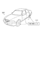
図12は移動体の一例としての自動車を概略的に示す斜視図である。自動車1500には本発明に係る振動素子1が搭載されている。例えば、同図に示すように、移動体としての自動車1500には、振動素子1を内蔵してタイヤなどを制御する電子制御ユニット1510が車体に搭載されている。また、振動素子1は、他にもキーレスエントリー、イモビライザー、カーナビゲーションシステム、カーエアコン、アンチロックブレーキシステム(ABS)、エアバック、タイヤ・プレッシャー・モニタリング・システム(TPMS:Tire Pressure Monitoring System)、エンジンコントロール、ハイブリッド自動車や電気自動車の電池モニター、車体姿勢制御システム、等の電子制御ユニット(ECU:Electronic Control Unit)に広く適用できる。
<Moving object>
FIG. 12 is a perspective view schematically showing an automobile as an example of a moving object. An
1…振動素子、10…基部、20,30…駆動腕、22,32…幅広部、24a,24b,34a,34b…傾斜部、26,36…幅狭部、28,38,348,358…貫通孔、42…第1駆動電極、44…第2駆動電極、100…音叉型振動子、110,210,410…パッケージ本体、112,412…支持台、120…蓋体、140…固定部材、150…封止部、200…水晶発振器、230,450…ICチップ、270…ワイヤー、300…ジャイロセンサー素子、340,350…検出腕、362…第1検出電極、364…第2検出電極、400…ジャイロ装置、420…タブテープ、430…基板本体、440…基板、1100…パーソナルコンピューター、1200…携帯電話機、1300…デジタルスチルカメラ、1500…自動車。
DESCRIPTION OF
Claims (9)
前記基部から延出され、貫通孔が設けられている駆動腕と、を備え、
前記駆動腕は、面内方向に沿って振動し、前記面内方向の幅が広い複数の幅広部と、前記面内方向の幅が狭い複数の幅狭部と、を交互に有し、
前記貫通孔は、前記幅広部に重なる位置に設けられていることを特徴とする振動素子。 The base,
A drive arm extending from the base and provided with a through hole,
The drive arm vibrates along an in-plane direction, and alternately has a plurality of wide portions having a wide width in the in-plane direction and a plurality of narrow portions having a narrow width in the in-plane direction,
The through-hole is provided at a position overlapping the wide portion.
前記駆動腕とは反対側の前記基部から延出され、前記面内方向と交差する面外方向の振動を検出する検出腕を備えていることを特徴とするジャイロセンサー素子。 The vibration element according to any one of claims 1 to 4 is provided as a drive arm,
A gyro sensor element comprising a detection arm that extends from the base opposite to the drive arm and detects vibration in an out-of-plane direction that intersects the in-plane direction.
Priority Applications (3)
| Application Number | Priority Date | Filing Date | Title |
|---|---|---|---|
| JP2014056091A JP2015179933A (en) | 2014-03-19 | 2014-03-19 | Vibration element, gyro sensor element, electronic device, electronic apparatus and moving body |
| US14/644,770 US9534894B2 (en) | 2014-03-19 | 2015-03-11 | Resonator element, gyro sensor element, electronic device, electronic apparatus, and moving object |
| CN201510119149.6A CN104935289A (en) | 2014-03-19 | 2015-03-18 | Resonator element, gyro sensor element, electronic device, electronic apparatus, and moving object |
Applications Claiming Priority (1)
| Application Number | Priority Date | Filing Date | Title |
|---|---|---|---|
| JP2014056091A JP2015179933A (en) | 2014-03-19 | 2014-03-19 | Vibration element, gyro sensor element, electronic device, electronic apparatus and moving body |
Publications (2)
| Publication Number | Publication Date |
|---|---|
| JP2015179933A true JP2015179933A (en) | 2015-10-08 |
| JP2015179933A5 JP2015179933A5 (en) | 2017-04-06 |
Family
ID=54122290
Family Applications (1)
| Application Number | Title | Priority Date | Filing Date |
|---|---|---|---|
| JP2014056091A Withdrawn JP2015179933A (en) | 2014-03-19 | 2014-03-19 | Vibration element, gyro sensor element, electronic device, electronic apparatus and moving body |
Country Status (3)
| Country | Link |
|---|---|
| US (1) | US9534894B2 (en) |
| JP (1) | JP2015179933A (en) |
| CN (1) | CN104935289A (en) |
Cited By (1)
| Publication number | Priority date | Publication date | Assignee | Title |
|---|---|---|---|---|
| JP2020191663A (en) * | 2017-05-25 | 2020-11-26 | 株式会社村田製作所 | Resonator and resonating device |
Families Citing this family (1)
| Publication number | Priority date | Publication date | Assignee | Title |
|---|---|---|---|---|
| WO2014119106A1 (en) * | 2013-01-29 | 2014-08-07 | 株式会社村田製作所 | Tuning-fork-type quartz vibrator |
Citations (5)
| Publication number | Priority date | Publication date | Assignee | Title |
|---|---|---|---|---|
| JP2003060482A (en) * | 2001-08-10 | 2003-02-28 | River Eletec Kk | Tuning fork crystal oscillating piece |
| JP2006208261A (en) * | 2005-01-31 | 2006-08-10 | Kyocera Kinseki Corp | Inertia sensor element |
| JP2008113098A (en) * | 2006-10-28 | 2008-05-15 | Nippon Dempa Kogyo Co Ltd | Tuning fork type piezoelectric vibration chip |
| JP2008209388A (en) * | 2006-10-13 | 2008-09-11 | Seiko Epson Corp | Acceleration sensor |
| JP2012029023A (en) * | 2010-07-23 | 2012-02-09 | Seiko Epson Corp | Bending vibration piece, vibrating gyro element, and electronic device |
Family Cites Families (6)
| Publication number | Priority date | Publication date | Assignee | Title |
|---|---|---|---|---|
| JP3973742B2 (en) | 1997-07-04 | 2007-09-12 | 日本碍子株式会社 | Vibrating gyroscope |
| JP3900846B2 (en) | 2001-03-02 | 2007-04-04 | セイコーエプソン株式会社 | Tuning fork type crystal vibrating piece, vibrator, oscillator and portable telephone device |
| JP4667858B2 (en) | 2004-12-28 | 2011-04-13 | 京セラキンセキ株式会社 | Inertial sensor element |
| JP2010193133A (en) * | 2009-02-18 | 2010-09-02 | Epson Toyocom Corp | Bending vibrator piece and bending vibrator |
| JP2012142666A (en) | 2010-12-28 | 2012-07-26 | Seiko Epson Corp | Vibration device and electronic apparatus |
| US20110227451A1 (en) | 2010-03-18 | 2011-09-22 | Seiko Epson Corporation | Resonator body, resonator device, and electronic device |
-
2014
- 2014-03-19 JP JP2014056091A patent/JP2015179933A/en not_active Withdrawn
-
2015
- 2015-03-11 US US14/644,770 patent/US9534894B2/en active Active
- 2015-03-18 CN CN201510119149.6A patent/CN104935289A/en active Pending
Patent Citations (5)
| Publication number | Priority date | Publication date | Assignee | Title |
|---|---|---|---|---|
| JP2003060482A (en) * | 2001-08-10 | 2003-02-28 | River Eletec Kk | Tuning fork crystal oscillating piece |
| JP2006208261A (en) * | 2005-01-31 | 2006-08-10 | Kyocera Kinseki Corp | Inertia sensor element |
| JP2008209388A (en) * | 2006-10-13 | 2008-09-11 | Seiko Epson Corp | Acceleration sensor |
| JP2008113098A (en) * | 2006-10-28 | 2008-05-15 | Nippon Dempa Kogyo Co Ltd | Tuning fork type piezoelectric vibration chip |
| JP2012029023A (en) * | 2010-07-23 | 2012-02-09 | Seiko Epson Corp | Bending vibration piece, vibrating gyro element, and electronic device |
Cited By (1)
| Publication number | Priority date | Publication date | Assignee | Title |
|---|---|---|---|---|
| JP2020191663A (en) * | 2017-05-25 | 2020-11-26 | 株式会社村田製作所 | Resonator and resonating device |
Also Published As
| Publication number | Publication date |
|---|---|
| US9534894B2 (en) | 2017-01-03 |
| US20150270825A1 (en) | 2015-09-24 |
| CN104935289A (en) | 2015-09-23 |
Similar Documents
| Publication | Publication Date | Title |
|---|---|---|
| US9748921B2 (en) | Electronic device, electronic apparatus, and moving object | |
| JP6107330B2 (en) | Vibration element, vibrator, oscillator, electronic device, and moving object | |
| JP6167520B2 (en) | Device manufacturing method | |
| JP6435606B2 (en) | Vibration element, vibrator, oscillator, electronic device, and moving object | |
| US9425768B2 (en) | Resonator element, resonator device, electronic apparatus, moving object, and method of manufacturing resonator element | |
| US9995582B2 (en) | Vibrating element, vibrating device, electronic apparatus, and moving object | |
| JP2014138413A (en) | Vibration element, vibrator, oscillator, electronic device, and mobile unit | |
| JP2016090254A (en) | Vibration element, electronic device, electronic equipment, and mobile body | |
| US9534894B2 (en) | Resonator element, gyro sensor element, electronic device, electronic apparatus, and moving object | |
| JP6498379B2 (en) | Vibration element, vibrator, oscillator, electronic device, and moving object | |
| JP6264839B2 (en) | Vibration element, vibrator, oscillator, electronic device, and moving object | |
| JP2016017768A (en) | Sensor element, sensor device, electronic equipment and mobile object | |
| JP2016186479A (en) | Physical quantity detection vibration element, physical quantity detection vibrator, electronic apparatus and mobile body | |
| JP6578709B2 (en) | Vibration element, vibrator, oscillator, electronic device, and moving object | |
| JP2014064078A (en) | Vibration piece, vibrator, electronic device, electronic apparatus, and mobile | |
| JP2016061710A (en) | Vibration element, gyro element, electronic device, electronic equipment, and mobile body | |
| JP2016044977A (en) | Sensor element, sensor device, electronic equipment, and mobile body | |
| JP6464667B2 (en) | Gyro element, gyro sensor, electronic device, and moving object | |
| JP6543889B2 (en) | Electronic device, electronic device and mobile | |
| JP2016133472A (en) | Service device, electronic apparatus, and mobile entity | |
| JP6264842B2 (en) | Vibration element, vibrator, oscillator, electronic device, and moving object | |
| JP2014175674A (en) | Vibrator, manufacturing method of vibrator, oscillator, electronic apparatus, and movable body | |
| JP2013195239A (en) | Sensor element, manufacturing method for sensor element, sensor device and electronic apparatus | |
| JP2016015563A (en) | Vibration element, electronic device, electronic apparatus and mobile body | |
| JP2016092466A (en) | Vibration element, method for manufacturing vibration element, electronic device, electronic equipment and mobile body |
Legal Events
| Date | Code | Title | Description |
|---|---|---|---|
| RD04 | Notification of resignation of power of attorney |
Free format text: JAPANESE INTERMEDIATE CODE: A7424 Effective date: 20160616 |
|
| RD03 | Notification of appointment of power of attorney |
Free format text: JAPANESE INTERMEDIATE CODE: A7423 Effective date: 20160624 |
|
| A521 | Request for written amendment filed |
Free format text: JAPANESE INTERMEDIATE CODE: A523 Effective date: 20170224 |
|
| A621 | Written request for application examination |
Free format text: JAPANESE INTERMEDIATE CODE: A621 Effective date: 20170224 |
|
| A977 | Report on retrieval |
Free format text: JAPANESE INTERMEDIATE CODE: A971007 Effective date: 20180130 |
|
| A131 | Notification of reasons for refusal |
Free format text: JAPANESE INTERMEDIATE CODE: A131 Effective date: 20180206 |
|
| A761 | Written withdrawal of application |
Free format text: JAPANESE INTERMEDIATE CODE: A761 Effective date: 20180404 |