JP2015128057A - Power storage body and electronic apparatus including the same - Google Patents
Power storage body and electronic apparatus including the same Download PDFInfo
- Publication number
- JP2015128057A JP2015128057A JP2014239451A JP2014239451A JP2015128057A JP 2015128057 A JP2015128057 A JP 2015128057A JP 2014239451 A JP2014239451 A JP 2014239451A JP 2014239451 A JP2014239451 A JP 2014239451A JP 2015128057 A JP2015128057 A JP 2015128057A
- Authority
- JP
- Japan
- Prior art keywords
- power storage
- storage unit
- electrode plate
- positive electrode
- exterior body
- Prior art date
- Legal status (The legal status is an assumption and is not a legal conclusion. Google has not performed a legal analysis and makes no representation as to the accuracy of the status listed.)
- Withdrawn
Links
Images


Classifications
-
- H—ELECTRICITY
- H05—ELECTRIC TECHNIQUES NOT OTHERWISE PROVIDED FOR
- H05K—PRINTED CIRCUITS; CASINGS OR CONSTRUCTIONAL DETAILS OF ELECTRIC APPARATUS; MANUFACTURE OF ASSEMBLAGES OF ELECTRICAL COMPONENTS
- H05K5/00—Casings, cabinets or drawers for electric apparatus
- H05K5/0086—Casings, cabinets or drawers for electric apparatus portable, e.g. battery operated apparatus
-
- H—ELECTRICITY
- H01—ELECTRIC ELEMENTS
- H01M—PROCESSES OR MEANS, e.g. BATTERIES, FOR THE DIRECT CONVERSION OF CHEMICAL ENERGY INTO ELECTRICAL ENERGY
- H01M10/00—Secondary cells; Manufacture thereof
- H01M10/04—Construction or manufacture in general
- H01M10/0463—Cells or batteries with horizontal or inclined electrodes
-
- H—ELECTRICITY
- H01—ELECTRIC ELEMENTS
- H01M—PROCESSES OR MEANS, e.g. BATTERIES, FOR THE DIRECT CONVERSION OF CHEMICAL ENERGY INTO ELECTRICAL ENERGY
- H01M50/00—Constructional details or processes of manufacture of the non-active parts of electrochemical cells other than fuel cells, e.g. hybrid cells
- H01M50/10—Primary casings, jackets or wrappings of a single cell or a single battery
- H01M50/116—Primary casings, jackets or wrappings of a single cell or a single battery characterised by the material
- H01M50/124—Primary casings, jackets or wrappings of a single cell or a single battery characterised by the material having a layered structure
-
- H—ELECTRICITY
- H01—ELECTRIC ELEMENTS
- H01M—PROCESSES OR MEANS, e.g. BATTERIES, FOR THE DIRECT CONVERSION OF CHEMICAL ENERGY INTO ELECTRICAL ENERGY
- H01M50/00—Constructional details or processes of manufacture of the non-active parts of electrochemical cells other than fuel cells, e.g. hybrid cells
- H01M50/10—Primary casings, jackets or wrappings of a single cell or a single battery
- H01M50/172—Arrangements of electric connectors penetrating the casing
- H01M50/174—Arrangements of electric connectors penetrating the casing adapted for the shape of the cells
- H01M50/178—Arrangements of electric connectors penetrating the casing adapted for the shape of the cells for pouch or flexible bag cells
-
- H—ELECTRICITY
- H01—ELECTRIC ELEMENTS
- H01M—PROCESSES OR MEANS, e.g. BATTERIES, FOR THE DIRECT CONVERSION OF CHEMICAL ENERGY INTO ELECTRICAL ENERGY
- H01M50/00—Constructional details or processes of manufacture of the non-active parts of electrochemical cells other than fuel cells, e.g. hybrid cells
- H01M50/10—Primary casings, jackets or wrappings of a single cell or a single battery
- H01M50/183—Sealing members
- H01M50/186—Sealing members characterised by the disposition of the sealing members
-
- H—ELECTRICITY
- H01—ELECTRIC ELEMENTS
- H01M—PROCESSES OR MEANS, e.g. BATTERIES, FOR THE DIRECT CONVERSION OF CHEMICAL ENERGY INTO ELECTRICAL ENERGY
- H01M50/00—Constructional details or processes of manufacture of the non-active parts of electrochemical cells other than fuel cells, e.g. hybrid cells
- H01M50/40—Separators; Membranes; Diaphragms; Spacing elements inside cells
- H01M50/409—Separators, membranes or diaphragms characterised by the material
- H01M50/411—Organic material
- H01M50/414—Synthetic resins, e.g. thermoplastics or thermosetting resins
- H01M50/417—Polyolefins
-
- H—ELECTRICITY
- H01—ELECTRIC ELEMENTS
- H01M—PROCESSES OR MEANS, e.g. BATTERIES, FOR THE DIRECT CONVERSION OF CHEMICAL ENERGY INTO ELECTRICAL ENERGY
- H01M50/00—Constructional details or processes of manufacture of the non-active parts of electrochemical cells other than fuel cells, e.g. hybrid cells
- H01M50/40—Separators; Membranes; Diaphragms; Spacing elements inside cells
- H01M50/409—Separators, membranes or diaphragms characterised by the material
- H01M50/411—Organic material
- H01M50/414—Synthetic resins, e.g. thermoplastics or thermosetting resins
- H01M50/42—Acrylic resins
-
- H—ELECTRICITY
- H01—ELECTRIC ELEMENTS
- H01M—PROCESSES OR MEANS, e.g. BATTERIES, FOR THE DIRECT CONVERSION OF CHEMICAL ENERGY INTO ELECTRICAL ENERGY
- H01M50/00—Constructional details or processes of manufacture of the non-active parts of electrochemical cells other than fuel cells, e.g. hybrid cells
- H01M50/40—Separators; Membranes; Diaphragms; Spacing elements inside cells
- H01M50/409—Separators, membranes or diaphragms characterised by the material
- H01M50/411—Organic material
- H01M50/414—Synthetic resins, e.g. thermoplastics or thermosetting resins
- H01M50/426—Fluorocarbon polymers
-
- H—ELECTRICITY
- H01—ELECTRIC ELEMENTS
- H01M—PROCESSES OR MEANS, e.g. BATTERIES, FOR THE DIRECT CONVERSION OF CHEMICAL ENERGY INTO ELECTRICAL ENERGY
- H01M50/00—Constructional details or processes of manufacture of the non-active parts of electrochemical cells other than fuel cells, e.g. hybrid cells
- H01M50/40—Separators; Membranes; Diaphragms; Spacing elements inside cells
- H01M50/409—Separators, membranes or diaphragms characterised by the material
- H01M50/411—Organic material
- H01M50/429—Natural polymers
-
- H—ELECTRICITY
- H01—ELECTRIC ELEMENTS
- H01M—PROCESSES OR MEANS, e.g. BATTERIES, FOR THE DIRECT CONVERSION OF CHEMICAL ENERGY INTO ELECTRICAL ENERGY
- H01M50/00—Constructional details or processes of manufacture of the non-active parts of electrochemical cells other than fuel cells, e.g. hybrid cells
- H01M50/40—Separators; Membranes; Diaphragms; Spacing elements inside cells
- H01M50/409—Separators, membranes or diaphragms characterised by the material
- H01M50/431—Inorganic material
- H01M50/434—Ceramics
- H01M50/437—Glass
-
- H—ELECTRICITY
- H01—ELECTRIC ELEMENTS
- H01M—PROCESSES OR MEANS, e.g. BATTERIES, FOR THE DIRECT CONVERSION OF CHEMICAL ENERGY INTO ELECTRICAL ENERGY
- H01M50/00—Constructional details or processes of manufacture of the non-active parts of electrochemical cells other than fuel cells, e.g. hybrid cells
- H01M50/40—Separators; Membranes; Diaphragms; Spacing elements inside cells
- H01M50/463—Separators, membranes or diaphragms characterised by their shape
- H01M50/466—U-shaped, bag-shaped or folded
-
- H—ELECTRICITY
- H01—ELECTRIC ELEMENTS
- H01M—PROCESSES OR MEANS, e.g. BATTERIES, FOR THE DIRECT CONVERSION OF CHEMICAL ENERGY INTO ELECTRICAL ENERGY
- H01M50/00—Constructional details or processes of manufacture of the non-active parts of electrochemical cells other than fuel cells, e.g. hybrid cells
- H01M50/50—Current conducting connections for cells or batteries
- H01M50/531—Electrode connections inside a battery casing
- H01M50/54—Connection of several leads or tabs of plate-like electrode stacks, e.g. electrode pole straps or bridges
-
- H—ELECTRICITY
- H01—ELECTRIC ELEMENTS
- H01G—CAPACITORS; CAPACITORS, RECTIFIERS, DETECTORS, SWITCHING DEVICES OR LIGHT-SENSITIVE DEVICES, OF THE ELECTROLYTIC TYPE
- H01G11/00—Hybrid capacitors, i.e. capacitors having different positive and negative electrodes; Electric double-layer [EDL] capacitors; Processes for the manufacture thereof or of parts thereof
- H01G11/04—Hybrid capacitors
- H01G11/06—Hybrid capacitors with one of the electrodes allowing ions to be reversibly doped thereinto, e.g. lithium ion capacitors [LIC]
-
- H—ELECTRICITY
- H01—ELECTRIC ELEMENTS
- H01M—PROCESSES OR MEANS, e.g. BATTERIES, FOR THE DIRECT CONVERSION OF CHEMICAL ENERGY INTO ELECTRICAL ENERGY
- H01M10/00—Secondary cells; Manufacture thereof
- H01M10/05—Accumulators with non-aqueous electrolyte
- H01M10/052—Li-accumulators
-
- H—ELECTRICITY
- H01—ELECTRIC ELEMENTS
- H01M—PROCESSES OR MEANS, e.g. BATTERIES, FOR THE DIRECT CONVERSION OF CHEMICAL ENERGY INTO ELECTRICAL ENERGY
- H01M10/00—Secondary cells; Manufacture thereof
- H01M10/05—Accumulators with non-aqueous electrolyte
- H01M10/052—Li-accumulators
- H01M10/0525—Rocking-chair batteries, i.e. batteries with lithium insertion or intercalation in both electrodes; Lithium-ion batteries
-
- H—ELECTRICITY
- H01—ELECTRIC ELEMENTS
- H01M—PROCESSES OR MEANS, e.g. BATTERIES, FOR THE DIRECT CONVERSION OF CHEMICAL ENERGY INTO ELECTRICAL ENERGY
- H01M10/00—Secondary cells; Manufacture thereof
- H01M10/05—Accumulators with non-aqueous electrolyte
- H01M10/058—Construction or manufacture
- H01M10/0585—Construction or manufacture of accumulators having only flat construction elements, i.e. flat positive electrodes, flat negative electrodes and flat separators
-
- H—ELECTRICITY
- H01—ELECTRIC ELEMENTS
- H01M—PROCESSES OR MEANS, e.g. BATTERIES, FOR THE DIRECT CONVERSION OF CHEMICAL ENERGY INTO ELECTRICAL ENERGY
- H01M12/00—Hybrid cells; Manufacture thereof
- H01M12/08—Hybrid cells; Manufacture thereof composed of a half-cell of a fuel-cell type and a half-cell of the secondary-cell type
-
- H—ELECTRICITY
- H01—ELECTRIC ELEMENTS
- H01M—PROCESSES OR MEANS, e.g. BATTERIES, FOR THE DIRECT CONVERSION OF CHEMICAL ENERGY INTO ELECTRICAL ENERGY
- H01M2220/00—Batteries for particular applications
- H01M2220/20—Batteries in motive systems, e.g. vehicle, ship, plane
-
- H—ELECTRICITY
- H01—ELECTRIC ELEMENTS
- H01M—PROCESSES OR MEANS, e.g. BATTERIES, FOR THE DIRECT CONVERSION OF CHEMICAL ENERGY INTO ELECTRICAL ENERGY
- H01M2220/00—Batteries for particular applications
- H01M2220/30—Batteries in portable systems, e.g. mobile phone, laptop
-
- H—ELECTRICITY
- H01—ELECTRIC ELEMENTS
- H01M—PROCESSES OR MEANS, e.g. BATTERIES, FOR THE DIRECT CONVERSION OF CHEMICAL ENERGY INTO ELECTRICAL ENERGY
- H01M4/00—Electrodes
- H01M4/02—Electrodes composed of, or comprising, active material
- H01M4/36—Selection of substances as active materials, active masses, active liquids
- H01M4/58—Selection of substances as active materials, active masses, active liquids of inorganic compounds other than oxides or hydroxides, e.g. sulfides, selenides, tellurides, halogenides or LiCoFy; of polyanionic structures, e.g. phosphates, silicates or borates
-
- H—ELECTRICITY
- H01—ELECTRIC ELEMENTS
- H01M—PROCESSES OR MEANS, e.g. BATTERIES, FOR THE DIRECT CONVERSION OF CHEMICAL ENERGY INTO ELECTRICAL ENERGY
- H01M50/00—Constructional details or processes of manufacture of the non-active parts of electrochemical cells other than fuel cells, e.g. hybrid cells
- H01M50/40—Separators; Membranes; Diaphragms; Spacing elements inside cells
- H01M50/409—Separators, membranes or diaphragms characterised by the material
- H01M50/411—Organic material
- H01M50/429—Natural polymers
- H01M50/4295—Natural cotton, cellulose or wood
-
- H—ELECTRICITY
- H01—ELECTRIC ELEMENTS
- H01M—PROCESSES OR MEANS, e.g. BATTERIES, FOR THE DIRECT CONVERSION OF CHEMICAL ENERGY INTO ELECTRICAL ENERGY
- H01M50/00—Constructional details or processes of manufacture of the non-active parts of electrochemical cells other than fuel cells, e.g. hybrid cells
- H01M50/40—Separators; Membranes; Diaphragms; Spacing elements inside cells
- H01M50/409—Separators, membranes or diaphragms characterised by the material
- H01M50/44—Fibrous material
-
- Y—GENERAL TAGGING OF NEW TECHNOLOGICAL DEVELOPMENTS; GENERAL TAGGING OF CROSS-SECTIONAL TECHNOLOGIES SPANNING OVER SEVERAL SECTIONS OF THE IPC; TECHNICAL SUBJECTS COVERED BY FORMER USPC CROSS-REFERENCE ART COLLECTIONS [XRACs] AND DIGESTS
- Y02—TECHNOLOGIES OR APPLICATIONS FOR MITIGATION OR ADAPTATION AGAINST CLIMATE CHANGE
- Y02E—REDUCTION OF GREENHOUSE GAS [GHG] EMISSIONS, RELATED TO ENERGY GENERATION, TRANSMISSION OR DISTRIBUTION
- Y02E60/00—Enabling technologies; Technologies with a potential or indirect contribution to GHG emissions mitigation
- Y02E60/10—Energy storage using batteries
-
- Y—GENERAL TAGGING OF NEW TECHNOLOGICAL DEVELOPMENTS; GENERAL TAGGING OF CROSS-SECTIONAL TECHNOLOGIES SPANNING OVER SEVERAL SECTIONS OF THE IPC; TECHNICAL SUBJECTS COVERED BY FORMER USPC CROSS-REFERENCE ART COLLECTIONS [XRACs] AND DIGESTS
- Y02—TECHNOLOGIES OR APPLICATIONS FOR MITIGATION OR ADAPTATION AGAINST CLIMATE CHANGE
- Y02E—REDUCTION OF GREENHOUSE GAS [GHG] EMISSIONS, RELATED TO ENERGY GENERATION, TRANSMISSION OR DISTRIBUTION
- Y02E60/00—Enabling technologies; Technologies with a potential or indirect contribution to GHG emissions mitigation
- Y02E60/13—Energy storage using capacitors
-
- Y—GENERAL TAGGING OF NEW TECHNOLOGICAL DEVELOPMENTS; GENERAL TAGGING OF CROSS-SECTIONAL TECHNOLOGIES SPANNING OVER SEVERAL SECTIONS OF THE IPC; TECHNICAL SUBJECTS COVERED BY FORMER USPC CROSS-REFERENCE ART COLLECTIONS [XRACs] AND DIGESTS
- Y02—TECHNOLOGIES OR APPLICATIONS FOR MITIGATION OR ADAPTATION AGAINST CLIMATE CHANGE
- Y02P—CLIMATE CHANGE MITIGATION TECHNOLOGIES IN THE PRODUCTION OR PROCESSING OF GOODS
- Y02P70/00—Climate change mitigation technologies in the production process for final industrial or consumer products
- Y02P70/50—Manufacturing or production processes characterised by the final manufactured product
Abstract
Description
本発明は、物、方法、または、製造方法に関する。または、本発明は、プロセス、マシン、マニュファクチャ、または、組成物(コンポジション・オブ・マター)に関する。例えば、本発明の一形態は、蓄電体、およびその作製方法等に関する。例えば、本発明の一形態は、蓄電体、半導体装置、表示装置、発光装置、記憶装置、それらの駆動方法、または、それらの製造方法等に関する。 The present invention relates to an object, a method, or a manufacturing method. Or this invention relates to a process, a machine, a manufacture, or a composition (composition of matter). For example, one embodiment of the present invention relates to a power storage unit, a manufacturing method thereof, and the like. For example, one embodiment of the present invention relates to a power storage unit, a semiconductor device, a display device, a light-emitting device, a memory device, a driving method thereof, a manufacturing method thereof, or the like.
リチウムイオン2次電池、リチウムイオンキャパシタ、空気電池等、種々の蓄電体の開発が盛んに行われている。特に高出力、高エネルギー密度であるリチウムイオン2次電池(例えば、特許文献1参照)は、半導体産業の発展に伴い急速にその需要が拡大している。充放電可能な蓄電体は、携帯電話やスマートフォン、ノート型パーソナルコンピュータ等の携帯情報端末、携帯音楽プレーヤ、デジタルカメラ等の電子機器、あるいは医療機器などの様々な電子機器の電力の供給源として現代の情報化社会に不可欠なものとなっている。 Various power storage units such as lithium ion secondary batteries, lithium ion capacitors, and air batteries are being actively developed. In particular, the demand for lithium ion secondary batteries (see, for example, Patent Document 1) having high output and high energy density is rapidly expanding with the development of the semiconductor industry. Chargeable / dischargeable power storage units are now used as power sources for various electronic devices such as portable information terminals such as mobile phones, smartphones, notebook personal computers, portable music players, digital cameras, and medical devices. It is indispensable to the information society.
また、近年、頭部に装着する表示装置など、人体や湾曲面に装着して使用される可撓性を有する表示装置が提案されている。また、湾曲面に装着可能な可撓性を有する蓄電体が求められている。特許文献2には、湾曲または屈曲することが可能な蓄電体が記載されている。 In recent years, flexible display devices such as a display device worn on the head and used on a human body or a curved surface have been proposed. There is also a need for a flexible power storage unit that can be mounted on a curved surface. Patent Document 2 describes a power storage unit that can be bent or bent.
本発明の一形態の課題は、新規な蓄電体、または新規なその作製方法等を提供することにある。例えば、本発明の一形態の課題は、曲げなどの変形に対して丈夫な蓄電体を提供すること、または、不良が起きにくい蓄電体を提供すること等である。 An object of one embodiment of the present invention is to provide a novel power storage unit or a novel manufacturing method thereof. For example, an object of one embodiment of the present invention is to provide a power storage unit that is strong against deformation such as bending, or to provide a power storage unit that is less prone to failure.
なお、複数の課題の記載は、互いの課題の存在を妨げるものではない。なお、本発明の一態様は、これらの課題の全て解決する必要はない。また、明細書、図面、請求項などの記載から、列記した以外の課題が自ずと明らかとなるものであり、これらの課題も本発明の一形態の課題となり得る。 Note that the description of a plurality of tasks does not disturb each other's existence. Note that one embodiment of the present invention does not have to solve all of these problems. In addition, problems other than those listed will be apparent from the description, drawings, claims, and the like, and these problems may be a problem of one embodiment of the present invention.
本発明の一形態は、第1の電極板と、第2の電極板と、絶縁体でなる第1のシートと、第1および第2の電極板を収納する外装体とを有し、2つ折りにされた第1のシートにより第1の電極板が覆われ、第1の電極板は、第1のシートと共に、外装体に固定されている蓄電体である。 One embodiment of the present invention includes a first electrode plate, a second electrode plate, a first sheet made of an insulator, and an exterior body that houses the first and second electrode plates. The first electrode plate is covered with a folded first sheet, and the first electrode plate is a power storage unit that is fixed to the exterior body together with the first sheet.
本発明の一形態は、第1の電極板と、第2の電極板と、絶縁体でなる2枚の第1のシートと、第1および第2の電極板を収納する外装体とを有し、前記2枚の第1のシートにより第1の電極板が覆われ、第1の電極板は、2枚の第1のシートと共に、外装体に固定されている蓄電体である。 One embodiment of the present invention includes a first electrode plate, a second electrode plate, two first sheets made of an insulator, and an exterior body that houses the first and second electrode plates. The first electrode plate is covered with the two first sheets, and the first electrode plate is an electric storage body fixed to the exterior body together with the two first sheets.
上記形態らにおいて、第2の電極板が外装体に固定されていることが可能である。または、上記形態らにおいて、絶縁体でなる2つ折りにされた第2のシートまたは、2枚の第2のシートにより、第2の電極板が覆われ、第2の電極板が、第2のシートと共に、外装体に固定されていることが可能である。 In the above-described embodiments, the second electrode plate can be fixed to the exterior body. Alternatively, in the above embodiment, the second electrode plate is covered with the second sheet or the two second sheets made of an insulator, and the second electrode plate is the second sheet. It is possible to be fixed to the exterior body together with the sheet.
本発明の一形態により、新規な蓄電体、または新規なその作製方法等を提供することができる。例えば、本発明の一形態により、曲げなどの変形に対して丈夫な蓄電体を提供すること、または、不良が起きにくい蓄電体を提供すること等が可能になる。 According to one embodiment of the present invention, a novel power storage unit, a novel manufacturing method thereof, or the like can be provided. For example, according to one embodiment of the present invention, it is possible to provide a power storage unit that is strong against deformation such as bending, or to provide a power storage unit that is less likely to be defective.
なお、これらの効果の記載は、他の効果の存在を妨げるものではない。また、本発明の一形態は、必ずしも、これらの効果の全てを有する必要はない。また、本発明の形態について、上記以外の課題、効果、および新規な特徴については、本明細書の記載および図面から自ずと明らかになるものである。 Note that the description of these effects does not disturb the existence of other effects. Further, one embodiment of the present invention does not necessarily have all of these effects. Moreover, about the form of this invention, the subject except the above, an effect, and a novel characteristic become clear naturally from description and drawing of this specification.
本明細書において、蓄電体とは、蓄電機能を有する素子及び装置全般を指すものである。例えば、蓄電体として、電池、一次電池、2次電池、リチウムイオン2次電池、リチウム空気2次電池、キャパシタ、リチウムイオンキャパシタなどがあげられる。また、電気化学デバイスとは、蓄電体、導電層、抵抗、容量素子などを利用することで機能しうる装置全般を指している。また、電子機器、電気機器、および機械装置等は、本発明の一形態に係る蓄電体を有している場合がある。 In this specification, a power storage unit refers to all elements and devices having a power storage function. For example, a battery, a primary battery, a secondary battery, a lithium ion secondary battery, a lithium air secondary battery, a capacitor, a lithium ion capacitor, or the like can be given as the power storage unit. An electrochemical device refers to all devices that can function by using a power storage unit, a conductive layer, a resistor, a capacitor, and the like. An electronic device, an electric device, a mechanical device, and the like may include the power storage body according to one embodiment of the present invention.
以下に、図面を用いて、本発明の実施の形態について詳細に説明する。ただし、本発明の実施の形態は以下の説明に限定されず、本発明の趣旨およびその範囲から逸脱することなくその形態および詳細を様々に変更し得ることは、当業者であれば容易に理解される。したがって、本発明の形態は、以下に示す実施の形態の記載内容に限定して解釈されるものではない。 Embodiments of the present invention will be described below in detail with reference to the drawings. However, embodiments of the present invention are not limited to the following description, and it is easily understood by those skilled in the art that the forms and details can be variously changed without departing from the spirit and scope of the present invention. Is done. Therefore, the present invention is not construed as being limited to the description of the embodiments below.
また、以下に複数の実施の形態を示すが、互いの実施の形態を適宜組み合わせることが可能である。また、1つの実施の形態の中に、いくつかの構成例が示される場合は、互いの構成例を適宜組み合わせることが可能である。 Moreover, although several embodiment is shown below, it is possible to combine each other's embodiment suitably. In addition, in the case where some structure examples are given in one embodiment, any of the structure examples can be combined as appropriate.
本発明の一形態に係る蓄電体は、正極および負極を有する。正極、負極は、それぞれ、シート状もしくは平板状の1つまたは複数の電極板(正極板、負極板)を有する。短絡を防止するため、隣接する2つの電極板の少なくとも一方は、その両面が絶縁体でなるシート(あるいは、フィルムと呼ぶこともできる。)で覆われている。以下の説明において、電極板を覆うシートを”セパレータ”と呼ぶ場合がある。
本実施の形態では、蓄電体の構成例、およびその作製方法例などを説明する。
A power storage unit according to one embodiment of the present invention includes a positive electrode and a negative electrode. Each of the positive electrode and the negative electrode has one or a plurality of electrode plates (a positive electrode plate and a negative electrode plate) each having a sheet shape or a flat plate shape. In order to prevent a short circuit, at least one of the two adjacent electrode plates is covered with a sheet (or may be referred to as a film) whose both surfaces are made of an insulator. In the following description, a sheet covering the electrode plate may be referred to as a “separator”.
In this embodiment, a structural example of a power storage unit, a manufacturing method example thereof, and the like will be described.
<<蓄電体の構成例1>>
図1−図16を参照して、蓄電体の構成例、およびその作製方法例などを説明する。
<< Configuration Example 1 of Power Storage Unit >>
A configuration example of a power storage unit, a manufacturing method example thereof, and the like will be described with reference to FIGS.
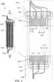
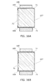
図1は蓄電体の構成例を示す上面図である。図2−図5は図1の断面図である。図2はA1−A2線断面図であり、図3はB1−B2線断面図であり、図4はC1−C2線断面図であり、図5はD1−D2線断面図である。図2−図5には、部分拡大図も示している。 FIG. 1 is a top view illustrating a configuration example of a power storage unit. 2 to 5 are sectional views of FIG. 2 is a sectional view taken along line A1-A2, FIG. 3 is a sectional view taken along line B1-B2, FIG. 4 is a sectional view taken along line C1-C2, and FIG. 5 is a sectional view taken along line D1-D2. 2 to 5 also show partial enlarged views.
図1に示すように、蓄電体300は、正極101、負極102、封止体104、封止体105、および外装体107を有する。ここでは、蓄電体300の一例として、外装体107の平面形態が四角形である構成を説明する。なお、本発明の形態の理解を容易にするため、上、下、左、右、縦、横等の用語を、参照している図面の図示の方法を基準に使用する場合がある。例えば、図1においては、正極101は外装体107の下側側面に存在しており、負極102は、その側面に対向する上側側面に存在していると、説明することができる。
As illustrated in FIG. 1, the
正極101および負極102は、蓄電体300の端子として機能する部分(101a、102a)を除いて、外装体107内に封入されている。外装体107内には、電解液103も封入されている(図2、図3)。以下では、部分101a、部分102aを、それぞれ、”端子部101a”、”端子部102a”と呼ぶことにする。
The
図1、図3に示すように、外装体107の対向する2つの側面(下側と上側の側面)の一方から、端子部101aが出ており、他方から端子部102aが出ている。蓄電体300の充電および放電は、端子部101aおよび端子部102aを介して行われる。端子部101aに正極用リードを接続することができる。端子部102aに負極用リードを接続することができる。
As shown in FIGS. 1 and 3, the
ここでは、蓄電体300の一例として、正極101は3つの正極板(111)を有し、負極102は4つの負極板(120、121)を有する構成を説明する(図2、図3)。正極板111は、正極集電体11および正極活物質層12を有し、負極板120と負極板121は、それぞれ負極集電体21および負極活物質層22を有する。端子部101aは、互いに電気的に接続された3つの正極集電体11で構成されている。端子部102aは、互いに電気的に接続された4つの負極集電体21で構成されている。複数の正極集電体11の電気的な接続、および複数の負極集電体21の電気的な接続は、例えば、これらを接合することで行うことができる。
Here, as an example of the
蓄電体300の各電極板(111、120、121)の両面は、セパレータ130で覆われている。セパレータ130は、例えば、2つ折りにされた1枚の絶縁体のシート30で構成することができる(図9参照)。セパレータ130については、後述する。ここでは、蓄電体300の一例として、正/負の両方の電極板がセパレータ130で覆われている構成について説明する。もちろん、本発明の一形態は、これに限定されず、正極板または負極板の何れか一方をセパレータ130で覆う構成にすることが可能である。
Both surfaces of each electrode plate (111, 120, 121) of the
外装体107は、例えば、1枚のフィルム70を2つに折り曲げることで作製できる(図15、図16)。フィルム70を袋状にするため、外装体107の3辺(左辺、上辺、下辺)に沿ってフィルム70同士を固定するための接合部71が形成されている。外装体107については後述する。
The
蓄電体300には、外装体107に挟まれた封止体104および封止体105が設けられている。図1、図3に示すように、封止体104は、正極101と外装体107の隙間を埋めるように、外装体107の下端に設けられている。封止体105は、負極102と外装体107の隙間を埋めるように、外装体107の上端に設けられている。接合部71の外装体107の下端に形成された部分において、外装体107は封止体104に固定されている。接合部71の外装体107の上端に形成された部分において、外装体107は封止体105に固定されている。図4は、接合部71における封止体104および正極101の断面構造を示し、図5は、接合部71における封止体105および負極102の断面構造を示している。
The
以下、図面を参照して、蓄電体300の構成要素の構成例、および蓄電体300の作製方法例を説明する。
Hereinafter, a configuration example of components of the
<電極板>
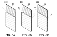
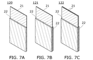
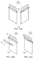
図6A−図6Cは、正極板の構成例を示す斜視図である。図7A−図7Cは、負極板の構成例を示す斜視図である。図8A−図8Cは、正極板、負極板の集電体の構成例を示す平面図である。
<Electrode plate>
6A to 6C are perspective views illustrating configuration examples of the positive electrode plate. 7A to 7C are perspective views illustrating configuration examples of the negative electrode plate. FIG. 8A to FIG. 8C are plan views showing a configuration example of a current collector of a positive electrode plate and a negative electrode plate.
正極板110は、正極集電体11および正極活物質層12を有する(図6A)。負極板120は、負極集電体21および負極活物質層22を有する(図7A)。正極板110、負極板120は、片面に活物質層が形成されている電極板である。
The
正極、負極とも、2つ以上の電極板で構成する場合、両面に活物質層が形成されている電極板が用いられる。正極板(111、112)、負極板(121、122)はこのような構成を持つ電極板である。正極板111には、1つの正極集電体11の両面に正極活物質層12が形成されている(図6B)。負極板121には、1つの負極集電体21の両面に負極活物質層22が形成されている(図7B)。正極板112は、2枚の正極板110を背中合わせにした構造の電極板に相当し、2枚の正極集電体11を有する(図6C)。負極板122は、2枚の負極板120を背中合わせにした構造の電極板に相当し、2枚の負極集電体21を有する(図7C)。ここでは、正極101は、3つの正極板111で構成されており、負極102は2つの負極板120と2つの負極板121で構成されている。
When both the positive electrode and the negative electrode are composed of two or more electrode plates, an electrode plate having an active material layer formed on both surfaces is used. The positive plates (111, 112) and the negative plates (121, 122) are electrode plates having such a configuration. In the
図8Aは正極集電体11の構成例を示す平面図である。図8Bは負極集電体21の構成例を示す平面図である。正極集電体11は、2つの部分(11a、11b)を有する。片面または両面に正極活物質層12が形成される部分が、部分11bである。部分11aには、正極活物質層12が形成されない。部分11aは、正極101の端子部101aを構成する。負極集電体21も、同様に、2つの部分(21a、21b)を有する。片面または両面に負極活物質層22が形成される部分が部分21bである。部分21aには、負極活物質層22が形成されない。部分21aは、負極102の端子部102aを構成する。ここでは、部分11aを”タブ11a”と呼び、部分21aを”タブ21a”と呼ぶことにする。
FIG. 8A is a plan view illustrating a configuration example of the positive electrode
図8Cは、電極板(111、120、121)を積層した状態を説明する図であり、集電体(11、21)の平面図である。負極活物質層22が形成される部分21bの縦、横のサイズを正極集電体11の部分11bよりも長くすることにより、正極板111、負極板(120、121)を積層した状態で、正極集電体11の周辺端部が、負極集電体21表面に存在するようにしている。このような構成により、負極板121の周辺端部で電界が集中するのを緩和することができるため、この領域でのウィスカーの析出が抑制される。これにより、蓄電体300の充放電サイクル寿命を延ばすことができる。
FIG. 8C is a diagram illustrating a state in which the electrode plates (111, 120, 121) are stacked, and is a plan view of the current collector (11, 21). In a state where the
或いは、負極活物質層22が正極活物質層12と確実に対向するように、部分21bの外形サイズを部分11bよりも小さくすることで、負極集電体21の周辺端部が正極集電体11と確実に重なるように、電極板(111、120、121)を重ねることが可能である。また、部分11bと部分21bを同じサイズにし、これらの周辺端部が一致するように、電極板(111、120、121)を重ねることも可能である。
Alternatively, by making the outer size of the
電極板(111、120、121)は、集電体、活物質層以外を有してもよい。以下、電極板(111、120、121)を構成する部材や材料等について説明する。 The electrode plates (111, 120, 121) may have other than the current collector and the active material layer. Hereinafter, members, materials, and the like constituting the electrode plates (111, 120, 121) will be described.
[正極集電体]
正極集電体11には、ステンレス、金、白金、アルミニウム、チタン等の金属、及びこれらの合金など、導電性が高く、リチウム等のキャリアイオンと合金化しない材料を用いることができる。また、シリコン、チタン、ネオジム、スカンジウム、モリブデンなどの耐熱性を向上させる元素が添加されたアルミニウム合金を用いることができる。また、シリコンと反応してシリサイドを形成する金属元素で形成してもよい。シリコンと反応してシリサイドを形成する金属元素としては、ジルコニウム、チタン、ハフニウム、バナジウム、ニオブ、タンタル、クロム、モリブデン、タングステン、コバルト、ニッケル等がある。正極集電体11には、箔状、板状、シート状、網状、パンチングメタル状、エキスパンドメタル状等の部材を適宜用いることができる。正極集電体11の厚さは、例えば、5μm以上30μm以下とすることができる。厚さを5μm以上10μm以下とすることで、蓄電体300を薄く、軽量化することができ、また、蓄電体300を曲げやすくすることができるので、好ましい。
[Positive electrode current collector]
For the positive electrode
また、正極集電体11の表面に、グラファイト等でなるアンダーコート層を設けもよい。
Further, an undercoat layer made of graphite or the like may be provided on the surface of the positive electrode
[正極活物質層]
正極活物質層12は、正極活物質の他、正極活物質の密着性を高めるための結着剤(バインダ)、正極活物質層12の導電性を高めるための導電助剤等を有してもよい。
[Positive electrode active material layer]
In addition to the positive electrode active material, the positive electrode
正極活物質としては、オリビン型の結晶構造、層状岩塩型の結晶構造、またはスピネル型の結晶構造を有する複合酸化物等がある。正極活物質として、例えば、LiFeO2、LiCoO2、LiNiO2、LiMn2O4、V2O5、Cr2O5、MnO2等の化合物を用いる。 Examples of the positive electrode active material include an olivine crystal structure, a layered rock salt crystal structure, and a composite oxide having a spinel crystal structure. As the positive electrode active material, for example, compounds such as LiFeO2, LiCoO2, LiNiO2, LiMn2O4, V2O5, Cr2O5, and MnO2 are used.
特に、LiCoO2は、容量が大きいこと、LiNiO2に比べて大気中で安定であること、LiNiO2に比べて熱的に安定であること等の利点があるため、好ましい。 Particularly, LiCoO 2 has the capacity is large, it is stable in the atmosphere as compared to LiNiO 2, because there are advantages such that it is thermally stable than LiNiO 2, preferred.
また、LiMn2O4等のマンガンを含むスピネル型の結晶構造を有する化合物に、少量のニッケル酸リチウム(LiNiO2やLiNi1−xMO2(M=Co、Al等))を混合すると、マンガンの溶出を抑制する、電解液の分解を抑制する等の利点があり好ましい。 Further, when a small amount of lithium nickelate (LiNiO 2 or LiNi 1-x MO 2 (M = Co, Al, etc.)) is mixed with a compound having a spinel crystal structure containing manganese such as LiMn 2 O 4 , manganese There are advantages such as suppression of elution and suppression of electrolyte decomposition.
また、正極活物質には、複合材料(一般式LiMPO4(Mは、Fe(II)、Mn(II)、Co(II)、Ni(II)の一以上))を用いることができる。一般式LiMPO4の代表例としては、LiFePO4、LiNiPO4、LiCoPO4、LiMnPO4、LiFeaNibPO4、LiFeaCobPO4、LiFeaMnbPO4、LiNiaCobPO4、LiNiaMnbPO4(a+bは1以下、0<a<1、0<b<1)、LiFecNidCoePO4、LiFecNidMnePO4、LiNicCodMnePO4(c+d+eは1以下、0<c<1、0<d<1、0<e<1)、LiFefNigCohMniPO4(f+g+h+iは1以下、0<f<1、0<g<1、0<h<1、0<i<1)等のリチウム化合物を材料として用いることができる。 For the positive electrode active material, a composite material (general formula LiMPO 4 (M is one or more of Fe (II), Mn (II), Co (II), and Ni (II))) can be used. Representative examples of the general formula LiMPO 4 include LiFePO 4 , LiNiPO 4 , LiCoPO 4 , LiMnPO 4 , LiFe a Ni b PO 4 , LiFe a Co b PO 4 , LiFe a Mn b PO 4 , LiNi a Co b PO 4 . LiNi a Mn b PO 4 (a + b is 1 or less, 0 <a <1, 0 <b <1), LiFe c Ni d Co e PO 4 , LiFe c Ni d M e PO 4 , LiNi c Co d Mn e PO 4 (c + d + e ≦ 1, 0 <c <1,0 <d <1,0 <e <1), LiFe f Ni g Co h Mn i PO 4 (f + g + h + i is 1 or less, 0 <f <1,0 < Lithium compounds such as g <1, 0 <h <1, 0 <i <1) can be used as the material.
特にLiFePO4は、安全性、安定性、高容量密度、高電位、初期酸化(充電)時に引き抜けるリチウムイオンの存在等、正極活物質に求められる事項をバランスよく満たしているため、好ましい。 In particular, LiFePO 4 is preferable because it satisfies the requirements for the positive electrode active material in a well-balanced manner, such as safety, stability, high capacity density, high potential, and the presence of lithium ions extracted during initial oxidation (charging).
また、正極活物質には、一般式Li(2−j)MSiO4(Mは、Fe(II)、Mn(II)、Co(II)、Ni(II)の一以上、0≦j≦2)等の複合材料を用いることができる。一般式Li(2−j)MSiO4の代表例としては、Li(2−j)FeSiO4、Li(2−j)NiSiO4、Li(2−j)CoSiO4、Li(2−j)MnSiO4、Li(2−j)FekNilSiO4、Li(2−j)FekColSiO4、Li(2−j)FekMnlSiO4、Li(2−j)NikColSiO4、Li(2−j)NikMnlSiO4(k+lは1以下、0<k<1、0<l<1)、Li(2−j)FemNinCoqSiO4、Li(2−j)FemNinMnqSiO4、Li(2−j)NimConMnqSiO4(m+n+qは1以下、0<m<1、0<n<1、0<q<1)、Li(2−j)FerNisCotMnuSiO4(r+s+t+uは1以下、0<r<1、0<s<1、0<t<1、0<u<1)等のリチウム化合物を材料として用いることができる。 The positive electrode active material includes a general formula Li (2-j) MSiO 4 (M is one or more of Fe (II), Mn (II), Co (II), Ni (II), 0 ≦ j ≦ 2). ) And the like can be used. Representative examples of the general formula Li (2-j) MSiO 4 include Li (2-j) FeSiO 4 , Li (2-j) NiSiO 4 , Li (2-j) CoSiO 4 , Li (2-j) MnSiO 4, Li (2-j) Fe k Ni l SiO 4, Li (2-j) Fe k Co l SiO 4, Li (2-j) Fe k Mn l SiO 4, Li (2-j) Ni k Co l SiO 4, Li (2- j) Ni k Mn l SiO 4 (k + l is 1 or less, 0 <k <1,0 <l <1), Li (2-j) Fe m Ni n Co q SiO 4, Li (2-j) Fe m Ni n Mn q SiO 4, Li (2-j) Ni m Co n Mn q SiO 4 (m + n + q is 1 or less, 0 <m <1,0 <n <1,0 <q <1), Li (2- j) Fe r Ni s Co t Mn u SiO 4 (r + s + t + u ≦ 1, 0 <r <1,0 <s <1,0 <t <1,0 <u <1) can be used a lithium compound such as a material.
また、正極活物質には、AxM2(XO4)3(A=Li、Na、Mg、M=Fe、Mn、Ti、V、Nb、Al、X=S、P、Mo、W、As、Si)の一般式で表されるナシコン型化合物を用いることができる。ナシコン型化合物としては、Fe2(MnO4)3、Fe2(SO4)3、Li3Fe2(PO4)3等がある。また、正極活物質として、Li2MPO4F、Li2MP2O7、Li5MO4(M=Fe、Mn)の一般式で表される化合物、NaFeF3、FeF3等のペロブスカイト型フッ化物、TiS2、MoS2等の金属カルコゲナイド(硫化物、セレン化物、テルル化物)、LiMVO4等の逆スピネル型の結晶構造を有する酸化物、バナジウム酸化物系(V2O5、V6O13、LiV3O8等)、マンガン酸化物、有機硫黄等の材料を用いることができる。 Also, the positive electrode active material includes AxM2 (XO4) 3 (A = Li, Na, Mg, M = Fe, Mn, Ti, V, Nb, Al, X = S, P, Mo, W, As, Si) The NASICON type compound represented by the general formula can be used. Examples of NASICON type compounds include Fe2 (MnO4) 3, Fe2 (SO4) 3, and Li3Fe2 (PO4) 3. Further, as a positive electrode active material, compounds represented by a general formula of Li2MPO4F, Li2MP2O7, Li5MO4 (M = Fe, Mn), perovskite fluorides such as NaFeF3 and FeF3, metal chalcogenides such as TiS2 and MoS2 (sulfides, selenium) And oxides having a reverse spinel crystal structure such as LiMVO4, vanadium oxides (V2O5, V6O13, LiV3O8, etc.), manganese oxides, organic sulfur, and the like can be used.
キャリアイオンが、リチウムイオン以外のアルカリ金属イオンや、アルカリ土類金属イオンの場合、正極活物質として、上記リチウム化合物、リチウム含有複合リン酸塩及びリチウム含有複合ケイ酸塩等において、リチウムの代わりに、アルカリ金属(例えば、ナトリウムやカリウム等)、アルカリ土類金属(例えば、カルシウム、ストロンチウム、バリウム、ベリリウム、マグネシウム等)を用いてもよい。例えば、NaFeO2や、Na2/3[Fe1/2Mn1/2]O2などのナトリウム含有層状酸化物を正極活物質として用いることができる。 When the carrier ion is an alkali metal ion other than lithium ion or alkaline earth metal ion, in the lithium compound, lithium-containing composite phosphate, lithium-containing composite silicate, etc. as the positive electrode active material, instead of lithium Alkali metals (for example, sodium and potassium) and alkaline earth metals (for example, calcium, strontium, barium, beryllium, magnesium, etc.) may be used. For example, a sodium-containing layered oxide such as NaFeO 2 or Na 2/3 [Fe 1/2 Mn 1/2 ] O 2 can be used as the positive electrode active material.
また、正極活物質には、上記材料を複数組み合わせた材料を用いてもよい。例えば、上記材料を複数組み合わせた固溶体を正極活物質として用いることができる。例えば、LiCo1/3Mn1/3Ni1/3O2とLi2MnO3の固溶体を用いることができる。 Further, a material obtained by combining a plurality of the above materials may be used for the positive electrode active material. For example, a solid solution obtained by combining a plurality of the above materials can be used as the positive electrode active material. For example, a solid solution of LiCo 1/3 Mn 1/3 Ni 1/3 O 2 and Li 2 MnO 3 can be used.
正極活物質層12の表面に炭素層や、酸化ジルコニウムなどの酸化物層を設けてもよい。炭素層や酸化物層を設けることで、電極の導電性を向上させることができる。正極活物質層12への炭素層の被覆は、正極活物質の焼成時にグルコース等の炭水化物を混合することで形成することができる。
A carbon layer or an oxide layer such as zirconium oxide may be provided on the surface of the positive electrode
粒状の正極活物質層12の一次粒子としては、平均粒径が50nm以上100μm以下のものを用いるとよい。
As the primary particles of the granular positive electrode
導電助剤としては、アセチレンブラック(AB)、グラファイト(黒鉛)粒子、カーボンナノチューブ、グラフェン、フラーレンなどを用いることができる。 As the conductive assistant, acetylene black (AB), graphite (graphite) particles, carbon nanotubes, graphene, fullerene, or the like can be used.
導電助剤により、正極活物質層12中に電子伝導のネットワークを形成することができる。導電助剤により、正極活物質どうしの電気伝導の経路を維持することができる。正極活物質層12中に導電助剤を添加することにより、高い電子伝導性を有する正極活物質層12を実現することができる。
The conductive auxiliary agent can form an electron conduction network in the positive electrode
グラフェンは、高い導電性を有するという優れた電気特性、及び柔軟性並びに機械的強度という優れた物理特性を有する。また、グラフェンは、負極活物質層22の導電助剤としても用いることができる。グラフェンを、導電助剤として用いることにより、活物質同士の接触点や、接触面積を増大させることができる。
Graphene has excellent electrical properties such as high electrical conductivity, and excellent physical properties such as flexibility and mechanical strength. Graphene can also be used as a conductive aid for the negative electrode
また、バインダとして、代表的なポリフッ化ビニリデン(PVDF)の他、ポリイミド、ポリテトラフルオロエチレン、ポリビニルクロライド、エチレンプロピレンジエンポリマー、スチレン−ブタジエンゴム、アクリロニトリル−ブタジエンゴム、フッ素ゴム、ポリ酢酸ビニル、ポリメチルメタクリレート、ポリエチレン、ニトロセルロース等を用いることができる。 In addition to typical polyvinylidene fluoride (PVDF), as a binder, polyimide, polytetrafluoroethylene, polyvinyl chloride, ethylene propylene diene polymer, styrene-butadiene rubber, acrylonitrile-butadiene rubber, fluorine rubber, polyvinyl acetate, poly Methyl methacrylate, polyethylene, nitrocellulose and the like can be used.
正極活物質層12の総量に対するバインダの含有量は、1wt%以上10wt%以下が好ましく、2wt%以上8wt%以下がより好ましく、3wt%以上5wt%以下がさらに好ましい。また、正極活物質層12の総量に対する導電助剤の含有量は、1wt%以上10wt%以下が好ましく、1wt%以上5wt%以下がより好ましい。
The content of the binder with respect to the total amount of the positive electrode
[負極集電体]
負極集電体21には、ステンレス、金、白金、亜鉛、鉄、銅、タンタル、チタン等の金属、及びこれらの合金など、導電性の高く、リチウム等のキャリアイオンと合金化しない材料を用いることができる。また、シリコン、チタン、ネオジム、スカンジウム、モリブデンなどの耐熱性を向上させる元素が添加されたアルミニウム合金を用いることができる。また、シリコンと反応してシリサイドを形成する金属元素で形成してもよい。シリコンと反応してシリサイドを形成する金属元素としては、ジルコニウム、チタン、ハフニウム、バナジウム、ニオブ、タンタル、クロム、モリブデン、タングステン、コバルト、ニッケル等がある。負極集電体21は、箔状、板状(シート状)、網状、パンチングメタル状、エキスパンドメタル状等の形状を適宜用いることができる。負極集電体21の厚さは、例えば、5μm以上30μm以下とすることができる。厚さを5μm以上20μm以下とすることで、蓄電体300を薄く、かつ軽量化することができ、さらに、蓄電体300を曲げやすくすることができるので、好ましい。
[Negative electrode current collector]
The negative electrode
また、負極集電体21の表面に、グラファイトなどを用いてアンダーコート層を設けてもよい。
Further, an undercoat layer may be provided on the surface of the negative electrode
[負極活物質層]
負極活物質層22は、負極活物質の他、負極活物質の密着性を高めるための結着剤(バインダ)、負極活物質層22の導電性を高めるための導電助剤等を有してもよい。
[Negative electrode active material layer]
In addition to the negative electrode active material, the negative electrode
負極活物質は、リチウムの溶解・析出、又はリチウムイオンの挿入・脱離が可能な材料であれば、特に限定されない。負極活物質の材料としては、リチウム金属やチタン酸リチウムの他、蓄電体の分野で一般的な炭素系材料や、合金系材料等が挙げられる。 The negative electrode active material is not particularly limited as long as it is a material that can dissolve and precipitate lithium, or can insert and desorb lithium ions. As a material for the negative electrode active material, in addition to lithium metal and lithium titanate, a carbon-based material or an alloy-based material that is common in the field of power storage units can be given.
リチウム金属は、酸化還元電位が低く(標準水素電極に対して−3.045V)、重量及び体積当たりの比容量が大きい(それぞれ3860mAh/g、2062mAh/cm3)ため、好ましい。 Lithium metal is preferable because it has a low redox potential (−3.045 V with respect to the standard hydrogen electrode) and a large specific capacity per weight and volume (3860 mAh / g and 2062 mAh / cm 3 , respectively).
炭素系材料としては、黒鉛、易黒鉛化性炭素(ソフトカーボン)、難黒鉛化性炭素(ハードカーボン)、カーボンナノチューブ、グラフェン、カーボンブラック等が挙げられる。黒鉛としては、メソカーボンマイクロビーズ(MCMB)、コークス系人造黒鉛、ピッチ系人造黒鉛等の人造黒鉛や、球状化天然黒鉛等の天然黒鉛が挙げられる。黒鉛は、リチウムイオンが層間に挿入されたときに(リチウム−黒鉛層間化合物の生成時に)、リチウム金属と同程度に卑な電位を示す(0.1乃至0.3V vs.Li/Li+)。これにより、リチウムイオン電池は高い作動電圧を示すことができる。さらに、黒鉛は、単位体積当たりの容量が比較的高い、体積膨張が小さい、安価である、リチウム金属に比べて安全性が高い等の利点を有するため、好ましい。 Examples of the carbon-based material include graphite, graphitizable carbon (soft carbon), non-graphitizable carbon (hard carbon), carbon nanotube, graphene, and carbon black. Examples of graphite include artificial graphite such as mesocarbon microbeads (MCMB), coke-based artificial graphite, and pitch-based artificial graphite, and natural graphite such as spheroidized natural graphite. Graphite exhibits a potential as low as that of lithium metal when lithium ions are inserted between layers (at the time of formation of a lithium-graphite intercalation compound) (0.1 to 0.3 V vs. Li / Li + ). . Thereby, the lithium ion battery can show a high operating voltage. Further, graphite is preferable because it has advantages such as relatively high capacity per unit volume, small volume expansion, low cost, and high safety compared to lithium metal.
負極活物質には、リチウムとの合金化・脱合金化反応により充放電反応を行うことが可能な合金系材料も用いることができる。例えば、キャリアイオンがリチウムイオンである場合、合金系材料としては、Al、Si、Ge、Sn、Pb、Sb、Bi、Ag、Zn、Cd、In、Ga等のうち少なくとも一つを含む材料が挙げられる。このような元素は炭素に対して容量が大きく、特にシリコンは理論容量が4200mAh/gと飛躍的に高い。このため、負極活物質にシリコンを用いることが好ましい。このような元素を用いた合金系材料としては、例えば、Mg2Si、Mg2Ge、Mg2Sn、SnS2、V2Sn3、FeSn2、CoSn2、Ni3Sn2、Cu6Sn5、Ag3Sn、Ag3Sb、Ni2MnSb、CeSb3、LaSn3、La3Co2Sn7、CoSb3、InSb、SbSn等が挙げられる。 As the negative electrode active material, an alloy-based material capable of performing a charge / discharge reaction by an alloying / dealloying reaction with lithium can also be used. For example, when the carrier ions are lithium ions, the alloy material includes a material containing at least one of Al, Si, Ge, Sn, Pb, Sb, Bi, Ag, Zn, Cd, In, Ga, and the like. Can be mentioned. Such an element has a large capacity with respect to carbon. In particular, silicon has a theoretical capacity of 4200 mAh / g. For this reason, it is preferable to use silicon for the negative electrode active material. Examples of alloy materials using such elements include Mg 2 Si, Mg 2 Ge, Mg 2 Sn, SnS 2 , V 2 Sn 3 , FeSn 2 , CoSn 2 , Ni 3 Sn 2 , and Cu 6 Sn 5. , Ag 3 Sn, Ag 3 Sb, Ni 2 MnSb, CeSb 3 , LaSn 3 , La 3 Co 2 Sn 7 , CoSb 3 , InSb, SbSn, and the like.
また、負極活物質には、SiO、SnO、SnO2、二酸化チタン(TiO2)、リチウムチタン酸化物(Li4Ti5O12)、リチウム−黒鉛層間化合物(LixC6)、五酸化ニオブ(Nb2O5)、酸化タングステン(WO2)、酸化モリブデン(MoO2)等の酸化物を用いることができる。 In addition, examples of the negative electrode active material include SiO, SnO, SnO 2 , titanium dioxide (TiO 2 ), lithium titanium oxide (Li 4 Ti 5 O 12 ), lithium-graphite intercalation compound (Li x C 6 ), and niobium pentoxide. An oxide such as (Nb 2 O 5 ), tungsten oxide (WO 2 ), or molybdenum oxide (MoO 2 ) can be used.
また、負極活物質には、リチウムと遷移金属の複窒化物である、Li3N型構造をもつLi3−xMxN(M=Co、Ni、Cu)を用いることができる。例えば、Li2.6Co0.4N3は大きな充放電容量(900mAh/g、1890mAh/cm3)を示し好ましい。 Further, the negative electrode active material, a double nitride of lithium and a transition metal, Li 3 with N-type structure Li 3-x M x N ( M = Co, Ni, Cu) can be used. For example, Li 2.6 Co 0.4 N 3 shows a large charge / discharge capacity (900 mAh / g, 1890 mAh / cm 3 ) and is preferable.
リチウムと遷移金属の複窒化物を用いると、負極活物質中にリチウムイオンを含むため、正極活物質としてリチウムイオンを含まないV2O5、Cr3O8等の材料と組み合わせることができ好ましい。なお、正極活物質にリチウムイオンを含む材料を用いる場合でも、あらかじめ正極活物質に含まれるリチウムイオンを脱離させておくことで、負極活物質としてリチウムと遷移金属の複窒化物を用いることができる。 When lithium and transition metal double nitride is used, since the negative electrode active material contains lithium ions, it can be combined with materials such as V 2 O 5 and Cr 3 O 8 that do not contain lithium ions as the positive electrode active material. . Even when a material containing lithium ions is used for the positive electrode active material, it is possible to use lithium and transition metal double nitride as the negative electrode active material by desorbing lithium ions contained in the positive electrode active material in advance. it can.
また、コンバージョン反応が生じる材料を負極活物質として用いることもできる。例えば、酸化コバルト(CoO)、酸化ニッケル(NiO)、酸化鉄(FeO)等の、リチウムと合金化反応を行わない遷移金属酸化物を負極活物質に用いてもよい。コンバージョン反応が生じる材料としては、さらに、Fe2O3、CuO、Cu2O、RuO2、Cr2O3等の酸化物、CoS0.89、NiS、CuS等の硫化物、Zn3N2、Cu3N、Ge3N4等の窒化物、NiP2、FeP2、CoP3等のリン化物、FeF3、BiF3等のフッ化物でも起こる。なお、上記フッ化物の電位は高いため、正極活物質として用いてもよい。 A material that causes a conversion reaction can also be used as the negative electrode active material. For example, a transition metal oxide that does not undergo an alloying reaction with lithium, such as cobalt oxide (CoO), nickel oxide (NiO), or iron oxide (FeO), may be used as the negative electrode active material. As a material causing the conversion reaction, oxides such as Fe 2 O 3 , CuO, Cu 2 O, RuO 2 and Cr 2 O 3 , sulfides such as CoS 0.89 , NiS and CuS, Zn 3 N 2 are further included. This also occurs in nitrides such as Cu 3 N and Ge 3 N 4 , phosphides such as NiP 2 , FeP 2 and CoP 3 , and fluorides such as FeF 3 and BiF 3 . Note that since the potential of the fluoride is high, it may be used as a positive electrode active material.
また、負極活物質の表面に、グラフェンを形成してもよい。例えば、負極活物質をシリコンとした場合、充放電サイクルにおけるキャリアイオンの吸蔵・放出に伴う体積の変化が大きいため、負極集電体21と負極活物質層22との密着性が低下し、充放電により電池特性が劣化してしまう。そこで、シリコンを含む負極活物質の表面にグラフェンを形成すると、充放電サイクルにおいて、シリコンの体積が変化しても、負極集電体21と負極活物質層22との密着性の低下を抑制することができ、電池特性の劣化が低減されるため好ましい。
Further, graphene may be formed on the surface of the negative electrode active material. For example, when the negative electrode active material is silicon, the volume change accompanying the insertion and extraction of carrier ions in the charge / discharge cycle is large, so that the adhesion between the negative electrode
また、負極活物質の表面に、酸化物等の被膜を形成してもよい。充電時において電解液の分解等により形成される被膜は、その形成時に消費された電荷量を放出することができず、不可逆容量を形成する。これに対し、酸化物等の被膜をあらかじめ負極活物質の表面に設けておくことで、不可逆容量の発生を抑制又は防止することができる。 Further, a film such as an oxide may be formed on the surface of the negative electrode active material. The film formed by the decomposition of the electrolytic solution during charging cannot release the amount of charge consumed during the formation, and forms an irreversible capacity. On the other hand, generation | occurrence | production of an irreversible capacity | capacitance can be suppressed or prevented by providing the coating films, such as an oxide, in the surface of a negative electrode active material previously.
このような負極活物質を被覆する被膜には、ニオブ、チタン、バナジウム、タンタル、タングステン、ジルコニウム、モリブデン、ハフニウム、クロム、アルミニウム若しくはシリコンのいずれか一の酸化膜、又はこれら元素のいずれか一とリチウムとを含む酸化膜を用いることができる。このような被膜は、従来の電解液の分解生成物により負極表面に形成される被膜に比べ、十分緻密な膜である。 The film covering such a negative electrode active material includes niobium, titanium, vanadium, tantalum, tungsten, zirconium, molybdenum, hafnium, chromium, aluminum, or an oxide film of any one of these elements. An oxide film containing lithium can be used. Such a film is a sufficiently dense film as compared with a film formed on the surface of the negative electrode by a conventional decomposition product of the electrolytic solution.
例えば、五酸化ニオブ(Nb2O5)は、電気伝導度が10−9S/cmと低く、高い絶縁性を示す。このため、酸化ニオブ膜は負極活物質と電解液との電気化学的な分解反応を阻害する。一方で、酸化ニオブのリチウム拡散係数は10−9cm2/secであり、高いリチウムイオン伝導性を有する。このため、リチウムイオンを透過させることが可能である。また、酸化シリコンや酸化アルミニウムを用いてもよい。 For example, niobium pentoxide (Nb 2 O 5 ) has a low electrical conductivity of 10 −9 S / cm and high insulation properties. For this reason, the niobium oxide film inhibits the electrochemical decomposition reaction between the negative electrode active material and the electrolytic solution. On the other hand, the lithium diffusion coefficient of niobium oxide is 10 −9 cm 2 / sec and has high lithium ion conductivity. For this reason, it is possible to permeate | transmit lithium ion. Further, silicon oxide or aluminum oxide may be used.
負極活物質を被覆する被膜の形成には、例えばゾル−ゲル法を用いることができる。ゾル−ゲル法とは、金属アルコキシドや金属塩等からなる溶液を、加水分解反応・重縮合反応により流動性を失ったゲルとし、このゲルを焼成して薄膜を形成する方法である。ゾル−ゲル法は液相から薄膜を形成する方法であるから、原料を分子レベルで均質に混合することができる。このため、溶媒の段階の金属酸化膜の原料に、黒鉛等の負極活物質を加えることで、容易にゲル中に活物質を分散させることができる。このようにして、負極活物質の表面に被膜を形成することができる。当該被膜を用いることで、蓄電体の容量の低下を防止することができる。 For example, a sol-gel method can be used to form a film covering the negative electrode active material. The sol-gel method is a method of forming a thin film by baking a solution comprising a metal alkoxide, a metal salt, or the like that has lost fluidity due to a hydrolysis reaction or a polycondensation reaction. Since the sol-gel method is a method of forming a thin film from a liquid phase, raw materials can be homogeneously mixed at a molecular level. For this reason, the active material can be easily dispersed in the gel by adding a negative electrode active material such as graphite to the raw material of the metal oxide film at the solvent stage. In this way, a film can be formed on the surface of the negative electrode active material. By using the coating film, it is possible to prevent a reduction in the capacity of the power storage unit.
<電極板の作製>
塗布法等を用いて、正極活物質層12を形成することができる。例えば、正極活物質とバインダと導電助剤を混合して正極ペースト(スラリー)を作製する。正極集電体11を構成する導電体でなる箔(例えば、アルミニウム箔)の両面に正極ペーストを塗布し、乾燥させる。正極活物質層12が形成されたアルミニウム箔を加工する。この加工は、例えば、打ち抜き器を使用すればよい。以上の工程で、正極板111を作製することができる。負極板120、121も同様に作製することができる。負極集電体21には、例えば、銅箔を用いればよい。負極板120を形成する場合は、銅箔の片面に負極ペーストを塗布し、負極板121を形成する場合は、銅箔の両面に負極ペーストを塗布する。
<Production of electrode plate>
The positive electrode
<セパレータ>
図9に示すように、セパレータ130は、2つ折りにされた1枚の絶縁体でなるシート30から作製することができる。シート30には、ポリプロピレン(PP)、ポリエチレン(PE)、ポリブテン、ナイロン、ポリエステル、ポリスルホン、ポリアクリロニトリル、ポリフッ化ビニリデン、テトラフルオロエチレン等の多孔性絶縁体でなるシートを用いることができる。また、絶縁材料でなる繊維(ガラス繊維、高分子繊維、セルロース)で形成された不織布を用いることができる。また、シート30は、複数のシートを積層したシートでもよい。また、樹脂材料等で表面をコートして、耐熱性や、親水性を向上させてもよい。シート30の厚さは、例えば、10μm以上50μm以下とすればよい。
<Separator>
As shown in FIG. 9, the
図9を参照して、正極板111を覆うセパレータ130の作製方法の一例を説明する。シート30に折り目30aを形成する(図9A)。シート30上に正極板111を重ねる(図9B)。次いで、シート30を折り目30aで折り、シート30で正極板111を挟む(図9C)。これにより、正極板111の両面(上面、下面)がシート30で覆われた状態になる。ここでは、この状態を維持するため、シート30が重なっている領域(正極板111の左、右の外周部)でシート30同士を接合する。シート30の接合方法は、加熱による溶着、超音波接合、接着剤による接着等が挙げられる。接合方法は、シート30、電解液103等の材料によって適宜選択すればよい。
With reference to FIG. 9, an example of a manufacturing method of the
以上の工程で、セパレータ130が完成する。セパレータ130は、袋状あるいはエンベロープ状の絶縁体のシート30と呼ぶことが可能である。接合部31、32を形成することで、セパレータ130を正極板111により密着することができる。そのため、セパレータ130から正極板111がずれることを防止することができる。また、セパレータ130にしわが発生することを防止することができる。
The
図9の例では、1枚のシートからセパレータを形成したが、2枚のシートからセパレータを形成することもできる。2枚のシート30で、正極板111を挟む(図10A)。2枚のシート30を接合することで、セパレータ131が完成する(図10B)。図10Bの例では、セパレータ131には、セパレータ130と同様に、接合部31、32が形成され、さらに、図9Aのシート30の折り目30aに対応する部分に接合部33が形成されている。
In the example of FIG. 9, the separator is formed from one sheet, but the separator can also be formed from two sheets. The
なお、シート30をエンベロープ状(袋状)にするために形成される接合部は、図9D、図10Bの構成に限定されるものではない。正極板111が1枚または2枚のシート30で覆われるように、セパレータ130、131が作製できればよい。以下、図11を参照して、いくつかの構成例を説明する。例えば、セパレータ130において、タブ11aと重なる領域以外を除く外周部(シート30の左右の外周部)に、開口が残らないように、接合部31、接合部32を形成することができる(図11A)。また、セパレータ130の外周部に、一部に開口35が存在するように接合部31、32を形成することが可能である(図11B)。
In addition, the junction part formed in order to make the sheet |
正/負両方の電極板をセパレータで覆うことで、電極板間の短絡の防止効果が向上する。この場合、セパレータを構成する絶縁体のシートを、正極用と負極用に異ならせることが可能である。例えば、負極用では、析出物の除去のため、セルロース等の不織布でなるセパレータを使用する。正極用は、シャットダウン機能を有する多孔性の樹脂シートでなるセパレータを用いる。これにより、蓄電体の安全性を向上することができる。 Covering both the positive and negative electrode plates with a separator improves the effect of preventing a short circuit between the electrode plates. In this case, the insulating sheet constituting the separator can be made different for the positive electrode and the negative electrode. For example, for the negative electrode, a separator made of a nonwoven fabric such as cellulose is used to remove precipitates. For the positive electrode, a separator made of a porous resin sheet having a shutdown function is used. Thereby, the safety | security of an electrical storage body can be improved.
正/負の一方の電極板をセパレータで覆うことで、正/負両方の電極板をセパレータで覆うよりも、蓄電体を薄く、軽量化することができる。例えば、蓄電体の製造後の充放電によるエージング工程でガスが発生する場合がある。この場合、ガス抜きを容易にするために、ガスが発生しやすい方の電極板をセパレータで覆わない構成とすればよい。例えば、蓄電体300の使用時では、充放電を繰り返すことで、特性を劣化させるような析出物が生じやすい場合がある。この場合、正極と負極間の短絡の防止をより効果的にするために、析出物が生じやすい電極板の方をセパレータで覆う構成とすればよい。例えば、リチウムイオン2次電池の場合は、負極板にリチウムのウィスカーが形成される場合があるので、負極板をセパレータで覆う構成が好ましい。
By covering one of the positive / negative electrode plates with the separator, the power storage unit can be made thinner and lighter than when both the positive / negative electrode plates are covered with the separator. For example, gas may be generated in an aging process by charging / discharging after manufacturing the power storage unit. In this case, in order to facilitate degassing, the electrode plate on which gas is likely to be generated may be configured not to be covered with the separator. For example, when the
<電極積層体、封止体>
次に、負極板(120、121)と正極板(111)を交互に積層し、複数の電極板を含む電極積層体を形成する。本実施の形態では、電極積層体には、封止体104を形成するための部材を隣接する正極板の間に設け、また、封止体105を形成するための部材を負極板と負極板の間に設ける。ここでは、一例として、封止体104、105を絶縁体でなる融着テープで形成する例を説明する。
<Electrode laminated body, sealed body>
Next, the negative electrode plates (120, 121) and the positive electrode plate (111) are alternately stacked to form an electrode stack including a plurality of electrode plates. In the present embodiment, the electrode laminate is provided with a member for forming the sealing
電極板(111、120、121)を積層する前に、各電極板に融着テープを取り付ける。ここでは、正極板111を例に融着テープを取り付ける方法を説明する。負極板(120、121)についても同様である。図12Aに示すように、融着テープ50は、エンベロープ状のセパレータ130の解放端部と重なるように正極板111に取り付けられており、タブ11aおよびセパレータ130に取り付けられている。正極板111において、融着テープ50と重なる部分には正極活物質層12が形成されていないことが好ましい。図12Aは、正極板111の片面に融着テープ50を取り付ける例を示しており、正極板111の両面を図示している。また、図12B、図12Cに示すように、正極板111の両面に融着テープ50を取り付けることもできる。また、正極板111の片面、あるいは両面に2層以上融着テープ50を取り付けることができる。正極板111、シート30、および融着テープ50の厚さに応じて、融着テープ50の取り付け方法を決定することができる。電極積層体の最上層と最下層の電極板には、両面に融着テープを取り付ける。これにより、外装体と電極板のタブとの隙間を封止体で埋めることができる。
Before laminating the electrode plates (111, 120, 121), a fusion tape is attached to each electrode plate. Here, a method of attaching a fusion tape will be described taking the
図13Aに示すように、融着テープ50を取り付けた電極板(111、120、121)を積層する。ここでは、一番上の電極板(111、120)の両面に融着テープ50を取り付けてある。タブ11a同士、タブ21a同士が重なるように、負極板(120、121)と正極板(111)を交互に積層し、電極積層体180(図13B)を作製する。電極積層体180において、タブ11aに取り付けられた融着テープ50同士が融着することで封止体104が形成される。タブ21aに取り付けられた融着テープ50同士が融着することで、封止体105が形成される。
As shown in FIG. 13A, electrode plates (111, 120, 121) to which the
また、図14に示すように、封止体104、封止体105に、それぞれ、さらに融着テープ51を取り付けてもよい。融着テープ51は、封止体104、封止体105を構成することになる。封止体104、封止体105の何れか一方に融着テープ51を取り付けることも可能である。融着テープ50、51としては、粘着部が合成ゴム等の絶縁性および防水性を有する材料でなるテープを用いればよい。
Further, as shown in FIG. 14, a
封止体104、封止体105を構成する部材は、融着テープ50に限定されるものでない。隣接する2つの集電体(タブ)間、および集電体(タブ)と外装体の隙間を埋めて、電解液が漏れないように封止体104、105が形成できる絶縁体でなる部材、または材料等であればよい。例えば、絶縁性のシーリング材を用いることができる。シーリング材のように流動性を有する部材を用いる場合は、あらかじめ電極板に部材を塗布してもよいし、電極板を積層しながら、電極板に部材を塗布することもできる。
The members constituting the sealing
<外装体>
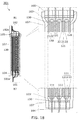
外装体107中に、電極積層体180を封止する。この封止工程では、タブ11a、21aが外装体107の外部に露出するように、外装体107が形成される。ここでは、1枚のフィルム70を折り、袋状に成形することで、外装体107を形成する(図15、図16)。外装体107を形成するためのフィルム70としては、金属フィルム(アルミニウム、ステンレス、ニッケル鋼など)、有機材料からなるプラスチックフィルム、有機材料(有機樹脂や繊維など)と無機材料(セラミックなど)とを含むハイブリッド材料フィルム、および、炭素含有フィルム(カーボンフィルム、グラファイトフィルムなど)から選ばれる単層フィルムを用いることができる。また、フィルム70としてはこれらのフィルムを複数積層させた積層フィルムを用いることができる。フィルム70として、凹部および/または凸部が形成されたフィルムを用いてもよい。これにより、フィルム70のフィルムの表面積が増えるため、外装体107を放熱効果の高めることができる。凹部および/または凸部の形成は、例えば、エンボス加工で行うことができる。
<Exterior body>
The
蓄電体300が変形した場合、外装体107に曲げ応力が加わり、その一部にしわなどの変形や、破壊が生じる恐れがある。外装体107に凹部および/または凸部を形成することにより、外装体107で生じた応力によるひずみを緩和することができる。これにより、蓄電体300の信頼性を高めることができる。ひずみとは物体の基準(初期状態)長さに対する物体内の物質点の変位を示す変形の尺度である。
When the
外装体107を形成するには、電極積層体180の外形に合わせて、フィルム70を折り曲げる、または凹部(凸部)を形成する。ここでは、図15Aに示すように、フィルム70に折り目70aを形成する。そして、フィルム70上に電極積層体180を重ね(図15B)、折り目70aでフィルムを折り曲げる(図15C)。例えば熱圧着等により、フィルム70の外周部を接合し、外装体107を形成する。この工程では、電解液103の導入口72を残すように、フィルム70の接合部71が形成される(図16A)。この工程で、フィルム70が封止体104、105に接合されるため、電極積層体180がフィルム70(外装体107)に固定されることになる。
In order to form the
図16Aは、接合部71は、外装体107の周囲の上部と下部の2か所に形成し、外装体107の左側側面は解放端として導入口72とする作製例を示している。蓄電体300のサイズが大きい等、場合によっては、図16Bに示すように、外装体107の左側側面の一部に導入口72を形成することもできる。
FIG. 16A shows a manufacturing example in which the
<端子部>
外装体107の外部に取り出されているタブ11a同士、およびタブ11b同士を電気的に接続し、正極101の端子部101a、および負極102の端子部102aを形成する(図1、図3等)。これらの電気的な接続は、超音波溶接で行うとよい。また、端子部101aおよび端子部102aの形成は、電極積層体180を外装体107で封止する前に行うことも可能である。
<Terminal part>
The
図3の例では、正極101の端子部101aを形成するため、最も左側にある正極板111のタブ11a(正極集電体11)が位置合わせの基準に用いられている。このタブ11aは曲げずに、他の2つのタブ11aを左方向に曲げることで、3つのタブ11a同士を接合して、端子部101aを形成している。また、負極102の端子部102aも同様である。最も左側にある負極板120のタブ21a(負極集電体21)は曲げずに、他の3つのタブ21aを左方向に曲げることで、4つのタブ21a同士を接合して形成されている。この例では、右側2つのタブ11aは、封止体104の固定部から、タブ11a同士の接合部にわたって、略S字状、略円弧状、あるいは弓状の湾曲部を有している。また、右側3つのタブ21aは、タブ21a同士の接合部から封止体105による固定部にわたって、略S字状、略円弧状、あるいは弓状の湾曲部を有している。もちろん、タブ11a、21aの湾曲形状は、図3の例に限定されるものでない。
In the example of FIG. 3, in order to form the
このように湾曲部が形成されるように、タブ11a同士、およびタブ21a同士をそれぞれ接合することで、曲げに対して壊れにくい蓄電体300とすることができる。特に、タブ11aおよびタブ21aの湾曲部を伸張させるような外装体107の変形に対して強い構造となる。図3の図示の方法では、外装体107の右側平面が凸状になるように(図2の図示の方法では、上側が凸になるように)、外装体107を曲げる、あるいはたわませるような変形に対して、特に強い構造となっている。そのため、蓄電体300は、蓄電体7407(図20C)のように、一方向に曲げることが可能な電子機器の蓄電体に好適である。また、蓄電体300は、蓄電体7104(図20E)のように、曲げられた、あるいはたわませた状態で筐体に組み込まれる蓄電体に好適である。すなわち、蓄電体300は、曲げられた電子機器の蓄電体に好適である。
By connecting the
<電解液>
減圧雰囲気下、或いは不活性ガス雰囲気下で電解液103を導入口72から外装体107の内部に注入し、セパレータ130を電解液103に含浸させる。
<Electrolyte>
The
電解液103としては、非プロトン性有機溶媒が好ましく、例えば、エチレンカーボネート(EC)、プロピレンカーボネート(PC)、ブチレンカーボネート、クロロエチレンカーボネート、ビニレンカーボネート、γ−ブチロラクトン、γ−バレロラクトン、ジメチルカーボネート(DMC)、ジエチルカーボネート(DEC)、エチルメチルカーボネート(EMC)、ギ酸メチル、酢酸メチル、酪酸メチル、1,3−ジオキサン、1,4−ジオキサン、ジメトキシエタン(DME)、ジメチルスルホキシド、ジエチルエーテル、メチルジグライム、アセトニトリル、ベンゾニトリル、テトラヒドロフラン、スルホラン、スルトン等の1種、又はこれらのうちの2種以上を任意の組み合わせ及び比率で用いることができる。
The
また、電解液103の溶媒としてゲル化される高分子材料を用いることで、漏液性等に対する安全性が高まる。また、2次電池の薄型化及び軽量化が可能である。ゲル化される高分子材料の代表例としては、シリコーンゲル、アクリルゲル、アクリロニトリルゲル、ポリエチレンオキサイド、ポリプロピレンオキサイド、フッ素系ポリマー等がある。
Further, by using a polymer material that is gelled as the solvent of the
また、電解液103の溶媒には、難燃性及び難揮発性であるイオン液体(常温溶融塩)を一つ又は複数用いることで、蓄電体の内部短絡や、過充電等によって内部温度が上昇しても、蓄電体の破裂や発火などを防ぐことができる。
In addition, the use of one or more ionic liquids (room temperature molten salts) that are flame retardant and volatile as the solvent of the
また、上記の溶媒に溶解させる電解質には、キャリアにリチウムイオンを用いる場合、例えばLiPF6、LiClO4、LiAsF6、LiBF4、LiAlCl4、LiSCN、LiBr、LiI、Li2SO4、Li2B10Cl10、Li2B12Cl12、LiCF3SO3、LiC4F9SO3、LiC(CF3SO2)3、LiC(C2F5SO2)3、LiN(CF3SO2)2、LiN(C4F9SO2)(CF3SO2)、LiN(C2F5SO2)2等のリチウム塩を一種、又はこれらのうちの二種以上を任意の組み合わせ及び比率で用いることができる。 Further, the electrolyte dissolved in the above solvent, when using a lithium carrier ion, e.g. LiPF 6, LiClO 4, LiAsF 6 , LiBF 4, LiAlCl 4, LiSCN, LiBr, LiI, Li 2 SO 4, Li 2 B 10 Cl 10 , Li 2 B 12 Cl 12 , LiCF 3 SO 3 , LiC 4 F 9 SO 3 , LiC (CF 3 SO 2 ) 3 , LiC (C 2 F 5 SO 2 ) 3 , LiN (CF 3 SO 2 ) 2 , lithium salt such as LiN (C 4 F 9 SO 2 ) (CF 3 SO 2 ), LiN (C 2 F 5 SO 2 ) 2 , or two or more of these in any combination and ratio Can be used.
電解液103は、粒状のごみや電解液の構成元素以外の元素(以下、単に「不純物」ともいう。)の含有量が少ない高純度化された電解液を用いることが好ましい。具体的には、電解液に対する不純物の重量比を1%以下、好ましくは0.1%以下、より好ましくは0.01%以下とすることが好ましい。また、電解液103にビニレンカーボネートなどの添加剤を加えてもよい。
As the
<エージング工程>
導入口72を仮封止する。次いで、蓄電体300を実際に使用可能な状態にするため、エージング工程を行う。エージング工程は、例えば、充電と放電を1サイクル以上行う。蓄電体300を充電すると、電解液103の一部が分解してガスが発生する場合がある。そのため、エージング工程の完了後、導入口72(図16)を開封して、外装体107内部で発生したガスを抜く。
<Aging process>
The
<蓄電体の完成>
ガス抜きを行った後、電解液103を補充してもよい。また、エージング工程とガス抜き工程とを2サイクル以上行ってもよい。導入口72を封止することで、実際に使用可能な状態の蓄電体300が完成する(図1)。
<Completion of power storage unit>
After degassing, the
図1−図5に示すように、正/負の電極板(111、120、121)が、セパレータ130と共に、外装体107に固定されている構造にすることにより、蓄電体300を曲げに強い蓄電体とすることができる。曲げ等により外装体107が変形すると、これに応じて、各電極板(111、120、121)がセパレータ130とともに外装体107内部で滑るため、電極板(111、120、121)に加わる外装体107の変形による応力が緩和される。また、電極板(111、120、121)の集電体(11、21)が外装体107の外側で接続され、内部では、封止体104、105による固定箇所以外に、集電体(11、21)は固定されている部分を有していない。このため、外装体107の内部で電極板(111、120、121)がより移動しやすくなっているため、外装体107の変形により電極板(111、120、121)に加わる応力を、より緩和することができる。蓄電体300が曲げ等の変形に強い構造を有することは、蓄電体300の安全性の向上にもつながる。
As shown in FIG. 1 to FIG. 5, the positive and negative electrode plates (111, 120, 121) are fixed to the
また、正極集電体11のタブ11a、および負極集電体21のタブ21aは、切欠き部がないことで、切欠き部がある構造の集電体よりも、破損しにくい。このことも、蓄電体300の構造の強さの向上に寄与する。なお、タブ11a、タブ21aの一方あるいは双方に、切欠き部を設けることも可能である。切欠き部を設けた場合、タブ11aとタブ21aを、外装体107の同じ側面から取り出すことが可能になる。例えば、図1において、タブ11aをタブ21aと同じ、外装体107の上側側面から取り出せばよい。
In addition, the
また、セパレータ130、131のように、袋状あるいはエンベロープ状に加工されているセパレータを用いることが好ましい。これにより、電極板(111、120、121)が外装体107内部で移動しても、セパレータ130からずれにくくなるため、正極101と負極102間の短絡が防止され、蓄電体300の安全性が向上する。
Moreover, it is preferable to use the separator processed into the bag shape or the envelope shape like the
<<蓄電体の構成例2>>
図1等には、正極板および負極板の双方とも、セパレータで覆われている蓄電体の構成例を示したが、正極板または負極板の何れか一方をセパレータで覆い、他方を覆わない構成とすることができる。そのような構成の一例を、図17、図18に示す。図17、図18に示す蓄電体301は蓄電体300の変形例である。蓄電体301の平面図は、図1に相当し、図17、図18は蓄電体301の構成例を示す断面図であり、それぞれ、A1−A2線、B1−B2線による図1の断面図である。
<< Structure Example 2 of Power Storage Unit >>
FIG. 1 and the like show a configuration example of a power storage unit in which both the positive electrode plate and the negative electrode plate are covered with the separator. However, either the positive electrode plate or the negative electrode plate is covered with the separator and the other is not covered. It can be. An example of such a configuration is shown in FIGS. A
蓄電体301において、正極板111はセパレータ130で覆われており、負極板(120、121)はセパレータ130で覆われていない。もちろん、正極板111をセパレータ130で覆わず、負極板(120、121)をセパレータ130で覆う構成とすることも可能である。
In the
<<蓄電体の構成例3>>
図19に蓄電体の他の構成例を示す。図19に示す蓄電体302は、蓄電体300の変形例であり、正極および負極の端子部の構造が蓄電体300(図3)と異なる。蓄電体302の平面図は、図1に相当し、図19は蓄電体302の構成例を示す断面図であり、図1のB1−B2線断面図である。
<< Configuration Example 3 of Power Storage Unit >>
FIG. 19 shows another configuration example of the power storage unit. A power storage unit 302 illustrated in FIG. 19 is a modification of the
図3に示すように、蓄電体300では、正極101の端子部101aは、最も左側にある正極集電体11のタブ11aが位置合わせのための基準に用いられている。このタブ11aは曲げずに、他の2つのタブ11aを左方向に曲げることで、隣接するタブ11a同士を接触させ、この状態で3つのタブ11a同士を接合している。また、負極102の端子部102aも同様であり、最も左側にある負極集電体21のタブ21aが位置合わせの基準に用いられている。このタブ21aは曲げずに、他の3つのタブ21aを左方向に曲げることで、隣接するタブ21a同士を接触させ、この状態で4つのタブ21a同士を接合している。
As shown in FIG. 3, in the
蓄電体300の端子部101aおよび端子部102aは非対称な構造となっていることから、図3において右側を凸状に湾曲させるような外装体107の変形に対しては、非常に強い構造となっている。他方、右側を凹状に湾曲するような外装体107の変形には、相対的に弱い構造となっている。そこで、蓄電体302(図19)は、端子部101aおよび端子部102aを対称性の高い構造とすることで、外装体107を凸状、凹状のどちら曲げに対しても、端子部101aおよび端子部102aが同様の強度を有するようにしている。そのため、蓄電体300と比較して、蓄電体302は、凹状、凸状の2つの方向に曲げることが可能な電子機器の蓄電体により好適である。
Since the
図19に示す蓄電体302では、端子部101a、102aを形成するため、外装体107に封止されている複数の電極板の中央の電極板を位置合わせの基準に用いて、その他の電極板のタブ(11a、21a)を曲げている。ここでは、右から2番目の正極板111の正極集電体11が位置合わせの基準になっている。正極101の端子部101aでは、中央のタブ11aを曲げずに、右側の1つのタブ11aが左方向に曲げられ、左側の1つのタブ11aが右方向に曲げられて、隣接するタブ11a同士が接触させられ、この状態で3つのタブ11a同士が接合されている。負極102の端子部102aでは、右側の2つのタブ21aが左方向に曲げられ、左側の2つのタブ21aが右方向に曲げられていることで、隣接するタブ21a同士が接触させられ、この状態で4つのタブ21a同士が接合されている。
In the power storage unit 302 shown in FIG. 19, in order to form the
(実施の形態2)
本発明の一形態に係る蓄電体は、電力により駆動する様々な電子機器の電源として用いることができる。図20乃至図23に、本発明の一形態に係る蓄電体を用いた電子機器の具体例を示す。
(Embodiment 2)
The power storage unit according to one embodiment of the present invention can be used as a power source for various electronic devices driven by electric power. 20 to 23 illustrate specific examples of electronic devices using the power storage body according to one embodiment of the present invention.
本発明の一形態に係る蓄電体を用いた電子機器として、テレビ、モニタ等の表示装置、照明装置、デスクトップ型或いはノート型のパーソナルコンピュータ、ワードプロセッサ、DVD(Digital Versatile Disc)などの記録媒体に記憶された静止画又は動画を再生する画像再生装置、ポータブルCDプレーヤ、ラジオ、テープレコーダ、ヘッドホンステレオ、ステレオ、置き時計、壁掛け時計、コードレス電話子機、トランシーバ、携帯電話、自動車電話、携帯型ゲーム機、タブレット型情報端末、パチンコ機などの大型ゲーム機、電卓、携帯情報端末、電子手帳、電子書籍端末、電子翻訳機、音声入力機器、ビデオカメラ、デジタルスチルカメラ、電気シェーバ、電子レンジ等の高周波加熱装置、電気炊飯器、電気洗濯機、電気掃除機、温水器、扇風機、毛髪乾燥機、エアコンディショナー、加湿器、除湿器などの空調設備、食器洗い器、食器乾燥器、衣類乾燥器、布団乾燥器、電気冷蔵庫、電気冷凍庫、電気冷凍冷蔵庫、DNA保存用冷凍庫、懐中電灯、チェーンソー等の工具、煙感知器、透析装置等の医療機器などが挙げられる。さらに、誘導灯、信号機、ベルトコンベア、エレベータ、エスカレータ、産業用ロボット、電力貯蔵システム、電力の平準化やスマートグリッドのための蓄電装置等の産業機器が挙げられる。また、燃料を用いたエンジンや、非水系2次電池からの電力を用いて電動機により推進する移動体なども、電子機器の範疇に含まれるものとする。上記移動体として、例えば、電気自動車(EV)、内燃機関と電動機を併せ持ったハイブリッド車(HEV)、プラグインハイブリッド車(PHEV)、これらのタイヤ車輪を無限軌道に変えた装軌車両、電動アシスト自転車を含む原動機付自転車、自動二輪車、電動車椅子、ゴルフ用カート、小型又は大型船舶、潜水艦、ヘリコプター、航空機、ロケット、人工衛星、宇宙探査機や惑星探査機、宇宙船などが挙げられる。 As an electronic device using a power storage unit according to one embodiment of the present invention, a storage device such as a display device such as a television or a monitor, a lighting device, a desktop or notebook personal computer, a word processor, or a DVD (Digital Versatile Disc) is stored. Playback device for playing back still images or moving images, portable CD player, radio, tape recorder, headphone stereo, stereo, table clock, wall clock, cordless phone cordless handset, transceiver, mobile phone, car phone, portable game machine, High-frequency heating of tablet-type information terminals, large game machines such as pachinko machines, calculators, portable information terminals, electronic notebooks, electronic book terminals, electronic translators, voice input devices, video cameras, digital still cameras, electric shavers, microwave ovens, etc. Equipment, electric rice cooker, electricity Air-conditioning equipment such as washing machines, vacuum cleaners, water heaters, electric fans, hair dryers, air conditioners, humidifiers, dehumidifiers, dishwashers, dish dryers, clothes dryers, futon dryers, electric refrigerators, electric freezers, Examples include electric refrigerator-freezers, DNA storage freezers, flashlights, tools such as chainsaws, medical devices such as smoke detectors and dialysis machines. Further examples include industrial equipment such as guide lights, traffic lights, belt conveyors, elevators, escalators, industrial robots, power storage systems, power storage devices for power leveling and smart grids. In addition, an engine using fuel and a moving body driven by an electric motor using electric power from a non-aqueous secondary battery are also included in the category of electronic devices. Examples of the moving body include an electric vehicle (EV), a hybrid vehicle (HEV) having both an internal combustion engine and an electric motor, a plug-in hybrid vehicle (PHEV), a tracked vehicle in which these tire wheels are changed to an endless track, and electric assist. Examples include motorbikes including bicycles, motorcycles, electric wheelchairs, golf carts, small or large ships, submarines, helicopters, aircraft, rockets, artificial satellites, space probes, planetary probes, and space ships.
また、本発明の一形態に係る蓄電体を、家屋やビルの内壁または外壁や、自動車の内装または外装の曲面に沿って組み込むことも可能である。 In addition, the power storage unit according to one embodiment of the present invention can be incorporated along an inner wall or an outer wall of a house or a building, or a curved surface of an interior or exterior of an automobile.
図20Aは、携帯電話機(あるいは、スマートフォン)の一例を示している。携帯電話機7400は、筐体7401に組み込まれた表示部7402の他、操作ボタン7403、外部接続ポート7404、スピーカ7405、マイク7406などを備えている。なお、携帯電話機7400は、蓄電体7407を有している。
FIG. 20A illustrates an example of a mobile phone (or a smartphone). A
図20Bは、携帯電話機7400を湾曲させた状態を示している。携帯電話機7400を外部の力により変形させて全体を湾曲させると、その内部に設けられている蓄電体7407も湾曲される。図20Cに、携帯電話機7400を湾曲させた状態での蓄電体7407を示す。
FIG. 20B shows a state in which the
図20Dは、バングル型の表示装置の一例を示している。携帯表示装置7100は、筐体7101、表示部7102、操作ボタン7103、及び蓄電体7104を備える。また、図20Eに、筐体7101に組み込まれている状態の蓄電体7104を示す。図20Eに示すように、蓄電体7104は、曲がっている状態で筐体7101内に収納されている。
FIG. 20D illustrates an example of a bangle display device. A
図20Fは、腕時計型の携帯情報端末の一例を示している。携帯情報端末7200は、筐体7201、表示部7202、バンド7203、バックル7204、操作ボタン7205、入出力端子7206などを備える。携帯情報端末7200は、移動電話、電子メール、文章閲覧及び作成、音楽再生、インターネット通信、コンピュータゲームなどの種々のアプリケーションを実行することができる。
FIG. 20F illustrates an example of a wristwatch-type portable information terminal. A
表示部7202はその表示面が湾曲しており、湾曲した表示面に沿って表示を行うことができる。また、表示部7202はタッチセンサを備え、指やスタイラスなどで画面に触れることで操作することができる。例えば、表示部7202に表示されたアイコン7207に触れることで、アプリケーションを起動することができる。
The
操作ボタン7205は、時刻設定のほか、電源のオン、オフ動作、無線通信のオン、オフ動作、マナーモードの実行及び解除、省電力モードの実行及び解除など、様々な機能を持たせることができる。例えば、携帯情報端末7200に組み込まれたオペレーションシステムにより、操作ボタン7205の機能を自由に設定することもできる。
The
また、携帯情報端末7200は、通信規格された近距離無線通信を実行することが可能である。例えば無線通信可能なヘッドセットと相互通信することによって、ハンズフリーで通話することもできる。
In addition, the
また、携帯情報端末7200は入出力端子7206を備え、他の情報端末とコネクタを介して直接データのやりとりを行うことができる。また入出力端子7206を介して充電を行うこともできる。なお、充電動作は入出力端子7206を介さずに無線給電により行ってもよい。
Further, the
携帯情報端末7200は、蓄電体を有している。例えば、図20Eに示した蓄電体7104を、筐体7201の内部に湾曲した状態で、またはバンド7203の内部に湾曲可能な状態で組み込むことができる。
The
図20Gは、腕章型の表示装置の一例を示している。表示装置7300は、表示部7304を有し、本発明の一形態の蓄電体7104のような蓄電体を有している。また、表示装置7300は、表示部7304にタッチセンサを備えることもでき、また、携帯情報端末として機能させることもできる。
FIG. 20G illustrates an example of an armband display device. The
表示部7304はその表示面が湾曲しており、湾曲した表示面に沿って表示を行うことができる。また、表示装置7300は、通信規格された近距離無線通信などにより、表示状況を変更することができる。
The
また、表示装置7300は入出力端子を備え、他の情報端末とコネクタを介して直接データのやりとりを行うことができる。また入出力端子を介して充電を行うこともできる。なお、充電動作は入出力端子を介さずに無線給電により行ってもよい。
In addition, the
図21Aおよび図21Bに、2つ折り可能なタブレット型情報端末の一例を示す。図21Aは、タブレット型情報端末9600を開いた状態を示し、図21Bは、タブレット型情報端末9600を閉じた状態を示している。タブレット型情報端末9600は、筐体9630a、筐体9630b、筐体9630aと筐体9630bを接続する可動部9640、表示部9631aと表示部9631bを有する表示部9631、表示モード切り替えスイッチ9626、電源スイッチ9627、省電力モード切り替えスイッチ9625、留め具9629、操作スイッチ9628等を有する。
21A and 21B show an example of a tablet-type information terminal that can be folded in half. FIG. 21A shows a state in which the
タブレット型情報端末9600は、筐体9630aおよび筐体9630bの内部に蓄電体9635を有する。蓄電体9635は、可動部9640を通り、筐体9630aと筐体9630bに渡って設けられている。
The
表示部9631aは、一部をタッチパネルの領域9632aとすることができ、表示された操作キー9638にふれることでデータ入力をすることができる。なお、表示部9631aにおいては、一例として半分の領域が表示のみの機能を有する構成、もう半分の領域がタッチパネルの機能を有する構成を示しているが該構成に限定されない。表示部9631aの全ての領域がタッチパネルの機能を有する構成としても良い。例えば、表示部9631aの全面をキーボードボタン表示させてタッチパネルとし、表示部9631bを表示画面として用いることができる。
Part of the
表示部9631bにおいても表示部9631aと同様に、表示部9631bの一部をタッチパネルの領域9632bとすることができる。また、タッチパネルのキーボード表示切り替えボタン9639が表示されている位置に指やスタイラスなどでふれることで表示部9632bにキーボードボタン9641を表示することができる。タッチパネルの領域9632aとタッチパネルの領域9632bに対して同時にタッチ入力することもできる。
Similarly to the
表示モード切り替えスイッチ9626により、縦表示又は横表示などの表示の向きを切り替え、白黒表示やカラー表示の切り替えなどを選択できる。省電力モード切り替えスイッチ9625は、タブレット型情報端末9600に内蔵している光センサで検出される使用時の外光の光量に応じて表示の輝度を最適なものとすることができる。タブレット型情報端末は光センサだけでなく、ジャイロ、加速度センサ等の傾きを検出するセンサなどの他の検出装置を内蔵させてもよい。
A display
図21Aでは、表示部9631bと表示部9631aの表示面積が同じ例を示しているが特に限定されず、一方のサイズともう一方のサイズが異なっていてもよく、表示の品質も異なっていてもよい。例えば一方が他方よりも高精細な表示を行える表示パネルとしてもよい。
FIG. 21A illustrates an example in which the display areas of the
図21Bは、閉じた状態であり、タブレット型情報端末は、筐体9630、太陽電池9633、DCDCコンバータ9636を含む充放電制御回路9634有する。また、蓄電体9635として、本発明の一形態の蓄電体を用いる。
FIG. 21B shows a closed state, in which the tablet information terminal includes a charge /
なお、タブレット型情報端末9600は2つ折り可能なため、未使用時に筐体9630aおよび筐体9630bを重ね合せるように折りたたむことができる。折りたたむことにより、表示部9631a、表示部9631bを保護できるため、タブレット型情報端末9600の耐久性を高めることができる。また、本発明の一形態の蓄電体を用いた蓄電体9635は可撓性を有し、曲げ伸ばしを繰り返しても充放電容量が低下しにくい。よって、信頼性の優れたタブレット型情報端末を提供できる。
Note that since the
タブレット型情報端末9600は、この他にも、様々な情報(静止画、動画、テキスト画像など)を表示する機能、カレンダー、日付又は時刻などを表示部に表示する機能、表示部に表示した情報をタッチ入力操作又は編集するタッチ入力機能、様々なソフトウェア(プログラム)によって処理を制御する機能等を有することができる。
In addition to this, the tablet-
タブレット型情報端末9600の表面に装着された太陽電池9633によって、電力をタッチパネル、表示部、又は映像信号処理部等に供給することができる。なお、太陽電池9633は、筐体9630の片面又は両面に設けることができ、蓄電体9635の充電を効率的に行う構成とすることができるため好適である。なお蓄電体9635としては、リチウムイオン電池を用いると、小型化を図れる等の利点がある。
Electric power can be supplied to the touch panel, the display unit, the video signal processing unit, or the like by the
図21Cは、充放電制御回路9634の構成の一例を示すブロック図である。充放電制御回路9634は、蓄電体9635、DCDCコンバータ9636、コンバータ9637、スイッチSW1、SW2、SW3等を有する。
FIG. 21C is a block diagram illustrating an example of a configuration of the charge /
太陽電池9633が発電状態の充放電制御回路9634の動作の一例を説明する。太陽電池9633で生成された電力は、蓄電体9635を充電するための電圧となるようDCDCコンバータ9636で昇圧又は降圧がなされる。そして、表示部9631の動作に太陽電池9633からの電力が用いられる際にはスイッチSW1をオンにし、コンバータ9637で表示部9631に必要な電圧に昇圧又は降圧をすることとなる。また、表示部9631での表示を行わない際には、SW1をオフにし、SW2をオンにして蓄電体9635の充電を行う構成とすればよい。
An example of operation of the charge /
ここでは、発電手段の一例として太陽電池9633が用いられる例を示したが、特に限定されず、圧電素子(ピエゾ素子)や熱電変換素子(ペルティエ素子)などの他の発電手段により蓄電体9635の充電を行う構成であってもよい。例えば、無線(非接触)で電力を送受信して充電する無接点電力伝送モジュールや、また他の充電手段を組み合わせて行う構成としてもよい。
Here, an example in which the
図22に、他の電子機器の例を示す。 FIG. 22 illustrates an example of another electronic device.
表示装置8000は、本発明の一形態に係る蓄電体8004を用いた電子機器の一例である。具体的に、表示装置8000は、TV放送受信用の表示装置に相当し、筐体8001、表示部8002、スピーカ部8003、蓄電体8004等を有する。本発明の一形態に係る蓄電体8004は、筐体8001の内部に設けられている。表示装置8000は、商用電源から電力の供給を受けることもできるし、蓄電体8004に蓄積された電力を用いることもできる。よって、停電などにより商用電源から電力の供給が受けられない時でも、本発明の一形態に係る蓄電体8004を無停電電源として用いることで、表示装置8000の利用が可能となる。
The
表示部8002には、液晶表示装置、有機EL素子などの発光素子を各画素に備えた発光装置、電気泳動表示装置、DMD(Digital Micromirror Device)、PDP(Plasma Display Panel)、FED(Field Emission Display)などの表示装置を用いることができる。
A
なお、表示装置には、TV放送受信用の他、パーソナルコンピュータ用、広告表示用など、全ての情報表示用表示装置が含まれる。 The display device includes all information display devices such as a personal computer and an advertisement display in addition to a TV broadcast reception.
据え付け型の照明装置8100は、本発明の一形態に係る蓄電体8103を用いた電子機器の一例である。具体的に、照明装置8100は、筐体8101、光源8102、蓄電体8103等を有する。図22には、蓄電体8103が、筐体8101及び光源8102が据え付けられた天井8104の内部に設けられている場合を例示しているが、蓄電体8103は、筐体8101の内部に設けられていても良い。照明装置8100は、商用電源から電力の供給を受けることもできるし、蓄電体8103に蓄積された電力を用いることもできる。よって、停電などにより商用電源から電力の供給が受けられない時でも、蓄電体8103を無停電電源として用いることで、照明装置8100の利用が可能となる。
A
図22には、天井8104に設けられた据え付け型の照明装置8100を例示しているが、本発明の一形態に係る蓄電体は、天井8104以外、例えば側壁8105、床8106、窓8107等に設けられた据え付け型の照明装置に用いることもできるし、卓上型の照明装置などに用いることもできる。また、光源8102には、電力を利用して人工的に光を得る人工光源を用いることができる。人工光源としては、白熱電球、蛍光灯などの放電ランプ、LEDや有機EL素子などの発光素子などが挙げられる。
FIG. 22 illustrates a
室内機8200及び室外機8204を有するエアコンディショナーは、本発明の一形態に係る蓄電体8203を用いた電子機器の一例である。具体的に、室内機8200は、筐体8201、送風口8202、蓄電体8203等を有する。図22では、蓄電体8203が、室内機8200に設けられている場合を例示しているが、蓄電体8203は室外機8204に設けられていても良い。或いは、室内機8200と室外機8204の両方に、蓄電体8203が設けられていても良い。エアコンディショナーは、商用電源から電力の供給を受けることもできるし、蓄電体8203に蓄積された電力を用いることもできる。特に、室内機8200と室外機8204の両方に蓄電体8203が設けられている場合、停電などにより商用電源から電力の供給が受けられない時でも、本発明の一形態に係る蓄電体8203を無停電電源として用いることで、エアコンディショナーの利用が可能となる。
An air conditioner including the
図22には、室内機と室外機で構成されるセパレート型のエアコンディショナーを例示しているが、室内機の機能と室外機の機能とを1つの筐体に有する一体型のエアコンディショナーに、本発明の一形態に係る蓄電体を用いることもできる。 FIG. 22 illustrates a separate type air conditioner composed of an indoor unit and an outdoor unit. However, in the integrated air conditioner having the functions of the indoor unit and the outdoor unit in one housing, A power storage unit according to one embodiment of the present invention can also be used.
電気冷凍冷蔵庫8300は、本発明の一形態に係る蓄電体8304を用いた電子機器の一例である。具体的に、電気冷凍冷蔵庫8300は、筐体8301、冷蔵室用扉8302、冷凍室用扉8303、蓄電体8304等を有する。蓄電体8304が、筐体8301の内部に設けられている。電気冷凍冷蔵庫8300は、商用電源から電力の供給を受けることもできるし、蓄電体8304に蓄積された電力を用いることもできる。よって、停電などにより商用電源から電力の供給が受けられない時でも、本発明の一形態に係る蓄電体8304を無停電電源として用いることで、電気冷凍冷蔵庫8300の利用が可能となる。
The electric refrigerator-
なお、上述した電子機器のうち、電子レンジ等の高周波加熱装置、電気炊飯器などの電子機器は、短時間で高い電力を必要とする。よって、商用電源で賄いきれない電力を補助するための補助電源として、本発明の一形態に係る蓄電体を用いることで、電子機器の使用時に商用電源のブレーカーが落ちるのを防ぐことができる。 Note that among the electronic devices described above, a high-frequency heating device such as a microwave oven and an electronic device such as an electric rice cooker require high power in a short time. Therefore, by using the power storage unit according to one embodiment of the present invention as an auxiliary power source for assisting electric power that cannot be covered by the commercial power source, it is possible to prevent the breaker of the commercial power source from falling when the electronic device is used.
また、電子機器が使用されない時間帯、特に、商用電源の供給元が供給可能な総電力量のうち、実際に使用される電力量の割合(電力使用率と呼ぶ)が低い時間帯において、蓄電体に電力を蓄えておくことで、上記時間帯以外において電力使用率が高まるのを抑えることができる。例えば、電気冷凍冷蔵庫8300の場合、気温が低く、冷蔵室用扉8302、冷凍室用扉8303の開閉が行われない夜間において、蓄電体8304に電力を蓄える。そして、気温が高くなり、冷蔵室用扉8302、冷凍室用扉8303の開閉が行われる昼間において、蓄電体8304を補助電源として用いることで、昼間の電力使用率を低く抑えることができる。
In addition, when the electronic equipment is not used, especially during the time when the ratio of the actually used power amount (referred to as the power usage rate) is low in the total power amount that can be supplied by the commercial power supply source. By storing electric power in the body, it is possible to suppress an increase in the power usage rate outside the above time period. For example, in the case of the electric refrigerator-
本発明の一形態に係る蓄電体は、電気モーターの電源として用いることができる。電気モーターおよび蓄電体を備えた電子機器の例を図23に示す。蓄電体を車両に搭載すると、ハイブリッド車(HEV)、電気自動車(EV)、又はプラグインハイブリッド車(PHEV)等の次世代クリーンエネルギー自動車を実現できる。 The power storage unit according to one embodiment of the present invention can be used as a power source for an electric motor. An example of an electronic device including an electric motor and a power storage unit is illustrated in FIG. When the power storage unit is mounted on a vehicle, a next-generation clean energy vehicle such as a hybrid vehicle (HEV), an electric vehicle (EV), or a plug-in hybrid vehicle (PHEV) can be realized.
図23Aに示す自動車8400は、走行のための動力源として電気モーターを用いる電気自動車である。または、走行のための動力源として電気モーターとエンジンを適宜選択して用いることが可能なハイブリッド自動車である。自動車8400に組み込まれている蓄電体は電気モーターを駆動するだけでなく、ヘッドライト8401やルームライト(図示せず)などの発光装置に電力を供給することができる。また、蓄電体は、自動車8400が有するスピードメーター、タコメーターなどの表示装置に電力を供給することができる。また、蓄電体は、自動車8400が有するナビゲーションシステムなどの半導体装置に電力を供給することができる。
A
図23Bに示す自動車8500は、自動車8500が有する蓄電体にプラグイン方式や非接触給電方式等により外部の充電設備から電力供給を受けて、充電することができる構成を有する。図23Bに、地上設置型の充電装置8021から自動車8500に搭載された蓄電体に、ケーブル8022を介して充電を行っている状態を示す。充電に際しては、充電方法やコネクタの規格等はCHAdeMO(登録商標)やコンボ等の所定の方式で適宜行えばよい。充電装置8021は、商用施設に設けられた充電ステーションでもよく、また家庭の電源であってもよい。例えば、プラグイン技術によって、外部からの電力供給により自動車8500に搭載された蓄電体を充電することができる。充電は、ACDCコンバータ等の変換装置を介して、交流電力を直流電力に変換して行うことができる。
A
また、図示しないが、受電装置を車両に搭載し、地上の送電装置から電力を非接触で供給して充電することもできる。この非接触給電方式の場合には、道路や外壁に送電装置を組み込むことで、停車中に限らず走行中に充電を行うこともできる。また、この非接触給電の方式を利用して、車両どうしで電力の送受信を行ってもよい。さらに、車両の外装部に太陽電池を設け、停車時や走行時に蓄電体の充電を行ってもよい。このような非接触での電力の供給には、電磁誘導方式や磁界共鳴方式を用いることができる。 In addition, although not shown, the power receiving device can be mounted on the vehicle, and electric power can be supplied from the ground power transmitting device in a contactless manner and charged. In the case of this non-contact power supply method, charging can be performed not only when the vehicle is stopped but also during traveling by incorporating a power transmission device on a road or an outer wall. In addition, this non-contact power feeding method may be used to transmit and receive power between vehicles. Furthermore, a solar cell may be provided in the exterior part of the vehicle, and the power storage unit may be charged when the vehicle is stopped or traveling. An electromagnetic induction method or a magnetic field resonance method can be used for such non-contact power supply.
本発明の一態様によれば、蓄電体のサイクル特性が良好となり、信頼性を向上させることができる。また、本発明の一態様によれば、蓄電体の特性を向上することができ、よって、蓄電体自体を小型軽量化することができる。蓄電体自体を小型軽量化できれば、車両の軽量化に寄与するため、航続距離を向上させることができる。また、車両に搭載した蓄電体を車両以外の電力供給源として用いることもできる。この場合、電力需要のピーク時に商用電源を用いることを回避することができる。 According to one embodiment of the present invention, cycle characteristics of a power storage unit are improved, and reliability can be improved. Further, according to one embodiment of the present invention, characteristics of the power storage unit can be improved, and thus the power storage unit itself can be reduced in size and weight. If the power storage unit itself can be reduced in size and weight, the cruising distance can be improved because it contributes to the reduction in weight of the vehicle. Further, the power storage unit mounted on the vehicle can be used as a power supply source other than the vehicle. In this case, it is possible to avoid using a commercial power source at the peak of power demand.
11 正極集電体
11a タブ
12 正極活物質層
21 負極集電体
21a タブ
22 負極活物質層
30 シート
31−33 接合部
50、51 融着テープ
70 フィルム
71 接合部
72 導入口
101 正極
101a 端子部
102 負極
102a 端子部
103 電解液
104、105 封止体
107 外装体
110−112 正極板
120−122 負極板
130、131 セパレータ
180 電極積層体
300、301、302 蓄電体
DESCRIPTION OF
Claims (14)
第2の電極板と、
絶縁体でなる第1のシートと、
前記第1および前記第2の電極板を封止する外装体と、
を有し、
2つ折りにされた前記第1のシートにより前記第1の電極板が覆われ、
前記第1の電極板は、前記第1のシートと共に、前記外装体に固定されていることを特徴とする蓄電体。 A first electrode plate;
A second electrode plate;
A first sheet made of an insulator;
An exterior body for sealing the first and second electrode plates;
Have
The first electrode plate is covered with the first sheet folded in half,
The first electrode plate, together with the first sheet, is fixed to the exterior body.
第2の電極板と、
絶縁体でなる2枚の第1のシートと、
前記第1および前記第2の電極板を封止する外装体と、
を有し、
前記2枚の第1のシートにより前記第1の電極板が覆われ、
前記第1の電極板は、前記第1のシートと共に、前記外装体に固定されていることを特徴とする蓄電体。 A first electrode plate;
A second electrode plate;
Two first sheets of insulators;
An exterior body for sealing the first and second electrode plates;
Have
The first electrode plate is covered with the two first sheets,
The first electrode plate, together with the first sheet, is fixed to the exterior body.
前記第1のシートは袋状に加工されていることを特徴とする蓄電体。 In claim 1,
The power storage unit, wherein the first sheet is processed into a bag shape.
前記2枚の第1のシートは袋状に加工されていることを特徴とする蓄電体。 In claim 2,
The power storage unit, wherein the two first sheets are processed into a bag shape.
前記第2の電極板は前記外装体に固定されていることを特徴とする蓄電体。 In any one of Claims 1 thru | or 4,
The power storage unit, wherein the second electrode plate is fixed to the exterior body.
絶縁体でなる2つ折りにされた第2のシートにより、前記第2の電極板が覆われ、
前記第2の電極板は、前記第2のシートと共に、前記外装体に固定されていることを特徴とする蓄電体。 In any one of Claims 1 thru | or 4,
The second electrode plate is covered with a second folded sheet made of an insulator,
The second electrode plate is fixed to the exterior body together with the second sheet.
絶縁体でなる2枚の第2のシートにより、前記第2の電極板が覆われ、
前記第2の電極板は、前記第2のシートと共に、前記外装体に固定されていることを特徴とする蓄電体。 In any one of Claims 1 thru | or 4,
The second electrode plate is covered with two second sheets made of an insulator,
The second electrode plate is fixed to the exterior body together with the second sheet.
前記第2のシートは袋状に加工されていることを特徴とする蓄電体。 In claim 6,
The power storage unit, wherein the second sheet is processed into a bag shape.
前記2枚の第2のシートは袋状に加工されていることを特徴とする蓄電体。 In claim 7,
The power storage unit, wherein the two second sheets are processed into a bag shape.
前記第1の電極板は、前記外装体の外側に存在している第1の部分を有し、
前記第1の電極板が複数設けられており、
前記第1の部分で、前記複数の第1の電極板が接続されていることを特徴とする蓄電体。 In any one of Claims 1 thru | or 9,
The first electrode plate has a first portion existing outside the exterior body,
A plurality of the first electrode plates are provided;
The power storage unit, wherein the plurality of first electrode plates are connected at the first portion.
前記第2の電極板は、前記外装体の外側に存在している第2の部分を有し、
前記第2の電極板が複数設けられており、
前記第2の部分で、前記複数の第2の電極板が接続されていることを特徴とする蓄電体。 In any one of Claims 1 to 10,
The second electrode plate has a second portion existing outside the exterior body,
A plurality of the second electrode plates are provided;
The power storage unit, wherein the plurality of second electrode plates are connected at the second portion.
前記第1の電極板は、前記外装体の外側に存在している第1の部分を有し、
前記第2の電極板は、前記外装体の外側に存在している第2の部分を有し、
前記外装体の対向している2つの側面の一方から、前記第1の部分が前記外装体の外側に出ており、他方から、前記第2の部分が前記外装体の外側に出ていることを特徴とする蓄電体。 In any one of Claims 1 thru | or 9,
The first electrode plate has a first portion existing outside the exterior body,
The second electrode plate has a second portion existing outside the exterior body,
The first part protrudes outside the exterior body from one of the two opposing side surfaces of the exterior body, and the second part protrudes outside the exterior body from the other side. A power storage unit characterized by the above.
前記外装体はエンボス加工されたフィルムで形成されていることを特徴とする蓄電体。 In any one of Claims 1 to 12,
The power storage unit, wherein the exterior body is formed of an embossed film.
Priority Applications (1)
| Application Number | Priority Date | Filing Date | Title |
|---|---|---|---|
| JP2014239451A JP2015128057A (en) | 2013-11-28 | 2014-11-27 | Power storage body and electronic apparatus including the same |
Applications Claiming Priority (3)
| Application Number | Priority Date | Filing Date | Title |
|---|---|---|---|
| JP2013246468 | 2013-11-28 | ||
| JP2013246468 | 2013-11-28 | ||
| JP2014239451A JP2015128057A (en) | 2013-11-28 | 2014-11-27 | Power storage body and electronic apparatus including the same |
Related Child Applications (1)
| Application Number | Title | Priority Date | Filing Date |
|---|---|---|---|
| JP2019107840A Division JP7002496B2 (en) | 2013-11-28 | 2019-06-10 | Power storage device |
Publications (2)
| Publication Number | Publication Date |
|---|---|
| JP2015128057A true JP2015128057A (en) | 2015-07-09 |
| JP2015128057A5 JP2015128057A5 (en) | 2018-01-11 |
Family
ID=53182932
Family Applications (3)
| Application Number | Title | Priority Date | Filing Date |
|---|---|---|---|
| JP2014239451A Withdrawn JP2015128057A (en) | 2013-11-28 | 2014-11-27 | Power storage body and electronic apparatus including the same |
| JP2019107840A Active JP7002496B2 (en) | 2013-11-28 | 2019-06-10 | Power storage device |
| JP2021212221A Pending JP2022043236A (en) | 2013-11-28 | 2021-12-27 | Power storage device |
Family Applications After (2)
| Application Number | Title | Priority Date | Filing Date |
|---|---|---|---|
| JP2019107840A Active JP7002496B2 (en) | 2013-11-28 | 2019-06-10 | Power storage device |
| JP2021212221A Pending JP2022043236A (en) | 2013-11-28 | 2021-12-27 | Power storage device |
Country Status (5)
| Country | Link |
|---|---|
| US (1) | US10219395B2 (en) |
| JP (3) | JP2015128057A (en) |
| KR (4) | KR102283630B1 (en) |
| CN (1) | CN105765763B (en) |
| WO (1) | WO2015079365A1 (en) |
Cited By (6)
| Publication number | Priority date | Publication date | Assignee | Title |
|---|---|---|---|---|
| WO2017073164A1 (en) * | 2015-10-30 | 2017-05-04 | ブラザー工業株式会社 | Electrode unit, battery and method for producing electrode unit |
| WO2019044615A1 (en) * | 2017-08-31 | 2019-03-07 | 株式会社村田製作所 | Power storage device |
| JP2019506710A (en) * | 2016-01-21 | 2019-03-07 | ルートジェイド インコーポレイテッド | Thin film battery |
| JP2019514580A (en) * | 2016-05-02 | 2019-06-06 | カーディアック ペースメイカーズ, インコーポレイテッド | Control of lithium cluster growth of battery |
| JP2022552651A (en) * | 2019-11-26 | 2022-12-19 | エルジー エナジー ソリューション リミテッド | Electrode assembly and manufacturing method thereof |
| WO2023073467A1 (en) * | 2021-10-26 | 2023-05-04 | 株式会社半導体エネルギー研究所 | Flexible battery and electronic device |
Families Citing this family (24)
| Publication number | Priority date | Publication date | Assignee | Title |
|---|---|---|---|---|
| KR20150086730A (en) * | 2014-01-20 | 2015-07-29 | 삼성전자주식회사 | Flexible secondary battery |
| US10586954B2 (en) | 2014-05-23 | 2020-03-10 | Semiconductor Energy Laboratory Co., Ltd. | Electronic device including secondary battery |
| US10937999B2 (en) | 2014-11-28 | 2021-03-02 | Semiconductor Energy Laboratory Co., Ltd. | Secondary battery and manufacturing method of the same |
| JP6761638B2 (en) | 2015-02-04 | 2020-09-30 | 株式会社半導体エネルギー研究所 | Rechargeable battery |
| JP6986827B2 (en) | 2015-02-12 | 2021-12-22 | 株式会社半導体エネルギー研究所 | Power storage device and electronic equipment |
| US10629857B2 (en) | 2015-02-12 | 2020-04-21 | Semiconductor Energy Laboratory Co., Ltd. | Secondary battery and electronic device |
| WO2016149919A1 (en) * | 2015-03-25 | 2016-09-29 | GM Global Technology Operations LLC | Capacitor-battery hybrid formed by plasma powder electrode coating |
| US10367176B2 (en) | 2015-05-01 | 2019-07-30 | Semiconductor Energy Laboratory Co., Ltd. | Power storage device and electronic device |
| US10686207B2 (en) | 2015-07-03 | 2020-06-16 | Semiconductor Energy Laboratory Co., Ltd. | Lithium-ion storage battery and electronic device |
| JP6890956B2 (en) | 2015-12-10 | 2021-06-18 | 株式会社半導体エネルギー研究所 | Power storage device and electronic equipment |
| US10896047B2 (en) * | 2015-12-28 | 2021-01-19 | Hewlett-Packard Development Company, L.P. | Booting a computer using a wireless network connection |
| KR20170101120A (en) | 2016-02-26 | 2017-09-05 | 가부시키가이샤 한도오따이 에네루기 켄큐쇼 | Power storage device, battery management unit, and electronic device |
| KR102395482B1 (en) * | 2016-11-07 | 2022-05-06 | 삼성에스디아이 주식회사 | Rechargeable battery |
| DE112017006110T5 (en) | 2016-12-02 | 2019-08-22 | Semiconductor Energy Laboratory Co., Ltd. | Energy storage device and electronic device |
| EP3406556A1 (en) * | 2017-05-23 | 2018-11-28 | Otis Elevator Company | Elevator doorway display systems for elevator cars |
| CN208226003U (en) * | 2018-04-13 | 2018-12-11 | 宁德新能源科技有限公司 | Battery and its electronic equipment |
| KR20200114805A (en) * | 2019-03-29 | 2020-10-07 | 삼성에스디아이 주식회사 | Secondary Battery |
| KR20210026451A (en) * | 2019-08-30 | 2021-03-10 | 엘지디스플레이 주식회사 | Touch display device |
| DE112020004526T5 (en) * | 2019-09-25 | 2022-06-09 | Ngk Insulators, Ltd. | Air Electrode/Separator Assembly and Zinc Air Secondary Battery |
| CN110676506B (en) * | 2019-10-23 | 2020-10-09 | 中兴高能技术有限责任公司 | Manufacturing method of battery cell, battery cell and battery |
| KR20210065655A (en) * | 2019-11-27 | 2021-06-04 | 주식회사 엘지화학 | Electrode assembly and manufacturing method thereof |
| CN111960510B (en) * | 2020-07-29 | 2022-06-21 | 上海电力大学 | Battery pole piece fixing device and using method thereof |
| DE102021212617B3 (en) | 2021-11-09 | 2023-01-26 | Volkswagen Aktiengesellschaft | Process for manufacturing a battery pouch cell |
| DE102022116275A1 (en) | 2022-06-29 | 2024-01-04 | Technische Universität Braunschweig, Körperschaft des öffentlichen Rechts | Method and device for producing an electrode stack |
Citations (3)
| Publication number | Priority date | Publication date | Assignee | Title |
|---|---|---|---|---|
| JP2002208442A (en) * | 2001-01-11 | 2002-07-26 | Tdk Corp | Electrochemical device |
| JP2009272161A (en) * | 2008-05-08 | 2009-11-19 | Toyota Motor Corp | Laminated battery, battery pack, and vehicle |
| JP2010287703A (en) * | 2009-06-11 | 2010-12-24 | Mitsubishi Electric Corp | Power storage device |
Family Cites Families (36)
| Publication number | Priority date | Publication date | Assignee | Title |
|---|---|---|---|---|
| JPS58197655A (en) * | 1982-05-12 | 1983-11-17 | Tomoyuki Aoki | Battery |
| JPH07272761A (en) * | 1994-03-31 | 1995-10-20 | Sony Corp | Nonaqueous electrolytic secondary battery |
| JPH09213377A (en) | 1996-01-30 | 1997-08-15 | Ricoh Co Ltd | Rectangular battery |
| JP2000173559A (en) | 1998-12-03 | 2000-06-23 | Tokai Rubber Ind Ltd | Thin battery bag body |
| US6743546B1 (en) * | 1999-03-26 | 2004-06-01 | Matsushita Electric Industrial Co., Ltd. | Laminate sheath type battery |
| JP3743610B2 (en) * | 2000-05-12 | 2006-02-08 | 三菱電機株式会社 | battery |
| JP4412808B2 (en) * | 2000-05-12 | 2010-02-10 | パナソニック株式会社 | Lithium polymer secondary battery |
| JP2002063938A (en) * | 2000-08-18 | 2002-02-28 | Sony Corp | Secondary battery and its manufacturing method |
| JP4797260B2 (en) * | 2001-03-13 | 2011-10-19 | Tdk株式会社 | Electrochemical devices |
| JP4033398B2 (en) * | 2003-09-29 | 2008-01-16 | 株式会社リコー | Battery device |
| JP4801340B2 (en) | 2003-10-28 | 2011-10-26 | 株式会社半導体エネルギー研究所 | Display device |
| US8884845B2 (en) | 2003-10-28 | 2014-11-11 | Semiconductor Energy Laboratory Co., Ltd. | Display device and telecommunication system |
| JP4873925B2 (en) | 2005-10-28 | 2012-02-08 | 株式会社オハラ | Lithium ion secondary battery and manufacturing method thereof |
| JP2008091100A (en) * | 2006-09-29 | 2008-04-17 | Sanyo Electric Co Ltd | Square lithium-ion battery |
| JP2008130360A (en) * | 2006-11-21 | 2008-06-05 | Sony Corp | Nonaqueous electrolyte secondary battery |
| JP2008269819A (en) * | 2007-04-17 | 2008-11-06 | Sony Corp | Nonaqueous electrolytic solution secondary battery |
| CN102066245B (en) | 2007-10-19 | 2014-07-16 | 卧龙岗大学 | Process for the preparation of graphene |
| JP4766057B2 (en) * | 2008-01-23 | 2011-09-07 | ソニー株式会社 | Nonaqueous electrolyte battery and method for producing nonaqueous electrolyte battery |
| KR101553270B1 (en) | 2008-04-24 | 2015-09-15 | 오사까 가스 가부시키가이샤 | Cell for solid oxide fuel cell |
| US8257867B2 (en) | 2008-07-28 | 2012-09-04 | Battelle Memorial Institute | Nanocomposite of graphene and metal oxide materials |
| JP2010033922A (en) | 2008-07-30 | 2010-02-12 | Nec Tokin Corp | Layered secondary battery |
| JP5279018B2 (en) | 2008-12-02 | 2013-09-04 | Necエナジーデバイス株式会社 | Lithium ion secondary battery and manufacturing method thereof |
| EP2256087A1 (en) | 2009-05-26 | 2010-12-01 | Belenos Clean Power Holding AG | Stable dispersions of single and multiple graphene layers in solution |
| US9431649B2 (en) | 2009-11-23 | 2016-08-30 | Uchicago Argonne, Llc | Coated electroactive materials |
| JP2011129378A (en) | 2009-12-17 | 2011-06-30 | Nec Energy Devices Ltd | Laminated sealed battery |
| WO2011116369A2 (en) | 2010-03-19 | 2011-09-22 | Board Of Regents, The University Of Texas System | Electrophoretic deposition and reduction of graphene oxide to make graphene film coatings and electrode structures |
| JP5738667B2 (en) | 2010-05-28 | 2015-06-24 | 株式会社半導体エネルギー研究所 | Power storage device |
| US8795544B2 (en) | 2010-06-30 | 2014-08-05 | Semiconductor Energy Laboratory Co., Ltd. | Power storage device, lithium-ion secondary battery, electric double layer capacitor and lithium-ion capacitor |
| JP2012142153A (en) | 2010-12-28 | 2012-07-26 | Mitsubishi Heavy Ind Ltd | Battery |
| JP5753258B2 (en) * | 2011-04-11 | 2015-07-22 | パナソニック株式会社 | Flexible battery and manufacturing method thereof |
| CN105810893B (en) | 2011-06-03 | 2018-10-26 | 株式会社半导体能源研究所 | The manufacturing method of electrode |
| JP2013016275A (en) * | 2011-06-30 | 2013-01-24 | Mitsubishi Heavy Ind Ltd | Battery |
| US8929085B2 (en) | 2011-09-30 | 2015-01-06 | Apple Inc. | Flexible electronic devices |
| JP5719859B2 (en) | 2012-02-29 | 2015-05-20 | 株式会社半導体エネルギー研究所 | Power storage device |
| KR101969845B1 (en) * | 2012-09-14 | 2019-04-17 | 삼성전자주식회사 | Flexible secondary battery |
| CN111142363B (en) | 2013-07-16 | 2022-01-25 | 株式会社半导体能源研究所 | Electronic device |
-
2014
- 2014-11-21 KR KR1020167016948A patent/KR102283630B1/en active IP Right Grant
- 2014-11-21 CN CN201480065065.2A patent/CN105765763B/en active Active
- 2014-11-21 KR KR1020237001535A patent/KR20230015504A/en not_active Application Discontinuation
- 2014-11-21 WO PCT/IB2014/066223 patent/WO2015079365A1/en active Application Filing
- 2014-11-21 KR KR1020217023493A patent/KR102407914B1/en active IP Right Grant
- 2014-11-21 KR KR1020227019089A patent/KR102490666B1/en active IP Right Grant
- 2014-11-27 JP JP2014239451A patent/JP2015128057A/en not_active Withdrawn
- 2014-11-27 US US14/555,644 patent/US10219395B2/en active Active
-
2019
- 2019-06-10 JP JP2019107840A patent/JP7002496B2/en active Active
-
2021
- 2021-12-27 JP JP2021212221A patent/JP2022043236A/en active Pending
Patent Citations (3)
| Publication number | Priority date | Publication date | Assignee | Title |
|---|---|---|---|---|
| JP2002208442A (en) * | 2001-01-11 | 2002-07-26 | Tdk Corp | Electrochemical device |
| JP2009272161A (en) * | 2008-05-08 | 2009-11-19 | Toyota Motor Corp | Laminated battery, battery pack, and vehicle |
| JP2010287703A (en) * | 2009-06-11 | 2010-12-24 | Mitsubishi Electric Corp | Power storage device |
Cited By (11)
| Publication number | Priority date | Publication date | Assignee | Title |
|---|---|---|---|---|
| WO2017073164A1 (en) * | 2015-10-30 | 2017-05-04 | ブラザー工業株式会社 | Electrode unit, battery and method for producing electrode unit |
| JP2019506710A (en) * | 2016-01-21 | 2019-03-07 | ルートジェイド インコーポレイテッド | Thin film battery |
| JP2019514580A (en) * | 2016-05-02 | 2019-06-06 | カーディアック ペースメイカーズ, インコーポレイテッド | Control of lithium cluster growth of battery |
| US10665845B2 (en) | 2016-05-02 | 2020-05-26 | Cardiac Pacemakers, Inc. | Battery lithium cluster growth control |
| US10957890B2 (en) | 2016-05-02 | 2021-03-23 | Cardiac Pacemakers, Inc. | Battery lithium cluster growth control |
| US11387498B2 (en) | 2016-05-02 | 2022-07-12 | Cardiac Pacemakers, Inc. | Battery lithium cluster growth control |
| WO2019044615A1 (en) * | 2017-08-31 | 2019-03-07 | 株式会社村田製作所 | Power storage device |
| JPWO2019044615A1 (en) * | 2017-08-31 | 2020-04-09 | 株式会社村田製作所 | Power storage device |
| JP2022552651A (en) * | 2019-11-26 | 2022-12-19 | エルジー エナジー ソリューション リミテッド | Electrode assembly and manufacturing method thereof |
| JP7452923B2 (en) | 2019-11-26 | 2024-03-19 | エルジー エナジー ソリューション リミテッド | Electrode assembly and its manufacturing method |
| WO2023073467A1 (en) * | 2021-10-26 | 2023-05-04 | 株式会社半導体エネルギー研究所 | Flexible battery and electronic device |
Also Published As
| Publication number | Publication date |
|---|---|
| KR20160091959A (en) | 2016-08-03 |
| US20150147626A1 (en) | 2015-05-28 |
| KR102283630B1 (en) | 2021-08-02 |
| JP2019153598A (en) | 2019-09-12 |
| KR20220080219A (en) | 2022-06-14 |
| WO2015079365A1 (en) | 2015-06-04 |
| KR20210095732A (en) | 2021-08-02 |
| US10219395B2 (en) | 2019-02-26 |
| CN105765763A (en) | 2016-07-13 |
| KR102490666B1 (en) | 2023-01-26 |
| KR102407914B1 (en) | 2022-06-13 |
| JP7002496B2 (en) | 2022-02-04 |
| CN105765763B (en) | 2019-08-30 |
| KR20230015504A (en) | 2023-01-31 |
| JP2022043236A (en) | 2022-03-15 |
Similar Documents
| Publication | Publication Date | Title |
|---|---|---|
| JP7002496B2 (en) | Power storage device | |
| JP7293471B2 (en) | power storage | |
| JP7082233B2 (en) | Charger | |
| JP2015118929A (en) | Power storage body and electronic device including the same | |
| TWI646720B (en) | Power storage unit and electronic device | |
| JP2015130329A (en) | Power storage device and method of manufacturing the same, and electronic equipment | |
| JP2017084782A (en) | Power storage device and electronic device | |
| US20150099161A1 (en) | Power storage unit | |
| JP2017152377A (en) | Power generation device and power generation system | |
| JP2016096023A (en) | Power storage device and electronic apparatus |
Legal Events
| Date | Code | Title | Description |
|---|---|---|---|
| A521 | Request for written amendment filed |
Free format text: JAPANESE INTERMEDIATE CODE: A523 Effective date: 20171123 |
|
| A621 | Written request for application examination |
Free format text: JAPANESE INTERMEDIATE CODE: A621 Effective date: 20171123 |
|
| A131 | Notification of reasons for refusal |
Free format text: JAPANESE INTERMEDIATE CODE: A131 Effective date: 20181127 |
|
| A977 | Report on retrieval |
Free format text: JAPANESE INTERMEDIATE CODE: A971007 Effective date: 20181121 |
|
| A521 | Request for written amendment filed |
Free format text: JAPANESE INTERMEDIATE CODE: A523 Effective date: 20190124 |
|
| A02 | Decision of refusal |
Free format text: JAPANESE INTERMEDIATE CODE: A02 Effective date: 20190312 |
|
| A761 | Written withdrawal of application |
Free format text: JAPANESE INTERMEDIATE CODE: A761 Effective date: 20190611 |