JP2013016275A - Battery - Google Patents
Battery Download PDFInfo
- Publication number
- JP2013016275A JP2013016275A JP2011146525A JP2011146525A JP2013016275A JP 2013016275 A JP2013016275 A JP 2013016275A JP 2011146525 A JP2011146525 A JP 2011146525A JP 2011146525 A JP2011146525 A JP 2011146525A JP 2013016275 A JP2013016275 A JP 2013016275A
- Authority
- JP
- Japan
- Prior art keywords
- battery
- electrode plate
- positive electrode
- negative electrode
- electrode
- Prior art date
- Legal status (The legal status is an assumption and is not a legal conclusion. Google has not performed a legal analysis and makes no representation as to the accuracy of the status listed.)
- Pending
Links
- 239000000463 material Substances 0.000 claims description 11
- 239000007772 electrode material Substances 0.000 claims description 3
- 239000012212 insulator Substances 0.000 claims description 2
- 239000003792 electrolyte Substances 0.000 abstract description 7
- 238000006243 chemical reaction Methods 0.000 abstract description 6
- 230000006866 deterioration Effects 0.000 abstract description 5
- 239000011248 coating agent Substances 0.000 description 30
- 238000000576 coating method Methods 0.000 description 30
- 230000004048 modification Effects 0.000 description 13
- 238000012986 modification Methods 0.000 description 13
- 238000010586 diagram Methods 0.000 description 7
- 229910052751 metal Inorganic materials 0.000 description 6
- 239000002184 metal Substances 0.000 description 6
- 239000004020 conductor Substances 0.000 description 5
- 239000008151 electrolyte solution Substances 0.000 description 4
- 239000000758 substrate Substances 0.000 description 4
- 238000003466 welding Methods 0.000 description 4
- 230000005484 gravity Effects 0.000 description 3
- 239000007773 negative electrode material Substances 0.000 description 3
- 239000007774 positive electrode material Substances 0.000 description 3
- 229910052782 aluminium Inorganic materials 0.000 description 2
- XAGFODPZIPBFFR-UHFFFAOYSA-N aluminium Chemical compound [Al] XAGFODPZIPBFFR-UHFFFAOYSA-N 0.000 description 2
- 239000000470 constituent Substances 0.000 description 2
- 239000011888 foil Substances 0.000 description 2
- 238000004080 punching Methods 0.000 description 2
- 239000011347 resin Substances 0.000 description 2
- 229920005989 resin Polymers 0.000 description 2
- OKTJSMMVPCPJKN-UHFFFAOYSA-N Carbon Chemical compound [C] OKTJSMMVPCPJKN-UHFFFAOYSA-N 0.000 description 1
- RYGMFSIKBFXOCR-UHFFFAOYSA-N Copper Chemical compound [Cu] RYGMFSIKBFXOCR-UHFFFAOYSA-N 0.000 description 1
- HBBGRARXTFLTSG-UHFFFAOYSA-N Lithium ion Chemical compound [Li+] HBBGRARXTFLTSG-UHFFFAOYSA-N 0.000 description 1
- 239000011149 active material Substances 0.000 description 1
- 229910052799 carbon Inorganic materials 0.000 description 1
- 229910052802 copper Inorganic materials 0.000 description 1
- 239000010949 copper Substances 0.000 description 1
- QHGJSLXSVXVKHZ-UHFFFAOYSA-N dilithium;dioxido(dioxo)manganese Chemical compound [Li+].[Li+].[O-][Mn]([O-])(=O)=O QHGJSLXSVXVKHZ-UHFFFAOYSA-N 0.000 description 1
- 230000000694 effects Effects 0.000 description 1
- 238000005868 electrolysis reaction Methods 0.000 description 1
- 239000012530 fluid Substances 0.000 description 1
- 230000017525 heat dissipation Effects 0.000 description 1
- 238000009413 insulation Methods 0.000 description 1
- 238000003475 lamination Methods 0.000 description 1
- 229910001416 lithium ion Inorganic materials 0.000 description 1
- 239000000088 plastic resin Substances 0.000 description 1
- 230000002265 prevention Effects 0.000 description 1
- 230000001737 promoting effect Effects 0.000 description 1
Images


Classifications
-
- H—ELECTRICITY
- H01—ELECTRIC ELEMENTS
- H01M—PROCESSES OR MEANS, e.g. BATTERIES, FOR THE DIRECT CONVERSION OF CHEMICAL ENERGY INTO ELECTRICAL ENERGY
- H01M10/00—Secondary cells; Manufacture thereof
- H01M10/04—Construction or manufacture in general
- H01M10/0413—Large-sized flat cells or batteries for motive or stationary systems with plate-like electrodes
-
- H—ELECTRICITY
- H01—ELECTRIC ELEMENTS
- H01M—PROCESSES OR MEANS, e.g. BATTERIES, FOR THE DIRECT CONVERSION OF CHEMICAL ENERGY INTO ELECTRICAL ENERGY
- H01M50/00—Constructional details or processes of manufacture of the non-active parts of electrochemical cells other than fuel cells, e.g. hybrid cells
- H01M50/10—Primary casings, jackets or wrappings of a single cell or a single battery
- H01M50/172—Arrangements of electric connectors penetrating the casing
- H01M50/174—Arrangements of electric connectors penetrating the casing adapted for the shape of the cells
- H01M50/176—Arrangements of electric connectors penetrating the casing adapted for the shape of the cells for prismatic or rectangular cells
-
- H—ELECTRICITY
- H01—ELECTRIC ELEMENTS
- H01M—PROCESSES OR MEANS, e.g. BATTERIES, FOR THE DIRECT CONVERSION OF CHEMICAL ENERGY INTO ELECTRICAL ENERGY
- H01M50/00—Constructional details or processes of manufacture of the non-active parts of electrochemical cells other than fuel cells, e.g. hybrid cells
- H01M50/50—Current conducting connections for cells or batteries
- H01M50/543—Terminals
- H01M50/547—Terminals characterised by the disposition of the terminals on the cells
- H01M50/55—Terminals characterised by the disposition of the terminals on the cells on the same side of the cell
-
- H—ELECTRICITY
- H01—ELECTRIC ELEMENTS
- H01M—PROCESSES OR MEANS, e.g. BATTERIES, FOR THE DIRECT CONVERSION OF CHEMICAL ENERGY INTO ELECTRICAL ENERGY
- H01M50/00—Constructional details or processes of manufacture of the non-active parts of electrochemical cells other than fuel cells, e.g. hybrid cells
- H01M50/50—Current conducting connections for cells or batteries
- H01M50/543—Terminals
- H01M50/552—Terminals characterised by their shape
- H01M50/553—Terminals adapted for prismatic, pouch or rectangular cells
-
- H—ELECTRICITY
- H01—ELECTRIC ELEMENTS
- H01M—PROCESSES OR MEANS, e.g. BATTERIES, FOR THE DIRECT CONVERSION OF CHEMICAL ENERGY INTO ELECTRICAL ENERGY
- H01M10/00—Secondary cells; Manufacture thereof
- H01M10/05—Accumulators with non-aqueous electrolyte
- H01M10/052—Li-accumulators
- H01M10/0525—Rocking-chair batteries, i.e. batteries with lithium insertion or intercalation in both electrodes; Lithium-ion batteries
-
- H—ELECTRICITY
- H01—ELECTRIC ELEMENTS
- H01M—PROCESSES OR MEANS, e.g. BATTERIES, FOR THE DIRECT CONVERSION OF CHEMICAL ENERGY INTO ELECTRICAL ENERGY
- H01M2220/00—Batteries for particular applications
- H01M2220/20—Batteries in motive systems, e.g. vehicle, ship, plane
-
- H—ELECTRICITY
- H01—ELECTRIC ELEMENTS
- H01M—PROCESSES OR MEANS, e.g. BATTERIES, FOR THE DIRECT CONVERSION OF CHEMICAL ENERGY INTO ELECTRICAL ENERGY
- H01M50/00—Constructional details or processes of manufacture of the non-active parts of electrochemical cells other than fuel cells, e.g. hybrid cells
- H01M50/50—Current conducting connections for cells or batteries
- H01M50/531—Electrode connections inside a battery casing
- H01M50/533—Electrode connections inside a battery casing characterised by the shape of the leads or tabs
-
- Y—GENERAL TAGGING OF NEW TECHNOLOGICAL DEVELOPMENTS; GENERAL TAGGING OF CROSS-SECTIONAL TECHNOLOGIES SPANNING OVER SEVERAL SECTIONS OF THE IPC; TECHNICAL SUBJECTS COVERED BY FORMER USPC CROSS-REFERENCE ART COLLECTIONS [XRACs] AND DIGESTS
- Y02—TECHNOLOGIES OR APPLICATIONS FOR MITIGATION OR ADAPTATION AGAINST CLIMATE CHANGE
- Y02E—REDUCTION OF GREENHOUSE GAS [GHG] EMISSIONS, RELATED TO ENERGY GENERATION, TRANSMISSION OR DISTRIBUTION
- Y02E60/00—Enabling technologies; Technologies with a potential or indirect contribution to GHG emissions mitigation
- Y02E60/10—Energy storage using batteries
-
- Y—GENERAL TAGGING OF NEW TECHNOLOGICAL DEVELOPMENTS; GENERAL TAGGING OF CROSS-SECTIONAL TECHNOLOGIES SPANNING OVER SEVERAL SECTIONS OF THE IPC; TECHNICAL SUBJECTS COVERED BY FORMER USPC CROSS-REFERENCE ART COLLECTIONS [XRACs] AND DIGESTS
- Y02—TECHNOLOGIES OR APPLICATIONS FOR MITIGATION OR ADAPTATION AGAINST CLIMATE CHANGE
- Y02P—CLIMATE CHANGE MITIGATION TECHNOLOGIES IN THE PRODUCTION OR PROCESSING OF GOODS
- Y02P70/00—Climate change mitigation technologies in the production process for final industrial or consumer products
- Y02P70/50—Manufacturing or production processes characterised by the final manufactured product
Abstract
Description
本発明は、電池、特に性能を向上した電池に関する。 The present invention relates to a battery, particularly a battery with improved performance.
電池には、放電のみ行う一次電池や充放電が可能な二次電池が存在する。これらは電極板、すなわち正極板および負極板がセパレータを介して積層された積層電極体を電池容器に密閉した構成であり、一般的に電池システムにおけるモータ等の電力負荷駆動用の電力供給のために使用される。
しかしながら、これら電池においては、劣化することで電池性能が低下し、結果として故障する場合があることが知られている。劣化の要因としては、例えば、放電または充放電により電池容器の内部で発生する熱や、電池容器と電解液との反応等が挙げられる。
そこで、電池の劣化を防止すべく、電池容器の内部の熱を電池容器の外部へ放熱するための放熱板を備えた電池(特許文献1参照)や、電池の正極端子と導電性の電池容器とを導電体で接続し、電池容器を正極と同じ電位とすることで上記反応を防止する電池(特許文献2参照)等が開発されている。
There are primary batteries that perform only discharge and secondary batteries that can be charged and discharged. These are electrode plates, that is, a laminated electrode body in which a positive electrode plate and a negative electrode plate are laminated via a separator, and are sealed in a battery container. Generally, for supplying power for driving a power load such as a motor in a battery system. Used for.
However, it is known that these batteries may deteriorate, resulting in a decrease in battery performance, resulting in failure. Factors for deterioration include, for example, heat generated inside the battery container due to discharge or charge / discharge, reaction between the battery container and the electrolyte, and the like.
Therefore, in order to prevent the deterioration of the battery, a battery (refer to Patent Document 1) provided with a heat radiating plate for radiating heat inside the battery container to the outside of the battery container, or a positive electrode terminal of the battery and a conductive battery container. Are connected by a conductor, and a battery (see Patent Document 2) that prevents the above reaction by making the battery container the same potential as the positive electrode has been developed.
しかしながら、特許文献1の電池は、一定の大きさの電池容器の内部に放熱板を収納しているため、放熱板を収納しない場合に比べて電極板等の寸法または枚数を減少させる必要が生じ、結果として電池の放電または充放電の性能が低下する恐れがある。
また、特許文献2の電池は、電池容器の外側に上記導電体を配置しているため、当該電池が使用される電池システムの振動等で当該電池システムの他の部材が当該導電体に当たる等し、結果として当該導電体が所定の位置から外れ、上記反応が進行してしまう恐れがある。
そこで、本発明は、簡易な構成により上述の課題を同時に解決し、電池性能を向上した電池を提供することを目的とする。
However, since the battery of Patent Document 1 houses a heat sink inside a battery container of a certain size, it is necessary to reduce the size or number of electrode plates and the like compared to the case where the heat sink is not housed. As a result, battery discharge or charge / discharge performance may be degraded.
Moreover, since the battery of patent document 2 has arrange | positioned the said conductor on the outer side of a battery container, the other member of the said battery system contacts the said conductor by the vibration etc. of the battery system in which the said battery is used. As a result, there is a possibility that the conductor is detached from a predetermined position and the reaction proceeds.
Accordingly, an object of the present invention is to solve the above-described problems at the same time with a simple configuration and to provide a battery with improved battery performance.
上記目的を達成するために、本発明の電池は、第1極性の電位の第1電極板と、接触部を備え第2極性の電位の第2電極板と、前記第1電極板と前記第2電極板との間に配置されたセパレータと、前記第1電極板と前記第2電極板と前記セパレータとを収納した導電性の電池容器とを有し、前記接触部は前記電池容器に接触することを特徴とする。 In order to achieve the above object, the battery of the present invention includes a first electrode plate having a first polarity potential, a second electrode plate having a contact portion and a second polarity potential, the first electrode plate, and the first electrode plate. A separator disposed between two electrode plates; and a conductive battery container containing the first electrode plate, the second electrode plate, and the separator, and the contact portion contacts the battery container. It is characterized by doing.
すなわち、この構成により、第2電極板が備えた接触部が導電性の電池容器に電池容器の内部から接触することで、電池容器を第2極性とすることができるとともに、接触部を介して電池容器の内部の熱を電池容器から放熱することができる。 That is, with this configuration, the contact portion provided in the second electrode plate comes into contact with the conductive battery container from the inside of the battery container, so that the battery container can have the second polarity, and the Heat inside the battery container can be dissipated from the battery container.
本発明の電池によれば、電池容器内部の熱や電解液と電池容器との反応による電池劣化に関する上記課題を同時に防止して、電池性能を向上した電池を提供することができる。 According to the battery of the present invention, it is possible to provide the battery with improved battery performance by simultaneously preventing the above-mentioned problems related to the battery deterioration due to the reaction between the heat inside the battery container and the electrolytic solution and the battery container.
本発明の電池は、基材に電極活物質が塗工された正極板または負極板のいずれか一方の電極板の未塗工部が、導電性の電池容器に接触して配置されることを特徴の1つとしている。以下、図面を参照しながら、実施形態の電池につき詳述する。
なお、実施形態の電池としては、一次電池または二次電池等のいずれの電池でも用いることが可能であるが、ここでは電池の一例として、充放電可能な電池、例えば蓄電池であるリチウムイオン二次電池を用いて説明する。
In the battery of the present invention, the uncoated portion of either the positive electrode plate or the negative electrode plate coated with the electrode active material on the base material is disposed in contact with the conductive battery container. This is one of the features. Hereinafter, the battery of the embodiment will be described in detail with reference to the drawings.
In addition, as a battery of the embodiment, any battery such as a primary battery or a secondary battery can be used. Here, as an example of the battery, a chargeable / dischargeable battery, for example, a lithium ion secondary battery that is a storage battery. This will be described using a battery.
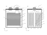
本実施形態の電池1につき図1及び図2を参照して説明する。図1(a)は、電池1の正面(XZ平面)からの透視概要図であり、図1(b)は、図1(a)のA−A´線のYZ平面における断面概要図である。なお、以下で使用する図は、いずれも同一の直交座標系を用いている。また、図1(a)は理解促進のための概要図であるため、図1(b)に示した各構成が全て記載されているわけではない。 The battery 1 of this embodiment will be described with reference to FIGS. 1 and 2. FIG. 1A is a perspective schematic view from the front (XZ plane) of the battery 1, and FIG. 1B is a schematic cross-sectional view in the YZ plane of the AA ′ line of FIG. . Note that the drawings used below all use the same orthogonal coordinate system. Moreover, since FIG. 1A is a schematic diagram for promoting understanding, not all the components shown in FIG. 1B are described.
まず、電池1は、XY平面上に略矩形の形状の底面をもち且つ当該略矩形の全ての辺からZ軸方向へ伸びる壁面をもつ角型の導電性(例えば、アルミニウム等の金属製)の容器本体2と、容器本体2に収納され且つ正極板7aと負極板12とがセパレータ16を介して積層された積層電極体17と、積層電極体17を容器本体2に収納後に容器本体2を密閉する蓋3とを備えている(容器本体2と蓋3とがレーザ溶接等で密閉されて「電池容器」となる)。なお、図示しないものの、電池容器には電解液又は電解質が蓄えられる。
ここで、蓋3は容器本体2と同一の導電性の材質である。そして、蓋3には、蓋3を貫通して配置される例えば円柱状の電極端子(正極端子4及び負極端子5)と、電極端子を蓋3に固定し且つ電極端子と蓋3との間を電気的に絶縁する絶縁性の樹脂6(例えば、プラスチック樹脂等の絶縁体)が形成されている。
First, the battery 1 is a rectangular conductive (for example, made of metal such as aluminum) having a substantially rectangular bottom surface on an XY plane and having wall surfaces extending in the Z-axis direction from all sides of the substantially rectangular shape. The container body 2, the laminated electrode body 17 that is housed in the container body 2, and the positive electrode plate 7 a and the negative electrode plate 12 are laminated via the
Here, the lid 3 is made of the same conductive material as that of the container body 2. The lid 3 has, for example, cylindrical electrode terminals (a positive terminal 4 and a negative terminal 5) disposed through the lid 3, and the electrode terminals are fixed to the lid 3 and between the electrode terminals and the lid 3. An insulating resin 6 (for example, an insulator such as plastic resin) is formed.
積層電極体17(ここでは、2つの積層電極体17aと17b)は、一例として、複数の正極板7と複数の負極板12とがセパレータ16を介して順次積層された積層型の積層電極体であるとして、以下説明する。
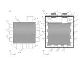
正極板7aは、アルミニウム等の正極用金属箔(以下、「正極基材」ともいう)の両面にマンガン酸リチウム等の正極活物質が塗工された後、打ち抜かれて形成される。正極板7は、正極基材に正極活物質が塗工されている略矩形の部分(以下、「正極塗工部」8という)と当該正極基材に正極活物質が塗工されていない略矩形の部分(以下、「正極非塗工部」9という)とを備えている。
正極塗工部8のX方向に長さを持つ2つの辺のうち、+Z方向にある辺に接続する略矩形の正極タブ10と、−Z方向にある辺に接続する略矩形の接触部11aは、正極非塗工部9である。
これら正極非塗工部9と正極塗工部8との接続関係は、図2(a)に示すとおりである。
すなわち、正極塗工部8は、X方向に寸法「W1」及びZ方向に寸法「W2」の略矩形である。また、正極非塗工部9の1つである正極タブ10は、X方向に寸法「W3」及びZ方向に寸法「W5」の略矩形であって、正極塗工部8のX方向の幅の中心からZ方向へ仮想線(以下、「正極仮想線」という)を引いた場合に、正極仮想線より+X方向に位置し且つ正極塗工部8のX方向内側に位置し且つ正極塗工部8に接続して一体となっている(従って、0<W3<{(W1)÷2}である)。さらに、正極非塗工部9の1つである接触部11aは、X方向に寸法「W1」及びZ方向に寸法「W4」の略矩形であって、正極塗工部8の上記−Z方向にある辺にX方向のズレなく接続して一体となっている。
なお、寸法「W5」は、正極端子4に電気的に接続するために十分な長さであり、寸法「W4」は、負極板12には電気的に接触しない範囲で電池容器に物理的に接触するために十分な長さである。
The laminated electrode body 17 (here, two laminated electrode bodies 17a and 17b) is, for example, a laminated type laminated electrode body in which a plurality of positive electrode plates 7 and a plurality of negative electrode plates 12 are sequentially laminated via a
The positive electrode plate 7a is formed by applying a positive electrode active material such as lithium manganate to both surfaces of a positive electrode metal foil (hereinafter also referred to as “positive electrode base material”) such as aluminum and then punching it. The positive electrode plate 7 includes a substantially rectangular portion (hereinafter, referred to as “positive electrode coating portion” 8) in which a positive electrode active material is applied to a positive electrode base material, and a positive electrode active material that is not applied to the positive electrode base material. And a rectangular portion (hereinafter referred to as “positive electrode non-coated portion” 9).
Of the two sides having a length in the X direction of the positive electrode coating portion 8, a substantially rectangular positive electrode tab 10 connected to a side in the + Z direction and a substantially rectangular contact portion 11a connected to a side in the -Z direction. Is a positive electrode non-coating portion 9.
The connection relationship between the positive electrode non-coating portion 9 and the positive electrode coating portion 8 is as shown in FIG.
That is, the positive electrode coating portion 8 has a substantially rectangular shape with a dimension “W1” in the X direction and a dimension “W2” in the Z direction. Further, the positive electrode tab 10 which is one of the positive electrode non-coated portions 9 has a substantially rectangular shape with a dimension “W3” in the X direction and a dimension “W5” in the Z direction, and the width of the positive electrode coated portion 8 in the X direction. When a virtual line (hereinafter referred to as “positive electrode virtual line”) is drawn in the Z direction from the center of the positive electrode, it is positioned in the + X direction from the positive electrode virtual line and inside the positive electrode coating portion 8 in the X direction and positive electrode coating. It is connected to the unit 8 and is integrated (therefore, 0 <W3 <{(W1) / 2)). Furthermore, the contact part 11a which is one of the positive electrode non-coating parts 9 is a substantially rectangular shape having a dimension “W1” in the X direction and a dimension “W4” in the Z direction, and is in the −Z direction of the positive electrode coating part 8. Are connected to the side without any deviation in the X direction.
Note that the dimension “W5” is long enough to be electrically connected to the positive electrode terminal 4, and the dimension “W4” is physically attached to the battery container within a range that does not electrically contact the negative electrode plate 12. It is long enough to make contact.
一方、負極板12は、銅等の負極用金属箔(以下、「負極基材」ともいう)の両面にカーボン等の負極活物質が塗工された後、打ち抜かれて形成される。負極板12は、負極基材に負極活物質が塗工されている略矩形の部分(以下、「負極塗工部」13という)と当該負極基材に負極活物質が塗工されていない略矩形の部分(以下、「負極非塗工部」14という)とを備えている。
負極塗工部13のX方向に長さを持つ2つの辺のうち、+Z方向にある辺に接続する略矩形の負極タブ15は、負極非塗工部14である。
これら負極非塗工部14と負極塗工部13との接続関係は、図2(b)に示すとおりである。
すなわち、負極塗工部13は、X方向に寸法「D1」及びZ方向に寸法「D2」の略矩形である。また、負極非塗工部14である負極タブ15は、X方向に寸法「D3」及びZ方向に寸法「D4」の略矩形であって、負極塗工部13のX方向の幅の中心からZ方向へ仮想線(以下、「負極仮想線」という)を引いた場合に、負極仮想線より−X方向に位置し且つ負極塗工部13のX方向内側に位置し且つ負極塗工部13に接続して一体となっている(従って、0<D3<{(D1)÷2}である)。
負極塗工部13のXZ平面における略矩形の寸法は、電池容器の内部に折れ曲がることなく収納される寸法、すなわち電池容器のXZ平面における内径より小さい。そして、負極塗工部13のXZ平面における略矩形の寸法は、正極塗工部8のXZ平面における略矩形の寸法よりも大きい。すなわち、0<W1<D1且つ0<W2<D2である。
従って、図1(a)に示すように、Y方向から見て、正極塗工部8は負極塗工部13の面内に配置される。また、負極タブ15は、正極仮想線と負極仮想線とをXZ平面上で実質的に合わせて正極板7aと負極板12とをセパレータを介して順次Y方向に積層するので、XZ平面上で正極タブ10と重ならない位置に配置される。
On the other hand, the negative electrode plate 12 is formed by coating a negative electrode active material such as carbon on both surfaces of a negative electrode metal foil such as copper (hereinafter also referred to as “negative electrode substrate”) and then punching it. The negative electrode plate 12 includes a substantially rectangular portion (hereinafter referred to as “negative electrode coating portion” 13) in which a negative electrode active material is coated on a negative electrode substrate, and a negative electrode substrate in which a negative electrode active material is not coated. And a rectangular portion (hereinafter referred to as “negative electrode non-coating portion” 14).
Of the two sides having a length in the X direction of the negative electrode coating part 13, the substantially rectangular
The connection relationship between the negative electrode non-coated portion 14 and the negative electrode coated portion 13 is as shown in FIG.
That is, the negative electrode coating portion 13 has a substantially rectangular shape with a dimension “D1” in the X direction and a dimension “D2” in the Z direction. Further, the
The dimension of the substantially rectangular shape in the XZ plane of the negative electrode coating portion 13 is smaller than the dimension in which the battery container is accommodated without being bent, that is, the inner diameter of the battery container in the XZ plane. And the substantially rectangular dimension in the XZ plane of the negative electrode coating part 13 is larger than the substantially rectangular dimension in the XZ plane of the positive electrode coating part 8. FIG. That is, 0 <W1 <D1 and 0 <W2 <D2.
Accordingly, as shown in FIG. 1A, the positive electrode coating portion 8 is disposed in the plane of the negative electrode coating portion 13 when viewed from the Y direction. Further, the
セパレータ16は、本実施形態では、図1(b)に示すように、袋状のセパレータとしている。ここでは、袋状のセパレータの内部に電極板の塗工部全面(ここでは、負極塗工部13の全面)が収められ且つ当該袋の内部から外部へ電極タブ(ここでは、負極タブ15)が飛び出している状態を「内包」という。
セパレータ16を袋状とすることで、正極電位に帯電する電池容器に負極板12が接触することが十分に防止され、また、負極板12が正極板7に接触することが十分に防止される。
もちろん、セパレータの寸法等を調整することで、かような防止の機能が達成できる場合には、必ずしも袋状である必要はない。従って、セパレータの形状を単に略矩形のシート状としてもよい。
In this embodiment, the
By making the
Of course, when such a prevention function can be achieved by adjusting the dimensions and the like of the separator, it is not always necessary to have a bag shape. Therefore, the shape of the separator may be simply a substantially rectangular sheet.
そして、袋状のセパレータ16に内包された負極板12から積層を始め、当該負極板12のセパレータ16の上(+Y方向)に正極板7aを積層し、次に、当該正極板7aの上(+Y方向)に袋状のセパレータ16に内包された負極板12を積層する。この際、積層される複数の負極板4は、各々の負極タブ15のXZ平面における位置を揃えて積層される。また、積層される複数の正極板7aは、各々の正極タブ10のXZ平面における位置を揃えて積層される。
これを順次繰り返し、最終的に複数の正極板7aと複数の負極板12からなり且つX方向から見たY方向の両端に負極板12が配置される積層電極体17が形成される。図1(b)では、2つの同一の積層電極体17(それぞれ番号を17aと17bとして図に示す)が電池容器に納められた例を示している。
なお、Y方向から見て実質的に同じ位置に揃えられた全ての正極タブ10は、リベット打ち又は溶接等で、正極端子4に電気的に接続される。この際、正極タブ10を直接的に正極端子4に接続してもよいし、正極タブ10と正極端子4との間に金属製の正極用リードを介在させてもよい。また、Y方向から見て実質的に同じ位置に揃えられた全ての負極タブ15は、リベット打ち又は溶接等で、負極端子5に電気的に接続される。この際、負極タブ15を直接的に負極端子5に接続してもよいし、負極タブ15と負極端子5との間に金属製の負極用リードを介在させてもよい。
Then, lamination is started from the negative electrode plate 12 included in the bag-
This is sequentially repeated, and finally, a laminated electrode body 17 is formed which includes a plurality of positive electrode plates 7a and a plurality of negative electrode plates 12 and in which the negative electrode plates 12 are disposed at both ends in the Y direction as viewed from the X direction. FIG. 1B shows an example in which two identical stacked electrode bodies 17 (respectively indicated by numbers 17a and 17b in the figure) are housed in a battery container.
Note that all the positive electrode tabs 10 aligned at substantially the same position as viewed from the Y direction are electrically connected to the positive electrode terminal 4 by riveting or welding. At this time, the positive electrode tab 10 may be directly connected to the positive electrode terminal 4, or a metal positive electrode lead may be interposed between the positive electrode tab 10 and the positive electrode terminal 4. Also, all the
以上の構成により、本実施形態の電池1においては、電池容器の内部に収納された積層電極体17の一部である正極板7aの接触部11aが、電池容器、具体的には容器本体2の底面に、重力によって接することとなる。図1(b)に示すように、接触部11aの先端を、袋状のセパレータ16と当該底とで挟み込む配置とすれば、接触部11aが当該底面に確実に接する構造とすることができる。
正極基材である接触部11aは熱伝導が良い金属であるので、このため、積層電極体17の内部で発生した熱を、電池容器まで素早く熱伝導させて放熱することができる。従って、結果として、電池の劣化を防止することができる。この際、特許文献1の放熱板のような、基本となる電池構成部材以外の部材を電池容器の内部に配置するのではなく、基本となる電池構成部材の1つである正極基材からなる接触部11aを用いているので、電極板等の寸法または枚数を減少させる必要がない。
また、導電性の電池容器の内部で正極板7aと電池容器とを電気的に接続し、電池容器を正極板7aと同じ電位、すなわち正極端子4と実質的に同じ電位とすることができるので、電池容器と電解液との反応を防止することができる。この際、接触部11aは正極板7aの一部であって、特許文献2のように電池容器の外部に配置される部材ではなく、また、積層電極体の重みで圧迫されて電池容器の底面に接触又は重力で当該底面に接触するので外れる恐れがなく、また、電池1の取り扱いも容易となる。
さらに、一般的に、導電性の電池容器を用いる場合には、積層電極体が電池容器に電気的に接続しないように、電池容器の内部と当該電池容器に収納される積層電極体との間に絶縁板または絶縁シートなどの絶縁部材が配置される。これは、積層電極体の正極板と負極板とが電気的に短絡しないようになされる処置である。しかしながら、電池1では、負極板12は袋状のセパレータ16に内包されているので、負極板12と正極板7aとは電気的に短絡せず、また、正極板7aはその接触部11aを電池容器の底面に接触させる構成であるので、そもそも当該絶縁部材が不要となる。もちろん、設計に応じて、当該底面にかつて配置していた絶縁部材のみを取り除き、電池容器の内壁のうち当該底面以外の他の壁面と積層電極体との間には依然として絶縁部材を配置してもよい。
従って、本実施形態の電池1は、電池性能を向上させるだけでなく、コスト削減にも寄与することができる。
With the above configuration, in the battery 1 of the present embodiment, the contact portion 11a of the positive electrode plate 7a, which is a part of the laminated electrode body 17 housed inside the battery container, is the battery container, specifically the container body 2. It will come into contact with the bottom of the surface by gravity. As shown in FIG. 1B, if the tip of the contact portion 11a is sandwiched between the bag-
Since the contact part 11a which is a positive electrode base material is a metal with good heat conduction, the heat generated inside the laminated electrode body 17 can be quickly conducted to the battery container and radiated. Therefore, as a result, deterioration of the battery can be prevented. At this time, a member other than the basic battery constituent member such as the heat dissipation plate of Patent Document 1 is not disposed inside the battery container, but is made of a positive electrode base material that is one of the basic battery constituent members. Since the contact portion 11a is used, there is no need to reduce the size or number of electrode plates or the like.
Further, since the positive electrode plate 7a and the battery container are electrically connected inside the conductive battery container, the battery container can be set to the same potential as the positive electrode plate 7a, that is, substantially the same potential as the positive electrode terminal 4. The reaction between the battery container and the electrolytic solution can be prevented. At this time, the contact portion 11a is a part of the positive electrode plate 7a and is not a member arranged outside the battery container as in Patent Document 2, and is pressed by the weight of the laminated electrode body to be pressed on the bottom surface of the battery container. Since it contacts the bottom surface by gravity or by gravity, there is no fear of detachment, and handling of the battery 1 is facilitated.
Further, in general, when a conductive battery container is used, a gap between the inside of the battery container and the laminated electrode body housed in the battery container is prevented so that the laminated electrode body is not electrically connected to the battery container. An insulating member such as an insulating plate or an insulating sheet is disposed on the surface. This is a measure to prevent the positive electrode plate and the negative electrode plate of the laminated electrode body from being electrically short-circuited. However, in the battery 1, since the negative electrode plate 12 is included in the bag-
Therefore, the battery 1 of the present embodiment can not only improve battery performance but also contribute to cost reduction.
以上の電池1においては、図2(a)に示すように、接触部11aは、正極塗工部8のX方向に長さを持つ2つの辺のうち、−Z方向にある辺に隙間なく接続している。しかしながら、接触部11の形状は、当該隙間のない構造でなくともよい。
図3(a)に、変形例として示す電池の正極板7bを、また、図3(b)に、変形例として示す電池の正極板7cを示す。これら変形例の電池は、電池1の正極板7aのみをこれら正極板7bまたは7cと入れ替えたものであるので、他の構成については上記電池1と同様であり、説明を省略する。
正極板7bは、接触部11aを正極仮想線付近でX方向に2分割し、X方向の幅を寸法「W1a」とする接触部11bと、X方向の幅を寸法「W1b」とする接触部11cの2つの部分とした構成である(具体的には、0<W1a+W1b<W1である)。そして、これら2つの部分は、正極仮想線付近に開口ができるように配置される。この構成により、接触部11aの場合に比べ、電極板の内部へ効果的に電解液を浸潤または循環させることができる。
また、正極板7cは、接触部11aをX方向に3分割し、X方向の幅を寸法「W1c」とする接触部11d、X方向の幅を寸法「W1d」とする接触部11e及びX方向の幅を寸法「W1e」とする接触部11fの3つの部分とした構成である(具体的には、0<W1c+W1d+W1e<W1である)。そして、これら3つの部分は、互いの間に開口ができるように配置される。この構成により、接触部11aの場合に比べ、電極板の内部へ効果的に電解液を浸潤または循環させることができる。また、このように3つの部分としたことで、図3(a)に示した上記2つの部分に分けた場合に比べて開口の数が増加するので、より効果的に電極板の内部へ電解液を浸潤または循環させることができる。
本変形例の電池は、上述した電池1の効果も奏することはもちろん、かように電極板の内部へ電解液を効果的に浸潤または循環させることもできるので、より電池性能を向上させることができる。
In the battery 1 described above, as shown in FIG. 2A, the contact portion 11 a has no gap on the side in the −Z direction among the two sides having a length in the X direction of the positive electrode coating portion 8. Connected. However, the shape of the contact portion 11 may not be a structure without the gap.
FIG. 3A shows a positive electrode plate 7b of a battery shown as a modification, and FIG. 3B shows a positive electrode plate 7c of the battery shown as a modification. Since the batteries of these modified examples are obtained by replacing only the positive electrode plate 7a of the battery 1 with these positive electrode plates 7b or 7c, the other configurations are the same as those of the battery 1, and description thereof is omitted.
The positive electrode plate 7b includes a contact portion 11b that divides the contact portion 11a in the X direction in the vicinity of the positive electrode imaginary line and has a width “W1a” in the X direction and a contact portion that has a width “W1b” in the X direction. 11c (specifically, 0 <W1a + W1b <W1). And these two parts are arrange | positioned so that opening may be made in the positive electrode virtual line vicinity. With this configuration, it is possible to effectively infiltrate or circulate the electrolyte into the electrode plate as compared with the case of the contact portion 11a.
Further, the positive electrode plate 7c is obtained by dividing the contact portion 11a into three in the X direction, the contact portion 11d having the width in the X direction as “W1c”, the contact portion 11e having the width in the X direction as “W1d”, and the X direction. The width of each of the contact portions 11f has a dimension “W1e” (specifically, 0 <W1c + W1d + W1e <W1). And these three parts are arrange | positioned so that an opening may be made between each other. With this configuration, it is possible to effectively infiltrate or circulate the electrolyte into the electrode plate as compared with the case of the contact portion 11a. In addition, since the number of openings is increased as compared with the case of dividing into the two parts shown in FIG. 3A by using three parts in this way, the electrolysis can be more effectively performed inside the electrode plate. Fluid can be infiltrated or circulated.
The battery of this modification can also improve the battery performance because it can effectively infiltrate or circulate the electrolyte into the electrode plate as well as the effects of the battery 1 described above. it can.
さらに、他の変形例の電池を図4(b)に示す。図4(b)の電池は、図4(a)に示すように、正極板7c(図3(b)参照)のZ方向に長さを持つ2辺のうち、−X方向の辺に、正極非塗工部9として接触部11d、11eおよび11fに相当する接触部11g、11hおよび11iが形成され、さらに+X方向の辺に、正極非塗工部9として接触部11d、11eおよび11fに相当する接触部11j、11kおよび11lが形成された正極板7dを用いている。この変形例の電池は、電池1の正極板7aのみを正極板7dと入れ替えたものであるので、他の構成については上記電池1と同様であり、説明を省略する。
正極板7dは、電池容器の底面に接触部11d、11eおよび11fが接触するのみならず、電池容器の側壁にも接触部11g、11h、11i、11j、11kおよび11lが接触するため、積層電極体17の内部で発生した熱を、図1の電池1に比べ、電池容器までより素早く熱伝導させて放熱することができる。また、接触部11g、11hおよび11i、接触部11j、11kおよび11lの間には開口が形成されるようこれら各接触部が配置されているので、電解液の循環も保たれる。
Furthermore, the battery of another modification is shown in FIG.4 (b). As shown in FIG. 4 (a), the battery of FIG. 4 (b) has two sides having a length in the Z direction of the positive electrode plate 7c (see FIG. 3 (b)) on the side in the −X direction. Contact portions 11g, 11h, and 11i corresponding to the contact portions 11d, 11e, and 11f are formed as the positive electrode non-coated portion 9, and are further formed on the contact portions 11d, 11e, and 11f as the positive electrode non-coated portion 9 on the side in the + X direction. A positive electrode plate 7d on which corresponding contact portions 11j, 11k, and 11l are formed is used. Since the battery of this modification is obtained by replacing only the positive electrode plate 7a of the battery 1 with the positive electrode plate 7d, the other configuration is the same as that of the battery 1, and the description thereof is omitted.
The positive electrode plate 7d has not only the contact portions 11d, 11e and 11f in contact with the bottom surface of the battery container, but also the contact portions 11g, 11h, 11i, 11j, 11k and 11l in contact with the side walls of the battery container. The heat generated inside the body 17 can be radiated by heat conduction to the battery container more quickly than the battery 1 of FIG. Further, since these contact portions are arranged so as to form openings between the contact portions 11g, 11h and 11i and the contact portions 11j, 11k and 11l, the circulation of the electrolytic solution is also maintained.
本発明は上述した実施形態やその変形例、またはこれらの組み合わせに限定されず、本発明の趣旨を逸脱しない限りで種々の変形が可能である。例えば、電池容器の形状は角型として説明したが、円筒型であってもよい。同様に、積層電極体17は、複数の正極板と複数の負極板とがそれぞれセパレータを介して順次積層された積層電極体(積層型積層電極体)でもよいし、1つの正極板と1つの負極板とが1つのセパレータを介して積層され且つ巻かれた状態の積層電極体(捲回型積層電極体)でもよい。なお、積層電極体6が積層型積層電極体である場合には、正極板7と負極板12の数は1以上、すなわち適宜複数に設計が可能である。
また、上述した実施形態やその変形例では、接触部11は正極基材としたが、接触部11を正極基板とは別個に形成した後に、正極基材へ溶接等して接続してもよい。
さらに、上述した実施形態やその変形例では、接触部11は正極タブ10とは別に形成したが、これらを一体として、正極タブ10に接触部11の機能を持たせてもよい。
その上、実施形態およびその変形例では、電池容器を正極電位にすべく接触部11が正極板7に配置されているが、電池の材料(活物質、電解液等)に応じて、電池容器を負極電位にすべく接触部11に相当する構成を負極板12に配置してもよい。その場合には、電池1で説明した正極板7に相当する説明を負極板12に相当する説明と入れ替えれば、電池構成が容易に理解される。
The present invention is not limited to the above-described embodiment, its modifications, or a combination thereof, and various modifications can be made without departing from the spirit of the present invention. For example, although the shape of the battery container has been described as a square shape, it may be a cylindrical shape. Similarly, the laminated electrode body 17 may be a laminated electrode body in which a plurality of positive electrode plates and a plurality of negative electrode plates are sequentially laminated via separators, respectively, or one positive electrode plate and one negative electrode plate. A laminated electrode body (rolled laminated electrode body) in a state where the negative electrode plate is laminated and wound via one separator may be used. When the laminated electrode body 6 is a laminated type laminated electrode body, the number of the positive electrode plates 7 and the negative electrode plates 12 can be designed to be 1 or more, that is, appropriately plural.
In the above-described embodiment and its modifications, the contact portion 11 is a positive electrode base material. However, after the contact portion 11 is formed separately from the positive electrode substrate, it may be connected to the positive electrode base material by welding or the like. .
Furthermore, although the contact part 11 was formed separately from the positive electrode tab 10 in embodiment mentioned above and its modification, you may give the function of the contact part 11 to the positive electrode tab 10 by uniting these.
In addition, in the embodiment and its modification, the contact portion 11 is disposed on the positive electrode plate 7 so as to bring the battery container to the positive electrode potential. However, depending on the battery material (active material, electrolyte, etc.), the battery container A structure corresponding to the contact portion 11 may be disposed on the negative electrode plate 12 so as to have a negative electrode potential. In that case, the battery configuration can be easily understood by replacing the description corresponding to the positive electrode plate 7 described in the battery 1 with the description corresponding to the negative electrode plate 12.
1…電池、2…容器本体、3…蓋、4…正極端子、5…負極端子、6…樹脂、
7(7a、7b、7c、7d)…正極板、8…正極塗工部、9…正極非塗工部、
10…正極タブ、11(11a 〜 11l)…接触部、
12…負極板、13…負極塗工部、14…負極非塗工部、15…負極タブ、
16…セパレータ、17(17a、17b)…積層電極体
DESCRIPTION OF SYMBOLS 1 ... Battery, 2 ... Container main body, 3 ... Cover, 4 ... Positive electrode terminal, 5 ... Negative electrode terminal, 6 ... Resin,
7 (7a, 7b, 7c, 7d) ... positive electrode plate, 8 ... positive electrode coating part, 9 ... positive electrode non-coating part,
10 ... Positive electrode tab, 11 (11a to 11l) ... Contact part,
12 ... Negative electrode plate, 13 ... Negative electrode coating part, 14 ... Negative electrode non-coating part, 15 ... Negative electrode tab,
16 ... Separator, 17 (17a, 17b) ... Laminated electrode body
Claims (7)
接触部を備え第2極性の電位の第2電極板と、
前記第1電極板と前記第2電極板との間に配置されたセパレータと、
前記第1電極板と前記第2電極板と前記セパレータとを収納した導電性の電池容器と
を有し、
前記接触部は前記電池容器に接触することを特徴とする電池。 A first electrode plate having a first polarity potential;
A second electrode plate having a contact portion and having a second polarity potential;
A separator disposed between the first electrode plate and the second electrode plate;
A conductive battery container containing the first electrode plate, the second electrode plate, and the separator;
The battery, wherein the contact portion contacts the battery container.
前記第1電極板が前記第1電極端子に電気的に接続され、前記第2電極板が前記第2電極端子に電気的に接続され、前記接触部は前記容器本体に接触することを特徴とする請求項1に記載の電池。 The battery container includes a lid in which a first electrode terminal and a second electrode terminal are disposed via an insulator, and a container body,
The first electrode plate is electrically connected to the first electrode terminal, the second electrode plate is electrically connected to the second electrode terminal, and the contact portion is in contact with the container body. The battery according to claim 1.
前記接触部は前記非塗工部であることを特徴とする請求項2に記載の電池。 The second electrode plate includes a coated portion in which an electrode active material is coated on a base material, and a non-coated portion in which the electrode active material is not coated on the base material,
The battery according to claim 2, wherein the contact portion is the non-coated portion.
The first polarity is a positive electrode, the first electrode plate is a positive electrode plate, the second polarity is a negative electrode, and the second electrode plate is a negative electrode plate. The battery according to any one of 5.
Priority Applications (3)
| Application Number | Priority Date | Filing Date | Title |
|---|---|---|---|
| JP2011146525A JP2013016275A (en) | 2011-06-30 | 2011-06-30 | Battery |
| CN2012203085277U CN202797184U (en) | 2011-06-30 | 2012-06-27 | Battery |
| US13/535,692 US20130004825A1 (en) | 2011-06-30 | 2012-06-28 | Battery |
Applications Claiming Priority (1)
| Application Number | Priority Date | Filing Date | Title |
|---|---|---|---|
| JP2011146525A JP2013016275A (en) | 2011-06-30 | 2011-06-30 | Battery |
Publications (1)
| Publication Number | Publication Date |
|---|---|
| JP2013016275A true JP2013016275A (en) | 2013-01-24 |
Family
ID=47390994
Family Applications (1)
| Application Number | Title | Priority Date | Filing Date |
|---|---|---|---|
| JP2011146525A Pending JP2013016275A (en) | 2011-06-30 | 2011-06-30 | Battery |
Country Status (3)
| Country | Link |
|---|---|
| US (1) | US20130004825A1 (en) |
| JP (1) | JP2013016275A (en) |
| CN (1) | CN202797184U (en) |
Cited By (2)
| Publication number | Priority date | Publication date | Assignee | Title |
|---|---|---|---|---|
| JP2018156901A (en) * | 2017-03-21 | 2018-10-04 | 株式会社東芝 | Secondary battery, battery pack and vehicle |
| US11600025B2 (en) | 2019-03-29 | 2023-03-07 | Canon Kabushiki Kaisha | Image processing method, image processing apparatus, image processing system, and learnt model manufacturing method |
Families Citing this family (2)
| Publication number | Priority date | Publication date | Assignee | Title |
|---|---|---|---|---|
| KR102283630B1 (en) * | 2013-11-28 | 2021-08-02 | 가부시키가이샤 한도오따이 에네루기 켄큐쇼 | Power storage unit and electronic device including the same |
| KR102487890B1 (en) * | 2015-08-25 | 2023-01-12 | 삼성에스디아이 주식회사 | Secondary battery |
Citations (3)
| Publication number | Priority date | Publication date | Assignee | Title |
|---|---|---|---|---|
| JPS63136474A (en) * | 1986-11-27 | 1988-06-08 | Toshiba Battery Co Ltd | Enclosed type alkaline storage battery |
| JPH11144771A (en) * | 1997-11-11 | 1999-05-28 | Japan Storage Battery Co Ltd | Heat radiator of battery |
| JP2003168422A (en) * | 2001-11-30 | 2003-06-13 | Sanyo Electric Co Ltd | Square-shaped alkaline storage battery |
-
2011
- 2011-06-30 JP JP2011146525A patent/JP2013016275A/en active Pending
-
2012
- 2012-06-27 CN CN2012203085277U patent/CN202797184U/en not_active Expired - Fee Related
- 2012-06-28 US US13/535,692 patent/US20130004825A1/en not_active Abandoned
Patent Citations (3)
| Publication number | Priority date | Publication date | Assignee | Title |
|---|---|---|---|---|
| JPS63136474A (en) * | 1986-11-27 | 1988-06-08 | Toshiba Battery Co Ltd | Enclosed type alkaline storage battery |
| JPH11144771A (en) * | 1997-11-11 | 1999-05-28 | Japan Storage Battery Co Ltd | Heat radiator of battery |
| JP2003168422A (en) * | 2001-11-30 | 2003-06-13 | Sanyo Electric Co Ltd | Square-shaped alkaline storage battery |
Cited By (2)
| Publication number | Priority date | Publication date | Assignee | Title |
|---|---|---|---|---|
| JP2018156901A (en) * | 2017-03-21 | 2018-10-04 | 株式会社東芝 | Secondary battery, battery pack and vehicle |
| US11600025B2 (en) | 2019-03-29 | 2023-03-07 | Canon Kabushiki Kaisha | Image processing method, image processing apparatus, image processing system, and learnt model manufacturing method |
Also Published As
| Publication number | Publication date |
|---|---|
| CN202797184U (en) | 2013-03-13 |
| US20130004825A1 (en) | 2013-01-03 |
Similar Documents
| Publication | Publication Date | Title |
|---|---|---|
| JP6496455B2 (en) | Battery module and battery pack including the same | |
| KR101689750B1 (en) | Battery pack | |
| EP3010072A1 (en) | Battery pack | |
| KR102059077B1 (en) | Battery module, battery pack comprising the battery module and vehicle comprising the battery pack | |
| CN105990598B (en) | Electric storage element | |
| EP3007246B1 (en) | Rechargeable battery | |
| JP5314665B2 (en) | battery | |
| JP2019518313A (en) | Battery module, battery pack including the same, and automobile including the battery pack | |
| KR20130133585A (en) | Pouch type secondary battery | |
| JP6120996B2 (en) | Base plate for battery module assembly with new structure | |
| JP2020528654A (en) | Battery module and battery pack with it | |
| JP2012190588A (en) | Secondary battery | |
| US20130266845A1 (en) | Battery | |
| KR20130016746A (en) | Secondary battery | |
| JP2015141798A (en) | power storage device | |
| JP2013161790A (en) | Secondary battery | |
| KR20140072689A (en) | Battery Module Assembly | |
| JP2013125657A (en) | Battery | |
| JP2013016275A (en) | Battery | |
| KR101669123B1 (en) | Pouch type secondary battery and battery module including the same | |
| JP2013037996A (en) | Battery | |
| JP7027630B2 (en) | Secondary battery and battery pack containing it | |
| KR20150046533A (en) | Pouch type secondary battery and battery pack including the same | |
| JP2023542479A (en) | Battery cells, batteries, and devices that use battery cells as a power source | |
| JP7027636B2 (en) | Terminal case with improved secondary battery status estimation function |
Legal Events
| Date | Code | Title | Description |
|---|---|---|---|
| A977 | Report on retrieval |
Free format text: JAPANESE INTERMEDIATE CODE: A971007 Effective date: 20130416 |
|
| A131 | Notification of reasons for refusal |
Free format text: JAPANESE INTERMEDIATE CODE: A131 Effective date: 20130514 |
|
| RD03 | Notification of appointment of power of attorney |
Free format text: JAPANESE INTERMEDIATE CODE: A7423 Effective date: 20130708 |
|
| A521 | Request for written amendment filed |
Free format text: JAPANESE INTERMEDIATE CODE: A821 Effective date: 20130709 |
|
| A02 | Decision of refusal |
Free format text: JAPANESE INTERMEDIATE CODE: A02 Effective date: 20130924 |