JP6986827B2 - Power storage device and electronic equipment - Google Patents
Power storage device and electronic equipment Download PDFInfo
- Publication number
- JP6986827B2 JP6986827B2 JP2016019260A JP2016019260A JP6986827B2 JP 6986827 B2 JP6986827 B2 JP 6986827B2 JP 2016019260 A JP2016019260 A JP 2016019260A JP 2016019260 A JP2016019260 A JP 2016019260A JP 6986827 B2 JP6986827 B2 JP 6986827B2
- Authority
- JP
- Japan
- Prior art keywords
- electrode
- negative electrode
- positive electrode
- region
- current collector
- Prior art date
- Legal status (The legal status is an assumption and is not a legal conclusion. Google has not performed a legal analysis and makes no representation as to the accuracy of the status listed.)
- Active
Links
Images


Classifications
-
- H—ELECTRICITY
- H01—ELECTRIC ELEMENTS
- H01M—PROCESSES OR MEANS, e.g. BATTERIES, FOR THE DIRECT CONVERSION OF CHEMICAL ENERGY INTO ELECTRICAL ENERGY
- H01M4/00—Electrodes
- H01M4/02—Electrodes composed of, or comprising, active material
- H01M4/64—Carriers or collectors
- H01M4/70—Carriers or collectors characterised by shape or form
- H01M4/72—Grids
-
- H—ELECTRICITY
- H01—ELECTRIC ELEMENTS
- H01G—CAPACITORS; CAPACITORS, RECTIFIERS, DETECTORS, SWITCHING DEVICES OR LIGHT-SENSITIVE DEVICES, OF THE ELECTROLYTIC TYPE
- H01G11/00—Hybrid capacitors, i.e. capacitors having different positive and negative electrodes; Electric double-layer [EDL] capacitors; Processes for the manufacture thereof or of parts thereof
- H01G11/22—Electrodes
- H01G11/26—Electrodes characterised by their structure, e.g. multi-layered, porosity or surface features
-
- H—ELECTRICITY
- H01—ELECTRIC ELEMENTS
- H01G—CAPACITORS; CAPACITORS, RECTIFIERS, DETECTORS, SWITCHING DEVICES OR LIGHT-SENSITIVE DEVICES, OF THE ELECTROLYTIC TYPE
- H01G11/00—Hybrid capacitors, i.e. capacitors having different positive and negative electrodes; Electric double-layer [EDL] capacitors; Processes for the manufacture thereof or of parts thereof
- H01G11/66—Current collectors
- H01G11/70—Current collectors characterised by their structure
-
- H—ELECTRICITY
- H01—ELECTRIC ELEMENTS
- H01G—CAPACITORS; CAPACITORS, RECTIFIERS, DETECTORS, SWITCHING DEVICES OR LIGHT-SENSITIVE DEVICES, OF THE ELECTROLYTIC TYPE
- H01G11/00—Hybrid capacitors, i.e. capacitors having different positive and negative electrodes; Electric double-layer [EDL] capacitors; Processes for the manufacture thereof or of parts thereof
- H01G11/66—Current collectors
- H01G11/72—Current collectors specially adapted for integration in multiple or stacked hybrid or EDL capacitors
-
- H—ELECTRICITY
- H01—ELECTRIC ELEMENTS
- H01G—CAPACITORS; CAPACITORS, RECTIFIERS, DETECTORS, SWITCHING DEVICES OR LIGHT-SENSITIVE DEVICES, OF THE ELECTROLYTIC TYPE
- H01G11/00—Hybrid capacitors, i.e. capacitors having different positive and negative electrodes; Electric double-layer [EDL] capacitors; Processes for the manufacture thereof or of parts thereof
- H01G11/74—Terminals, e.g. extensions of current collectors
- H01G11/76—Terminals, e.g. extensions of current collectors specially adapted for integration in multiple or stacked hybrid or EDL capacitors
-
- H—ELECTRICITY
- H01—ELECTRIC ELEMENTS
- H01G—CAPACITORS; CAPACITORS, RECTIFIERS, DETECTORS, SWITCHING DEVICES OR LIGHT-SENSITIVE DEVICES, OF THE ELECTROLYTIC TYPE
- H01G11/00—Hybrid capacitors, i.e. capacitors having different positive and negative electrodes; Electric double-layer [EDL] capacitors; Processes for the manufacture thereof or of parts thereof
- H01G11/78—Cases; Housings; Encapsulations; Mountings
- H01G11/82—Fixing or assembling a capacitive element in a housing, e.g. mounting electrodes, current collectors or terminals in containers or encapsulations
-
- H—ELECTRICITY
- H01—ELECTRIC ELEMENTS
- H01G—CAPACITORS; CAPACITORS, RECTIFIERS, DETECTORS, SWITCHING DEVICES OR LIGHT-SENSITIVE DEVICES, OF THE ELECTROLYTIC TYPE
- H01G11/00—Hybrid capacitors, i.e. capacitors having different positive and negative electrodes; Electric double-layer [EDL] capacitors; Processes for the manufacture thereof or of parts thereof
- H01G11/84—Processes for the manufacture of hybrid or EDL capacitors, or components thereof
- H01G11/86—Processes for the manufacture of hybrid or EDL capacitors, or components thereof specially adapted for electrodes
-
- H—ELECTRICITY
- H01—ELECTRIC ELEMENTS
- H01M—PROCESSES OR MEANS, e.g. BATTERIES, FOR THE DIRECT CONVERSION OF CHEMICAL ENERGY INTO ELECTRICAL ENERGY
- H01M10/00—Secondary cells; Manufacture thereof
- H01M10/04—Construction or manufacture in general
- H01M10/045—Cells or batteries with folded plate-like electrodes
-
- H—ELECTRICITY
- H01—ELECTRIC ELEMENTS
- H01M—PROCESSES OR MEANS, e.g. BATTERIES, FOR THE DIRECT CONVERSION OF CHEMICAL ENERGY INTO ELECTRICAL ENERGY
- H01M10/00—Secondary cells; Manufacture thereof
- H01M10/04—Construction or manufacture in general
- H01M10/0459—Cells or batteries with folded separator between plate-like electrodes
-
- H—ELECTRICITY
- H01—ELECTRIC ELEMENTS
- H01M—PROCESSES OR MEANS, e.g. BATTERIES, FOR THE DIRECT CONVERSION OF CHEMICAL ENERGY INTO ELECTRICAL ENERGY
- H01M10/00—Secondary cells; Manufacture thereof
- H01M10/05—Accumulators with non-aqueous electrolyte
- H01M10/058—Construction or manufacture
- H01M10/0587—Construction or manufacture of accumulators having only wound construction elements, i.e. wound positive electrodes, wound negative electrodes and wound separators
-
- H—ELECTRICITY
- H01—ELECTRIC ELEMENTS
- H01M—PROCESSES OR MEANS, e.g. BATTERIES, FOR THE DIRECT CONVERSION OF CHEMICAL ENERGY INTO ELECTRICAL ENERGY
- H01M4/00—Electrodes
- H01M4/02—Electrodes composed of, or comprising, active material
- H01M4/04—Processes of manufacture in general
-
- H—ELECTRICITY
- H01—ELECTRIC ELEMENTS
- H01M—PROCESSES OR MEANS, e.g. BATTERIES, FOR THE DIRECT CONVERSION OF CHEMICAL ENERGY INTO ELECTRICAL ENERGY
- H01M4/00—Electrodes
- H01M4/02—Electrodes composed of, or comprising, active material
- H01M4/64—Carriers or collectors
- H01M4/70—Carriers or collectors characterised by shape or form
- H01M4/76—Containers for holding the active material, e.g. tubes, capsules
-
- H—ELECTRICITY
- H01—ELECTRIC ELEMENTS
- H01M—PROCESSES OR MEANS, e.g. BATTERIES, FOR THE DIRECT CONVERSION OF CHEMICAL ENERGY INTO ELECTRICAL ENERGY
- H01M50/00—Constructional details or processes of manufacture of the non-active parts of electrochemical cells other than fuel cells, e.g. hybrid cells
- H01M50/10—Primary casings, jackets or wrappings of a single cell or a single battery
- H01M50/102—Primary casings, jackets or wrappings of a single cell or a single battery characterised by their shape or physical structure
- H01M50/105—Pouches or flexible bags
-
- H—ELECTRICITY
- H01—ELECTRIC ELEMENTS
- H01M—PROCESSES OR MEANS, e.g. BATTERIES, FOR THE DIRECT CONVERSION OF CHEMICAL ENERGY INTO ELECTRICAL ENERGY
- H01M50/00—Constructional details or processes of manufacture of the non-active parts of electrochemical cells other than fuel cells, e.g. hybrid cells
- H01M50/10—Primary casings, jackets or wrappings of a single cell or a single battery
- H01M50/116—Primary casings, jackets or wrappings of a single cell or a single battery characterised by the material
- H01M50/117—Inorganic material
- H01M50/119—Metals
-
- H—ELECTRICITY
- H01—ELECTRIC ELEMENTS
- H01M—PROCESSES OR MEANS, e.g. BATTERIES, FOR THE DIRECT CONVERSION OF CHEMICAL ENERGY INTO ELECTRICAL ENERGY
- H01M50/00—Constructional details or processes of manufacture of the non-active parts of electrochemical cells other than fuel cells, e.g. hybrid cells
- H01M50/10—Primary casings, jackets or wrappings of a single cell or a single battery
- H01M50/116—Primary casings, jackets or wrappings of a single cell or a single battery characterised by the material
- H01M50/121—Organic material
-
- H—ELECTRICITY
- H01—ELECTRIC ELEMENTS
- H01M—PROCESSES OR MEANS, e.g. BATTERIES, FOR THE DIRECT CONVERSION OF CHEMICAL ENERGY INTO ELECTRICAL ENERGY
- H01M50/00—Constructional details or processes of manufacture of the non-active parts of electrochemical cells other than fuel cells, e.g. hybrid cells
- H01M50/10—Primary casings, jackets or wrappings of a single cell or a single battery
- H01M50/116—Primary casings, jackets or wrappings of a single cell or a single battery characterised by the material
- H01M50/124—Primary casings, jackets or wrappings of a single cell or a single battery characterised by the material having a layered structure
- H01M50/126—Primary casings, jackets or wrappings of a single cell or a single battery characterised by the material having a layered structure comprising three or more layers
-
- H—ELECTRICITY
- H01—ELECTRIC ELEMENTS
- H01M—PROCESSES OR MEANS, e.g. BATTERIES, FOR THE DIRECT CONVERSION OF CHEMICAL ENERGY INTO ELECTRICAL ENERGY
- H01M50/00—Constructional details or processes of manufacture of the non-active parts of electrochemical cells other than fuel cells, e.g. hybrid cells
- H01M50/50—Current conducting connections for cells or batteries
- H01M50/531—Electrode connections inside a battery casing
- H01M50/533—Electrode connections inside a battery casing characterised by the shape of the leads or tabs
-
- H—ELECTRICITY
- H01—ELECTRIC ELEMENTS
- H01M—PROCESSES OR MEANS, e.g. BATTERIES, FOR THE DIRECT CONVERSION OF CHEMICAL ENERGY INTO ELECTRICAL ENERGY
- H01M50/00—Constructional details or processes of manufacture of the non-active parts of electrochemical cells other than fuel cells, e.g. hybrid cells
- H01M50/50—Current conducting connections for cells or batteries
- H01M50/543—Terminals
- H01M50/547—Terminals characterised by the disposition of the terminals on the cells
- H01M50/548—Terminals characterised by the disposition of the terminals on the cells on opposite sides of the cell
-
- H—ELECTRICITY
- H01—ELECTRIC ELEMENTS
- H01M—PROCESSES OR MEANS, e.g. BATTERIES, FOR THE DIRECT CONVERSION OF CHEMICAL ENERGY INTO ELECTRICAL ENERGY
- H01M50/00—Constructional details or processes of manufacture of the non-active parts of electrochemical cells other than fuel cells, e.g. hybrid cells
- H01M50/50—Current conducting connections for cells or batteries
- H01M50/543—Terminals
- H01M50/547—Terminals characterised by the disposition of the terminals on the cells
- H01M50/55—Terminals characterised by the disposition of the terminals on the cells on the same side of the cell
-
- H—ELECTRICITY
- H01—ELECTRIC ELEMENTS
- H01M—PROCESSES OR MEANS, e.g. BATTERIES, FOR THE DIRECT CONVERSION OF CHEMICAL ENERGY INTO ELECTRICAL ENERGY
- H01M50/00—Constructional details or processes of manufacture of the non-active parts of electrochemical cells other than fuel cells, e.g. hybrid cells
- H01M50/50—Current conducting connections for cells or batteries
- H01M50/543—Terminals
- H01M50/552—Terminals characterised by their shape
- H01M50/553—Terminals adapted for prismatic, pouch or rectangular cells
-
- H—ELECTRICITY
- H01—ELECTRIC ELEMENTS
- H01M—PROCESSES OR MEANS, e.g. BATTERIES, FOR THE DIRECT CONVERSION OF CHEMICAL ENERGY INTO ELECTRICAL ENERGY
- H01M50/00—Constructional details or processes of manufacture of the non-active parts of electrochemical cells other than fuel cells, e.g. hybrid cells
- H01M50/50—Current conducting connections for cells or batteries
- H01M50/543—Terminals
- H01M50/564—Terminals characterised by their manufacturing process
- H01M50/566—Terminals characterised by their manufacturing process by welding, soldering or brazing
-
- H—ELECTRICITY
- H01—ELECTRIC ELEMENTS
- H01G—CAPACITORS; CAPACITORS, RECTIFIERS, DETECTORS, SWITCHING DEVICES OR LIGHT-SENSITIVE DEVICES, OF THE ELECTROLYTIC TYPE
- H01G11/00—Hybrid capacitors, i.e. capacitors having different positive and negative electrodes; Electric double-layer [EDL] capacitors; Processes for the manufacture thereof or of parts thereof
- H01G11/54—Electrolytes
- H01G11/56—Solid electrolytes, e.g. gels; Additives therein
-
- H—ELECTRICITY
- H01—ELECTRIC ELEMENTS
- H01M—PROCESSES OR MEANS, e.g. BATTERIES, FOR THE DIRECT CONVERSION OF CHEMICAL ENERGY INTO ELECTRICAL ENERGY
- H01M10/00—Secondary cells; Manufacture thereof
- H01M10/05—Accumulators with non-aqueous electrolyte
- H01M10/052—Li-accumulators
- H01M10/0525—Rocking-chair batteries, i.e. batteries with lithium insertion or intercalation in both electrodes; Lithium-ion batteries
-
- H—ELECTRICITY
- H01—ELECTRIC ELEMENTS
- H01M—PROCESSES OR MEANS, e.g. BATTERIES, FOR THE DIRECT CONVERSION OF CHEMICAL ENERGY INTO ELECTRICAL ENERGY
- H01M10/00—Secondary cells; Manufacture thereof
- H01M10/05—Accumulators with non-aqueous electrolyte
- H01M10/056—Accumulators with non-aqueous electrolyte characterised by the materials used as electrolytes, e.g. mixed inorganic/organic electrolytes
- H01M10/0564—Accumulators with non-aqueous electrolyte characterised by the materials used as electrolytes, e.g. mixed inorganic/organic electrolytes the electrolyte being constituted of organic materials only
- H01M10/0565—Polymeric materials, e.g. gel-type or solid-type
-
- H—ELECTRICITY
- H01—ELECTRIC ELEMENTS
- H01M—PROCESSES OR MEANS, e.g. BATTERIES, FOR THE DIRECT CONVERSION OF CHEMICAL ENERGY INTO ELECTRICAL ENERGY
- H01M2220/00—Batteries for particular applications
- H01M2220/20—Batteries in motive systems, e.g. vehicle, ship, plane
-
- H—ELECTRICITY
- H01—ELECTRIC ELEMENTS
- H01M—PROCESSES OR MEANS, e.g. BATTERIES, FOR THE DIRECT CONVERSION OF CHEMICAL ENERGY INTO ELECTRICAL ENERGY
- H01M2220/00—Batteries for particular applications
- H01M2220/30—Batteries in portable systems, e.g. mobile phone, laptop
-
- H—ELECTRICITY
- H01—ELECTRIC ELEMENTS
- H01M—PROCESSES OR MEANS, e.g. BATTERIES, FOR THE DIRECT CONVERSION OF CHEMICAL ENERGY INTO ELECTRICAL ENERGY
- H01M2300/00—Electrolytes
- H01M2300/0085—Immobilising or gelification of electrolyte
-
- Y—GENERAL TAGGING OF NEW TECHNOLOGICAL DEVELOPMENTS; GENERAL TAGGING OF CROSS-SECTIONAL TECHNOLOGIES SPANNING OVER SEVERAL SECTIONS OF THE IPC; TECHNICAL SUBJECTS COVERED BY FORMER USPC CROSS-REFERENCE ART COLLECTIONS [XRACs] AND DIGESTS
- Y02—TECHNOLOGIES OR APPLICATIONS FOR MITIGATION OR ADAPTATION AGAINST CLIMATE CHANGE
- Y02E—REDUCTION OF GREENHOUSE GAS [GHG] EMISSIONS, RELATED TO ENERGY GENERATION, TRANSMISSION OR DISTRIBUTION
- Y02E60/00—Enabling technologies; Technologies with a potential or indirect contribution to GHG emissions mitigation
- Y02E60/10—Energy storage using batteries
-
- Y—GENERAL TAGGING OF NEW TECHNOLOGICAL DEVELOPMENTS; GENERAL TAGGING OF CROSS-SECTIONAL TECHNOLOGIES SPANNING OVER SEVERAL SECTIONS OF THE IPC; TECHNICAL SUBJECTS COVERED BY FORMER USPC CROSS-REFERENCE ART COLLECTIONS [XRACs] AND DIGESTS
- Y02—TECHNOLOGIES OR APPLICATIONS FOR MITIGATION OR ADAPTATION AGAINST CLIMATE CHANGE
- Y02E—REDUCTION OF GREENHOUSE GAS [GHG] EMISSIONS, RELATED TO ENERGY GENERATION, TRANSMISSION OR DISTRIBUTION
- Y02E60/00—Enabling technologies; Technologies with a potential or indirect contribution to GHG emissions mitigation
- Y02E60/13—Energy storage using capacitors
-
- Y—GENERAL TAGGING OF NEW TECHNOLOGICAL DEVELOPMENTS; GENERAL TAGGING OF CROSS-SECTIONAL TECHNOLOGIES SPANNING OVER SEVERAL SECTIONS OF THE IPC; TECHNICAL SUBJECTS COVERED BY FORMER USPC CROSS-REFERENCE ART COLLECTIONS [XRACs] AND DIGESTS
- Y02—TECHNOLOGIES OR APPLICATIONS FOR MITIGATION OR ADAPTATION AGAINST CLIMATE CHANGE
- Y02P—CLIMATE CHANGE MITIGATION TECHNOLOGIES IN THE PRODUCTION OR PROCESSING OF GOODS
- Y02P70/00—Climate change mitigation technologies in the production process for final industrial or consumer products
- Y02P70/50—Manufacturing or production processes characterised by the final manufactured product
Description
本発明の一態様は、蓄電装置及び電子機器に関する。 One aspect of the present invention relates to a power storage device and an electronic device.
なお、本発明の一態様は、上記の技術分野に限定されない。本明細書等で開示する発明の一態様は、物、方法、又は製造方法に関する。本発明の一態様は、プロセス、マシン、マニュファクチャ、又は組成物(コンポジション・オブ・マター)に関する。そのため、より具体的に本明細書で開示する本発明の一態様の技術分野としては、半導体装置、表示装置、発光装置、蓄電装置、記憶装置、それらの駆動方法、又は、それらの製造方法を一例として挙げることができる。 It should be noted that one aspect of the present invention is not limited to the above technical fields. One aspect of the invention disclosed in the present specification and the like relates to a product, a method, or a manufacturing method. One aspect of the invention relates to a process, machine, manufacture, or composition (composition of matter). Therefore, more specifically, as the technical field of one aspect of the present invention disclosed in the present specification, a semiconductor device, a display device, a light emitting device, a power storage device, a storage device, a driving method thereof, or a manufacturing method thereof is used. It can be given as an example.
なお、本明細書において電子機器とは、電気によって駆動する装置全般を指し、電気光学装置、および情報端末装置などは全て電子機器である。電子機器は蓄電装置を内蔵する場合がある。なお、ここで内蔵という定義は、取り外して交換できないように内蔵することは言うまでもなく、バッテリーパックなどとして自由に取り外しできるものも内蔵と呼ぶ。 In the present specification, the electronic device refers to all devices driven by electricity, and the electro-optical device, the information terminal device, and the like are all electronic devices. Electronic devices may have a built-in power storage device. It goes without saying that the definition of built-in is built-in so that it cannot be removed and replaced, and a battery pack or the like that can be freely removed is also called built-in.
近年、リチウムイオン二次電池、リチウムイオンキャパシタ、空気電池等、種々の蓄電装置の開発が盛んに行われている。特に高出力、高エネルギー密度であるリチウムイオン二次電池は、携帯電話やスマートフォン、ノート型コンピュータ等の携帯情報端末、携帯音楽プレーヤ、デジタルカメラ等の電子機器、あるいは医療機器、ハイブリッド車(HEV)、電気自動車(EV)、燃料電池自動車、またはプラグインハイブリッド車(PHEV)等の次世代クリーンエネルギー自動車など、半導体産業の発展と併せて急速にその需要が拡大し、充電可能なエネルギーの供給源として現代の情報化社会に不可欠なものとなっている。 In recent years, various power storage devices such as lithium ion secondary batteries, lithium ion capacitors, and air batteries have been actively developed. Lithium-ion secondary batteries, which have particularly high output and high energy density, are mobile information terminals such as mobile phones, smartphones, and notebook computers, electronic devices such as portable music players and digital cameras, medical devices, and hybrid vehicles (HEVs). , Electric vehicles (EV), fuel cell vehicles, or next-generation clean energy vehicles such as plug-in hybrid vehicles (PHEV), the demand for which is rapidly expanding with the development of the semiconductor industry, and a source of rechargeable energy. It has become indispensable to the modern computerized society.
一方、使用者が体に身につけて使用するウェアラブルデバイスの開発が盛んに行われている。使用者がより快適に使用するために、ウェアラブルデバイスは、湾曲した形状を有する、または、可撓性を有するものが多い。また、このようなウェアラブルデバイスに搭載するために、湾曲している、または、可撓性を有する蓄電装置の開発が行われている。 On the other hand, wearable devices that users wear and use on their bodies are being actively developed. Wearable devices often have a curved shape or are flexible so that the user can use them more comfortably. Further, a curved or flexible power storage device has been developed for mounting on such a wearable device.
例えば、特許文献1には、少なくとも一軸方向に湾曲することのできるシート状の蓄電装置と、該蓄電装置を搭載した電子デバイスが開示されている。
For example,
ウェアラブルデバイス等に使用するための蓄電装置の開発においては、大容量であり、可撓性を有する蓄電装置の実現が要求されている。また、湾曲しても、容量及びサイクル特性が悪化しにくい蓄電装置の開発が求められている。また、小型かつ大容量の蓄電装置の開発が求められている。 In the development of a power storage device for use in a wearable device or the like, it is required to realize a power storage device having a large capacity and flexibility. Further, there is a demand for the development of a power storage device whose capacity and cycle characteristics are less likely to deteriorate even if it is curved. Further, there is a demand for the development of a compact and large-capacity power storage device.
そこで、本発明の一態様は、可撓性を有する蓄電装置を提供することを課題とする。また、本発明の一態様は、蓄電装置が湾曲する際に容量及びサイクル特性が悪化することを抑制することを課題とする。また、本発明の一態様は、湾曲することのできる蓄電装置を有する電子機器を提供することを課題とする。 Therefore, one aspect of the present invention is to provide a flexible power storage device. Another object of the present invention is to prevent deterioration of capacity and cycle characteristics when the power storage device is curved. Another object of the present invention is to provide an electronic device having a power storage device capable of bending.
また、本発明の一態様は、大容量の蓄電装置を提供することを課題とする。また、本発明の一態様は、蓄電装置の体積あたり又は重量あたりの容量を高めることを課題とする。また、本発明の一態様は、蓄電装置の小型化を課題とする。 Another object of the present invention is to provide a large-capacity power storage device. Another object of the present invention is to increase the capacity per volume or weight of the power storage device. Further, one aspect of the present invention is to reduce the size of the power storage device.
または、本発明の一態様は、新規な電極、新規な二次電池、新規な蓄電装置、または新規な電子機器などを提供することを課題とする。なお、これらの課題の記載は、他の課題の存在を妨げるものではない。なお、本発明の一態様は、必ずしも、これらの課題の全てを解決する必要はない。なお、これら以外の課題は、明細書、図面、請求項などの記載から、自ずと明らかとなるものであり、明細書、図面、請求項などの記載から、これら以外の課題を抽出することが可能である。 Alternatively, one aspect of the present invention is an object to provide a new electrode, a new secondary battery, a new power storage device, a new electronic device, and the like. The description of these issues does not preclude the existence of other issues. It should be noted that one aspect of the present invention does not necessarily have to solve all of these problems. Issues other than these are self-evident from the description of the description, drawings, claims, etc., and it is possible to extract problems other than these from the description of the specification, drawings, claims, etc. Is.
本発明の一態様は、第1の電極と、第2の電極と、電解液とを有し、第1の電極は、正極および負極のいずれか一方として機能し、第2の電極は、正極および負極のいずれか他方として機能し、第1の電極と、第2の電極とは、互いに重なる領域を有し、第1の電極は、第1の集電体と、第1の活物質層を有し、第1の集電体は、第1の面と、第2の面を有し、第1の活物質層は、第1の面に設けられ、第1の集電体は、第2の面を内側とする第1の折り曲げ部を有し、第2の面は、第1の領域と第2の領域を有し、第1の領域は、第2の領域と重なる領域を有し、第1の領域は、第1の折り曲げ部と異なる箇所で、第2の領域と接続する領域を有する蓄電装置である。 One aspect of the present invention has a first electrode, a second electrode, and an electrolytic solution, the first electrode functions as either a positive electrode or a negative electrode, and the second electrode is a positive electrode. And the other of the negative electrodes, the first electrode and the second electrode have a region where they overlap each other, and the first electrode is a first current collector and a first active material layer. The first current collector has a first surface and a second surface, the first active material layer is provided on the first surface, and the first current collector has. The second surface has a first bent portion with the second surface inside, the second surface has a first region and a second region, and the first region has a region overlapping with the second region. The first region is a power storage device having a region connected to the second region at a position different from the first bent portion.
また、本発明の一態様は、上記構成において、第1の集電体は、第1の面を内側とする第2の折り曲げ部を有し、第1の活物質層は、第2の折り曲げ部に設けられない蓄電装置である。 Further, in one aspect of the present invention, in the above configuration, the first current collector has a second bent portion with the first surface inside, and the first active material layer has a second bent portion. It is a current collector that is not provided in the unit.
また、本発明の一態様は、上記各構成において、第2の電極は、第2の集電体と、第2の活物質層を有し、第2の集電体は、第3の折り曲げ部を有し、第3の折り曲げ部は、第1の折り曲げ部と略平行である蓄電装置である。 Further, in one aspect of the present invention, in each of the above configurations, the second electrode has a second current collector and a second active material layer, and the second current collector is a third bent body. The third bent portion is a current collector having a portion and is substantially parallel to the first bent portion.
また、上記各構成の蓄電装置において、第1の電極と、第2の電極と、電解液を囲む外装体を有し、外装体は、フィルムを有するとより好ましく、また、電解液は、ゲル状であるとより好ましく、また、第1の電極は、摩擦層を有し、該摩擦層は、第2の面に設けられるとより好ましい。 Further, in the power storage device having each of the above configurations, it is more preferable that the storage device has a first electrode, a second electrode, and an exterior body surrounding the electrolytic solution, and the outer body has a film, and the electrolytic solution is a gel. It is more preferable that the first electrode has a friction layer, and the friction layer is more preferably provided on the second surface.
また、本発明の一態様は、第1の電極と、第2の電極と、第1のリードと、第2のリードと、外装体とを有し、第1の電極は、正極および負極のいずれか一方として機能し、第2の電極は、正極および負極のいずれか他方として機能し、第1のリードは、第1の電極と電気的に接続され、第2のリードは、第2の電極と電気的に接続され、外装体は、第1の辺と、第2の辺と、第3の辺と、第4の辺とを有し、第1の辺は、第2の辺と隣接せず、外装体は、折り曲げ部を有し、折り曲げ部は、第1の辺と、第2の辺を含み、外装体は、第1の電極と、第2の電極とを囲み、第1のリードと、第2のリードは、第1の辺に重なる蓄電装置である。 Further, one aspect of the present invention includes a first electrode, a second electrode, a first lead, a second lead, and an exterior body, and the first electrode is a positive electrode and a negative electrode. Acting as either, the second electrode functions as either the positive or negative electrode, the first lead is electrically connected to the first electrode, and the second lead is the second. Electrically connected to the electrodes, the exterior has a first side, a second side, a third side, and a fourth side, the first side being the second side. Not adjacent, the exterior has a bent portion, the bent portion includes a first side and a second side, and the exterior body surrounds the first electrode and the second electrode, and the first The lead of 1 and the second lead are power storage devices that overlap with the first side.
また、本発明の一態様は、上記構成において、第1の辺の長さをW、第3の辺の長さをLとするとき、L≧Wである蓄電装置である。 Further, one aspect of the present invention is a power storage device in which L ≧ W when the length of the first side is W and the length of the third side is L in the above configuration.
また、本発明の一態様は、上記各構成において、第1の電極と、第2の電極とは、互いに重なる領域を有し、第1の電極は、第1の集電体と、第1の活物質層を有し、第1の集電体は、第1の面と、第2の面を有し、第1の活物質層は、第1の面に設けられ、第1の集電体は、第2の面を内側とする第1の折り曲げ部を有し、第2の面は、第1の領域と第2の領域を有し、第1の領域は、第2の領域と重なる領域を有し、第1の領域は、第1の折り曲げ部と異なる箇所で、第2の領域と接続する領域を有する蓄電装置である。 Further, in one aspect of the present invention, in each of the above configurations, the first electrode and the second electrode have a region where they overlap each other, and the first electrode has a first current collector and a first electrode. The first current collector has a first surface and a second surface, and the first active material layer is provided on the first surface and is a first collection. The electric body has a first bent portion with the second surface inside, the second surface has a first region and a second region, and the first region is a second region. The first region is a current collector having a region connected to the second region at a position different from the first bent portion.
また、本発明の一態様は、上記構成の蓄電装置において、第1の集電体は、第1の面を内側とする第2の折り曲げ部を有し、第1の活物質層は、第2の折り曲げ部に設けられていなくてもよい。 Further, in one aspect of the present invention, in the power storage device having the above configuration, the first current collector has a second bent portion with the first surface inside, and the first active material layer is a first. It does not have to be provided in the bent portion of 2.
また、本発明の一態様は、上記各構成の蓄電装置において、可撓性を有するとより好ましく、また、湾曲しているとより好ましい。 Further, one aspect of the present invention is more preferably flexible and more preferably curved in the power storage device having each of the above configurations.
また、本発明の一態様は、上記各構成の蓄電装置と、可撓性を有する筐体を有する電子機器である。また、本発明の一態様は、上記各構成の蓄電装置と、湾曲部を有する筐体を有する電子機器である。 Further, one aspect of the present invention is an electronic device having a power storage device having each of the above configurations and a flexible housing. Further, one aspect of the present invention is an electronic device having a power storage device having each of the above configurations and a housing having a curved portion.
本発明の一態様により、折り曲げ部を有する集電体において、接触する面同士の間の摩擦を小さくすることができる。これによって、蓄電装置を湾曲させた際、電極は変形しやすくなるため、湾曲した蓄電装置の内径と外径の差に起因して生じる応力を逃がしやすくすることができる。また、正極又は負極が損傷するのを防ぐことができる。また、本発明の一態様により、蓄電装置を湾曲する際、正極と負極が過剰にずれ、電池反応が妨げられることを防止することができる。従って、可撓性を有する蓄電装置を提供することができる。また、湾曲させても容量及びサイクル特性が悪化しにくい蓄電装置を提供することができる。また、可撓性を有する蓄電装置を有する電子機器を提供することができる。 According to one aspect of the present invention, in a current collector having a bent portion, friction between contacting surfaces can be reduced. As a result, when the power storage device is curved, the electrodes are easily deformed, so that the stress generated by the difference between the inner diameter and the outer diameter of the curved power storage device can be easily released. In addition, it is possible to prevent the positive electrode or the negative electrode from being damaged. Further, according to one aspect of the present invention, when the power storage device is curved, it is possible to prevent the positive electrode and the negative electrode from being excessively displaced from each other and hindering the battery reaction. Therefore, it is possible to provide a flexible power storage device. Further, it is possible to provide a power storage device whose capacity and cycle characteristics are less likely to deteriorate even if it is curved. It is also possible to provide an electronic device having a flexible power storage device.
また、本発明の一態様により、大容量の蓄電装置を提供することができる。また、本発明の一態様により、蓄電装置の体積あたり又は重量あたりの容量を高めることができる。また、本発明の一態様により、蓄電装置を小型化することができる。 Further, according to one aspect of the present invention, it is possible to provide a large-capacity power storage device. Further, according to one aspect of the present invention, the capacity per volume or weight of the power storage device can be increased. Further, according to one aspect of the present invention, the power storage device can be miniaturized.
また、本発明の一態様により、大量生産が容易で、湾曲することのできる小型の蓄電装置を提供することができる。したがって、本発明の一態様により、小型であり、かつ、湾曲した形状を有するウェアラブル機器等に搭載しやすい蓄電装置を提供することができる。さらに湾曲形状を有するウェアラブル機器等を大量生産する必要がある場合にも、蓄電装置を安定供給することができる。 Further, according to one aspect of the present invention, it is possible to provide a small power storage device that can be easily mass-produced and can be curved. Therefore, according to one aspect of the present invention, it is possible to provide a power storage device that is small in size and easily mounted on a wearable device or the like having a curved shape. Further, even when it is necessary to mass-produce wearable devices having a curved shape, it is possible to stably supply a power storage device.
また、新規な電極、新規な二次電池、新規な蓄電装置、または新規な電子機器を提供することができる。なお、これらの効果の記載は、他の効果の存在を妨げるものではない。なお、本発明の一態様は、必ずしも、これらの効果の全てを有する必要はない。なお、これら以外の効果は、明細書、図面、請求項などの記載から、自ずと明らかとなるものであり、明細書、図面、請求項などの記載から、これら以外の効果を抽出することが可能である。 It can also provide new electrodes, new secondary batteries, new power storage devices, or new electronic devices. The description of these effects does not preclude the existence of other effects. It should be noted that one aspect of the present invention does not necessarily have to have all of these effects. It should be noted that the effects other than these are self-evident from the description of the description, drawings, claims, etc., and it is possible to extract the effects other than these from the description of the description, drawings, claims, etc. Is.
以下では、本発明の実施の形態について図面を用いて詳細に説明する。ただし、本発明は以下の説明に限定されず、その形態および詳細を様々に変更し得ることは、当業者であれば容易に理解される。また、本発明は以下に示す実施の形態の記載内容に限定して解釈されるものではない。 Hereinafter, embodiments of the present invention will be described in detail with reference to the drawings. However, the present invention is not limited to the following description, and it is easily understood by those skilled in the art that the form and details thereof can be changed in various ways. Further, the present invention is not limited to the description of the embodiments shown below.
本明細書等における「接続」には、「何らかの電気的作用を有するもの」を介して接続されている場合が含まれる。ここで、「何らかの電気的作用を有するもの」は、接続対象間での電気信号の授受を可能とするものであれば、特に制限はない。 The "connection" in the present specification and the like includes the case where the connection is made via "something having some kind of electrical action". Here, the "thing having some kind of electrical action" is not particularly limited as long as it enables the exchange of electric signals between the connection targets.
なお、「膜」という言葉と、「層」という言葉とは、場合によっては、または、状況に応じて、互いに入れ替えることが可能である。例えば、「導電層」という用語を、「導電膜」という用語に変更することが可能な場合がある。または、例えば、「絶縁膜」という用語を、「絶縁層」という用語に変更することが可能な場合がある。 The word "membrane" and the word "layer" can be interchanged with each other in some cases or depending on the situation. For example, it may be possible to change the term "conductive layer" to the term "conductive layer". Alternatively, for example, it may be possible to change the term "insulating film" to the term "insulating layer".
図面等において示す各構成の、位置、大きさ、範囲などは、理解を容易にするため、実際の位置、大きさ、範囲などを表していない場合がある。このため、開示する発明は、必ずしも、図面等に開示された位置、大きさ、範囲などに限定されない。 The position, size, range, etc. of each configuration shown in the drawings, etc. may not represent the actual position, size, range, etc. for ease of understanding. Therefore, the disclosed invention is not necessarily limited to the position, size, range, etc. disclosed in the drawings and the like.
なお、本明細書等における「第1」、「第2」、「第3」などの序数詞は、構成要素の混同を避けるために付すものであり、数的に限定するものではないことを付記する。 It should be noted that the ordinal numbers such as "first", "second", and "third" in the present specification and the like are added to avoid confusion of the components, and are not limited numerically. do.
本明細書において、「平行」とは、二つの直線が−10°以上10°以下の角度で配置されている状態をいう。したがって、−5°以上5°以下の場合も含まれる。また、「略平行」とは、二つの直線が−30°以上30°以下の角度で配置されている状態をいう。また、「垂直」とは、二つの直線が80°以上100°以下の角度で配置されている状態をいう。したがって、85°以上95°以下の場合も含まれる。また、「略垂直」とは、二つの直線が60°以上120°以下の角度で配置されている状態をいう。 As used herein, the term "parallel" means a state in which two straight lines are arranged at an angle of −10 ° or more and 10 ° or less. Therefore, the case of −5 ° or more and 5 ° or less is also included. Further, "substantially parallel" means a state in which two straight lines are arranged at an angle of -30 ° or more and 30 ° or less. Further, "vertical" means a state in which two straight lines are arranged at an angle of 80 ° or more and 100 ° or less. Therefore, the case of 85 ° or more and 95 ° or less is also included. Further, "substantially vertical" means a state in which two straight lines are arranged at an angle of 60 ° or more and 120 ° or less.
(実施の形態1)
本実施の形態では、本発明の一態様の蓄電装置について、二次電池100を例に挙げて説明する。また、本実施の形態では、二次電池100について、図1乃至図23を用いて説明する。
(Embodiment 1)
In the present embodiment, the power storage device according to one aspect of the present invention will be described by taking the
[1.基本的な構成]
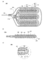
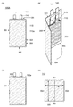
二次電池100の斜視図を図1(A)に示す。二次電池100は、可撓性を有する外装体110、正極リード141、負極リード145及び封止層140を有する。また、二次電池100は、図1(B)に示すように湾曲することができる。
[1. Basic configuration]
A perspective view of the
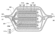
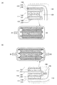
二次電池100のX1−X2線における断面図を図2(A)に、X3−X4線における断面図を図3(A)に、Y1−Y2線における断面図を図4に示す。また、図1(B)に示した湾曲した二次電池100のX5−X6線における断面図を図5に示す。
The cross-sectional view of the
二次電池100は、外装体110に囲まれる位置に、正極111、負極115、セパレータ108及び電解液109を有する。また、正極111は、正極集電体101及び正極活物質層102を有する。また、負極115は、負極集電体105及び負極活物質層106を有する。また、正極集電体101、負極集電体105及びセパレータ108は、重ねられ、つづら折りに折り曲げられている。また、正極活物質層102及び負極活物質層106は、セパレータ108を介して向かい合っている。
The
二次電池100において、正極集電体101及び負極集電体105をつづら折りに折り曲げることによって、正極111及び負極115の面積がそれぞれ大きくても、小さく折り畳むことができる。これによって、大容量の二次電池100を小型化することができる。
In the
なお、本明細書等において、つづら折りとは、板状の部材で作られる山折りと谷折りの繰り返し構造を示す。 In the present specification and the like, the zigzag fold means a repeated structure of mountain fold and valley fold made of a plate-shaped member.
なお、本明細書等において、折り曲げ部とは、板状の部材を折り曲げることにより形成される局所的に屈曲した部分、または、板状の部材を折り曲げることにより分けられる一方の平板状の部分と、他方の平板状の部分との境に位置する部分を示す。 In the present specification and the like, the bent portion is a locally bent portion formed by bending a plate-shaped member or a flat plate-shaped portion separated by bending a plate-shaped member. , The part located at the boundary with the other flat plate-shaped part is shown.
なお、本明細書等において、平板状とは、板状の部材が折り曲げ部を有していない状態を示す。また、本明細書等において、平板状の部分は、湾曲していてもよい。 In the present specification and the like, the flat plate shape means a state in which the plate-shaped member does not have a bent portion. Further, in the present specification and the like, the flat plate-shaped portion may be curved.
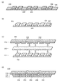
次に、図2(A)乃至(E)、及び図3(D)を用いて、負極115の構造について説明する。
Next, the structure of the
図2(A)に示した二次電池100が有する負極115において、点線で囲まれる部分115aの拡大図を図2(B)に、部分115aが湾曲する様子を図2(C)に示す。また、図2(B)に示した部分115aにおいて、点線で囲まれる部分202の拡大図を図2(E)に示す。図2(B)および図2(E)に示すように、負極集電体105は、第1の面221と第2の面222を有し、第2の面222を内側とする折り曲げ部211を有する。負極活物質層106は、第1の面221に設けられ、第2の面222には設けられない。また、第2の面222は、折り曲げ部211を境として互いに向かい合う第1の領域231と、第2の領域232に分かれる。
In the
図2(B)では、簡略化のため図示しないが、本構成とすることにより、第1の領域231と、第2の領域232とは、接触する。第1の領域231及び第2の領域232は、いずれも負極集電体105を構成する金属の表面であることから、第1の領域と、第2の領域との接触面に働く摩擦力は小さい。例えば、より具体的には、第1の領域231と、第2の領域232と間の静摩擦係数は、負極活物質層106と、セパレータ108との間の静摩擦係数よりも小さい。従って、第1の領域231と、第2の領域232が、互いにずれることによって、図2(C)に示すように、負極集電体105は変形することができる。
Although not shown in FIG. 2B for simplification, the
また、図2(B)、(C)で示すように、第1の領域231の端部と、第2の領域232の端部とは、折り曲げ部211とは異なる箇所である、溶接部201aで接続されている。これによって、負極集電体105、さらには負極115が、過剰に変形し、正極活物質層102と負極活物質層106との距離が変化すること、又は負極115と正極111が接触して短絡が発生すること等を防ぐことができる。
Further, as shown in FIGS. 2B and 2C, the end portion of the
また、負極115は、折り曲げ部211の付近に負極活物質層106を有しないと好ましい。これによって、折り曲げ部211付近における負極集電体105の変形を、負極活物質層106が妨げることを防ぐことができる。また、二次電池100の製造工程において、負極集電体105を折り曲げ、折り曲げ部211を形成する際に、負極活物質層106が、負極集電体105から剥離することを防ぐことができる。
Further, it is preferable that the
上記の構成によって、二次電池100が湾曲する際に、負極115は、二次電池100全体の変形に追随して、変形することができる。従って、二次電池100を、可撓性を有する二次電池とすることができる。また、以上に記した構成によって、第1の領域231と、第2の領域232とは、互いにずれやすく、負極集電体105が変形しやすくすることができる。そのため、負極115に皺が生じること、又は負極115が局所的に強く湾曲すること等を抑制することができる。よって、負極115において、負極活物質層106が損傷すること、又は負極集電体105が破れること等を防ぐことができる。従って、湾曲することにより、二次電池100の容量及びサイクル特性が悪化するのを抑制することができる。
With the above configuration, when the
図2(D)には、図2(A)で示す溶接部201の拡大図を示す。負極集電体105は、第1の面221を内側とする折り曲げ部212を有する。
FIG. 2D shows an enlarged view of the welded
図2(D)に示すように、負極活物質層106を、第1の面221を内側とする折り曲げ部212に設けないことによって、負極集電体105の折り曲げ部212付近と、負極集電体105のふち213とを重ねて溶接し、溶接部201を形成することができる。また、溶接部201を形成することによって、負極集電体105のつづら折りの構造が崩れることを抑制することができる。また、溶接部201に、負極リード145を接続することで、負極115の内部抵抗を小さくすることができる。従って、二次電池100のサイクル特性を改善し、また、充放電容量を増加させることができる。
As shown in FIG. 2D, by not providing the negative electrode
また、負極115が有する負極集電体105において、折り曲げ部212と、折り曲げ部211とが、平行又は略平行であると好ましい。折り曲げ部212と、折り曲げ部211とが、互いに平行又は略平行であることにより、二次電池100は、少なくとも、折り曲げ部212または折り曲げ部211に対して垂直な軸方向に折り曲げやすくなる。
Further, in the negative electrode
なお、例えば、板状の部材Aが有する折り曲げ部(以下折り曲げ部Aと呼ぶ)に隣接する平板状の部分(以下、平板状の部分Aと呼ぶ)に垂直な向きから板状の部材Aを観察するとき、折り曲げ部Aの一部を、板状の部材Aの有する一つの辺(以下辺Aと呼ぶ)として認識することができる。また、例えば、板状の部材Bが有する折り曲げ部(以下折り曲げ部Bと呼ぶ)に隣接する平板状の部分(以下、平板状の部分Bと呼ぶ)に垂直な向きから板状の部材Bを観察するとき、折り曲げ部Bの一部を、板状の部材Bの有する一つの辺(以下辺Bと呼ぶ)として認識することができる。本明細書において、折り曲げ部Aと、折り曲げ部Bとが、平行であるとは、辺Aと、辺Bとが、平行であることを示す。なお、上記した板状の部材Bは、板状の部材Aと同一であってもよく、別の板状の部材であってもよい。 In addition, for example, the plate-shaped member A is arranged from the direction perpendicular to the flat plate-shaped portion (hereinafter referred to as the flat plate-shaped portion A) adjacent to the bent portion (hereinafter referred to as the bent portion A) of the plate-shaped member A. When observing, a part of the bent portion A can be recognized as one side (hereinafter referred to as side A) of the plate-shaped member A. Further, for example, the plate-shaped member B is provided from a direction perpendicular to the flat plate-shaped portion (hereinafter referred to as the flat plate-shaped portion B) adjacent to the bent portion (hereinafter referred to as the bent portion B) of the plate-shaped member B. When observing, a part of the bent portion B can be recognized as one side (hereinafter referred to as side B) of the plate-shaped member B. In the present specification, the fact that the bent portion A and the bent portion B are parallel means that the side A and the side B are parallel. The plate-shaped member B described above may be the same as the plate-shaped member A, or may be another plate-shaped member.
また、上記したように、本明細書において「平行」とは、二つの直線が−10°以上10°以下の角度で配置されている状態をいう。そのため、折り曲げ部Aと折り曲げ部Bとが、平行であるとは、辺Aと、辺Bとが、−10°以上10°以下の角度で配置されている状態をいう。 Further, as described above, "parallel" in the present specification means a state in which two straight lines are arranged at an angle of −10 ° or more and 10 ° or less. Therefore, the fact that the bent portion A and the bent portion B are parallel means that the side A and the side B are arranged at an angle of −10 ° or more and 10 ° or less.
また、上記したように、本明細書において「略平行」とは、二つの直線が−30°以上30°以下の角度で配置されている状態をいう。そのため、折り曲げ部Aと折り曲げ部Bとが、略平行であるとは、辺Aと、辺Bとが、−30°以上30℃以下の角度で配置されている状態をいう。 Further, as described above, "substantially parallel" in the present specification means a state in which two straight lines are arranged at an angle of −30 ° or more and 30 ° or less. Therefore, the fact that the bent portion A and the bent portion B are substantially parallel means that the side A and the side B are arranged at an angle of −30 ° or more and 30 ° or less.
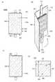
図3(D)に、つづら折りの負極集電体105における平板状の部分に垂直な向きから負極115を観察する様子を示す。図3(D)において、折り曲げ部211の一部を、負極集電体105の有する一つの辺281として認識することができる。また、図3(D)において、折り曲げ部212の一部を、負極集電体105の有する一つの辺282として認識することができる。
FIG. 3D shows a state in which the
次に、図3(A)、(B)を用いて、正極111について説明する。
Next, the
正極111において、正極活物質層102は、正極集電体101の一方の面にのみ設けられる。正極集電体101は、負極集電体105及びセパレータ108と同様につづら折りに折り曲げられ、複数の折り曲げ部を形成している。
In the
図3(A)で示すように、正極集電体101は、第4の面224を内側とする折り曲げ部252を有している。正極集電体101が、折り曲げ部252を有する場合、折り曲げ部252は、負極集電体105が有する折り曲げ部211と平行又は略平行であることが好ましい。また、折り曲げ部252と、折り曲げ部251とが、平行であれば、より好ましい。上記の構成とすることによって、二次電池100を湾曲しやすくすることができる。
As shown in FIG. 3A, the positive electrode
また、正極111が有する正極集電体101において、折り曲げ部252と、折り曲げ部251とが、互いに平行又は略平行であることにより、二次電池100は、折り曲げ部251または折り曲げ部252に垂直な軸方向に折り曲げやすくなり、好ましい。
Further, in the positive electrode
図3(C)に、つづら折りの正極集電体101における平板状の部分に垂直な向きから正極111を観察する様子を示す。図3(C)において、折り曲げ部251の一部を、正極集電体101の有する一つの辺283として認識することができる。また、図3(C)において、折り曲げ部252の一部を、正極集電体101の有する一つの辺284として認識することができる。
FIG. 3C shows a state in which the
また、図3(A)で、点線250で囲んだ部分の断面斜視図を、図3(B)に示す。正極集電体101は、正極活物質層102が設けられる第3の面223および正極活物質層102が設けられない第4の面224並びに第3の面223を内側とする折り曲げ部251を有している。また、図3(B)には、図3(D)を用いて説明した辺281を両矢印291で示し、図3(C)を用いて説明した辺283を両矢印293で示す。
Further, in FIG. 3A, a cross-sectional perspective view of the portion surrounded by the dotted
図3(B)に示すように、両矢印291と、両矢印293とが平行又は略平行である、すなわち、正極集電体101の折り曲げ部251が、負極集電体105の折り曲げ部211と平行又は略平行であることによって、二次電池100は、少なくとも正極集電体101の折り曲げ部251に垂直な軸方向、または負極集電体105の折り曲げ部211に垂直な軸方向に、図5のように折り曲げることができる。
As shown in FIG. 3B, the
正極集電体101は、端部において、正極リード141と接続されている。
The positive electrode
なお、図2および図3に示すように、負極115において、一の負極集電体105の一方の面に、負極活物質層106を複数有し、複数の負極活物質層106の間に折り曲げ部を設けると好ましい。また、正極111において、一の正極集電体101の一方の面に、正極活物質層102を複数有し、複数の正極活物質層102の間に折り曲げ部を設けると好ましい。
As shown in FIGS. 2 and 3, in the
また、本実施の形態では、正極集電体101、負極集電体105、及びセパレータ108それぞれが有する折り曲げ部の数が5である例を示したが、本実施の形態にはこれに限られない。正極集電体101、負極集電体105、及びセパレータ108の有する折り曲げ部の数は、それぞれ、1以上4以下でもよく、6以上であってもよい。
Further, in the present embodiment, an example is shown in which the number of bent portions of each of the positive electrode
正極111における正極活物質層102の面積、及び負極115における負極活物質層106の面積が大きいほど、二次電池100の容量を増加させることができ、好ましい。また、正極集電体101又は負極集電体105が有する折り曲げ部の数が多いほど、二次電池100を小型化することができ、好ましい。
The larger the area of the positive electrode
また、以上に示した構成とすると、一の集電体に一の活物質層が設けられる電極を複数重ねる構成の二次電池と比較して、部品数を減らすことができ、製造を容易にすることができる。また、製造時に正極と負極の位置を合わせやすくすることができる。したがって、二次電池の小型化が要求されるとき、例えば、人間の手では製造が難しくなる大きさの二次電池を製造する場合にも、二次電池100は、製造が容易である。したがって、二次電池100は、大量生産することが容易な二次電池であるということもできる。
Further, with the configuration shown above, the number of parts can be reduced and manufacturing can be facilitated as compared with a secondary battery having a configuration in which a plurality of electrodes having one active material layer provided in one current collector are stacked. can do. In addition, it is possible to easily align the positions of the positive electrode and the negative electrode during manufacturing. Therefore, when miniaturization of the secondary battery is required, for example, even when manufacturing a secondary battery having a size that is difficult to manufacture by human hands, the
なお、図2乃至図5では、負極115の有する負極集電体105について、第2の面222を内側とする折り曲げ部211により分けられる第1の領域231と、第2の領域232を接続する例を示したが、本実施の形態は、これに限られない。第1の面221を内側とする折り曲げ部212により分けられる2つの領域同士を接続してもよい。また、正極111の有する正極集電体101について、第3の面223を内側とする折り曲げ部251により分けられる2つの領域同士を接続する構成としてもよい。また、正極集電体101について、第4の面224を内側とする折り曲げ部252により分けられる2つの領域同士を接続する構成としてもよい。
In FIGS. 2 to 5, regarding the negative electrode
また、本明細書において、正極と負極は、必要に応じて適宜入れ替えて使用してもよい。 Further, in the present specification, the positive electrode and the negative electrode may be appropriately interchanged and used as needed.
[2.変形例1]
次に、図6(A)、(B)を用い正極111の別の構成について説明する。負極115、セパレータ108、外装体110及び電解液109については、上述した基本的な構成の二次電池100に関する説明を参照することができる。
[2. Modification 1]
Next, another configuration of the
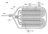
図6(A)に、二次電池100の斜視図を示し、図6(B)に、二次電池100のX7−X8線における断面図を示す。
6 (A) shows a perspective view of the
図6(A)に示す二次電池100のように、正極リード141と、負極リード145を、外装体110に対してそれぞれ逆向きにとりつける場合、正極リード141と正極111との接続は、負極リード145の負極115との接続と同様にすればよい。すなわち、図6(B)に示すように、正極集電体101の折り曲げ部は、溶接部261で接続されてもよい。これによって、正極集電体101のつづら折りの構造が崩れることを抑制することができる。
When the
また、溶接部261には、正極リード141を接続すればよい。これによって、正極111の内部抵抗を減少させることができる。従って、二次電池100のサイクル特性を改善し、また、充放電容量を増加させることができる。
Further, the
このように、本発明の一態様の二次電池100は、リード電極を自由に配置することができるため、設計自由度が高い。よって、本発明の一態様の二次電池を用いた製品の設計自由度を高めることができる。また、本発明の一態様の二次電池を用いた製品の生産性を高めることができる。
As described above, the
また、正極111及び負極115のいずれか一方は、図2乃至図6に示すようなつづら折りに折り曲げずともよい。例えば、図7に示す二次電池100の有する正極111a及び正極111bのように平板状であってもよい。正極111aは、正極集電体101の片方の面に設けられる正極活物質層102を有し、正極活物質層102は、負極活物質層106と、セパレータ108aを介して向かい合う。また、正極111bは、正極集電体101の両方の面に設けられる正極活物質層102を有し、正極活物質層102は、負極活物質層106と、セパレータ108bを介して向かい合う。
Further, either one of the
また、セパレータ108もつづら折りに折り曲げずともよい。例えば、図7に示す二次電池100の有するセパレータ108a及びセパレータ108bのように、正極を挟み込む形状であってもよい。セパレータ108aは、正極111aを挟み込み、また、セパレータ108bは、正極111bを挟み込む。セパレータ108が、111aを挟み込むことにより、二次電池100において内部短絡が発生することをより確実に防止することができる。
Further, the
[3.変形例2]
次に、図8および図9を用いて負極115の別の構成について説明する。正極111、セパレータ108、外装体110、及び電解液109については、上述の説明を参照することができる。
[3. Modification 2]
Next, another configuration of the
図8(A)に、二次電池100の断面図を示す。二次電池100において、負極115は、負極集電体105、負極活物質層106、及び摩擦層107を有する。また、負極集電体105は、つづら折りに折り曲げられ、複数の折り曲げ部を有している。
FIG. 8A shows a cross-sectional view of the
図8(A)に示した負極115において、点線で囲まれる部分115bの拡大図を図8(B)に示す。負極集電体105は、第1の面221と第2の面222を有し、第2の面222を内側として折り曲げられ、折り曲げ部211を形成している。負極活物質層106は、第1の面221に設けられ、摩擦層107は、第2の面222に設けられる。
In the
図8(B)に示した部分115bの点線で囲まれる部分202の拡大図を図8(C)に示す。負極集電体105の第2の面222は、折り曲げ部211を境として分けられる第1の領域231と、第2の領域232とを有する。また、第1の領域231と、第2の領域232は、向かい合う。摩擦層107は、第1の領域231にのみ設けられ、第2の領域232には設けない。
An enlarged view of the
この構成とすることにより、第1の領域231に設けられる摩擦層107は、第2の領域232と接触する。後述するが、摩擦層107には、他の物質との接触面に働く摩擦力が小さい材料を用いるため、摩擦層107と、第2の領域232とが接触する本構成とすることにより、負極集電体105をより変形しやすくすることができる。
With this configuration, the
摩擦層107と、第2の領域232との間の静摩擦係数が、第1の領域231と、第2の領域232との間の静摩擦係数よりも小さい場合に、本構成とすることにより、負極集電体105を、より変形しやすくすることができ、好ましい。
When the coefficient of static friction between the
なお、本明細書等における静摩擦係数は、傾斜法による測定や、直線摺動式試験機を用いた測定により、求めることができる。 The coefficient of static friction in the present specification and the like can be obtained by measurement by an inclination method or measurement using a linear sliding tester.
また、本明細書等における静摩擦係数は、以下のように求めることができる。まず表面が平らで、水平になるように置かれたガラス板の上に、試料Aと、試料Bをのせる。その上に平らな板と重りをのせる。試料Aを固定し、試料Bに荷重試験機をつけて、荷重試験機を例えば約1mm/秒で水平に引っ張る。試料Bが1cm動くまでの間の荷重の最大値を測定し、この測定値を最大摩擦力とする。最大摩擦力をFとし、平らな板、重り、及び試料Bの荷重による試料Aに対する垂直抗力をNとするとき、試料Aと試料Bとの間の静摩擦係数μは、μ=N/Fで求めることができる。 In addition, the coefficient of static friction in the present specification and the like can be obtained as follows. First, sample A and sample B are placed on a glass plate placed so that the surface is flat and horizontal. Place a flat plate and weight on it. The sample A is fixed, a load tester is attached to the sample B, and the load tester is pulled horizontally at, for example, about 1 mm / sec. The maximum value of the load until the sample B moves by 1 cm is measured, and this measured value is taken as the maximum frictional force. When the maximum frictional force is F and the normal force against the sample A due to the load of the flat plate, the weight, and the sample B is N, the coefficient of static friction μ between the sample A and the sample B is μ = N / F. You can ask.
なお、本明細書等における静摩擦係数は、平らで水平なガラス板の上に、測定する電極をのせ、試料Bの上下を試料Aにはさまれている状態としても、測定することができる。 The coefficient of static friction in the present specification and the like can be measured even when the electrode to be measured is placed on a flat and horizontal glass plate and the upper and lower parts of the sample B are sandwiched between the sample A.
なお、試料Aと、試料Bとの間に液が存在すると、静摩擦係数は小さくなることがある。二次電池として使用する際に、電解液が存在する可能性がある摩擦面について静摩擦係数の測定をする場合には、試料Aと、試料Bとの間に電解液を供給してから、測定を行うと、より好ましい。また、二次電池において、例えばゲル状の電解液を用いる場合等には、摩擦面に電解液が供給されにくいことがある。このような二次電池に用いる電極について、静摩擦係数の測定を行う場合には、試料Aと試料Bとの間に電解液を供給しなくてもよい。 If a liquid is present between the sample A and the sample B, the coefficient of static friction may become small. When measuring the coefficient of static friction on the friction surface where the electrolytic solution may exist when using it as a secondary battery, measure after supplying the electrolytic solution between the sample A and the sample B. Is more preferable. Further, in a secondary battery, for example, when a gel-like electrolytic solution is used, it may be difficult to supply the electrolytic solution to the friction surface. When measuring the coefficient of static friction of the electrodes used in such a secondary battery, it is not necessary to supply the electrolytic solution between the sample A and the sample B.
なお、図8(A)、(B)、(C)では、負極115が摩擦層107を有する例を示したが、本発明の一態様はこれに限られず、正極111が摩擦層107を有していてもよい。
8 (A), (B), and (C) show an example in which the
また、図8(A)、(B)、(C)では、負極集電体105の第2の面222の一部である第1の領域231にのみ、摩擦層107を設ける例を示したが、本発明の一態様はこれに限られず、例えば、負極集電体105の第2の面222の全体、また、正極集電体101の正極活物質層102を有しない第4の面224の全体に、摩擦層107を設けてもよい。
Further, FIGS. 8A, 8B, and 8C show an example in which the
例えば、図9(A)に示す二次電池100の断面図において、正極111と、負極115は、いずれも摩擦層107を有する。本構成により、正極集電体101及び負極集電体105の両方を、より変形しやすくすることができる。従って、二次電池100が湾曲する際に、正極111及び負極115の両方を、二次電池100全体の変形に追随して、変形しやすくすることができる。
For example, in the cross-sectional view of the
図9(A)に示した負極115において、点線で囲まれる部分115cの拡大図を図9(B)に示す。負極集電体105は、第1の面221と第2の面222を有し、第2の面222を内側として折り曲げられ、折り曲げ部211を形成している。負極活物質層106は、第1の面221に設けられ、摩擦層107は、第2の面222に設けられている。
In the
図9(B)に示した部分115cの点線で囲まれる部分の拡大図を図9(D)に示す。負極集電体105の第2の面222は、折り曲げ部211を境として第1の領域231と、第2の領域232と分けられ、第1の領域231と、第2の領域232は、向かい合う。摩擦層107は、第1の領域231と、第2の領域232の両方に設けられる。
An enlarged view of the portion surrounded by the dotted line of the
摩擦層107と、摩擦層107との間の静摩擦係数が、摩擦層107と、第1の領域231又は第2の領域232との間の静摩擦係数よりも小さい場合に、本構成とすることにより、負極集電体105を、より変形しやすくすることができ、好ましい。
This configuration is used when the coefficient of static friction between the
なお、摩擦層107が、導電性を有しない材料からなる場合に、負極集電体105において、折り曲げ部212及び溶接部201の付近に摩擦層107を有すると、負極集電体105の第1の領域231と、第2の領域232を接続することが困難になる。従って、図8(A)、(B)及び図9(A)、(B)に示すように、負極集電体105において、折り曲げ部212及び溶接部201の付近には、摩擦層107を有しない方が好ましい。
When the
一方、摩擦層107が導電性を有する材料からなる場合には、負極集電体105において、折り曲げ部212及び溶接部201の付近に摩擦層107を有していても、負極集電体105の第1の領域231と、第2の領域232を接続することができる。従って、図9(C)の溶接部201の拡大図に示すように、摩擦層107が、折り曲げ部212及び溶接部201の付近に設けられていてもよい。
On the other hand, when the
[4.変形例3]
次に、図10を用いて二次電池100の別の構成について説明する。
[4. Modification 3]
Next, another configuration of the
図10に示す二次電池100は、正極111、負極115、セパレータ108及びゲル電解液109aを有する。また、正極111は、正極集電体101及び正極活物質層102を有する。また、負極115は、負極集電体105及び負極活物質層106を有する。正極集電体101、負極集電体105及びセパレータ108は、つづら折りに折り曲げられ、それぞれ複数の折り曲げ部を有する。また、正極活物質層102及び負極活物質層106は、セパレータ108及びゲル電解液109aを介して向かい合っている。また正極集電体101は、正極リード141と接続している。また、負極集電体105は、負極リード145と接続している。
The
正極111と、負極115との間にゲル電解液109aを設けると、正極活物質層102と、負極活物質層106との間の距離を一定に保ちやすくすることができる。そのため、正極111と、負極115との間の電池反応の速度を一定に保ちやすくすることができる。従って、本構成とすると、二次電池100が湾曲した際に、正極活物質層102と、負極活物質層106との間の距離を一定に保つことで、正極111と負極115との間の電池反応の速度がばらつくことを防ぎ、二次電池100の容量及びサイクル特性の悪化を抑制することができる。
When the gel
[5.変形例4]
図11乃至図23を用いて、二次電池100のさらなる変形例を示す。なお、図11乃至図23に示す正極111、負極115、セパレータ108、外装体110及び電解液109等について、特に説明しない場合は、変形例1乃至3の説明を参酌することができる。
[5. Modification 4]
11 to 23 are used to show further modifications of the
図11(A)に、図1で示した二次電池100のX1−X2線における断面図の変形例を、図11(B)に、二次電池100のX3−X4線における断面図の変形例を示す。
11 (A) shows an example of deformation of the cross-sectional view of the
図11(A)、(B)に示すように、場合によっては、負極115において、負極集電体105の第1の面と、第2の面とが、溶接により接続されていなくてもよい。負極集電体105は、溶接部201を有しない場合であっても、負極タブにおいて、負極リード145と接続することができる。
As shown in FIGS. 11A and 11B, in some cases, in the
なお、負極タブとは、負極のうち、負極リードと電気的に接続するための、活物質が形成されていない領域を有する部分をいう。同様に、正極タブとは、正極のうち、正極リードと電気的に接続するための、活物質が形成されていない領域を有する部分をいう。 The negative electrode tab refers to a portion of the negative electrode having a region in which an active material is not formed for electrically connecting to the negative electrode lead. Similarly, the positive electrode tab refers to a portion of the positive electrode having a region in which an active material is not formed for electrically connecting to the positive electrode lead.
図12(A)に、図1で示した二次電池100のX1−X2線における断面図の別の変形例を、図12(B)に、二次電池100のX3−X4線における断面図の別の変形例を示す。
12 (A) shows another modified example of the cross-sectional view of the
図12(A)、(B)に示すように、場合によっては、負極115において、負極集電体105は、図2(D)で示した折り曲げ部212に相当する折り曲げ部を有していなくてもよい。複数の2つ折りの負極集電体105を溶接部201で接続する構成であれば、溶接部201で負極リード145と接続することができる。
As shown in FIGS. 12A and 12B, in some cases, in the
図13(A)に、図1で示した二次電池100のX1−X2線における断面図の別の変形例を、図14に、X3−X4線における断面図の別の変形例を示す。また、図13(B)に、図13(A)において点線部で囲った部分115aの拡大図を示す。
13 (A) shows another modified example of the cross-sectional view of the
図13(A)、(B)及び図14に示すように、場合によっては、負極115において、負極集電体105は、図2(E)で示した折り曲げ部211に相当する折り曲げ部を有していなくてもよい。2つの負極集電体105の、負極活物質層106を有しない面(第1の領域231を含む第2の面222と、第2の領域232を含む第2の面222)同士を、溶接部211aで接続する構成であってもよい。
As shown in FIGS. 13 (A), 13 (B) and 14, in some cases, in the
図15(A)に、図1で示した二次電池100のX1−X2線における断面図の別の変形例を、図15(B)に、二次電池100のX3−X4線における断面図の別の変形例を示す。
15 (A) shows another modified example of the cross-sectional view of the
図15(A)、(B)に示すように、場合によっては、正極111において、正極集電体101は、図3 で示した折り曲げ部252に相当する折り曲げ部を有していなくてもよい。2つの正極集電体101の、正極活物質層102を有しない面同士を、溶接部252aで接続する構成であってもよい。
As shown in FIGS. 15A and 15B, in some cases, in the
図16(A)に、図1 で示した二次電池100のX1−X2線における断面図の別の変形例を、図16(B)に、二次電池100のX3−X4線における断面図の別の変形例を示す。
16 (A) shows another modified example of the cross-sectional view of the
図16(A)、(B)に示すように、正極111において、正極集電体101は、図3(B)で説明した折り曲げ部251に相当する折り曲げ部を有していなくてもよい。2つの正極集電体101の、正極活物質層102を有しない面同士を、溶接部251aで接続する構成であってもよい。
As shown in FIGS. 16A and 16B, in the
図17に、図6(A)で示す二次電池100のX7−X8線における断面図の変形例を示す。
FIG. 17 shows a modified example of the cross-sectional view of the
図17に示すように、正極111aおよび正極111bが平板状の場合に、負極115において、負極集電体105の第1の面と、第2の面が接続されていなくてもよい。負極集電体105は、溶接部を有しない場合であっても、端部に有する負極タブにおいて、負極リード145と接続することができる。
As shown in FIG. 17, when the
図18に、図6(A)で示す二次電池100のX7−X8線における断面図の別の変形例を示す。
FIG. 18 shows another modification of the cross-sectional view taken along the line X7-X8 of the
図18に示すように、正極111aおよび正極111bが平板状の場合に、負極115において、負極集電体105が、図2 で示した折り曲げ部212に相当する折り曲げ部を有していなくてもよい。複数の2つ折りの負極集電体105を溶接部201で接続する構成であれば、溶接部201で負極リード145と接続することができる。
As shown in FIG. 18, when the
図19に、図6(A)で示す二次電池100のX7−X8線における断面図の別の変形例を示す。
FIG. 19 shows another modification of the cross-sectional view taken along the line X7-X8 of the
図19に示すように、正極111aおよび正極111bが平板状の場合であっても、負極115において、負極集電体105は、図2 で示した折り曲げ部211を有していなくてもよい。2つの負極集電体105の、負極活物質層106を有しない面同士を、溶接部211aで接続する構成であってもよい。
As shown in FIG. 19, even when the
図20に、図6(A)で示す二次電池100のX7−X8線における断面図の別の変形例を示す。
FIG. 20 shows another modification of the cross-sectional view of the
正極111は、つづら折りでも平板状でもない形状であってもよい。図20に示す正極111は、正極集電体101の一部においては両面に正極活物質層102が設けられ、正極集電体101の他の一部においては一方の面にのみ正極活物質層102が設けられる。このような正極111を溶接部261で接続する構成であってもよい。
The
図21乃至図23に、摩擦層107を有する二次電池100の別の変形例を示す。
21 to 23 show another modification of the
図21に示すように、正極111のみが摩擦層107を有していてもよい。
As shown in FIG. 21, only the
また、図22に示すように、正極111及び負極115の両方が摩擦層107を有する場合であって、摩擦層107は、正極集電体101及び負極集電体105それぞれの一部のみに設けられる構成であってもよい。
Further, as shown in FIG. 22, both the
また、図23に示すように、二次電池100は、摩擦層107を有する負極115、及びつづら折りの正極111a、並びに平板状の正極111bを有する構成であってもよい。
Further, as shown in FIG. 23, the
[6.材料]
次に、二次電池100を構成する材料について説明する。
[6. material]
Next, the materials constituting the
正極集電体101及び負極集電体105には、ステンレス、金、白金、鉄、銅、アルミニウムまたはチタン等の金属、及びこれらの金属の合金など、導電性が高く、リチウム等のキャリアイオンと合金化しない材料を用いることができる。また、シリコン、チタン、ネオジム、スカンジウム、モリブデンなどの耐熱性を向上させる元素が添加されたアルミニウム合金を用いることができる。また、シリコンと反応してシリサイドを形成する金属元素で形成してもよい。シリコンと反応してシリサイドを形成する金属元素としては、ジルコニウム、チタン、ハフニウム、バナジウム、ニオブ、タンタル、クロム、モリブデン、タングステン、コバルト、ニッケル等がある。集電体は、箔状、板状(シート状)、網状、パンチングメタル状、エキスパンドメタル状等の形状を適宜用いることができる。集電体は、厚みが5μm以上30μm以下のものを用いるとよい。また、集電体の表面に、グラファイトなどを用いてアンダーコート層を設けてもよい。
The positive electrode
摩擦層としては、導電性を有する膜でも、絶縁性を有する膜でもよく、有機膜、無機膜、金属膜等を用いることができる。 The friction layer may be a conductive film or an insulating film, and an organic film, an inorganic film, a metal film, or the like can be used.
有機膜の例として、樹脂膜、または、低分子化合物により形成される膜が挙げられる。 Examples of the organic film include a resin film or a film formed of a low molecular weight compound.
樹脂膜は、エポキシ樹脂、アクリル樹脂、シリコーン樹脂、フェノール樹脂、ポリエステル樹脂等の熱硬化性樹脂から選ばれる一種若しくは複数種の樹脂材料、またはポリプロピレン、ポリエチレン、ポリカーボネート、ポリスチレン、ポリアミド、ポリエーテルケトン、フッ素樹脂、ポリエチレンナフタレート等の熱可塑性樹脂から選ばれる一種若しくは複数種の樹脂材料を用いて形成することができる。また、ポリオキシメチレンを用いてもよい。特に、フッ素樹脂は、同材料同士の静摩擦係数が約0.04であるポリテトラフルオロエチレンに代表されるように、摺動性が高く、摩擦層の摺動性を向上させることができ、好ましい。また、電池反応の電位において、摩擦層の分解が生じないことが好ましい。例えば、負極の電池反応の電位が低い場合、フッ素樹脂は還元分解してしまうことがある。そのため、フッ素樹脂は、正極の摩擦層として用いることが好適である。また、ポリエーテルエーテルケトン(PEEK)に代表されるポリエーテルケトンは、摺動性、耐熱性、耐疲労性、耐薬品性に優れるため、摩擦層の摺動性を向上させることができ、好ましい。また、ポリパラキシリレン樹脂を、化学蒸着法(CVD)で形成してもよい。ポリパラキシリレン樹脂は、摺動性、耐熱性、耐薬品性に優れるため、摩擦層の摺動性を向上させることができ、好ましい。 The resin film is one or more resin materials selected from thermosetting resins such as epoxy resin, acrylic resin, silicone resin, phenol resin, polyester resin, or polypropylene, polyethylene, polycarbonate, polystyrene, polyamide, polyether ketone, It can be formed by using one or more kinds of resin materials selected from thermoplastic resins such as fluororesins and polyethylene naphthalates. Further, polyoxymethylene may be used. In particular, fluororesin is preferable because it has high slidability and can improve the slidability of the friction layer, as represented by polytetrafluoroethylene having a coefficient of static friction between the same materials of about 0.04. .. Further, it is preferable that the friction layer does not decompose at the potential of the battery reaction. For example, when the potential of the battery reaction of the negative electrode is low, the fluororesin may be reduced and decomposed. Therefore, it is preferable to use the fluororesin as the friction layer of the positive electrode. Further, the polyetherketone typified by polyetheretherketone (PEEK) is excellent in slidability, heat resistance, fatigue resistance, and chemical resistance, so that the slidability of the friction layer can be improved, which is preferable. .. Further, the polyparaxylylene resin may be formed by a chemical vapor deposition method (CVD). Since the polyparaxylylene resin is excellent in slidability, heat resistance, and chemical resistance, the slidability of the friction layer can be improved, which is preferable.
低分子化合物により形成される膜として、自己組織化単分子膜(SAM:Self−Assembled Monolayer)を用いてもよい。集電体の表面にSAMを形成することにより、集電体表面の潤滑性を向上させ、また、電極の摺動性を向上させることができ、好ましい。また、撥液性SAMを用いてもよい。撥液性SAMとして、例えば、フルオロアルキル基を有するシランカップリング剤(フルオロアルキルシラン。以下、FASという。)を用いればよい。加熱した集電体とFASを封じ込め、気相反応によって集電体表面にFAS自己組織化単分子膜を形成することができる。また、メラミンシアヌレート(MCA)等の固体潤滑剤を、蒸着することによって集電体上に摩擦層を形成してもよい。 As a film formed of a low molecular weight compound, a self-assembled monolayer (SAM: Self-Assembled Monolayer) may be used. By forming the SAM on the surface of the current collector, the lubricity of the surface of the current collector can be improved and the slidability of the electrodes can be improved, which is preferable. Further, a liquid-repellent SAM may be used. As the liquid-repellent SAM, for example, a silane coupling agent having a fluoroalkyl group (fluoroalkylsilane, hereinafter referred to as FAS) may be used. The heated current collector and FAS can be contained, and a FAS self-assembled monolayer can be formed on the surface of the current collector by a gas phase reaction. Further, a friction layer may be formed on the current collector by depositing a solid lubricant such as melamine cyanurate (MCA) on the current collector.
無機膜及び金属膜として、集電体に付着することができる材料を用いることができる。また、リチウムイオンの挿入及び脱離を起こさず、また、リチウムと合金化・脱合金化反応を起こさない材料を用いると、特に好ましい。例えば無機膜として、固体潤滑剤として代表的な二硫化モリブデン(MoS2)、又は二硫化タングステン(WS2)等の金属硫化物、窒化ホウ素(BN)等を用いると電極の摺動性を向上させることができる。また、無機膜は絶縁性を有していてもよく、酸化シリコン、酸化窒化シリコン、酸化ガリウム、酸化窒化ガリウム、酸化イットリウム、酸化窒化イットリウム、酸化ハフニウム、酸化窒化ハフニウム等の酸化物絶縁膜、窒化シリコン、窒化アルミニウム等の窒化物絶縁膜を用いることができる。 As the inorganic film and the metal film, a material that can adhere to the current collector can be used. Further, it is particularly preferable to use a material that does not cause insertion and desorption of lithium ions and does not cause an alloying / dealloying reaction with lithium. For example, when a typical solid lubricant such as molybdenum disulfide (MoS 2 ), metal sulfide such as tungsten disulfide (WS 2 ), or boron nitride (BN) is used as the inorganic film, the slidability of the electrode is improved. Can be made to. Further, the inorganic film may have an insulating property, and is an oxide insulating film such as silicon oxide, silicon nitride, gallium oxide, gallium oxide, yttrium oxide, yttrium oxide, hafnium oxide, or hafnium oxide. A nitride insulating film such as silicon or aluminum nitride can be used.
金属膜として、例えば、アルミニウム、金、白金、銀、ニッケル、タングステン、クロム、モリブデン、鉄、コバルト、銅、もしくはパラジウム等の金属材料、又はこれら金属材料を含む合金を用いることができる。また、上記金属材料や合金に、ランタン、ネオジム、又はゲルマニウム等が添加されていてもよい。また、アルミニウムとチタンの合金、アルミニウムとニッケルの合金、アルミニウムとネオジムの合金、アルミニウム、ニッケル、及びランタンの合金(Al−Ni−La)等のアルミニウムを含む合金(アルミニウム合金)や、銀と銅の合金、銀とパラジウムと銅の合金(Ag−Pd−Cu、APCとも記す)、銀とマグネシウムの合金等の銀を含む合金を用いて形成することができる。銀と銅を含む合金は、耐熱性が高いため好ましい。 As the metal film, for example, a metal material such as aluminum, gold, platinum, silver, nickel, tungsten, chromium, molybdenum, iron, cobalt, copper, or palladium, or an alloy containing these metal materials can be used. Further, lanthanum, neodymium, germanium or the like may be added to the above metal materials or alloys. Also, alloys containing aluminum (aluminum alloys) such as alloys of aluminum and titanium, alloys of aluminum and nickel, alloys of aluminum and neodymium, alloys of aluminum, nickel, and lantern (Al-Ni-La), and silver and copper. It can be formed by using an alloy containing silver such as an alloy of silver, palladium and copper (also referred to as Ag-Pd-Cu, APC), and an alloy of silver and magnesium. Alloys containing silver and copper are preferred because of their high heat resistance.
また、摩擦層は、上述した有機膜、無機膜、及び金属膜等のうち、二種以上を有する積層膜であってもよい。 Further, the friction layer may be a laminated film having two or more of the above-mentioned organic film, inorganic film, metal film and the like.
また、摩擦層の表面粗さを小さくすることで、摩擦層の表面と、摩擦層に接触する他の面との接触面に働く摩擦力を小さくすることができ、より好ましい。具体的には、摩擦層の表面の少なくとも一部における算術的平均粗さRaが、1μm以下であれば好ましく、0.5μm以下であればより好ましい。摩擦層の算術的平均粗さRaは、触針式表面形状測定器または原子間力顕微鏡(AFM)等を用いた測定により求めることができる。 Further, by reducing the surface roughness of the friction layer, the frictional force acting on the contact surface between the surface of the friction layer and another surface in contact with the friction layer can be reduced, which is more preferable. Specifically, it is preferable that the arithmetic average roughness Ra on at least a part of the surface of the friction layer is 1 μm or less, and more preferably 0.5 μm or less. The arithmetic average roughness Ra of the friction layer can be determined by measurement using a stylus type surface shape measuring instrument, an atomic force microscope (AFM), or the like.
また、摩擦層は、破断しにくいと好ましい。例えば、引張応力を与えて破断させる試験を行うとき、破断する直前の伸び率が5%以上である材料を、摩擦層として用いると好ましく、また、破断する直前の伸び率が10%以上である材料を、摩擦層として用いるとより好ましい。 Further, it is preferable that the friction layer is not easily broken. For example, when conducting a test in which tensile stress is applied to break a material, it is preferable to use a material having an elongation rate of 5% or more immediately before breaking as a friction layer, and the elongation rate immediately before breaking is 10% or more. It is more preferable to use the material as a friction layer.
また場合によっては、摩擦層として、劈開性のある材料を用いることにより、集電体の表面に潤滑性を付与してもよい。 Further, in some cases, lubricity may be imparted to the surface of the current collector by using a material having cleavability as the friction layer.
正極活物質層102及び負極活物質層106の厚みは、10μm以上200μm以下のものを用いるとよい。正極活物質層102及び負極活物質層106は、少なくとも、リチウムイオン等のキャリアイオンとの可逆的な反応が可能な活物質を有する。適当な手段により粉砕、造粒及び分級する事で、活物質の平均粒径や粒径分布を制御する事が出来る。活物質の平均粒径は、500nm以下、好ましくは50nm以上500nm以下のものを用いるとよい。
The thickness of the positive electrode
正極活物質層102に含まれる正極活物質として、リチウムイオンの挿入及び脱離が可能な材料を用いることができる。例えば、オリビン型の結晶構造、層状岩塩型の結晶構造、又はスピネル型の結晶構造を有するリチウム含有材料を用いることができる。
As the positive electrode active material contained in the positive electrode
オリビン型構造のリチウム含有材料としては、例えば、一般式LiMPO4(Mは、Fe(II)、Mn(II)、Co(II)、Ni(II)の一以上)が挙げられる。一般式LiMPO4の代表例としては、LiFePO4、LiNiPO4、LiCoPO4、LiMnPO4、LiFeaNibPO4、LiFeaCobPO4、LiFeaMnbPO4、LiNiaCobPO4、LiNiaMnbPO4(a+bは1以下、0<a<1、0<b<1)、LiFecNidCoePO4、LiFecNidMnePO4、LiNicCodMnePO4(c+d+eは1以下、0<c<1、0<d<1、0<e<1)、LiFefNigCohMniPO4(f+g+h+iは1以下、0<f<1、0<g<1、0<h<1、0<i<1)等のリチウム含有複合リン酸塩が挙げられる。 Examples of the lithium-containing material having an olivine structure include the general formula LiMPO 4 (M is one or more of Fe (II), Mn (II), Co (II), and Ni (II)). Typical examples of the general formula LiMPO 4 are LiFePO 4 , LiNiPO 4 , LiCoPO 4 , LiMnPO 4 , LiFe a Ni b PO 4 , LiFe a Co b PO 4 , LiFe a Mn b PO 4 , LiNi a Co b PO 4 . LiNi a Mn b PO 4 (a + b is 1 or less, 0 <a <1, 0 <b <1), LiFe c Ni d Co e PO 4 , LiFe c Ni d Mn e PO 4 , LiNi c Co d Mn e PO 4 (c + d + e ≦ 1, 0 <c <1,0 <d <1,0 <e <1), LiFe f Ni g Co h Mn i PO 4 (f + g + h + i is 1 or less, 0 <f <1,0 < Examples thereof include lithium-containing composite phosphates such as g <1, 0 <h <1, 0 <i <1).
層状岩塩型の結晶構造を有するリチウム含有材料としては、例えば、LiCoO2、LiNiO2、LiMnO2、Li2MnO3、LiNi0.8Co0.2O2等のNiCo系(一般式は、LiNixCo1−xO2(0<x<1))、LiNi0.5Mn0.5O2等のNiMn系(一般式は、LiNixMn1−xO2(0<x<1))、LiNi1/3Mn1/3Co1/3O2等のNiMnCo系(NMCともいう。一般式は、LiNixMnyCo1−x−yO2(x>0、y>0、x+y<1))が挙げられる。さらに、Li(Ni0.8Co0.15Al0.05)O2、Li2MnO3−LiMO2(M=Co、Ni、Mn)等も挙げられる。 Examples of the lithium-containing material having a layered rock salt type crystal structure include NiCo-based materials such as LiCoO 2 , LiNiO 2 , LiMnO 2 , Li 2 MnO 3 , LiNi 0.8 Co 0.2 O 2 (general formula is LiNi). NiMn system such as x Co 1-x O 2 (0 <x <1)), LiNi 0.5 Mn 0.5 O 2 (general formula is LiNi x Mn 1-x O 2 (0 <x <1)). ), LiNi 1/3 Mn 1/3 Co 1/3 O 2 and the like NiMnCo system (also referred to as NMC. The general formula is LiNi x Mn y Co 1-x-y O 2 (x> 0, y> 0, x + y <1)) can be mentioned. Further, Li (Ni 0.8 Co 0.15 Al 0.05 ) O 2 , Li 2 MnO 3- LiMO 2 (M = Co, Ni, Mn) and the like can also be mentioned.
スピネル型の結晶構造を有するリチウム含有材料としては、例えば、LiMn2O4、Li1+xMn2−xO4(0<x<2)、LiMn2−xAlxO4(0<x<2)、LiMn1.5Ni0.5O4等のリチウムマンガン含有複合酸化物が挙げられる。 Examples of the lithium-containing material having a spinel-type crystal structure include LiMn 2 O 4 , Li 1 + x Mn 2-x O 4 (0 <x <2), and LiMn 2-x Al x O 4 (0 <x <2). ), Lithium manganese-containing composite oxides such as LiMn 1.5 Ni 0.5 O 4 and the like.
LiMn2O4等のマンガンを含むスピネル型の結晶構造を有するリチウムマンガン含有複合酸化物に、少量のニッケル酸リチウム(LiNiO2やLiNi1−xMxO2(0<x<1)(M=Co、Al等))を混合すると、マンガンの溶出を抑制する、電解液の分解を抑制する等の利点があり好ましい。 Lithium manganese-containing composite oxide having a spinel-type crystal structure containing manganese such as LiMn 2 O 4 and a small amount of lithium nickelate (LiNiO 2 or LiNi 1-x M x O 2 (0 <x <1) (M) = Co, Al, etc.))) is preferable because it has advantages such as suppressing the elution of manganese and suppressing the decomposition of the electrolytic solution.
また、正極活物質として、一般式Li(2−j)MSiO4(Mは、Fe(II)、Mn(II)、Co(II)、Ni(II)の一以上、jは0以上2以下)で表されるリチウム含有材料を用いることができる。一般式Li(2−j)MSiO4の代表例としては、Li(2−j)FeSiO4、Li(2−j)NiSiO4、Li(2−j)CoSiO4、Li(2−j)MnSiO4、Li(2−j)FekNilSiO4、Li(2−j)FekColSiO4、Li(2−j)FekMnlSiO4、Li(2−j)NikColSiO4、Li(2−j)NikMnlSiO4(k+lは1以下、0<k<1、0<l<1)、Li(2−j)FemNinCoqSiO4、Li(2−j)FemNinMnqSiO4、Li(2−j)NimConMnqSiO4(m+n+qは1以下、0<m<1、0<n<1、0<q<1)、Li(2−j)FerNisCotMnuSiO4(r+s+t+uは1以下、0<r<1、0<s<1、0<t<1、0<u<1)等が挙げられる。 Further, as the positive electrode active material, the general formula Li (2-j) MSiO 4 (M is one or more of Fe (II), Mn (II), Co (II), Ni (II), and j is 0 or more and 2 or less. ) Can be used. Typical examples of the general formula Li (2-j) MSiO 4 are Li (2-j) FeSiO 4 , Li (2-j) NiSiO 4 , Li (2-j) CoSiO 4 , Li (2-j) MnSiO. 4 , Li (2-j) Fe k Ni l SiO 4 , Li (2-j) Fe k Co l SiO 4 , Li (2-j) Fe k Mn l SiO 4 , Li (2-j) Ni k Co l SiO 4 , Li (2-j) Ni k Mn l SiO 4 (k + l is 1 or less, 0 <k <1, 0 <l <1), Li (2-j) Fe m Ni n Co q SiO 4 , Li (2-j) Fe m Ni n Mn q SiO 4 , Li (2-j) Ni m Con n Mn q SiO 4 (m + n + q is 1 or less, 0 <m <1, 0 <n <1, 0 <q <1), Li (2- j) Fe r Ni s Co t Mn u SiO 4 (r + s + t + u ≦ 1, 0 <r <1,0 <s <1,0 <t <1,0 <u <1) And so on.
また、正極活物質として、AxM2(XO4)3(A=Li、Na、Mg、M=Fe、Mn、Ti、V、Nb、Al、X=S、P、Mo、W、As、Si)の一般式で表されるナシコン型化合物を用いることができる。ナシコン型化合物としては、Fe2(MnO4)3、Fe2(SO4)3、Li3Fe2(PO4)3等が挙げられる。また、正極活物質として、Li2MPO4F、Li2MP2O7、Li5MO4(M=Fe、Mn)の一般式で表される化合物、FeF3等のペロブスカイト型フッ化物、TiS2、MoS2等の金属カルコゲナイド(硫化物、セレン化物、テルル化物)、LiMVO4等の逆スピネル型の結晶構造を有するリチウムバナジウム含有複合酸化物、バナジウム酸化物系化合物(V2O5、V6O13、LiV3O8等)、マンガン酸化物、有機硫黄化合物等の材料を用いることができる。 Further, as the positive electrode active material, A x M 2 (XO 4 ) 3 (A = Li, Na, Mg, M = Fe, Mn, Ti, V, Nb, Al, X = S, P, Mo, W, As. , Si) can be used as a Nashicon type compound represented by the general formula. Examples of the pear-con type compound include Fe 2 (MnO 4 ) 3 , Fe 2 (SO 4 ) 3 , Li 3 Fe 2 (PO 4 ) 3, and the like. Further, as the positive electrode active material, a compound represented by a general formula of Li 2 MPO 4 F, Li 2 MP 2 O 7 , Li 5 MO 4 (M = Fe, Mn), a perovskite-type fluoride such as FeF 3, TiS 2, MoS metal chalcogenide such as 2 (sulfides, selenides, tellurides), lithium vanadium-containing composite oxide having an inverse spinel crystal structure such LiMVO 4, vanadium oxide-based compound (V 2 O 5, V 6 O 13 , LiV 3 O 8 etc.), manganese oxides, organic sulfur compounds and the like can be used.
正極活物質の粒径は、例えば5nm以上100μm以下が好ましい。 The particle size of the positive electrode active material is preferably, for example, 5 nm or more and 100 μm or less.
また、正極活物質として、組成式LixMnyMzOwで表されるリチウムマンガン複合酸化物を用いることもできる。ここで、元素Mは、リチウム、マンガン以外から選ばれた金属元素、またはシリコン、リンを用いることが好ましく、ニッケルであるとより好ましい。また、x/(y+z)は0以上2未満、かつzは0より大きく、かつ(y+z)/wは0.26以上0.5未満を満たすことが好ましい。なお、リチウムマンガン複合酸化物とは、少なくともリチウムとマンガンとを含む酸化物をいい、クロム、コバルト、アルミニウム、ニッケル、鉄、マグネシウム、モリブデン、亜鉛、インジウム、ガリウム、銅、チタン、ニオブ、シリコン、及びリンなどからなる群から選ばれる少なくとも一種の元素を含んでいてもよい。また、リチウムマンガン複合酸化物は、層状岩塩型の結晶構造を有するものであることが好ましい。また、リチウムマンガン複合酸化物は、層状岩塩型の結晶構造及びスピネル型の結晶構造を有するものであってもよい。また、リチウムマンガン複合酸化物は、例えば、平均粒子径が、5nm以上50μm以下であることが好ましい。 Also, as the positive electrode active material, it is also possible to use a lithium-manganese composite oxide represented by the composition formula Li x Mn y M z O w . Here, as the element M, a metal element selected from other than lithium and manganese, silicon, and phosphorus are preferably used, and nickel is more preferable. Further, it is preferable that x / (y + z) is 0 or more and less than 2, z is larger than 0, and (y + z) / w satisfies 0.26 or more and less than 0.5. The lithium manganese composite oxide refers to an oxide containing at least lithium and manganese, and includes chromium, cobalt, aluminum, nickel, iron, magnesium, molybdenum, zinc, indium, gallium, copper, titanium, niobium, and silicon. And at least one element selected from the group consisting of phosphorus and the like may be contained. Further, the lithium manganese composite oxide preferably has a layered rock salt type crystal structure. Further, the lithium manganese composite oxide may have a layered rock salt type crystal structure and a spinel type crystal structure. Further, the lithium manganese composite oxide preferably has, for example, an average particle size of 5 nm or more and 50 μm or less.
なお、キャリアイオンが、リチウムイオン以外のアルカリ金属イオンや、アルカリ土類金属イオンの場合、正極活物質として、上記リチウム化合物及びリチウムマンガン含有複合酸化物において、リチウムの代わりに、アルカリ金属(例えば、ナトリウムやカリウム等)、アルカリ土類金属(例えば、カルシウム、ストロンチウム、バリウム、ベリリウム、マグネシウム等)、を用いてもよい。 When the carrier ion is an alkali metal ion other than the lithium ion or an alkaline earth metal ion, the above lithium compound and the lithium manganese-containing composite oxide can be used as a positive electrode active material instead of an alkali metal (for example, for example). Alkaline earth metals (eg, calcium, strontium, barium, beryllium, magnesium, etc.) may be used.
負極活物質層106に含まれる負極活物質として、リチウムとの合金化・脱合金化反応により充放電反応を行うことが可能な材料を用いることができる。
As the negative electrode active material contained in the negative electrode
リチウムとの合金化・脱合金化反応により充放電反応を行うことが可能な材料として、例えば、炭素系材料が挙げられる。炭素系材料としては、黒鉛、易黒鉛化性炭素(ソフトカーボン)、難黒鉛化性炭素(ハードカーボン)、カーボンナノチューブ、グラフェン、カーボンブラック等がある。 As a material capable of performing a charge / discharge reaction by an alloying / dealloying reaction with lithium, for example, a carbon-based material can be mentioned. Examples of carbon-based materials include graphite, graphitizable carbon (soft carbon), non-graphitizable carbon (hard carbon), carbon nanotubes, graphene, carbon black and the like.
黒鉛としては、メソカーボンマイクロビーズ(MCMB)、コークス系人造黒鉛、ピッチ系人造黒鉛等の人造黒鉛や、球状化天然黒鉛等の天然黒鉛がある。 Examples of graphite include artificial graphite such as mesocarbon microbeads (MCMB), coke-based artificial graphite, and pitch-based artificial graphite, and natural graphite such as spheroidized natural graphite.
黒鉛はリチウムイオンが黒鉛に挿入されたとき(リチウム−黒鉛層間化合物の生成時)にリチウム金属と同程度に卑な電位を示す(0.1以上0.3V以下 vs.Li/Li+)。これにより、リチウムイオン二次電池は高い作動電圧を示すことができる。さらに、黒鉛は、単位体積当たりの容量が比較的高い、体積膨張が小さい、安価である、リチウム金属に比べて安全性が高い等の利点を有するため、好ましい。 When lithium ions are inserted into graphite (at the time of forming a lithium-lithium interlayer compound), graphite exhibits a potential as low as that of lithium metal (0.1 or more and 0.3 V or less vs. Li / Li +). As a result, the lithium ion secondary battery can exhibit a high operating voltage. Further, graphite is preferable because it has advantages such as relatively high capacity per unit volume, small volume expansion, low cost, and high safety as compared with lithium metal.
また、リチウムとの合金化・脱合金化反応により充放電反応を行うことが可能な材料として、例えば、Ga、Si、Al、Ge、Sn、Pb、Sb、Bi、Ag、Zn、Cd、In等のうち少なくとも一つを含む材料が挙げられる。このような元素は炭素と比べて容量が大きく、特に、シリコンは理論容量が4200mAh/gと高い。このような元素を用いた材料としては、例えば、Mg2Si、Mg2Ge、Mg2Sn、SnS2、V2Sn3、FeSn2、CoSn2、Ni3Sn2、Cu6Sn5、Ag3Sn、Ag3Sb、Ni2MnSb、CeSb3、LaSn3、La3Co2Sn7、CoSb3、InSb、SbSn等がある。 Further, as a material capable of performing a charge / discharge reaction by an alloying / dealloying reaction with lithium, for example, Ga, Si, Al, Ge, Sn, Pb, Sb, Bi, Ag, Zn, Cd, In Examples thereof include materials containing at least one of the above. Such an element has a larger capacity than carbon, and in particular, silicon has a high theoretical capacity of 4200 mAh / g. Materials using such elements include, for example, Mg 2 Si, Mg 2 Ge, Mg 2 Sn, SnS 2 , V 2 Sn 3 , FeSn 2 , CoSn 2 , Ni 3 Sn 2 , Cu 6 Sn 5 , Ag. There are 3 Sn, Ag 3 Sb, Ni 2 MnSb, CeSb 3 , LaSn 3 , La 3 Co 2 Sn 7 , CoSb 3 , InSb, SbSn and the like.
また、負極活物質として、SiO、SnO、SnO2、二酸化チタン、リチウムチタン酸化物、リチウム−黒鉛層間化合物、五酸化ニオブ、酸化タングステン、酸化モリブデン等の酸化物を用いることができる。 Further, as the negative electrode active material, oxides such as SiO, SnO, SnO 2 , titanium dioxide, lithium titanium oxide, lithium-graphite interlayer compound, niobium pentoxide, tungsten oxide, and molybdenum oxide can be used.
また、負極活物質として、リチウムと遷移金属の複窒化物である、Li3N型構造をもつLi3−xMxN(M=Co、Ni、Cu)を用いることができる。例えば、Li2.6Co0.4N3は大きな充放電容量(900mAh/g、1890mAh/cm3)を示し好ましい。 Further, as the anode active material, a double nitride of lithium and a transition metal, Li 3 with N-type structure Li 3-x M x N ( M = Co, Ni, Cu) can be used. For example, Li 2.6 Co 0.4 N 3 shows a large charge / discharge capacity (900 mAh / g, 1890 mAh / cm 3 ) and is preferable.
リチウムと遷移金属の複窒化物を用いると、負極活物質中にリチウムイオンを含むため、正極活物質としてリチウムイオンを含まないV2O5、Cr3O8等の材料と組み合わせることができ好ましい。なお、正極活物質にリチウムイオンを含む材料を用いる場合でも、あらかじめ正極活物質に含まれるリチウムイオンを脱離させることで、負極活物質としてリチウムと遷移金属の複窒化物を用いることができる。 When a double nitride of lithium and a transition metal is used, lithium ions are contained in the negative electrode active material, so that it can be combined with materials such as V 2 O 5 and Cr 3 O 8 which do not contain lithium ions as the positive electrode active material, which is preferable. .. Even when a material containing lithium ions is used as the positive electrode active material, a double nitride of lithium and a transition metal can be used as the negative electrode active material by desorbing the lithium ions contained in the positive electrode active material in advance.
また、コンバージョン反応が生じる材料を負極活物質として用いることもできる。例えば、酸化コバルト、酸化ニッケル、酸化鉄等の、リチウムと合金化反応を行わない遷移金属酸化物を負極活物質に用いてもよい。コンバージョン反応が生じる材料としては、さらに、Fe2O3、CuO、Cu2O、RuO2、Cr2O3等の酸化物、CoS0.89、NiS、CuS等の硫化物、Zn3N2、Cu3N、Ge3N4等の窒化物、NiP2、FeP2、CoP3等のリン化物、FeF3、BiF3等のフッ化物でも起こる。
Further, a material that causes a conversion reaction can also be used as a negative electrode active material. For example, a transition metal oxide that does not alloy with lithium, such as cobalt oxide, nickel oxide, and iron oxide, may be used as the negative electrode active material. Materials that cause a conversion reaction include oxides such as Fe 2 O 3 , CuO, Cu 2 O, RuO 2 , Cr 2 O 3 , sulfides such as CoS 0.89 , NiS, and CuS, and Zn 3 N 2. , Cu 3 N, Ge 3 N 4 or the like nitride, NiP 2, FeP 2, CoP 3 etc. phosphide, also at the
正極活物質層102及び負極活物質層106は、上述した活物質の他、活物質の密着性を高めるための結着剤(バインダ)、導電性を高めるための導電助剤等を有していてもよい。
In addition to the above-mentioned active material, the positive electrode
結着剤には、代表的なポリフッ化ビニリデン(PVdF)の他、ポリイミド、ポリテトラフルオロエチレン、ポリビニルクロライド、エチレンプロピレンジエンポリマー、スチレン−ブタジエンゴム、アクリロニトリル−ブタジエンゴム、フッ素ゴム、ポリ酢酸ビニル、ポリメチルメタクリレート、ポリエチレン、ニトロセルロース等を用いることができる。 Binders include typical polyvinylidene fluoride (PVdF), polyimide, polytetrafluoroethylene, polyvinyl chloride, ethylene propylene diene polymer, styrene-butadiene rubber, acrylonitrile-butadiene rubber, fluororubber, polyvinyl acetate, etc. Polymethylmethacrylate, polyethylene, nitrocellulose and the like can be used.
導電助剤として、例えば天然黒鉛、メソカーボンマイクロビーズ等の人造黒鉛、炭素繊維などを用いることができる。炭素繊維としては、例えばメソフェーズピッチ系炭素繊維、等方性ピッチ系炭素繊維等の炭素繊維を用いることができる。また炭素繊維として、カーボンナノファイバーやカーボンナノチューブなどを用いることができる。カーボンナノチューブは、例えば気相成長法などで作製することができる。また、導電助剤として、例えばカーボンブラック(アセチレンブラック(AB)など)またはグラフェンなどの炭素材料を用いることができる。また、例えば、銅、ニッケル、アルミニウム、銀、金などの金属粉末や金属繊維、導電性セラミックス材料等を用いることができる。 As the conductive auxiliary agent, for example, natural graphite, artificial graphite such as mesocarbon microbeads, carbon fiber and the like can be used. As the carbon fiber, for example, carbon fiber such as mesophase pitch type carbon fiber and isotropic pitch type carbon fiber can be used. Further, as the carbon fiber, carbon nanofiber, carbon nanotube, or the like can be used. The carbon nanotubes can be produced, for example, by a vapor phase growth method. Further, as the conductive auxiliary agent, for example, a carbon material such as carbon black (acetylene black (AB) or the like) or graphene can be used. Further, for example, metal powders such as copper, nickel, aluminum, silver and gold, metal fibers, conductive ceramic materials and the like can be used.
次に、セパレータについて説明する。セパレータとは、正極と負極との接触を防止するために、これらの間に配置される。当該セパレータは、正極と負極との間のイオンの移動を妨げないため、微細孔を有する。当該セパレータは、蓄電装置を使用する環境に応じて、状態変化の少ないものがよい。高温環境であっても、状態変化が少ないと好ましい。状態変化する場合であっても、正極と負極が接触しなければよい。 Next, the separator will be described. The separator is arranged between the positive electrode and the negative electrode in order to prevent contact with each other. The separator has micropores because it does not interfere with the movement of ions between the positive and negative electrodes. The separator may have little change in state depending on the environment in which the power storage device is used. Even in a high temperature environment, it is preferable that there is little change in state. Even when the state changes, it is sufficient that the positive electrode and the negative electrode do not come into contact with each other.
セパレータとしては、例えば、紙、不織布、ガラス繊維、セラミックス、或いはナイロン(ポリアミド)、ビニロン(ポリビニルアルコール系繊維)、ポリエステル、アクリル、ポリオレフィン、ポリウレタンを用いた合成繊維等で形成されたものを用いることができる。セパレータの厚さは、10μm以上70μm以下が好ましい。 As the separator, for example, paper, non-woven fabric, glass fiber, ceramics, or synthetic fiber using nylon (polyamide), vinylon (polyvinyl alcohol-based fiber), polyester, acrylic, polyolefin, polyurethane, etc. shall be used. Can be done. The thickness of the separator is preferably 10 μm or more and 70 μm or less.
セパレータは袋状に加工し、正極111または負極115のいずれか一方を包むように配置することが好ましい。例えば、負極115を挟むようにセパレータ108を2つ折りにし、負極115と重なる領域よりも外側で封止することで、負極115をセパレータ108内に確実に担持することができる。そして、セパレータ108に包まれた負極115と正極111とを交互に積層し、これらを外装体110が囲むように配置することで二次電池100を作製するとよい。
It is preferable that the separator is processed into a bag shape and arranged so as to wrap either the
電解液109について説明する。電解液109は、少なくとも、キャリアイオンを移送することが可能な材料を用いる。例えば、キャリアイオンがリチウムイオンである場合、リチウムイオンを有する材料を用いる。リチウムイオンを移送することが可能な材料の代表例としては、LiPF6、LiClO4、LiAsF6、LiBF4、LiAlCl4、LiSCN、LiBr、LiI、Li2SO4、Li2B10Cl10、Li2B12Cl12、LiCF3SO3、LiC4F9SO3、LiC(CF3SO2)3、LiC(C2F5SO2)3、LiN(CF3SO2)2、LiN(C4F9SO2)(CF3SO2)、LiN(C2F5SO2)2等のリチウム塩がある。これらの材料は、一種を単独でもちいてもよく、又はこれらのうちの二種以上を任意の組み合わせ及び比率で用いてもよい。
The
なお、キャリアイオンが、リチウムイオン以外のアルカリ金属イオン、アルカリ土類金属イオンの場合、正極活物質として、上記リチウム化合物及びリチウム含有複合リン酸塩及びリチウム含有複合ケイ酸塩において、リチウムを、アルカリ金属(例えば、ナトリウムやカリウム等)、アルカリ土類金属(例えば、カルシウム、ストロンチウム、バリウム、ベリリウム、マグネシウム等)などのキャリアで置換した化合物を用いてもよい。 When the carrier ion is an alkali metal ion other than the lithium ion or an alkaline earth metal ion, the lithium compound, the lithium-containing composite phosphate, and the lithium-containing composite silicate are used as the positive electrode active material, and the lithium is used as an alkali. Compounds substituted with carriers such as metals (eg, sodium, potassium, etc.) and alkaline earth metals (eg, calcium, strontium, barium, beryllium, magnesium, etc.) may be used.
電解液109に含まれる溶媒としては、キャリアイオンが移動可能な材料を用いる。溶媒は、非プロトン性有機溶媒が好ましく、例えば、エチレンカーボネート(EC)、プロピレンカーボネート(PC)、ブチレンカーボネート、クロロエチレンカーボネート、ビニレンカーボネート、γ−ブチロラクトン、γ−バレロラクトン、ジメチルカーボネート(DMC)、ジエチルカーボネート(DEC)、エチルメチルカーボネート(EMC)、ギ酸メチル、酢酸メチル、酪酸メチル、1,3−ジオキサン、1,4−ジオキサン、ジメトキシエタン(DME)、ジメチルスルホキシド、ジエチルエーテル、メチルジグライム、アセトニトリル、ベンゾニトリル、テトラヒドロフラン、スルホラン、スルトン等があり、これらの1種、又はこれらのうちの2種以上を任意の組み合わせ及び比率で用いることができる。
As the solvent contained in the
電解液109にポリマーを添加し、ゲル状にしてもよい。電解液109をゲル状にすることにより、漏液性等に対する安全性が高まる。また、二次電池の薄型化及び軽量化が可能である。電解液109をゲル状にすることのできるポリマーとしては、例えば、ポリアルキレンオキシド系、ポリアクリロニトリル系、ポリフッ化ビニリデン系、ポリアクリレート系、ポリメタクリレート系ポリマーを用いることができる。なお本明細書等において、例えばポリフッ化ビニリデン系ポリマーとは、ポリフッ化ビニリデンを含むポリマーを意味し、ポリ(フッ化ビニリデン−ヘキサフルオロプロピレン)共重合体等を含む。形成されるポリマーは、多孔質形状を有してもよい。
A polymer may be added to the
FT−IR(フーリエ変換赤外分光光度計)等を用いることで、上記のポリマーを定性分析することができる。例えばポリフッ化ビニリデン系ポリマーは、FT−IRで得たスペクトルに、C−F結合を示す吸収を有する。またポリアクリロニトリル系ポリマーは、FT−IRで得たスペクトルに、C≡N結合を示す吸収を有する。 The above polymer can be qualitatively analyzed by using FT-IR (Fourier transform infrared spectrophotometer) or the like. For example, a polyvinylidene fluoride-based polymer has an absorption showing a CF bond in the spectrum obtained by FT-IR. Further, the polyacrylonitrile-based polymer has an absorption showing a C≡N bond in the spectrum obtained by FT-IR.
また、電解液109に含まれる溶媒として、難燃性及び難揮発性であるイオン液体(常温溶融塩)を一つ又は複数用いることで、二次電池の内部短絡や、過充電等によって内部温度が上昇しても、二次電池の破裂や発火などを防ぐことができる。イオン液体は、カチオンとアニオンからなり、有機カチオンとアニオンとを含む。電解液に用いる有機カチオンとして、四級アンモニウムカチオン、三級スルホニウムカチオン、及び四級ホスホニウムカチオン等の脂肪族オニウムカチオンや、イミダゾリウムカチオン及びピリジニウムカチオン等の芳香族カチオンが挙げられる。また、電解液に用いるアニオンとして、1価のアミド系アニオン、1価のメチド系アニオン、フルオロスルホン酸アニオン、パーフルオロアルキルスルホン酸アニオン、テトラフルオロボレート、パーフルオロアルキルボレート、ヘキサフルオロホスフェート、またはパーフルオロアルキルホスフェート等が挙げられる。
Further, by using one or more flame-retardant and volatile ionic liquids (normal temperature molten salt) as the solvent contained in the
また、電解液109は、粒状のごみや電解液の構成元素以外の元素(以下、単に「不純物」ともいう。)の含有量が少なく、高純度化されていることが好ましい。具体的には、電解液に対する不純物の重量比を1%以下、好ましくは0.1%以下、より好ましくは0.01%以下とすることが好ましい。
Further, it is preferable that the
電解液109にビニレンカーボネート、プロパンスルトン(PS)、tert−ブチルベンゼン(TBB)、フルオロエチレンカーボネート(FEC)、LiBOB(リチウムビスオキサレートボレート)などの添加剤を添加してもよい。添加剤の濃度は、例えば溶媒全体に対して0.1wt%以上5wt%以下とすればよい。
Additives such as vinylene carbonate, propane sultone (PS), tert-butylbenzene (TBB), fluoroethylene carbonate (FEC), and LiBOB (lithium bisoxalate borate) may be added to the
また、電解液109として、硫化物系や酸化物系等の無機物材料を有する固体電解質を用いることができる。固体電解質を用いる場合には、セパレータやスペーサの設置が不要となる。また、固体電解質またはゲル状の電解質を用いる場合には、電池全体を固体化またはゲル化することができるため、漏液のおそれがなくなり安全性が飛躍的に向上する。
Further, as the
外装体110には、例えばポリエチレン、ポリプロピレン、ポリカーボネート、アイオノマー、ポリアミド等の材料からなる膜上に、アルミニウム、ステンレス、銅、ニッケル等の可撓性に優れた金属薄膜を設け、さらに該金属薄膜上にポリアミド系樹脂、ポリエステル系樹脂等の絶縁性合成樹脂膜を設けた三層構造のラミネートフィルムを用いることができる。このとき、該絶縁性合成樹脂膜が、二次電池100の表面を覆うようにするとよい。このような三層構造とすることで、電解液や気体の透過を遮断するとともに、絶縁性を確保し、併せて耐電解液性を有する。
The
上記構成とすることにより、大量生産が容易で、湾曲することのできる小型の蓄電装置を提供することができる。また、上記構成の蓄電装置は、ウェアラブル機器等の電子機器の湾曲した形状に沿わせて配置すること、または、大きさの限られた空間に折り曲げて配置すること等が可能であるため、様々なウェアラブル機器等の電子機器に搭載することができる。したがって、上記構成の蓄電装置は、様々な形状のウェアラブル機器等の普及と、ウェアラブル機器等が普及することにより促進される経済発達等に貢献することができるといえる。 With the above configuration, it is possible to provide a small power storage device that can be easily mass-produced and can be curved. Further, the power storage device having the above configuration can be arranged along the curved shape of an electronic device such as a wearable device, or can be bent and arranged in a space having a limited size. It can be installed in electronic devices such as wearable devices. Therefore, it can be said that the power storage device having the above configuration can contribute to the widespread use of wearable devices and the like having various shapes and the economic development promoted by the widespread use of the wearable devices and the like.
なお、本実施の形態において、本発明の一態様について述べた。または、他の実施の形態において、本発明の一態様について述べる。ただし、本発明の一態様は、これらに限定されない。つまり、本実施の形態および他の実施の形態では、様々な発明の態様が記載されているため、本発明の一態様は、特定の態様に限定されない。例えば、本発明の一態様として、二次電池やリチウムイオン二次電池に適用した場合の例を示したが、本発明の一態様は、これに限定されない。場合によっては、または、状況に応じて、本発明の一態様は、様々な二次電池、鉛蓄電池、リチウムイオンポリマー二次電池、ニッケル・水素蓄電池、ニッケル・カドミウム蓄電池、ニッケル・鉄蓄電池、ニッケル・亜鉛蓄電池、酸化銀・亜鉛蓄電池、固体電池、空気電池、亜鉛空気電池、リチウム空気電池、一次電池、キャパシタ、または、電気二重層キャパシタ、ウルトラ・キャパシタ、スーパー・キャパシタ、リチウムイオンキャパシタ、などに適用してもよい。または例えば、場合によっては、または、状況に応じて、本発明の一態様は、二次電池、または、リチウムイオン二次電池に適用しなくてもよい。例えば、本発明の一態様として、湾曲した蓄電装置、可撓性を有する蓄電装置、または、変形できる蓄電装置に適用した場合の例を示したが、本発明の一態様は、これに限定されない。場合によっては、または、状況に応じて、本発明の一態様は、様々な形状の蓄電装置、または、様々な硬さを有する蓄電装置に適用してもよい。または例えば、場合によっては、または、状況に応じて、本発明の一態様は、湾曲していない平板形状の蓄電装置、または、円筒形状の蓄電装置に適用してもよい。または例えば、場合によっては、または、状況に応じて、本発明の一態様は、可撓性を有さず、変形できない蓄電装置に適用してもよい。 In the present embodiment, one aspect of the present invention has been described. Alternatively, in another embodiment, one aspect of the present invention will be described. However, one aspect of the present invention is not limited to these. That is, since various aspects of the invention are described in this embodiment and other embodiments, one aspect of the present invention is not limited to a specific aspect. For example, as one aspect of the present invention, an example of application to a secondary battery or a lithium ion secondary battery has been shown, but one aspect of the present invention is not limited to this. In some cases, or depending on the circumstances, one aspect of the invention is various secondary batteries, lead storage batteries, lithium ion polymer secondary batteries, nickel / hydrogen storage batteries, nickel / cadmium storage batteries, nickel / iron storage batteries, nickel.・ For zinc storage batteries, silver oxide / zinc storage batteries, solid batteries, air batteries, zinc air batteries, lithium air batteries, primary batteries, capacitors, or electric double layer capacitors, ultra capacitors, super capacitors, lithium ion capacitors, etc. May be applied. Or, for example, in some cases or, depending on the circumstances, one aspect of the present invention may not be applicable to a secondary battery or a lithium ion secondary battery. For example, as one aspect of the present invention, an example of application to a curved power storage device, a flexible power storage device, or a deformable power storage device has been shown, but one aspect of the present invention is not limited thereto. .. In some cases, or depending on the circumstances, one aspect of the present invention may be applied to a power storage device having various shapes or a power storage device having various hardnesses. Alternatively, for example, in some cases or, depending on the situation, one aspect of the present invention may be applied to a flat plate-shaped power storage device that is not curved or a cylindrical power storage device. Alternatively, for example, in some cases or, depending on the circumstances, one aspect of the present invention may be applied to a power storage device that is not flexible and cannot be deformed.
本実施の形態は、他の実施の形態と適宜組み合わせて実施することが可能である。 This embodiment can be implemented in combination with other embodiments as appropriate.
(実施の形態2)
本実施の形態では、実施の形態1で説明した二次電池100の製造方法について、図24乃至図27を用いて説明する。
(Embodiment 2)
In the present embodiment, the method of manufacturing the
[1.電極の作製]
まず、帯状の負極集電体105の一方の面に、少なくとも負極活物質と溶媒とを含むペーストを塗布する。このとき、図24(A)に示すように、比較的広い間隔242と、比較的狭い間隔243を交互に空けて、該ペーストを負極集電体105に塗布する。その後、加熱によりペーストに含まれる溶媒を揮発させ、負極集電体105の一方の面に負極活物質層106を設ける。
[1. Fabrication of electrodes]
First, a paste containing at least a negative electrode active material and a solvent is applied to one surface of the band-shaped negative electrode
また、帯状の正極集電体101の一方の面に、少なくとも正極活物質と溶媒とを含むペーストを塗布する。このとき、図24(B)に示すように、間隔241を空けて、該ペーストを正極集電体101に塗布する。その後、加熱によりペーストに含まれる溶媒を揮発させ、正極集電体101の一方の面に正極活物質層102を設ける。
Further, a paste containing at least a positive electrode active material and a solvent is applied to one surface of the band-shaped positive electrode
[2.積層体の作製]
正極111、セパレータ108及び負極115を重ねて、積層体270を作製する。このとき、図24(C)に示すように、負極集電体105における、負極活物質層106を有しない比較的広い間隔242の部分をたるませて、正極活物質層102と、負極活物質層106とが向かい合うように重ねるとよい。
[2. Preparation of laminate]
The
なお、セパレータ108を袋状とし、正極111をセパレータ108で包む構成としてもよい。これによって、正極111と負極115が接触し、短絡が発生するのを、より確実に防止することができる。
The
例えば、2つ折りにしたセパレータ108に正極111を挟み、セパレータ108の外周部分を接合して袋状のセパレータ108を形成することができる。セパレータ108の外周部分の接合は、接着剤などを用いて行ってもよいし、超音波溶接や、加熱により行ってもよい。
For example, the
なお、セパレータ108を折り曲げることに限定されず、例えば、2枚のセパレータで正極111を挟んで形成してもよい、その場合、接合部が4辺のほとんどを囲う形で形成されていてもよい。
The
次に、正極111、セパレータ108、及び負極115を含む積層体270を、つづら折りに折り曲げる。積層体270に対して、例えば、図24(D)に示す点線244の位置で谷折り、点線245の位置で山折りをすることにより、図25(A)で示すように、正極集電体101、負極集電体105、及びセパレータ108をつづら折りに折り曲げることができる。このとき、負極集電体105の、負極活物質層106を有しない比較的広い間隔242の部分は、折り曲げることにより、たるみのある折り曲げ部272となる。
Next, the
このように、帯状の正極111及び帯状の負極115を、重ねてつづら折りに折り曲げることによって、積層体270を小型化することができる。小さな短冊状の正極及び負極を積層することにより小型の積層体270を作製するのは困難であるが、帯状の正極111、及び帯状の負極115を重ねてつづら折りに折り曲げる本方法であれば、容易に要求される小型の積層体270を形成することができる。
In this way, the
[3.リードのとりつけ]
図25(A)、(B)に示すように、負極集電体105の端部271付近と、たるみのある折り曲げ部272を重ね、圧力を加えながら超音波を印加して接続し(超音波溶接)、溶接部201を形成する。また、図25(C)に示すように、溶接部201に、封止層140を有する負極リード145を溶接する。負極リード145を溶接部201に溶接する工程は、溶接部201の形成と同時に行ってもよい。
[3. Lead installation]
As shown in FIGS. 25 (A) and 25 (B), the vicinity of the
次に、図25(C)に示すように、正極集電体101の正極タブと、封止層140を有する正極リード141とを、圧力を加えながら超音波を印加して電気的に接続する。
Next, as shown in FIG. 25C, the positive electrode tab of the positive electrode
リード電極は、二次電池100の作製後に外から力が加えられて生じる応力により、ヒビや切断が生じやすい。
The lead electrode is prone to cracking and cutting due to stress generated by applying an external force after the
そこで、正極リード141を超音波溶接する際、突起を有するボンディングダイで挟むことで、正極タブに湾曲部を設けることができる。この湾曲部を設けることによって、二次電池100の作製後に外から力が加えられて生じる応力を緩和することができる。よって、二次電池100の信頼性を高めることができる。
Therefore, when the
また、正極タブに湾曲部を形成することに限定されず、正極集電体の材料をステンレスなどの強度のあるものとし、正極集電体の膜厚を10μm以下とすることで二次電池の作製後に外から外力が加えられ生じる応力を緩和しやすくする構成としてもよい。 Further, the present invention is not limited to forming a curved portion on the positive electrode tab, and the material of the positive electrode current collector is made of strong material such as stainless steel, and the thickness of the positive electrode current collector is 10 μm or less, so that the secondary battery can be used. The configuration may be such that it is easy to relieve the stress generated by applying an external force from the outside after the production.
[4.外装体の準備]
外装体に用いるフィルムを点線で示した部分で折り曲げ(図26(A)参照)、重なり合った一辺を熱圧着により接合する。図26(B)に外装体110の一辺を熱圧着により接合した部位を、接合部110aとして示す。
[4. Preparation of exterior body]
The film used for the exterior body is bent at the portion shown by the dotted line (see FIG. 26 (A)), and the overlapping sides are joined by thermocompression bonding. FIG. 26B shows a portion where one side of the
[5.電解液の封入]
リードを接続した積層体270を、外装体110で覆う(図26(C)参照)。そして正極リード141が有する封止層140および負極リード145が有する封止層140と重畳する外装体110の一辺を、熱溶着する(図27(A)参照)。
[5. Encapsulation of electrolytic solution]
The
次に、図27(A)に示す、外装体110の封止されていない辺110bから、電解液109を外装体110で囲まれる領域に注入する。そして真空引き、加熱および加圧を行いながら、外装体110の残りの一辺を封止することで、二次電池100を製造することができる(図27(B)参照)。これらの操作は、グローブボックスを用いるなどして酸素及び水分を排除した環境にて行う。真空引きは、脱気シーラーまたは注液シーラー等を用いて行うとよい。シーラーが有する加熱可能な2本のバーで挟むことにより、加熱および加圧を行うことができる。それぞれの条件は、例えば真空度は60kPa、加熱は190℃、加圧は0.1MPaにおいて3秒とすることができる。
Next, the
[6.変形例]
ここで、上述の電極の作製方法、積層体の作製方法、及びリードのとりつけの変形例について説明する。
[6. Modification example]
Here, a method for manufacturing the above-mentioned electrodes, a method for manufacturing the laminated body, and a modified example of the attachment of the lead will be described.
まず、帯状の負極集電体105の一方の面に、少なくとも負極活物質と溶媒とを含むペーストを塗布する。このとき、図28(A)に示すように、間隔241を空けて、該ペーストを負極集電体105に塗布する。その後、加熱によりペーストに含まれる溶媒を揮発させ、負極集電体105の一方の面に負極活物質層106を設けることにより、負極115を作製する。
First, a paste containing at least a negative electrode active material and a solvent is applied to one surface of the band-shaped negative electrode
負極115の作製と同様に、帯状の正極集電体101の一方の面に、少なくとも正極活物質と溶媒とを含むペーストを塗布して、正極111を作製する(図28(B)参照)。
Similar to the production of the
次に、正極111、セパレータ108及び負極115を重ねて、積層体270を作製する。このとき、図28(C)に示すように、正極活物質層102と、負極活物質層106とが向かい合うようにする。
Next, the
次に、正極111、セパレータ108及び負極115を含む積層体270を、つづら折りに折り曲げる。積層体270に対して、図28(D)に示す点線244の位置で谷折りし、点線245の位置で山折りすることにより、図29(A)で示すように、正極集電体101、負極集電体105及びセパレータ108をまとめてつづら折りに折り曲げることができる。
Next, the
次に、図29(B)に示すように、正極集電体101の正極タブと、封止層140を有する正極リード141とを、圧力を加えながら超音波を印加して電気的に接続する。
Next, as shown in FIG. 29B, the positive electrode tab of the positive electrode
正極リード141と同様にして、封止層140を有する負極リード145を、負極集電体105の負極タブと接続する。
Similar to the
本変形例のようにしても、正極リード141及び負極リード145を有する積層体270を作製してもよい。
The
本実施の形態は、他の実施の形態と適宜組み合わせて実施することが可能である。 This embodiment can be implemented in combination with other embodiments as appropriate.
(実施の形態3)
本実施の形態では、本発明の一態様に係る蓄電装置に適用することのできる外装体110の構造及び作製方法について、図30乃至図34を用いて説明する。
(Embodiment 3)
In the present embodiment, the structure and manufacturing method of the
図30(A)に、外装体110を有する二次電池100Aの正面図を示す。また、図30(B)、(C)に、二次電池100Aの作製方法の一例を説明する図を示す。 また、図30(D)に、外装体110の展開図を示す。
FIG. 30A shows a front view of the
まず、外装体110は、辺301、辺302、辺303及び辺304を有する長方形の形状を有し、折り曲げ部308で折り曲げることにより、辺303と、辺304が重ねられる。また、折り曲げ部308は、辺301と、辺302を含み、辺301は、辺301と重ねられる。また、辺302は、辺302と重ねられる(図30(A)参照。)。
First, the
折り曲げ部308を有する外装体110に囲まれる位置に、正極111、セパレータ108、及び負極115を有する積層体270を配置する。このとき、正極111に接続される正極リード141及び、負極115に接続される負極リード145が、外装体110の辺301と重なるように、積層体270を配置する(図30(B)参照。)。次に、電解液109を入れるための導入口306以外の外装体110の外周部を熱圧着により接合する(図30(C)参照。)。なお、熱圧着により接合した部分を接合部110aとして示す。
The
そして、減圧雰囲気下、あるいは不活性ガス雰囲気下で電解液109を導入口306から外装体110に囲まれる位置に入れる。最後に、導入口306を熱圧着により接合する。このようにして、二次電池100Aを作製することができる(図30(A)参照。)。
Then, the
二次電池100Aを細長い形状とする際に、本構成の外装体110を用いると、二次電池100を小型化することができ、好ましい。より具体的には、長方形を有する外装体110の辺301の長さをW、辺303及び辺304の長さをLとするとき、L≧Wであれば、図30(A)に示した二次電池100Aが有する外装体110の構成にするとよい。これによって、二次電池100Aにおいて接合部110aが占める割合を小さくすることができる。従って、二次電池100Aを小型化することができる。
When the
また、二次電池の大きさが指定されている場合、二次電池100Aの構成とすることで、二次電池100Aの容量を大きくすることができ、好ましい。より具体的には、L≧Wである外装体110を用いて二次電池100Aを作製すると、二次電池100Aにおいて接合部110aが占める割合を小さくすることができる。それによって、二次電池100Aが有する正極111及び負極115を大きくすることができ、二次電池100Aの容量を大きくすることができる。
Further, when the size of the secondary battery is specified, the capacity of the
図33(A)、(B)に、二次電池100Aの外観図を示す。
33 (A) and 33 (B) show external views of the
図33(B)に示すように、外装体110の接合部110aを折り曲げることによって、二次電池100Aをさらに小型化してもよい。
As shown in FIG. 33B, the
以下、外装体110の他の例について、説明する。
Hereinafter, another example of the
図31(A)に、外装体110を有する二次電池100Bの正面図を示す。図31(B)、(C)に、二次電池100Bの作製方法の一例を説明する図を示す。二次電池100Aの有する外装体110と同様に、二次電池100Bの有する外装体110は、辺301、辺302、辺303、及び辺304を有する長方形の形状を有しており、折り曲げ部308で折り曲げることにより、辺303と、辺304が重ねられる。また、折り曲げ部308は、辺301と、辺302を含み、辺301は、辺301と重ねられる。また、辺302は、辺302と重ねられる。
FIG. 31A shows a front view of the
折り曲げ部308を有する外装体110に囲まれる位置に正極111、セパレータ108、及び負極115を有する積層体270を配置する。このとき、正極リード141は、外装体110の辺301と重なるように配置し、負極リード145は、辺302と重なるように配置する。
The
以降、二次電池100Aの作製方法と同様にして二次電池100Bを作製することができる。
After that, the
図32(A)に、外装体110を有する二次電池100Cの正面図を示す。図32(B)、(C)に、二次電池100Cの作製方法の一例を説明する図を示す。二次電池100Cは、2つの開口部を有する筒状の外装体110を有する。
FIG. 32A shows a front view of the
筒状の外装体110の内側に、正極111、セパレータ108、及び負極115を配置したあと、一方の開口部の一部に電解液109を入れるための導入口306を残して、筒状の外装体110の開口部を、熱圧着により接合する(図32(C)参照)。
After arranging the
以降、二次電池100A、または二次電池100Bと同様にして、二次電池100Cを作製することができる。
Hereinafter, the
二次電池100を細長い形状とする場合に、二次電池100A、二次電池100B、及び二次電池100Cが有する外装体110を使用すると、二次電池100の体積当たりの容量を増加させることができ、好ましい。
When the
また、実施の形態1及び実施の形態2で説明したつづら折りの正極集電体101または負極集電体105を有する二次電池100において、二次電池100A、二次電池100B、または二次電池100Cが有する外装体110を用いると、より湾曲しやすく、小型で、容量の大きい二次電池とすることができ、より好ましい。
Further, in the
なお、正極集電体101及び負極集電体105は、折り曲げ部を有していなくてもよい。正極集電体101及び負極集電体105は、それぞれ、例えば、短冊状、平板状であってもよい。また、帯状の正極111、帯状の負極115、及びセパレータ108が、捲回されていてもよい。
The positive electrode
短冊状の正極集電体101及び、短冊状の負極集電体105を有する二次電池100の例として、図33(A)に示した二次電池100の一点鎖線A1−A2における断面図を図34(A)に、一点鎖線B1−B2における断面図を図34(B)に示す。
As an example of the
二次電池100Aは、平板状の正極111と、平板状の負極115と、セパレータ108と、電解液109と、外装体110と、正極リード141と、負極リード145と、を有する。外装体110に囲まれる位置に配置された正極111と負極115との間にセパレータ108が設置されている。また、外装体110に囲まれる位置に、電解液109が注入されている。正極111は、正極集電体101および正極活物質層102を有する。負極115は、負極集電体105および負極活物質層106を有する。
The
本発明の一態様の二次電池は、リード電極を自由に配置することができるため、設計自由度が高い。よって、本発明の一態様の二次電池を用いた製品の設計自由度を高めることができる。また、本発明の一態様の二次電池を用いた製品の生産性を高めることができる。 The secondary battery of one aspect of the present invention has a high degree of freedom in design because the lead electrodes can be freely arranged. Therefore, the degree of freedom in designing a product using the secondary battery of one aspect of the present invention can be increased. In addition, the productivity of a product using the secondary battery of one aspect of the present invention can be increased.
本実施の形態は、他の実施の形態と適宜組み合わせて実施することが可能である。 This embodiment can be implemented in combination with other embodiments as appropriate.
(実施の形態4)
本実施の形態では、図35を用いて、本発明の一態様に係る蓄電装置を搭載することのできる電子デバイスについて、説明する。蓄電装置として、二次電池100を例に挙げて説明する。
(Embodiment 4)
In the present embodiment, an electronic device to which a power storage device according to one aspect of the present invention can be mounted will be described with reference to FIG. 35. As the power storage device, the
本発明の一態様に係る二次電池100は、可撓性を有するためウェアラブルデバイスに好適である。
The
例えば図35(A)に示すような眼鏡型デバイス400に搭載することができる。眼鏡型デバイス400は、フレーム400aと、表示部400bを有する。湾曲を有するフレーム400aのテンプル部に二次電池100を搭載することで、重量バランスがよく継続使用時間の長い眼鏡型デバイス400とすることができる。
For example, it can be mounted on a spectacle-
また、ヘッドセット型デバイス401に搭載することができる。ヘッドセット型デバイス401は、少なくともマイク部401aと、フレキシブルパイプ401bと、イヤフォン部401cを有する。フレキシブルパイプ401b内やイヤフォン部401c内には、複数の二次電池100を設けることができる。
It can also be mounted on the
また、身体に直接取り付け可能なデバイス402に搭載することができる。デバイス402の可撓性を有する薄型の筐体402aの中に、複数の二次電池100を設けることができる。
It can also be mounted on a
また、衣服に取り付け可能なデバイス403に搭載することができる。デバイス403の可撓性を有する薄型の筐体403aの中に、複数の二次電池100を設けることができる。
It can also be mounted on a
また、腕章型デバイス404に搭載することができる。腕章型デバイス404は筐体404a上に表示部404bを有し、湾曲部を有する筐体404aの中に、複数の二次電池100を設けることができる。
It can also be mounted on the
また、腕時計型デバイス405に搭載することができる。腕時計型デバイス405は表示部405aを有し、複数の二次電池100を設けることができる。
Further, it can be mounted on the
また、本発明の一態様に係る二次電池100は、湾曲可能であるため、様々な電子機器において空間効率よく搭載することができる。例えば図35(B)に示すストーブ410は、本体412にモジュール411が取り付けられ、モジュール411は、二次電池100、モーター、ファン、送風口411a、熱電発電装置を有する。ストーブ410では、開口部412aから燃料を投入、着火した後、二次電池100の電力を用いてモジュール411のモーターとファンを回転させ、送風口411aから外気をストーブ410の内部に送ることができる。このように外気を効率よく取り込めるため火力の強いストーブとすることが可能である。さらに、燃料の燃焼に得た熱エネルギーを用いて、上部のグリル413において調理することが可能である。また該熱エネルギーをモジュール411の熱電発電装置により電力に変換し、二次電池100に充電することができる。さらに、二次電池100に充電された電力を外部端子411bより出力することができる。
Further, since the
本実施の形態は、他の実施の形態と適宜組み合わせて実施することが可能である。 This embodiment can be implemented in combination with other embodiments as appropriate.
(実施の形態5)
さらに、電子機器の一例である移動体の例について、図36を用いて説明する。
(Embodiment 5)
Further, an example of a mobile body, which is an example of an electronic device, will be described with reference to FIG. 36.
先の実施の形態で説明した二次電池を制御用のバッテリに用いる事が出来る。制御用のバッテリは、プラグイン技術や非接触給電による外部からの電力供給により充電をする事が出来る。なお、移動体が鉄道用電気車両の場合、架線や導電軌条からの電力供給により充電をする事が出来る。 The secondary battery described in the previous embodiment can be used as the control battery. The control battery can be charged by external power supply using plug-in technology or non-contact power supply. If the moving body is an electric vehicle for railways, it can be charged by supplying electric power from an overhead wire or a conductive rail.
図36(A)及び(B)は、電気自動車の一例を示している。電気自動車760には、バッテリ761が搭載されている。バッテリ761の電力は、制御回路762により出力が調整されて、駆動装置763に供給される。制御回路762は、図示しないROM、RAM、CPU等を有する処理装置764によって制御される。
36 (A) and 36 (B) show an example of an electric vehicle. The
駆動装置763は、直流電動機若しくは交流電動機単体、又は電動機と内燃機関と、を組み合わせて構成される。処理装置764は、電気自動車760の運転者の操作情報(加速、減速、停止など)や走行時の情報(上り坂や下り坂等の情報、駆動輪にかかる負荷情報など)の入力情報に基づき、制御回路762に制御信号を出力する。制御回路762は、処理装置764の制御信号により、バッテリ761から供給される電気エネルギーを調整して駆動装置763の出力を制御する。交流電動機を搭載している場合は、図示していないが、直流を交流に変換するインバータも内蔵される。
The
バッテリ761は、プラグイン技術による外部からの電力供給により充電することができる。例えば、商用電源から電源プラグを通じてバッテリ761に充電する。充電は、AC/DCコンバータ等の変換装置を介して、一定の電圧値を有する直流定電圧に変換して行なうことができる。バッテリ761として、本発明の一態様に係る二次電池用電極を用いた二次電池を搭載することで、電池の大容量化などに寄与することができ、利便性を向上させることができる。また、バッテリ761の特性の向上により、バッテリ761自体を小型軽量化できれば、車両の軽量化に寄与するため、燃費を向上させる事が出来る。
The
なお、本発明の一態様の二次電池を具備していれば、上記で示した電気機器に特に限定されない事は言うまでもない。 Needless to say, the secondary battery of one aspect of the present invention is not particularly limited to the electrical equipment shown above.
本実施の形態は、他の実施の形態と適宜組み合わせて実施することが可能である。 This embodiment can be implemented in combination with other embodiments as appropriate.
(実施の形態6)
本実施の形態では、蓄電装置を搭載した無線センサについて、図37及び図38を用いて説明を行う。蓄電装置の例としては、二次電池100を挙げる。
(Embodiment 6)
In the present embodiment, the wireless sensor equipped with the power storage device will be described with reference to FIGS. 37 and 38. An example of the power storage device is the
[無線センサの構成例1]
図37(A)および図37(B)は、無線センサ800の構成例を示す外観図である。無線センサ800は、回路基板801と、バッテリ802と、センサ803と、を有する。バッテリ802には、ラベル804が貼られている。さらに、図37(B)に示すように、無線センサ800は、端子806と、端子807と、アンテナ808と、アンテナ809と、を有する。バッテリ802として、二次電池100を用いることができる。
[Wireless sensor configuration example 1]
37 (A) and 37 (B) are external views showing a configuration example of the
回路基板801は、端子805と、集積回路810と、を有する。端子805は、導線813を介して、センサ803に接続される。なお、端子805の数は2個に限定されず、必要に応じた数だけ設ければよい。
The
また、回路基板801は、トランジスタやダイオードなどの半導体素子、抵抗素子または配線などが形成されていてもよい。
Further, the
バッテリ802が発熱する熱、またはアンテナ808、809が発生する電磁界がセンサ803の動作に悪影響を与える場合は、導線813の距離を長くして、センサ803を、バッテリ802またはアンテナ808、809から離せばよい。例えば、導線813の長さは、1cm以上、1m以下、好ましくは、1cm以上50cm以下、さらに好ましくは1cm以上30cm以下であればよい。
If the heat generated by the
また、センサ803は、回路基板801上に配置しても良い。
Further, the
集積回路810は、回路基板801のバッテリ802と接する面に設けられていてもよい。
The
アンテナ808およびアンテナ809は、コイル状に限定されず、例えば線状、板状であってもよい。また、平面アンテナ、開口面アンテナ、進行波アンテナ、EHアンテナ、磁界アンテナ、誘電体アンテナ等のアンテナを用いてもよい。または、アンテナ808若しくはアンテナ809は、平板状の導体でもよい。この平板状の導体は、電界結合用の導体の一つとして機能することができる。つまり、コンデンサの有する2つの導体のうちの一つの導体として、アンテナ808若しくはアンテナ809を機能させてもよい。これにより、電磁界、磁界だけでなく、電界で電力のやり取りを行うこともできる。
The
集積回路810は、Siトランジスタまたは酸化物半導体を用いたトランジスタ(OSトランジスタ)で構成される回路を有する。
The
アンテナ808の線幅は、アンテナ809の線幅よりも大きいことが好ましい。これにより、アンテナ808により受電する電力量を大きくできる。
The line width of the
センサ803は、熱的、力学的、あるいは電磁気学的等の諸情報をアナログデータとして出力する機能を有する回路である。
The
無線センサ800は、アンテナ808およびアンテナ809と、バッテリ802との間に層812を有する。層812は、例えばバッテリ802による電磁界を遮蔽する機能を有する。層812としては、例えば磁性体を用いることができる。
The
[無線センサの構成例2]
図38は、無線センサ880の構成例を示す外観図である。無線センサ880は、支持体850と、アンテナ851と、集積回路852と、回路基板853と、センサ855と、バッテリ854と、を有する。バッテリ854として、二次電池100を用いることができる。
[Wireless sensor configuration example 2]
FIG. 38 is an external view showing a configuration example of the
回路基板853には、集積回路852が配置されている。また、回路基板853は、トランジスタやダイオードなどの半導体素子、抵抗素子または配線などが形成されていてもよい。
An
集積回路852は、SiトランジスタまたはOSトランジスタで構成される回路を有する。
The
アンテナ851は、導線860を介して、集積回路852に接続されている。アンテナ851の詳細は、無線センサ800のアンテナ808またはアンテナ809の記載を参照すればよい。
The
センサ855は、導線856を介して、集積回路852に接続されている。また、センサ855は、支持体850の外に形成しても良いし、支持体850の上に形成しても良い。
The
センサ855は、熱的、力学的、あるいは電磁気学的等の諸情報をアナログデータとして出力する機能を有する回路である。
The
バッテリ854は、正極及び負極の一方としての機能を有する端子858、および正極及び負極の他方としての機能を有する端子859を有する。それぞれの端子は導線857及び回路基板853を介して、集積回路852に接続されている。
The
支持体850として、例えば、ガラス、石英、プラスチック、金属、ステンレス・スチル・ホイル、タングステン・ホイル、可撓性基板、貼り合わせフィルム、基板フィルム、繊維状の材料を含む紙、又は木材などを用いればよい。可撓性基板の一例としては、ポリエチレンテレフタレート(PET)、ポリエチレンナフタレート(PEN)、ポリエーテルサルフォン(PES)に代表されるプラスチック、又はアクリル等の可撓性を有する合成樹脂などがある。貼り合わせフィルムの一例としては、ポリプロピレン、ポリエステル、ポリフッ化ビニル、又はポリ塩化ビニルなどがある。基材フィルムの一例としては、ポリエステル、ポリアミド、ポリイミド、アラミド、エポキシ、無機蒸着フィルム、又は紙類などがある。
As the
無線センサ800は、薄型であることが好ましい。特にバッテリ854及び支持体850を含めた厚さは、0.1mm以上、5mm以下、好ましくは0.1mm以上、3mm以下、さらに好ましくは0.1mm以上、1mm以下であることが好ましい。無線センサ800を上記構成にすることで、ポスターや段ボールなどの紙類に無線センサ800を埋め込むことが可能になる。
The
また、無線センサ800は、可撓性を有することが好ましい。特に、支持体850及びバッテリ854は、曲率半径30mm以下好ましくは曲率半径10mm以下の範囲で変形できることが好ましい。無線センサ800を上記構成にすることで、衣服や人体などに無線センサ800を貼る際に、衣服や人体の動きに追従することが可能になる。
Further, the
上記構成を満たすために、バッテリ854は薄型で且つ可撓性を有することが好ましい。バッテリ854の外装体として、例えば、第1の薄膜、第2の薄膜、第3の薄膜の順に形成された三層構造のフィルムを用いればよい。なお、第3の薄膜は外装体の外面としての機能を有する。第1の薄膜としては、ポリエチレン、ポリプロピレン、ポリカーボネート、アイオノマー、ポリアミド等の材料を用いればよい。第2の薄膜としては、アルミニウム、ステンレス、銅、ニッケル等の可撓性に優れた金属薄膜を用いればよい。第3の薄膜としては、ポリアミド系樹脂、ポリエステル系樹脂等の絶縁性合成樹脂膜を用いればよい。
In order to satisfy the above configuration, the
本実施の形態は、他の実施の形態と適宜組み合わせて実施することが可能である。 This embodiment can be implemented in combination with other embodiments as appropriate.
(実施の形態7)
本実施の形態では、実施の形態6で説明した無線センサの応用例について、図39乃至図41を用いて説明する。図39乃至図41に示す無線センサ900は、実施の形態6に示した無線センサ800または無線センサ880を適用することが可能である。
(Embodiment 7)
In the present embodiment, the application example of the wireless sensor described in the sixth embodiment will be described with reference to FIGS. 39 to 41. As the
例えば、図39に示すように、無線センサ900を物品921に貼付、あるいは内部に設置し、外部のリーダー922から無線信号911を送信する。無線信号911を受信した無線センサ900は、センサによって物品921に触れることなく、温度等の情報を取得し、リーダー922に送信することができる。
For example, as shown in FIG. 39, the
また別の無線センサの応用形態としては、図40(A)に示す模式図で説明することができる。例えば、トンネル壁面に無線センサ900を埋め込み、外部から無線信号911を送信する。無線信号911を受信した無線センサ900は、センサによってトンネル壁面の情報を取得し、送信することができる。
As another application form of the wireless sensor, it can be described with reference to the schematic diagram shown in FIG. 40 (A). For example, a
また別の無線センサの応用形態としては、図40(B)に示す模式図で説明することができる。例えば、橋梁の支柱の壁面に無線センサ900を埋め込み、外部から無線信号911を送信する。無線信号911を受信した無線センサ900は、センサによって橋梁の支柱内の情報を取得し、送信することができる。
As another application form of the wireless sensor, it can be described with reference to the schematic diagram shown in FIG. 40 (B). For example, a
また別の無線センサの応用形態としては、図41に示す模式図で説明することができる。例えば、接着パッド等を用いて人体に無線センサ900を取り付け、リーダー922から無線信号911を送信する。無線信号911を受信した無線センサ900は、配線932を介して人体に取り付けられた電極931等に信号を与えて生体情報等の情報を取得し、送信することができる。取得した情報は、リーダー922の表示部933で確認することができる。
As another application form of the wireless sensor, it can be described with reference to the schematic diagram shown in FIG. 41. For example, the
本実施の形態は、他の実施の形態と適宜組み合わせて実施することが可能である。 This embodiment can be implemented in combination with other embodiments as appropriate.
本実施例では、実施の形態3で示した二次電池100Aの容量を見積もった結果について説明する。図42(A)には、実施例として、二次電池100Aと同様の形状の外装体を有する二次電池351を示し、図42(B)には、比較例として、二次電池100Aと異なる形状の外装体を有する二次電池352を示す。
In this embodiment, the result of estimating the capacity of the
図42(A)に示すように、二次電池351は、外装体110に囲まれる位置に8枚のシート状の正極111と、8枚のシート状の負極115と、セパレータ108と、電解液とを有する。正極111は、正極リード141と電気的に接続され、負極115は、負極リード145と電気的に接続されている。また、電極361は、集電体365と、集電体365に設けられた活物質層366を有する。
As shown in FIG. 42 (A), the
二次電池351が有する外装体110について説明する。外装体110の高さ(y軸方向の長さ)をLc、外装体110の幅(x軸方向の長さ)をWc、外装体110の接合部110aの幅をR、接合部110aと、正極111又は負極115との間のx軸方向の距離、及び折り曲げ部308と、正極111又は負極115との間のx軸方向の距離をいずれもSとする。また、電極361において、活物質層366の高さをLe、活物質層366の幅をWeとする。ただし、正極リード141及び負極リード145を挟持する部分では、接合部110aの幅(y軸方向の長さ)を、R+1(mm)とする。
The
外装体110の高さLc=30mm、外装体110の幅をWc=15mmと固定し、幅Rおよび距離Sをそれぞれ変化させた実施例1、実施例2および実施例3を想定し、これらの活物質層366の高さLe及び幅Weを算出した。
Assuming Example 1, Example 2 and Example 3 in which the height L c = 30 mm of the
なお、正極リード141及び負極リード145を有しない部分の接合部110aと、正極111又は負極115との間のy軸方向の距離は、1mmと固定した。
The distance in the y-axis direction between the
さらに、見積もられた活物質層366の高さLe及び幅Weから、活物質層366の面積Aを算出し、活物質層366の面積Aより、実施例1、実施例2および実施例3の容量Cを見積もった。なお、容量Cは、面積1cm2の正極活物質層を有する正極及び、面積1cm2の負極活物質層を有する負極の対を用いて得られる二次電池の容量が、3.5mAhであるとして、計算を行った。
Furthermore, from the height L e and a width W e of the estimated
図42(B)に示すように、二次電池352の有する外装体の折り曲げ部の位置は、二次電池351と異なる。
As shown in FIG. 42 (B), the position of the bent portion of the exterior body of the
比較例として、二次電池352が有する外装体について説明する。外装体110の高さ(y軸方向の長さ)をLc、外装体110の幅(x軸方向の長さ)をWc、外装体110の接合部110aの幅をR、接合部110aと、正極111又は負極115との間のx軸方向の距離をSとする。また、電極361において、活物質層366の高さをLe、活物質層366の幅をWeとする。ただし、正極リード141及び負極リード145を挟持する部分では、接合部110aの幅(y軸方向の長さ)は、R+1(mm)とする。
As a comparative example, the exterior body of the
また、外装体110の高さLc=30mm、外装体110の幅をWc=15mmと固定し、幅Rおよび距離Sをそれぞれ変化させた比較例1、比較例2および比較例3を想定しそれぞれの実施例の活物質層366の高さLe及び幅Weを算出した。さらに、見積もられた活物質層366の高さLe及び幅Weから、活物質層366の面積Aを算出し、活物質層366の面積Aより、比較例1、比較例2および比較例3の容量Cを見積もった。
Further, it is assumed that the height L c = 30 mm of the
なお、折り曲げ部308と、正極111又は負極115との間のy軸方向の距離は、1mmと固定した。
The distance between the
実施例1および比較例1において、幅Rを2mm、距離Sを1mmの外装体を想定して、容量Cを見積もった。また、実施例2および比較例2において、幅Rが1mm、距離Sが1.5mmの外装体を想定して、容量Cを見積もった。また、実施例3および比較例3において、幅Rが1mm、距離Sが1mmの外装体を想定して、容量Cを見積もった。得られた結果を表1に示す。 In Example 1 and Comparative Example 1, the capacity C was estimated assuming an exterior body having a width R of 2 mm and a distance S of 1 mm. Further, in Example 2 and Comparative Example 2, the capacity C was estimated assuming an exterior body having a width R of 1 mm and a distance S of 1.5 mm. Further, in Example 3 and Comparative Example 3, the capacity C was estimated assuming an exterior body having a width R of 1 mm and a distance S of 1 mm. The results obtained are shown in Table 1.

表1に示すように、幅Rと距離Sの値が同じ条件どうしを比較すると、本発明の一態様を適用したサンプルは、比較例よりも二次電池の容量Cが大きいことがわかった。 As shown in Table 1, when the conditions where the values of the width R and the distance S are the same are compared, it was found that the sample to which one aspect of the present invention was applied had a larger capacity C of the secondary battery than the comparative example.
また、実施例1と実施例3を比較すると、幅Rが小さいほど、二次電池の容量Cを大きくできることがわかった。また、実施例2と実施例3を比較すると、距離Sが小さいほど、二次電池の容量Cを大きくできることがわかった。 Further, when Example 1 and Example 3 were compared, it was found that the smaller the width R, the larger the capacity C of the secondary battery. Further, when Example 2 and Example 3 were compared, it was found that the smaller the distance S, the larger the capacity C of the secondary battery.
本実施例の結果から、二次電池100Aの構成を適用した二次電池351では、二次電池352と比べて、接合部110aの面積を狭くすることができ、二次電池の容量を増加させることができるとわかった。
From the results of this embodiment, in the
100 二次電池
100A 二次電池
100B 二次電池
100C 二次電池
101 正極集電体
102 正極活物質層
105 負極集電体
106 負極活物質層
107 摩擦層
108 セパレータ
108a セパレータ
108b セパレータ
109 電解液
109a ゲル電解液
110 外装体
110a 接合部
110b 辺
111 正極
111a 正極
111b 正極
115 負極
115a 部分
115b 部分
115c 部分
140 封止層
141 正極リード
145 負極リード
201 溶接部
201a 溶接部
202 部分
211 折り曲げ部
211a 溶接部
212 折り曲げ部
213 ふち
221 第1の面
222 第2の面
223 第3の面
224 第4の面
231 第1の領域
232 第2の領域
241 間隔
242 間隔
243 間隔
244 点線
245 点線
250 点線
251 折り曲げ部
251a 溶接部
252 折り曲げ部
252a 溶接部
261 溶接部
270 積層体
271 端部
272 折り曲げ部
281 辺
282 辺
283 辺
284 辺
291 両矢印
293 両矢印
301 辺
302 辺
303 辺
304 辺
306 導入口
308 折り曲げ部
351 二次電池
352 二次電池
361 電極
365 集電体
366 活物質層
400 眼鏡型デバイス
400a フレーム
400b 表示部
401 ヘッドセット型デバイス
401a マイク部
401b フレキシブルパイプ
401c イヤフォン部
402 デバイス
402a 筐体
403 デバイス
403a 筐体
404 腕章型デバイス
404a 筐体
404b 表示部
405 腕時計型デバイス
405a 表示部
410 ストーブ
411 モジュール
411a 送風口
411b 外部端子
412 本体
412a 開口部
413 グリル
760 電気自動車
761 バッテリ
762 制御回路
763 駆動装置
764 処理装置
800 無線センサ
801 回路基板
802 バッテリ
803 センサ
804 ラベル
805 端子
806 端子
807 端子
808 アンテナ
809 アンテナ
810 集積回路
812 層
813 導線
850 支持体
851 アンテナ
852 集積回路
853 回路基板
854 バッテリ
855 センサ
856 導線
857 導線
858 端子
859 端子
860 導線
880 無線センサ
900 無線センサ
911 無線信号
921 物品
922 リーダー
931 電極
932 配線
933 表示部
100 Secondary battery 100A Secondary battery 100B Secondary battery 100C Secondary battery 101 Positive electrode current collector 102 Positive electrode active material layer 105 Negative electrode current collector 106 Negative electrode active material layer 107 Friction layer 108 Separator 108a Separator 108b Separator 109 Electrolyte 109a Gel Electrolyte 110 Exterior body 110a Joint 110b Side 111 Positive electrode 111a Positive electrode 111b Positive electrode 115 Negative electrode 115a Part 115b Part 115c Part 140 Sealing layer 141 Positive electrode lead 145 Negative electrode lead 201 Welding part 201a Welding part 202 Part 211 Bending part 211a Welding part 212 Bending Part 213 Edge 221 First surface 222 Second surface 223 Third surface 224 Fourth surface 231 First area 232 Second area 241 Space 242 Space 243 Space 244 Point line 245 Point line 250 Point line 251 Bent part 251a Welding Part 252 Bending part 252a Welding part 261 Welding part 270 Laminated body 271 End part 272 Bending part 281 Side 282 Side 283 Side 284 Side 291 Double arrow 293 Double arrow 301 Side 302 Side 303 Side 304 Side 306 Inlet 308 Bending part 351 Secondary Battery 352 Secondary battery 361 Electrode 365 Current collector 366 Active material layer 400 Eyeglass type device 400a Frame 400b Display unit 401 Headset type device 401a Microphone unit 401b Flexible pipe 401c Earphone unit 402 Device 402a Housing 403 Device 403a Housing 404 Arm badge Type device 404a Housing 404b Display unit 405 Watch type device 405a Display unit 410 Stove 411 Module 411a Blower 411b External terminal 412 Main unit 412a Opening 413 Grill 760 Electric vehicle 761 Battery 762 Control circuit 763 Drive unit 764 Processing device 800 Wireless sensor 801 Circuit board 802 Battery 803 Sensor 804 Label 805 Terminal 806 Terminal 807 Terminal 808 Antenna 809 Antenna 810 Integrated circuit 812 Layer 815 Lead wire 850 Support 851 Antenna 852 Integrated circuit 855 Circuit board 854 Battery 855 Sensor 856 Lead wire 857 Lead wire 858 Terminal 859 Terminal 860 880 Wireless Sensor 900 Wireless Sensor 911 Radio Signal 921 Article 922 Reader 931 Electrode 932 Wiring 933 Display
Claims (8)
前記第1の電極は、正極および負極のいずれか一方として機能し、
前記第2の電極は、正極および負極のいずれか他方として機能し、
前記第1のリードは、前記第1の電極と電気的に接続され、
前記第2のリードは、前記第2の電極と電気的に接続され、
前記外装体は、第1の辺と、第2の辺と、第3の辺と、第4の辺とを有し、
前記第1の辺は、前記第2の辺と隣接せず、
前記外装体は、前記第1の電極と、前記第2の電極とを囲み、
前記第1のリードと、前記第2のリードは、前記第1の辺に重なり、
前記第1の電極は、第1の集電体と、第1の活物質層を有し、
前記第1の集電体は、第1の面と、第2の面を有し、
前記第1の活物質層は、前記第1の面に設けられ、
前記第1の集電体は、前記第2の面を内側とする第1の折り曲げ部を有し、
前記第2の面は、第1の領域と第2の領域を有し、
前記第1の領域は、前記第2の領域と重なる領域を有し、
前記第1の領域は、前記第1の折り曲げ部と異なる箇所で、前記第2の領域と接続する領域を有し、
前記蓄電装置の長辺方向からの断面視において、前記第1の電極、セパレータ、及び前記第2の電極は、つづら折りに折り曲げられており、
前記第1の辺の長さをW、前記第3の辺の長さをLとするとき、L≧Wである蓄電装置。 A power storage device having a first electrode, a second electrode, a first lead, a second lead, and an exterior body.
The first electrode functions as either a positive electrode or a negative electrode, and serves as either a positive electrode or a negative electrode.
The second electrode functions as either a positive electrode or a negative electrode, whichever is the other.
The first lead is electrically connected to the first electrode and is connected to the first electrode.
The second lead is electrically connected to the second electrode and is connected to the second electrode.
The exterior body has a first side, a second side, a third side, and a fourth side.
The first side is not adjacent to the second side,
The exterior body surrounds the first electrode and the second electrode.
The first lead and the second lead overlap the first side, and the first lead and the second lead are overlapped with each other.
The first electrode has a first current collector and a first active material layer.
The first current collector has a first surface and a second surface.
The first active material layer is provided on the first surface, and the first active material layer is provided on the first surface.
The first current collector has a first bent portion with the second surface inside.
The second surface has a first region and a second region.
The first region has a region that overlaps with the second region.
The first region has a region connected to the second region at a position different from the first bent portion.
In a cross-sectional view from the long side of the power storage device, the first electrode, the separator, and the second electrode are bent in a zigzag manner.
A power storage device in which L ≧ W, where W is the length of the first side and L is the length of the third side.
前記第1の電極は、正極および負極のいずれか一方として機能し、
前記第2の電極は、正極および負極のいずれか他方として機能し、
前記第1のリードは、前記第1の電極と電気的に接続され、
前記第2のリードは、前記第2の電極と電気的に接続され、
前記外装体は、第1の辺と、第2の辺と、第3の辺と、第4の辺とを有し、
前記第1の辺は、前記第2の辺と隣接せず、
前記外装体は、前記第1の電極と、前記第2の電極とを囲み、
前記第1のリードは、前記第1の辺に重なり、
前記第2のリードは、前記第2の辺に重なり、
前記第1の電極は、第1の集電体と、第1の活物質層を有し、
前記第1の集電体は、第1の面と、第2の面を有し、
前記第1の活物質層は、前記第1の面に設けられ、
前記第1の集電体は、前記第2の面を内側とする第1の折り曲げ部を有し、
前記第2の面は、第1の領域と第2の領域を有し、
前記第1の領域は、前記第2の領域と重なる領域を有し、
前記第1の領域は、前記第1の折り曲げ部と異なる箇所で、前記第2の領域と接続する領域を有し、
前記蓄電装置の長辺方向からの断面視において、前記第1の電極、セパレータ、及び前記第2の電極は、つづら折りに折り曲げられており、
前記第1の辺の長さをW、前記第3の辺の長さをLとするとき、L≧Wである蓄電装置。 A power storage device having a first electrode, a second electrode, a first lead, a second lead, and an exterior body.
The first electrode functions as either a positive electrode or a negative electrode, and serves as either a positive electrode or a negative electrode.
The second electrode functions as either a positive electrode or a negative electrode, whichever is the other.
The first lead is electrically connected to the first electrode and is connected to the first electrode.
The second lead is electrically connected to the second electrode and is connected to the second electrode.
The exterior body has a first side, a second side, a third side, and a fourth side.
The first side is not adjacent to the second side,
The exterior body surrounds the first electrode and the second electrode.
The first lead overlaps the first side and
The second lead overlaps the second side and
The first electrode has a first current collector and a first active material layer.
The first current collector has a first surface and a second surface.
The first active material layer is provided on the first surface, and the first active material layer is provided on the first surface.
The first current collector has a first bent portion with the second surface inside.
The second surface has a first region and a second region.
The first region has a region that overlaps with the second region.
The first region has a region connected to the second region at a position different from the first bent portion.
In a cross-sectional view from the long side of the power storage device, the first electrode, the separator, and the second electrode are bent in a zigzag manner.
A power storage device in which L ≧ W, where W is the length of the first side and L is the length of the third side.
前記第1の電極は、正極および負極のいずれか一方として機能し、
前記第2の電極は、正極および負極のいずれか他方として機能し、
前記第1のリードは、前記第1の電極と電気的に接続され、
前記第2のリードは、前記第2の電極と電気的に接続され、
前記外装体は、第1の辺と、第2の辺と、第3の辺と、第4の辺とを有し、
前記外装体は、前記第1の電極と、前記第2の電極とを囲み、
前記第1のリードと、前記第2のリードは、前記第1の辺に重なり、
前記蓄電装置の長辺方向からの断面視において、
前記第1の電極と、前記第2の電極とは、互いに重なる領域を有し、
前記第1の電極は、第1の集電体と、第1の活物質層を有し、
前記第1の集電体は、第1の面と、第2の面を有し、
前記第1の活物質層は、前記第1の面に設けられ、
前記第1の集電体は、前記第2の面を内側とする第1の折り曲げ部を有し、
前記第2の面は、第1の領域と第2の領域を有し、
前記第1の領域は、前記第2の領域と重なる領域を有し、
前記第1の領域は、前記第1の折り曲げ部と異なる箇所で、前記第2の領域と接続する領域を有する蓄電装置。 A first electrode, a second electrode, a first lead, a second lead, possess the exterior body, a power storage device that have a flexible,
The first electrode functions as either a positive electrode or a negative electrode, and serves as either a positive electrode or a negative electrode.
The second electrode functions as either a positive electrode or a negative electrode, whichever is the other.
The first lead is electrically connected to the first electrode and is connected to the first electrode.
The second lead is electrically connected to the second electrode and is connected to the second electrode.
The exterior body has a first side, a second side, a third side, and a fourth side.
The exterior body surrounds the first electrode and the second electrode.
The first lead and the second lead overlap the first side, and the first lead and the second lead are overlapped with each other.
In the cross-sectional view from the long side direction of the power storage device,
The first electrode and the second electrode have a region overlapping with each other, and have a region overlapping with each other.
The first electrode has a first current collector and a first active material layer.
The first current collector has a first surface and a second surface.
The first active material layer is provided on the first surface, and the first active material layer is provided on the first surface.
The first current collector has a first bent portion with the second surface inside.
The second surface has a first region and a second region.
The first region has a region that overlaps with the second region.
The first region is a power storage device having a region connected to the second region at a position different from the first bent portion.
前記第1の電極は、正極および負極のいずれか一方として機能し、
前記第2の電極は、正極および負極のいずれか他方として機能し、
前記第1のリードは、前記第1の電極と電気的に接続され、
前記第2のリードは、前記第2の電極と電気的に接続され、
前記外装体は、第1の辺と、第2の辺と、第3の辺と、第4の辺とを有し、
前記第1の辺は、前記第2の辺と隣接せず、
前記外装体は、前記第1の電極と、前記第2の電極とを囲み、
前記第1のリードは、前記第1の辺に重なり、
前記第2のリードは、前記第2の辺に重なり、
前記蓄電装置の長辺方向からの断面視において、
前記第1の電極と、前記第2の電極とは、互いに重なる領域を有し、
前記第1の電極は、第1の集電体と、第1の活物質層を有し、
前記第1の集電体は、第1の面と、第2の面を有し、
前記第1の活物質層は、前記第1の面に設けられ、
前記第1の集電体は、前記第2の面を内側とする第1の折り曲げ部を有し、
前記第2の面は、第1の領域と第2の領域を有し、
前記第1の領域は、前記第2の領域と重なる領域を有し、
前記第1の領域は、前記第1の折り曲げ部と異なる箇所で、前記第2の領域と接続する領域を有する蓄電装置。 A first electrode, a second electrode, a first lead, a second lead, possess the exterior body, a power storage device that have a flexible,
The first electrode functions as either a positive electrode or a negative electrode, and serves as either a positive electrode or a negative electrode.
The second electrode functions as either a positive electrode or a negative electrode, whichever is the other.
The first lead is electrically connected to the first electrode and is connected to the first electrode.
The second lead is electrically connected to the second electrode and is connected to the second electrode.
The exterior body has a first side, a second side, a third side, and a fourth side.
The first side is not adjacent to the second side,
The exterior body surrounds the first electrode and the second electrode.
The first lead overlaps the first side and
The second lead overlaps the second side and
In the cross-sectional view from the long side direction of the power storage device,
The first electrode and the second electrode have a region overlapping with each other, and have a region overlapping with each other.
The first electrode has a first current collector and a first active material layer.
The first current collector has a first surface and a second surface.
The first active material layer is provided on the first surface, and the first active material layer is provided on the first surface.
The first current collector has a first bent portion with the second surface inside.
The second surface has a first region and a second region.
The first region has a region that overlaps with the second region.
The first region is a power storage device having a region connected to the second region at a position different from the first bent portion.
前記第1の辺の長さをW、前記第3の辺の長さをLとするとき、L≧Wである蓄電装置。 In claim 3 or 4,
A power storage device in which L ≧ W, where W is the length of the first side and L is the length of the third side.
前記蓄電装置の長辺方向からの断面視において湾曲した蓄電装置。 In any one of claims 1 to 5 ,
A power storage device that is curved in a cross-sectional view from the long side direction of the power storage device.
Priority Applications (2)
| Application Number | Priority Date | Filing Date | Title |
|---|---|---|---|
| JP2021193811A JP7257486B2 (en) | 2015-02-12 | 2021-11-30 | Power storage device and electronic equipment |
| JP2023059945A JP2023089045A (en) | 2015-02-12 | 2023-04-03 | power storage device |
Applications Claiming Priority (2)
| Application Number | Priority Date | Filing Date | Title |
|---|---|---|---|
| JP2015025644 | 2015-02-12 | ||
| JP2015025644 | 2015-02-12 |
Related Child Applications (1)
| Application Number | Title | Priority Date | Filing Date |
|---|---|---|---|
| JP2021193811A Division JP7257486B2 (en) | 2015-02-12 | 2021-11-30 | Power storage device and electronic equipment |
Publications (3)
| Publication Number | Publication Date |
|---|---|
| JP2016154138A JP2016154138A (en) | 2016-08-25 |
| JP2016154138A5 JP2016154138A5 (en) | 2019-03-07 |
| JP6986827B2 true JP6986827B2 (en) | 2021-12-22 |
Family
ID=56621306
Family Applications (3)
| Application Number | Title | Priority Date | Filing Date |
|---|---|---|---|
| JP2016019260A Active JP6986827B2 (en) | 2015-02-12 | 2016-02-03 | Power storage device and electronic equipment |
| JP2021193811A Active JP7257486B2 (en) | 2015-02-12 | 2021-11-30 | Power storage device and electronic equipment |
| JP2023059945A Pending JP2023089045A (en) | 2015-02-12 | 2023-04-03 | power storage device |
Family Applications After (2)
| Application Number | Title | Priority Date | Filing Date |
|---|---|---|---|
| JP2021193811A Active JP7257486B2 (en) | 2015-02-12 | 2021-11-30 | Power storage device and electronic equipment |
| JP2023059945A Pending JP2023089045A (en) | 2015-02-12 | 2023-04-03 | power storage device |
Country Status (3)
| Country | Link |
|---|---|
| US (1) | US11075387B2 (en) |
| JP (3) | JP6986827B2 (en) |
| CN (1) | CN105895924B (en) |
Cited By (1)
| Publication number | Priority date | Publication date | Assignee | Title |
|---|---|---|---|---|
| JP2022033849A (en) * | 2015-02-12 | 2022-03-02 | 株式会社半導体エネルギー研究所 | Power storage device and electronic apparatus |
Families Citing this family (31)
| Publication number | Priority date | Publication date | Assignee | Title |
|---|---|---|---|---|
| US10770729B2 (en) | 2015-01-09 | 2020-09-08 | Semiconductor Energy Laboratory Co., Ltd. | Electrode, power storage device, and electronic equipment |
| WO2017049061A1 (en) * | 2015-09-16 | 2017-03-23 | Cardiac Pacemakers, Inc. | Sintered electrodes for capacitor anodes, cathodes, anode systems, and cathode systems |
| JP6890956B2 (en) | 2015-12-10 | 2021-06-18 | 株式会社半導体エネルギー研究所 | Power storage device and electronic equipment |
| KR102553312B1 (en) * | 2016-01-18 | 2023-07-07 | 에스케이온 주식회사 | Battery cell |
| KR20240025057A (en) | 2016-02-26 | 2024-02-26 | 가부시키가이샤 한도오따이 에네루기 켄큐쇼 | Connecting member, power supply device, electronic device, and system |
| KR20170101120A (en) | 2016-02-26 | 2017-09-05 | 가부시키가이샤 한도오따이 에네루기 켄큐쇼 | Power storage device, battery management unit, and electronic device |
| CA3060353A1 (en) | 2016-05-19 | 2017-11-23 | Power Me Tech Ltd. | Primary cells for high discharge rate |
| JP6683259B2 (en) * | 2016-08-26 | 2020-04-15 | 株式会社村田製作所 | Batteries and electronic devices |
| JP6930822B2 (en) * | 2016-08-31 | 2021-09-01 | 三洋電機株式会社 | Secondary battery electrodes and secondary batteries |
| US10707531B1 (en) | 2016-09-27 | 2020-07-07 | New Dominion Enterprises Inc. | All-inorganic solvents for electrolytes |
| JP2018073599A (en) * | 2016-10-28 | 2018-05-10 | マクセルホールディングス株式会社 | Electrochemical element |
| CN110024200B (en) | 2016-12-02 | 2023-07-18 | 株式会社半导体能源研究所 | Power storage device and electronic apparatus |
| DE102016225252A1 (en) * | 2016-12-16 | 2018-06-21 | Robert Bosch Gmbh | Electrical energy storage, in particular battery cell, with space-optimized electrode interconnection |
| US10665901B2 (en) | 2017-02-24 | 2020-05-26 | Panasonic Intellectual Property Management Co., Ltd. | Battery and battery manufacturing method with folded construction |
| DE102017104360A1 (en) * | 2017-03-02 | 2018-09-06 | Kirchhoff Automotive Deutschland Gmbh | battery case |
| DE102017220115A1 (en) * | 2017-11-13 | 2019-05-16 | Robert Bosch Gmbh | Method for producing a cell housing for a battery cell and battery cell |
| JP7382569B2 (en) * | 2018-07-30 | 2023-11-17 | パナソニックIpマネジメント株式会社 | Battery electrode, battery, and method for manufacturing battery electrode |
| US20200083560A1 (en) * | 2018-09-06 | 2020-03-12 | Honda Motor Co., Ltd. | Flexible lithium-ion battery |
| USD913238S1 (en) * | 2018-09-17 | 2021-03-16 | Libest Inc. | Electrode tab |
| USD913237S1 (en) * | 2018-09-17 | 2021-03-16 | Libest Inc. | Electrode tab |
| CN109244599B (en) * | 2018-10-30 | 2021-09-21 | 宁德时代新能源科技股份有限公司 | Composite negative pole piece with rapid heating function, and battery cell and battery adopting composite negative pole piece |
| JP7272120B2 (en) * | 2018-12-11 | 2023-05-12 | Tdk株式会社 | lithium secondary battery |
| JP7411331B2 (en) | 2019-01-11 | 2024-01-11 | 日立造船株式会社 | All-solid-state batteries and methods of manufacturing all-solid-state batteries |
| USD913239S1 (en) * | 2019-01-14 | 2021-03-16 | Libest Inc. | Electrode plate |
| KR102474625B1 (en) * | 2019-03-21 | 2022-12-05 | 주식회사 엘지에너지솔루션 | Battery manufacturing device and manufacturing method of battery |
| JP2020161378A (en) * | 2019-03-27 | 2020-10-01 | Fdk株式会社 | Power storage device and method for manufacturing power storage device |
| USD920249S1 (en) * | 2019-04-02 | 2021-05-25 | Libest Inc. | Electrode assembly |
| USD920913S1 (en) * | 2019-04-02 | 2021-06-01 | Libest Inc. | Electrode assembly |
| JP6908073B2 (en) * | 2019-07-24 | 2021-07-21 | Tdk株式会社 | Non-aqueous electrolyte secondary battery |
| KR20210112193A (en) | 2020-03-04 | 2021-09-14 | 주식회사 엘지에너지솔루션 | The Electrode Assembly And The Method For Manufacturing Thereof |
| CN113904036A (en) * | 2021-10-08 | 2022-01-07 | 陕西奥林波斯电力能源有限责任公司 | High-capacity single battery and assembling method |
Family Cites Families (22)
| Publication number | Priority date | Publication date | Assignee | Title |
|---|---|---|---|---|
| US5498489A (en) * | 1995-04-14 | 1996-03-12 | Dasgupta; Sankar | Rechargeable non-aqueous lithium battery having stacked electrochemical cells |
| KR100443250B1 (en) | 1998-09-24 | 2004-08-04 | 토마스 앤드 베츠 인터내셔널, 인코포레이티드 | Improved process for manufacturing electrochemical cells |
| JP3068092B1 (en) * | 1999-06-11 | 2000-07-24 | 花王株式会社 | Method for producing positive electrode for non-aqueous secondary battery |
| US6617074B1 (en) * | 1999-06-30 | 2003-09-09 | Mitsubishi Materials Corporation | Lithium ion polymer secondary battery and gelatinous polymer electrolyte for sheet battery |
| US6461762B1 (en) * | 2000-04-20 | 2002-10-08 | Industrial Technology Research Institute | Rechargeable battery structure having a stacked structure of sequentially folded cells |
| JP2003092145A (en) * | 2001-09-19 | 2003-03-28 | Mitsubishi Materials Corp | Lithiumion polymer secondary battery |
| WO2006118053A1 (en) * | 2005-04-26 | 2006-11-09 | Matsushita Electric Industrial Co., Ltd. | Cell |
| KR100907623B1 (en) * | 2006-05-15 | 2009-07-15 | 주식회사 엘지화학 | Electrolyte Assembly for Secondary Battery of Novel Laminated Structure |
| JP5203632B2 (en) * | 2007-05-15 | 2013-06-05 | 株式会社東芝 | Non-aqueous electrolyte battery |
| JP2010232574A (en) * | 2009-03-30 | 2010-10-14 | Fuji Heavy Ind Ltd | Accumulator device and method of manufacturing the same |
| KR101156344B1 (en) * | 2009-12-07 | 2012-06-13 | 삼성에스디아이 주식회사 | Secondary battery and method for manufacturing thereof |
| CN103069609A (en) | 2010-08-24 | 2013-04-24 | 赛昂能源有限公司 | Electrically non-conductive materials for electrochemical cells |
| KR101199125B1 (en) * | 2010-09-02 | 2012-11-09 | 삼성에스디아이 주식회사 | Electrode assembly including bending portions and secondary battery having the same |
| WO2012140709A1 (en) | 2011-04-11 | 2012-10-18 | パナソニック株式会社 | Flexible battery and manufacturing method thereof |
| JP5719859B2 (en) * | 2012-02-29 | 2015-05-20 | 株式会社半導体エネルギー研究所 | Power storage device |
| US9735443B2 (en) * | 2012-04-17 | 2017-08-15 | Semiconductor Energy Laboratory Co., Ltd. | Power storage device and method for manufacturing the same |
| CN103579683A (en) * | 2012-07-27 | 2014-02-12 | 华为技术有限公司 | Lithium ion battery and battery core thereof |
| JP2014078470A (en) * | 2012-10-12 | 2014-05-01 | Toshiba Corp | Battery module |
| TWI707493B (en) * | 2013-10-22 | 2020-10-11 | 日商半導體能源研究所股份有限公司 | Secondary battery and electronic device |
| CN105765763B (en) | 2013-11-28 | 2019-08-30 | 株式会社半导体能源研究所 | Electricity accumulating unit and the electronic equipment for having the electricity accumulating unit |
| US10770729B2 (en) | 2015-01-09 | 2020-09-08 | Semiconductor Energy Laboratory Co., Ltd. | Electrode, power storage device, and electronic equipment |
| JP6986827B2 (en) * | 2015-02-12 | 2021-12-22 | 株式会社半導体エネルギー研究所 | Power storage device and electronic equipment |
-
2016
- 2016-02-03 JP JP2016019260A patent/JP6986827B2/en active Active
- 2016-02-04 US US15/015,374 patent/US11075387B2/en active Active
- 2016-02-14 CN CN201610084518.7A patent/CN105895924B/en not_active Expired - Fee Related
-
2021
- 2021-11-30 JP JP2021193811A patent/JP7257486B2/en active Active
-
2023
- 2023-04-03 JP JP2023059945A patent/JP2023089045A/en active Pending
Cited By (2)
| Publication number | Priority date | Publication date | Assignee | Title |
|---|---|---|---|---|
| JP2022033849A (en) * | 2015-02-12 | 2022-03-02 | 株式会社半導体エネルギー研究所 | Power storage device and electronic apparatus |
| JP7257486B2 (en) | 2015-02-12 | 2023-04-13 | 株式会社半導体エネルギー研究所 | Power storage device and electronic equipment |
Also Published As
| Publication number | Publication date |
|---|---|
| JP7257486B2 (en) | 2023-04-13 |
| CN105895924B (en) | 2021-08-03 |
| JP2016154138A (en) | 2016-08-25 |
| US11075387B2 (en) | 2021-07-27 |
| JP2022033849A (en) | 2022-03-02 |
| US20160240325A1 (en) | 2016-08-18 |
| CN105895924A (en) | 2016-08-24 |
| JP2023089045A (en) | 2023-06-27 |
Similar Documents
| Publication | Publication Date | Title |
|---|---|---|
| JP6986827B2 (en) | Power storage device and electronic equipment | |
| JP6982663B2 (en) | Power storage device | |
| JP6683434B2 (en) | Secondary battery | |
| JP6838188B2 (en) | Rechargeable battery, mobile phone | |
| JP6078185B2 (en) | Secondary battery | |
| JP2022002228A (en) | Secondary battery | |
| JP7146883B2 (en) | power storage device | |
| JP2015130329A (en) | Power storage device and method of manufacturing the same, and electronic equipment | |
| JP2017157556A (en) | Power storage device, battery control unit, and electronic apparatus | |
| JP2016131148A (en) | Power storage device and electronic device |
Legal Events
| Date | Code | Title | Description |
|---|---|---|---|
| A521 | Request for written amendment filed |
Free format text: JAPANESE INTERMEDIATE CODE: A523 Effective date: 20190122 |
|
| A621 | Written request for application examination |
Free format text: JAPANESE INTERMEDIATE CODE: A621 Effective date: 20190122 |
|
| A977 | Report on retrieval |
Free format text: JAPANESE INTERMEDIATE CODE: A971007 Effective date: 20190911 |
|
| A131 | Notification of reasons for refusal |
Free format text: JAPANESE INTERMEDIATE CODE: A131 Effective date: 20191105 |
|
| A601 | Written request for extension of time |
Free format text: JAPANESE INTERMEDIATE CODE: A601 Effective date: 20191223 |
|
| A521 | Request for written amendment filed |
Free format text: JAPANESE INTERMEDIATE CODE: A523 Effective date: 20200228 |
|
| A131 | Notification of reasons for refusal |
Free format text: JAPANESE INTERMEDIATE CODE: A131 Effective date: 20200804 |
|
| A601 | Written request for extension of time |
Free format text: JAPANESE INTERMEDIATE CODE: A601 Effective date: 20200929 |
|
| A521 | Request for written amendment filed |
Free format text: JAPANESE INTERMEDIATE CODE: A523 Effective date: 20201118 |
|
| A131 | Notification of reasons for refusal |
Free format text: JAPANESE INTERMEDIATE CODE: A131 Effective date: 20210427 |
|
| A601 | Written request for extension of time |
Free format text: JAPANESE INTERMEDIATE CODE: A601 Effective date: 20210624 |
|
| A521 | Request for written amendment filed |
Free format text: JAPANESE INTERMEDIATE CODE: A523 Effective date: 20210819 |
|
| TRDD | Decision of grant or rejection written | ||
| A01 | Written decision to grant a patent or to grant a registration (utility model) |
Free format text: JAPANESE INTERMEDIATE CODE: A01 Effective date: 20211102 |
|
| A61 | First payment of annual fees (during grant procedure) |
Free format text: JAPANESE INTERMEDIATE CODE: A61 Effective date: 20211130 |
|
| R150 | Certificate of patent or registration of utility model |
Ref document number: 6986827 Country of ref document: JP Free format text: JAPANESE INTERMEDIATE CODE: R150 |