JP2015124875A - Manufacturing method of differential device - Google Patents
Manufacturing method of differential device Download PDFInfo
- Publication number
- JP2015124875A JP2015124875A JP2013271809A JP2013271809A JP2015124875A JP 2015124875 A JP2015124875 A JP 2015124875A JP 2013271809 A JP2013271809 A JP 2013271809A JP 2013271809 A JP2013271809 A JP 2013271809A JP 2015124875 A JP2015124875 A JP 2015124875A
- Authority
- JP
- Japan
- Prior art keywords
- flange
- ring gear
- welding
- press
- differential
- Prior art date
- Legal status (The legal status is an assumption and is not a legal conclusion. Google has not performed a legal analysis and makes no representation as to the accuracy of the status listed.)
- Granted
Links
Images


Classifications
-
- F—MECHANICAL ENGINEERING; LIGHTING; HEATING; WEAPONS; BLASTING
- F16—ENGINEERING ELEMENTS AND UNITS; GENERAL MEASURES FOR PRODUCING AND MAINTAINING EFFECTIVE FUNCTIONING OF MACHINES OR INSTALLATIONS; THERMAL INSULATION IN GENERAL
- F16H—GEARING
- F16H48/00—Differential gearings
- F16H48/38—Constructional details
- F16H48/40—Constructional details characterised by features of the rotating cases
-
- F—MECHANICAL ENGINEERING; LIGHTING; HEATING; WEAPONS; BLASTING
- F16—ENGINEERING ELEMENTS AND UNITS; GENERAL MEASURES FOR PRODUCING AND MAINTAINING EFFECTIVE FUNCTIONING OF MACHINES OR INSTALLATIONS; THERMAL INSULATION IN GENERAL
- F16H—GEARING
- F16H48/00—Differential gearings
- F16H48/38—Constructional details
- F16H2048/382—Methods for manufacturing differential gearings
-
- F—MECHANICAL ENGINEERING; LIGHTING; HEATING; WEAPONS; BLASTING
- F16—ENGINEERING ELEMENTS AND UNITS; GENERAL MEASURES FOR PRODUCING AND MAINTAINING EFFECTIVE FUNCTIONING OF MACHINES OR INSTALLATIONS; THERMAL INSULATION IN GENERAL
- F16H—GEARING
- F16H48/00—Differential gearings
- F16H48/38—Constructional details
- F16H2048/385—Constructional details of the ring or crown gear
-
- Y—GENERAL TAGGING OF NEW TECHNOLOGICAL DEVELOPMENTS; GENERAL TAGGING OF CROSS-SECTIONAL TECHNOLOGIES SPANNING OVER SEVERAL SECTIONS OF THE IPC; TECHNICAL SUBJECTS COVERED BY FORMER USPC CROSS-REFERENCE ART COLLECTIONS [XRACs] AND DIGESTS
- Y10—TECHNICAL SUBJECTS COVERED BY FORMER USPC
- Y10T—TECHNICAL SUBJECTS COVERED BY FORMER US CLASSIFICATION
- Y10T29/00—Metal working
- Y10T29/49—Method of mechanical manufacture
- Y10T29/49462—Gear making
- Y10T29/49464—Assembling of gear into force transmitting device
Landscapes
- Engineering & Computer Science (AREA)
- General Engineering & Computer Science (AREA)
- Mechanical Engineering (AREA)
- Retarders (AREA)
- General Details Of Gearings (AREA)
- Laser Beam Processing (AREA)
- Gears, Cams (AREA)
Abstract
Description
本発明は,デフ機構を収容するデフケースの一側部及び他側部に,同一軸線上に並ぶ第1及び第2軸受ボスを一体に形成し,また同デフケースの中心から前記第2軸受ボス側にオフセットした中間部に環状のフランジを一体に形成し,さらに同デフケースの,前記軸線と直交する一直径線上で対向する周壁に,前記デフ機構を挿入するための作業窓を設け,前記フランジの外周面にリングギヤを圧入して,これらフランジ及びリングギヤの圧入嵌合部を前記第2軸受ボス側で溶接した差動装置,特にその製造方法に関する。 In the present invention, the first and second bearing bosses arranged on the same axis are integrally formed on one side and the other side of the differential case that houses the differential mechanism, and the second bearing boss side from the center of the differential case. An annular flange is integrally formed at the intermediate portion offset to the center, and a working window for inserting the differential mechanism is provided on a peripheral wall of the differential case facing a diameter line perpendicular to the axis. The present invention relates to a differential device in which a ring gear is press-fitted into an outer peripheral surface, and a press-fitting fitting portion of the flange and the ring gear is welded on the second bearing boss side, and particularly to a manufacturing method thereof.
かゝる差動装置は,下記特許文献1に開示されるように,既に知られている。
Such a differential device is already known as disclosed in
上記特許文献1に開示されるものでは,デフケースのフランジの肉厚が全周均一であり,またフランジ及びリングギヤの圧入嵌合部の溶接が左右両側部で行われている。こうした構造は,リングギヤの溶接歪みを少なくする上で有効であるものゝ,溶接工程が多くなって製作コストの低減が困難となる。またデフケースの内面加工を容易にしたり,デフ機構のデフケースへの挿入を容易にすべく,作業窓を大きく形成した場合には,その作業窓がフランジの第1軸受ボス側の側面に食い込んで凹部を形成することがあり,そのような凹部は,フランジの両側部でのリングギヤとの全周溶接を妨げることになり,リングギヤの溶接歪みを招く原因となる。
In the one disclosed in
本発明は,かゝる事情に鑑みてなされたもので,作業窓がフランジの第1軸受ボス側の側面に食い込んで凹部を形成する場合でも,リングギヤの溶接歪みを無くし,もしくは少なくしながらフランジ及びリングギヤの圧入嵌合部を能率よく溶接し得るようにした前記差動装置の製造方法を提供することを目的とする。 The present invention has been made in view of such circumstances, and even when the working window bites into the side surface on the first bearing boss side of the flange to form a recess, the flange gear can eliminate or reduce the welding distortion of the ring gear. Another object of the present invention is to provide a method of manufacturing the differential device that can efficiently weld the press-fitting fitting portion of the ring gear.
上記目的を達成するために,本発明は,デフ機構を収容するデフケースの一側部及び他側部に,同一軸線上に並ぶ第1及び第2軸受ボスを一体に形成し,また同デフケースの中心から前記第2軸受ボス側にオフセットした中間部に環状のフランジを一体に形成し,さらに同デフケースの,前記軸線と直交する一直径線上で対向する周壁に,前記デフ機構を挿入するための作業窓を設け,これら作業窓が前記フランジに食い込むことで,前記フランジの,前記第1軸受ボス側の側面に凹部が形成され,前記フランジの外周面にリングギヤを圧入嵌合して,これらフランジ及びリングギヤの圧入嵌合部を溶接した差動装置の製造方法であって,前記フランジに前記リングギヤのハブを前記第1軸受ボス側から圧入する工程と,これらフランジ及びリングギヤの圧入嵌合部を,周方向に並ぶ複数の分割領域に等分して,これら分割領域を同時に溶接する工程とを含むことを第1の特徴とする。 In order to achieve the above object, according to the present invention, first and second bearing bosses arranged on the same axis are integrally formed on one side and the other side of a differential case that accommodates the differential mechanism. An annular flange is integrally formed at an intermediate portion offset from the center to the second bearing boss side, and the differential mechanism is inserted into a peripheral wall of the differential case facing a diameter line perpendicular to the axis. A working window is provided, and when the working window bites into the flange, a concave portion is formed on a side surface of the flange on the first bearing boss side, and a ring gear is press-fitted into the outer peripheral surface of the flange. And a method of manufacturing a differential gear in which a press-fitting fitting portion of a ring gear is welded, the step of press-fitting the hub of the ring gear into the flange from the first bearing boss side, The press-fitting portion of the ring gear, and equally divided into a plurality of divided regions arranged in the circumferential direction, the first comprising the step of welding the divided regions at the same time.
また本発明は,第1の特徴に加えて,前記フランジへの前記ハブの圧入深さを一定に規制するために,前記ハブの内周面に突設したストッパ壁を前記フランジに当接させることを第2の特徴とする。 According to the present invention, in addition to the first feature, a stopper wall protruding from the inner peripheral surface of the hub is brought into contact with the flange in order to regulate the press-fitting depth of the hub into the flange to be constant. This is the second feature.
さらに本発明は,第2の特徴に加えて,前記フランジ及び前記ストッパ壁間には前記凹部を残存させ,前記溶接時に発生するガスをこの凹部を通して排出することを第3の特徴とする。 Furthermore, in addition to the second feature, the present invention has a third feature in that the recess is left between the flange and the stopper wall, and gas generated during welding is discharged through the recess.
本発明の第1の特徴によれば,フランジに前記リングギヤのハブを前記第1軸受ボス側から圧入嵌合した後,これらフランジ及びリングギヤの圧入嵌合部を,周方向に並ぶ複数の分割領域に等分して,これら分割領域を同時に溶接することにより,フランジ及びハブの圧入嵌合部の溶接を,フランジ及びハブの一側面側のみで行いながら,フランジ及びハブの圧入嵌合部の結合強度を高めることができ,また溶接作業の能率を上げて製作コストの低減を図ることができる。しかもフランジ及びリングギヤの溶接による熱歪みを無くし,もしくは著しく少なくすることができる。またその溶接するフランジ及びハブの一側面側は,作業窓と反対側であるので,溶接時に発生するスパッタが作業窓からデフケース内に侵入することもない。 According to the first feature of the present invention, after the hub of the ring gear is press-fitted into the flange from the first bearing boss side, the flange and the press-fit fitting portion of the ring gear are arranged in a plurality of divided regions arranged in the circumferential direction. By welding these divided areas at the same time, the flange and hub press-fit parts are welded only on one side of the flange and hub, and the flange and hub press-fit parts are joined. The strength can be increased, and the manufacturing cost can be reduced by increasing the efficiency of the welding operation. Moreover, thermal distortion due to welding of the flange and ring gear can be eliminated or significantly reduced. Further, since one side of the flange and hub to be welded is opposite to the work window, spatter generated during welding does not enter the differential case from the work window.
本発明の第2の特徴によれば,リングギヤのハブの内周面に突設したストッパ壁をフランジに当接させるという,極めて簡単な手法により,フランジへのハブの圧入深さを一定に規制することができる。 According to the second feature of the present invention, the press-fitting depth of the hub into the flange is controlled to be constant by a very simple method in which a stopper wall protruding from the inner peripheral surface of the ring gear hub is brought into contact with the flange. can do.
本発明の第3の特徴によれば,フランジの凹部を利用して,溶接時に発生するガスを外部に排出することができ,溶接を良好に行うことができる。 According to the 3rd characteristic of this invention, the gas which generate | occur | produces at the time of welding can be discharged | emitted outside using the recessed part of a flange, and welding can be performed favorably.
本発明の実施形態を添付図面に基づいて以下に説明する。 Embodiments of the present invention will be described below with reference to the accompanying drawings.
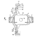
図1において,車両のミッションケース1内に差動装置Dが収容される。この差動装置Dは,デフケース2と,このデフケース2内に収容されるデフ機構3とよりなっている。デフケース2の右側部及び左側部には,同一軸線X上に並ぶ第1軸受ボス4及び第2軸受ボス5が一体に形成され,これら第1及び第2軸受ボス4,5は,軸受6,6′を介してミッションケース1に支持されると共に,右及び左車軸7,8を支持する。
In FIG. 1, a differential device D is accommodated in a
デフ機構3は,前記軸線Xと直交するようにしてデフケース2に保持されるピニオン軸9と,このピニオン軸9に支持される一対のピニオンギヤ10と,前記車軸7,8の内端にスプライン結合してピニオンギヤ10と噛合する一対のサイドギヤ11とより構成され,各ギヤの背面は,デフケース2の球状内面で回転自在に支承される。
The
ピニオン軸9は,デフケース2の外周部の一対の支孔12により保持される。デフケース2の外周部には,一方の支孔12と直交してその外周部を左右方向に貫通するピン孔13が設けられており,このピン孔13に圧入嵌合される抜け止めピン14がピニオン軸9を貫通することで,ピニオン軸9の支孔12からの抜け止めが果たされる。
The
またデフケース2には,その中心Cから第2軸受ボス5側にオフセットした中間部に環状のフランジ15が一体に形成され,このフランジ15に,変速装置の出力ギヤ16と噛合するリングギヤ17が取り付けられる。
The
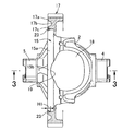
図2〜図4に示すように,さらにデフケース2の,前記軸線Xと直交する一直径線上で対向する周壁には,デフケース2の球状内面を加工すること,並びに前記デフ機構3のデフケース2への挿入を容易にすることのための一対の作業窓18が設けられる。これら作業窓18は,フランジ15に食い込むように大きく形成され,これよりフランジ15の第1軸受ボス4側の側面に凹部19が形成される。これに伴ないフランジ15は,前記凹部19が存在する一対の薄肉部15bと,前記凹部19が存在しない一対の厚肉部15aとを有することになる。
As shown in FIGS. 2 to 4, the spherical inner surface of the
図1及び図3に示すように,リングギヤ17は,外周にヘリカル状の歯群を有するリム17aと,このリム17aの内周面から突出する板状のスポーク17bと,このスポーク17bの内周端部の,第2軸受ボス5側の側面より突出する環状のハブ17cとよりなっており,スポーク17bには,ハブ17cの内周面側に突出する環状のストッパ壁22が一体に形成される。そしてハブ17cは,前記フランジ15に第1軸受ボス4側から圧入嵌合される。その際,ストッパ壁22がフランジ15の側面に当接することで,その圧入深さが規制される。
As shown in FIGS. 1 and 3, the
上記リングギヤ17において,スポーク17bの回転中心面P2は,前記フランジ15の回転中心面P1よりも第1軸受ボス4側に配置される。こうすることにより,リングギヤ17をデフケース2の中心Cに極力近づけて,リングギヤ17からデフケース2へのトルク伝達を良好にすることができる。またリングギヤ17に働くスラスト荷重及びラジアル荷重を,第1軸受ボス4をミッションケース1に支持させる軸受6と,第2軸受ボス5をミッションケース1に支持させる軸受6′とでバランス良く分担することができる。
In the
またミッションケース1内において,リングギヤ17と噛合すべき出力ギヤ16の左右方向位置は,変速装置の仕様に応じて変更される場合がある。本実施形態によれば,スポーク17bの回転中心面Pをデフケース2の中心Cに極力近づけているので,左右何れかの方向に出力ギヤ16の位置が変更される場合には,スポーク17bの位置を変更せずに,リム17aのみを出力ギヤ16に合わせて左右何れかの方向に延長すればよく,出力ギヤ16の仕様変更に柔軟に対応可能である。
In the
図4において,フランジ15及びハブ17cの圧入嵌合部には,その全周にわたり第2軸受ボス5側からレーザによる溶接23が施される。
In FIG. 4,
その溶接の際,前記ピン孔13を予め前記厚肉部15aの中央部に設けておき,そのピン孔13の中心を通るフランジ15の直径線Yにより,フランジ15及びハブ17cの圧入嵌合部を第1及び第2分割領域24,25に等分する。そして,一対のレーザトーチ26,26′を,これらが第1及び第2分割領域24,25の2つの分割点をそれぞれ狙うようにセットして,レーザトーチ26,26′又はデフケース2をフランジ15の中心軸周りに一定の方向へ回転しながら,第1及び第2分割領域24,25にレーザを照射することにより溶接23を施す。こうして,隣合う第1及び第2分割領域24,25の溶接開始点27と溶接終了点28とを,各厚肉部15aの中央部で一致させる。
At the time of welding, the
またその際,前記薄肉部15bに溶接23を施すときには,レーザ出力を,厚肉部15aの溶接時よりも低下させるか,あるいは溶接速度を厚肉部15aの溶接時よりも速めるかして,薄肉部15bの溶接深さH2(図3参照)を,厚肉部15aの溶接深さH1(図1参照)よりも浅くする。又は薄肉部15bでは溶接を行わない。
At that time, when the
次に,この実施形態の作用について説明する。 Next, the operation of this embodiment will be described.
リングギヤ17において,リム17aには,ハブ17cの内周面側に突出する環状のストッパ壁22を一体に形成し,ハブ17cをデフケース2のフランジ15に第1軸受ボス4側から圧入嵌合したとき,このストッパ壁22がフランジ15の側面に当接することで,圧入深さを規制し,フランジ15とリングギヤ17のハブ17cとの圧入嵌合部に第2軸受ボス5側からレーザによる溶接23を施すので,フランジ15及びハブ17cの圧入嵌合部の溶接を,フランジ15及びハブ17cの一側面側のみで行いながら,フランジ15及びハブ17cの結合強度を高めることができ,また溶接作業の能率を上げて製作コストの低減を図ることができる。しかも,溶接するフランジ15及びハブ17cの一側面側は,前記作業窓18と反対側であるので,溶接時に発生するスパッタが作業窓18からデフケース2内に侵入する心配もない。
In the
また上記圧入嵌合部に溶接23を施すに当たり,フランジ15の厚肉部15aとリングギヤ17とを所定の溶接深さH1をもって溶接し,フランジ15の薄肉部15bとリングギヤ17とは,前記所定の溶接深さH1より浅い溶接深さH2をもって溶接するか,もしくは全く溶接しないので,前記薄肉部15bでの貫通溶接を回避して,スパッタのデフケース2内への侵入を防ぐことができる。
Further, when performing
またフランジ15及びリングギヤ17の圧入嵌合部の溶接開始点27及び溶接終了点28を厚肉部15aで一致させたので,溶接開始点27及び溶接終了点28の一致により,その一致点において溶接深さが深くなっても,貫通溶接を回避することができる。
Further, since the welding start point 27 and the welding end point 28 of the press-fitting fitting portion of the
さらに前記フランジ15及びリングギヤ17の圧入嵌合部を,周方向に並ぶ複数の分割領域24,25に等分し,複数の分割領域24,25に同時に溶接23を施したので,溶接の各部位における冷却スピードの違いを極力抑えて溶接によるリングギヤ17の熱歪みの偏りを無くし,もしくは著しく少なくすることができ,これによりリングギヤ17の傾きを防ぐことができる。しかも各分割領域24,25の溶接開始点27と,それに隣接する分割領域24,25の溶接終了点28とを厚肉部15aで一致させたので,複数の二度打ち箇所によるフランジ15及びリングギヤ17の強度低下の影響を抑制することができ,且つ各一致点において貫通溶接を回避することができる。
Further, the press-fitting fitting portions of the
また前記デフ機構3のピニオン軸9の抜け止めピン14が嵌挿されるピン孔13を,これが前記厚肉部15aに対応する前記デフケース2の外周部を貫通するように設け,このピン孔13を基準にして前記溶接開始点27を設定したので,溶接開始点27は勿論,溶接終了点28も,必然的に厚肉部15aに設定されることになり,溶接開始点27の設定のための特別な目印を設けずとも,溶接を適正に行うことができる。
Further, a
またフランジ15及びストッパ壁22間には前記凹部19を残存しており,この凹部19は,前記圧入嵌合部の溶接時に発生するガスを外部に排出することを促すことに寄与する。
Further, the
尚,一致する溶接開始点27及び溶接終了点28と薄肉部15bとの間隔θは,フランジ15の中心軸線周りで45°以上に設定することが望ましい。即ち,厚肉部15aよりも薄肉部15bでのレーザ出力を低下させる場合,溶接開始点27から薄肉部15bまでの間に充分な間隔θを空けることにより,レーザ出力の開始直後よりも一層出力が安定した状態で,その出力を低下させることができる。その結果,レーザ出力の管理が容易となる。また溶接開始点27及び溶接終了点28が一致することによる溶接入熱の増加によって生じる薄肉部15bの熱歪みを抑制することができる。また溶接開始点27と溶接終了点28との一致点を薄肉部15bから周方向に離れた位置に設定することで,フランジ15及びリングギヤ17の強度低下を抑制することができる。
It should be noted that the interval θ between the matching welding start point 27 and welding end point 28 and the
出力ギヤ16及びリングギヤ17間でのトルク伝達中,ヘリカルギヤよりなるリングギヤ17には,左右方向のスラスト荷重が作用し,その右向きのスラスト荷重は,溶接23部分を介してフランジ15に支持され,左向きのスラスト荷重は,ストッパ壁22を介してフランジ15に支持されるので,溶接23部分の荷重負担を軽減することができる。
During torque transmission between the
本発明は,上記実施形態に限定されるものではなく,その要旨を逸脱しない範囲で種々の設計変更が可能である。例えば,上記実施形態では,圧入嵌合部を2つの分割領域に等分したが,3つ以上の分割領域に等分することもできる。 The present invention is not limited to the above embodiment, and various design changes can be made without departing from the scope of the invention. For example, in the above embodiment, the press-fitting portion is equally divided into two divided areas, but can be equally divided into three or more divided areas.
D・・・・差動装置
X・・・・軸線
2・・・・デフケース
3・・・・デフ機構
4・・・・第1軸受ボス
5・・・・第2軸受ボス
15・・・・フランジ
17・・・・リンクギヤ
17c・・・ハブ
18・・・・作業窓
19・・・・凹部
22・・・・ストッパ壁
23・・・・溶接
24,25・・・分割領域
D ... Differential gear X ...
Claims (3)
前記フランジ(15)に前記リングギヤ(17)のハブ(17c)を前記第1軸受ボス(4)側から圧入する工程と,これらフランジ(15)及びリングギヤ(17)の圧入嵌合部を,周方向に並ぶ複数の分割領域(24,25)に等分して,これら分割領域(24,25)を同時に溶接する工程とを含むことを特徴とする差動装置の製造方法。 First and second bearing bosses (4, 5) arranged on the same axis (X) are integrally formed on one side and the other side of the differential case (2) that accommodates the differential mechanism (3). An annular flange (15) is integrally formed at an intermediate portion offset from the center (C) of the differential case (2) toward the second bearing boss (5), and the axis (X) of the differential case (2) is further formed. A working window (18) for inserting the differential mechanism (3) is provided on a peripheral wall facing on a diameter line perpendicular to the flange, and the working window (18) bites into the flange (15) so that the flange A recess (19) is formed in the side surface of the first bearing boss (4) side of (15), and a ring gear (17) is press-fitted into the outer peripheral surface of the flange (15), and these flange (15) and ring gear (17) of the differential device in which the press-fitting fitting portion is welded A manufacturing method,
A step of press-fitting the hub (17c) of the ring gear (17) into the flange (15) from the first bearing boss (4) side, and a press-fitting fitting portion of the flange (15) and the ring gear (17) A step of equally dividing the plurality of divided regions (24, 25) arranged in the direction and welding the divided regions (24, 25) at the same time.
前記フランジ(15)への前記ハブ(17c)の圧入深さを一定に規制するために,前記ハブ(17c)の内周面に突設したストッパ壁(22)を前記フランジ(15)に当接させることを特徴とする差動装置の製造方法。 In the manufacturing method of the differential device of Claim 1,
In order to restrict the press-fitting depth of the hub (17c) to the flange (15), a stopper wall (22) protruding from the inner peripheral surface of the hub (17c) is contacted with the flange (15). A method of manufacturing a differential device, wherein the differential device is contacted.
前記フランジ(15)及び前記ストッパ壁(22)間には前記凹部(19)を残存させ,前記溶接時に発生するガスをこの凹部(19)を通して排出することを特徴とする差動装置の製造方法。 In the manufacturing method of the differential device of Claim 2,
A method of manufacturing a differential device, wherein the recess (19) is left between the flange (15) and the stopper wall (22), and gas generated during the welding is discharged through the recess (19). .
Priority Applications (6)
| Application Number | Priority Date | Filing Date | Title |
|---|---|---|---|
| JP2013271809A JP6189745B2 (en) | 2013-12-27 | 2013-12-27 | Manufacturing method of differential device |
| DE102014019879.0A DE102014019879B3 (en) | 2013-12-27 | 2014-12-19 | Differential case with mounting holes and welded ring gear |
| DE102014226644.0A DE102014226644B4 (en) | 2013-12-27 | 2014-12-19 | Process for simultaneous, segmental welding of a differential housing with a ring gear |
| US14/578,894 US9458919B2 (en) | 2013-12-27 | 2014-12-22 | Method of manufacturing differential device |
| CN201710805121.7A CN107676455B (en) | 2013-12-27 | 2014-12-23 | Differential gear |
| CN201410809440.1A CN104747695A (en) | 2013-12-27 | 2014-12-23 | Method of manufacturing differential device |
Applications Claiming Priority (1)
| Application Number | Priority Date | Filing Date | Title |
|---|---|---|---|
| JP2013271809A JP6189745B2 (en) | 2013-12-27 | 2013-12-27 | Manufacturing method of differential device |
Related Child Applications (1)
| Application Number | Title | Priority Date | Filing Date |
|---|---|---|---|
| JP2017149649A Division JP6457031B2 (en) | 2017-08-02 | 2017-08-02 | Differential |
Publications (2)
| Publication Number | Publication Date |
|---|---|
| JP2015124875A true JP2015124875A (en) | 2015-07-06 |
| JP6189745B2 JP6189745B2 (en) | 2017-08-30 |
Family
ID=53372314
Family Applications (1)
| Application Number | Title | Priority Date | Filing Date |
|---|---|---|---|
| JP2013271809A Active JP6189745B2 (en) | 2013-12-27 | 2013-12-27 | Manufacturing method of differential device |
Country Status (4)
| Country | Link |
|---|---|
| US (1) | US9458919B2 (en) |
| JP (1) | JP6189745B2 (en) |
| CN (2) | CN107676455B (en) |
| DE (2) | DE102014226644B4 (en) |
Cited By (1)
| Publication number | Priority date | Publication date | Assignee | Title |
|---|---|---|---|---|
| JP2017036780A (en) * | 2015-08-07 | 2017-02-16 | トヨタ自動車株式会社 | Differential device for vehicle |
Families Citing this family (7)
| Publication number | Priority date | Publication date | Assignee | Title |
|---|---|---|---|---|
| JP6501584B2 (en) | 2015-03-30 | 2019-04-17 | 武蔵精密工業株式会社 | Transmission |
| CN111051738B (en) * | 2017-08-31 | 2023-09-05 | 株式会社爱信 | Method for manufacturing differential device |
| JP6876592B2 (en) * | 2017-10-30 | 2021-05-26 | 武蔵精密工業株式会社 | Differential device |
| JP7082035B2 (en) * | 2018-11-27 | 2022-06-07 | 武蔵精密工業株式会社 | Differential device |
| JP7353827B2 (en) * | 2019-06-28 | 2023-10-02 | 武蔵精密工業株式会社 | transmission device |
| US11384830B2 (en) | 2019-08-06 | 2022-07-12 | Toyota Motor Engineering & Manufacturing North America, Inc. | Window design for a differential housing |
| CN112664636B (en) * | 2020-12-30 | 2022-09-23 | 一汽解放汽车有限公司 | Multi-spherical-surface interaxial differential assembly |
Citations (4)
| Publication number | Priority date | Publication date | Assignee | Title |
|---|---|---|---|---|
| JPS60231582A (en) * | 1984-04-28 | 1985-11-18 | Fujitsu Ltd | Laser welding method |
| JP2007192326A (en) * | 2006-01-19 | 2007-08-02 | Gkn ドライブライン トルクテクノロジー株式会社 | Motive power transmission device |
| JP2010032018A (en) * | 2008-07-30 | 2010-02-12 | Gkn ドライブライン トルクテクノロジー株式会社 | Differential case, its machining method, and differential device |
| JP2011089650A (en) * | 2011-02-10 | 2011-05-06 | Toyota Motor Corp | Differential device |
Family Cites Families (24)
| Publication number | Priority date | Publication date | Assignee | Title |
|---|---|---|---|---|
| JPS5166629A (en) * | 1974-12-02 | 1976-06-09 | Toyota Motor Co Ltd | |
| DE4313322C2 (en) | 1993-04-23 | 2001-08-02 | Porsche Ag | Differential for the final drive of a motor vehicle |
| DE10013429C5 (en) * | 2000-03-17 | 2009-10-01 | Daimler Ag | differential |
| EP1219865A1 (en) | 2000-12-29 | 2002-07-03 | Johann Hay GmbH & Co. KG, Automobiltechnik | A differential assembly and method for producing the same |
| JP2003001490A (en) | 2001-06-13 | 2003-01-08 | Denso Corp | Butt welding method |
| DE102004043337B4 (en) * | 2004-09-08 | 2007-07-12 | Daimlerchrysler Ag | Transverse differential of a motor vehicle and its manufacturing process |
| JP2007010040A (en) | 2005-06-30 | 2007-01-18 | Musashi Seimitsu Ind Co Ltd | Differential device |
| GB0601720D0 (en) * | 2006-01-27 | 2006-03-08 | Meritor Heavy Vehicle Sys Ltd | Differential Gear Assembly And Method |
| US20090266198A1 (en) * | 2008-04-29 | 2009-10-29 | Transform Automotive Llc | Laser welded differential casings for vehicle axles |
| JP5520494B2 (en) * | 2009-02-06 | 2014-06-11 | Gknドライブラインジャパン株式会社 | Differential device |
| JP5332937B2 (en) | 2009-06-19 | 2013-11-06 | トヨタ自動車株式会社 | Welding method between members |
| DE102009045424A1 (en) * | 2009-10-07 | 2011-04-14 | Zf Friedrichshafen Ag | Axle differential for motor vehicle, has crown gear provided in axial flange sided manner with ring-shaped axial web placed opposite to outer circumference of stop flange |
| JP5359813B2 (en) | 2009-11-24 | 2013-12-04 | トヨタ自動車株式会社 | Vehicle differential switching device |
| JP4902727B2 (en) * | 2009-12-22 | 2012-03-21 | アイシン・エーアイ株式会社 | Differential equipment |
| EP2527075B1 (en) * | 2010-01-22 | 2021-11-24 | Toyota Jidosha Kabushiki Kaisha | Welded structure and welding method |
| JP5345569B2 (en) * | 2010-02-03 | 2013-11-20 | 本田技研工業株式会社 | Vehicle differential |
| JP5509910B2 (en) | 2010-02-22 | 2014-06-04 | 日産自動車株式会社 | Beam welding member and differential device provided with the same |
| JP5327130B2 (en) | 2010-04-23 | 2013-10-30 | トヨタ自動車株式会社 | Ring gear welding method and welded structure |
| DE102010054655B4 (en) | 2010-09-15 | 2012-08-09 | Sona Blw Präzisionsschmiede Gmbh | Differential for motor vehicles |
| US20130195545A1 (en) * | 2010-09-20 | 2013-08-01 | Toyota Jidosha Kabushiki Kaisha | Welding structure |
| CN102179658B (en) * | 2011-02-28 | 2015-05-20 | 深圳市骏腾发自动焊接装备股份有限公司 | Welding method of automobile brake gear ring and device using method |
| CA2780125C (en) | 2011-06-22 | 2016-10-04 | Metal Forming & Coining Corporation | Flow-formed differential case assembly |
| US8876649B2 (en) | 2011-08-04 | 2014-11-04 | Toyota Jidosha Kabushiki Kaisha | Welding structure and method for manufacturing welding structure |
| DE102012004389B4 (en) | 2012-03-03 | 2022-02-10 | Daimler Ag | Differential gear for a motor vehicle as a welded construction with different materials |
-
2013
- 2013-12-27 JP JP2013271809A patent/JP6189745B2/en active Active
-
2014
- 2014-12-19 DE DE102014226644.0A patent/DE102014226644B4/en active Active
- 2014-12-19 DE DE102014019879.0A patent/DE102014019879B3/en active Active
- 2014-12-22 US US14/578,894 patent/US9458919B2/en active Active
- 2014-12-23 CN CN201710805121.7A patent/CN107676455B/en active Active
- 2014-12-23 CN CN201410809440.1A patent/CN104747695A/en active Pending
Patent Citations (4)
| Publication number | Priority date | Publication date | Assignee | Title |
|---|---|---|---|---|
| JPS60231582A (en) * | 1984-04-28 | 1985-11-18 | Fujitsu Ltd | Laser welding method |
| JP2007192326A (en) * | 2006-01-19 | 2007-08-02 | Gkn ドライブライン トルクテクノロジー株式会社 | Motive power transmission device |
| JP2010032018A (en) * | 2008-07-30 | 2010-02-12 | Gkn ドライブライン トルクテクノロジー株式会社 | Differential case, its machining method, and differential device |
| JP2011089650A (en) * | 2011-02-10 | 2011-05-06 | Toyota Motor Corp | Differential device |
Cited By (1)
| Publication number | Priority date | Publication date | Assignee | Title |
|---|---|---|---|---|
| JP2017036780A (en) * | 2015-08-07 | 2017-02-16 | トヨタ自動車株式会社 | Differential device for vehicle |
Also Published As
| Publication number | Publication date |
|---|---|
| CN107676455A (en) | 2018-02-09 |
| DE102014226644A1 (en) | 2015-07-02 |
| DE102014226644B4 (en) | 2022-02-17 |
| CN107676455B (en) | 2020-03-06 |
| DE102014019879B3 (en) | 2022-07-07 |
| US9458919B2 (en) | 2016-10-04 |
| JP6189745B2 (en) | 2017-08-30 |
| CN104747695A (en) | 2015-07-01 |
| US20150184734A1 (en) | 2015-07-02 |
Similar Documents
| Publication | Publication Date | Title |
|---|---|---|
| JP6217023B2 (en) | Differential device and manufacturing method thereof | |
| JP6189745B2 (en) | Manufacturing method of differential device | |
| JP2015124874A5 (en) | ||
| JP6196271B2 (en) | Welded structure and manufacturing method of welded structure | |
| EP3059472B1 (en) | Production method for fluid coupling and fluid coupling | |
| JP5206656B2 (en) | Differential gear device for vehicle | |
| JPWO2013018223A1 (en) | Welded structure and manufacturing method of welded structure | |
| JP6457031B2 (en) | Differential | |
| JP2016065582A (en) | Welding structure of differential device for vehicle | |
| US10415682B2 (en) | Differential case | |
| JP2010281419A (en) | Drive plate | |
| JP5627218B2 (en) | Differential gear device for vehicle | |
| JP2008208935A (en) | Tripod type constant velocity joint | |
| KR101668192B1 (en) | One-way keulleochiyong, inner race manufacture method of the assei | |
| JP2017198238A (en) | Differential gear case | |
| JP6467268B2 (en) | Planetary gear mechanism | |
| JP6187280B2 (en) | Differential gear device and manufacturing method thereof | |
| JP2020197238A (en) | Power transmission device | |
| JP2012189116A (en) | Member fixing structure | |
| JP2007071307A (en) | Uniform joint with torque transmission ring | |
| JP2017196708A (en) | Press-in jig | |
| JP2013103274A (en) | Electron beam welding method | |
| JP2015117741A (en) | Flange yoke |
Legal Events
| Date | Code | Title | Description |
|---|---|---|---|
| A621 | Written request for application examination |
Free format text: JAPANESE INTERMEDIATE CODE: A621 Effective date: 20160624 |
|
| A131 | Notification of reasons for refusal |
Free format text: JAPANESE INTERMEDIATE CODE: A131 Effective date: 20170405 |
|
| A521 | Request for written amendment filed |
Free format text: JAPANESE INTERMEDIATE CODE: A523 Effective date: 20170601 |
|
| TRDD | Decision of grant or rejection written | ||
| A01 | Written decision to grant a patent or to grant a registration (utility model) |
Free format text: JAPANESE INTERMEDIATE CODE: A01 Effective date: 20170705 |
|
| A61 | First payment of annual fees (during grant procedure) |
Free format text: JAPANESE INTERMEDIATE CODE: A61 Effective date: 20170803 |
|
| R150 | Certificate of patent or registration of utility model |
Ref document number: 6189745 Country of ref document: JP Free format text: JAPANESE INTERMEDIATE CODE: R150 |
|
| R250 | Receipt of annual fees |
Free format text: JAPANESE INTERMEDIATE CODE: R250 |
|
| R250 | Receipt of annual fees |
Free format text: JAPANESE INTERMEDIATE CODE: R250 |
|
| R250 | Receipt of annual fees |
Free format text: JAPANESE INTERMEDIATE CODE: R250 |
|
| R250 | Receipt of annual fees |
Free format text: JAPANESE INTERMEDIATE CODE: R250 |