JP2015123768A - Headrest and vehicle seat - Google Patents
Headrest and vehicle seat Download PDFInfo
- Publication number
- JP2015123768A JP2015123768A JP2013267481A JP2013267481A JP2015123768A JP 2015123768 A JP2015123768 A JP 2015123768A JP 2013267481 A JP2013267481 A JP 2013267481A JP 2013267481 A JP2013267481 A JP 2013267481A JP 2015123768 A JP2015123768 A JP 2015123768A
- Authority
- JP
- Japan
- Prior art keywords
- support
- headrest
- side support
- skin
- stay
- Prior art date
- Legal status (The legal status is an assumption and is not a legal conclusion. Google has not performed a legal analysis and makes no representation as to the accuracy of the status listed.)
- Pending
Links
- 239000006260 foam Substances 0.000 claims abstract description 43
- 238000005187 foaming Methods 0.000 claims abstract description 20
- 239000002994 raw material Substances 0.000 claims abstract description 15
- 210000000078 claw Anatomy 0.000 claims description 19
- 230000000149 penetrating effect Effects 0.000 claims 1
- 230000037431 insertion Effects 0.000 abstract 1
- 238000003780 insertion Methods 0.000 abstract 1
- 210000003491 skin Anatomy 0.000 description 69
- 239000002184 metal Substances 0.000 description 13
- 238000004519 manufacturing process Methods 0.000 description 7
- 239000000463 material Substances 0.000 description 6
- 238000009958 sewing Methods 0.000 description 6
- 238000010097 foam moulding Methods 0.000 description 4
- 230000002441 reversible effect Effects 0.000 description 4
- 229920005830 Polyurethane Foam Polymers 0.000 description 3
- 230000000694 effects Effects 0.000 description 3
- 239000004744 fabric Substances 0.000 description 3
- 239000010985 leather Substances 0.000 description 3
- 239000002649 leather substitute Substances 0.000 description 3
- 239000011496 polyurethane foam Substances 0.000 description 3
- 238000005452 bending Methods 0.000 description 2
- 230000002093 peripheral effect Effects 0.000 description 2
- 230000037303 wrinkles Effects 0.000 description 2
- 239000000470 constituent Substances 0.000 description 1
- 210000002615 epidermis Anatomy 0.000 description 1
- 238000000034 method Methods 0.000 description 1
- 238000012986 modification Methods 0.000 description 1
- 230000004048 modification Effects 0.000 description 1
- 230000003014 reinforcing effect Effects 0.000 description 1
- 229920005989 resin Polymers 0.000 description 1
- 239000011347 resin Substances 0.000 description 1
- 229920003002 synthetic resin Polymers 0.000 description 1
- 239000000057 synthetic resin Substances 0.000 description 1
Images

Landscapes
- Chair Legs, Seat Parts, And Backrests (AREA)
- Seats For Vehicles (AREA)
Abstract
Description
本発明は、ヘッドレスト及びこのヘッドレストが装着された車両用シートに関する。 The present invention relates to a headrest and a vehicle seat on which the headrest is mounted.
下記特許文献1にはヘッドレスト付き車両用シートが開示されている。この車両用シートのヘッドレストは、乗員の頭部を支持するヘッドレストパッドと、ヘッドレストパッドを支持するヘッドレスト保持部とを備えており、ヘッドレストパッドはヘッドレスト保持部に対して、シートバック前面のシート下方側にヘッドレストパッドを反転可能に支持することが可能となっている。
これにより、シートバック前面のシート下方側にヘッドレストパッドを配置すると、例えば、乗員の頸部とシートバックとの間にヘッドレストパッドを介在させることができ、乗員の頸部から頭部をリラックスした状態で支持することが出来る。
The following Patent Document 1 discloses a vehicle seat with a headrest. The headrest of the vehicle seat includes a headrest pad that supports the head of the occupant and a headrest holding portion that supports the headrest pad. The headrest pad is on the lower side of the seat back of the seat back with respect to the headrest holding portion. It is possible to support the headrest pad in a reversible manner.
Thereby, when the headrest pad is arranged on the seat lower side of the front surface of the seat back, for example, the headrest pad can be interposed between the occupant's neck and the seat back, and the head is relaxed from the occupant's neck Can be supported.
ところで、ヘッドレスト保持部は、ヘッドレストパッドの後方側に配置されるバックサポート部とバックサポート部の両側からシート前方側へ延びるサイドサポート部とが一体的に形成されており、上部から見た形状が略コ字状を呈して複雑な形状とされており、製造が容易とはいえず、改善の余地があった。 By the way, the headrest holding part is integrally formed with a back support part arranged on the rear side of the headrest pad and a side support part extending from both sides of the back support part to the front side of the seat, and the shape seen from above is substantially. It has a U shape and is a complicated shape, and it cannot be easily manufactured, and there is room for improvement.
本発明は、上記事実を考慮し、製造を容易にできるヘッドレスト、及び上記ヘッドレストがシートバックに装着された車両用シートを得ることが目的である。 An object of the present invention is to obtain a headrest that can be easily manufactured in consideration of the above facts, and a vehicle seat in which the headrest is mounted on a seat back.
請求項1に記載のヘッドレストは、シートバックに連結されるステー、前記ステーを覆うバックサポート表皮、前記ステーと前記バックサポート表皮との間に充填されるバックサポートクッション体、及び前記ステーに形成される係合部を有するバックサポートと、前記バックサポートの両側に配置されるサイドサポートフレーム、前記サイドサポートフレームを覆うサイドサポート表皮、前記サイドサポートフレームと前記サイドサポート表皮との間に充填されるサイドサポートクッション体、及び前記サイドサポートフレームに形成され前記係合部へ係合する被係合部を有するサイドサポートと、を有する。 The headrest according to claim 1 is formed in a stay connected to a seat back, a back support skin covering the stay, a back support cushion body filled between the stay and the back support skin, and the stay. A back support having an engaging portion, side support frames disposed on both sides of the back support, a side support skin covering the side support frame, a side support cushion body filled between the side support frame and the side support skin, and And a side support having an engaged portion that is formed on the side support frame and engages with the engaging portion.
請求項1に記載のヘッドレストは、バックサポートと、バックサポートの両側に配置されるサイドサポートの3つの部材を含んで構成されているので、各々の形状を単純化して単独で形成することができる。このため、バックサポートと左右のサイドサポートを一体化したものに比較して製造が容易になる。 Since the headrest according to the first aspect includes the three members of the back support and the side support arranged on both sides of the back support, each shape can be simplified and formed independently. For this reason, manufacture becomes easy compared with what integrated the back support and the left and right side supports.
さらに、バックサポートフレームの係合部とサイドサポートフレームの被係合部とを係合することで、バックサポートとサイドサポートとを容易に連結してヘッドレストを完成させることができる。 Furthermore, by engaging the engaging portion of the back support frame and the engaged portion of the side support frame, the back support and the side support can be easily connected to complete the headrest.
請求項2に記載の発明は、請求項1に記載のヘッドレストにおいて、前記係合部は前記ステーの側面を貫通するガイド孔を有し、前記被係合部は、前記ガイド孔に差し込まれるガイドピン、及び前記ステーを両側から挟持する挟持爪を備えている。 According to a second aspect of the present invention, in the headrest according to the first aspect, the engaging portion has a guide hole that penetrates a side surface of the stay, and the engaged portion is a guide that is inserted into the guide hole. A pin and a clamping claw for clamping the stay from both sides are provided.
請求項2に記載のヘッドレストでは、バックサポートのステーのガイド孔に向けてサイドサポートのガイドピンを挿入することで、バックサポートとサイドサポートとの位置決めを行うことができる。また、挟持爪でステーを径方向の両側から挟持することで、バックサポートとサイドサポートとが連結される。また、ガイドピンがガイド孔に挿入されるので、サイドサポートのステーの軸方向への移動は阻止される。 In the headrest according to the second aspect, the back support and the side support can be positioned by inserting the guide pins of the side support toward the guide holes of the stay of the back support. Further, the back support and the side support are connected by holding the stay from both sides in the radial direction with the holding claws. Further, since the guide pin is inserted into the guide hole, the side support stay is prevented from moving in the axial direction.
請求項3に記載の発明は、請求項1または請求項2に記載のヘッドレストにおいて、前記バックサポートは、前記バックサポート表皮に形成したバックサポートスリットに前記ステーを挿入し、前記バックサポート表皮の内側へ発泡原料を充填して発泡させることで前記バックサポートクッション体を形成しており、前記サイドサポートは、前記サイドサポート表皮に形成したサイドサポートスリットに前記サイドサポートフレームを挿入し、前記サイドサポート表皮の内側へ発泡原料を充填して発泡させることで前記サイドサポートクッション体を形成している。 According to a third aspect of the present invention, in the headrest according to the first or second aspect, the back support inserts the stay into a back support slit formed in the back support skin, and the inner side of the back support skin. The back support cushion body is formed by filling and foaming a foaming raw material, and the side support is inserted into the side support slit formed in the side support skin, and the foamed raw material inside the side support skin. The side support cushion body is formed by filling and foaming.
請求項3に記載のヘッドレストでは、バックサポートは、バックサポート表皮に形成したバックサポートスリットにステーを挿入し、バックサポート表皮の内側へ発泡原料を充填して発泡させることでバックサポートクッション体を形成している。バックサポートは、形状が単純化されているので、ステーもバックサポート表皮の内部に挿入する部分の形状を単純化できる。このため、バックサポート表皮に形成したバックサポートスリットを必要最小限の寸法としても、ステーをバックサポートスリットを介して表皮内へ容易に挿入することが出来る。 In the headrest according to claim 3, the back support forms a back support cushion body by inserting a stay into a back support slit formed in the back support skin, filling a foam raw material inside the back support skin, and foaming. doing. Since the shape of the back support is simplified, the shape of the portion of the stay that is inserted into the back support skin can also be simplified. For this reason, even if the back support slit formed in the back support skin is made the minimum necessary size, the stay can be easily inserted into the skin through the back support slit.
また、サイドサポートは、サイドサポート表皮に形成したサイドサポートスリットにサイドサポートフレームを挿入し、サイドサポート表皮の内部へ発泡原料を充填して発泡させることでサイドサポートクッション体を形成している。サイドサポートは、形状が単純化されているので、サイドサポートフレームの形状も単純化できる。このため、サイドサポート表皮に形成したサイドサポートスリットを必要最小限の寸法としても、サイドサポートフレームをサイドサポートスリットを介して表皮内へ容易に挿入することが出来る。 Further, the side support is formed by inserting a side support frame into a side support slit formed in the side support skin, filling the inside of the side support skin with foaming raw material, and foaming the side support cushion body. Since the shape of the side support is simplified, the shape of the side support frame can also be simplified. For this reason, even if the side support slit formed in the side support skin has the minimum required size, the side support frame can be easily inserted into the skin through the side support slit.
請求項4に記載の発明は、請求項1〜請求項3の何れか1項に記載のヘッドレストにおいて、乗員の頭部を支持可能な第1造形面を有すると共に、前記第1造形面とは反対側が乗員の頸部を支持可能な第2造形面とされ、前記バックサポートの前方側、かつ一対の前記サイドサポートの間に配置されるフロントヘッドレストフレーム、前記フロントヘッドレストフレームを覆うフロントヘッドレスト表皮、前記フロントヘッドレストフレームと前記フロントヘッドレスト表皮との間に充填されるフロントヘッドレストクッション体を有するフロントヘッドレストパッドと、一対の前記サイドサポートフレームと前記フロントヘッドレストフレームの両側部とを連結し、前記フロントヘッドレストパッドを前記サイドサポートに対して回転可能に支持する連結部と、を有する。 Invention of Claim 4 WHEREIN: While having a 1st modeling surface which can support a passenger | crew's head in the headrest of any one of Claims 1-3, what is the said 1st modeling surface? A front headrest frame that covers the front headrest frame, the front headrest frame disposed on the front side of the back support and between the pair of side supports, the second modeling surface having an opposite side capable of supporting the occupant's neck A front headrest pad having a front headrest cushion body filled between a front headrest frame and the front headrest epidermis, and a pair of the side support frames and both sides of the front headrest frame are connected, and the front headrest pad is Rotating with respect to the side support Having a connecting portion for supporting.
請求項4に記載のヘッドレストでは、フロントヘッドレストパッドが連結部でサイドサポートに対して回転可能に支持されている。このため、フロントヘッドレストパッドを回転させることで、乗員の頭部を支持可能な第1造形面、または乗員の頸部を支持可能な第2造形面の何れかを乗員側に向けることが出来る。 In the headrest according to the fourth aspect, the front headrest pad is rotatably supported with respect to the side support at the connecting portion. For this reason, by rotating the front headrest pad, either the first modeling surface that can support the head of the occupant or the second modeling surface that can support the neck of the occupant can be directed toward the occupant.
請求項5に記載の車両用シートは、請求項1〜請求項4に何れか1項に記載のヘッドレストと、前記シートバックに設けられ、前記ステーを軸方向に移動自在に支持して前記ヘッドレストの高さ方向の位置を調整可能なヘッドレストサポートと、を備えている。 The vehicle seat according to claim 5 is provided in the headrest according to any one of claims 1 to 4 and the seat back, and supports the stay movably in the axial direction. And a headrest support capable of adjusting the position in the height direction.
請求項5に記載の車両用シートでは、シートバックの上端部に設けられたヘッドレストサポートにヘッドレストのステーが支持されており、ヘッドレストをステーの軸方向に移動することで、ヘッドレストの高さ方向の位置を調整できる。このヘッドレストは、請求項1〜請求項4の何れか1項に記載されたものであるため、前述した如き請求項1〜請求項4の何れか1項に記載の作用効果を奏する。 In the vehicle seat according to claim 5, the headrest stay is supported by the headrest support provided at the upper end portion of the seat back, and the headrest is moved in the axial direction of the stay, thereby moving the headrest in the height direction. The position can be adjusted. Since the headrest is described in any one of claims 1 to 4, the headrest has the effects described in any one of claims 1 to 4.
以上説明したように、本発明に係るヘッドレスト及び車両用シートでは、製造を容易にすることができる。 As described above, the headrest and the vehicle seat according to the present invention can be easily manufactured.
以下、図1〜図10を参照して、本発明の実施形態に係るヘッドレスト14及び車両用シート10について説明する。なお、各図中に適宜示される矢印FR、矢印UP、矢印Wは、それぞれ車両用シートの前方向、上方向、幅方向を示している。また、本実施形態では、車両用シートの前方向、上方向、幅方向は、各々、車両用シートが搭載された車両の前方向、上方向、幅方向と略一致している。
Hereinafter, with reference to FIGS. 1-10, the
(車両用シートの構成)
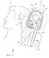
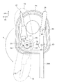
図1に示される本実施形態に係る車両用シート10は車両室内に設けられている。この車両用シート10は、運転席か助手席かを問わず、又フロントかリアかを問わない。また、車両用シート10は、シートバックの角度調整を行える可動式か、シートバックの角度調整を行えない固定式かを問わない。車両用シート10は、乗員Pが着座するシートクッション(図示省略)と、シートクッションのシート後端部に連結されて乗員の背凭れとなるシートバック12(上方側の一部を図示)と、シートバック12の上端部に連結されたヘッドレスト14とを備えている。
(Configuration of vehicle seat)
A
(ヘッドレストの構成)
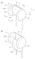
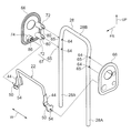
図1〜図3に示されるように、ヘッドレスト14は、フロントヘッドレストパッド16と、支持部材18とを備えており、フロントヘッドレストパッド16が後述する支持部材18のサイドサポート62に回転可能に連結されている。このフロントヘッドレストパッド16は、支持部材18に対して図2(A)に示される通常位置と図2(B)に示される反転位置との間で回転可能(図1の矢印R参照)とされている。
図1に示すように、このフロントヘッドレストパッド16の反転位置は、支持部材18の下方側で且つシートバック12の前面側に設定されており、乗員Pが必要とするときに、乗員Pの頸部をフロントヘッドレストパッド16によって支持可能な位置とされている。
(Headrest configuration)
As shown in FIGS. 1 to 3, the
As shown in FIG. 1, the reverse position of the
なお、乗員が必要とするときとは、運転者においては、好ましくは非走行時であって快適性やリラックスが必要な時という意味である。また、乗員が快適性を求める時とは、運転者以外の乗員においては、車両の走行時、非走行時を問わず快適性やリラックスが必要な時という意味である。以下、ヘッドレスト14の構成部材について順次詳細に説明する。
In addition, when a passenger | crew needs it, when a driver | operator is preferably non-running, it means when comfort and relaxation are required. In addition, when the occupant seeks comfort, it means that occupants other than the driver need comfort and relaxation regardless of whether the vehicle is traveling or not. Hereinafter, the constituent members of the
(フロントヘッドレストパッドの構成)
図4に示すように、フロントヘッドレストパッド16は、枕状のクッションであり、フロントヘッドレストフレーム22と、フロントヘッドレストフレーム22を覆ったフロントヘッドレスト発泡体(パッド)24と、フロントヘッドレスト発泡体24を覆ったフロントヘッドレスト表皮(カバー)26とによって構成されている。
(Configuration of front headrest pad)
As shown in FIG. 4, the
フロントヘッドレストフレーム22は、略逆U字状に形成された金属製のフレーム本体42、フレーム本体42の両側部に設けられる金属製のサポートブラケット44とを含んで構成されている。
サポートブラケット44は、金属板により略クランク状に形成されており、フレーム本体42の側部に沿って接合される接合部46と、接合部46の端部から接合部46と直交するヘッドレスト幅方向外側へ延びる延設部48と、延設部48の端部から延設部48と直交する方向へ延びるピン受け部50を備えている。なお、接合部46と延設部48には、補強用の金属板52が接合されている。
The
The
ピン受け部50は、後述するヒンジ軸86が挿入されるピン孔54が中央に形成されている。ピン受け部50の端部は、ピン孔54を曲率中心とした半円形に形成された半円部50Aとされている。ピン受け部50には、半円部50Aの一方の端部側に半円部50Aの径方向外側へ延びる第1のストッパ受け面56が形成され、半円部50Aの他方の端部側に半円部50Aの径方向外側へ延びる第2のストッパ受け面58が形成されている。
The
フロントヘッドレスト発泡体24は、例えばポリウレタンフォーム等のクッション性を有する発泡体からなり、フロントヘッドレストフレーム22及びフロントヘッドレスト表皮26と一体に発泡成形されている。フロントヘッドレストフレーム22は、フロントヘッドレスト発泡体24内に埋設されている。
図3(A)に示すように、フロントヘッドレストパッド16の幅方向両側には、ピン受け部50が露出しており、フロントヘッドレスト発泡体24には、半円部50Aの外周側に円弧状の凹部59が形成されている(図7参照)。この凹部59は、後述するストッパ84を逃がすためのものである。
The
As shown in FIG. 3A, the
フロントヘッドレスト表皮26は、例えば、布材、皮革又は合成皮革等の材料が縫製されることにより袋状に形成されており、フロントヘッドレスト発泡体24の表面を被覆している。このフロントヘッドレスト表皮26には、フロントヘッドレストフレーム22のピン受け部50、及び凹部59と対向する部位に円孔26Aが形成されており、ピン受け部50、及び凹部59は円孔26Aを介してフロントヘッドレスト表皮26の外側に突出(露出)している。
The
上記構成のフロントヘッドレストパッド16が製造される際には、フロントヘッドレストフレーム22に設けられたピン受け部50を図示しないシール部材によってシールすると共に、当該フロントヘッドレストフレーム22を袋状に形成されたフロントヘッドレスト表皮26の一部に設けられた直線状のスリット27(図3(B)参照)を介して内側に挿入する。そして、それら(フロントヘッドレストフレーム22及びフロントヘッドレスト表皮26)を発泡成形型の凹部(図示省略)にセットした状態で、フロントヘッドレスト発泡体24の材料である発泡原料をフロントヘッドレスト表皮26内に注入して発泡膨張させる。これにより、一体発泡成形によってフロントヘッドレストパッド16が製造される。
When the
図1、及び図2(A)に示すように、上記のように製造されたフロントヘッドレストパッド16は、その一面が乗員Pの頭部(後頭部)を支持するための頭部支持面(第1造形面)16Aとされている。この頭部支持面16Aは、緩やかな凸曲面状に形成されており、フロントヘッドレストパッド16が図2(A)に示される通常位置に位置する状態でシートバック前方側を向くように設けられている。また、図1、及び図2(B)に示すように、フロントヘッドレストパッド16は、頭部支持面16Aとは反対側の面が乗員Pの頸部を支持するための頸部支持面(第2造形面)16Bとされている。この頸部支持面16Bは、緩やかな凹曲面状に形成されており、フロントヘッドレストパッド16が反転位置に位置する状態でシートバック前方側を向くように設けられている。このフロントヘッドレストパッド16は、乗員Pの頸部を支持する部位(図1及び図2(B)では下側の部位)の厚さ寸法が他の部位に比べて厚く形成されている。
As shown in FIG. 1 and FIG. 2 (A), the
(支持部材の構成)
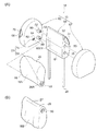
図3(A)に示すように、本実施形態の支持部材18は、バックサポート60と、バックサポート60の車両幅両側に配置されるサイドサポート62とを含んで構成されており、バックサポート60とサイドサポート62とは別体であり、別々に製造されている。
(Configuration of support member)
As shown in FIG. 3A, the
(バックサポート)
バックサポート60は、金属製のステー28と、ステー28の上部を覆うバックサポート発泡体(パッド)32と、バックサポート発泡体32を覆ったバックサポート表皮(カバー)34とを含んで構成されている。
(Back support)
The
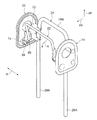
図5に示すように、ステー28は、例えば金属パイプまたは金属棒等の軸部材を曲げ加工することにより形成されたものである。このステー28は、シート前後方向から見て略逆U字状に形成されており、左右一対の脚部28Aと、一対の脚部28Aの上端部をシート幅方向に連結した基部28Bとによって構成されている。一対の脚部28Aは、図1に示すように、シートバック12の上端部に設けられた左右一対のヘッドレストサポート36にスライド可能に挿入される(なお、図1では、シート右側の脚部28A及びヘッドレストサポート36の図示が省略されている)。脚部28Aには、後述するガイドピン80を挿入するガイド孔64が形成されている。ヘッドレストサポート36は、シートバック12の骨格部材であるシートバックフレーム(図示省略)に固定されており、これにより、ステー28すなわちヘッドレスト14がシートバック12の上端部に連結されている。
なお、脚部28Aにおいて、ガイド孔64の形成されている軸部分65が本発明の係合部に相当している。
As shown in FIG. 5, the
In the
図3(A)に示すように、バックサポート発泡体32は、例えばポリウレタンフォーム等のクッション性を有する発泡体からなり、ステー28及びバックサポート表皮34と一体に発泡成形されている。ステー28は、上側の一部がバックサポート発泡体32内に埋設されている。
As shown in FIG. 3 (A), the
バックサポート表皮34は、例えば、布材、皮革又は合成皮革等の材料が縫製されることにより袋状に形成されており、バックサポート発泡体32の表面を被覆している。このバックサポート表皮34には、図3(A)に示すように、スリット61が形成されており、ステー28がスリット61を介してバックサポート表皮34の外側に突出している。
なお、バックサポート発泡体32の下側には、ステー28の一対の脚部28Aの下部が突出している。また、バックサポート表皮34、及びバックサポート発泡体32には、軸部分65が露出するように、開口35が形成されている。
The
Note that the lower portions of the pair of
上記構成のバックサポート60が製造される際には、ステー28の上部を袋状に形成されたバックサポート表皮34に形成した直線状のスリット61を介して内側に挿入する。そして、それら(ステー28、及びバックサポート表皮34)を発泡成形型の凹(図示省略)にセットした状態で、バックサポート発泡体32の材料である発泡原料をバックサポート表皮34内に注入して発泡膨張させる。これにより、一体発泡成形によってバックサポート60が製造される。
When the
(サイドサポートの構成)
図3(A)に示すように、フロントヘッドレストパッド16のシート右側に配置されるサイドサポート62とシート左側に配置されるサイドサポート62とは左右対称形状である。
図1に示すように、サイドサポート62は、乗員Pの頭部の側部を支持可能に配置されるクッションであり、図3(A)及び図5に示すように、サイドサポート62は、サイドサポートフレーム66と、サイドサポートフレーム66を覆ったサイドサポート発泡体(パッド)68と、サイドサポート発泡体68を覆ったサイドサポート表皮(カバー)70とを含んで構成されている。
(Side support configuration)
As shown in FIG. 3A, the
As shown in FIG. 1, the
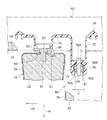
図6に示すように、本実施形態のサイドサポートフレーム66は、合成樹脂の成型品であり、シート上下方向、及び前後方向に沿った矩形平板状に形成されており、板厚方向がシート幅方向に沿う状態で配置されている。サイドサポートフレーム66には、後側に被係合部72が上下に形成され、前側の下側にボス74が形成されている。
As shown in FIG. 6, the
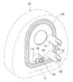
図7に示すように、被係合部72は、一部が中空とされた略円柱状とされ、先端にはステー28を挟持する一対の挟持爪76が形成されている。一方の挟持爪76と他方の挟持爪76との互いに対向する側部には、ステー28の外面に沿った円弧面76Aが形成されている。円弧面76Aの一端と他端との間隔寸法Tは、ステー28の直径Dよりも小さく設定されており、また、一方の挟持爪76、及び他方の挟持爪76には、円弧面76Aの端部から挟持爪76の先端に向けて傾斜面76Bが形成されており、一方の挟持爪76と他方の挟持爪76との間隔が、円弧面76Aの端部から挟持爪76の先端に向けて拡大している。
As shown in FIG. 7, the engaged
また、被係合部72には、挟持爪76と挟持爪76との間に、ステー28の脚部28Aに形成されたガイド孔64に挿入される金属製のガイドピン80が配置されている。ガイドピン80は、先端がテーパー状に形成されており、基部が被係合部72にインサートされている。
Further, a
図6〜8に示すように、ボス74は、一部が中空とされた略円柱状とされ、先端側には、ヒンジ金具82がインサートされている。
ヒンジ金具82は、金属板を曲げ加工することで形成され、ボス74の径方向に(ヘッドレストの前後方向)沿って配置され、後端がボス74の外周面から突出してボス74の軸方向先端側へ延びたストッパ84とされている。
As shown in FIGS. 6 to 8, the
The hinge fitting 82 is formed by bending a metal plate, and is disposed along the radial direction of the boss 74 (front and rear direction of the headrest). The rear end protrudes from the outer peripheral surface of the
ストッパ84の中央には、金属製のヒンジ軸86が固定されている。このヒンジ軸86は、フロントヘッドレストパッド16のピン受け部50に設けられたピン孔54に挿入されている。
A
本実施形態のサイドサポート62のサイドサポート発泡体68は、例えばポリウレタンフォーム等のクッション性を有する発泡体からなり、サイドサポートフレーム66及びサイドサポート表皮(カバー)70と一体に発泡成形されている。サイドサポートフレーム66は、サイドサポート発泡体68内に埋設されており、被係合部72の一部、及びボス74の端部がサイドサポート発泡体68の外側に露出している。
The
サイドサポート表皮70は、フロントヘッドレスト表皮26と同様に、例えば、布材、皮革又は合成皮革等の材料が縫製されることにより袋状に形成されており、サイドサポート発泡体68の表面を被覆している。図3(A)、及び図7に示すように、このサイドサポート表皮70には、サイドサポートフレーム66の被係合部72と対向する部位に円孔90が形成され、ボス74と対向する部位に円孔92が形成されており、被係合部72は円孔90を介し、ボス74は円孔92を介してサイドサポート表皮70の外側に突出(露出)している。
さらに、サイドサポート表皮70には、ストッパ84と対向する部位に矩形孔94(図8参照)が形成されており、ストッパ84は矩形孔94を介してサイドサポート表皮70の外側に突出(露出)している(図7参照)。
Similar to the
Further, the
上記構成のサイドサポート62が製造される際には、サイドサポートフレーム66を袋状に形成されたサイドサポート表皮70に設けられた直線状のスリット71(図6参照)を介して内側に挿入し、被係合部72をサイドサポート表皮70の円孔90に挿通させ、ボス74をサイドサポート表皮70の円孔92に挿通させ、ストッパ84をサイドサポート表皮70の矩形孔94に挿通させる。そして、それら(サイドサポートフレーム66及びサイドサポート表皮70)を発泡成形型の凹部(図示省略)にセットした状態で、サイドサポート発泡体68の材料である発泡原料をサイドサポート表皮70内に注入して発泡膨張させる。これにより、一体発泡成形によってサイドサポート62が製造される。
When the
バックサポート60は、フロントヘッドレストパッド16のシート幅方向の寸法と略同等の幅寸法を有し、フロントヘッドレストパッド16のシート上下方向の寸法と略同等の高さ寸法を有している。このバックサポート60の前面は、本体支持面60A1とされており、フロントヘッドレストパッド16が図2(A)に示す通常位置に位置する状態では、当該本体支持面60A1がフロントヘッドレストパッド16の頸部支持面16B(図2(A)では図示せず)と接触するようになっている。この状態では、フロントヘッドレストパッド16は、頸部支持面16Bをバックサポート60によってシートバック後方側から支持される。
The
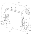
一対のサイドサポート62は、バックサポート60のシート幅方向両端部からシートバック前方側へ突出しており、フロントヘッドレストパッド16が図2(A)に示される通常位置に位置する状態では、一対のサイドサポート62によってフロントヘッドレストパッド16の左右両側面が覆われる。
一方、フロントヘッドレストパッド16が図2(B)に示される反転位置に位置する状態では、フロントヘッドレストパッド16の下部側がサイドサポート62よりも下方側へ突出すると共に、サイドサポート62の上部よりもシートバック前方側に突出するようになっている。
The pair of side supports 62 protrudes from the both ends in the seat width direction of the
On the other hand, in the state where the
図9に示すように、サイドサポートフレーム66のヒンジ軸86は、フロントヘッドレストフレーム22のピン受け部50に形成されたピン孔54に挿入されてフロントヘッドレストパッド16が回転可能(矢印R方向)とされており、図7に示すように、サイドサポートフレーム66のストッパ84が、フロントヘッドレストパッド16の凹部59に挿入されている。なお、凹部59は、ストッパ84に接触しない大きさに形成されている。
As shown in FIG. 9, the
図2(A)に示すように、フロントヘッドレストパッド16が通常位置にある状態では、図10の実線で示すように、ストッパ84に第1のストッパ受け面56が当接しており、通常位置よりも矢印R方向とは反対方向への回転を阻止している。
一方、図2(B)に示すように、フロントヘッドレストパッド16が反転位置にある状態では、図10の2点鎖線で示すように、ストッパ84に第2のストッパ受け面58が当接しており、反転位置よりも更に矢印R方向への回転を阻止している。
As shown in FIG. 2A, in the state where the
On the other hand, as shown in FIG. 2B, in the state where the
即ち、フロントヘッドレストパッド16の回転可能範囲は、ストッパ84に第1のストッパ受け面56が当接する位置と、ストッパ84に第2のストッパ受け面58が当接する位置との間に制限されている。
That is, the rotatable range of the
なお、フロントヘッドレストパッド16が通常位置に位置する状態では、前述したように、フロントヘッドレストパッド16が支持部材18によってシートバック後方側から支持され、また、フロントヘッドレストパッド16がサイドサポート62とサイドサポート62との間に嵌まり込むことにより、フロントヘッドレストパッド16が支持部材18に対して不用意にシートバック前方側へ回転しないようになっている。
In the state where the
一方、通常位置に位置するフロントヘッドレストパッド16の上部側を手動にてシートバック前方側へ引き出せば、フロントヘッドレストパッド16をヒンジ軸86回りに回転させて反転位置へと反転させることができる。
On the other hand, if the upper side of the
(作用及び効果)
次に、本実施形態のヘッドレスト14の組み立て手順、及び作用、効果について説明する。
本実施形態のヘッドレスト14は、フロントヘッドレストパッド16と支持部材18とを備え、支持部材18は、バックサポート60、サイドサポート62、及びサイドサポート62を含んで構成されている。
支持部材18は、上方から見て略コ字形状を呈しているが、図3(A)に示すように、バックサポート60、サイドサポート62、及びサイドサポート62の3部材を相互に組み付けることで構成されており、個々の部材は、例えば、コ字状のように屈曲していない単純なブロック形状とされている。
(Function and effect)
Next, the assembly procedure, operation, and effect of the
The
The
(フロントヘッドレストパッドの製造)
本実施形態では、フロントヘッドレストパッド16を製造する際、フロントヘッドレストフレーム22を袋状に形成されたフロントヘッドレスト表皮26に形成された直線形状とされたスリット27(図3参照)を介して内側に挿入するが、フロントヘッドレストパッド16は単純なブロック形状とされ、外側に設けられるフロントヘッドレスト表皮26も単純なブロック形状とされ、さらに、挿入するフロントヘッドレストフレーム22も単純な略U字形状とされているので、直線形状とされたスリット27を介して、フロントヘッドレストフレーム22をフロントヘッドレスト表皮26の内部に容易に挿入することができる。なお、スリット27の長さは、フロントヘッドレストフレーム22を挿入可能な最小限の長さに設定すればよい。また、スリット27は、発泡原料をフロントヘッドレスト表皮26内に注入して発泡膨張させた後、縫製により閉じることができる。
(Manufacture of front headrest pads)
In the present embodiment, when the
(バックサポートの製造)
本実施形態では、バックサポート60を製造する際は、ステー28を袋状に形成されたバックサポート表皮34に形成された直線形状とされたスリット61(図3参照)を介して内側に挿入するが、バックサポート60は単純なブロック形状とされ、外側に設けられるバックサポート表皮34も単純なブロック形状とされ、さらに、挿入するステー28も単純な略U字形状とされているので、直線形状とされたスリット61を介して、ステー28をバックサポート表皮34の内部に容易に挿入することができる。なお、スリット61の長さは、ステー28を挿入可能な最小限の長さに設定すればよい。また、スリット61は、発泡原料をバックサポート表皮34内に注入して発泡膨張させた後、縫製により閉じることができる。
(Manufacture of back support)
In the present embodiment, when the
(サイドサポートの製造)
本実施形態では、サイドサポート62を製造する際は、サイドサポートフレーム66を袋状に形成されたサイドサポート表皮70に形成された直線形状とされたスリット71(図7参照)を介して内側に挿入するが、サイドサポート62は単純なブロック形状とされ、外側に設けられるサイドサポート表皮70も単純なブロック形状とされ、さらに、挿入するサイドサポートフレーム66も比較的単純な平板形状とされているので、直線形状とされたスリット71を介して、サイドサポートフレーム66をサイドサポート表皮70の内部に容易に挿入することができる。なお、スリット71の長さは、サイドサポートフレーム66を挿入可能な最小限の長さに設定すればよい。また、スリット71は、発泡原料をサイドサポート表皮70内に注入して発泡膨張させた後、縫製により閉じることが出来る。
このように、フロントヘッドレストパッド16、バックサポート60、及びサイドサポート62は形状が単純化されているため製造し易くなっており(先行技術対比)、量産性を向上することができる。
(Manufacture of side support)
In the present embodiment, when the
Thus, since the
(ヘッドレストの組み立て)
本実施形態のヘッドレスト14は、上記のように製造されたフロントヘッドレストパッド16、バックサポート60、サイドサポート62、サイドサポート62を以下のようにして組み付けることで、簡単に完成させることが出来る。
(1) まず最初に、バックサポート60に、一方(例えば右側)のサイドサポート62を組み付ける。この組み付けは、サイドサポート62の被係合部72のガイドピン80がステー28のガイド孔64と同軸となるように対向させ、サイドサポート62の被係合部72をステー28の軸部分65に向けて押し込む。この押し込み操作により、被係合部72の挟持爪76の傾斜面76Bが軸部分65に押圧されて一方の挟持爪76と他方の挟持爪76が弾性変形して押し広がり、軸部分65が一対の挟持爪76によって挟持されると共に、ステー28のガイド孔64にガイドピン80が挿入され、バックサポート60に、サイドサポート62が組み付けられる。
なお、被係合部72の円弧面76Aの一端と他端との間隔寸法Tが、ステー28の直径Dよりも小さく設定されているため、軸部分65が一対の挟持爪76によって挟持されれば、一対の挟持爪76によってステー28が引っかかり、ステー28から被係合部72が外れることは抑えられる。
(Assembly of headrest)
The
(1) First, one side support 62 (for example, the right side) is assembled to the
Since the interval dimension T between one end and the other end of the
(2) 次に、一方のサイドサポート62のヒンジ軸86を、フロントヘッドレストパッド16のピン孔54に挿入し、バックサポート60の前面側にフロントヘッドレストパッド16を保持する。
(3) そして、他方のサイドサポート62を一方のサイドサポート62と同様にしてバックサポート60に組み付けると共に、他方のサイドサポート62のヒンジ軸86をフロントヘッドレストパッド16のピン孔54に挿入する。これにより、フロントヘッドレストパッド16、バックサポート60、サイドサポート62、及びサイドサポート62の組み付けが全て完了し、ヘッドレスト14が完成する。
このように、本実施形態のヘッドレスト14は、フロントヘッドレストパッド16、バックサポート60、サイドサポート62、及びサイドサポート62をボルトや工具等を用いることなく、差し込み作業のみで簡単に完成させることが出来る。
(2) Next, the
(3) Then, the
As described above, the
また、フロントヘッドレストパッド16、バックサポート60、サイドサポート62、及びサイドサポート62は、単純なブロック形状に形成されており、これらの製造も容易になっており、ヘッドレスト14の生産性を向上することが出来る。
なお、上記実施形態では、バックサポート60に右側のサイドサポート62を先に組み付けたが、バックサポート60に左側のサイドサポート62を先に組みつけても良い。
Further, the
In the above embodiment, the
(実施形態の補足説明)
上記実施形態では、例えば、バックサポート60は、ステー28の上部をバックサポート表皮34の内部に挿入して発泡金型にセットし、発泡原料をバックサポート表皮34内に注入して発泡膨張させて製造したが、本発明はこれに限らず、ステー28の上部を発泡金型の凹部にセットして発泡原料を凹部内に注入して発泡膨張させてステー28にバックサポート発泡体32を一体的に形成し、その後、バックサポート発泡体32をバックサポート表皮34に挿入してバックサポート60を製造することも出来る。バックサポート発泡体32、及びバックサポート表皮34は単純な形状であるため、バックサポート表皮34をバックサポート発泡体32の外面に皺を生じないようにフィットさせることが容易となる。
なお、フロントヘッドレストパッド16、及びサイドサポート62も単純な形状であり、バックサポート60と同様に製造することができ、表皮を発泡体の外面に皺を生じないようにフィットさせることが容易となる。
上記実施形態のバックサポート60では、バックサポート発泡体32の内部にステー28の上部が埋設されているのみであったが、ステー28と連結される、例えば、樹脂等で形成されたフレームが埋設されていても良い。
(Supplementary explanation of the embodiment)
In the above embodiment, for example, the
The
In the
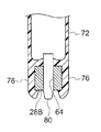
上記実施形態では、ステー28の断面形状が円形であったが、本発明はこれに限らず、ステー28の断面形状は、円形以外であっても良い。
図11には、断面形状が四角形の金属棒から形成したステー28を用いたヘッドレストの一部が断面図にて示されている。図11に示すように、この実施形態では、挟持爪76の側面形状が、ステー28の側面形状に沿って形成されており、挟持爪76が四角形のステー28の角部に引っ掛けられ、挟持爪76がステー28からより一層外れ難くなっている。なお、本実施形態では、ステー28を断面形状が四角形の金属棒から形成したが、円形の金属棒またはパイプの一部が断面四角形となるように切削加工またはプレス加工しても良い。
In the above embodiment, the cross-sectional shape of the
FIG. 11 is a sectional view showing a part of a headrest using a
その他、本発明は、その要旨を逸脱しない範囲で種々変更して実施できる。また、本発明の権利範囲が上記実施形態に限定されないことは勿論である。 In addition, the present invention can be implemented with various modifications without departing from the scope of the invention. It goes without saying that the scope of rights of the present invention is not limited to the above embodiment.
10 車両用シート
12 シートバック
14 ヘッドレスト
16 フロントヘッドレストパッド
16A 頭部支持面(第1造形面)
16B 頸部支持面(第2造形面)
22 フロントヘッドレストフレーム
24 フロントヘッドレスト発泡体(フロントヘッドレストクッション体)
26 フロントヘッドレスト表皮
28 ステー
32 バックサポート発泡体(バックサポートクッション体)
34 バックサポート表皮
36 ヘッドレストサポート
50 ピン受け部(連結部)
54 ピン孔(連結部)
60 バックサポート
61 スリット(バックサポートスリット)
62 サイドサポート
64 ガイド孔
65 軸部分(係合部)
66 サイドサポートフレーム
68 サイドサポート発泡体(サイドサポートクッション体)
70 サイドサポート表皮
71 スリット(サイドサポートスリット)
72 被係合部
76 挟持爪
80 ガイドピン
86 ヒンジ軸(連結部)
DESCRIPTION OF
16B Neck support surface (second modeling surface)
22
26
34
54 pin hole (connection part)
60
62
66
70
72 engaged
Claims (5)
前記バックサポートの両側に配置されるサイドサポートフレーム、前記サイドサポートフレームを覆うサイドサポート表皮、前記サイドサポートフレームと前記サイドサポート表皮との間に充填されるサイドサポートクッション体、及び前記サイドサポートフレームに形成され前記係合部へ係合する被係合部を有するサイドサポートと、
を有するヘッドレスト。 A stay connected to the seat back, a back support skin covering the stay, a back support cushion body filled between the stay and the back support skin, and a back support having an engaging portion formed on the stay; ,
Side support frames disposed on both sides of the back support, a side support skin covering the side support frame, a side support cushion body filled between the side support frame and the side support skin, and formed on the side support frame to the engaging portion A side support having an engaged portion to be engaged;
With headrest.
前記被係合部は、前記ガイド孔に差し込まれるガイドピン、及び前記ステーを両側から挟持する挟持爪を備えている、請求項1に記載のヘッドレスト。 The engaging portion has a guide hole penetrating the side surface of the stay,
The headrest according to claim 1, wherein the engaged portion includes a guide pin inserted into the guide hole and a clamping claw that clamps the stay from both sides.
前記サイドサポートは、前記サイドサポート表皮に形成したサイドサポートスリットに前記サイドサポートフレームを挿入し、前記サイドサポート表皮の内側へ発泡原料を充填して発泡させることで前記サイドサポートクッション体を形成している、請求項1または請求項2に記載のヘッドレスト。 The back support is formed by inserting the stay into a back support slit formed in the back support skin, filling the foam raw material inside the back support skin and foaming, and forming the back support cushion body.
The side support cushion body is formed by inserting the side support frame into a side support slit formed in the side support skin, filling a foaming raw material inside the side support skin, and foaming the foam. The headrest according to claim 2.
一対の前記サイドサポートフレームと前記フロントヘッドレストフレームの両側部とを連結し、前記フロントヘッドレストパッドを前記サイドサポートに対して回転可能に支持する連結部と、
を有する請求項1〜請求項3の何れか1項に記載のヘッドレスト。 While having a 1st modeling surface which can support a crew member's head, the side opposite to the 1st modeling surface is made into the 2nd modeling surface which can support a crew member's neck, the front side of the back support, and a pair of A front headrest frame disposed between the side supports, a front headrest skin covering the front headrest frame, a front headrest pad having a front headrest cushion body filled between the front headrest frame and the front headrest skin;
A connecting portion that connects the pair of side support frames and both side portions of the front headrest frame, and supports the front headrest pad rotatably with respect to the side support;
The headrest according to any one of claims 1 to 3, comprising:
前記シートバックに設けられ、前記ステーを軸方向に移動自在に支持して前記ヘッドレストの高さ方向の位置を調整可能なヘッドレストサポートと、
を備えた車両用シート。 The headrest according to any one of claims 1 to 4,
A headrest support provided on the seat back and capable of adjusting the position of the headrest in the height direction by supporting the stay movably in the axial direction;
Vehicle seat equipped with
Priority Applications (1)
| Application Number | Priority Date | Filing Date | Title |
|---|---|---|---|
| JP2013267481A JP2015123768A (en) | 2013-12-25 | 2013-12-25 | Headrest and vehicle seat |
Applications Claiming Priority (1)
| Application Number | Priority Date | Filing Date | Title |
|---|---|---|---|
| JP2013267481A JP2015123768A (en) | 2013-12-25 | 2013-12-25 | Headrest and vehicle seat |
Publications (1)
| Publication Number | Publication Date |
|---|---|
| JP2015123768A true JP2015123768A (en) | 2015-07-06 |
Family
ID=53534822
Family Applications (1)
| Application Number | Title | Priority Date | Filing Date |
|---|---|---|---|
| JP2013267481A Pending JP2015123768A (en) | 2013-12-25 | 2013-12-25 | Headrest and vehicle seat |
Country Status (1)
| Country | Link |
|---|---|
| JP (1) | JP2015123768A (en) |
Citations (3)
| Publication number | Priority date | Publication date | Assignee | Title |
|---|---|---|---|---|
| US5904405A (en) * | 1998-08-07 | 1999-05-18 | Wu; Frank | Pillow structure for chairs |
| JP2007282919A (en) * | 2006-04-18 | 2007-11-01 | Inoac Corp | Headrest skin and headrest |
| JP2013233829A (en) * | 2012-05-07 | 2013-11-21 | Nhk Spring Co Ltd | Headrest, and vehicle seat |
-
2013
- 2013-12-25 JP JP2013267481A patent/JP2015123768A/en active Pending
Patent Citations (3)
| Publication number | Priority date | Publication date | Assignee | Title |
|---|---|---|---|---|
| US5904405A (en) * | 1998-08-07 | 1999-05-18 | Wu; Frank | Pillow structure for chairs |
| JP2007282919A (en) * | 2006-04-18 | 2007-11-01 | Inoac Corp | Headrest skin and headrest |
| JP2013233829A (en) * | 2012-05-07 | 2013-11-21 | Nhk Spring Co Ltd | Headrest, and vehicle seat |
Similar Documents
| Publication | Publication Date | Title |
|---|---|---|
| AU2014355356B2 (en) | Vehicle Seat | |
| CN108116286B (en) | Seat device for vehicle | |
| KR101677890B1 (en) | Cushion element and method and tool for the production thereof | |
| JP6015492B2 (en) | Sheet component and manufacturing method thereof | |
| US9637034B2 (en) | Foam cord for seating foam stability and rigidity | |
| CN104870251B (en) | headrest | |
| JP2017019430A (en) | Vehicular seat | |
| JP5872376B2 (en) | Headrest and vehicle seat | |
| JP6455165B2 (en) | Headrest | |
| JP2015123768A (en) | Headrest and vehicle seat | |
| JP5687159B2 (en) | Armrest with soft cup holder for rear seats of automobiles | |
| JP2020127590A (en) | Seat pad, manufacturing method and molding die of the same | |
| JP7383301B2 (en) | Joint structure between headrest stay and core material and headrest | |
| KR101601554B1 (en) | Forming method for headrest by foaming | |
| JP5189319B2 (en) | Armrest with cup holder | |
| JP6847707B2 (en) | Vehicle seat pad | |
| JP2015154805A (en) | Vehicle seat | |
| JP4078587B2 (en) | Retractable headrest and its manufacturing method | |
| JP5983464B2 (en) | Manufacturing method of sheet components | |
| JP3773580B2 (en) | Automotive headrest | |
| JP5010315B2 (en) | Headrest and manufacturing method thereof | |
| JP5632601B2 (en) | Vehicle seat structure | |
| JP6152810B2 (en) | Vehicle seat | |
| JP5395645B2 (en) | Core for molding headrest | |
| JP6922496B2 (en) | Vehicle seat |
Legal Events
| Date | Code | Title | Description |
|---|---|---|---|
| A621 | Written request for application examination |
Free format text: JAPANESE INTERMEDIATE CODE: A621 Effective date: 20160610 |
|
| A977 | Report on retrieval |
Free format text: JAPANESE INTERMEDIATE CODE: A971007 Effective date: 20170313 |
|
| A131 | Notification of reasons for refusal |
Free format text: JAPANESE INTERMEDIATE CODE: A131 Effective date: 20170321 |
|
| A02 | Decision of refusal |
Free format text: JAPANESE INTERMEDIATE CODE: A02 Effective date: 20171003 |