JP2015114404A - Image stabilizer, optical equipment - Google Patents
Image stabilizer, optical equipment Download PDFInfo
- Publication number
- JP2015114404A JP2015114404A JP2013254747A JP2013254747A JP2015114404A JP 2015114404 A JP2015114404 A JP 2015114404A JP 2013254747 A JP2013254747 A JP 2013254747A JP 2013254747 A JP2013254747 A JP 2013254747A JP 2015114404 A JP2015114404 A JP 2015114404A
- Authority
- JP
- Japan
- Prior art keywords
- guide shaft
- shaft
- movable frame
- guide
- correction device
- Prior art date
- Legal status (The legal status is an assumption and is not a legal conclusion. Google has not performed a legal analysis and makes no representation as to the accuracy of the status listed.)
- Pending
Links
Images
Landscapes
- Adjustment Of Camera Lenses (AREA)
Abstract
【課題】可動枠の外形を大きくすることなく、可動枠の光軸と平行な軸周りの回転ブレを抑制するブレ補正装置、光学機器を提供する。【解決手段】ブレ補正装置6は、ブレを補正するレンズ群L3と、レンズ群L3を保持する可動枠30と、少なくとも2つの軸受部41a、41bが設けられ、主光学系の光軸に略直交する平面上において、可動枠30を移動可能に支持するベース枠40と、軸受部41a、41bに回転可能に係合する軸部材であって、その軸に沿った方向に移動可能なガイド軸50と、ガイド軸50に係合するガイド軸係合部61と、ガイド軸50に平行し、ガイド軸50とは別の軸周りで可動枠30と相対的に回転可能に係合する可動枠係合部62とを有したガイドアーム部材60とを備え、左軸受部41aは、ガイド軸係合部61の左係合部61aよりもガイド軸50の左端部側においてガイド軸50を係合すること、を特徴とする。【選択図】図2A blur correction device and an optical apparatus that suppress rotational blur around an axis parallel to the optical axis of a movable frame without increasing the outer shape of the movable frame. A blur correction device 6 includes a lens group L3 that corrects blur, a movable frame 30 that holds the lens group L3, and at least two bearing portions 41a and 41b. A base frame 40 that movably supports the movable frame 30 on an orthogonal plane, and a shaft member that rotatably engages the bearing portions 41a and 41b, and a guide shaft that is movable in a direction along the axis. 50, a guide shaft engaging portion 61 that engages with the guide shaft 50, and a movable frame that is parallel to the guide shaft 50 and that is rotatably engaged with the movable frame 30 around an axis different from the guide shaft 50. The left bearing portion 41 a engages the guide shaft 50 on the left end side of the guide shaft 50 with respect to the left engagement portion 61 a of the guide shaft engagement portion 61. It is characterized by doing. [Selection] Figure 2
Description
本発明は、ブレ補正装置、光学機器に関するものである。 The present invention relates to a shake correction apparatus and an optical apparatus.
従来、ブレ補正装置においては、可動部の光軸周りの回転ブレを抑制する技術が提案されている(例えば、特許文献1)。
特許文献1のブレ補正装置は、ベース枠と、撮像素子を載置した可動枠と、ベース枠に対して可動枠をガイドするガイド部材とを備え、可動枠に2つの軸受部が設けられており、ガイド部材に固定されたガイド軸を軸受部に係合させることによって、可動枠を光軸に垂直な面内に移動可能にしている。このようなブレ補正装置は、可動枠の光軸と平行な軸周りの回転ブレを抑制するために2つの軸受部の間隔を長くする必要があるが、この間隔を長くしようとした場合、可動枠の外形が大きくなってしまい、装置全体が大型化してしまう場合があった。
2. Description of the Related Art Conventionally, in a shake correction apparatus, a technique for suppressing rotational shake around the optical axis of a movable part has been proposed (for example, Patent Document 1).
The blur correction device of
本発明の課題は、可動枠の外形を大きくすることなく、可動枠の光軸と平行な軸周りの回転ブレを抑制するブレ補正装置、光学機器を提供することである。 An object of the present invention is to provide a blur correction device and an optical apparatus that suppress rotational blur around an axis parallel to the optical axis of the movable frame without increasing the outer shape of the movable frame.
前記課題を解決するために、第1の発明は、ブレを補正するブレ補正光学系と、前記ブレ補正光学系を保持する可動枠と、少なくとも2つの軸受部が設けられ、主光学系の光軸に略直交する平面上において、前記可動枠を移動可能に支持するベース枠と、前記軸受部に回転可能に係合する軸部材であって、その軸に沿った方向に移動可能なガイド軸と、前記ガイド軸に係合するガイド軸係合部と、前記ガイド軸に平行し、前記ガイド軸とは別の軸周りで前記可動枠と相対的に回転可能に係合する可動枠係合部とを有したガイドアーム部材とを備え、前記軸受部のうち少なくとも1つは、前記ガイド軸係合部よりも前記ガイド軸の端部側において前記ガイド軸を係合すること、を特徴とするブレ補正装置である。
第2の発明は、第1の発明のブレ補正装置において、前記ガイド軸は、前記ガイド軸係合部との係合部分に隣接して軸抜け防止部材が嵌合されていること、を特徴とするブレ補正装置である。
第3の発明は、第1の発明又は第2の発明のブレ補正装置において、前記ガイド軸は、その一端部において前記ガイド軸係合部と螺合されていること、を特徴とするブレ補正装置である。
In order to solve the above-mentioned problem, the first invention is provided with a blur correction optical system for correcting blur, a movable frame for holding the blur correction optical system, and at least two bearing portions, and the light of the main optical system. A base frame that movably supports the movable frame on a plane that is substantially orthogonal to the axis, and a shaft member that rotatably engages with the bearing portion, the guide shaft being movable in a direction along the axis A guide shaft engaging portion that engages with the guide shaft, and a movable frame engagement that is parallel to the guide shaft and that is rotatably engaged with the movable frame around an axis different from the guide shaft. And at least one of the bearing portions engages the guide shaft on the end side of the guide shaft with respect to the guide shaft engaging portion. This is a shake correction device.
According to a second aspect of the present invention, in the shake correction apparatus according to the first aspect of the invention, the guide shaft is fitted with a shaft slip-off prevention member adjacent to an engaging portion with the guide shaft engaging portion. This is a shake correction device.
According to a third aspect of the present invention, in the blur correction device according to the first or second aspect, the guide shaft is screwed into the guide shaft engaging portion at one end thereof. Device.
第4の発明は、第1の発明から第3の発明までのいずれかのブレ補正装置を備える光学機器である。 A fourth invention is an optical apparatus including any one of the shake correction apparatuses from the first invention to the third invention.
本発明によれば、可動枠を大きくすることなく、可動枠の光軸と平行な軸周りの回転ブレを抑制することができる。 According to the present invention, it is possible to suppress rotational vibration around an axis parallel to the optical axis of the movable frame without increasing the size of the movable frame.
(第1実施形態)
以下、図面を参照して、本発明に係るブレ補正装置及びこれを備えた光学機器の第1実施形態について説明する。本実施形態では、本発明に係るブレ補正装置を備えた光学機器として、デジタルカメラに装着されるレンズ鏡筒を例に挙げて説明する。
(First embodiment)
Hereinafter, with reference to the drawings, a blur correction device according to the present invention and an optical apparatus including the same will be described. In the present embodiment, a lens barrel attached to a digital camera will be described as an example of an optical apparatus including the shake correction apparatus according to the present invention.
なお、以下に示す図1には、説明と理解とを容易にするために、適宜にXYZの直交座標系を設けた。この座標系では、撮影者が光軸OAを水平として横長の画像を撮影する場合のカメラ位置(以下、正位置という)において撮影者から見て左側に向かう方向を+X方向とする。また、正位置において上側に向かう方向を+Y方向とする。更に、正位置において被写体に向かう方向を+Z方向とする。 In FIG. 1 shown below, an XYZ orthogonal coordinate system is provided as appropriate for ease of explanation and understanding. In this coordinate system, the direction toward the left side as viewed from the photographer at the camera position (hereinafter referred to as the normal position) when the photographer shoots a horizontally long image with the optical axis OA being horizontal is defined as the + X direction. Further, the direction toward the upper side at the normal position is defined as the + Y direction. Further, the direction toward the subject at the normal position is defined as the + Z direction.
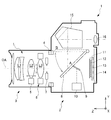
図1は、本実施形態のカメラの概略構成を示す断面図である。本実施形態のカメラ1は、レンズ交換式のデジタル一眼レフカメラである。カメラ1は、カメラ本体2と、レンズ鏡筒3とを備える。
レンズ鏡筒3は、マウント部4を介してカメラ本体2に装着されている。
マウント部4は、カメラ本体2に設けられたカメラ側マウント(符号略)と、レンズ鏡筒3に設けられたレンズ側マウント(符号略)とから構成される。マウント部4は、カメラ本体2とレンズ鏡筒3との間でデータを送受信するための電極(不図示)や、カメラ本体2からレンズ鏡筒3へ電力を送信するための電極(不図示)等を備える。
FIG. 1 is a cross-sectional view showing a schematic configuration of the camera of the present embodiment. The
The
The mount unit 4 includes a camera side mount (not shown) provided on the
レンズ鏡筒3は、レンズ光学系L、フォーカス用モータ5、ブレ補正装置6、絞りユニット7等を備える。
The
レンズ光学系Lは、複数のレンズ群L1〜L3により構成される。図示しない被写体からの光は、レンズ群L1〜L3及び絞りユニット7を経て、カメラ本体2へ被写体光として入射する。なお、図1では、レンズ光学系Lの構成を模式的に示している。
The lens optical system L includes a plurality of lens groups L1 to L3. Light from a subject (not shown) passes through the lens groups L1 to L3 and the
レンズ光学系Lのうち、レンズ群L2は、フォーカス用モータ5により光軸OAに沿って移動するフォーカス調整用光学系である。また、レンズ群L3は、ブレ補正装置6により光軸OAと略直交する方向、すなわち光軸OAと交差する面と平行な交差面方向に移動するブレ補正光学系である。ブレ補正装置6については、詳細を後述する。
フォーカス用モータ5及びブレ補正装置6の動作は、レンズ鏡筒3の内部に設けられたレンズCPU(不図示)により制御される。レンズCPUは、カメラ本体2に設けられたカメラCPU(不図示)との間でデータを送受信する。レンズCPUは、カメラCPUの指示に従って、フォーカス用モータ5及びブレ補正装置6の動作を制御する。
絞りユニット7は、複数の絞り羽根(不図示)を備える。絞りユニット7は、絞り羽根を光軸OA方向と略垂直な平面上で駆動させて、被写体光の通過する開口の面積を変化させることにより、被写体光の光量を調整する。
Among the lens optical systems L, the lens unit L2 is a focus adjustment optical system that is moved along the optical axis OA by the
The operations of the
The
カメラ本体2は、メインミラー8、サブミラー9、測距ユニット10、シャッタユニット11、光学フィルタ12、撮像素子13、液晶モニタ14、ペンタプリズム15、接眼光学系16等を備える。
図1に示すように、メインミラー8は、撮像前においては光軸OA上に位置する(ポジションA)。この場合、レンズ鏡筒3からカメラ本体2に入射した被写体光は、メインミラー8により上方へ導かれ、拡散スクリーン(不図示)に被写体像として結像する。メインミラー8は、その一部にハーフミラーが形成されている。このため、被写体光の一部は、メインミラー8においてサブミラー9で下方に反射され、測距ユニット10にも結像する。また、拡散スクリーンに結像した被写体光は、ペンタプリズム15へ入射する。
The
As shown in FIG. 1, the
ペンタプリズム15は、入射した被写体光を接眼光学系16へ導く。撮影者は、接眼光学系16を目視することにより、撮影前の被写体像を観察することができる。
また、ペンタプリズム15は、入射した被写体光の一部を測光ユニット(不図示)へ導く。測光ユニットは、被写体光の輝度情報を検出する。測光制御演算部(不図示)は、測光ユニットで検出された輝度情報に基づいて被写体輝度を算出する。また、測光制御演算部は、設定された撮像感度、レンズ情報、及び算出した被写体輝度等を用いて演算を行い、露出値(絞り値、シャッタースピード)を決定する。
The
The
一方、メインミラー8は、撮像時には上方へ回動して、図1に破線で示すように、光軸OAの外へ退避する(ポジションB)。レンズ鏡筒3からカメラ本体2に入射した被写体光は、シャッタユニット11、光学フィルタ12を介して撮影用の撮像素子13へ導かれる。
光学フィルタ12は、撮像素子13の撮像面において、不要な空間周波数成分を除去する部材である。
撮像素子13は、取り込んだ被写体光を信号電荷として蓄積し、画像情報に変換する。この画像情報は、画像制御部(不図示)により画像補正や補間処理等の画像処理が施された後、メモリ(不図示)に記憶される。
液晶モニタ14は、撮影された静止画像や動画像を表示する。また、液晶モニタ14は、撮影条件やカメラ操作に関する情報、並びに各種のメッセージ等を表示する。
On the other hand, the
The
The
The liquid crystal monitor 14 displays captured still images and moving images. The liquid crystal monitor 14 displays information regarding shooting conditions and camera operations, various messages, and the like.
次に、本実施形態のブレ補正装置6の詳細について説明する。
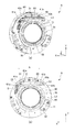
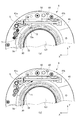
図2は、本実施形態のブレ補正装置の構成を説明する図である。図2(a)は、ブレ補正装置の斜視図である。図2(b)は、ブレ補正装置の平面図である。
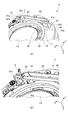
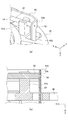
図3は、本実施形態のブレ補正装置のガイドアーム部材周辺を示す図である。図3(a)は、ブレ補正装置のガイドアーム部材の周囲を拡大した図である。図3(b)は、ガイドアーム部材の左端部周辺を拡大した図であり、ガイド軸から抜け防止部材が取り付けられる前の状態を示す図である。
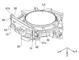
図4は、本実施形態のブレ補正装置の可動枠及びガイドアーム部材の構成を説明する斜視図である。
図5は、本実施形態のブレ補正装置のロックリング部材を説明する図である。図5(a)は、ロックリング部材によって可動枠がロックされた状態を示す図であり、図5(b)は、可動枠のロックが解除された状態を示す図である。
Next, details of the
FIG. 2 is a diagram illustrating the configuration of the shake correction apparatus according to the present embodiment. FIG. 2A is a perspective view of the shake correction apparatus. FIG. 2B is a plan view of the shake correction apparatus.
FIG. 3 is a view showing the periphery of the guide arm member of the shake correction apparatus of the present embodiment. FIG. 3A is an enlarged view of the periphery of the guide arm member of the shake correction apparatus. FIG. 3B is an enlarged view of the vicinity of the left end portion of the guide arm member, and shows a state before the slip prevention member is attached from the guide shaft.
FIG. 4 is a perspective view illustrating the configuration of the movable frame and the guide arm member of the shake correction apparatus of the present embodiment.
FIG. 5 is a view for explaining a lock ring member of the shake correction apparatus of the present embodiment. FIG. 5A is a diagram illustrating a state in which the movable frame is locked by the lock ring member, and FIG. 5B is a diagram illustrating a state in which the movable frame is unlocked.
図2及び図3に示すように、ブレ補正装置6は、可動枠30、ベース枠40、ガイド軸50、ガイドアーム部材60、ロックリング部材70等を備えている。
可動枠30は、中央にレンズ群L3が保持された枠体部材であり、ベース枠40に対して光軸に垂直な面内(XY面内)を移動する。可動枠30には、図4に示すように、ガイドアーム部材60と回転可能に係合する回転軸部31や、可動枠30の移動を制限する突起部32等が設けられている。可動枠30は、ベース枠40の撮像素子側とは反対側(+Z側、以下、表面側という)に配置されている。
回転軸部31は、ガイドアーム部材60の可動枠係合部62(後述する)に係合する軸部材である。回転軸部31は、可動枠30上に2つ設けられており、それぞれの軸方向が同一直線上に配置されている。
突起部32は、可動枠30に保持されたレンズ群L3の外周に形成された半円状の突起であり、ブレ補正動作を停止させる場合に、ベース枠40に設けられたロックリング部材70の突起当接部71(後述する)と当接する。本実施形態では、突起部32は、レンズ群L3の外周縁に等間隔で8つ設けられている。
As shown in FIGS. 2 and 3, the
The
The
The
ベース枠40は、図2及び図3に示すように、ガイドアーム部材60を介して可動枠30を光軸とは垂直な面内に移動可能に支持する部材である。ベース枠40は、その中央に被写体光が通過する通過孔が形成されている。ベース枠40には、軸受部41、アーム部材貫通孔42等が設けられている。
軸受部41は、ベース枠40の背面側(−Z側)に設けられ、ベース枠40とガイドアーム部材60とを回転可能に係合するガイド軸50を受ける軸受である。本実施形態では、軸受部41は、ガイド軸50の軸方向が左右方向(X方向)に平行になるように設けられており、ベース枠40の左上側に設けられる左軸受部41aと、右上側に設けられる右軸受部41bとから構成される。軸受部41は、ガイド軸50を軸周りで回転可能に係合するとともに、ガイド軸50を軸方向(X方向)に移動可能に係合する。
As shown in FIGS. 2 and 3, the
The bearing portion 41 is a bearing that is provided on the back side (−Z side) of the
左軸受部41aは、アーム部材貫通孔42の左貫通孔42a(後述する)の左側に配置されている。左軸受部41aは、U字状の溝が形成されており、その溝にガイド軸50の軸本体部51(後述する)の左端部近傍を係合する。
右軸受部41bは、アーム部材貫通孔42の右貫通孔42b(後述する)の左側に配置されている。右軸受部41bは、U字状の溝が形成されており、その溝にガイド軸50の軸本体部51(後述する)の右端部近傍を係合する。
The
The
アーム部材貫通孔42は、ベース枠40の背面側において上記軸受部41及びガイド軸50によって係合されるガイドアーム部材60を、ベース枠40の表面側に配置される可動枠30側に通過させる貫通孔である。本実施形態では、アーム部材貫通孔42は、ベース枠40上の左側に形成される左貫通孔42aと、右貫通孔42bとから構成される。この左貫通孔42a及び右貫通孔42bのそれぞれにガイドアーム部材60を通過させることにより、ガイドアーム部材60は、可動枠30とベース枠40とを最短距離で回転可能につなぐことができる。
The arm member through-hole 42 allows the
ガイド軸50は、ベース枠40に対してガイドアーム部材60をその軸周り及びその軸方向に移動させる軸部材である。ガイド軸50は、金属、例えば、ステンレスの棒材により形成されている。ガイド軸50は、軸本体部51、右側軸部52、溝53等から構成されている。
軸本体部51は、ベース枠40の軸受部41や、ガイドアーム部材60の左係合部61a(後述する)に係合する軸部分である。
右側軸部52は、ガイド軸50の右端部に設けられ、ガイドアーム部材60の右係合部61b(後述する)に係合する軸部分である。右側軸部52は、その外径が、軸本体部51の外径よりも細く形成されている。
溝53は、図3(b)に示すように、軸本体部51のガイドアーム部材60の左係合部61aが係合する位置よりも右側(−X側)に形成された溝であり、Eリングにより構成される軸抜け防止部材Eが着脱可能に取り付けられる。溝53は、軸抜け防止部材Eが取り付けられることによって、ガイドアーム部材60からガイド軸50が抜けてしまうのを防ぐことができる。
The
The shaft
The
As shown in FIG. 3B, the
ガイドアーム部材60は、光軸に垂直な面内(XY面内)において、可動枠30をベース枠40に対して移動可能にガイドする部材である。ガイドアーム部材60は、金属、例えば、ステンレスを板金等することにより形成される。ガイドアーム部材60には、図4に示すように、ガイド軸係合部61、可動枠係合部62等が設けられている。
ガイド軸係合部61は、ベース枠40の軸受部41に係合されるガイド軸50を係合する孔である。本実施形態では、ガイド軸係合部61は、左右方向に延在するガイド軸50の軸本体部51を係合する左係合部61aと、ガイド軸50の右側軸部52を係合する右係合部61bとから構成される。
The
The guide shaft engaging portion 61 is a hole for engaging the
左係合部61aは、ガイド軸50の軸本体部51に係合する孔であり、その孔径は、ガイド軸50の軸本体部51の外径に対応するようにして形成される。
右係合部61bは、ガイド軸50の右側軸部52に係合する孔であり、その孔径は、右側軸部52の外径に対応するようにして形成される。そのため、右係合部61bの孔径は、左係合部61aに比して小さい。
可動枠係合部62は、可動枠30の回転軸部31に係合する孔である。本実施形態では、可動枠係合部62は、図4に示すように、可動枠30に設けられた2つの回転軸部31に対応するようにして2つ形成されている。
The
The
The movable
以上の構成により、ブレ補正装置6は、ガイド軸50が、ガイドアーム部材60の左側から挿入されることによって、軸本体部51が左係合部61aに係合されるとともに、右側軸部52が右係合部61bに係合されることとなる。ここで、ガイド軸のガイドアーム部材への係合は、例えば、ガイドアーム部材に挟み込むようにしてガイド軸を係合する形態が考えられるが、この場合、ガイド軸の取り付けの際にガイドアーム部材を塑性変形させてしまうおそれがある。しかし、本実施形態では、上述のように、ガイド軸50をガイドアーム部材60の左側から挿入することによって、ガイドアーム部材60を変形させることなくガイド軸50を係合することができ、ブレ補正装置6の組立や分解の効率を向上させることができる。
With the above-described configuration, in the
また、ガイド軸50がガイドアーム部材60に挿入されると、ガイド軸50の溝53は、挿入された軸本体部51の左係合部61aよりも内側(−X側)に表出し、図3(b)に示すように、その表出した溝53に軸抜け防止部材Eが嵌合される。これにより、軸抜け防止部材Eは、接着剤等を使用することなく、ガイド軸50がガイドアーム部材60から抜けてしまうのを防ぐことができる。また、Eリングから構成される軸抜け防止部材Eが、溝53に嵌合される構成なので、ガイドアーム部材60に対するガイド軸50の組み付けや、分解を容易にすることができる。
When the
また、ガイドアーム部材60は、上述のように係合されたガイド軸50を、ベース枠40の軸受部41に係合することによって、ベース枠40に対してガイド軸50の軸周り(X軸周り)及び軸方向(X方向)に移動可能となる。ここで、左軸受部41a及び左係合部61a間と、右軸受部41b及び右係合部61b間とには、所定の隙間が形成されており、この隙間がガイドアーム部材60のX方向の移動ストロークとなる。
また、ガイドアーム部材60は、可動枠係合部62に可動枠30の回転軸部31が係合されることによって、可動枠30に対して回転軸部31の軸周り(X軸周り)に回転可能となる。
上述の可動枠30及びベース枠40に対するガイドアーム部材60の回転動作により、可動枠30は、ベース枠40に対してY方向に移動することができる。また、ベース枠40に対するガイドアーム部材60のガイド軸50の軸方向の移動によって、可動枠30は、ベース枠40に対してX方向に移動することができる。
Further, the
Further, the
The
ここで、軸受部41は、ガイド軸50を回転可能であって、ガイド軸50の軸方向に移動可能に係合するために、ガイド軸50との間に所定の微小隙間Bが形成されているので、可動枠30がベース枠40に対して光軸に平行な軸周りで回転してしまう、いわゆる回転ブレを生じる場合がある。この回転ブレのブレ量は、上述の微小隙間Bと2つの軸受部41a、41b間の距離A(図2(b)参照)との逆数(B/A)に比例する関係にある。そのため、この回転ブレは、微小隙間Bをより狭くするか、若しくは距離Aをより長くすることで、そのブレ量を抑制することができる。
Here, the bearing portion 41 is capable of rotating the
そこで、本実施形態のブレ補正装置6では、ベース枠40の右軸受部41bが、ガイドアーム部材60の右係合部61bよりも左側(+X側)でガイド軸50を係合している一方、左軸受部41aが、左係合部61aよりもガイド軸50の左端部側(+X側)でガイド軸50を係合している。そのため、ベース枠40は、左軸受部が左係合部よりも内側(−X側)に配置され、また、右軸受部が右係合部よりも内側(+X側)に配置される場合に比して、ガイド軸を係合する各軸受部の間隔Aを長くすることができる。これにより、ブレ補正装置6は、上述の可動枠30の回転ブレのブレ量を抑制することができる。
また、左軸受部41aがベース枠40の外周縁近傍であって左貫通孔42aの左側(+X側)に配置されるので、ブレ補正装置6は、ベース枠40に設けられた左貫通孔42aの周囲の強度を向上させることができる。
Therefore, in the
Further, since the
ロックリング部材70は、ブレ補正装置6のブレ補正動作を停止する場合に、ベース枠40に対する可動枠30の移動を制限するリング状の部材である。ロックリング部材70は、ベース枠40の被写体光が通過する通過孔の縁に設けられており、ベース枠40に対して、光軸を中心に回転可能に取り付けられている。ロックリング部材70には、突起当接部71、凹部72等が設けられている。
The
突起当接部71は、ロックリング部材70の内周縁に複数設けられた突起であり、本実施形態ではその内周縁に等間隔に8つ設けられている。この突起当接部71は、ロックリング部材70を回転させることによって、可動枠30に設けられた突起部32と当接する。ロックリング部材70は、図5(a)に示すように、この突起当接部71が可動枠30の突起部32と当接した場合、可動枠30の移動を制限するロック状態となる。一方、ロックリング部材70は、ロック状態からロックリング部材を時計回りに回転させることによって、図5(b)に示すように、突起当接部71が突起部32から離間した状態となり、可動枠30が光軸に垂直な面(XY平面)内を移動可能となるアンロック状態となる。
凹部72は、ロックリング部材70の外周縁に設けられた凹みであり、防振バネSの先端部が係合する。また、凹部72には、傾斜面72aが形成されており、係合する防振バネSの先端部が、凹部72の底部とロックリング部材70の外周縁との間の移動を容易にする。
The
The
この防振バネSは、その先端部がくの字状に形成された板バネであり、後端部がベース枠40に固定されている。防振バネSは、ロックリング部材70がロック状態の場合において、カメラ1内で生じる微振動等によってロックリング部材70が回転してしまい、アンロック状態に切り替わってしまうのを防止するために設けられている。具体的には、ロックリング部材70がロック状態の場合、図5(a)に示すように、防振バネSは、そのくノ字状の先端部が凹部72に係合し、ロックリング部材70の回転を制限する。一方、ロックリング部材70を回転させてロック状態からアンロック状態に変更した場合、図5(b)に示すように、防振バネSは、その先端部が、凹部72の傾斜面72aから滑り上がり、変形した状態でロックリング部材70の外周縁に移動する。
The anti-vibration spring S is a leaf spring whose tip is formed in a dogleg shape, and its rear end is fixed to the
この防振バネSは、ベース枠40上において、ロックリング部材70の外周縁近傍に配置する必要があり、また、ロックリング部材70の回転に伴い変形するため、その変形を見越した配置スペースの確保が必要となる。ここで、ベース枠の左軸受部が、ガイドアーム部材の左係合部よりも内側(−X側)に配置されている場合、防振バネSは、その先端部が左軸受部41aに干渉してしまう恐れがある。しかし、本実施形態のブレ補正装置6は、ベース枠40の左軸受部41aは、ガイドアーム部材60の左係合部61aよりもガイド軸50の左端部側(+X側)に配置されているので、上述の防振バネSの干渉を回避することができる。また、このような左軸受部41a及び左係合部61aの配置関係によって、ベース枠40上における防振バネSの配置についての設計の自由度を向上させることができる。
The anti-vibration spring S needs to be disposed on the
以上説明したように、本実施形態のブレ補正装置には以下のような効果がある。
(1)ブレ補正装置6は、ベース枠40の左軸受部41aが、ガイド軸係合部61の左係合部61aよりもガイド軸50の左端部側(+X側)においてガイド軸50を係合しているので、左軸受部が左係合部よりも内側(−X側)に配置される場合に比して、左右の軸受部の間隔A(図2(b)参照)を広くすることができる。これにより、ブレ補正装置6は、ベース枠40とガイド軸50とが係合される軸受部における光軸と平行な軸周りにおいて、可動枠30が回転してしまうのを抑制することができる。
また、ブレ補正装置6は、ベース枠40に軸受部41を設けているので、軸受部を可動枠に設ける場合に比して、可動枠30の外形を大きくすることなく、上述の可動枠30の回転を抑制することができる
(2)ブレ補正装置6は、ガイド軸50が、ガイド軸係合部61との係合部分に隣接して軸抜け防止部材Eが嵌合されているので、ガイドアーム部材60からガイド軸50が抜けてしまうのを防止することができる。
As described above, the blur correction device of the present embodiment has the following effects.
(1) In the
In addition, since the
(第2実施形態)
次に、本発明の第2実施形態について説明する。
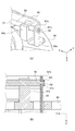
図6は、第2実施形態のブレ補正装置のガイドアーム部材の右係合部の詳細を説明する図である。図6(a)は、右係合部の詳細を示す斜視図であり、図6(b)は、ガイド軸の中心を通るXZ平面における図6(a)の断面図を示す。
図7は、第2実施形態のブレ補正装置のガイドアーム部材の右係合部の他の形態を説明する図である。図7(a)は、右係合部の詳細を示す斜視図であり、図7(b)は、ガイド軸の中心を通るXZ平面における図7(a)の断面図を示す。
なお、以下の説明及び図面において、前述した第1実施形態と同様の機能を果たす部分には、同一の符号又は末尾に同一の符号を付して、重複する説明を適宜省略する。
(Second Embodiment)
Next, a second embodiment of the present invention will be described.
FIG. 6 is a diagram illustrating details of the right engagement portion of the guide arm member of the shake correction apparatus according to the second embodiment. FIG. 6A is a perspective view showing details of the right engaging portion, and FIG. 6B is a cross-sectional view of FIG. 6A in the XZ plane passing through the center of the guide shaft.
FIG. 7 is a diagram illustrating another form of the right engagement portion of the guide arm member of the shake correction apparatus of the second embodiment. Fig.7 (a) is a perspective view which shows the detail of a right engaging part, FIG.7 (b) shows sectional drawing of Fig.7 (a) in the XZ plane which passes along the center of a guide shaft.
Note that, in the following description and drawings, the same reference numerals or the same reference numerals are given to the portions that perform the same functions as those in the first embodiment described above, and overlapping descriptions will be omitted as appropriate.
第2実施形態のブレ補正装置は、ガイド軸50の右側軸部52がガイドアーム部材60の右係合部61bと螺合されている点と、軸抜け防止部材Eが使用されていない点とで、第1実施形態のブレ補正装置と相違する。
ガイド軸50の右側軸部52は、図6に示すように、その外周側面にねじ溝52aが形成されている。
ガイドアーム部材60の右係合部61bは、その孔の内周面に、右側軸部52のねじ溝52aに対応するねじ溝が形成されている。
In the shake correction device of the second embodiment, the
As shown in FIG. 6, the
The
以上の構成により、本実施形態のブレ補正装置は、ガイド軸50の右側軸部52がガイドアーム部材60の右係合部61bに螺合する。これにより、ガイド軸50がガイドアーム部材60から抜けてしまうのを防止するとともに、軸抜け防止部材Eを省略することによってブレ補正装置6の部品点数を減らすことができる。
また、ガイドアーム部材60の右係合部61bは、図7に示すように、その孔部分にバーリング加工を施し、その孔の深さを深くして、ガイド軸50の右側軸部52と螺合する面積を増やすようにしてもよい。これにより、ブレ補正装置は、ガイド軸50と右係合部61bとをより強力に螺合することができる。また、ガイドアーム部材60の板厚が薄い場合であっても、ガイド軸50と右係合部61bとを互いに螺合することができる。
With the above-described configuration, in the shake correction device of the present embodiment, the
Further, as shown in FIG. 7, the
以上、本発明の実施形態について説明したが、本発明は前述した実施形態に限定されるものではなく、後述する変形形態のように種々の変形や変更が可能であって、それらも本発明の技術的範囲内である。また、実施形態に記載した効果は、本発明から生じる最も好適な効果を列挙したに過ぎず、本発明による効果は、実施形態に記載したものに限定されない。なお、前述した実施形態及び後述する変形形態は、適宜組み合わせて用いることもできるが、詳細な説明は省略する。 Although the embodiments of the present invention have been described above, the present invention is not limited to the above-described embodiments, and various modifications and changes can be made as in the modifications described later, and these are also included in the present invention. Within the technical scope. In addition, the effects described in the embodiments are merely a list of the most preferable effects resulting from the present invention, and the effects of the present invention are not limited to those described in the embodiments. It should be noted that the above-described embodiment and modifications described later can be used in appropriate combination, but detailed description thereof is omitted.
(変形形態)
(1)各実施形態において、ブレ補正装置6は、左軸受部41aが、ガイド軸係合部61の左係合部61aよりもガイド軸50の左端部側(+X側)に配置される例を示したが、これに限定されるものでない。例えば、右軸受部41bが、ガイド軸係合部61の右係合部61bよりもガイド軸50の右端部側(−X側)に配置されるようにしてもよい。
また、左軸受部41aだけでなく、右軸受部41bも、ガイド軸係合部61の右係合部61bよりもガイド軸50の右端部側(−X側)に配置される、すなわち、左右のそれぞれの係合部61a、61bの外側に、軸受部41a、41bがそれぞれ配置されるようにしてもよい。こうすることで、ガイド軸を係合する軸受部41の間隔A(図3(b)参照)をより広くすることができ、可動枠30の光軸な平行な軸周りの回転ブレのブレ量を更に抑制することができる。
この場合において、ガイド軸50の軸抜け防止に軸抜け防止部材Eを使用するとき、軸抜け防止部材Eは、左係合部61aの内側(−X側)と、右係合部61bの内側(+X側)とに配置するか、若しくは、左係合部61aの外側(+X側)と、右係合部61bの外側(−X側)とに配置する必要がある。なお、可動枠30のY方向の可動ストロークを確保する観点から、軸抜け防止部材Eの配置は、前者の配置の方がより望ましい。
(Deformation)
(1) In each embodiment, the
Further, not only the
In this case, when the shaft slip-off preventing member E is used to prevent the
(2)各実施形態において、ブレ補正装置6は、ガイド軸50の軸抜け防止に、軸抜け防止部材Eを使用したり、ガイド軸50の右側軸部52と右係合部61bとを螺号したりする例で説明したが、これに限定されるものでない。例えば、ガイド軸とガイドアーム部材とは、互いに接着されるようにしてもよい。
(3)各実施形態において、ブレ補正装置6は、軸受部41が2つ設けられる例で説明したが、これに限定されるものでなく、3つ以上設けられるようにしてもよい。
(2) In each embodiment, the
(3) In each embodiment, although the
1:カメラ、2:カメラ本体、3:レンズ鏡筒、6:ブレ補正装置、30:可動枠、31:回転軸部、40:ベース枠、41:軸受部、41a:左軸受部、41b:右軸受部、42:アーム部材貫通孔、50:ガイド軸、51:軸本体部、52:右側軸部、53:溝、60:ガイドアーム部材、61:ガイド軸係合部、61a:左係合部、61b:右係合部、62:可動枠係合部、70:ロックリング部材、E:軸抜け防止部材、L1〜L3:レンズ群 1: camera, 2: camera body, 3: lens barrel, 6: shake correction device, 30: movable frame, 31: rotating shaft, 40: base frame, 41: bearing, 41a: left bearing, 41b: Right bearing portion, 42: arm member through hole, 50: guide shaft, 51: shaft main body portion, 52: right shaft portion, 53: groove, 60: guide arm member, 61: guide shaft engaging portion, 61a: left engagement Joint part, 61b: Right engagement part, 62: Movable frame engagement part, 70: Lock ring member, E: Shaft slip prevention member, L1 to L3: Lens group
Claims (4)
前記ブレ補正光学系を保持する可動枠と、
少なくとも2つの軸受部が設けられ、主光学系の光軸に略直交する平面上において、前記可動枠を移動可能に支持するベース枠と、
前記軸受部に回転可能に係合する軸部材であって、その軸に沿った方向に移動可能なガイド軸と、
前記ガイド軸に係合するガイド軸係合部と、前記ガイド軸に平行し、前記ガイド軸とは別の軸周りで前記可動枠と相対的に回転可能に係合する可動枠係合部とを有したガイドアーム部材とを備え、
前記軸受部のうち少なくとも1つは、前記ガイド軸係合部よりも前記ガイド軸の端部側において前記ガイド軸を係合すること、
を特徴とするブレ補正装置。 An image stabilization optical system for correcting image blur,
A movable frame that holds the blur correction optical system;
A base frame that is provided with at least two bearing portions and that movably supports the movable frame on a plane substantially orthogonal to the optical axis of the main optical system;
A shaft member rotatably engaged with the bearing portion, and a guide shaft movable in a direction along the shaft;
A guide shaft engaging portion that engages with the guide shaft, and a movable frame engaging portion that is parallel to the guide shaft and is rotatably engaged with the movable frame around an axis different from the guide shaft. A guide arm member having
At least one of the bearing portions engages the guide shaft on the end side of the guide shaft with respect to the guide shaft engaging portion;
A blur correction device characterized by the above.
前記ガイド軸は、前記ガイド軸係合部との係合部分に隣接して軸抜け防止部材が嵌合されていること、
を特徴とするブレ補正装置。 The blur correction device according to claim 1,
The guide shaft is fitted with a shaft slip-off prevention member adjacent to an engaging portion with the guide shaft engaging portion,
A blur correction device characterized by the above.
前記ガイド軸は、その一端部において前記ガイド軸係合部と螺合されていること、
を特徴とするブレ補正装置。 The blur correction device according to claim 1 or 2,
The guide shaft is screwed with the guide shaft engaging portion at one end thereof;
A blur correction device characterized by the above.
Priority Applications (1)
| Application Number | Priority Date | Filing Date | Title |
|---|---|---|---|
| JP2013254747A JP2015114404A (en) | 2013-12-10 | 2013-12-10 | Image stabilizer, optical equipment |
Applications Claiming Priority (1)
| Application Number | Priority Date | Filing Date | Title |
|---|---|---|---|
| JP2013254747A JP2015114404A (en) | 2013-12-10 | 2013-12-10 | Image stabilizer, optical equipment |
Publications (1)
| Publication Number | Publication Date |
|---|---|
| JP2015114404A true JP2015114404A (en) | 2015-06-22 |
Family
ID=53528270
Family Applications (1)
| Application Number | Title | Priority Date | Filing Date |
|---|---|---|---|
| JP2013254747A Pending JP2015114404A (en) | 2013-12-10 | 2013-12-10 | Image stabilizer, optical equipment |
Country Status (1)
| Country | Link |
|---|---|
| JP (1) | JP2015114404A (en) |
-
2013
- 2013-12-10 JP JP2013254747A patent/JP2015114404A/en active Pending
Similar Documents
| Publication | Publication Date | Title |
|---|---|---|
| US10708502B2 (en) | Camera device and shake correction method | |
| JP2017122791A (en) | OPTICAL CONTROL DEVICE, OPTICAL DEVICE, AND OPTICAL CONTROL PROGRAM | |
| EP3483651B1 (en) | Imaging apparatus and interchangeable lens apparatus | |
| JP6775208B1 (en) | Imaging device and imaging system | |
| JP5293680B2 (en) | Lens barrel and imaging device including the same | |
| JP6381224B2 (en) | Lens apparatus and optical apparatus | |
| JP2011013255A (en) | Lens barrel | |
| US10310357B2 (en) | Optical apparatus including elastic damping member | |
| WO2020013200A1 (en) | Replacement lens and camera body | |
| JP5093036B2 (en) | Lens barrel and imaging device | |
| JP6662348B2 (en) | Lens barrel and imaging device | |
| JP2017161665A (en) | Optical apparatus having image blur correction device | |
| JP6136089B2 (en) | Lens barrel and imaging device | |
| JP2012132995A (en) | Alignment mechanism, lens barrel, and optical appliance | |
| WO2018198258A1 (en) | Lens barrel, camera body, camera system | |
| JP5593963B2 (en) | Vibration correction apparatus and optical apparatus | |
| JP2015203751A (en) | Lens barrel and imaging apparatus | |
| JP5895464B2 (en) | Lens barrel and imaging device | |
| JP2016080892A (en) | Image blur correction device, focus adjustment device, control unit, and optical apparatus | |
| JP2014089264A (en) | Optical vibration-proof device and optical apparatus | |
| JP4844312B2 (en) | Lens barrel, optical equipment | |
| JP2019159019A (en) | Lens device and imaging apparatus | |
| JP2017102203A (en) | Opening device and imaging apparatus | |
| JP2024018412A (en) | Image stabilization device and optical equipment | |
| JP2018077381A (en) | Lens barrel and imaging device |
Legal Events
| Date | Code | Title | Description |
|---|---|---|---|
| RD03 | Notification of appointment of power of attorney |
Free format text: JAPANESE INTERMEDIATE CODE: A7423 Effective date: 20161003 |
|
| RD04 | Notification of resignation of power of attorney |
Free format text: JAPANESE INTERMEDIATE CODE: A7424 Effective date: 20161003 |