JP6136089B2 - Lens barrel and imaging device - Google Patents
Lens barrel and imaging device Download PDFInfo
- Publication number
- JP6136089B2 JP6136089B2 JP2012051479A JP2012051479A JP6136089B2 JP 6136089 B2 JP6136089 B2 JP 6136089B2 JP 2012051479 A JP2012051479 A JP 2012051479A JP 2012051479 A JP2012051479 A JP 2012051479A JP 6136089 B2 JP6136089 B2 JP 6136089B2
- Authority
- JP
- Japan
- Prior art keywords
- guide bar
- lens barrel
- holding frame
- lens
- optical axis
- Prior art date
- Legal status (The legal status is an assumption and is not a legal conclusion. Google has not performed a legal analysis and makes no representation as to the accuracy of the status listed.)
- Active
Links
Images


Landscapes
- Lens Barrels (AREA)
Description
本発明は、レンズ鏡筒及び撮像装置に関するものである。 The present invention relates to a lens barrel and an imaging apparatus.
従来、ガイドバーで懸架されるレンズ群を備えるレンズ鏡筒がある(例えば、特許文献1参照)。 Conventionally, there is a lens barrel including a lens group suspended by a guide bar (for example, see Patent Document 1).
しかし、このようなレンズ鏡筒では、ガイドバーを保持する枠体に固定された固定レンズ群と、ガイドバーに懸架される可動レンズ群との間における相互の偏心が発生し、光学性能の低下を招いてしまう可能性がある。 However, in such a lens barrel, mutual decentration occurs between the fixed lens group fixed to the frame holding the guide bar and the movable lens group suspended on the guide bar, resulting in a decrease in optical performance. May be invited.
本発明の課題は、容易に光学調芯が可能なレンズ鏡筒及び撮像装置を提供することである。 An object of the present invention is to provide a lens barrel and an imaging apparatus that can easily perform optical alignment.
本発明のレンズ鏡筒は、第1光学部材を保持する第1保持枠に係合し、前記第1保持枠を前記第1光学部材の光軸方向に案内するガイドバーと、前記光軸方向に延びる基部と、前記基部から前記光軸と略直交する直交方向に突出して前記ガイドバーの一端を支持する第1支持部と、前記基部から前記直交方向に突出して前記ガイドバーの他端を前記ガイドバーの中心軸に対して偏心した円筒形状の偏心部材を介して支持する第2支持部と、を有するガイドバー保持部材と、第2光学部材を保持し、前記ガイドバーが挿通され、前記第1支持部に少なくとも一部が面接触されるとともに、前記ガイドバー保持部材に対する相対位置を固定される第2保持枠と、第3光学部材を保持し、前記第2支持部の前記偏心部材が設けられた部分よりも内周側に、少なくとも一部が接触して固定される第3保持枠と、を備え、前記光軸方向について、前記第2支持部と前記第3保持枠は、カメラ本体のカメラマウントと着脱可能に係合するレンズマウントと、前記第1保持枠との間に設けられている構成とした。 The lens barrel of the present invention is engaged with a first holding frame that holds the first optical member, guides the first holding frame in the optical axis direction of the first optical member, and the optical axis direction. A base extending to the base, a first support projecting from the base in an orthogonal direction substantially orthogonal to the optical axis, and supporting one end of the guide bar, and an other end of the guide bar projecting from the base in the orthogonal direction A guide bar holding member having a second support portion supported via a cylindrical eccentric member that is eccentric with respect to the central axis of the guide bar, holding the second optical member, and the guide bar is inserted, At least a portion of the first support portion is in surface contact with the second support frame, the relative position of the first support portion being fixed relative to the guide bar holding member, and the third optical member, and the eccentricity of the second support portion. Inner circumference than the part where the member is provided In, e Bei third holding frame is fixed at least partially in contact, and the direction of the optical axis, the third holding frame and the second support portion is detachably and camera mount of the camera body It was set as the structure provided between the lens mount to engage and the said 1st holding frame .
なお、上記構成は、適宜改良してもよく、また、少なくとも一部を他の構成物に代替してもよい。 In addition, the said structure may be improved suitably, and at least one part may substitute for another structure.
本発明によれば、容易に光学調芯が可能なレンズ鏡筒及び撮像装置を提供することができる。 According to the present invention, it is possible to provide a lens barrel and an imaging apparatus that can easily perform optical alignment.
以下、図面等を参照して、本発明の実施形態について説明する。
図1は、本発明に係る一実施形態であるカメラ1を概念的に示す図である。
なお、以下の各図には、説明と理解を容易にするために、XYZ直交座標系を設けた。この座標系では、撮影者が光軸OAを水平として横長の画像を撮影する場合のカメラの位置(以下、正位置という)において撮影者から見て左側に向かう方向をXプラス方向とし、正位置において上側に向かう方向をYプラス方向とする。また、正位置において被写体に向かう方向をZプラス方向とする。このZプラス方向を前面側、Zマイナス方向を背面側ともいう。さらに、光軸OA(すなわちZ軸)と平行な方向の移動を「直進」、光軸OAを中心とする回動を「回転」という。
Embodiments of the present invention will be described below with reference to the drawings.
FIG. 1 is a diagram conceptually showing a
In the following drawings, an XYZ orthogonal coordinate system is provided for ease of explanation and understanding. In this coordinate system, when the photographer shoots a horizontally long image with the optical axis OA being horizontal, the direction toward the left side when viewed from the photographer at the position of the camera (hereinafter referred to as a positive position) is the X plus direction. A direction toward the upper side in FIG. Also, the direction toward the subject at the normal position is the Z plus direction. The Z plus direction is also referred to as the front side, and the Z minus direction is also referred to as the back side. Furthermore, movement in a direction parallel to the optical axis OA (that is, the Z axis) is referred to as “straight forward”, and rotation about the optical axis OA is referred to as “rotation”.
カメラ1は、カメラ本体10と、レンズ鏡筒100と、によって構成されている。
レンズ鏡筒100は、焦点距離を可変調整可能ないわゆるズームレンズである。レンズ鏡筒100は、撮影光学系を構成する複数のレンズ群(L1〜L5)を備えている。
また、レンズ鏡筒100は、カメラマウントCMと着脱可能に係合するレンズマウントLMを備えており、このレンズマウントLMによってカメラ本体10に着脱可能に装着されるようになっている。
これにより、カメラ1は、用途に応じて異なるレンズ鏡筒100を交換して撮影することができるようになっている。このレンズ鏡筒100については、後に詳述する。
The
The
The
As a result, the
カメラ本体10は、クイックリターンミラー11、ファインダスクリーン12、ペンタプリズム13、接眼光学系14、シャッター15、撮像素子16、表示装置17及び制御装置18等を備えている。
クイックリターンミラー11は、レンズ鏡筒100によって集光された被写体像の光路を、ファインダスクリーン12に向けて屈曲させるためにカメラ本体10内に揺動可能に設けられたミラーである。クイックリターンミラー11は、レリーズ操作に応じて、被写体光の撮像素子16への入射を妨げない退避位置(図1中に二点鎖線で示す)に移動する。
The
The quick return mirror 11 is a mirror that is swingably provided in the
ファインダスクリーン12は、クイックリターンミラー11により反射された被写体像を結像させるスクリーンであり、クイックリターンミラー11とペンタプリズム13との間に配置されている。
ペンタプリズム13は、断面形状が五角形のプリズムであって、カメラ本体10を横位置に構えた状態の上部に配設されている。ペンタプリズム13は、ファインダスクリーン12に結像した像を正立像として接眼光学系14へと導く。
The
The
接眼光学系14は、ペンタプリズム13により正立像となった被写体像を、拡大観察するための光学系であり、ペンタプリズム13の背面側(撮影者側)に配置されている。
シャッター15は、レリーズ操作に応じて開閉し、撮像素子16に結像する被写体像光の露光時間を制御する。
The eyepiece
The
撮像素子16は、レンズ鏡筒100によって結像された被写体像を電気信号に変換する、たとえば、CCD等の光電変換素子である。撮像素子16は、カメラ本体10の内部の背面側(図1に示す右側)に、受光面を光軸OAに対して直交させた状態で設けられている。
表示装置17は、カメラ本体10の外側の背面側(撮影者側)に設けられた液晶等の表示パネルを備えている。表示装置17は、表示パネルに撮影画像や、露光時間等の撮影に関する情報等を表示する。
制御装置18は、CPU等を備えて構成され、前述した当該カメラ本体10の各構成要素およびレンズ鏡筒100を統括的に制御する。
The
The
The
カメラ本体10は、前述したようにレンズ鏡筒100が一体に結合されてカメラ1を構成する。結合状態では、カメラ本体10の制御装置18および図示しない電源が図示しない接続端子を介してレンズ鏡筒100と接続され、制御装置18によってレンズ鏡筒100における図示しない合焦モータや絞りユニット等を制御駆動するようになっている。
As described above, the
そして、カメラ1は、撮影時において下記のように作用する。
カメラ本体10が備える図示しないシャッターボタンが押圧操作(レリーズ操作)されると、クイックリターンミラー11が退避位置に移動する。シャッター15は、レリーズ操作に応じて開閉し、撮像素子16に被写体像光を所定時間露光させる。撮像素子16は、被写体像光を電気信号に変換して撮像する。撮像素子16によって撮像された撮像データは、図示しない記録部に記録され、これによって、撮影が行われる。
And the
When a shutter button (not shown) provided in the
つぎに、前述した図1に加えて図2〜図5を参照し、レンズ鏡筒100について詳細に説明する。
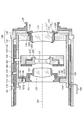
図2は、図1におけるレンズ鏡筒100の部分拡大断面図である。図3は、レンズ鏡筒100の図2とは異なる断面位置における部分拡大断面図である。図4は、第3レンズ群L3を保持する第3レンズ枠F3の外観斜視図である。図5は、偏心カラー150による第4レンズ群L4の調心機構を説明する概念図であって、(a)はガイドバー保持筒130部分の拡大断面図,(b)はその偏心カラー150を背面側から見た図である。
Next, the
FIG. 2 is a partially enlarged sectional view of the
レンズ鏡筒100は、前述したように焦点距離を可変調整可能なズームレンズである。固定鏡筒110の内部に、カム筒120と、ガイドバー保持筒130と、5群のレンズ群(L1〜L5)と、を備えている。レンズ鏡筒100は、背面側の端部に設けられたレンズマウントLMを介してカメラ本体10に装着される。
The
レンズ鏡筒100における焦点距離の変化(ズーミング)は、レンズ群(L1〜L5)の光軸OA方向の移動によって行われる。図1〜図3は、広角側端部を示し、望遠側では図示状態からレンズ群(L1〜L5)がそれぞれ所定量前面側に移動する。また、レンズ鏡筒100における結像位置の移動(焦点調節)は、第2レンズ群L2の光軸OA方向の移動によって行われる。さらに、レンズ鏡筒100は、手振れ等に起因する結像面における像移動を補正するブレ補正ユニット200を備えている。第4レンズ群L4はこのブレ補正ユニット200を構成するブレ補正光学系である。
The change (zooming) of the focal length in the
固定鏡筒110は、当該レンズ鏡筒100の外面を形成する外筒部111と、その内周側に同心状に位置する固定内筒112とが、基端部(背面側の端)で一体に構成されている。固定鏡筒110の背面側の端部には、レンズマウントLMが固定されている。
外筒部111の外周には、ピント操作環101と、ズーム操作環102とが、それぞれ回転可能に装着されている。
In the fixed
A
外筒部111と固定内筒112の間には、図示しない合焦モータや当該レンズ鏡筒100を制御するレンズ制御部を構成する制御基板等が収容される空間が形成されている。
図3に示すように、固定内筒112は、ガイドバー保持筒130の移動を案内する可動内筒直進溝113と、カム筒120を移動駆動するカム溝114と、を備えている。
Between the
As shown in FIG. 3, the fixed
カム筒120は、固定内筒112の内側に、回転および直進移動可能として配置されている。図3に示すように、カム筒120は、外周面に突設されたフォロアピン121と、光軸OAと平行に形成された直進操作溝122と、ガイドバー保持筒130を移動操作する内筒カム溝123と、ブレ補正ユニット200(第4レンズ群L4)を移動操作する4群カム溝124とを、備えている。
フォロアピン121は、固定内筒112に形成されたカム溝114に摺動移動可能に嵌合している。直進操作溝122には、ズーム操作環102に固定された操作キー104が固定内筒112を貫通して嵌合している。
これにより、カム筒120は、ピント操作環101の回転によって操作キー104を介して回転操作され、フォロアピン121が嵌合する固定内筒112のカム溝114の光軸OA方向における変位に従って直進移動する。
The
The
As a result, the
第1レンズ群L1と第2レンズ群L2は、それぞれ第1レンズ枠F1および第2レンズ枠F2に保持され、固定鏡筒110に直進移動可能に設けられている。第1レンズ枠F1および第2レンズ枠F2は、図示しない連繋機構を介してカム筒120と連繋しており、第1レンズ群L1と第2レンズ群L2はカム筒120の回転および直進に連動して直進するようになっている。
The first lens group L1 and the second lens group L2 are respectively held by the first lens frame F1 and the second lens frame F2, and are provided in the fixed
ガイドバー保持筒130は、略円筒状の部材であって、カム筒120の内側に回転および直進移動可能に配置されている。
ガイドバー保持筒130には、その前方側端部近傍に第3レンズ群L3が第3レンズ枠F3を介して固定され、背面側の端部に第5レンズ群L5が第5レンズ枠F5を介して固定されている。
The guide
The third lens group L3 is fixed to the guide
また、ガイドバー保持筒130の内部には、一対のガイドバー(メインガイドバー141およびサブガイドバー142)が光軸OAと平行に配設されている。これらのガイドバー141,142は、ブレ補正ユニット200(第4レンズ群L4)を直進移動可能に支持している。
すなわち、ガイドバー保持筒130は、第3レンズ群L3および第5レンズ群L5を固定保持すると共に、ガイドバー141,142で第4レンズ群L4(ブレ補正ユニット200)を直進移動可能に保持している。
In addition, a pair of guide bars (a
That is, the guide
ガイドバー保持筒130の外周面には、フォロアピン133が突設されている。フォロアピン133は、カム筒120に形成された内筒カム溝123に摺動移動可能に嵌合してこれを貫通し、その先端が固定内筒112の内周に形成された可動内筒直進溝113に摺動移動可能に嵌合している。
これにより、ガイドバー保持筒130は、カム筒120の回転および直進に伴って、可動内筒直進溝113に規定されつつ内筒カム溝123によって移動駆動されて、直進移動する。
A
Accordingly, the guide
ブレ補正ユニット200は、ベース枠210と、ブレ補正光学系である第4レンズ群L4を保持しベース枠210に対して光軸OAと直交する方向に移動可能な防振レンズ保持枠220と、を備え、全体の概略形状が所定厚さの円盤状に構成されている。また、ブレ補正ユニット200は、その外周に、ガイド軸受部230と、回り止め係合部240と、フォロアピン201と、を備えている。
The
ベース枠210は、所定厚さの円盤状であって、ガイド軸受部230、回り止め係合部240およびフォロアピン201は、このベース枠210の外周面に設けられている。
防振レンズ保持枠220は、所定厚さの円盤状であって、中央に第4レンズ群L4を保持している。
ベース枠210と防振レンズ保持枠220の間には、図示しない一対(X軸方向およびY軸方向)のボイスコイルモータが介設されており、このボイスコイルモータによって防振レンズ保持枠220はベース枠210に対して光軸OAと直交する方向に移動駆動されるようになっている。
The
The anti-vibration
A pair of voice coil motors (not shown) (X-axis direction and Y-axis direction) are interposed between the
ガイド軸受部230には、ガイドバー保持筒130におけるメインガイドバー141に所定の嵌合公差でガタ無く摺動移動可能に嵌合するスリーブ231が光軸OAと平行に圧入固定されている。
回り止め係合部240は、外側に開放するU字状の係合溝241を備えている。係合溝241の幅(対向面の間隔)は、サブガイドバー142が摺動移動可能に嵌るように設定されている。
フォロアピン201は、ブレ補正ユニット200の外周所定位置に突設されており、図3に示すように、ガイドバー保持筒130を貫通(遊嵌)し、その外周側に位置するカム筒120の4群カム溝124に摺動移動可能に嵌合している。
A
The
The
そして、ブレ補正ユニット200は、ガイド軸受部230のスリーブ231がメインガイドバー141に嵌合し、回り止め係合部240の係合溝241がサブガイドバー142に嵌合している。メインガイドバー141に案内されると共にサブガイドバー142によって回転が規制され、回転することなく直進移動可能としてガイドバー保持筒130に設けられている。
ブレ補正ユニット200は、カム筒120が回転および直進するとその4群カム溝124によってフォロアピン201が操作され、メインガイドバー141に沿って直進移動する。
すなわち、ブレ補正ユニット20は、ズーム操作環102の回転によるカム筒120の回転および直進によって直進移動するガイドバー保持筒130の内部を、ガイドバー保持筒130とは独立した異なる関係で回転することなく直進移動する。
In the
When the
That is, the shake correction unit 20 rotates the inside of the guide
上記のように構成されたレンズ鏡筒100は、固定鏡筒110における外筒部111に設けられたズーム操作環102が回転操作されると、操作キー104を介して回転操作されてカム筒120が回転しつつ直進する。
このカム筒120の回転および直進によって、第1レンズ枠F1(第1レンズ群L1),第2レンズ枠F2(第2レンズ群L2),ブレ補正ユニット200(第4レンズ群L4)およびガイドバー保持筒130(第3レンズ群L3と第5レンズ群L5)が、それぞれ所定の関係で直進して光軸OA方向に相対変位し、焦点距離の変更(ズーミング)が行われる。
ブレ補正ユニット200は、その保持する第4レンズ群L4を光軸OAと直交する面内で手振れ等に起因する結像面における像移動を相殺するように移動駆動し、像ブレを補正するように作用する。
The
By rotation and rectilinear movement of the
The
つぎに、ガイドバー保持筒130への、第3レンズ群L3(第3レンズ枠F3)、第5レンズ群L5(第5レンズ枠F5)、およびメインガイドバー141の装着構造について、詳細に説明する。
ガイドバー保持筒130は、前述したように、円筒状の部材であって、カム筒120の内側に摺動回転および光軸方向に摺動移動可能に嵌合配置されている。
ガイドバー保持筒130は、所定長さの円筒状の基筒部131と、この基筒部131の前面側近傍の内周に取り付けられた3群フランジ131Fと、背面側の端面に取り付けられた5群フランジ132を備える。そして、これらのフランジによって、ブレ補正ユニット200(第4レンズ群L4)を直進移動可能に支持する一対のガイドバー(メインガイドバー141およびサブガイドバー142)を保持している。
Next, the mounting structure of the third lens group L3 (third lens frame F3), the fifth lens group L5 (fifth lens frame F5), and the
As described above, the guide
The guide
3群フランジ131Fは、基筒部131の内周に、所定内径の円環状に突出形成されている。3群フランジ131Fは、光軸OA方向に所定の厚さを有している。その背面側の面は光軸OAと直交する3群装着面131Pとなっている。この3群装着面131Pには、第3レンズ枠F3を固定するための3群ネジ孔131Sがたとえば周方向に3箇所配設されている。
3群フランジ131Fの3群装着面131Pには、第3レンズ群L3を保持する第3レンズ枠F3が、3群ネジ孔131Sに螺合した3群固定ネジ134によって締着されている。この第3レンズ枠F3およびその装着構造については、後に詳述する。
The
A third lens frame F3 that holds the third lens group L3 is fastened to a third
5群フランジ132は、所定厚さの円環状である。5群フランジ132は、基筒部131の背面側の端面に、図示しない固定ネジによって締着されて一体に固定されている。
5群フランジ132の背面には、光軸OAと直交する5群装着面132Pが配設されている。この5群装着面132Pには、第5レンズ枠F5を固定するための5群固定ネジ孔132Sが配設されている。
5群フランジ132の5群装着面132Pには、第5レンズ群L5を保持する第5レンズ枠F5が、その5群固定ネジ孔132Sに螺合した5群固定ネジ135によって締着されている。この第5レンズ枠F5およびその装着構造については、後に詳述する。
The
On the back surface of the
A fifth lens frame F5 that holds the fifth lens group L5 is fastened to the fifth
メインガイドバー141およびサブガイドバー142は、それぞれ所定径の丸軸状の部材である。メインガイドバー141およびサブガイドバー142は、基筒部131の3群フランジ131Fと5群フランジ132とにそれぞれ端部が支持されて、ガイドバー保持筒130の内部の内周近傍に、光軸OAと平行に設けられている。メインガイドバー141とサブガイドバー142の配設位置は、周方向に所定量離間して設定されている。
The
メインガイドバー141とサブガイドバー142は、前面側の端部141A、142Aがそれぞれガイドバー保持筒130の3群フランジ131Fに形成されたガイドバー支持孔131Hに圧入固定されている。そしてメインガイドバー141の背面側の端部141Bは、偏心カラー150を介して5群フランジ132に支持されている。
The
偏心カラー150は、5群フランジ132に回転可能に装着され、メインガイドバー141における背面側の端部141Bを支持している。
図5に示すように、偏心カラー150は、基部151と小径部152の二段の外径を有する円柱状である。基部151側の端面には、メインガイドバー141がガタ無く摺動回転可能に嵌合するガイドバー支持孔153が、図5(b)に示すように、その中心軸から所定量:eだけ偏心した位置に所定深さに形成されている。また、小径部152側の端面には、所定幅で所定深さの操作スリット154が径方向に形成されている。
The
As shown in FIG. 5, the
偏心カラー150は、5群フランジ132の背面側に形成された調整支持孔132Aに、小径部152を背面側に向け、光軸OAと平行な軸回りにガタ無く摺動回転可能に嵌合している。偏心カラー150のガイドバー支持孔153には、メインガイドバー141の背面側の端部が摺動回転可能に嵌合している。これによって、偏心カラー150がメインガイドバー141の背面側の端部を支持している。
The
このような偏心カラー150によるメインガイドバー141の支持構造によれば、図5に示すように、操作スリット154をドライバー等によって操作して偏心カラー150を図5中矢印Rで示すように回転させると、偏心カラー150の回転中心から偏心したガイドバー支持孔153に支持されたメインガイドバー141の端部が、偏心量:eを半径として移動操作される。
その結果、メインガイドバー141は、ガイドバー保持筒130における3群フランジ131Fのガイドバー支持孔131Hによって支持された前端部を支点として(3群フランジ131Fの弾性変形によって)図5中矢印Sで示すように揺動し、光軸OAに対する角度が変化する。
According to the support structure of the
As a result, the
前述したように、メインガイドバー141は、ブレ補正ユニット200を支持してその移動を案内するものである。このため、当該メインガイドバー141の光軸OAに対する角度を変化させることで、ブレ補正ユニット200の保持する第4レンズ群L4が図5中矢印Tで示すように移動し、その光軸の当該レンズ鏡筒100の光軸OAに対して直交する方向(シフト方向)におけるズレを調整(調心)できる。
As described above, the
つぎに、基筒部131における3群フランジ131Fの3群装着面131Pへの第3レンズ枠F3の固定構造を説明する。
図4に示すように、第3レンズ枠F3は、第3レンズ群L3を保持する保持筒部161の外周に、所定厚さで所定径の円盤状の装着フランジ162を備えている。
装着フランジ162は、その前面を、保持筒部161が保持する第3レンズ群L3の光軸と直交する位置決め面163として形成されている。また、装着フランジ162は、メインガイドバー141およびサブガイドバー142と対応する位置に、それぞれ位置決め嵌合孔164と回り止め係合部165とを備えている。さらに、装着フランジ162には、ガイドバー保持筒130における3群フランジ131Fへの固定孔166が配設されている。
Next, a fixing structure of the third lens frame F3 to the third
As shown in FIG. 4, the third lens frame F3 includes a disc-shaped mounting
The front surface of the mounting
位置決め嵌合孔164は、ガイドバー保持筒130におけるメインガイドバー141に所定の嵌合公差でガタ無く摺動移動可能に嵌合するように形成されている。
回り止め係合部165は、外側に開放するU字状に形成され、その幅(対向面の間隔)は、サブガイドバー142が摺動移動可能に嵌るように設定されている。
The positioning
The
そして、第3レンズ枠F3は、位置決め嵌合孔164がメインガイドバー141に嵌合され、回り止め係合部165がサブガイドバー142に摺動移動可能に係合している。そして、位置決め面163と3群フランジ131Fの3群装着面131Pとを面接触させた状態で、固定孔166を介して3群フランジ131Fの3群ネジ孔131Sに3群固定ネジ134を螺合することによって3群フランジ131Fに固定されている。
なお、固定孔166の径は、光軸調整時における第3レンズ枠F3の光軸OAと直交する方向の移動を許容し得るように、3群固定ネジ134の径に対して所定量大きく設定されている。
In the third lens frame F3, the positioning
The diameter of the fixing
このようなガイドバー保持筒130における3群フランジ131Fへの第3レンズ枠F3の装着構造では、第3レンズ枠F3の光軸OAと直交する面に対する傾き(チルト)は、3群フランジ131Fの3群装着面131Pによって規定される。
一方、第3レンズ群L3の光軸OAと直交する方向における位置(シフト)は、メインガイドバー141の傾きによって規定される。
さらにガイドバー141に係合されるブレ補正ユニット200と装着フランジ162との偏心を少なくできる。
In such a structure for mounting the third lens frame F3 to the
On the other hand, the position (shift) of the third lens unit L3 in the direction orthogonal to the optical axis OA is defined by the inclination of the
Further, the eccentricity between the
このため、偏心カラー150の回転操作によるメインガイドバー141の角度調整によって第3レンズ群L3のシフト方向の調整を行う場合にチルトが発生しないので、調整が容易になる。
For this reason, when the shift direction of the third lens unit L3 is adjusted by adjusting the angle of the
つぎに、基筒部131における5群フランジ132の5群装着面132Pへの第5レンズ枠F5の固定構造を説明する。
第5レンズ枠F5は、第5レンズ群L5を保持する保持筒部171の外周に、所定厚さで所定径の円盤状の装着フランジ172を備えている。
装着フランジ172は、その前面を、保持筒部171が保持する第5レンズ群L5の光軸と直交する位置決め面173として形成されている。また、装着フランジ172には、5群フランジ132への固定孔174が配設されている。固定孔174は、5群固定ネジ135の外径に対して所定の調整クリアランスを有する径に設定されている。
Next, a structure for fixing the fifth lens frame F5 to the fifth
The fifth lens frame F5 includes a disc-shaped mounting
The front surface of the mounting
そして、第5レンズ枠F5は、その位置決め面173を5群フランジ132の5群装着面132Pに当接させ、固定孔174を介して5群フランジ132の5群固定ネジ孔132Sに螺合した5群固定ネジ135によって、5群フランジ132に固定されている。
この第5レンズ枠F5(第5レンズ群L5)の基筒部131における5群フランジ132への固定構造によれば、第5レンズ枠F5が保持する第5レンズ群L5の光軸OAに直交する面に対する傾きは、5群フランジ132の5群装着面132Pによって規定される。
また、第5レンズ群L5の光軸OAと直交する方向における位置(シフト)は、5群フランジ132に固定する5群固定ネジ135を緩めることで、5群固定ネジ135と固定孔174の間の調整クリアランスの範囲で調整することができる。
The fifth lens frame F5 has its
According to the fixing structure of the fifth lens frame F5 (fifth lens group L5) to the
Further, the position (shift) of the fifth lens unit L5 in the direction orthogonal to the optical axis OA is set between the fifth
上記のような、ガイドバー保持筒130への第3レンズ群L3(第3レンズ枠F3),第5レンズ群L5(第5レンズ枠F5)、およびメインガイドバー141の装着構造によれば、メインガイドバー141は、偏心カラー150の回転によって前端部を支点として揺動する。この揺動によって、その支持するブレ補正ユニット200における第4レンズ群L4を光軸OAと直交する方向に移動させて、当該レンズ鏡筒100の光軸OAと直交する方向における位置を調整(調心)できる。
According to the mounting structure of the third lens group L3 (third lens frame F3), the fifth lens group L5 (fifth lens frame F5), and the
第3レンズ群L3は、光軸OAと直交する面に対する傾きが3群フランジ131Fの3群装着面131Pによって規定され、光軸OAと直交する方向における位置はメインガイドバー141によって規定される。
これにより、偏心カラー150の回転操作によるメインガイドバー141の角度調整によって第4レンズ群L4の光軸調整(調心)を行っても、第3レンズ群L3の光軸と第4レンズ群L4の光軸との間に生ずるズレを抑制できる。
In the third lens unit L3, the inclination with respect to the surface orthogonal to the optical axis OA is defined by the third
Thus, even if the optical axis of the fourth lens unit L4 is adjusted (alignment) by adjusting the angle of the
また、第3レンズ群L3の光学軸に対してメインガイドバー141を調整すると、メインガイドバー141に支持された第4レンズ群L4は、光軸OAに対して直交する方向の移動(シフト)と同時に、光軸OAに直交する面に対する傾き(チルト)を生ずる。
本構成では、メインガイドバー141に対して第3レンズ群L3が位置決めされるため、シフトがゼロになる調整量と、チルトがゼロになる調整量の乖離が少ない。従って、より良好な光学性能調整結果を得られる。
Further, when the
In this configuration, since the third lens unit L3 is positioned with respect to the
なお、位置決め嵌合孔164および回り止め係合部165にはメインガイドバー141およびサブガイドバー142に対して若干のクリアランスが存在し、これは光軸OAと直交する方向における偏心の許容量に対し非常に小さい量である。
一方、第3レンズ群L3はメインガイドバー141の調心時における揺動支点近傍に位置するため、メインガイドバー141の揺動に対しする位置決め嵌合孔164のクリアランスは十分大きい。
The positioning
On the other hand, since the third lens unit L3 is located in the vicinity of the swing fulcrum when the
第5レンズ群L5は、光軸OAと直交する面に対する傾きが5群フランジ132の5群装着面132Pによって規定され、光軸OAと直交する方向における位置は5群固定ネジ135と固定孔174の間の調整クリアランスの範囲で調整することができる。
In the fifth lens unit L5, the inclination with respect to the surface orthogonal to the optical axis OA is defined by the fifth
そして、上記構成における、ガイドバー保持筒130が保持する第3レンズ群L3,第4レンズ群L4および第5レンズ群L5の光軸調整は、望遠側状態において、無限円の点光源を結像させ、結像点に発生するコマの方向と量を確認しながら、偏心カラー150を回転させ(メインガイドバー141を揺動させ)、コマが最小になる位置で偏心カラー150を固定する。
たとえば、5群フランジ132における調整支持孔132Aの内周と、偏心カラー150における小径部152の外周との間に接着剤を充填し、両者を固着させる。
The optical axis adjustment of the third lens unit L3, the fourth lens unit L4, and the fifth lens unit L5 held by the guide
For example, an adhesive is filled between the inner periphery of the
以上、本実施形態によると、以下の効果を有する。
(1)メインガイドバー141は、偏心カラー150の回転によって前端部を支点として揺動し、その支持するブレ補正ユニット200における第4レンズ群L4の光軸OAと直交する面に対する角度を調整することができる。
As described above, this embodiment has the following effects.
(1) The
(2)第3レンズ群L3は、光軸OAと直交する面に対する傾きが3群フランジ131Fの3群装着面131Pによって規定され、光軸OAと直交する方向における位置はメインガイドバー141によって規定される。これにより、偏心カラー150の回転操作によるメインガイドバー141の角度調整によって第4レンズ群L4の光軸調整(調心)を行っても、第3レンズ群L3の光軸と第4レンズ群L4の光軸との間に生ずるズレを抑制できる。その結果、第3レンズ群L3と第4レンズ群L4との偏心が少なく、光学性能の劣化を小さくできる。
また、第4レンズ群L4の光軸調整(調心)時において、シフトとチルトの相関が良く、調心の追い込みがし易い。
(2) In the third lens unit L3, the inclination with respect to the surface orthogonal to the optical axis OA is defined by the third
In addition, when the optical axis of the fourth lens unit L4 is adjusted (alignment), there is a good correlation between shift and tilt, and alignment is easy to follow.
(3)第5レンズ群L5は、光軸OAと直交する面に対する傾きが5群フランジ132の5群装着面132Pによって規定され、光軸OAと直交する方向における位置は5群固定ネジ135と固定孔174の間の調整クリアランスの範囲で調整することができる。
(3) In the fifth lens unit L5, the inclination with respect to the plane orthogonal to the optical axis OA is defined by the fifth
(変形形態)
本発明は、以上説明した実施形態に限定されることなく、以下に示すような種々の変形や変更が可能であり、それらも本発明の範囲内である。
(1)上記実施形態は、本発明を、メインガイドバー141によってブレ補正光学系である第4レンズ群L4を備えるブレ補正ユニット200が支持案内される構成に適用した。しかし、ガイドバーによって案内される光学系はブレ補正光学系に限らず、他の光学要素であっても良い。また、全体の光学系の構成も、本実施形態に限定されるものではない。
(Deformation)
The present invention is not limited to the embodiment described above, and various modifications and changes as shown below are possible, and these are also within the scope of the present invention.
(1) In the above-described embodiment, the present invention is applied to a configuration in which the
(2)上記実施形態では、メインガイドバー141が偏心カラー150によって揺動操作されてブレ補正ユニット200(第4レンズ群L4)の光軸調整を行うが、サブガイドバー142も同様に揺動操作して光軸調整を行うように構成しても良い。
(2) In the above embodiment, the
また、上記実施形態および変形形態は適宜に組み合わせて用いることができるが、各実施形態の構成は図示と説明により明らかであるため、詳細な説明を省略する。さらに、本発明は以上説明した実施形態によって限定されることはない。 Moreover, although the said embodiment and modification can be used in combination suitably, since the structure of each embodiment is clear by illustration and description, detailed description is abbreviate | omitted. Furthermore, the present invention is not limited by the embodiment described above.
1:カメラ、10:カメラ本体、16:撮像素子、100:レンズ鏡筒、130:ガイドバー保持筒、131:基筒部、131F:3群フランジ、131H:ガイドバー支持孔、131P:3群装着面、131S:3群ネジ孔、132:5群フランジ、132A:調整支持孔、132H:ガイドバー支持孔、132P:5群装着面、132S:5群固定ネジ孔、141:メインガイドバー、142:サブガイドバー、150:偏心カラー、153:ガイドバー支持孔、163:位置決め面、164:位置決め嵌合孔、165:回り止め係合部、166:固定孔、173:位置決め面、174:固定孔、200:ブレ補正ユニット、210:ベース枠、220:防振レンズ保持枠、230:ガイド軸受部、240:回り止め係合部、F3:第3レンズ枠、F5:第5レンズ枠 1: Camera, 10: Camera body, 16: Image sensor, 100: Lens barrel, 130: Guide bar holding tube, 131: Base tube, 131F: 3 group flange, 131H: Guide bar support hole, 131P: 3 group Mounting surface, 131S: 3rd group screw hole, 132: 5th group flange, 132A: Adjustment support hole, 132H: Guide bar support hole, 132P: 5th group mounting surface, 132S: 5th group fixing screw hole, 141: Main guide bar, 142: Sub guide bar, 150: Eccentric collar, 153: Guide bar support hole, 163: Positioning surface, 164: Positioning fitting hole, 165: Detent engagement portion, 166: Fixing hole, 173: Positioning surface, 174: Fixed hole, 200: blur correction unit, 210: base frame, 220: anti-vibration lens holding frame, 230: guide bearing portion, 240: anti-rotation engaging portion, F3: third Lens frame, F5: the fifth lens frame
Claims (9)
前記光軸方向に延びる基部と、前記基部から前記光軸と略直交する直交方向に突出して前記ガイドバーの一端を支持する第1支持部と、前記基部から前記直交方向に突出して前記ガイドバーの他端を前記ガイドバーの中心軸に対して偏心した円筒形状の偏心部材を介して支持する第2支持部と、を有するガイドバー保持部材と、
第2光学部材を保持し、前記ガイドバーが挿通され、前記第1支持部に少なくとも一部が面接触されるとともに、前記ガイドバー保持部材に対する相対位置を固定される第2保持枠と、
第3光学部材を保持し、前記第2支持部の前記偏心部材が設けられた部分よりも内周側に、少なくとも一部が接触して固定される第3保持枠と、
を備え、
前記光軸方向について、前記第2支持部と前記第3保持枠は、カメラ本体のカメラマウントと着脱可能に係合するレンズマウントと、前記第1保持枠との間に設けられていること、
を特徴とするレンズ鏡筒。 A guide bar that engages with a first holding frame that holds the first optical member and guides the first holding frame in the optical axis direction of the first optical member;
A base portion extending in the optical axis direction; a first support portion protruding from the base portion in an orthogonal direction substantially orthogonal to the optical axis to support one end of the guide bar; and a guide bar protruding from the base portion in the orthogonal direction. A second support part that supports the other end of the guide bar via a cylindrical eccentric member that is eccentric with respect to the central axis of the guide bar, and a guide bar holding member having
A second holding frame that holds the second optical member, the guide bar is inserted, at least a part of which is in surface contact with the first support portion, and a relative position with respect to the guide bar holding member is fixed;
A third holding frame that holds the third optical member and is fixed at least partially in contact with the inner peripheral side of the portion of the second support portion where the eccentric member is provided;
Bei to give a,
With respect to the optical axis direction, the second support portion and the third holding frame are provided between a lens mount that is detachably engaged with a camera mount of a camera body, and the first holding frame ,
A lens barrel characterized by
前記第1支持部の前記第2保持枠が面接触される面は、前記ガイドバーの前記他端側を向いた面であることを特徴とするレンズ鏡筒。 The lens barrel according to claim 1,
The lens barrel according to claim 1, wherein a surface of the first support portion with which the second holding frame is in surface contact is a surface facing the other end side of the guide bar.
前記基部は略円筒形状であり、
前記第1支持部および前記第2支持部は、前記基部の内周面から前記直交方向に突出していることを特徴とするレンズ鏡筒。 The lens barrel according to claim 1 or 2,
The base is substantially cylindrical,
The lens barrel, wherein the first support part and the second support part protrude in an orthogonal direction from an inner peripheral surface of the base part.
前記第1支持部には前記ガイドバーの一端が圧入されており、
前記第1支持部に前記第2保持枠は固定ネジでネジ止めされていることを特徴とするレンズ鏡筒。 The lens barrel according to any one of claims 1 to 3,
One end of the guide bar is press-fitted into the first support part,
The lens barrel, wherein the second holding frame is screwed to the first support portion with a fixing screw.
前記第2支持部は、前記ガイドバーの前記他端の外周面を、前記偏心部材を介して支持すること、
を特徴とするレンズ鏡筒。 The lens barrel according to any one of claims 1 to 4, wherein
The second support portion supports an outer peripheral surface of the other end of the guide bar via the eccentric member;
A lens barrel characterized by
前記第2支持部には、第3保持枠が取付けられており、
前記第2支持部に対する前記第3保持枠の前記直交方向における位置を調整する調整部材を備えること、
を特徴とするレンズ鏡筒。 The lens barrel according to any one of claims 1 to 5,
A third holding frame is attached to the second support part,
An adjustment member that adjusts the position of the third holding frame in the orthogonal direction with respect to the second support portion;
A lens barrel characterized by
前記ガイドバーは、前記第1保持枠の丸穴に係合して前記第1保持枠の前記直交方向における位置を決めるメインガイドバーと、前記第1保持枠のU字溝に係合して前記第1保持枠の前記光軸を軸中心とした周方向の回転を防止するサブガイドバーとを有し、
前記第1支持部は、前記メインガイドバーの一端を支持し、
前記第2保持枠には、前記メインガイドバーが挿し通されていることを特徴とするレンズ鏡筒。 The lens barrel according to any one of claims 1 to 6,
The guide bar engages with a main guide bar that engages with a round hole of the first holding frame and determines a position of the first holding frame in the orthogonal direction, and engages with a U-shaped groove of the first holding frame. A sub-guide bar that prevents circumferential rotation about the optical axis of the first holding frame;
The first support portion supports one end of the main guide bar,
The lens barrel, wherein the main guide bar is inserted through the second holding frame.
前記ガイドバーは、前記第1保持枠の丸穴に係合して前記第1保持枠の前記直交方向における位置を決めるメインガイドバーと、前記第1保持枠のU字溝に係合して前記第1保持枠の前記光軸と軸中心とした周方向の回転を防止するサブガイドバーとを有し、
前記基部と前記第2支持部とは別部材であり、
前記第2支持部は、前記メインガイドバーの他端と前記サブガイドバーの他端とを一体保持する環状部材であることを特徴とするレンズ鏡筒。 The lens barrel according to any one of claims 1 to 7,
The guide bar engages with a main guide bar that engages with a round hole of the first holding frame and determines a position of the first holding frame in the orthogonal direction, and engages with a U-shaped groove of the first holding frame. The optical axis of the first holding frame and a sub guide bar for preventing circumferential rotation around the axis,
The base portion and the second support portion are separate members,
The lens barrel, wherein the second support portion is an annular member that integrally holds the other end of the main guide bar and the other end of the sub guide bar.
Priority Applications (1)
| Application Number | Priority Date | Filing Date | Title |
|---|---|---|---|
| JP2012051479A JP6136089B2 (en) | 2012-03-08 | 2012-03-08 | Lens barrel and imaging device |
Applications Claiming Priority (1)
| Application Number | Priority Date | Filing Date | Title |
|---|---|---|---|
| JP2012051479A JP6136089B2 (en) | 2012-03-08 | 2012-03-08 | Lens barrel and imaging device |
Related Child Applications (1)
| Application Number | Title | Priority Date | Filing Date |
|---|---|---|---|
| JP2017090194A Division JP6662348B2 (en) | 2017-04-28 | 2017-04-28 | Lens barrel and imaging device |
Publications (3)
| Publication Number | Publication Date |
|---|---|
| JP2013186299A JP2013186299A (en) | 2013-09-19 |
| JP2013186299A5 JP2013186299A5 (en) | 2015-04-16 |
| JP6136089B2 true JP6136089B2 (en) | 2017-05-31 |
Family
ID=49387773
Family Applications (1)
| Application Number | Title | Priority Date | Filing Date |
|---|---|---|---|
| JP2012051479A Active JP6136089B2 (en) | 2012-03-08 | 2012-03-08 | Lens barrel and imaging device |
Country Status (1)
| Country | Link |
|---|---|
| JP (1) | JP6136089B2 (en) |
Families Citing this family (2)
| Publication number | Priority date | Publication date | Assignee | Title |
|---|---|---|---|---|
| JP6133838B2 (en) * | 2014-12-25 | 2017-05-24 | 日本電産コパル株式会社 | Lens barrel, optical equipment and electronic equipment |
| JP6753611B2 (en) * | 2017-04-27 | 2020-09-09 | 株式会社シグマ | Lens barrel and centering method |
Family Cites Families (10)
| Publication number | Priority date | Publication date | Assignee | Title |
|---|---|---|---|---|
| JP3467784B2 (en) * | 1992-09-18 | 2003-11-17 | ソニー株式会社 | Camera lens barrel |
| JPH06174998A (en) * | 1992-12-02 | 1994-06-24 | Canon Inc | Lens barrel |
| JP3206840B2 (en) * | 1992-12-09 | 2001-09-10 | 富士写真光機株式会社 | Lens eccentricity adjustment method and lens device |
| JPH10104493A (en) * | 1996-10-03 | 1998-04-24 | Canon Inc | Lens barrel and optical equipment having the same |
| JP2000266982A (en) * | 1999-03-15 | 2000-09-29 | Sony Corp | Lens barrel |
| JP4387509B2 (en) * | 1999-08-31 | 2009-12-16 | キヤノン株式会社 | Lens barrel and optical apparatus equipped with the same |
| JP2004053854A (en) * | 2002-07-19 | 2004-02-19 | Nidec Copal Corp | Lens driving device |
| JP4886464B2 (en) * | 2006-10-25 | 2012-02-29 | キヤノン株式会社 | Lens barrel adjustment method |
| JP2009150950A (en) * | 2007-12-19 | 2009-07-09 | Sony Corp | Lens barrel and imaging device |
| JP4896102B2 (en) * | 2008-09-12 | 2012-03-14 | 富士フイルム株式会社 | Lens device |
-
2012
- 2012-03-08 JP JP2012051479A patent/JP6136089B2/en active Active
Also Published As
| Publication number | Publication date |
|---|---|
| JP2013186299A (en) | 2013-09-19 |
Similar Documents
| Publication | Publication Date | Title |
|---|---|---|
| JP4332583B2 (en) | Lens barrel and imaging device provided with the same | |
| JP6415102B2 (en) | Lens barrel and optical apparatus having the same | |
| JP6384513B2 (en) | Lens barrel, imaging device, and lens barrel control method | |
| JP4154223B2 (en) | LENS DEVICE AND IMAGING DEVICE | |
| JP5293680B2 (en) | Lens barrel and imaging device including the same | |
| WO2019064946A1 (en) | Lens barrel and imaging device | |
| CN102135658B (en) | Lens barrel and camera head | |
| JP4218964B2 (en) | LENS DEVICE AND IMAGING DEVICE | |
| JP5436014B2 (en) | Image blur correction device | |
| JP6662348B2 (en) | Lens barrel and imaging device | |
| JP6136089B2 (en) | Lens barrel and imaging device | |
| JP5093036B2 (en) | Lens barrel and imaging device | |
| JP2010039083A (en) | Optical vibration-proof device and optical equipment | |
| JP6448186B2 (en) | Lens barrel and optical apparatus equipped with the same | |
| JP5895464B2 (en) | Lens barrel and imaging device | |
| JP2015036746A (en) | Lens barrel and imaging apparatus | |
| JP4612910B2 (en) | LENS DEVICE AND IMAGING DEVICE | |
| JP5168024B2 (en) | Lens barrel and imaging device | |
| JP4636913B2 (en) | Lens barrel and optical equipment | |
| JP4731854B2 (en) | Optical equipment | |
| JP5309776B2 (en) | Lens barrel and imaging device | |
| JP2016114847A (en) | Lens barrel, and optical device and imaging device using the same | |
| JP2010197623A (en) | Lens barrel and image capturing apparatus | |
| JP2010039403A (en) | Lens barrel and imaging apparatus | |
| WO2019064944A1 (en) | Lens barrel and imaging device |
Legal Events
| Date | Code | Title | Description |
|---|---|---|---|
| A521 | Request for written amendment filed |
Free format text: JAPANESE INTERMEDIATE CODE: A523 Effective date: 20150227 |
|
| A621 | Written request for application examination |
Free format text: JAPANESE INTERMEDIATE CODE: A621 Effective date: 20150227 |
|
| A977 | Report on retrieval |
Free format text: JAPANESE INTERMEDIATE CODE: A971007 Effective date: 20151023 |
|
| A131 | Notification of reasons for refusal |
Free format text: JAPANESE INTERMEDIATE CODE: A131 Effective date: 20151110 |
|
| A521 | Request for written amendment filed |
Free format text: JAPANESE INTERMEDIATE CODE: A523 Effective date: 20160108 |
|
| A131 | Notification of reasons for refusal |
Free format text: JAPANESE INTERMEDIATE CODE: A131 Effective date: 20160607 |
|
| A601 | Written request for extension of time |
Free format text: JAPANESE INTERMEDIATE CODE: A601 Effective date: 20160804 |
|
| RD03 | Notification of appointment of power of attorney |
Free format text: JAPANESE INTERMEDIATE CODE: A7423 Effective date: 20161003 |
|
| RD04 | Notification of resignation of power of attorney |
Free format text: JAPANESE INTERMEDIATE CODE: A7424 Effective date: 20161003 |
|
| A521 | Request for written amendment filed |
Free format text: JAPANESE INTERMEDIATE CODE: A523 Effective date: 20161005 |
|
| TRDD | Decision of grant or rejection written | ||
| A01 | Written decision to grant a patent or to grant a registration (utility model) |
Free format text: JAPANESE INTERMEDIATE CODE: A01 Effective date: 20170404 |
|
| A61 | First payment of annual fees (during grant procedure) |
Free format text: JAPANESE INTERMEDIATE CODE: A61 Effective date: 20170417 |
|
| R150 | Certificate of patent or registration of utility model |
Ref document number: 6136089 Country of ref document: JP Free format text: JAPANESE INTERMEDIATE CODE: R150 |
|
| R250 | Receipt of annual fees |
Free format text: JAPANESE INTERMEDIATE CODE: R250 |
|
| R250 | Receipt of annual fees |
Free format text: JAPANESE INTERMEDIATE CODE: R250 |
|
| R250 | Receipt of annual fees |
Free format text: JAPANESE INTERMEDIATE CODE: R250 |
|
| R250 | Receipt of annual fees |
Free format text: JAPANESE INTERMEDIATE CODE: R250 |
|
| R250 | Receipt of annual fees |
Free format text: JAPANESE INTERMEDIATE CODE: R250 |
|
| R250 | Receipt of annual fees |
Free format text: JAPANESE INTERMEDIATE CODE: R250 |