JP2015114253A - Vibration element, vibrator, electronic device, electronic device, and moving object - Google Patents
Vibration element, vibrator, electronic device, electronic device, and moving object Download PDFInfo
- Publication number
- JP2015114253A JP2015114253A JP2013257785A JP2013257785A JP2015114253A JP 2015114253 A JP2015114253 A JP 2015114253A JP 2013257785 A JP2013257785 A JP 2013257785A JP 2013257785 A JP2013257785 A JP 2013257785A JP 2015114253 A JP2015114253 A JP 2015114253A
- Authority
- JP
- Japan
- Prior art keywords
- vibration
- arm
- vibrating arm
- base
- drive
- Prior art date
- Legal status (The legal status is an assumption and is not a legal conclusion. Google has not performed a legal analysis and makes no representation as to the accuracy of the status listed.)
- Pending
Links
- 238000001514 detection method Methods 0.000 claims description 80
- 230000008878 coupling Effects 0.000 claims description 8
- 238000010168 coupling process Methods 0.000 claims description 8
- 238000005859 coupling reaction Methods 0.000 claims description 8
- 230000006866 deterioration Effects 0.000 abstract description 9
- 230000005484 gravity Effects 0.000 description 8
- 239000000853 adhesive Substances 0.000 description 7
- 230000001070 adhesive effect Effects 0.000 description 7
- 238000005452 bending Methods 0.000 description 7
- 230000006870 function Effects 0.000 description 6
- 230000004048 modification Effects 0.000 description 6
- 238000012986 modification Methods 0.000 description 6
- 239000000758 substrate Substances 0.000 description 6
- 238000003384 imaging method Methods 0.000 description 4
- 239000000463 material Substances 0.000 description 4
- 238000004891 communication Methods 0.000 description 3
- 239000013078 crystal Substances 0.000 description 3
- 238000010586 diagram Methods 0.000 description 3
- 230000003139 buffering effect Effects 0.000 description 2
- 230000001413 cellular effect Effects 0.000 description 2
- 230000003287 optical effect Effects 0.000 description 2
- 230000001902 propagating effect Effects 0.000 description 2
- 239000010453 quartz Substances 0.000 description 2
- VYPSYNLAJGMNEJ-UHFFFAOYSA-N silicon dioxide Inorganic materials O=[Si]=O VYPSYNLAJGMNEJ-UHFFFAOYSA-N 0.000 description 2
- 239000010409 thin film Substances 0.000 description 2
- WSMQKESQZFQMFW-UHFFFAOYSA-N 5-methyl-pyrazole-3-carboxylic acid Chemical compound CC1=CC(C(O)=O)=NN1 WSMQKESQZFQMFW-UHFFFAOYSA-N 0.000 description 1
- 241000251468 Actinopterygii Species 0.000 description 1
- WQZGKKKJIJFFOK-GASJEMHNSA-N Glucose Natural products OC[C@H]1OC(O)[C@H](O)[C@@H](O)[C@@H]1O WQZGKKKJIJFFOK-GASJEMHNSA-N 0.000 description 1
- BQCADISMDOOEFD-UHFFFAOYSA-N Silver Chemical compound [Ag] BQCADISMDOOEFD-UHFFFAOYSA-N 0.000 description 1
- 241000251131 Sphyrna Species 0.000 description 1
- 230000009471 action Effects 0.000 description 1
- 230000008901 benefit Effects 0.000 description 1
- 239000008280 blood Substances 0.000 description 1
- 210000004369 blood Anatomy 0.000 description 1
- 230000036772 blood pressure Effects 0.000 description 1
- 239000000919 ceramic Substances 0.000 description 1
- 239000011231 conductive filler Substances 0.000 description 1
- 239000013013 elastic material Substances 0.000 description 1
- 230000005684 electric field Effects 0.000 description 1
- 239000010408 film Substances 0.000 description 1
- 239000008103 glucose Substances 0.000 description 1
- GQYHUHYESMUTHG-UHFFFAOYSA-N lithium niobate Chemical compound [Li+].[O-][Nb](=O)=O GQYHUHYESMUTHG-UHFFFAOYSA-N 0.000 description 1
- 239000002923 metal particle Substances 0.000 description 1
- 238000012544 monitoring process Methods 0.000 description 1
- 230000002093 peripheral effect Effects 0.000 description 1
- 229920001296 polysiloxane Polymers 0.000 description 1
- 230000002265 prevention Effects 0.000 description 1
- 230000000644 propagated effect Effects 0.000 description 1
- 230000009467 reduction Effects 0.000 description 1
- 239000011347 resin Substances 0.000 description 1
- 229920005989 resin Polymers 0.000 description 1
- 230000004044 response Effects 0.000 description 1
- 230000035945 sensitivity Effects 0.000 description 1
- 229910052709 silver Inorganic materials 0.000 description 1
- 239000004332 silver Substances 0.000 description 1
- -1 silver halide Chemical class 0.000 description 1
- 229910000679 solder Inorganic materials 0.000 description 1
Images


Landscapes
- Gyroscopes (AREA)
Abstract
【課題】振動モレ現象などによるジャイロ素子の振動特性の劣化を防止する。【解決手段】ジャイロ素子2は、基部41から第1方向に延出されている第1振動腕としての第1駆動振動腕441および第2振動腕としての第3駆動振動腕442と、基部41から第1方向に延出されている第1連結梁61および第2連結梁62と、第1方向と交差する第2方向に延出され、第1連結梁61および第2連結梁62が接続されている第1支持部51と、を備え、第1支持部51は、第1連結梁61との接続部と、第2連結梁62との接続部と、の間に弾性部としての連結部55が設けられている。【選択図】図2Deterioration of vibration characteristics of a gyro element due to vibration mole phenomenon or the like is prevented. A gyro element (2) includes a first drive vibrating arm (441) as a first vibrating arm and a third drive vibrating arm (442) as a second vibrating arm that extend in a first direction from a base (41), and a base (41). The first connecting beam 61 and the second connecting beam 62 extending from the first direction to the first direction are connected to the first connecting beam 61 and the second connecting beam 62 extending in the second direction intersecting the first direction. A first support portion 51, and the first support portion 51 is connected as a resilient portion between a connection portion with the first connection beam 61 and a connection portion with the second connection beam 62. A portion 55 is provided. [Selection] Figure 2
Description
本発明は、振動素子、振動素子を備えた振動子、電子デバイス、電子機器、および移動体に関する。 The present invention relates to a vibration element, a vibrator provided with the vibration element, an electronic device, an electronic apparatus, and a moving body.
従来から、角速度を検出するための振動素子として、いわゆる「ダブルT型」のジャイロ素子が知られている(例えば、特許文献1、特許文献2参照)。一例として特許文献1のジャイロ素子を説明すると、特許文献1のジャイロ素子は、振動体と、振動体を支持している第1、第2支持部と、振動体と第1支持部とを連結している第1、第2梁と、振動体と第2支持部とを連結している第3、第4梁とを有している。また、振動体は、基部と、基部から両側へy軸に沿って延出している第1、第2検出振動腕と、基部から両側へx軸に沿って延出している第1、第2連結腕と、第1連結腕の先端部から両側へy軸に沿って延出している第1、第2駆動振動腕と、第2連結腕の先端部から両側へy軸に沿って延出している第3、第4駆動振動腕とで構成されている。 Conventionally, a so-called “double T-type” gyro element is known as a vibration element for detecting an angular velocity (see, for example, Patent Document 1 and Patent Document 2). As an example, the gyro element disclosed in Patent Document 1 will be described. The gyro element disclosed in Patent Document 1 includes a vibrating body, first and second support portions that support the vibrating body, and the vibrating body and the first support portion. First and second beams, and third and fourth beams connecting the vibrating body and the second support portion. The vibrating body includes a base, first and second detection vibrating arms extending from the base to both sides along the y-axis, and first and second extending from the base to both sides along the x-axis. A connecting arm, first and second drive vibrating arms extending along the y-axis from the tip of the first connecting arm to both sides, and extending along the y-axis from the tip of the second connecting arm to both sides The third and fourth drive vibrating arms are configured.
このようなジャイロ素子は、導電性接着剤を介して実装基板に実装される。具体的には、第1、第2支持部に設けられている6つの接続端子(固定部)と実装基板とが導電性接着剤にて接合され、これにより、ジャイロ素子が実装基板に固定されるとともに、ジャイロ素子と実装基板とが電気的に接続される。 Such a gyro element is mounted on a mounting substrate via a conductive adhesive. Specifically, the six connection terminals (fixing portions) provided on the first and second support portions and the mounting substrate are joined with a conductive adhesive, whereby the gyro element is fixed to the mounting substrate. In addition, the gyro element and the mounting substrate are electrically connected.
上述したようなジャイロ素子では、それぞれの駆動振動腕或いは検出振動腕の振動が、振動体から延設されているそれぞれの梁に伝播し、さらには第1、第2支持部に伝播してしまう、いわゆる「振動モレ現象」を生じてしまうことが知られている。この振動モレ現象があると、接続端子(固定部)が実装基板に固定される場合に、振動モレ現象によって伝播されている振動が阻害され、駆動振動腕或いは検出振動腕の振動に対して影響を生じてしまう虞があるという課題を有していた。
なお、振動モレ現象によって駆動振動腕或いは検出振動腕の振動に対して影響が生じるとジャイロ素子の振動特性の劣化、特に温度ドリフトが増大してしまうことになる。
In the gyro element as described above, the vibration of each drive vibration arm or detection vibration arm propagates to each beam extending from the vibration body, and further propagates to the first and second support portions. It is known that a so-called “vibration leakage phenomenon” occurs. If there is this vibration leakage phenomenon, when the connection terminal (fixed part) is fixed to the mounting substrate, the vibration propagated by the vibration leakage phenomenon is hindered and has an influence on the vibration of the drive vibration arm or the detection vibration arm There was a problem that there is a possibility of producing.
Note that if the vibration leakage phenomenon affects the vibration of the drive vibration arm or the detection vibration arm, the vibration characteristics of the gyro element, particularly the temperature drift, will increase.
本発明は、上述の課題の少なくとも一部を解決するためになされたものであり、以下の形態または適用例として実現することが可能である。 SUMMARY An advantage of some aspects of the invention is to solve at least a part of the problems described above, and the invention can be implemented as the following forms or application examples.
[適用例1]本適用例に係る振動素子は、基部と、前記基部から第1方向に延出されている第1振動腕と、前記基部から前記第1方向に延出されている第2振動腕と、前記基部から前記第1方向に延出されている第1連結梁および第2連結梁を含む第1梁と、前記第1方向と交差する第2方向に延出され、前記第1連結梁および前記第2連結梁が接続されている支持部と、を備え、前記支持部は、前記第1連結梁と前記支持部との接続部と、前記第2連結梁と前記支持部との接続部と、の間に弾性部が設けられていることを特徴とする。 Application Example 1 A vibrating element according to this application example includes a base, a first vibrating arm extending from the base in the first direction, and a second extending from the base in the first direction. A vibrating arm; a first beam including a first connecting beam and a second connecting beam extending in the first direction from the base; a second beam extending in a second direction intersecting the first direction; And a support part to which the first connection beam and the second connection beam are connected. The support part includes a connection part between the first connection beam and the support part, and the second connection beam and the support part. An elastic portion is provided between the connecting portion and the connecting portion.
本適用例によれば、支持部の第1連結梁の接続されている部分である接続部と、支持部の第2連結梁の接続されている部分である接続部と、の間に設けられている弾性部により、第1連結梁および第2連結梁のそれぞれの接続部の間で支持部が撓み易くなる。この支持部の撓みにより、第1振動腕あるいは第2振動腕の振動が基部を伝わって漏れ出す振動モレ現象、あるいは基部の重心と第1振動腕、および第2振動腕とが梁(第1連結梁および第2連結梁)の延在方向に沿って同じ方向に振動する不要振動(y1モード振動)を吸収することができる。これにより、振動素子の振動特性の劣化、特に温度ドリフトを低減させた振動素子の提供が可能となる。 According to this application example, the connection portion that is a portion to which the first connection beam of the support portion is connected and the connection portion that is a portion to which the second connection beam of the support portion is connected are provided. Due to the elastic portion, the support portion is easily bent between the connection portions of the first connection beam and the second connection beam. Due to the bending of the support portion, the vibration leakage phenomenon in which the vibration of the first vibration arm or the second vibration arm is transmitted through the base and leaks, or the center of gravity of the base, the first vibration arm, and the second vibration arm are connected to the beam (first Unnecessary vibration (y1 mode vibration) that vibrates in the same direction along the extending direction of the connecting beam and the second connecting beam) can be absorbed. Accordingly, it is possible to provide a vibration element in which the vibration characteristics of the vibration element are deteriorated, in particular, the temperature drift is reduced.
[適用例2]上記適用例に記載の振動素子において、前記弾性部は、前記支持部から延出され、異なる方向に曲げられている連結部を備えていることが好ましい。 Application Example 2 In the vibration element according to the application example described above, it is preferable that the elastic portion includes a connection portion that extends from the support portion and is bent in different directions.
本適用例によれば、弾性部に設けられた連結部により、支持部は、第1梁および第2梁のそれぞれの接続部の間が撓み易くなる。この撓みにより、第1振動腕あるいは第2振動腕の振動が基部を伝わって漏れ出す振動モレ現象、あるいは基部の重心と第1振動腕、および第2振動腕とが梁の延在方向に沿って同じ方向に振動する不要振動(y1モード振動)を吸収することができる。 According to this application example, the support portion is easily bent between the connection portions of the first beam and the second beam by the connecting portion provided in the elastic portion. Due to this bending, the vibration leakage phenomenon in which the vibration of the first vibrating arm or the second vibrating arm leaks through the base, or the center of gravity of the base, the first vibrating arm, and the second vibrating arm extend along the extending direction of the beam. Thus, unnecessary vibration (y1 mode vibration) that vibrates in the same direction can be absorbed.
[適用例3]上記適用例に記載の振動素子において、前記連結部は、前記第1方向に沿って少なくとも1回折り返された折り返し部を備えていることが好ましい。 Application Example 3 In the vibration element according to the application example described above, it is preferable that the coupling portion includes a folded portion that is folded at least once along the first direction.
本適用例によれば、第1方向に沿って連結部に設けられた折り返し部によって、第2方向の撓みがより生じ易くなり、振動モレ現象、あるいは不要振動(y1モード振動)の吸収をより効果的に行うことが可能となる。 According to this application example, the folded portion provided in the coupling portion along the first direction makes it easier for the second direction to bend, and more absorbs vibration vibration phenomenon or unnecessary vibration (y1 mode vibration). This can be done effectively.
[適用例4]上記適用例に記載の振動素子において、前記連結部は、前記第2方向に沿って少なくとも1回折り返された折り返し部を備えていることが好ましい。 Application Example 4 In the resonator element according to the application example described above, it is preferable that the connecting portion includes a folded portion that is turned back at least once along the second direction.
本適用例によれば、第2方向に沿って連結部に設けられた折り返し部によって、第1方向の撓みがより生じ易くなり、振動モレ現象、あるいは不要振動の吸収をより効果的に行うことが可能となる。 According to this application example, the bent portion provided in the connecting portion along the second direction is more likely to bend in the first direction, and more effectively absorb the vibration leakage phenomenon or unnecessary vibration. Is possible.
[適用例5]上記適用例に記載の振動素子において、前記基部から前記第1梁の延出方向と反対方向に延出されている第3連結梁および第4連結梁を含む第2梁を有し、前記第1振動腕は、前記基部から前記第1方向の両側へ延出している第1検出振動腕および第2検出振動腕を備え、前記第2振動腕は、前記第1検出振動腕および前記第2検出振動腕の前記第2方向の両側にあって、前記基部から前記第1方向の両側へ前記第1検出振動腕および前記第2検出振動腕の延出方向に沿って延出されている第1駆動振動腕および第2駆動振動腕と、第3駆動振動腕および第4駆動振動腕と、を備え、前記支持部は、前記基部の両側に、第1支持部、および第2支持部を備え、前記第1梁は、前記第1検出振動腕と前記第1駆動振動腕との間を通って前記第1支持部と連結されている前記第1連結梁と、前記第1検出振動腕と前記第2駆動振動腕との間を通って前記第1支持部と連結されている前記第2連結梁と、を備え、前記第2梁は、前記第2検出振動腕と前記第3駆動振動腕との間を通って前記第2支持部と連結されている前記第3連結梁と、前記第2検出振動腕と前記第4駆動振動腕との間を通って前記第2支持部と連結されている前記第4連結梁と、を備えていることが好ましい。 Application Example 5 In the vibration element according to the application example described above, a second beam including a third connection beam and a fourth connection beam extending from the base in a direction opposite to the extending direction of the first beam. The first vibration arm includes a first detection vibration arm and a second detection vibration arm extending from the base to both sides in the first direction, and the second vibration arm includes the first detection vibration arm. An arm and both sides of the second detection vibrating arm in the second direction and extending from the base to both sides of the first direction along the extending direction of the first detection vibrating arm and the second detection vibrating arm. A first driving vibrating arm and a second driving vibrating arm, and a third driving vibrating arm and a fourth driving vibrating arm, wherein the support portion is provided on both sides of the base portion, A second support portion, wherein the first beam passes between the first detection vibrating arm and the first drive vibrating arm. The second connecting member is connected to the first supporting member through the first connecting beam connected to the first supporting member, and between the first detection vibrating arm and the second driving vibrating arm. A third connecting beam that is connected to the second support portion through the second detecting vibrating arm and the third driving vibrating arm; and It is preferable that the fourth connection beam that is connected to the second support portion through between the second detection vibration arm and the fourth drive vibration arm is provided.
本適用例によれば、第1連結梁と第2連結梁とに接続された第1支持部、および第3連結梁と第4連結梁とに接続された第2支持部のそれぞれに、弾性部を備えている。この弾性部により、第1支持部、第2支持部のそれぞれにおいて、基部から各梁に伝播している振動モレ現象による振動の固定部への伝播を低減することが可能となる。また、第1支持部、第2支持部のそれぞれにおいて、不要振動(y1モード)を吸収することができる。 According to this application example, each of the first support part connected to the first connection beam and the second connection beam and the second support part connected to the third connection beam and the fourth connection beam are elastic. Department. With this elastic portion, in each of the first support portion and the second support portion, it is possible to reduce the propagation of vibrations from the base portion to the fixed portion due to the vibration leakage phenomenon propagating to each beam. Moreover, unnecessary vibration (y1 mode) can be absorbed in each of the first support portion and the second support portion.
[適用例6]上記適用例に記載の振動素子において、前記弾性部は、被固定部に接続されていることが好ましい。 Application Example 6 In the vibration element according to the application example described above, it is preferable that the elastic portion is connected to a fixed portion.
本適用例によれば、被固定部に接続されている弾性部の撓みにより、支持部が固定されることによって生じ易くなる振動モレ現象、あるいは不要振動(y1モード振動)を吸収することができる。 According to this application example, it is possible to absorb the vibration leakage phenomenon or the unnecessary vibration (y1 mode vibration) that is likely to occur when the support portion is fixed due to the bending of the elastic portion connected to the fixed portion. .
[適用例7]上記適用例に記載の振動素子において、前記弾性部は、前記連結部と接続され、被固定部に接続されるアンカー部を有していることが好ましい。 Application Example 7 In the vibration element according to the application example described above, it is preferable that the elastic portion includes an anchor portion connected to the coupling portion and connected to the fixed portion.
本適用例によれば、アンカー部が被固定部に接続されても、アンカー部に接続されている弾性部としての連結部は、細長く折り曲げられた形状をなしているため撓み易く、この撓みにより振動モレ現象、あるいは不要振動(y1モード振動)を吸収することができる。これにより、振動特性の劣化を防止し、安定した出力特性を有する振動素子を得ることができる。 According to this application example, even if the anchor portion is connected to the fixed portion, the connecting portion as the elastic portion connected to the anchor portion is easily bent because of the elongated and bent shape. The vibration leakage phenomenon or unnecessary vibration (y1 mode vibration) can be absorbed. Accordingly, it is possible to obtain a vibration element that prevents deterioration of vibration characteristics and has stable output characteristics.
[適用例8]本適用例に係る振動素子は、基部と、前記基部から第1方向に延出されている第1振動腕と、前記基部から前記第1方向に延出されている第2振動腕と、前記基部から前記第1方向に延出されている第1連結梁および第2連結梁と、前記第1連結梁が接続されている第3支持部と、前記第2連結梁が接続されている第4支持部と、が備えられていることを特徴とする。 Application Example 8 A vibration element according to this application example includes a base, a first vibrating arm extending from the base in the first direction, and a second extending from the base in the first direction. A vibrating arm; a first connecting beam and a second connecting beam extending in the first direction from the base; a third support to which the first connecting beam is connected; and the second connecting beam. And a fourth support portion connected thereto.
本適用例によれば、第1連結梁が接続されている第3支持部と、第2連結梁が接続されている第4支持部と、が設けられている。このように、それぞれの梁がそれぞれ支持部に接続されていることから、それぞれの梁に伝わる振動モレ現象などが互いに干渉することが無くなり、干渉による温度ドリフトなどの振動特性の劣化を減少させることが可能となる。 According to this application example, the third support part to which the first connection beam is connected and the fourth support part to which the second connection beam is connected are provided. In this way, since each beam is connected to the support part, vibration leakage phenomenon transmitted to each beam does not interfere with each other, and deterioration of vibration characteristics such as temperature drift due to interference is reduced. Is possible.
[適用例9]本適用例に係る振動子は、上記適用例のいずれか一例に記載の振動素子と、前記振動素子が収納されているパッケージと、を備えていることを特徴とする。 Application Example 9 A vibrator according to this application example includes the vibration element according to any one of the application examples described above and a package in which the vibration element is stored.
本適用例によれば、振動モレ現象、あるいは不要振動(y1モード振動)の影響を低減させた振動素子を用いているため、振動特性の劣化を防止し、安定した出力特性を有する振動子を提供することが可能となる。 According to this application example, since the vibration element in which the influence of vibration leakage phenomenon or unnecessary vibration (y1 mode vibration) is reduced is used, deterioration of vibration characteristics is prevented, and a vibrator having stable output characteristics is provided. It becomes possible to provide.
[適用例10]本適用例に係る電子デバイスは、上記適用例のいずれか一例に記載の振動素子と、少なくとも前記振動素子を駆動させる機能を有している回路素子と、を備えていることを特徴とする。 Application Example 10 An electronic device according to this application example includes the vibration element according to any one of the application examples described above and a circuit element having a function of driving at least the vibration element. It is characterized by.
本適用例によれば、振動モレ現象、あるいは不要振動(y1モード振動)の影響を低減させた振動素子を用いているため、振動特性の劣化を防止し、安定した出力特性を有する電子デバイスを提供することが可能となる。 According to this application example, since the vibration element in which the influence of vibration leakage phenomenon or unnecessary vibration (y1 mode vibration) is reduced is used, deterioration of vibration characteristics is prevented, and an electronic device having stable output characteristics is obtained. It becomes possible to provide.
[適用例11]本適用例に係る電子機器は、上記適用例のいずれか一例に記載の振動素子を備えていることを特徴とする。 Application Example 11 An electronic apparatus according to this application example includes the vibration element according to any one of the application examples described above.
本適用例によれば、振動モレ現象、あるいは不要振動(y1モード振動)の影響を低減させた振動素子を用いているため、安定した性能の電子機器を提供することが可能となる。 According to this application example, it is possible to provide an electronic device with stable performance because the vibration element in which the influence of the vibration leakage phenomenon or unnecessary vibration (y1 mode vibration) is reduced is used.
[適用例12]本適用例に係る移動体は、上記適用例のいずれか一例に記載の振動素子を備えていることを特徴とする。 Application Example 12 A moving body according to this application example includes the vibration element according to any one of the application examples described above.
本適用例によれば、振動モレ現象、あるいは不要振動(y1モード振動)の影響を低減させた振動素子を用いているため、安定した性能の移動体を提供することが可能となる。 According to this application example, since the vibration element in which the influence of the vibration leakage phenomenon or unnecessary vibration (y1 mode vibration) is reduced is used, it is possible to provide a moving body with stable performance.
以下、本発明の振動素子、振動子、電子デバイス、電子機器、および移動体について添付図面に示す実施形態に基づいて詳細に説明する。 Hereinafter, a resonator element, a vibrator, an electronic device, an electronic apparatus, and a moving body of the present invention will be described in detail based on embodiments shown in the accompanying drawings.
<実施形態>
先ず、本発明にかかる振動素子の実施形態、およびその振動素子を適用した振動子の実施形態について説明する。
<Embodiment>
First, an embodiment of a vibration element according to the present invention and an embodiment of a vibrator to which the vibration element is applied will be described.
図1は、本発明にかかる振動素子としてのジャイロ素子の第1実施形態、およびそのジャイロ素子を用いた振動子の実施形態を示す図であり、(a)は平面図、(b)は正断面図である。図2は、図1に示す振動子が備えるジャイロ素子の第1実施形態を示す平面図である。図3は、ジャイロ素子の駆動を説明する平面図である。なお、以下では、図1に示すように、互いに直交する3軸を、x軸、y軸およびz軸とし、z軸は、振動デバイスの厚さ方向と一致する。また、x軸に平行な方向を「x軸方向(第2方向)」と言い、y軸に平行な方向を「y軸方向(第1方向)」と言い、z軸に平行な方向を「z軸方向」と言う。 FIG. 1 is a diagram showing a first embodiment of a gyro element as a vibration element according to the present invention and an embodiment of a vibrator using the gyro element, where (a) is a plan view and (b) is a front view. It is sectional drawing. FIG. 2 is a plan view showing a first embodiment of a gyro element included in the vibrator shown in FIG. FIG. 3 is a plan view for explaining driving of the gyro element. In the following, as shown in FIG. 1, three axes orthogonal to each other are defined as an x-axis, a y-axis, and a z-axis, and the z-axis coincides with the thickness direction of the vibration device. A direction parallel to the x-axis is referred to as an “x-axis direction (second direction)”, a direction parallel to the y-axis is referred to as a “y-axis direction (first direction)”, and a direction parallel to the z-axis is “ z-axis direction ".
図1に示す振動子1は、振動素子としてのジャイロ素子(振動素子)2と、ジャイロ素子2を収納するパッケージ9とを有している。以下、ジャイロ素子2およびパッケージ9について順次詳細に説明する。
A vibrator 1 shown in FIG. 1 includes a gyro element (vibration element) 2 as a vibration element, and a
(ジャイロ素子の第1実施形態)
図2は、上側(リッド92側)から見た振動素子としてのジャイロ素子の第1実施形態を示す平面図である。なお、ジャイロ素子には、検出信号電極、検出信号配線、検出信号端子、検出接地電極、検出接地配線、検出接地端子、駆動信号電極、駆動信号配線、駆動信号端子、駆動接地電極、駆動接地配線および駆動接地端子などが設けられているが、同図においては省略している。
(First Embodiment of Gyro Element)
FIG. 2 is a plan view showing a first embodiment of a gyro element as a vibration element viewed from the upper side (the
振動素子としてのジャイロ素子2は、z軸まわりの角速度を検出する「面外検出型」のセンサーであって、図示しないが、基材と、基材の表面に設けられている複数の電極、配線および端子とで構成されている。
ジャイロ素子2は、水晶、タンタル酸リチウム、ニオブ酸リチウムなどの圧電材料で構成することができるが、これらの中でも、水晶で構成するのが好ましい。これにより、優れた振動特性(周波数特性)を発揮することのできるジャイロ素子2が得られる。
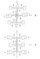
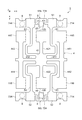
このようなジャイロ素子2は、いわゆるダブルT型をなす振動体4と、振動体4を支持する支持部としての第1支持部51および第2支持部52と、振動体4と第1支持部51とを連結する第1梁としての第1連結梁61および第2連結梁62と、振動体4と第2支持部52とを連結する第2梁としての第3連結梁63および第4連結梁64とを有している。
The
The
Such a
振動体4は、xy平面に拡がりを有し、z軸方向に厚みを有している。このような振動体4は、中央に位置する基部41と、基部41からy軸方向に沿って両側に延出している第1検出振動腕421、第2検出振動腕422と、基部41からx軸方向に沿って両側に延出している第1連結腕431、第2連結腕432と、第1連結腕431の先端部からy軸方向に沿って両側に延出している第1振動腕としての第1駆動振動腕441、および第2振動腕としての第3駆動振動腕442と、第2連結腕432の先端部からy軸方向に沿って両側に延出している第1振動腕としての第2駆動振動腕443、および第2振動腕としての第4駆動振動腕444とを有している。第1検出振動腕421、第2検出振動腕422および第1駆動振動腕441、第2駆動振動腕443、第3駆動振動腕442、第4駆動振動腕444の先端部には、それぞれ、基端側よりも幅の大きい略四角形の幅広部としての重量部(ハンマーヘッド)425,426,445,447,446,448が設けられている。このような重量部425,426,445,447,446,448を設けることでジャイロ素子2の角速度の検出感度が向上するとともに、第1、第2検出振動腕421,422、および第1、第2、第3、第4駆動振動腕441,443,442,444の長さを短くすることができる。
The vibrating
なお、第1駆動振動腕441、第3駆動振動腕442は、第1連結腕431の延在方向の途中から延出してもよく、同様に、第2駆動振動腕443、第4駆動振動腕444は、第2連結腕432の延在方向の途中から延出してもよい。
また、本形態では、基部41から延出している第1連結腕431、第2連結腕432から第1駆動振動腕441、第3駆動振動腕442、第2駆動振動腕443、および第4駆動振動腕444が延出している構成で説明したが、基部41と第1連結腕431と第2連結腕432とを含めて基部とすることも可能である。即ち、基部から第1駆動振動腕、第2駆動振動腕、第3駆動振動腕、および第4駆動振動腕が延出している構成も可能である。
The first
Further, in this embodiment, the first connecting
支持部は、第1支持部および第2支持部の少なくとも一方を含んでいる。本形態における支持部は、第1支持部51および第2支持部52を含んでいる。第1支持部51、および第2支持部52は、それぞれ、x軸方向に沿って延在しており、第1支持部51と第2支持部52との間に振動体4が位置している。言い換えれば、第1支持部51および第2支持部52は、振動体4を介してy軸方向に沿って対向するように配置されている。第1支持部51は、第1連結梁61、および第2連結梁62を介して基部41と連結されており、第2支持部52は、第3連結梁63、および第4連結梁64を介して基部41と連結されている。
The support part includes at least one of the first support part and the second support part. The support part in this embodiment includes a
第1支持部51には、第1連結梁61と接続されている部分(接続部)と、第2連結梁62と接続されている部分(接続部)との間に、弾性部としての連結部55が設けられている。連結部55は、細長い形状に第2方向(x軸方向)に沿って延在し、異なる方向に折り曲げられて形成されている。本形態の連結部55は、第1連結梁61と接続されている側の第1支持部51から第2連結梁62側に向かい第2方向に沿って延在し、その先で折り返されて第1連結梁61側に向かい第1方向に沿って延在し、その先で再び折り返されて第2連結梁62側に向かい第2方向に沿って延在し、第2連結梁62と接続されている側の第1支持部51に接続されている。
The
同様に第2支持部52には、第3連結梁63と接続されている部分と、第4連結梁64と接続されている部分との間に、弾性部としての連結部56が設けられている。連結部56は、細長い形状に第2方向(x軸方向)に沿って延在し、異なる方向に折り曲げられて形成されている。本形態の連結部56は、第3連結梁63との接続部側の第2支持部52から第4連結梁64側に向かい第2方向に沿って延在し、その先で折り返されて第3連結梁63側に向かい第1方向に沿って延在し、その先で再び折り返されて第4連結梁64側に向かい第2方向に沿って延在し、第4連結梁64と接続されている側の第2支持部52に接続されている。
Similarly, the
連結部55,56脇の第1支持部51および第2支持部52には、それぞれ検出接地端子724が設けられており、この検出接地端子724の部分が、導電性固定部材8を介して接続パッド10(図1参照)に電気的に接続されている。また、第1支持部51、第2支持部52に設けられている他の端子として検出信号端子714、駆動信号端子734および駆動接地端子744においても、検出接地端子724と同様に、導電性固定部材8を介して被固定部としての接続パッド10(図1参照)に電気的に接続される。
A
このような細長い形状の折り返し部を有する連結部55,56は、x軸方向およびy軸方向に撓み易い弾性を有している。この弾性により、第1駆動振動腕441、第2駆動振動腕443、第3駆動振動腕442、および第4駆動振動腕444の振動が基部41を伝わって漏れ出す振動モレ現象、あるいは後述する不要振動(y1モード振動)を吸収することができる。
なお、折り返し部は、第1方向に沿って1回以上折り返されていればよく、このような構成とすることで緩衝作用を有する弾性を生じる。
The connecting
In addition, the folding | returning part should just be folded back once or more along the 1st direction, and produces the elasticity which has a buffering effect by setting it as such a structure.
第1連結梁61は、第1検出振動腕421と第1駆動振動腕441との間を通って第1支持部51と基部41を連結し、第2連結梁62は、第1検出振動腕421と第2駆動振動腕443との間を通って第1支持部51と基部41を連結し、第3連結梁63は、第2検出振動腕422と第3駆動振動腕442との間を通って第2支持部52と基部41を連結し、第4連結梁64は、第2検出振動腕422と第4駆動振動腕444との間を通って第2支持部52と基部41を連結している。
The first connecting
このような各連結梁61,62,63,64は、それぞれ、x軸方向に沿って往復しながらy軸方向に沿って延びる蛇行部(S字形状部)を有しており、x軸方向およびy軸方向に弾性を有している。また、各連結梁61,62,63,64は、それぞれ、蛇行部を有する細長い形状を有しているので、あらゆる方向に弾性を有している。そのため、外部から衝撃が加えられても、各連結梁61,62,63,64で衝撃を吸収する作用を有するので、これに起因する検出ノイズを低減または抑制することができる。
Each of the connecting
上述のような構成のジャイロ素子2は、次のようにしてz軸まわりの角速度ωを検出する。ジャイロ素子2は、角速度ωが加わらない状態において、駆動信号電極(図示せず)および駆動接地電極(図示せず)の間に電界が生じると、図3(a)に示すように、各駆動振動腕441,443,442,444が矢印Aに示す方向に屈曲振動を行う。このとき、第1、第2駆動振動腕441,443と、第3、第4駆動振動腕442,444とは、中心点G(重心G)を通るyz平面に関して面対称の振動を行っているため、基部41と、第1、第2連結腕431,432と、第1、第2検出振動腕421,422とは、殆んど振動しない。
The
この駆動振動を行っている状態にて、ジャイロ素子2にz軸まわりに角速度ωが加わると、図3(b)に示すような振動が発生する。即ち、駆動振動腕441,443,442,444および連結腕431,432に矢印B方向のコリオリの力が働き、この矢印B方向の振動に呼応して、矢印C方向の検出振動が励起される。そして、この振動により発生した検出振動腕421,422の歪みを検出信号電極(図示せず)および検出接地電極(図示せず)が検出して角速度ωが求められる。
When an angular velocity ω is applied to the
(ジャイロ素子の不要振動モード)
ここで、ジャイロ素子2における不要振動について説明する。ジャイロ素子2においては、ジャイロ素子2が駆動している(動作している)際に、僅かではあるが励起される不要振動が発生する。この不要振動には種々の振動モードが存在するが、発明者らは、次に示す2つの振動モード(y1モードの振動、およびy2モードの振動)がジャイロ素子2の特性における温度ドリフトに大きな影響を持つことに着目した。
(Unnecessary vibration mode of gyro element)
Here, the unnecessary vibration in the
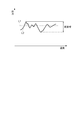
ここで図4、図5を用いてy1モード、およびy2モードの振動とそのジャイロ素子2の特性に対する影響について説明する。y1モード、およびy2モードの振動は、ジャイロ素子2が駆動している(動作している)際に、僅かではあるが励起される不要振動である。図4は、不要振動モードとしてのy1モード、およびy2モードの振動について説明する図であり、図4(a)はy1モードの振動、図4(b)はy2モードの振動を示す概略斜視図である。図5は、不要振動モードとしてのy1モード、およびy2モードの振動が、ジャイロ素子2の特性に与える影響についての説明図である。
Here, the vibrations in the y1 mode and the y2 mode and their influence on the characteristics of the
先ず、y1モードの振動について説明する。図4(a)に示すように、基部41の重心Gは、基部41からy軸方向に沿って延出されている第1、第2検出振動腕421,422とともに図示矢印P1の方向(−y軸方向)に移動する。このとき、基部41から第1、第2連結腕431,432を介して延出されている第1振動腕としての第1駆動振動腕441、第2振動腕としての第3駆動振動腕442、および第1振動腕としての第2駆動振動腕443、第2振動腕としての第4駆動振動腕444は、図示矢印P1の方向(−y軸方向)に移動する。即ち、y1モードは、基部41と、第1振動腕としての第1駆動振動腕441、第2振動腕としての第3駆動振動腕442、および第1振動腕としての第2駆動振動腕443、第2振動腕としての第4駆動振動腕444と、が同じ方向に動く(振動する)振動モードである。
First, the y1 mode vibration will be described. As shown in FIG. 4A, the center of gravity G of the
このようなy1モードの振動においては、基部41の重心Gと第1〜第4駆動振動腕441,443,442,444とが同じ方向に動くため、基部41の振動と第1〜第4駆動振動腕441,443,442,444の振動とが、閉じ込めきれずにジャイロ素子2の振動特性、特に温度に依存する特性変動である温度ドリフトに影響を与えてしまう。即ち、図5に示す曲線L2のように、温度が変化するにつれてジャイロ素子2の出力特性が変動する出力の変動幅が大きくなる、所謂温度ドリフトが大きくなってしまう。なお、温度ドリフトが生じなければ、図中L1のように殆んどふらつきのない特性が得られる。
In such y1 mode vibration, the center of gravity G of the
次に、y2モードの振動について説明する。図4(b)に示すように、基部41の重心Gは、基部41からy軸方向に沿って延出されている第1、第2検出振動腕421,422とともに図示矢印P1の方向(−y軸方向)に移動する。このとき、基部41から第1、第2連結腕431,432を介して延出されている第1振動腕としての第1駆動振動腕441、第2振動腕としての第3駆動振動腕442、および第1振動腕としての第2駆動振動腕443、第2振動腕としての第4駆動振動腕444は、図示矢印P2の方向(+y軸方向)に移動する。即ち、y2モードは、基部41の重心Gと、第1振動腕としての第1駆動振動腕441、第2振動腕としての第3駆動振動腕442、および第1振動腕としての第2駆動振動腕443、第2振動腕としての第4駆動振動腕444と、が互いに反対方向に動く(振動する)振動モードである。
Next, y2 mode vibration will be described. As shown in FIG. 4 (b), the center of gravity G of the
このようなy2モードの振動においては、基部41の重心Gと、第1〜第4駆動振動腕441,443,442,444とが、互いに反対方向に動くため、それぞれの動きによる振動が相殺され、それにより振動が閉じ込められることになる。したがって、このy2モードの振動は、ジャイロ素子2の振動特性、特に温度に依存する特性変動である温度ドリフトには、殆んど影響を与えることが無い。
In such y2 mode vibration, the center of gravity G of the
(パッケージ)
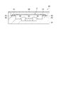
図1に戻りパッケージ9について説明する。パッケージ9は、ジャイロ素子2を収納するものである。なお、パッケージ9には、後述する電子デバイスのように、ジャイロ素子2の他に、ジャイロ素子2の駆動等を行うICチップ等が収納されていてもよい。このようなパッケージ9は、その平面視(xy平面視)にて、略矩形状をなしている。
(package)
Returning to FIG. 1, the
パッケージ9は、上面に開放する凹部を有するベース91と、凹部の開口を塞ぐようにベースに接合されているリッド(蓋体)92とを有している。また、ベース91は、板状の底板911と、底板911の上面周縁部に設けられている枠状の側壁912とを有している。このようなパッケージ9は、その内側に収納空間を有しており、この収納空間内に、ジャイロ素子2が気密的に収納、設置されている。
The
ジャイロ素子2は、第1支持部51、第2支持部52にて、半田、導電性接着剤(樹脂材料中に例えば銀の金属粒子などの導電性フィラーを分散させた接着剤)などの導電性固定部材8を介して底板911の上面に固定されている。第1支持部51、第2支持部52は、ジャイロ素子2のy軸方向の両端部に位置するため、このような部分を底板911に固定することにより、ジャイロ素子2の振動体4が両持ち支持され、ジャイロ素子2を底板911に対して安定的に固定することができる。そのため、ジャイロ素子2の不要な振動(検出振動以外の振動)が抑制され、ジャイロ素子2による角速度ωの検出精度が向上する。
The
また、導電性固定部材8は、第1支持部51、第2支持部52に設けられている2つの検出信号端子714、2つの検出接地端子724、駆動信号端子734および駆動接地端子744に対応(接触)して、かつ互いに離間して6つ設けられている。また、底板911の上面には、2つの検出信号端子714、2つの検出接地端子724、駆動信号端子734および駆動接地端子744に対応する6つの接続パッド10が設けられており、導電性固定部材8を介して、これら各接続パッド10とそれと対応するいずれかの端子とが電気的に接続されている。
The
上述の振動子1によれば、第1支持部51は、第1支持部51の第1連結梁61と第2連結梁62とのそれぞれの接続部の間に設けられている弾性部としての連結部55により、撓み易くなる。また、第2支持部52は、第2支持部52の第3連結梁63と第4連結梁64とのそれぞれの接続部の間に設けられている弾性部としての連結部56により、撓み易くなる。このように、第1支持部51および第2支持部52が撓むことにより、第1駆動振動腕441、第2駆動振動腕443、第3駆動振動腕442、および第4駆動振動腕444の振動が基部41を伝わって漏れ出す振動モレ現象、あるいは不要振動(y1モード振動)を吸収することができる。これにより、ジャイロ素子2の振動特性の劣化、特に温度ドリフトを低減させることが可能となり、このジャイロ素子2を用いた振動子1においても同様に、振動特性の劣化、特に温度ドリフトを低減させることが可能となる。
According to the vibrator 1 described above, the
(ジャイロ素子の第2実施形態)
ジャイロ素子の第2実施形態について図6を用いて説明する。図6は、第2実施形態のジャイロ素子の概略を示す平面図である。なお、本第2実施形態の説明では、上述の第1実施形態と同じ構成については同符号を付けてその説明を省略することがある。
(Second Embodiment of Gyro Element)
A second embodiment of the gyro element will be described with reference to FIG. FIG. 6 is a plan view schematically showing the gyro element of the second embodiment. In the description of the second embodiment, the same components as those in the first embodiment described above may be denoted by the same reference numerals and the description thereof may be omitted.
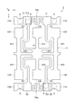
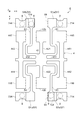
図6に示すように、第2実施形態のジャイロ素子3は、いわゆるダブルT型をなす振動体4と、振動体4を支持する支持部と、振動体4と支持部とを連結する梁とを有している。ここで、第2実施形態のジャイロ素子3と前述の第1実施形態のジャイロ素子2との相違は、第1支持部51と第2支持部52に設けられている連結部55a,56aの構成である。
As shown in FIG. 6, the
本形態における支持部は、第1支持部51および第2支持部52を含んでいる。第1支持部51、および第2支持部52は、それぞれ、x軸方向に沿って延在しており、第1支持部51と第2支持部52との間に振動体4が位置している。言い換えれば、第1支持部51および第2支持部52は、振動体4を介してy軸方向に沿って対向するように配置されている。第1支持部51は、第1連結梁61、および第2連結梁62を介して基部41と連結されており、第2支持部52は、第3連結梁63、および第4連結梁64を介して基部41と連結されている。
The support part in this embodiment includes a
第1支持部51には、第1連結梁61と接続されている部分(接続部)と、第2連結梁62と接続されている部分(接続部)との間に、弾性部としての連結部55aが設けられている。連結部55aは、細長い形状に延在し、異なる方向に曲げられて形成されている。
本形態の連結部55aは、第1連結梁61との接続部側の第1支持部51から第2連結梁62側(−x軸方向)に向かった後、−y軸方向に延在し、その先で折り返されて+y軸方向に向かい、その先で折り返されて再び−y軸方向に向かい、その先で折り返されて再び+y軸方向に向かった後、第2連結梁62側(−x軸方向)に向い第2連結梁62側の第1支持部51に接続されている。
The
The connecting
同様に第2支持部52には、第3連結梁63と接続されている部分(接続部)と、第4連結梁64と接続されている部分(接続部)との間に、弾性部としての連結部56aが設けられている。連結部56aは、細長い形状に延在し、異なる方向に曲げられて形成されている。
本形態の連結部56aは、第3連結梁63との接続部側の第2支持部52から第4連結梁64側(−x軸方向)に向かった後、+y軸方向に延在し、その先で折り返されて−y軸方向に向かい、その先で折り返されて再び+y軸方向に向かい、その先で折り返されて再び−y軸方向に向かった後、第4連結梁64側(−x軸方向)に向い第4連結梁64側の第2支持部52に接続されている。
Similarly, the
The connecting
連結部55a,56a脇の第1支持部51および第2支持部52には、それぞれ検出接地端子724が設けられており、この検出接地端子724の部分が、導電性固定部材8を介して接続パッド10(図1参照)に電気的に接続されている。また、第1支持部51、第2支持部52に設けられている他の端子として検出信号端子714、駆動信号端子734および駆動接地端子744においても、検出接地端子724と同様に、導電性固定部材8を介して被固定部としての接続パッド10(図1参照)に電気的に接続される。
Each of the
このような細長い形状の折り返し部を有する連結部55a,56aは、x軸方向およびy軸方向に撓み易い弾性を有している。この弾性により、前述の第1実施形態のジャイロ素子2と同様に、第1駆動振動腕441、第2駆動振動腕443、第3駆動振動腕442、および第4駆動振動腕444の振動が基部41を伝わって漏れ出す振動モレ現象、あるいは不要振動(y1モード振動)を吸収することができる。
なお、折り返し部は、1回以上折り返されていればよく、このような構成とすることで緩衝作用を有する弾性を生じる。また、折り返し部は、矩形形状に限らず、例えば湾曲形状であってもよい。
The connecting
In addition, the folding | returning part should just be folded back once or more, and the elasticity which has a buffering effect is produced by setting it as such a structure. Further, the folded portion is not limited to a rectangular shape, and may be, for example, a curved shape.
(ジャイロ素子の第3実施形態)
ジャイロ素子の第3実施形態について図7を用いて説明する。図7は、第3実施形態のジャイロ素子の概略を示す平面図である。なお、本第3実施形態の説明では、上述の第1実施形態と同じ構成については同符号を付けてその説明を省略することがある。
(Third embodiment of gyro element)
A third embodiment of the gyro element will be described with reference to FIG. FIG. 7 is a plan view schematically showing the gyro element of the third embodiment. In the description of the third embodiment, the same components as those in the first embodiment described above may be denoted by the same reference numerals and the description thereof may be omitted.
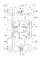
図7に示すように、第3実施形態のジャイロ素子5は、いわゆるダブルT型をなす振動体4と、振動体4を支持する支持部と、振動体4と支持部とを連結する梁とを有している。ここで、第3実施形態のジャイロ素子5と前述の第1実施形態のジャイロ素子2との相違は、第1支持部51と第2支持部52に設けられている連結部55b,56bの構成であり、詳しくは連結部55b,56bのそれぞれに接続されたアンカー部57,58が備えられていることである。
As shown in FIG. 7, the
本形態における支持部は、前述の第1実施形態と同様に、第1支持部51および第2支持部52を含んでいる。第1支持部51、および第2支持部52と、それぞれに接続されている第1連結梁61、第2連結梁62、第3連結梁63、第4連結梁64、および基部41の構成は、前述の第1実施形態と同様であるので説明を省略する。
The support part in this form contains the
第1支持部51には、第1連結梁61と接続されている部分(接続部)と、第2連結梁62と接続されている部分(接続部)との間に、弾性部としての連結部55bが設けられている。連結部55bには、細長い形状に延在し異なる方向に折り曲げられた部分と、細長い形状が延在している部分から延びるアンカー部57が設けられている。
本形態の連結部55bは、第1連結梁61と接続されている側の第1支持部51から第2連結梁62側(−x軸方向)に向かった後、−y軸方向に延在し、その先で折り曲って−x軸方向に向かう部分に、アンカー部57が設けられている。さらに、アンカー部57から細長い形状で延在された先で折り曲って+y軸方向に向かい、再び折り曲って−x軸方向に向い第2連結梁62側の第1支持部51に接続されている。
アンカー部57は、連結部55bから基部41側(+y軸方向)に延在し、+y軸方向の端が重量部425と対向するように設けられている。
The
The connecting
The
同様に第2支持部52には、第3連結梁63と接続されている部分(接続部)と、第4連結梁64と接続されている部分(接続部)との間に、弾性部としての連結部56bが設けられている。連結部56bには、細長い形状に延在し異なる方向に折り曲げられた部分と、細長い形状が延在している部分から延びるアンカー部58が設けられている。
本形態の連結部56bは、第3連結梁63と接続されている側の第2支持部52から第4連結梁64側(−x軸方向)に向かった後、+y軸方向に延在し、その先で折り曲って−x軸方向に向かう部分に、アンカー部58が設けられている。さらに、アンカー部58から細長い形状で延在された先で折り曲って−y軸方向に向かい、再び折り曲って−x軸方向に向い第4連結梁64側の第2支持部52に接続されている。
アンカー部58は、連結部56bから基部41側(−y軸方向)に延在し、−y軸方向の端が重量部426と対向するように設けられている。
Similarly, the
The connecting
The
このように設けられたアンカー部57,58は、ジャイロ素子5が固定される被固定部に接続される。アンカー部57,58には、それぞれ検出接地端子724が設けられており、この検出接地端子724の部分が、導電性固定部材8を介して接続パッド10(図1参照)に電気的に接続されている。また、第1支持部51、第2支持部52に設けられている他の端子である検出信号端子714、駆動信号端子734および駆動接地端子744においても、検出接地端子724と同様に、導電性固定部材8を介して被固定部としての接続パッド10(図1参照)に電気的に接続されている。
The
このようなアンカー部57,58が被固定部に接続されても、アンカー部57,58の両側に設けられている連結部55b,56bは、細長く折り曲げられた形状をなしているため、撓み易く、この撓みにより振動モレ現象、あるいは不要振動(y1モード振動)を吸収することができる。これにより、振動特性の劣化を防止し、安定した出力特性を有する振動素子としてのジャイロ素子5を得ることができる。
Even if the
(ジャイロ素子の第4実施形態)
ジャイロ素子の第4実施形態について図8を用いて説明する。図8は、第4実施形態のジャイロ素子の概略を示す平面図である。なお、本第4実施形態の説明では、上述の第1実施形態と同じ構成については同符号を付けてその説明を省略することがある。
(Fourth embodiment of gyro element)
A fourth embodiment of the gyro element will be described with reference to FIG. FIG. 8 is a plan view schematically showing the gyro element of the fourth embodiment. In the description of the fourth embodiment, the same components as those in the first embodiment described above may be denoted by the same reference numerals and description thereof may be omitted.
図8に示すように、第4実施形態のジャイロ素子6は、いわゆるダブルT型をなす振動体4と、振動体4を支持する支持部と、振動体4と支持部とを連結する梁とを有している。ここで、第4実施形態のジャイロ素子6と前述の第1実施形態のジャイロ素子2との相違は、第1支持部51と第2支持部52とが二つに分割されていることである。
As shown in FIG. 8, the
本形態における支持部は、第1支持部51および第2支持部52の少なくとも一方を含んでいる。本形態における支持部は、第1支持部51および第2支持部52を含んでいる。また、第1支持部51は、第3支持部51aと第4支持部51bとを含み、第2支持部52は、第5支持部52aと第6支持部52bとを含んでいる。そして、第3支持部51aには第1連結梁61が接続され、第4支持部51bには第2連結梁62が接続されている。また、第5支持部52aには第3連結梁63が接続され、第6支持部52bには第4連結梁64が接続されている。
The support part in this embodiment includes at least one of the
第1支持部51は、空間59を挟んで二つに分割され、第3支持部51aと第4支持部51bが設けられている。換言すると、第3支持部51aと第4支持部51bとの間に空間59が配置されている。また、第2支持部52は、空間60を挟んで二つに分割され、第5支持部52aと第6支持部52bが設けられている。換言すると、第5支持部52aと第6支持部52bとの間に空間60が配置されている。
The
第4支持部51bには、検出接地端子724と駆動接地端子744が設けられ、第6支持部52bには、駆動信号端子734が設けられている。また、第3支持部51aには、検出信号端子714が設けられ、第5支持部52aには、検出信号端子714と検出接地端子724とが設けられている。ジャイロ素子6は、このようなそれぞれの端子の位置において、導電性固定部材8を介して接続パッド10(図1参照)に電気的に接続される。
The
このような構成のジャイロ素子6によれば、それぞれの梁がそれぞれの支持部に接続されていることから、それぞれの梁に伝わる振動モレ現象、あるいは不要振動などが互いに干渉することが無くなり、干渉による温度ドリフトなどの振動特性の劣化を減少させることが可能となる。
According to the
(ジャイロ素子の固定位置の変形例)
ジャイロ素子の固定位置の変形例について図9を用いて説明する。図9は、ジャイロ素子における固定位置の変形例を示す平面図である。なお、ここでの説明では、上述の第1実施形態と同じ構成については同符号を付けてその説明を省略することがある。
(Modification of fixed position of gyro element)
A modification of the fixed position of the gyro element will be described with reference to FIG. FIG. 9 is a plan view showing a modification of the fixed position in the gyro element. In the description here, the same components as those in the first embodiment described above may be denoted by the same reference numerals and description thereof may be omitted.
図9に示すジャイロ素子2の基本的な構成は、前述した第1実施形態と同様である。本変形例では、ジャイロ素子2の固定位置が第1実施形態と異なっている。本変形例におけるジャイロ素子2の固定位置は、細長い形状をなして、折り返された部分を有する連結部55,56にも設けられる。
The basic configuration of the
連結部55,56の一部には、それぞれ検出接地端子724が設けられており、この検出接地端子724の部分が、導電性固定部材8を介して接続パッド10(図1参照)に電気的に接続される。また、第1支持部51、第2支持部52に設けられている他の端子である検出信号端子714、駆動信号端子734および駆動接地端子744においても、検出接地端子724と同様に、導電性固定部材8を介して被固定部としての接続パッド10(図1参照)に電気的に接続される。
A
このように、連結部55,56の一部に設けられた検出接地端子724の部分が、導電性固定部材8を介して接続パッド10(図1参照)に電気的に接続されても、被固定部の両側に設けられている細長形状の連結部55,56の撓みにより、第1支持部51、第2支持部52が固定されることによって特性に影響を生じ易くなる、振動モレ現象、あるいは不要振動(y1モード振動)を吸収することができる。
As described above, even if the portion of the
なお、本発明に係る振動素子は、基板上に形成された圧電薄膜を振動源とする圧電薄膜駆動型の振動素子、MEMS(Micro Electro Mechanical System)型の振動素子、静電駆動型の振動素子などにも適用することが可能である。 Note that the vibration element according to the present invention includes a piezoelectric thin film driving type vibration element using a piezoelectric thin film formed on a substrate as a vibration source, a MEMS (Micro Electro Mechanical System) type vibration element, and an electrostatic drive type vibration element. It is also possible to apply it.
[電子デバイス]
次に、上述のジャイロ素子2,3,5,6を用いた電子デバイスの一例としてのジャイロセンサーについて、図10を用いて説明する。図10はジャイロセンサーの概略を示す正断面図である。なお、ここでの説明では、上述の実施形態の内、第1実施形態のジャイロ素子2を用いた例で説明する。
[Electronic device]
Next, a gyro sensor as an example of an electronic device using the above-described
ジャイロセンサー80は、振動素子としてのジャイロ素子2、回路素子としてのIC84、パッケージとしての収容器81、蓋体86を備えている。セラミックなどで形成された収容器81の底面にはIC84が配置され、Auなどのワイヤー85で収容器81に形成された配線(図示せず)と電気的接続がなされている。IC84にはジャイロ素子2を駆動振動させるための駆動回路と、角速度が加わったときにジャイロ素子2に生ずる検出信号を検出する検出回路とを含んでいる。
The
ジャイロ素子2は、収容器81に形成された支持台82に、ジャイロ素子2の第1支持部51、第2支持部52の一部が導電性接着剤などの固定部材83を介して接着支持されている。また、支持台82表面には配線(図示せず)が形成され、ジャイロ素子2の電極と配線間の導通が固定部材83を介してなされている。この固定部材83は、弾性のある材料であることが望ましい。弾性を有する固定部材83としてはシリコーンを基材とする導電性接着剤などが知られている。そして、収容器81内を真空雰囲気に保持し、収容器81の上部の開口が蓋体86にて封止されている。
The
ジャイロセンサー80によれば、用いているジャイロ素子2において、振動モレ現象、不要モード振動が固定位置まで伝播することが抑制されているため、振動モレ現象による温度ドリフトを低減させることが可能となり、前述の不要振動による温度ドリフトの低減と合わせて、温度ドリフトを低減させ、安定した角速度の検出が可能となる。
According to the
上述の電子デバイスの説明では、振動素子として所謂ダブルT型のジャイロ素子2を用いたジャイロセンサー80を例に説明したが、電子デバイスとしてはこれに限らない。他の電子デバイスとしては、例えば素子としてH型、あるいは音叉型のジャイロ素子を用いたジャイロセンサー、水晶振動素子(振動素子)を用いたタイミングデバイス(水晶振動子、水晶発振器など)、感圧素子を用いた圧力センサーなどであってもよい。
In the above description of the electronic device, the
[電子機器]
次いで、本発明の一実施形態に係る振動素子としてのジャイロ素子2,3,5,6を用いた振動子1あるいは電子デバイスとしてのジャイロセンサー80を適用した電子機器について、図11〜図13に基づき、詳細に説明する。なお、説明では、振動素子としてのジャイロ素子2を用いた振動子1を適用した例を示している。
[Electronics]
Next, electronic devices to which the vibrator 1 using the
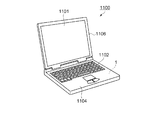
図11は、本発明の一実施形態に係る振動子1を備える電子機器としてのモバイル型(又はノート型)のパーソナルコンピューターの構成の概略を示す斜視図である。この図において、パーソナルコンピューター1100は、キーボード1102を備えた本体部1104と、表示部1101を備えた表示ユニット1106とにより構成され、表示ユニット1106は、本体部1104に対しヒンジ構造部を介して回動可能に支持されている。このようなパーソナルコンピューター1100には、角速度を検出する機能を備えたジャイロ素子2を用いた振動子1が内蔵されている。
FIG. 11 is a perspective view schematically illustrating a configuration of a mobile (or notebook) personal computer as an electronic apparatus including the vibrator 1 according to the embodiment of the invention. In this figure, a
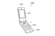
図12は、本発明の一実施形態に係る振動子1を備える電子機器としての携帯電話機(PHSも含む)の構成の概略を示す斜視図である。この図において、携帯電話機1200は、複数の操作ボタン1202、受話口1204および送話口1206を備え、操作ボタン1202と受話口1204との間には、表示部1201が配置されている。このような携帯電話機1200には、角速度センサー等として機能するジャイロ素子2を用いた振動子1が内蔵されている。
FIG. 12 is a perspective view schematically illustrating a configuration of a mobile phone (including PHS) as an electronic apparatus including the vibrator 1 according to the embodiment of the invention. In this figure, a
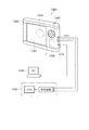
図13は、本発明の一実施形態に係る振動子1を備える電子機器としてのデジタルスチールカメラの構成の概略を示す斜視図である。なお、この図には、外部機器との接続についても簡易的に示されている。ここで、通常のカメラは、被写体の光像により銀塩写真フィルムを感光するのに対し、デジタルスチールカメラ1300は、被写体の光像をCCD(Charge Coupled Device)等の撮像素子により光電変換して撮像信号(画像信号)を生成する。
FIG. 13 is a perspective view schematically illustrating a configuration of a digital still camera as an electronic apparatus including the vibrator 1 according to the embodiment of the invention. In this figure, connection with an external device is also simply shown. Here, an ordinary camera sensitizes a silver halide photographic film with a light image of a subject, whereas a
デジタルスチールカメラ1300におけるケース(ボディー)1302の背面には、表示部1301が設けられ、CCDによる撮像信号に基づいて表示を行う構成になっており、表示部1301は、被写体を電子画像として表示するファインダーとして機能する。また、ケース1302の正面側(図中裏面側)には、光学レンズ(撮像光学系)やCCD等を含む受光ユニット1304が設けられている。
A
撮影者が表示部1301に表示された被写体像を確認し、シャッターボタン1306を押下すると、その時点におけるCCDの撮像信号が、メモリー1308に転送・格納される。また、このデジタルスチールカメラ1300においては、ケース1302の側面に、ビデオ信号出力端子1312と、データ通信用の入出力端子1314とが設けられている。そして、図示されるように、ビデオ信号出力端子1312にはテレビモニター1430が、データ通信用の入出力端子1314にはパーソナルコンピューター1440が、それぞれ必要に応じて接続される。さらに、所定の操作により、メモリー1308に格納された撮像信号が、テレビモニター1430や、パーソナルコンピューター1440に出力される構成になっている。このようなデジタルスチールカメラ1300には、角速度センサー等として機能するジャイロ素子2を用いた振動子1が内蔵されている。
When the photographer confirms the subject image displayed on the
なお、本発明の一実施形態に係る振動子1は、図11のパーソナルコンピューター(モバイル型パーソナルコンピューター)、図12の携帯電話機、図13のデジタルスチールカメラの他にも、例えば、インクジェット式吐出装置(例えばインクジェットプリンター)、ラップトップ型パーソナルコンピューター、テレビ、ビデオカメラ、ビデオテープレコーダー、カーナビゲーション装置、ページャー、電子手帳(通信機能付も含む)、電子辞書、電卓、電子ゲーム機器、ワードプロセッサー、ワークステーション、テレビ電話、防犯用テレビモニター、電子双眼鏡、POS端末、医療機器(例えば電子体温計、血圧計、血糖計、心電図計測装置、超音波診断装置、電子内視鏡)、魚群探知機、各種測定機器、計器類(例えば、車両、航空機、船舶の計器類)、フライトシミュレーター等の電子機器に適用することができる。 In addition to the personal computer (mobile personal computer) in FIG. 11, the mobile phone in FIG. 12, and the digital still camera in FIG. (For example, inkjet printers), laptop personal computers, televisions, video cameras, video tape recorders, car navigation devices, pagers, electronic notebooks (including those with communication functions), electronic dictionaries, calculators, electronic game devices, word processors, workstations , Video phone, crime prevention TV monitor, electronic binoculars, POS terminal, medical equipment (eg, electronic thermometer, blood pressure monitor, blood glucose meter, electrocardiogram measuring device, ultrasonic diagnostic device, electronic endoscope), fish detector, various measuring devices , Instruments (eg, vehicles, aviation , Gauges of a ship), can be applied to electronic equipment such as a flight simulator.
[移動体]
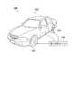
図14は移動体の一例としての自動車を概略的に示す斜視図である。自動車506には本発明に係るジャイロ素子2を用いた振動子1が搭載されている。例えば、同図に示すように、移動体としての自動車506には、ジャイロ素子2を用いた振動子1を内蔵してタイヤ509などを制御する電子制御ユニット508が車体507に搭載されている。また、振動子1は、他にもキーレスエントリー、イモビライザー、カーナビゲーションシステム、カーエアコン、アンチロックブレーキシステム(ABS)、エアバック、タイヤ・プレッシャー・モニタリング・システム(TPMS:Tire Pressure Monitoring System)、エンジンコントロール、ハイブリッド自動車や電気自動車の電池モニター、車体姿勢制御システム、等の電子制御ユニット(ECU:electronic control unit)に広く適用できる。
[Moving object]
FIG. 14 is a perspective view schematically showing an automobile as an example of a moving body. The
1…振動子、2,3,5,6…振動素子としてのジャイロ素子、4…振動体、8…導電性固定部材(導電性接着剤)、9…パッケージ、10…接続パッド、41…基部、51…支持部としての第1支持部、52…支持部としての第2支持部、55,56…連結部、57,58…アンカー部、59,60…空間、61…第1梁としての第1連結梁、62…第1梁としての第2連結梁、63…第2梁としての第3連結梁、64…第2梁としての第4連結梁、80…電子デバイスとしてのジャイロセンサー、91…ベース、92…リッド、421…第1検出振動腕、422…第2検出振動腕、425,426,445,446,447,448…重量部(ハンマーヘッド)、431…第1連結腕、432…第2連結腕、441…第1振動腕としての第1駆動振動腕、442…第2振動腕としての第3駆動振動腕、443…第1振動腕としての第2駆動振動腕、444…第2振動腕としての第4駆動振動腕、506…移動体としての自動車、714…検出信号端子、724…検出接地端子、734…駆動信号端子、744…駆動接地端子、911…底板、912…側壁、1100…電子機器としてのモバイル型のパーソナルコンピューター、1200…電子機器としての携帯電話機、1300…電子機器としてのデジタルスチールカメラ。 DESCRIPTION OF SYMBOLS 1 ... Vibrator, 2, 3, 5, 6 ... Gyro element as vibration element, 4 ... Vibrating body, 8 ... Conductive fixing member (conductive adhesive), 9 ... Package, 10 ... Connection pad, 41 ... Base , 51 ... 1st support part as a support part, 52 ... 2nd support part as a support part, 55, 56 ... Connecting part, 57, 58 ... Anchor part, 59, 60 ... Space, 61 ... As 1st beam First connecting beam, 62 ... Second connecting beam as the first beam, 63 ... Third connecting beam as the second beam, 64 ... Fourth connecting beam as the second beam, 80 ... Gyro sensor as an electronic device, 91 ... Base, 92 ... Lid, 421 ... First detection vibration arm, 422 ... Second detection vibration arm, 425, 426, 445, 446, 447, 448 ... Weight part (hammer head), 431 ... First connection arm, 432 ... second connecting arm, 441 ... as first vibrating arm 1 drive vibration arm, 442... 3rd drive vibration arm as the second vibration arm, 443... 2nd drive vibration arm as the first vibration arm, 444... 4th drive vibration arm as the second vibration arm, 506. Automobile as a body, 714 ... detection signal terminal, 724 ... detection ground terminal, 734 ... drive signal terminal, 744 ... drive ground terminal, 911 ... bottom plate, 912 ... side wall, 1100 ... mobile personal computer as electronic equipment, 1200 ... mobile phone as electronic equipment, 1300 ... digital still camera as electronic equipment.
Claims (12)
前記基部から第1方向に延出されている第1振動腕と、
前記基部から前記第1方向に延出されている第2振動腕と、
前記基部から前記第1方向に延出されている第1連結梁および第2連結梁を含む第1梁と、
前記第1方向と交差する第2方向に延出され、前記第1連結梁および前記第2連結梁が接続されている支持部と、を備え、
前記支持部は、前記第1連結梁と前記支持部との接続部と、前記第2連結梁と前記支持部との接続部と、の間に弾性部が設けられていることを特徴とする振動素子。 The base,
A first vibrating arm extending in a first direction from the base;
A second vibrating arm extending in the first direction from the base;
A first beam including a first connecting beam and a second connecting beam extending from the base in the first direction;
Extending in a second direction intersecting the first direction, and a support part to which the first and second connection beams are connected, and
The support part is characterized in that an elastic part is provided between a connection part between the first connection beam and the support part and a connection part between the second connection beam and the support part. Vibration element.
前記第1振動腕は、前記基部から前記第1方向の両側へ延出している第1検出振動腕および第2検出振動腕を備え、
前記第2振動腕は、前記第1検出振動腕および前記第2検出振動腕の前記第2方向の両側にあって、前記基部から前記第1方向の両側へ前記第1検出振動腕および前記第2検出振動腕の延出方向に沿って延出されている第1駆動振動腕および第2駆動振動腕と、第3駆動振動腕および第4駆動振動腕と、を備え、
前記支持部は、前記基部の両側に、第1支持部、および第2支持部を備え、
前記第1梁は、前記第1検出振動腕と前記第1駆動振動腕との間を通って前記第1支持部と連結されている前記第1連結梁と、前記第1検出振動腕と前記第2駆動振動腕との間を通って前記第1支持部と連結されている前記第2連結梁と、を備え、
前記第2梁は、前記第2検出振動腕と前記第3駆動振動腕との間を通って前記第2支持部と連結されている前記第3連結梁と、前記第2検出振動腕と前記第4駆動振動腕との間を通って前記第2支持部と連結されている前記第4連結梁と、を備えていることを特徴とする請求項1ないし請求項4のいずれか一項に記載の振動素子。 A second beam including a third connecting beam and a fourth connecting beam extending from the base in a direction opposite to the extending direction of the first beam;
The first vibrating arm includes a first detection vibrating arm and a second detection vibrating arm extending from the base to both sides in the first direction,
The second vibrating arm is on both sides of the first detection vibrating arm and the second detection vibrating arm in the second direction, and extends from the base to both sides in the first direction. A first drive vibration arm and a second drive vibration arm that extend along the extending direction of the two detection vibration arms; a third drive vibration arm and a fourth drive vibration arm;
The support part includes a first support part and a second support part on both sides of the base part,
The first beam passes between the first detection vibrating arm and the first drive vibrating arm and is connected to the first support portion, the first detection vibrating arm, and the first beam. The second connecting beam that is connected to the first support portion through the second drive vibrating arm, and
The second beam passes between the second detection vibrating arm and the third drive vibrating arm and is connected to the second support portion, the second detection vibrating arm, and the second detection vibrating arm. 5. The fourth connecting beam connected to the second support portion through the fourth drive vibrating arm, and the fourth connecting beam according to claim 1. The vibration element described.
前記基部から第1方向に延出されている第1振動腕と、
前記基部から前記第1方向に延出されている第2振動腕と、
前記基部から前記第1方向に延出されている第1連結梁および第2連結梁と、
前記第1連結梁が接続されている第3支持部と、
前記第2連結梁が接続されている第4支持部と、が備えられていることを特徴とする振動素子。 The base,
A first vibrating arm extending in a first direction from the base;
A second vibrating arm extending in the first direction from the base;
A first connecting beam and a second connecting beam extending in the first direction from the base;
A third support to which the first connecting beam is connected;
And a fourth support portion to which the second connecting beam is connected.
前記振動素子が収納されているパッケージと、を備えていることを特徴とする振動子。 The vibration element according to any one of claims 1 to 8,
And a package in which the vibration element is housed.
少なくとも前記振動素子を駆動させる機能を有している回路素子と、を備えていることを特徴とする電子デバイス。 The vibration element according to any one of claims 1 to 8,
An electronic device comprising: at least a circuit element having a function of driving the vibration element.
Priority Applications (1)
| Application Number | Priority Date | Filing Date | Title |
|---|---|---|---|
| JP2013257785A JP2015114253A (en) | 2013-12-13 | 2013-12-13 | Vibration element, vibrator, electronic device, electronic device, and moving object |
Applications Claiming Priority (1)
| Application Number | Priority Date | Filing Date | Title |
|---|---|---|---|
| JP2013257785A JP2015114253A (en) | 2013-12-13 | 2013-12-13 | Vibration element, vibrator, electronic device, electronic device, and moving object |
Publications (1)
| Publication Number | Publication Date |
|---|---|
| JP2015114253A true JP2015114253A (en) | 2015-06-22 |
Family
ID=53528171
Family Applications (1)
| Application Number | Title | Priority Date | Filing Date |
|---|---|---|---|
| JP2013257785A Pending JP2015114253A (en) | 2013-12-13 | 2013-12-13 | Vibration element, vibrator, electronic device, electronic device, and moving object |
Country Status (1)
| Country | Link |
|---|---|
| JP (1) | JP2015114253A (en) |
-
2013
- 2013-12-13 JP JP2013257785A patent/JP2015114253A/en active Pending
Similar Documents
| Publication | Publication Date | Title |
|---|---|---|
| JP6074967B2 (en) | Vibrating piece, vibrator, electronic device, electronic device, and moving object | |
| CN103575261B (en) | Vibrating reed and its preparation method, oscillator, electronic installation, electronic equipment and moving body | |
| US10794778B2 (en) | Physical quantity detecting device, electronic apparatus, and moving object | |
| CN105758395B (en) | Physical Quantity Sensors, Electronic Devices, and Moving Objects | |
| JP6435596B2 (en) | Vibration element, vibration device, electronic device, and moving object | |
| JP6582501B2 (en) | Vibration element, vibrator, electronic device and moving body | |
| JP2015184157A (en) | Physical quantity detection circuit, physical quantity detection device, electronic apparatus, and mobile entity | |
| JP2015087262A (en) | Vibration element, vibrator, electronic apparatus and movable body | |
| JP6432652B2 (en) | Manufacturing method of vibrating piece | |
| JP2014178165A (en) | Vibration element, transducer, electronic device, electronic apparatus, and mobile body | |
| CN104579225B (en) | Vibrating elements, oscillator, oscillator, electronic equipment and moving body | |
| JP2014092500A (en) | Vibration piece, vibrator, electronic device, electronic apparatus, and mobile body | |
| JP2016044977A (en) | Sensor element, sensor device, electronic device and mobile object | |
| JP2015114253A (en) | Vibration element, vibrator, electronic device, electronic device, and moving object | |
| JP2016061710A (en) | Vibration element, gyro element, electronic device, electronic equipment, and mobile body | |
| JP2016186479A (en) | Physical quantity detection vibration element, physical quantity detection vibrator, electronic apparatus and mobile body | |
| JP6569257B2 (en) | Vibration element, electronic device, electronic device, and moving object | |
| JP2014025742A (en) | Vibration piece, gyro sensor, electronic apparatus and movable body | |
| JP2015169648A (en) | Functional element, electronic device, physical quantity detection apparatus, electronic apparatus, and mobile body | |
| JP6264842B2 (en) | Vibration element, vibrator, oscillator, electronic device, and moving object | |
| JP2016038306A (en) | Sensor element, sensor device, electronic device and mobile object | |
| JP2016085183A (en) | Sensor element, physical quantity sensor, electronic apparatus and movable body | |
| JP2013250187A (en) | Electronic device, electronic apparatus, and movable body | |
| JP2015087187A (en) | Vibrating piece, angular velocity sensor, electronic device and moving object | |
| JP2016048191A (en) | Sensor element, sensor device, electronic device and mobile object |
Legal Events
| Date | Code | Title | Description |
|---|---|---|---|
| RD04 | Notification of resignation of power of attorney |
Free format text: JAPANESE INTERMEDIATE CODE: A7424 Effective date: 20160614 |
|
| RD03 | Notification of appointment of power of attorney |
Free format text: JAPANESE INTERMEDIATE CODE: A7423 Effective date: 20160624 |