JP2015114017A - Heating cooker and high frequency heating cooker - Google Patents
Heating cooker and high frequency heating cooker Download PDFInfo
- Publication number
- JP2015114017A JP2015114017A JP2013255249A JP2013255249A JP2015114017A JP 2015114017 A JP2015114017 A JP 2015114017A JP 2013255249 A JP2013255249 A JP 2013255249A JP 2013255249 A JP2013255249 A JP 2013255249A JP 2015114017 A JP2015114017 A JP 2015114017A
- Authority
- JP
- Japan
- Prior art keywords
- frequency
- cooking device
- heating
- heating element
- lid
- Prior art date
- Legal status (The legal status is an assumption and is not a legal conclusion. Google has not performed a legal analysis and makes no representation as to the accuracy of the status listed.)
- Pending
Links
Images
Landscapes
- Electric Ovens (AREA)
Abstract
Description
本発明は、高周波で発熱して内部の被加熱物を加熱する加熱調理器具、及びこの加熱調理器具を備えた高周波加熱調理器に関するものである。 The present invention relates to a cooking device that generates heat at a high frequency to heat an object to be heated, and a high-frequency heating cooker that includes the cooking device.
従来、電子レンジ用の加熱調理器具は、被加熱物を載せる皿と、皿全体を覆う蓋体とで構成され、皿の上に被加熱物を載せて蓋体で覆い、高周波加熱することで被加熱物を加熱調理している。
また、従来の加熱調理器具として、高周波を吸収して発熱する発熱体を皿に設けたもの、あるいは皿と蓋体の双方に発熱体を設けた加熱調理器具がある。これらのものにおいては、高周波加熱によって発熱体の温度が例えば250℃位まで上昇するため、被加熱物に焦げ目を付けることができる(例えば、特許文献1参照)。
Conventionally, a cooking device for a microwave oven is composed of a dish on which an object to be heated is placed and a lid that covers the entire dish, and the object to be heated is placed on the dish, covered with a lid, and heated by high frequency. The object to be heated is cooked.
Further, as a conventional cooking device, there are a cooking device in which a heating element that absorbs high frequency to generate heat is provided on a plate, or a cooking device in which a heating element is provided on both a plate and a lid. In these things, since the temperature of a heat generating body raises to about 250 degreeC by high frequency heating, for example, a to-be-heated object can be burnt (for example, refer patent document 1).
しかしながら、前述した技術では、高周波加熱により被加熱物から出た脂等が皿上で過熱されてしまうことがあった。また、蓋体を有する加熱調理器具においては、被加熱物から出た蒸気が蓋体内で結露し、その結露水が再び被加熱物に付着してしまい、被加熱物がべちゃっとした仕上がりになってしまうという課題があった。 However, in the above-described technique, fat or the like that has come out of the object to be heated due to high-frequency heating may be overheated on the dish. In addition, in a cooking device having a lid, the vapor from the object to be heated condenses inside the lid, and the condensed water adheres to the object to be heated again, resulting in a solid finish on the object to be heated. There was a problem that it would end up.
本発明は、前述のような課題を解決するためになされたもので、第1の目的は、受け皿上に溜まった脂等が過熱されて(発煙や発火して)しまうことを防ぐと共に、被加熱物を高周波加熱できる加熱調理器具及び高周波加熱調理器を得るものである。
第2の目的は、蓋体内に結露が発生しても、仕上がりの良い被加熱物を提供できる加熱調理器具及び高周波加熱調理器を得るものである。
The present invention has been made in order to solve the above-mentioned problems. The first object is to prevent fat accumulated on the tray from being overheated (smoke or ignite) and to be covered. A cooking device and a high-frequency cooking device capable of high-frequency heating a heated object are obtained.
The second object is to obtain a cooking device and a high-frequency cooking device that can provide a heated object with good finish even when condensation occurs in the lid.
本発明に係る加熱調理器具は、下面に高周波を吸収して発熱する高周波発熱体を有し、さらに、上面の周縁部に第1溝部を有する受け皿と、受け皿の上面に着脱自在に載置される蓋体とを備え、第1溝部を、蓋体の周縁部および高周波発熱体の外周部よりも外側に配置している。 The cooking device according to the present invention has a high-frequency heating element that generates heat by absorbing high frequency on the lower surface, and further has a saucer having a first groove on the peripheral edge of the upper surface, and is detachably mounted on the upper surface of the saucer. The first groove portion is disposed outside the peripheral edge portion of the lid body and the outer peripheral portion of the high-frequency heating element.
本発明によれば、受け皿の周縁部の上面に設けられた第1溝部を、蓋体の周縁部および高周波発熱体の外周部よりも外側に配置している。この構成により、高周波発熱体で加熱された被加熱物から出た脂等が、高周波発熱体の外周部よりも外側に配置された第1溝部に溜まるので、高温の受け皿によって脂等が過熱されてしまうようなことが殆ど無くなり、安全に加熱調理することができる。 According to this invention, the 1st groove part provided in the upper surface of the peripheral part of a saucer is arrange | positioned outside the peripheral part of a cover body, and the outer peripheral part of a high frequency heat generating body. With this configuration, the fat and the like from the heated object heated by the high-frequency heating element is accumulated in the first groove portion disposed outside the outer peripheral portion of the high-frequency heating element, so that the fat and the like are overheated by the high-temperature tray. It is possible to safely cook with heat.
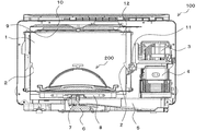
図1は実施の形態に係る高周波加熱調理器の内部を示す正面断面図である。
実施の形態に係る高周波加熱調理器100は、図1に示すように、内部の左側に加熱室1が設けられ、加熱室1の右側に電源/制御基板3、マグネトロン4などが配置されている。
FIG. 1 is a front sectional view showing the inside of the high-frequency cooking device according to the embodiment.
As shown in FIG. 1, the high-
加熱室1の前面には、被加熱物である食品、後述する加熱調理器具200の出し入れが自在の開口部が設けられている。この開口部は、一部に窓ガラスを有する扉によって開閉されるようになっている。加熱室1の左右の側壁には、食品などを載せる四辺形形状の皿を支持する皿保持部2が設けられている。
On the front surface of the
また、加熱室1の例えば右側の側壁には、加熱室1内の食品、又は加熱室1内に設置された加熱調理器具200から発する赤外線を受光し電気信号に変換する赤外線センサー11(非接触式温度検出手段)と、加熱室1内の温度に応じて電気信号に変換するサーミスタ12(温度検出手段)とが設置されている。なお、サーミスタ12を、加熱室1の側壁上部に設置しているが、これに代えて、排気ダクト内に設置してもよい。
In addition, on the right side wall of the
加熱室1の天板の裏面には、フラットヒーターからなる上ヒーター9が設置され、この上ヒーター9の上方には、断熱材10が設けられている。加熱室1の底板の下方には、シーズヒーターからなる下ヒーター8が設置されている。上ヒーター9と下ヒーター8とにより、加熱室1内を高温にし、食品を加熱することができる。また、加熱室1の底板の下方には、アンテナモーター6、アンテナモーター6の駆動により回転するアンテナ7、導波管5などが配置されている。
An upper heater 9 made of a flat heater is installed on the back surface of the top plate of the
電源/制御基板3は、商用電源の電圧を直流電圧に変換して昇圧し、昇圧した直流電圧を高周波電圧に変換してマグネトロン4に供給する。マグネトロン4は、高周波電圧の入力に基づいて高周波を発振する。アンテナ7は、前述のようにアンテナモーター6の駆動により回転しながら高周波を加熱室1内に放射し、加熱室1内に設置された食品を高周波加熱し、あるいは加熱調理器具200を高周波で発熱させる。なお、電源/制御基板3、マグネトロン4、導波管5及びアンテナ7により高周波発生手段が構成されている。
The power supply /
また、前述の電源/制御基板3は、加熱開始の指示により、マグネトロン4に高周波電圧を供給した際に、赤外線センサー11からの電気信号に基づいて食品又は加熱調理器具200の表面温度を算出し、サーミスタ12からの電気信号に基づいて加熱室1内の温度を算出して、温度の高い方を選択する。例えば、赤外線センサー11で検出された表面温度の方が高いときには、電源/制御基板3は、その表面温度が調理メニューに応じて設定された設定温度に達したかどうかを判定し、赤外線センサー11により検出された表面温度が設定温度に達したときには、食品又は加熱調理器具200内の食品における残り加熱時間を算出する。そして、電源/制御基板3は、算出した残り加熱時間が経過したときに、マグネトロン4への高周波電圧の供給を遮断し、アンテナモーター6の駆動を停止する。
The power supply /
なお、サーミスタ12で加熱室1内の温度を検出するようにしたが、そのサーミスタ12で加熱室1内の温度を検出し、検出した温度変化から加熱室1内に発生する食品からの蒸気を検出するようにしてもよい。食品又は加熱調理器具200を高周波加熱中に、加熱室1内の温度が低下したときに、食品から蒸気が発生していると見なして加熱を終了する。この場合、加熱調理器具200の蓋体30には、蒸気を抜くための穴を設ける必要がある。
また、本実施の形態では、赤外線センサー11とサーミスタ12を用いたが、赤外線センサー11のみを加熱制御に用いるようにしてもよい。
Although the
Moreover, in this Embodiment, although the
次に、加熱室1内に設置される加熱調理器具200の構成について、図2及び図3を用いて説明する。
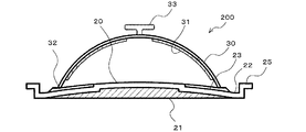
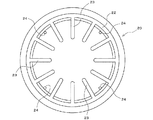
図2は実施の形態に係る加熱調理器具を示す断面図、図3は図2の加熱調理器具の蓋体を取り外した状態を示す受け皿の平面図である。
加熱調理器具200は、上方から見て円形状に形成された受け皿20と、側方から見て外形が半球面状に形成され、受け皿20の上面に着脱自在に載置される蓋体30とで構成されている。
Next, the structure of the
2 is a cross-sectional view showing the cooking device according to the embodiment, and FIG. 3 is a plan view of the saucer showing a state where the lid of the cooking device of FIG. 2 is removed.
The
受け皿20は、下面に高周波を吸収して発熱する高周波発熱体21(以下、「皿発熱体21」という)を有し、周縁部25の上面にはリング状に形成された第1溝部22が設けられている。この第1溝部22は、蓋体30の周縁部32および皿発熱体21の外周部よりも外側に位置している。受け皿20の上面は、中央部を頂点として、第1溝部22に向かうに連れて下方に傾斜している。
The
また、受け皿20の上面には、放射状に配置されて第1溝部22にそれぞれ連通する複数の第2溝部23が設けられている。また、受け皿20の上面には、第1溝部22よりも内側で、蓋体30の周縁部32よりも外側の位置に周方向に例えば4つの突起部24が配置されている。突起部24は、蓋体30を受け皿20に載せるときの位置決め用である。この突起部24により、蓋体30を受け皿20上に容易に、かつ確実に載せることができる。
In addition, a plurality of
受け皿20は、例えば、高周波を透過するセラミックにより形成されている。皿発熱体21は、高周波(例えば2.45GHz)を吸収して発熱する例えばMg、Cu、Zn等で構成される磁性材によって形成されている。
The
蓋体30は、上部に取っ手33が取り付けられており、内面に高周波発熱体31(以下、「蓋発熱体31」という)が設けられている。この蓋発熱体31は、前記と同様に、高周波を吸収して発熱するMg、Cu、Zn等で構成される磁性材によって形成されている。
The
皿発熱体21と蓋発熱体31は、前述したMg、Cu、Zn等の成分調整によって、異なる昇温停止温度が設定されている。例えば、皿発熱体21の昇温停止温度は180℃程度で、蓋発熱体31の昇温停止温度は220℃に設定されている。180℃は、一般的に食品の皿発熱体21と接触する面に焦げ目を付けることができる温度である。皿発熱体21と蓋発熱体31は、高周波によりそれぞれ昇温停止温度に達すると、材質が磁性材から非磁性材に変化し、高周波を透過させる。
The
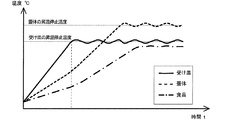
前記のように構成された加熱調理器具200を高周波加熱調理器100の高周波で発熱させるときの作用について、図1及び図4を用いて説明する。
図4は図1において高周波加熱調理器で加熱調理器具を発熱させているときの受け皿及び蓋体の各高周波発熱体の温度変化と加熱調理器具内の食品の温度変化を示す図である。
An operation when the
FIG. 4 is a diagram showing a temperature change of each high-frequency heating element of the saucer and the lid and a temperature change of food in the heating cooker when the heating cooking utensil is heated in the high-frequency heating cooker in FIG.
受け皿20に例えば肉等の食品を載せ、その食品の載った受け皿20を覆うように蓋体30を載せて、高周波加熱調理器100の加熱室1内に設置し、そして、扉を閉めた後に高周波加熱の指示を操作部の操作で行うと、電源/制御基板3が商用電源から高周波電圧を生成してマグネトロン4に供給する。マグネトロン4は、高周波電圧の入力に基づいて高周波を発振し、導波管5を介して、アンテナモーター6で回転しているアンテナ7に供給する。アンテナ7は回転しながら、高周波を加熱室1の底板の下方から加熱室1内に放射する。
After food such as meat is placed on the
アンテナ7から放射される高周波のうち、殆どの高周波は、皿発熱体21に吸収され、残りの高周波は、加熱室1の側壁(扉も含む)を反射して、蓋発熱体31と食品に吸収される。この時、皿発熱体21は、高周波の吸収量に応じて発熱し、受け皿20上の食品を下から加熱していく。また、蓋発熱体31は、高周波の吸収量に応じて発熱し、受け皿20上の食品を上方から加熱する。この場合、図4に示すように、皿発熱体21は、高周波の吸収量が多いために、蓋発熱体31と比べて、温度(実線)の上昇率が速くなり、一方、食品の温度(一点鎖線)は、蓋発熱体31の温度(破線)よりも緩く上昇していく。
Of the high frequencies radiated from the antenna 7, most of the high frequencies are absorbed by the
そして、皿発熱体21の温度が昇温停止温度(180℃)に達すると、その皿発熱体21は、磁性材から非磁性材に変化して、アンテナ7からの高周波を透過させる。この時、食品は、皿発熱体21を透過する高周波により発熱するため、食品の温度が上がっていく。一方、皿発熱体21は、高周波の透過により、温度が昇温停止温度よりも低くなると、その皿発熱体21は、非磁性材から磁性材に戻り、高周波を吸収して発熱する。つまり、皿発熱体21は、昇温停止温度を基準に、磁性材から非磁性材に変化し、逆に、非磁性材から磁性材に戻り、これを繰り返し行いながら食品を間欠的に加熱する。
When the temperature of the
一方、蓋発熱体31は、加熱室1の側壁を反射する高周波と、皿発熱体21を間欠的に透過する高周波とから、温度の上昇率が徐々に速くなる。そして、蓋発熱体31の温度が昇温停止温度(220℃)に達すると、その蓋発熱体31は、皿発熱体21と同様に、磁性材から非磁性材に変化して高周波を透過させ、高周波の透過により、温度が昇温停止温度よりも低くなると、非磁性材から磁性材に戻って、食品を間欠的に加熱する。
On the other hand, the temperature increase rate of the
食品は、蓋発熱体31が昇温停止温度(220℃)で発熱すると、昇温停止温度(180℃)で発熱している皿発熱体21と蓋発熱体31とで加熱され、略一定の温度となる(図4参照)。この加熱により、食品から脂等が出てきた場合には、その脂は、受け皿20の上面を第1溝部22に向かって流れると共に、複数の第2溝部23を通って第1溝部22に向かって流れる。
When the
以上のように実施の形態によれば、受け皿20の周縁部25の上面に設けられたリング形状の第1溝部22を、蓋体30の周縁部32および皿発熱体21の外周部よりも外側に配置している。また、受け皿20の上面が、中央部を頂点として、第1溝部22に向かうに連れて下方に傾斜し、その上面に、放射状に配置されて第1溝部22にそれぞれ連通する複数の第2溝部23を設けている。
この構成により、皿発熱体21と蓋発熱体31とで加熱された食品から出た脂等が、複数の第2溝部23を通って、皿発熱体21の外周部よりも外側に配置された第1溝部22に溜まる。これにより、高温の受け皿20によって脂等が過熱されてしまうようなことが殆ど無くなり、安全に加熱調理することができる。なお、第1溝部22に溜まった脂等の温度を赤外線センサー11で検知できるようにすることで、万が一、第1溝部22に溜まった脂等が過熱され温度が異常上昇した場合に、過熱を停止させることができ、より一層安全性を向上させることができる。
As described above, according to the embodiment, the ring-shaped
With this configuration, fat or the like from the food heated by the
また、蓋体30の内面に蓋発熱体31を設けているので、食品から蒸気が発生して蓋体30内に結露が付着しても、蓋発熱体31によって蒸発する。さらに、複数の第2溝部23を通って第1溝部22に溜まった温水が蒸発しても、第1溝部22を、蓋体30の周縁部32よりも外側に配置しているので、蓋体30内に結露が付着するようなことが殆ど無く、食品の仕上がりを向上させることができる。
In addition, since the
また、蓋体30に昇温停止する蓋発熱体31を用いているので、蓋体30の取っ手33の異常温度上昇を抑えることができ、火傷を防止できる。
Further, since the
なお、実施の形態では、蓋体30の内面に蓋発熱体31を設けたが、その蓋発熱体31が無くてもよい。このような加熱調理器具200であっても、皿発熱体21で加熱された食品から出た脂等が、複数の第2溝部23を通って、皿発熱体21の外周部よりも外側に配置された第1溝部22に溜まる。これにより、高温の受け皿20によって脂等が過熱されてしまうようなことが殆ど無くなり、安全に加熱調理することができる。
In the embodiment, the
また、第1溝部22を、蓋体30の周縁部32よりも外側に配置しているので、食品から蒸気が発生して蓋体30内に結露が付着しても、その結露水が蓋体30に沿って下方に流れ、複数の第2溝部23を通って、第1溝部22に溜まる。このため、蓋体30内の水分が減少し、食品の仕上がりを向上させることができる。
Moreover, since the
1 加熱室、2 皿保持部、3 電源/制御基板、4 マグネトロン、5 導波管、6 アンテナモーター、7 アンテナ、8 下ヒーター、9 上ヒーター、10 断熱材、11 赤外線センサー、12 サーミスタ、20 受け皿、21 皿発熱体(高周波発熱体)、22 第1溝部、23 第2溝部、24 突起部、25 周縁部、30 蓋体、31 蓋発熱体(高周波発熱体)、32 周縁部、33 取っ手、100 高周波加熱調理器、200 加熱調理器具。
DESCRIPTION OF
Claims (8)
前記受け皿の上面に着脱自在に載置される蓋体とを備え、
前記第1溝部を、前記蓋体の周縁部および前記高周波発熱体の外周部よりも外側に配置したことを特徴とする加熱調理器具。 A low-frequency heating element that absorbs high-frequency waves and generates heat on the lower surface; and a saucer having a first groove on the peripheral edge of the upper surface;
A lid that is detachably mounted on the upper surface of the tray,
The cooking device according to claim 1, wherein the first groove portion is disposed outside a peripheral portion of the lid and an outer peripheral portion of the high-frequency heating element.
前記受け皿は、上面に放射状に設けられて前記第1溝部に連通する第2溝部を備えていることを特徴とする請求項1記載の加熱調理器具。 The first groove is formed in a ring shape,
The cooking device according to claim 1, wherein the tray includes a second groove portion provided radially on an upper surface and communicating with the first groove portion.
前記受け皿の高周波発熱体は、前記蓋体の高周波発熱体よりも昇温停止温度が低いことを特徴とする請求項4記載の加熱調理器具。 The saucer is formed of a member that transmits high frequency,
The cooking device according to claim 4, wherein the high-frequency heating element of the tray has a lower temperature rise stop temperature than the high-frequency heating element of the lid.
高周波を発生し、当該高周波を前記加熱室に収納された被加熱物に放射して高周波加熱する高周波発生手段と、
前記加熱室内に出し入れ自在に設置され、内部に収納された被加熱物を加熱する加熱調理器具とを備え、
前記加熱調理器具として請求項1〜5の何れか1項に記載の加熱調理器具を用いたことを特徴とする高周波加熱調理器。 A heating chamber in which an object to be heated is freely stored and removed;
High-frequency generating means for generating a high frequency, radiating the high frequency to the object to be heated stored in the heating chamber, and heating the high frequency
A heating cooker that is installed so as to be freely put in and out of the heating chamber and that heats an object to be heated housed therein;
A high-frequency cooking device using the cooking device according to any one of claims 1 to 5 as the cooking device.
前記状態検出手段の検出に基づいて加熱制御することを特徴とする請求項6記載の高周波加熱調理器。 At least a non-contact type temperature detecting means for detecting the temperature of the cooking device without contact, a steam detecting means for detecting steam generated from the inside of the cooking device, and a temperature detecting means for detecting the temperature in the heating chamber Including any one state detection means;
The high-frequency heating cooker according to claim 6, wherein heating control is performed based on detection by the state detection means.
Priority Applications (1)
| Application Number | Priority Date | Filing Date | Title |
|---|---|---|---|
| JP2013255249A JP2015114017A (en) | 2013-12-10 | 2013-12-10 | Heating cooker and high frequency heating cooker |
Applications Claiming Priority (1)
| Application Number | Priority Date | Filing Date | Title |
|---|---|---|---|
| JP2013255249A JP2015114017A (en) | 2013-12-10 | 2013-12-10 | Heating cooker and high frequency heating cooker |
Publications (1)
| Publication Number | Publication Date |
|---|---|
| JP2015114017A true JP2015114017A (en) | 2015-06-22 |
Family
ID=53527992
Family Applications (1)
| Application Number | Title | Priority Date | Filing Date |
|---|---|---|---|
| JP2013255249A Pending JP2015114017A (en) | 2013-12-10 | 2013-12-10 | Heating cooker and high frequency heating cooker |
Country Status (1)
| Country | Link |
|---|---|
| JP (1) | JP2015114017A (en) |
Cited By (1)
| Publication number | Priority date | Publication date | Assignee | Title |
|---|---|---|---|---|
| CN108332243A (en) * | 2018-02-26 | 2018-07-27 | 广东美的厨房电器制造有限公司 | Micro-wave oven |
-
2013
- 2013-12-10 JP JP2013255249A patent/JP2015114017A/en active Pending
Cited By (1)
| Publication number | Priority date | Publication date | Assignee | Title |
|---|---|---|---|---|
| CN108332243A (en) * | 2018-02-26 | 2018-07-27 | 广东美的厨房电器制造有限公司 | Micro-wave oven |
Similar Documents
| Publication | Publication Date | Title |
|---|---|---|
| CN212678957U (en) | Cooking system | |
| CN212368782U (en) | Cooking apparatus | |
| CN101903705B (en) | Cooker | |
| US10022021B2 (en) | Cooking apparatus | |
| CN102265092B (en) | Microwave heating cooker | |
| JP6109207B2 (en) | Temperature sensor probe and cooking device | |
| WO2018025095A1 (en) | Cooking apparatus | |
| JP4000531B2 (en) | Cooker | |
| CN111281113B (en) | Cooking method for a cooking appliance and cooking appliance | |
| KR101269345B1 (en) | Lid assembly for cooking or keeping warm food | |
| JP5492646B2 (en) | Induction heating cooker | |
| JP6768464B2 (en) | Temperature detector and cooker | |
| JP2015114017A (en) | Heating cooker and high frequency heating cooker | |
| JP6109133B2 (en) | Temperature sensor probe, cooking device | |
| JP2017107766A (en) | Induction heating cooker | |
| KR20170025601A (en) | Portable microwave ovens for cooking food and the control method thereof | |
| JP2014088968A (en) | High-frequency heating device | |
| JP2008067997A (en) | High frequency heating device | |
| CN111281115B (en) | Cooking method for a cooking appliance and cooking appliance | |
| KR20110073659A (en) | Microwave Rice Cooker | |
| JP7792562B2 (en) | High frequency heating cooker | |
| JP2006334132A (en) | Cooker | |
| JP7524092B2 (en) | Cooking equipment | |
| JP5923406B2 (en) | Cooker | |
| CN111281116B (en) | Cooking method for a cooking appliance and cooking appliance |