JP2015114010A - Air conditioner - Google Patents
Air conditioner Download PDFInfo
- Publication number
- JP2015114010A JP2015114010A JP2013254998A JP2013254998A JP2015114010A JP 2015114010 A JP2015114010 A JP 2015114010A JP 2013254998 A JP2013254998 A JP 2013254998A JP 2013254998 A JP2013254998 A JP 2013254998A JP 2015114010 A JP2015114010 A JP 2015114010A
- Authority
- JP
- Japan
- Prior art keywords
- heat exchanger
- refrigerant
- air conditioner
- outdoor
- receiver
- Prior art date
- Legal status (The legal status is an assumption and is not a legal conclusion. Google has not performed a legal analysis and makes no representation as to the accuracy of the status listed.)
- Pending
Links
Images
Classifications
-
- F—MECHANICAL ENGINEERING; LIGHTING; HEATING; WEAPONS; BLASTING
- F24—HEATING; RANGES; VENTILATING
- F24F—AIR-CONDITIONING; AIR-HUMIDIFICATION; VENTILATION; USE OF AIR CURRENTS FOR SCREENING
- F24F1/00—Room units for air-conditioning, e.g. separate or self-contained units or units receiving primary air from a central station
- F24F1/06—Separate outdoor units, e.g. outdoor unit to be linked to a separate room comprising a compressor and a heat exchanger
- F24F1/36—Drip trays for outdoor units
-
- F—MECHANICAL ENGINEERING; LIGHTING; HEATING; WEAPONS; BLASTING
- F24—HEATING; RANGES; VENTILATING
- F24F—AIR-CONDITIONING; AIR-HUMIDIFICATION; VENTILATION; USE OF AIR CURRENTS FOR SCREENING
- F24F1/00—Room units for air-conditioning, e.g. separate or self-contained units or units receiving primary air from a central station
- F24F1/06—Separate outdoor units, e.g. outdoor unit to be linked to a separate room comprising a compressor and a heat exchanger
- F24F1/42—Separate outdoor units, e.g. outdoor unit to be linked to a separate room comprising a compressor and a heat exchanger characterised by the use of the condensate, e.g. for enhanced cooling
-
- F—MECHANICAL ENGINEERING; LIGHTING; HEATING; WEAPONS; BLASTING
- F24—HEATING; RANGES; VENTILATING
- F24F—AIR-CONDITIONING; AIR-HUMIDIFICATION; VENTILATION; USE OF AIR CURRENTS FOR SCREENING
- F24F1/00—Room units for air-conditioning, e.g. separate or self-contained units or units receiving primary air from a central station
- F24F1/06—Separate outdoor units, e.g. outdoor unit to be linked to a separate room comprising a compressor and a heat exchanger
- F24F1/46—Component arrangements in separate outdoor units
-
- F—MECHANICAL ENGINEERING; LIGHTING; HEATING; WEAPONS; BLASTING
- F25—REFRIGERATION OR COOLING; COMBINED HEATING AND REFRIGERATION SYSTEMS; HEAT PUMP SYSTEMS; MANUFACTURE OR STORAGE OF ICE; LIQUEFACTION SOLIDIFICATION OF GASES
- F25B—REFRIGERATION MACHINES, PLANTS OR SYSTEMS; COMBINED HEATING AND REFRIGERATION SYSTEMS; HEAT PUMP SYSTEMS
- F25B13/00—Compression machines, plants or systems, with reversible cycle
-
- F—MECHANICAL ENGINEERING; LIGHTING; HEATING; WEAPONS; BLASTING
- F25—REFRIGERATION OR COOLING; COMBINED HEATING AND REFRIGERATION SYSTEMS; HEAT PUMP SYSTEMS; MANUFACTURE OR STORAGE OF ICE; LIQUEFACTION SOLIDIFICATION OF GASES
- F25B—REFRIGERATION MACHINES, PLANTS OR SYSTEMS; COMBINED HEATING AND REFRIGERATION SYSTEMS; HEAT PUMP SYSTEMS
- F25B41/00—Fluid-circulation arrangements
- F25B41/30—Expansion means; Dispositions thereof
- F25B41/39—Dispositions with two or more expansion means arranged in series, i.e. multi-stage expansion, on a refrigerant line leading to the same evaporator
-
- F—MECHANICAL ENGINEERING; LIGHTING; HEATING; WEAPONS; BLASTING
- F25—REFRIGERATION OR COOLING; COMBINED HEATING AND REFRIGERATION SYSTEMS; HEAT PUMP SYSTEMS; MANUFACTURE OR STORAGE OF ICE; LIQUEFACTION SOLIDIFICATION OF GASES
- F25B—REFRIGERATION MACHINES, PLANTS OR SYSTEMS; COMBINED HEATING AND REFRIGERATION SYSTEMS; HEAT PUMP SYSTEMS
- F25B49/00—Arrangement or mounting of control or safety devices
- F25B49/02—Arrangement or mounting of control or safety devices for compression type machines, plants or systems
-
- F—MECHANICAL ENGINEERING; LIGHTING; HEATING; WEAPONS; BLASTING
- F25—REFRIGERATION OR COOLING; COMBINED HEATING AND REFRIGERATION SYSTEMS; HEAT PUMP SYSTEMS; MANUFACTURE OR STORAGE OF ICE; LIQUEFACTION SOLIDIFICATION OF GASES
- F25B—REFRIGERATION MACHINES, PLANTS OR SYSTEMS; COMBINED HEATING AND REFRIGERATION SYSTEMS; HEAT PUMP SYSTEMS
- F25B2313/00—Compression machines, plants or systems with reversible cycle not otherwise provided for
- F25B2313/006—Compression machines, plants or systems with reversible cycle not otherwise provided for two pipes connecting the outdoor side to the indoor side with multiple indoor units
-
- F—MECHANICAL ENGINEERING; LIGHTING; HEATING; WEAPONS; BLASTING
- F25—REFRIGERATION OR COOLING; COMBINED HEATING AND REFRIGERATION SYSTEMS; HEAT PUMP SYSTEMS; MANUFACTURE OR STORAGE OF ICE; LIQUEFACTION SOLIDIFICATION OF GASES
- F25B—REFRIGERATION MACHINES, PLANTS OR SYSTEMS; COMBINED HEATING AND REFRIGERATION SYSTEMS; HEAT PUMP SYSTEMS
- F25B2313/00—Compression machines, plants or systems with reversible cycle not otherwise provided for
- F25B2313/027—Compression machines, plants or systems with reversible cycle not otherwise provided for characterised by the reversing means
- F25B2313/02741—Compression machines, plants or systems with reversible cycle not otherwise provided for characterised by the reversing means using one four-way valve
-
- F—MECHANICAL ENGINEERING; LIGHTING; HEATING; WEAPONS; BLASTING
- F25—REFRIGERATION OR COOLING; COMBINED HEATING AND REFRIGERATION SYSTEMS; HEAT PUMP SYSTEMS; MANUFACTURE OR STORAGE OF ICE; LIQUEFACTION SOLIDIFICATION OF GASES
- F25B—REFRIGERATION MACHINES, PLANTS OR SYSTEMS; COMBINED HEATING AND REFRIGERATION SYSTEMS; HEAT PUMP SYSTEMS
- F25B2400/00—Component parts or details not otherwise provided for in this subclass
- F25B2400/04—Refrigeration circuit bypassing means
- F25B2400/0415—Refrigeration circuit bypassing means for receivers
-
- F—MECHANICAL ENGINEERING; LIGHTING; HEATING; WEAPONS; BLASTING
- F25—REFRIGERATION OR COOLING; COMBINED HEATING AND REFRIGERATION SYSTEMS; HEAT PUMP SYSTEMS; MANUFACTURE OR STORAGE OF ICE; LIQUEFACTION SOLIDIFICATION OF GASES
- F25B—REFRIGERATION MACHINES, PLANTS OR SYSTEMS; COMBINED HEATING AND REFRIGERATION SYSTEMS; HEAT PUMP SYSTEMS
- F25B2400/00—Component parts or details not otherwise provided for in this subclass
- F25B2400/05—Compression system with heat exchange between particular parts of the system
- F25B2400/053—Compression system with heat exchange between particular parts of the system between the storage receiver and another part of the system
-
- F—MECHANICAL ENGINEERING; LIGHTING; HEATING; WEAPONS; BLASTING
- F25—REFRIGERATION OR COOLING; COMBINED HEATING AND REFRIGERATION SYSTEMS; HEAT PUMP SYSTEMS; MANUFACTURE OR STORAGE OF ICE; LIQUEFACTION SOLIDIFICATION OF GASES
- F25B—REFRIGERATION MACHINES, PLANTS OR SYSTEMS; COMBINED HEATING AND REFRIGERATION SYSTEMS; HEAT PUMP SYSTEMS
- F25B2600/00—Control issues
- F25B2600/05—Refrigerant levels
-
- F—MECHANICAL ENGINEERING; LIGHTING; HEATING; WEAPONS; BLASTING
- F25—REFRIGERATION OR COOLING; COMBINED HEATING AND REFRIGERATION SYSTEMS; HEAT PUMP SYSTEMS; MANUFACTURE OR STORAGE OF ICE; LIQUEFACTION SOLIDIFICATION OF GASES
- F25B—REFRIGERATION MACHINES, PLANTS OR SYSTEMS; COMBINED HEATING AND REFRIGERATION SYSTEMS; HEAT PUMP SYSTEMS
- F25B2700/00—Sensing or detecting of parameters; Sensors therefor
- F25B2700/02—Humidity
-
- F—MECHANICAL ENGINEERING; LIGHTING; HEATING; WEAPONS; BLASTING
- F25—REFRIGERATION OR COOLING; COMBINED HEATING AND REFRIGERATION SYSTEMS; HEAT PUMP SYSTEMS; MANUFACTURE OR STORAGE OF ICE; LIQUEFACTION SOLIDIFICATION OF GASES
- F25B—REFRIGERATION MACHINES, PLANTS OR SYSTEMS; COMBINED HEATING AND REFRIGERATION SYSTEMS; HEAT PUMP SYSTEMS
- F25B2700/00—Sensing or detecting of parameters; Sensors therefor
- F25B2700/21—Temperatures
- F25B2700/2104—Temperatures of an indoor room or compartment
Landscapes
- Engineering & Computer Science (AREA)
- Mechanical Engineering (AREA)
- General Engineering & Computer Science (AREA)
- Physics & Mathematics (AREA)
- Thermal Sciences (AREA)
- Chemical & Material Sciences (AREA)
- Combustion & Propulsion (AREA)
- Air Conditioning Control Device (AREA)
- Other Air-Conditioning Systems (AREA)
Abstract
Description
本発明は、冷媒回路を循環する冷媒量を調整可能な空気調和機に関する。 The present invention relates to an air conditioner capable of adjusting the amount of refrigerant circulating in a refrigerant circuit.
現在の空気調和機のほとんどは、冷房と暖房が切り替えられるように冷媒回路が構成されている。また、冷媒回路に必要な冷媒量は、凝縮器の大きさによって大きく変化するところ、一般的な空気調和機においては、冷媒回路を構成する室内熱交換器と室外熱交換器とで冷媒流路の容積が異なる。したがって、冷房運転時と暖房運転時とで、冷媒回路に必要とされる冷媒量が大きく変化する。冷媒回路に必要とされる冷媒量と、実際に冷媒回路を循環する冷媒量との差が大きくなるほど、空気調和機の運転の効率が低下する。 Most current air conditioners have a refrigerant circuit configured to switch between cooling and heating. Also, the amount of refrigerant required for the refrigerant circuit varies greatly depending on the size of the condenser. In a general air conditioner, the refrigerant flow path between the indoor heat exchanger and the outdoor heat exchanger that constitute the refrigerant circuit The volume of is different. Therefore, the amount of refrigerant required for the refrigerant circuit varies greatly between the cooling operation and the heating operation. The greater the difference between the amount of refrigerant required for the refrigerant circuit and the amount of refrigerant that actually circulates in the refrigerant circuit, the lower the efficiency of operation of the air conditioner.
上記課題に対して、特許文献1には、少なくとも1つの冷媒ラインによって冷媒回路と流通連通して接続される冷媒貯蔵装置(レシーバ)と、少なくとも1つの冷媒ラインに配された冷媒流制御装置とを備え、冷媒流制御装置は、冷媒が冷媒ラインを通流する開位置と、冷媒ラインを通る冷媒の流れを遮断する閉位置とを有する冷媒蒸気圧縮システムが記載されている。特許文献1では、冷媒流制御装置の開閉を制御することで、冷媒回路内の冷媒量を調整可能としている。
In response to the above problem,
上述のように、特許文献1では、冷媒制御装置の開閉制御が必要とされていた。
そこで、本発明においては、上記に鑑み、構造が複雑化することなく、レシーバを用いて冷媒量調整を容易に行なうことが可能で、運転効率の高い空気調和機を提供することを目的とする。
As described above, in
Therefore, in view of the above, an object of the present invention is to provide an air conditioner that can easily adjust the amount of refrigerant using a receiver without complicating the structure and has high operating efficiency. .
上記目的を達成するために、本発明では、圧縮機、室内熱交換器、絞り装置及び室外熱交換器を含む冷媒回路と、冷媒を溜めるレシーバと、前記冷媒回路及びレシーバを連結する連結管とを備えた空気調和機であって、前記連結管は、一端側が、前記レシーバの出入口に接続され、他端側が、前記冷媒回路において、冷房運転時に圧縮機から吐出した高圧冷媒の少なくとも一部が液相として存在するエリアに接続され、前記レシーバは、冷房運転時に室内熱交換器から圧縮機に冷媒が流れる配管と熱交換可能なように設けられたことを特徴とする。 In order to achieve the above object, in the present invention, a refrigerant circuit including a compressor, an indoor heat exchanger, an expansion device, and an outdoor heat exchanger, a receiver that stores the refrigerant, and a connecting pipe that connects the refrigerant circuit and the receiver. The connecting pipe has one end connected to the inlet / outlet of the receiver and the other end connected to the refrigerant circuit, and at least a part of the high-pressure refrigerant discharged from the compressor during cooling operation is provided in the refrigerant pipe. The receiver is connected to an area existing as a liquid phase, and the receiver is provided so that heat can be exchanged with a pipe through which a refrigerant flows from the indoor heat exchanger to the compressor during cooling operation.
上記構成によれば、冷房運転時において、レシーバとの間で熱交換可能に設けられる配管(以下、熱交換配管)を流れる冷媒温度は、連結管を通ってレシーバに導入される、液相と気相とが混在した過冷却状態の高圧冷媒温度よりも低温となる。従って、レシーバ内に導入された冷媒は冷却され、液化した状態でレシーバに貯蔵することが可能となる。また、暖房運転時は、熱交換配管は、圧縮機から吐出された高温高圧のガス状の冷媒が通過するため、レシーバも加熱されて高温となる。これによって、レシーバ内の冷媒はガス状となるため、レシーバ内の冷媒を冷媒回路に戻すことが可能となる。 According to the above configuration, during the cooling operation, the temperature of the refrigerant flowing through a pipe (hereinafter referred to as a heat exchange pipe) provided so as to be able to exchange heat with the receiver is introduced into the receiver through the connecting pipe, The temperature is lower than the supercooled high-pressure refrigerant temperature mixed with the gas phase. Therefore, the refrigerant introduced into the receiver is cooled and can be stored in the receiver in a liquefied state. Further, during the heating operation, since the high-temperature and high-pressure gaseous refrigerant discharged from the compressor passes through the heat exchange pipe, the receiver is also heated to a high temperature. Thereby, since the refrigerant in the receiver is in a gaseous state, the refrigerant in the receiver can be returned to the refrigerant circuit.
本発明は、設計上の理由により、冷房運転時に冷媒回路を循環する冷媒の最適量(最適冷媒量)が、暖房運転時の最適冷媒量よりも少なくなるようなケースにおいて、好適に適用される。すなわち、上記ケースにおいて、本発明の構成を採用することで、運転モード(冷暖房運転)に応じて、冷媒回路を循環する冷媒量(循環冷媒量)を自動的に調整して運転効率に優れた空気調和機を提供することが可能となる。 The present invention is preferably applied to a case where the optimum amount of refrigerant circulating through the refrigerant circuit during cooling operation (optimum refrigerant amount) is smaller than the optimum refrigerant amount during heating operation due to design reasons. . That is, in the above case, by adopting the configuration of the present invention, the refrigerant quantity (circulating refrigerant quantity) circulating in the refrigerant circuit is automatically adjusted according to the operation mode (air-conditioning operation), and the operation efficiency is excellent. An air conditioner can be provided.
ここで、最適冷媒量とは、「空調能力」/「消費電力」で表わされるCOP(成績係数)が最大となる冷媒量を意味する。冷房運転と暖房運転とで最適冷媒量を比較する場合、冷暖房運転とも定格運転を行ったときの最適冷媒量を比較することができる。また、定格運転とは、圧縮機の回転数を予め設定した一定値で駆動させる運転を意味する。圧縮機の回転数としては、最小回転数と最大回転数の間の、運転効率が高く標準的な回転数が設定される。 Here, the optimum refrigerant amount means the refrigerant amount that maximizes the COP (coefficient of performance) represented by “air conditioning capacity” / “power consumption”. When the optimum refrigerant amount is compared between the cooling operation and the heating operation, it is possible to compare the optimum refrigerant amount when the rated operation is performed for both the cooling and heating operation. The rated operation means an operation in which the rotation speed of the compressor is driven at a preset constant value. As the rotation speed of the compressor, a standard rotation speed with high operation efficiency between the minimum rotation speed and the maximum rotation speed is set.
上述のように、本発明によれば、冷媒回路において、冷房運転時に圧縮機から吐出した高圧冷媒の少なくとも一部が液相として存在するエリアに冷媒を溜めるレシーバを接続するとともに、冷房運転時に室内熱交換器から圧縮機に冷媒が流れる配管と熱交換可能なように設けたため、自動的に冷房運転時にはレシーバ内に冷媒を溜め、暖房運転時にはレシーバ内の冷媒を冷媒回路に戻すことが可能となる。したがって、冷房運転時の方が暖房運転時よりも最適冷媒量が少なくなるタイプの空気調和機において、運転効率の高い空気調和機を得ることができる。 As described above, according to the present invention, in the refrigerant circuit, the receiver that stores the refrigerant is connected to an area in which at least a part of the high-pressure refrigerant discharged from the compressor during the cooling operation exists as a liquid phase, Since heat exchange with the pipe through which the refrigerant flows from the heat exchanger to the compressor is possible, the refrigerant can be automatically stored in the receiver during cooling operation, and the refrigerant in the receiver can be returned to the refrigerant circuit during heating operation. Become. Therefore, an air conditioner with high operating efficiency can be obtained in the type of air conditioner in which the optimum refrigerant amount is smaller during cooling operation than during heating operation.
[第1実施形態]
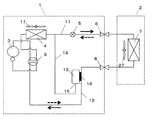
以下、図面に基づいて本発明の実施の形態を説明する。図1は、本発明に係る空気調和機の実施形態を示す冷媒回路図である。図示のごとく、本実施形態の空気調和機は、室内機と室外機が、細管、太管で連結されたセパレート型空気調和機である。より具体的には、1台の室外機1に1台の室内機2が接続されたシングル型空気調和機であり、室外機1に収容される圧縮機3、室外熱交換器4及び絞り装置5をこの順に冷媒配管で直列に接続している。
[First Embodiment]
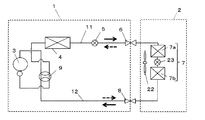
Hereinafter, embodiments of the present invention will be described with reference to the drawings. FIG. 1 is a refrigerant circuit diagram showing an embodiment of an air conditioner according to the present invention. As illustrated, the air conditioner of the present embodiment is a separate air conditioner in which an indoor unit and an outdoor unit are connected by a thin tube and a thick tube. More specifically, it is a single-type air conditioner in which one
さらに、絞り装置5から二方弁6を介して、室内機2に収容される室内熱交換器7を配管接続し、室内熱交換器7から三方弁8を介して、再び室外の圧縮機3に配管接続して冷媒回路を構成している。絞り装置5は、冷媒の流量を調整する装置であり、本実施形態では電動膨張弁が用いられているが、これに限らずキャピラリチューブを用いることもできる。
Furthermore, the
圧縮機3は、切換弁である四方弁9を介して冷媒回路に接続されており、四方弁9を切り換えることにより、室外熱交換器4側、又は、室内熱交換器7側のいずれの方向へも圧縮した冷媒を送出可能な構成とされている。この四方弁9の切り換えにより、室外熱交換器4と室内熱交換器7とが、凝縮器又は蒸発器として使用される。
The compressor 3 is connected to the refrigerant circuit via a four-
具体的に、図1では、圧縮機3から吐出される高温の冷媒が、図示する実線矢印方向に流通され、凝縮器としての室外熱交換器4、絞り装置5を経て蒸発器としての室内熱交換器7に流入されることによって冷房運転が実現される。また、圧縮機3から吐出される冷媒が、図示する破線矢印方向に流通され、凝縮器としての室内熱交換器7、絞り装置5を経て蒸発器としての室外熱交換器4に流入されることによって暖房運転が実現される。
Specifically, in FIG. 1, the high-temperature refrigerant discharged from the compressor 3 is circulated in the direction indicated by the solid line in the figure, and passes through the
本発明では、冷媒を溜めるレシーバ13が連結管14を介して上記冷媒回路に接続される。レシーバ13の底面に出入口15が下向きに形成される。連結管14は少なくとも一端側が上向きに配置され、その上端が出入口15からレシーバ13内に挿入される。連結管14の他端側は、冷媒回路において、冷房運転時に圧縮機3から吐出した高圧冷媒の少なくとも一部が液相として存在する、すなわち、冷媒が過冷却状態で存在するエリアに接続される。本実施形態では、連結管14の他端側は、室外熱交換器4と絞り装置5とをつなぐ配管11に接続される。このとき、連結管14の他端側の端部は、連結管14の一端側の端部よりも水平以上の上方にならないように冷媒回路に接続する。連結管内に冷媒やオイルが溜まるトラップが生じないようにするためである。
In the present invention, the
室内熱交換器7と圧縮機3(四方弁9)とは、三方弁8を介して配管接続される。レシーバ13は、室内熱交換器7と圧縮機3とを接続する配管の中でも、三方弁8と四方弁9とを接続する配管12に対して銅のろう材16によって溶接される。これにより、レシーバ13と配管12との間で熱交換が可能となる。なお、レシーバ13は、配管12と熱交換可能なように設ければよい。
The
ここで、熱交換可能なように設けるとは、レシーバ13と、配管12との間で熱交換可能なように、両者を直接的又は間接的に接触させることを意味する。具体的には、レシーバ13を配管12に溶接するほかに、レシーバ13に配管12が密着可能な凹面を形成し、両者をバンド等の固定具によって直接的に接触させた状態で固定する方法を例示することができる。
Here, providing so that heat exchange is possible means making both contact directly or indirectly so that heat exchange is possible between the
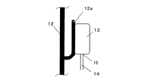
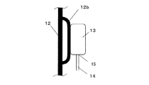
さらに、レシーバ13と配管12とを熱交換可能にする例として、レシーバ13を配管12本体に接触させるだけでなく、例えば、図2に示すように、配管12から先端を閉塞した支管12aを分岐させ、支管12aにレシーバ13を接触さてもよいし、図3に示すように、配管12の一部に、配管12に対して並列的に接続されたバイパス管12bを設け、バイパス管12bにレシーバ13を接触させるようにしてもよい。
Furthermore, as an example of enabling heat exchange between the
配管12に支管12aやバイパス管12bを設けることにより、室外機1内における配管12の位置に関係なく、レシーバ13の設置位置を決めることができ、設計上の自由度を高めることができる。なお、配管12に支管12aを設ける場合、支管12aは基端から先端に向けて水平よりも上向きになるようにする。熱交換して液化した冷媒が、支管12a内に溜まることなく、配管12に戻るようにするためである。
By providing the
本実施形態では、室外熱交換器4の容量が室内熱交換器7の容量より小さくなるように設計されている。従って、暖房運転時には、冷房運転時より多くの冷媒が必要となる。この場合、暖房定格運転時の最適冷媒量は冷房定格運転時の最適冷媒量よりも多くなる。すなわち、冷房運転および除湿運転が最適冷媒量の少ない空調運転、暖房運転が最適冷媒量の多い空調運転とされる。
In this embodiment, the capacity of the
上記構成において、冷房運転を行なうと、圧縮機3から吐出された高温高圧のガス状の冷媒は、室外熱交換器4を通過する間に気相と液相とが混在する過冷却状態となり、大部分はそのまま絞り装置5を通過するが、一部は連結管14を介してレシーバ13内に導入される。
In the above configuration, when the cooling operation is performed, the high-temperature and high-pressure gaseous refrigerant discharged from the compressor 3 is in a supercooled state in which a gas phase and a liquid phase are mixed while passing through the
絞り装置5、室内熱交換器7の順に通過した冷媒は、低温低圧のガスの状態配管12を通過する。そうすると、レシーバ13は、配管12との熱交換によってレシーバ13に導入される過冷却状態の冷媒よりも低温となる。したがって、レシーバ13内に導入された冷媒は冷却され、液化した状態でレシーバ13に貯蔵される。これにより、冷房運転時には、循環冷媒量を少なくすることができる。
The refrigerant that has passed through the
一方、暖房運転時には、配管12は、圧縮機3から吐出された高温高圧のガス状の冷媒が通過するため、レシーバ13も加熱されて高温となる。これによって、レシーバ13内の冷媒はガス状として存在するため、レシーバ13内に冷媒を溜めずに冷媒回路に戻すことが可能となる。これにより、暖房運転時には、循環冷媒量を多くすることができる。
On the other hand, during the heating operation, since the high-temperature and high-pressure gaseous refrigerant discharged from the compressor 3 passes through the
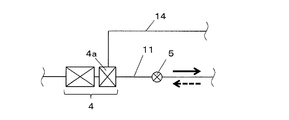
なお、本実施形態では、配管11に連結管14の他端側が接続されているが、これに限定されるものではなく、例えば、図4に示すように、室外熱交換器4の下流側に形成される過冷却領域4aに接続することも可能である。このような形態にする事により、過冷却は熱交換器4の内、レシーバに冷媒が溜まりきるまで、レシーバ以降の4aに過冷却が集中する。熱交換量は、冷媒がガス状態又は2相状態の場合に大きくなる。つまり、熱交換器4のうち、熱交換器入り口からレシーバまでの間は、過熱、または2相状態となり、熱交換能力を十分に発揮する事ができる。
In the present embodiment, the other end side of the connecting
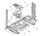
一般的に、フィンアンドチューブ型熱交換器は、等間隔に平行に並べられた多数の放熱フィンと、放熱フィンを貫通する複数段の冷媒管とを有し、冷媒管の端部はU字管によって連結された構造とされる。室外熱交換器4の過冷却領域4aにおいて連結管14を接続する場合には、U字管に連結管14の他端側を接続すればよい。
Generally, a fin-and-tube heat exchanger has a large number of heat radiation fins arranged in parallel at equal intervals and a plurality of stages of refrigerant pipes that penetrate the heat radiation fins, and the end of the refrigerant pipe is U-shaped. The structure is connected by a tube. When connecting the connecting
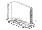
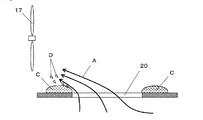
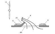
図5〜図7に示すように、室外機1内には室外機1に外気を取り入れて室外熱交換器4を通過させた後、機外に送出する室外ファン17が設置される。なお、図示しない室外機のキャビネットには吸込口及び吹出口が形成され、吸込口と吹出口の間に室外熱交換器4と室外ファン17がこの順に配置される。室外機の底板18には、室外熱交換器4から滴下した凝縮水Cを集める凹部19が形成され、凹部19の底面には凝縮水Cを室外機1の外部に排水する排水口20が形成される。
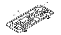
As shown in FIG. 5 to FIG. 7, an
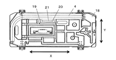
より具体的には、底板18は前後方向Yの長さよりも左右方向Xの長さが長い略矩形形状に形成される。室外熱交換器4は、略L字形状に形成され、室外熱交換器4の長辺部が左右方向Xに平行になるようにして、底板18に設置される。室外熱交換器4の長辺部の前側に室外ファン17が設置される。また、排水口20は、長孔形状に形成され、長縁部が底板18の左右方向Xに沿うように配置される。
More specifically, the
上記構成において、凹部19及び排水口20の少なくとも一方の周縁部の一部に、凹部19に溜まった凝縮水Cの飛散を防止する飛散防止壁21を形成する。これにより、凝縮水Cが微小な水滴Dとして飛散して室外ファン17や室外熱交換器4に付着するのを抑制することが可能となる。また、室外機外へ吹き出されるのを抑制することができる。なお、本実施形態では、排水口20の周縁部の一部に飛散防止壁21を形成している。
In the above configuration, the
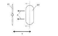
飛散防止壁21について詳述すると、飛散防止壁21は、排水口20の周縁部全体のうち、室外ファン17に近い側の部分に形成される。室外ファン17に近い側とは、図8に示すように、排水口20を長手方向の中心線(一点鎖線)によって底板18の前後方向Yの前側と後側とに二等分したときの前側(一点鎖線で分割された矢印側)を意味する。
The
凝縮水Cが飛散するメカニズムについて説明すると、図9に示すように、凹部19に集められた凝縮水Cは、所定量に達するまでは、水の表面張力により、排水口20の周縁部に盛り上がった状態で保持される。その状態で、室外ファン17が稼動すると、排水口20から室外ファン17に向かう空気流Aが発生する(図8及び図9参照)。
The mechanism by which the condensed water C scatters will be described. As shown in FIG. 9, the condensed water C collected in the
このとき、空気流Aは、排水口20の周縁部の中でも、室外ファン17に近い側の周縁部(排水口20の前縁部)において盛り上がった凝縮水Cと正面から衝突するため、この部分の凝縮水Cが水滴Dとなって飛散する。これにより、水滴Dが室外ファン17や室外熱交換器4に付着し、氷結することで、室外ファン17が破損したり、室外熱交換器4の熱交換器性能が低下するといった問題が生じる。また、室外機外へ吹き出されてしまうことがある。
At this time, the air flow A collides from the front with the condensate C that has risen in the peripheral edge (the front edge of the drain outlet 20) on the side close to the
一方、飛散防止壁21を排水口20の周縁部全体のうち、前縁部の部分に形成すると、図10に示すように、飛散防止壁21によって凝縮水Cが空気流Aに曝されるのを回避することができるため、凝縮水Cの飛散を効果的に抑制することが可能となる。本実施形態では、飛散防止壁21は、排水口20の前縁部のうち、左右方向Xに平行に形成された直線部分いっぱいに形成されている。
On the other hand, when the
なお、排水口20の形成位置は、図6に示すように、底板18を平面視したときに、排水口20の前縁部の少なくとも一部が、室外熱交換器4の長辺部の前端部よりも前方に位置するようにするのが好ましい。これによって、水滴Dが飛散した場合であっても、室外熱交換器4への付着を抑制することができる。また、凹部19や排水口20が複数設けられた場合でも、上述のようにして、凹部19及び/又は排水口20ごとに飛散防止壁21を形成すればよい。
As shown in FIG. 6, when the
飛散防止壁21は、排水口20の半径方向内側に向けて突設する(飛散防止壁21が凹部の周縁部に設けられる場合は、凹部の半径方向内側に向けて突設する)か、あるいは、排水口(又は凹部)の上方に向けて突設するのが好ましい。さらに、排水口20の半径方向内側に向けて上方に突設する、すなわち、斜め上方に傾斜して形成するのがより好ましい(図10参照)。このとき、斜め上方とする場合は、30°以上で45°前後がよい。
The
飛散防止壁21は、排水口20の周縁部に形成するだけでなく、例えば、他の形態として、図11に示すように、凹部19の周縁部に形成することも可能である。この場合、飛散防止壁21は、凹部の周縁部全体のうち、室外ファン17に近い側の部分(前側部分)において、凹部の半径方向内側に向けて突設すればよい。なお、飛散防止壁21を凹部19の周縁部に設ける場合、その目的は排水口20の周縁部から飛散した水滴Dを飛散防止壁21で遮断し、室外ファン17や室外熱交換器4に付着するのを防止することにある。
The
よって、この場合の飛散防止壁21は、凹部19の一部を覆うように、水平方向に突設すればよい。なお、飛散防止壁21は、排水口の周縁部又は凹部の周縁部のいずれか一方に形成してもよいし、排水口の周縁部及び凹部の周縁部の両方に形成することも可能である。
Therefore, the
飛散防止壁21は、底板18と別体に形成し、底板18に取り付けることができる。そのほか、飛散防止壁21を排水口20の周縁部に形成する場合には、飛散防止壁21を、底板18の排水口を打ち抜き加工する際に、一部を抜き残すことにより底板18と一体的に形成することも可能である。この場合、飛散防止壁21を上方に屈曲することで切起片とするのが好ましい。上記構成によれば、飛散防止壁を底板と別体に設ける場合に比べて、飛散防止壁を作製する工程、及び、飛散防止壁を底板に取り付ける工程を省略することができ、生産性を高めることが可能となる。
The
本発明の空気調和機は、圧縮機、室内熱交換器、絞り装置及び室外熱交換器を含む冷媒回路を備え、前記圧縮機、室外熱交換器及び絞り装置が室外機に収容され、前記室外機の底板に、前記室外熱交換器から滴下した凝縮水を集める凹部が形成され、前記凹部の底面に排水口が形成され、前記凹部及び排水口の少なくとも一方の周縁部の一部に、凹部に溜まった凝縮水の飛散を防止する飛散防止壁が形成された構成とすることができる。 The air conditioner of the present invention includes a refrigerant circuit including a compressor, an indoor heat exchanger, a throttling device, and an outdoor heat exchanger, and the compressor, the outdoor heat exchanger, and the throttling device are accommodated in an outdoor unit, and the outdoor unit A recess for collecting condensed water dripped from the outdoor heat exchanger is formed on the bottom plate of the machine, a drain outlet is formed on the bottom surface of the recess, and a recess is formed in a part of the peripheral edge of at least one of the recess and the drain outlet. It can be set as the structure in which the scattering prevention wall which prevents scattering of the condensed water accumulated in was formed.
[第2実施形態]
本実施形態に係る発明は、再熱除湿可能な空気調和機に関するものである。
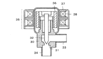
従来、空気調和機に使用される電動膨張弁としては、特開2006−258380号に記載されているようにステッピングモータの駆動により開度を調節する構成のものが知られている。具体的に、このような構成の電動膨張弁は、図12に示すように、弁本体30と、弁本体30の内部に形成されるリング状の弁座31と、弁座31の中心線に沿って配置される弁棒32とを備えている。
[Second Embodiment]
The invention according to the present embodiment relates to an air conditioner capable of reheat dehumidification.
2. Description of the Related Art Conventionally, as an electric expansion valve used in an air conditioner, there is known a configuration that adjusts an opening degree by driving a stepping motor as described in JP-A-2006-258380. Specifically, as shown in FIG. 12, the electric expansion valve having such a configuration includes a valve
弁棒(弁体)32の下端は円錐状に形成されており、弁棒32は、弁座31に対して近づき、または、離れる方向、すなわち、図中、上下方向に移動可能に設けられている。弁本体30の横側開口部には入口側配管33が接合され、弁本体30の下側開口部には出口側配管34が接合されている。また、弁本体30の上部には、弁棒32を上下動させるためのステッピングモータ35が設けられている。ステッピングモータ35のロータ36は弁棒32の上端部に結合されている。弁本体30の上部外周部にはネジ溝が形成されており、ロータ36の内周部はそのネジ溝に螺合されている。
The lower end of the valve stem (valve element) 32 is formed in a conical shape, and the
ステッピングモータ35のステータ37の電磁コイル38に正パルスを与えると、ロータ36が正方向に所定角度だけ回転して弁棒32が所定距離だけ弁座31に近づく。電磁コイル38に負パルスを与えるとロータ36が負方向に所定角度だけ回転して弁棒32が所定距離だけ弁座31から離れる。弁棒32を上下動させることにより、弁棒32の先端部と弁座31の隙間面積を変化させて、そこを通過する冷媒の流量を調節することができる。冷媒は入口側配管33から弁座31と弁棒32の隙間を介して出口側配管34に流れる。
When a positive pulse is applied to the
しかしながら、図12に記載された電磁弁においては、ステッピングモータのような高価な部品を用いているため、膨張弁も高価になるという問題点があった。そこで、本実施形態では、ステッピングモータを用いた電動膨張弁の代わりに安価な部品を使用しつつ、利便性の低下を抑制可能な空気調和機の提供を目的としている。 However, the solenoid valve described in FIG. 12 has a problem in that an expensive part such as a stepping motor is used, so that the expansion valve is also expensive. Therefore, the present embodiment aims to provide an air conditioner that can suppress a decrease in convenience while using inexpensive parts instead of an electric expansion valve using a stepping motor.
上記目的を達成するため、本発明者が検討した結果、冷媒回路に組込まれる膨張弁の中でも、室内熱交換器の間に介装され、再熱除湿運転時に膨張弁として機能する膨張弁は、空気中の水分を凝縮させることを目的とするため、除湿運転中に弁の開度を調整する必要性が低く、電動膨張弁の代わりに直動式電磁弁を利用した絞り機構に代替可能であるとともに、除湿運転終了後に、差圧を低減する制御を行なうことで利便性を低下させることなくスムーズに冷房運転を行なうことができることを見出した。 In order to achieve the above object, as a result of investigation by the present inventors, among the expansion valves incorporated in the refrigerant circuit, an expansion valve that is interposed between indoor heat exchangers and functions as an expansion valve during reheat dehumidification operation, The purpose is to condense the moisture in the air, so there is little need to adjust the valve opening during the dehumidification operation, and it can be replaced with a throttle mechanism that uses a direct acting solenoid valve instead of an electric expansion valve. In addition, it has been found that after the dehumidifying operation is completed, the cooling operation can be smoothly performed without reducing the convenience by performing the control for reducing the differential pressure.
すなわち、本発明は、圧縮機、室内熱交換器、絞り装置および室外熱交換器を含む冷媒回路と、前記室内熱交換器及び室内ファンを収容する室内機とを備え、前記室内熱交換器は、絞り機構を介して第1熱交換器及び第2熱交換器が直列的に接続され、前記第1熱交換器が凝縮器として機能し、前記第2熱交換器が蒸発器として機能する再熱除湿運転が可能な空気調和機であって、前記絞り機構が、電磁弁を利用したものであり、再熱除湿運転終了時に、前記絞り機構の上流側冷媒圧力と下流側冷媒圧力との差圧を低減する制御を行なうことを特徴とする。 That is, the present invention includes a refrigerant circuit including a compressor, an indoor heat exchanger, an expansion device, and an outdoor heat exchanger, and an indoor unit that houses the indoor heat exchanger and an indoor fan, and the indoor heat exchanger includes: The first heat exchanger and the second heat exchanger are connected in series via a throttle mechanism, the first heat exchanger functions as a condenser, and the second heat exchanger functions as an evaporator. An air conditioner capable of thermal dehumidification operation, wherein the throttle mechanism uses a solenoid valve, and when the reheat dehumidification operation ends, the difference between the upstream refrigerant pressure and the downstream refrigerant pressure of the throttle mechanism Control is performed to reduce the pressure.
ここで、絞り機構が電磁弁を利用するとは、基本的構造は直動式電磁弁と同じ構造としつつ、一部の構造を変更したものを絞り機構として用いたり、絞り機構の一部に直動式電磁弁を用いることを意味する。 Here, when the throttle mechanism uses a solenoid valve, the basic structure is the same as that of a direct acting solenoid valve, but a part of the structure is used as a throttle mechanism, or a part of the throttle mechanism is used directly. This means using a dynamic solenoid valve.
具体的には、直動式電磁弁を一部変更し、閉状態で絞り機能を有する冷媒の流通路が形成される構成としたものを絞り機構として使用することができる。そのほかにも、第1熱交換器及び第2熱交換器の間に、キャビラリチューブと、直動式電磁弁とを並列配置したものを絞り機構として使用することも可能である。 Specifically, it is possible to use, as a throttling mechanism, a structure in which a part of the direct acting solenoid valve is changed and a refrigerant flow passage having a throttling function is formed in a closed state. In addition, it is also possible to use, as a throttling mechanism, a cavity tube and a direct acting solenoid valve arranged in parallel between the first heat exchanger and the second heat exchanger.
上記構成によれば、再熱除湿運転時に膨張弁として機能する絞り機構が直動式電磁弁を利用したものであって安価である一方、再熱除湿運転終了後に、絞り機構の上流側冷媒圧力と下流側冷媒圧力との差圧を低減する制御を行なうことで、速やかに冷房運転に移行することが可能な、利便性の高い空気調和機を得ることができる。 According to the above configuration, the throttle mechanism that functions as an expansion valve during the reheat dehumidifying operation uses a direct acting solenoid valve, and is inexpensive. On the other hand, after completion of the reheat dehumidifying operation, the upstream side refrigerant pressure of the throttle mechanism By performing control to reduce the differential pressure between the refrigerant pressure and the downstream refrigerant pressure, it is possible to obtain a highly convenient air conditioner that can quickly shift to the cooling operation.
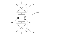
図13及び図14は、本発明の第2実施形態を示す図であり、図13は本実施形態の冷媒回路図を、図14は絞り機構の別形態の概略図を、それぞれ示す。本実施形態の空気調和機は、1台の室外機1に1台の室内機2が接続されたシングル型空気調和機である。そして、室外機1に収容される圧縮機3、室外熱交換器4及び絞り装置5をこの順に冷媒配管で直列に接続している。
FIGS. 13 and 14 are views showing a second embodiment of the present invention, FIG. 13 is a refrigerant circuit diagram of the present embodiment, and FIG. 14 is a schematic view of another embodiment of the throttle mechanism. The air conditioner of this embodiment is a single-type air conditioner in which one
さらに、絞り装置5から二方弁6を介して、室内機2に収容される室内熱交換器7を配管接続し、室内熱交換器7から三方弁8を介して、再び室外の圧縮機3に配管接続して冷媒回路を構成している。室内機2内には室内機に空気を取り入れて室内熱交換器7を通過させた後、機外に送出する室内ファン22が設置される。なお、絞り装置5は、絞り作用の無い全開状態にすることが可能な電動膨張弁からなる。
Furthermore, the
圧縮機3は、切換弁である四方弁9を介して冷媒回路に接続されており、四方弁9を切り換えることにより、室外熱交換器4側、又は、室内熱交換器7側のいずれの方向へも圧縮した冷媒を送出可能な構成とされている。この四方弁9の切り換えにより、室外熱交換器4と室内熱交換器7とが、凝縮器又は蒸発器として使用される。
The compressor 3 is connected to the refrigerant circuit via a four-
室内熱交換器7は、絞り機構23を介して第1熱交換器7a及び第2熱交換器7bが直列的に接続された構成とされる。本実施形態では絞り機構23として、閉状態で絞り機能を有する冷媒の流通路が形成される直動式電磁弁が用いられている。絞り機構23として使用される直動式電磁弁は、図12に示す電動膨張弁のステッピングモータの代りに、弁棒を上下動させるためにソレノイド及びコイル等の弾性体が使用される。
The
具体的には、ソレノイドへの通電時に、弾性体に抗して弁棒が弁座に近づくように下向きに移動して閉状態となり、通電停止とともに弾性体の復元力によって弁棒は上向きに移動して元の位置に戻って開状態となる構成とされる。そして、弁棒の先端部分であって弁座に接触する弁体に、切込み、突起部、貫通孔等を設けることで、閉状態で絞り機能を有する冷媒の流通路が形成される構成とされる。 Specifically, when the solenoid is energized, it moves downward so that the valve stem approaches the valve seat against the elastic body and closes, and when the energization stops, the valve stem moves upward by the restoring force of the elastic body And it is set as the structure which will return to the original position and will be in an open state. The valve body, which is the tip of the valve stem and is in contact with the valve seat, is provided with a notch, a protrusion, a through hole, etc., so that a refrigerant flow passage having a throttling function is formed in the closed state. The
上記構成において、冷房運転時及び暖房運転時には直動式電磁弁は全開とされ、第1熱交換器7aと第2熱交換器7bとの間に圧力差は生じず、両者を合わせて一つの熱交換器として機能する。具体的に、図13では、圧縮機3から吐出される冷媒が、図示する破線矢印方向に流通され、凝縮器としての室内熱交換器7、絞り装置5を経て蒸発器としての室外熱交換器4に流入されることによって暖房運転が実現される。
In the above configuration, the direct acting solenoid valve is fully opened during the cooling operation and the heating operation, and no pressure difference is generated between the
また、圧縮機3から吐出される高温の冷媒が、図示する実線矢印方向に流通され、凝縮器としての室外熱交換器4、絞り装置5を経て蒸発器としての室内熱交換器7に流入されることによって冷房運転が実現される。再熱除湿運転時には、冷媒は、冷房運転と同じく実線矢印方向に流通する。しかし、冷房運転時と異なり、絞り装置5は全開とされ、絞り機構23は電磁弁が閉状態とされ、冷媒流通路が形成されて膨張弁としての機能を発揮する。
Further, the high-temperature refrigerant discharged from the compressor 3 is circulated in the direction of the solid arrow shown in the figure, and flows into the
これにより、第1熱交換器7aは凝縮器として機能し、第2熱交換器7bは蒸発器として機能することで、第2熱交換器7bの表面において空気中の水分が凝縮し、室内熱交換器7全体として再熱除湿が行なわれる。なお、冷媒流通路の大きさは、最も絞り作用を発揮する大きさとされる。
Thereby, the
絞り機構23の別の形態としては、図14に示すように、第1熱交換器7a及び第2熱交換器7bの間に、キャビラリチューブ24と、直動式電磁弁25とを並列配置した構成とすることができる。すなわち、再熱除湿運転時には、絞り機構23の直動式電磁弁25は全閉状態とされ、冷媒はキャピラリチューブ24を通過することで膨張弁としての機能を発揮する。一方、冷房運転時及び暖房運転時には直動式電磁弁25は全開とされ、第1熱交換器7aと第2熱交換器7bを合わせて一つの熱交換器として機能する。
As another form of the
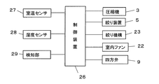
図15に示すように、空気調和機は、冷凍回路の運転を制御して、冷房運転、暖房運転及び再熱除湿運転等の空調運転を制御する制御装置26を備えている。空気調和機には、室内温度を検出する室温センサ27、室内湿度を検出する湿度センサ28、絞り機構23直動式電磁弁の弁棒が「開」位置にあることを検知する検知部29が設けられる。検知部29としては、例えば、弁棒が開位置に戻ったときに弁棒に接触して検知信号を出力するリミットスイッチを用いることができる。
As shown in FIG. 15, the air conditioner includes a
制御装置26は、CPU、メモリ等を備えたマイコンから構成され、空調運転の運転モードに応じて、これらの温度センサ・湿度センサの出力や、リモコン、本体の操作スイッチの操作信号等に基づき、圧縮機3、室内ファン22、絞り装置5、絞り機構23、四方弁9の動作等を制御して、冷媒回路の運転を制御する。
The
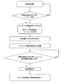
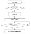
図16は、本実施形態における制御の一例を示すフローチャート図である。制御装置26は、再熱除湿運転終了時に、暖房運転を開始する。ここで、「再熱除湿運転終了時に」とは、本来的に、再熱除湿運転中に、リモコンや本体の操作スイッチの操作信号により、除湿運転から冷房運転への運転切替えの指令を受けたときを意味するが、再熱除湿運転の停止ボタンを押した後、冷房運転の開始ボタンを操作する場合も考えられることから、制御装置26が再熱除湿運転の停止指令を受けただけの場合であっても、「再熱除湿運転終了時に」と判断して差圧低減の制御を行なっておいてもよい。
FIG. 16 is a flowchart showing an example of control in the present embodiment. The
具体的には、圧縮機3の回転数を低下又は停止させた上で、四方弁9によって冷媒の流れる方向を暖房運転側に切替える。なお、このとき、短時間に暖房運転を完了させるために、室内ファン22を停止しておくのが好ましく、さらに加えて、室内機の空気吹出口に設置されるルーバパネルを閉じた状態にしておくのがより好ましい。
Specifically, after the rotational speed of the compressor 3 is reduced or stopped, the four-
次に、圧縮機3の回転数を通常の暖房運転時の回転数に設定する。このように、再熱除湿運転時とは逆向きに冷媒が流通することで、再熱除湿運転時に絞り機構23の上流側と下流側との間に生じていた差圧は低減され、電動式電磁弁の弁棒は弾性体の復元力によって、あるいは、弾性体の復元力に加えて弁棒に冷媒の逆圧がかかることにより、弁棒は早期に「開」位置に復帰する。
Next, the rotation speed of the compressor 3 is set to the rotation speed during normal heating operation. As described above, the refrigerant flows in the opposite direction to that during the reheat dehumidifying operation, so that the differential pressure generated between the upstream side and the downstream side of the
その結果、検知部29から検知信号が出力される。また、第1熱交換器7a及び第2熱交換器7bともに凝縮器として機能するため、室内熱交換器7の周辺温度が高くなる。室温センサ27は、通常、室内機の空気吸込口と室内熱交換器7との間に設置される。したがって、暖房運転として通常どおりルーバパネルを開放して、室内ファン22を運転した場合でも、ルーバパネルを閉鎖して室内ファン22を停止した状態にした場合のどちらであっても、直動式電磁弁が開状態に復帰することで室温センサ27の温度が上昇する。
As a result, a detection signal is output from the
制御装置26は、検知部29の検知信号を受けるか、室温センサ27における温度が上昇するかいずれかを検知することで直動式電磁弁(弁棒)が開状態に復帰したと判断して暖房運転を終了して再熱除湿運転が終了する。
The
これにより、再熱除湿運転の途中で冷房運転に切り替えても、速やかに再熱除湿運転を完了させて、冷房運転を行なうことが可能となり、電動膨張弁を使用した場合と同程度の利便性を維持することが可能となる。 As a result, even if switching to cooling operation during reheat dehumidification operation, it is possible to quickly complete reheat dehumidification operation and perform cooling operation, which is as convenient as using an electric expansion valve. Can be maintained.
また、差圧を低減する別の制御として、図17に示すように、再熱除湿運転終了時に、制御装置26は、圧縮機3を停止した状態で、絞り機構23の直動式電磁弁が開状態であるか、又は、所定時間が経過したことを検知するまで室内ファン22を運転させるようにすることも可能である。この場合、室内ファン22を運転させる時間は予め実験によって決定しておけばよい。また、このとき、室内ファンの回転数は、再熱除湿時よりも早い回転数としてもよい。このようにすることで、早く圧力差が解消する。
As another control for reducing the differential pressure, as shown in FIG. 17, at the end of the reheat dehumidifying operation, the
以上の実施形態の説明から明らかな通り、本実施形態の空気調和機は、圧縮機、室内熱交換器、絞り装置および室外熱交換器を含む冷媒回路と、前記室内熱交換器及び室内ファンを収容する室内機とを備え、前記室内熱交換器は、絞り機構を介して第1熱交換器及び第2熱交換器が直列的に接続され、前記第1熱交換器が凝縮器として機能し、前記第2熱交換器が蒸発器として機能する再熱除湿運転が可能な空気調和機であって、前記絞り機構が電磁弁を利用したものであり、再熱除湿運転終了時に、前記絞り機構の上流側冷媒圧力と下流側冷媒圧力との差圧を低減する制御を行なうことを特徴とする。 As is apparent from the above description of the embodiment, the air conditioner of the present embodiment includes a refrigerant circuit including a compressor, an indoor heat exchanger, an expansion device, and an outdoor heat exchanger, and the indoor heat exchanger and the indoor fan. The indoor heat exchanger includes a first heat exchanger and a second heat exchanger connected in series via a throttle mechanism, and the first heat exchanger functions as a condenser. An air conditioner capable of reheating and dehumidifying operation in which the second heat exchanger functions as an evaporator, wherein the throttling mechanism uses an electromagnetic valve, and when the reheating and dehumidifying operation ends, the throttling mechanism The control is performed to reduce the differential pressure between the upstream refrigerant pressure and the downstream refrigerant pressure.
前記絞り機構は、閉状態で絞り機能を有する冷媒の流通路が形成される構成とすることができる。また、絞り機構として、前記第1熱交換器及び第2熱交換器の間に、キャビラリチューブと、直動式電磁弁とを並列配置した構成とすることも可能である。 The throttle mechanism can be configured to form a refrigerant flow passage having a throttle function in a closed state. In addition, the throttle mechanism may be configured such that a cavity tube and a direct acting solenoid valve are arranged in parallel between the first heat exchanger and the second heat exchanger.
また、上記構成に加えて、空調運転を制御する制御装置を備え、制御装置は、前記差圧を低減する制御として、再熱除湿運転終了時に、前記直動式電磁弁が開状態であるか、又は、室内温度が上昇したことを検知するまで暖房運転を行なうことができる。なお、制御装置は、前記暖房運転の間、前記室内ファンを停止させるのが好ましい。 Further, in addition to the above configuration, a control device for controlling the air conditioning operation is provided, and the control device controls whether the direct acting solenoid valve is open at the end of the reheat dehumidifying operation as a control for reducing the differential pressure. Alternatively, the heating operation can be performed until it is detected that the room temperature has increased. In addition, it is preferable that a control apparatus stops the said indoor fan during the said heating operation.
上記制御の代わりに、前記制御装置は、前記差圧を低減する制御として、再熱除湿運転終了時に、圧縮機を停止した状態で、前記直動式電磁弁が開状態であるか、又は、所定時間が経過したことを検知するまで前記室内ファンを運転させることようにしてもよい。 Instead of the control, the control device, as a control to reduce the differential pressure, at the end of the reheat dehumidification operation, the compressor is stopped, the direct acting solenoid valve is open, or You may make it drive the said indoor fan until it detects that predetermined time passed.
本発明は、上記実施形態に限定されるものではなく、本発明の範囲内で上記実施形態に多くの修正および変更を加えることができる。具体的に、第1実施形態において、過冷却領域は、室外熱交換器の一部に形成された形態としたが、これに限らず、第3実施形態として、室外熱交換器と別体の過冷却器としてもよい。この場合、室外熱交換器及び過冷却器を合せて一つの室外熱交換器とみなすことができる。
また、第1実施形態における連結管14の管径は、配管12と同径であってもよいし、細径でも太径であってもよい。太径とする場合、振動に対して強くなるが、折り曲げが難しくなり、レシーバ設置の自由度が低くなる。一方、細径とすると、振動に対して弱くなるが、折り曲げがしやすく、レシーバ設置の自由度が高くなる。したがって、連結管14の管径は、実験などにより適切なものを選択すればよい。
The present invention is not limited to the above embodiment, and many modifications and changes can be made to the above embodiment within the scope of the present invention. Specifically, in the first embodiment, the supercooling region is formed in a part of the outdoor heat exchanger. However, the present invention is not limited to this, and the third embodiment is a separate body from the outdoor heat exchanger. A supercooler may be used. In this case, the outdoor heat exchanger and the subcooler can be regarded as one outdoor heat exchanger.
Further, the pipe diameter of the connecting
1 室外機
2 室内機
3 圧縮機
4 室外熱交換器
5 絞り装置
6 二方弁
7 室内熱交換器
8 三方弁
9 四方弁
11 配管
12 配管
12a 支管
12b バイパス管
13 レシーバ
14 連結管
15 出入口
16 ろう材
17 室外ファン
18 底板
19 凹部
20 排水口
21 飛散防止壁
22 室内ファン
23 絞り機構
24 キャピラリチューブ
25 直動式電磁弁
26 制御装置
27 室温センサ
28 湿度センサ
29 検知部
DESCRIPTION OF
Claims (13)
Priority Applications (2)
| Application Number | Priority Date | Filing Date | Title |
|---|---|---|---|
| JP2013254998A JP2015114010A (en) | 2013-12-10 | 2013-12-10 | Air conditioner |
| PCT/JP2014/070995 WO2015087579A1 (en) | 2013-12-10 | 2014-08-08 | Air conditioner |
Applications Claiming Priority (1)
| Application Number | Priority Date | Filing Date | Title |
|---|---|---|---|
| JP2013254998A JP2015114010A (en) | 2013-12-10 | 2013-12-10 | Air conditioner |
Publications (1)
| Publication Number | Publication Date |
|---|---|
| JP2015114010A true JP2015114010A (en) | 2015-06-22 |
Family
ID=53370898
Family Applications (1)
| Application Number | Title | Priority Date | Filing Date |
|---|---|---|---|
| JP2013254998A Pending JP2015114010A (en) | 2013-12-10 | 2013-12-10 | Air conditioner |
Country Status (2)
| Country | Link |
|---|---|
| JP (1) | JP2015114010A (en) |
| WO (1) | WO2015087579A1 (en) |
Cited By (1)
| Publication number | Priority date | Publication date | Assignee | Title |
|---|---|---|---|---|
| JP2023049799A (en) * | 2021-09-29 | 2023-04-10 | ダイキン工業株式会社 | Air conditioning system |
Family Cites Families (10)
| Publication number | Priority date | Publication date | Assignee | Title |
|---|---|---|---|---|
| JPS55146970U (en) * | 1979-04-11 | 1980-10-22 | ||
| JPS56142355A (en) * | 1980-04-02 | 1981-11-06 | Mitsubishi Heavy Ind Ltd | Air conditioner |
| JPH0434341Y2 (en) * | 1987-08-12 | 1992-08-17 | ||
| JP3013492B2 (en) * | 1990-10-04 | 2000-02-28 | 株式会社デンソー | Refrigeration apparatus, heat exchanger with modulator, and modulator for refrigeration apparatus |
| JP3455587B2 (en) * | 1994-06-29 | 2003-10-14 | 東芝キヤリア株式会社 | Air conditioner |
| JPH09210409A (en) * | 1996-01-30 | 1997-08-12 | Mitsubishi Heavy Ind Ltd | Outdoor unit for air conditioner |
| JPH1163632A (en) * | 1997-08-28 | 1999-03-05 | Hitachi Ltd | Air conditioner |
| JPH11281096A (en) * | 1998-03-31 | 1999-10-15 | Sanyo Electric Co Ltd | Outdoor unit for air conditioner |
| JP4548979B2 (en) * | 2001-06-27 | 2010-09-22 | 東芝キヤリア株式会社 | Air conditioner |
| JP2006177599A (en) * | 2004-12-22 | 2006-07-06 | Hitachi Home & Life Solutions Inc | Air conditioner |
-
2013
- 2013-12-10 JP JP2013254998A patent/JP2015114010A/en active Pending
-
2014
- 2014-08-08 WO PCT/JP2014/070995 patent/WO2015087579A1/en not_active Ceased
Cited By (2)
| Publication number | Priority date | Publication date | Assignee | Title |
|---|---|---|---|---|
| JP2023049799A (en) * | 2021-09-29 | 2023-04-10 | ダイキン工業株式会社 | Air conditioning system |
| JP7545057B2 (en) | 2021-09-29 | 2024-09-04 | ダイキン工業株式会社 | Air Conditioning Equipment |
Also Published As
| Publication number | Publication date |
|---|---|
| WO2015087579A1 (en) | 2015-06-18 |
Similar Documents
| Publication | Publication Date | Title |
|---|---|---|
| EP2631563A1 (en) | Air conditioner and control method thereof | |
| JP2014119145A (en) | Air conditioner | |
| EP2835589A2 (en) | Air conditioner | |
| KR20170038343A (en) | Air conditioner and a method controlling the same | |
| CN105910354B (en) | Air conditioner | |
| JP2013104623A (en) | Refrigeration cycle device and air conditioner with the same | |
| JP2006300370A (en) | Air conditioner | |
| JP2008082589A (en) | Air conditioner | |
| JP5071100B2 (en) | Air conditioner | |
| JP2018031527A (en) | Air conditioning device | |
| JP2018204814A (en) | Control apparatus, multiple type air conditioning system with the same, and control method and control program | |
| KR101414860B1 (en) | Air conditioner and method of controlling the same | |
| JP2015114010A (en) | Air conditioner | |
| JP3941817B2 (en) | Air conditioner | |
| JP2006300374A (en) | Air conditioner | |
| JP2014119154A (en) | Air conditioner | |
| JP2009192096A (en) | Air conditioner | |
| JP2014119146A (en) | Air conditioner | |
| JP2007032857A (en) | Refrigeration equipment | |
| JP5028927B2 (en) | Air conditioner | |
| JP5973336B2 (en) | Air conditioner | |
| JP2010127602A (en) | Refrigerating device | |
| JP3619533B2 (en) | Refrigeration equipment | |
| JP4981411B2 (en) | Air conditioner | |
| JPH06213531A (en) | Heat pump air conditioner for car |