JP2015100531A - Game machine - Google Patents

Game machine Download PDF

Info

Publication number
JP2015100531A
JP2015100531A JP2013243257A JP2013243257A JP2015100531A JP 2015100531 A JP2015100531 A JP 2015100531A JP 2013243257 A JP2013243257 A JP 2013243257A JP 2013243257 A JP2013243257 A JP 2013243257A JP 2015100531 A JP2015100531 A JP 2015100531A
Authority
JP
Japan
Prior art keywords
movable body
movable
state
player
character
Prior art date
Legal status (The legal status is an assumption and is not a legal conclusion. Google has not performed a legal analysis and makes no representation as to the accuracy of the status listed.)
Withdrawn
Application number
JP2013243257A
Other languages
Japanese (ja)
Inventor
孝弘 佐藤
Takahiro Sato
孝弘 佐藤
Current Assignee (The listed assignees may be inaccurate. Google has not performed a legal analysis and makes no representation or warranty as to the accuracy of the list.)
Okumura Yu Ki Co Ltd
Original Assignee
Okumura Yu Ki Co Ltd
Priority date (The priority date is an assumption and is not a legal conclusion. Google has not performed a legal analysis and makes no representation as to the accuracy of the date listed.)
Filing date
Publication date
Application filed by Okumura Yu Ki Co Ltd filed Critical Okumura Yu Ki Co Ltd
Priority to JP2013243257A priority Critical patent/JP2015100531A/en
Publication of JP2015100531A publication Critical patent/JP2015100531A/en
Withdrawn legal-status Critical Current

Links

Images

Landscapes

  • Pinball Game Machines (AREA)

Abstract

PROBLEM TO BE SOLVED: To provide a game machine which can execute performance using a movable accessory without affecting freshness even when a player continues playing.SOLUTION: A game machine includes a first movable body 45 to a fourth movable body 75 which are rotatably composed around a first rotary shaft 44 to a fourth rotary shaft 74 that have axial directions in the direction of a player. The game machine is provided with a movable accessory 30 where the first movable body 45 to the fourth movable body 75 gather to form an annular body and a part of outer periphery sides of the first movable body 45 to the fourth movable body 75 forms inner peripheral sides of the annular body. In the game machine, the first movable body 45 to the fourth movable body 75 are stopped at a prescribed angle around the first rotary shaft 44 to the fourth rotary shaft 74, so that an outline of a heart mark to be one character is expressed in a shape of the inner peripheral side of the annular body, and the first movable body 45 to fourth movable body 75 are stopped at another angle, so that an outline of a club mark to be another character is expressed in the shape of the inner peripheral side of the annular body.

Description

本発明は、遊技機の技術に関し、具体的には遊技機における可動役物に関する。   The present invention relates to gaming machine technology, and more specifically to a movable accessory in a gaming machine.

従来、パチンコ遊技機等の遊技機の多くに演出用の可動役物が搭載され、この可動役物によってキャラクタを表現する技術が用いられている(例えば、特許文献1を参照)。   2. Description of the Related Art Conventionally, a moving movable object for performance is mounted on many gaming machines such as pachinko gaming machines, and a technique for expressing a character by using this movable movable object has been used (see, for example, Patent Document 1).

特開2012−139600号公報JP 2012-139600 A

前記特許文献1に記載の技術の如く、従来技術に係る遊技機においては一つの可動役物で一つのキャラクタを表現している。このため、遊技者が遊技を継続するに従って新鮮味が損なわれていく。このため、遊技者が遊技を継続しても新鮮味が損なわれることがない、従来にない発想の可動役物による演出方法が求められていた。   Like the technique described in Patent Document 1, in a gaming machine according to the prior art, one character is represented by one movable accessory. For this reason, freshness is spoiled as a player continues a game. For this reason, there has been a demand for a production method using an unprecedented concept of a movable accessory that does not impair the fresh taste even if the player continues the game.

本発明は、上記のような問題点に鑑みてなされたものであり、遊技者が遊技を継続しても新鮮味を損なわずに可動役物を用いた演出を行うことが可能となる、遊技機を提供するものである。   The present invention has been made in view of the above problems, and a gaming machine capable of performing an effect using a movable accessory without losing the fresh taste even if the player continues the game. Is to provide.

本発明の解決しようとする課題は以上の如くであり、次にこの課題を解決するための手段を説明する。   The problem to be solved by the present invention is as described above. Next, means for solving the problem will be described.

即ち、請求項1においては、遊技者の方向に軸線方向を有する回転軸を中心として回転可能に構成された可動体を複数個備え、前記可動体が複数個集まって環状体が形成されるとともに、前記可動体の外周辺の一部によって前記環状体の内周辺が形成される可動役物を備える遊技機において、それぞれの前記可動体が前記回転軸を中心とする所定の角度で停止されることにより、前記環状体の内周辺の形状で一のキャラクタの外形線が表現されるとともに、一個以上の前記可動体が前記回転軸を中心とする他の角度で停止されることにより、前記環状体の内周辺の形状で一個以上の他のキャラクタの外形線が表現されるものである。   That is, in claim 1, a plurality of movable bodies configured to be rotatable around a rotation axis having an axial direction in a player's direction are provided, and a plurality of the movable bodies are gathered to form an annular body. In a gaming machine including a movable accessory in which an inner periphery of the annular body is formed by a part of an outer periphery of the movable body, each of the movable bodies is stopped at a predetermined angle around the rotation axis. Thus, the outline of one character is represented by the shape of the inner periphery of the annular body, and one or more of the movable bodies are stopped at other angles around the rotation axis, thereby The outline of one or more other characters is represented by the shape of the inner periphery of the body.

本発明により、遊技機において、遊技者が遊技を継続しても新鮮味を損なわずに可動役物を用いた演出を行うことが可能となる。   According to the present invention, in a gaming machine, it is possible to perform an effect using a movable accessory without losing freshness even if the player continues the game.

本発明の一実施形態に係るパチンコ遊技機の全体的な構成を示した正面図。The front view which showed the whole structure of the pachinko game machine which concerns on one Embodiment of this invention. 同じく、パチンコ遊技機の窓枠が開放された状態の構成を示した正面斜視図。Similarly, the front perspective view which showed the structure of the state by which the window frame of the pachinko game machine was open | released. 第一実施形態に係るパチンコ遊技機の遊技盤において通常状態の可動役物を示した正面図。The front view which showed the movable accessory of the normal state in the game board of the pachinko gaming machine concerning the first embodiment. 同じく第一状態の可動役物を示した正面図。The front view which similarly showed the movable accessory of the 1st state. 同じく第二状態の可動役物を示した正面図。The front view which showed the movable accessory of the 2nd state similarly. 第二実施形態に係るパチンコ遊技機の遊技盤において通常状態の可動役物を示した正面図。The front view which showed the movable accessory of the normal state in the game board of the pachinko machine which concerns on 2nd embodiment. 同じく第一状態の可動役物を示した正面図。The front view which similarly showed the movable accessory of the 1st state. 同じく第一状態の液晶画面の表示状態を示した正面図。The front view which similarly showed the display state of the liquid crystal screen of a 1st state. 同じく第二状態の可動役物を示した正面図。The front view which showed the movable accessory of the 2nd state similarly. 同じく第二状態の液晶画面の表示状態を示した正面図。The front view which similarly showed the display state of the liquid crystal screen of a 2nd state.

まず、本発明に係る遊技機の第一実施形態であるパチンコ遊技機の全体的な構成について、図面を用いて説明する。
なお、以下の説明では、パチンコ遊技機を遊技者側から見て、手前側をパチンコ遊技機の前側とし、奥側をパチンコ遊技機の後側として、前後方向を規定する。また、パチンコ遊技機を遊技者側から見て、左手側をパチンコ遊技機の左側とし、右手側をパチンコ遊技機の右側として、左右方向を規定する。
First, an overall configuration of a pachinko gaming machine that is a first embodiment of a gaming machine according to the present invention will be described with reference to the drawings.
In the following description, when the pachinko gaming machine is viewed from the player side, the front side is defined as the front side of the pachinko gaming machine and the back side is defined as the rear side of the pachinko gaming machine. Further, when the pachinko gaming machine is viewed from the player side, the left and right directions are defined with the left hand side as the left side of the pachinko gaming machine and the right hand side as the right side of the pachinko gaming machine.

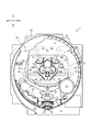
パチンコ遊技機は、図1及び図2が示すように、主として、外枠2と、中枠3と、窓枠4と、により構成される枠体に、各種の遊技部品が取り付けられて形成される。   As shown in FIGS. 1 and 2, the pachinko gaming machine is mainly formed by attaching various game parts to a frame constituted by an outer frame 2, an intermediate frame 3, and a window frame 4. The

外枠2は、パチンコ遊技機の外郭を成し、前後面が開口された略四角筒状に形成される枠体である。外枠2は、パチンコホール等の遊技場に設けられた台島に設置される。外枠2には、中枠3が設けられる。   The outer frame 2 is a frame body that forms the outline of a pachinko gaming machine and is formed in a substantially rectangular tube shape with front and rear surfaces opened. The outer frame 2 is installed in Taijima provided in a game hall such as a pachinko hall. The outer frame 2 is provided with an intermediate frame 3.

中枠3は、前後面が開口された略四角筒状に形成される枠体である。中枠3は、外枠2の前側の開口部にヒンジ等の軸支部材を介して回動可能に支持される。中枠3には、遊技盤5と、窓枠4と、下皿ユニット6と、が設けられる。   The middle frame 3 is a frame formed in a substantially rectangular tube shape with front and rear surfaces opened. The middle frame 3 is rotatably supported by a front opening of the outer frame 2 via a shaft support member such as a hinge. The middle frame 3 is provided with a game board 5, a window frame 4, and a lower tray unit 6.

遊技盤5は、略平板状に形成される部材である。遊技盤5は、中枠3の下側を除く略全面に渡って、中枠3に着脱自在に取り付けられる。遊技盤5の前側の表面には、遊技球が転動する領域である遊技領域19が形成される(図3から図5を参照)。また、遊技盤5における遊技領域19の部分には、遊技球を不規則に転動させるために図示しない多数の遊技釘が打ち込まれている。   The game board 5 is a member formed in a substantially flat plate shape. The game board 5 is detachably attached to the middle frame 3 over substantially the entire surface except the lower side of the middle frame 3. On the front surface of the game board 5, a game area 19 is formed, which is an area where the game ball rolls (see FIGS. 3 to 5). In addition, a large number of game nails (not shown) are driven into the game area 19 of the game board 5 in order to cause the game balls to roll irregularly.

窓枠4は、略平板状に形成される枠体である。窓枠4は、遊技盤5の前方に配置される。窓枠4は、中枠3の前側の開口部にヒンジ等の軸支部材を介して回動可能に支持される。窓枠4の略中央には、略円形状の窓枠開口部7が開口される。窓枠開口部7は、透明板27により被覆される。これによって、遊技者は、前方から透明板27を介して窓枠4の後方に配置された遊技盤5(より詳細には、遊技領域19)を視認することができる。窓枠開口部7の下方には、発射前の遊技球が貯溜される上皿8が配設される。窓枠開口部7の左右上方には、スピーカ9がそれぞれ配設される。   The window frame 4 is a frame formed in a substantially flat plate shape. The window frame 4 is disposed in front of the game board 5. The window frame 4 is rotatably supported by an opening on the front side of the middle frame 3 via a shaft support member such as a hinge. A substantially circular window frame opening 7 is opened at the approximate center of the window frame 4. The window frame opening 7 is covered with a transparent plate 27. Thereby, the player can visually recognize the game board 5 (more specifically, the game area 19) disposed behind the window frame 4 through the transparent plate 27 from the front. Below the window frame opening 7, an upper plate 8 for storing game balls before launching is disposed. Speakers 9 are disposed above and to the left and right of the window frame opening 7.

下皿ユニット6は、中枠3の下側であって窓枠4の下方に取り付けられる。下皿ユニット6の略中央には、上皿8から溢れた遊技球が貯溜される下皿25が配設される。下皿ユニット6の右側部であって下皿25の右方には、上皿8に貯溜された遊技球を遊技盤5の遊技領域19へ向けて発射可能に構成される発射ハンドル26が配設される。   The lower dish unit 6 is attached below the middle frame 3 and below the window frame 4. In the approximate center of the lower tray unit 6, a lower tray 25 in which game balls overflowing from the upper tray 8 are stored is disposed. On the right side of the lower tray unit 6 and to the right of the lower tray 25, a launching handle 26 configured to be able to launch the game balls stored in the upper tray 8 toward the game area 19 of the game board 5 is arranged. Established.

次に、遊技盤5の構成について、図3を用いてさらに詳細に説明する。   Next, the configuration of the game board 5 will be described in more detail with reference to FIG.

遊技盤5には、遊技部品としてガイドレール10、図柄表示装置11、図柄表示開口部12、一般入賞口13、大入賞装置14、可変入賞装置15、アウト口16、装飾板18、可動役物30などが設けられている。   The game board 5 includes a guide rail 10, a symbol display device 11, a symbol display opening portion 12, a general winning opening 13, a grand winning device 14, a variable winning device 15, an out port 16, a decorative plate 18, and a movable accessory as gaming parts. 30 etc. are provided.

ガイドレール10は、略円弧状に形成された帯状の部材である。ガイドレール10は、遊技盤5の前側面に、当該前側面に対して立ち上がり状に取り付けられる。ガイドレール10は、遊技盤5の前側面に正面視で略円形状を形成するように配置される。そして、遊技盤5において、ガイドレール10により略円形状に形成された内側の領域が、遊技球が転動する領域である遊技領域19として構成される。   The guide rail 10 is a belt-like member formed in a substantially arc shape. The guide rail 10 is attached to the front side surface of the game board 5 in a rising shape with respect to the front side surface. The guide rail 10 is disposed on the front side surface of the game board 5 so as to form a substantially circular shape when viewed from the front. And in the game board 5, the inner area | region formed in the substantially circular shape by the guide rail 10 is comprised as the game area | region 19 which is an area | region where a game ball rolls.

図柄表示装置11は、液晶画面20を設けて、当該液晶画面20に図柄や数字等を変動表示可能に構成される装置である。図柄表示装置11は、液晶画面20を前方へ向けた状態で、遊技盤5の後側面に取り付けられる。   The symbol display device 11 is a device that is provided with a liquid crystal screen 20 so that symbols, numbers, and the like can be variably displayed on the liquid crystal screen 20. The symbol display device 11 is attached to the rear side of the game board 5 with the liquid crystal screen 20 facing forward.

図柄表示開口部12は、遊技者が前方から図柄表示装置11の液晶画面20を視認するための開口部である。図柄表示開口部12は、正面視で遊技領域19の概ね中央で、遊技盤5を前後方向に貫通して形成される。図柄表示開口部12には、図柄表示装置11の液晶画面20が配置される。これによって、遊技者は、前方から図柄表示開口部12を通じて遊技盤5の後側面に取り付けられた図柄表示装置11の液晶画面20を視認することができる。   The symbol display opening 12 is an opening through which a player can visually recognize the liquid crystal screen 20 of the symbol display device 11 from the front. The symbol display opening 12 is formed substantially in the center of the game area 19 in front view and penetrates the game board 5 in the front-rear direction. A liquid crystal screen 20 of the symbol display device 11 is disposed in the symbol display opening 12. Thereby, the player can visually recognize the liquid crystal screen 20 of the symbol display device 11 attached to the rear side surface of the game board 5 through the symbol display opening 12 from the front.

一般入賞口13は、上面が開口されたポケット状に形成され、遊技球が入球(入賞)可能に形成される部材である。一般入賞口13は、遊技領域19の下部であって適宜な位置に複数個が配置される。一般入賞口13は、遊技球が入球すると図示せぬ賞球払出装置によって所定数の遊技球(賞球)が払い出されるように構成される。   The general winning opening 13 is a member that is formed in a pocket shape having an open upper surface so that a game ball can be entered (winning). A plurality of general winning openings 13 are arranged at appropriate positions below the game area 19. The general winning opening 13 is configured such that when a game ball enters, a predetermined number of game balls (prize balls) are paid out by a prize ball payout device (not shown).

大入賞装置14は、所定の大当たり抽選により大当たりが選択されると、大入賞口21を開放して遊技球が入球(入賞)可能に構成される装置である。大入賞装置14は、遊技領域19の中央下部に配置される。大入賞装置14は、開放した大入賞口21に遊技球が入球すると図示せぬ賞球払出装置によって所定数の遊技球(賞球)が払い出されるように構成される。   The big winning device 14 is a device configured to open the big winning opening 21 and to allow a game ball to enter (win) when a big win is selected by a predetermined big win lottery. The big winning device 14 is arranged at the lower center of the game area 19. The grand prize winning device 14 is configured such that when a game ball enters the opened big prize opening 21, a predetermined number of game balls (prize balls) are paid out by a prize ball payout device (not shown).

可変入賞装置15は、所定の作動条件に応じて左右一対の可動片22が開閉作動し、始動入賞口23に遊技球が入球(入賞)可能な開放状態と入球(入賞)不能な閉塞状態とに切り替え可能に構成される装置である。可変入賞装置15は、遊技領域19において図柄表示開口部12の下方であって大入賞装置14の上方に配置される。可変入賞装置15は、前記開放状態において始動入賞口23に遊技球が入球(入賞)すると図示せぬ賞球払出装置によって所定数の遊技球(賞球)が払い出されるように構成される。   In the variable winning device 15, the pair of left and right movable pieces 22 are opened and closed in accordance with predetermined operating conditions, and an open state in which a game ball can enter (win) and a block that cannot enter (win) can be entered. It is a device that can be switched to a state. The variable winning device 15 is arranged below the symbol display opening 12 and above the big winning device 14 in the game area 19. The variable winning device 15 is configured such that a predetermined number of game balls (prize balls) are paid out by a prize ball payout device (not shown) when a game ball enters (wins) the start winning port 23 in the open state.

アウト口16は、遊技領域19を転動する遊技球が、一般入賞口13や大入賞口21や始動入賞口23等の各入賞口に入球(入賞)しなかった場合に、最終的に流入する開口部である。アウト口16は、遊技領域19の最下部に、遊技盤5を前後方向に貫通して形成される。なお、アウト口16に流入した遊技球は、パチンコ遊技機が設置されたパチンコホール等の遊技場側に回収される。   When the game balls rolling in the game area 19 do not enter (win) the winning holes such as the general winning holes 13, the big winning holes 21, the starting winning holes 23, etc. It is an opening part which flows in. The out port 16 is formed at the lowermost part of the game area 19 so as to penetrate the game board 5 in the front-rear direction. Note that the game ball that has flowed into the out port 16 is collected at a game hall such as a pachinko hall in which a pachinko gaming machine is installed.

装飾板18は、後述する可動役物30や各種の発光部材等が配設される板状部材である。装飾板18に配設される可動役物30及び各種発光部材が、大当たり時やイベント開始時において駆動及び発光による演出を行う。これにより、パチンコ遊技機は遊技者に視覚的な印象(インパクト)を与え、遊技者の興趣を高めるように構成されている。   The decorative plate 18 is a plate-like member on which a movable accessory 30 described later, various light emitting members, and the like are disposed. The movable accessory 30 and various light emitting members disposed on the decorative plate 18 perform an effect by driving and light emission at the time of a big hit or at the start of an event. Thereby, the pachinko gaming machine is configured to give a visual impression (impact) to the player and enhance the interest of the player.

可動役物30は、図3に示す如く、図柄表示開口部12の上側端部及び左右両側端部において装飾板18に配設される。そして、図3から図5に示す如く、適宜図柄表示装置11における液晶画面20の前側で四個の可動体(第一可動体45・第二可動体55・第三可動体65・第四可動体75)を回転させつつ進退させるように駆動されて演出を行う。   As shown in FIG. 3, the movable accessory 30 is disposed on the decorative plate 18 at the upper end and the left and right ends of the symbol display opening 12. Then, as shown in FIGS. 3 to 5, four movable bodies (first movable body 45, second movable body 55, third movable body 65, fourth movable body) are appropriately disposed on the front side of the liquid crystal screen 20 in the symbol display device 11. The body 75) is driven to move forward and backward while rotating.

次に、本実施形態に係る可動役物30の構成について、図3から図5を用いてさらに詳細に説明する。
可動役物30は、四個の可動体(第一可動体45・第二可動体55・第三可動体65・第四可動体75)を備える。本実施形態においては、図3に示す如く第一可動体45〜第四可動体75が退避した状態を「通常状態」、図4に示す如く第一可動体45〜第四可動体75で一のキャラクタであるハートマークを形成する状態を「第一状態」、図5に示す如く第一可動体45〜第四可動体75で他のキャラクタであるクラブマークを形成する状態を「第二状態」として記載する。
Next, the configuration of the movable accessory 30 according to the present embodiment will be described in more detail with reference to FIGS.
The movable accessory 30 includes four movable bodies (a first movable body 45, a second movable body 55, a third movable body 65, and a fourth movable body 75). In the present embodiment, the state in which the first movable body 45 to the fourth movable body 75 are retracted as shown in FIG. 3 is the “normal state”, and the first movable body 45 to the fourth movable body 75 as shown in FIG. The state of forming the heart mark that is the character of the first character is the “first state”, and the state of forming the club mark that is the other character with the first movable body 45 to the fourth movable body 75 as shown in FIG. ".

第一可動体45は、遊技者の方向(前方)に軸線方向を有する第一回転軸44を中心として回転可能に構成される。具体的には図3に示す如く、装飾板18の背面(遊技者と反対側の面)における図柄表示開口部12の左側側端部には、ケースの内部に第一駆動モータが収容された第一駆動部41が固定されている。第一駆動モータは駆動軸42の軸線方向を上下に向けて配設され、その駆動軸42には第一ラック部材43が左右方向に移動可能に配設されている。詳細には、駆動軸42にはピニオンギヤが、第一ラック部材43にはラックギヤが形成され、互いに歯合されているのである。   The first movable body 45 is configured to be rotatable about a first rotation shaft 44 having an axial direction in the player's direction (front). Specifically, as shown in FIG. 3, the first drive motor is accommodated inside the case at the left side end of the symbol display opening 12 on the back surface (the surface opposite to the player) of the decorative board 18. The first drive unit 41 is fixed. The first drive motor is disposed with the axial direction of the drive shaft 42 facing up and down, and a first rack member 43 is disposed on the drive shaft 42 so as to be movable in the left-right direction. More specifically, a pinion gear is formed on the drive shaft 42 and a rack gear is formed on the first rack member 43, and they are engaged with each other.

第一ラック部材43の右端部には、前方である遊技者側に突出する第一回転軸44が配設されるとともに、第一可動体45が第一回転軸44を軸として回動自在に配設されている。具体的には、第一可動体45は、第一ラック部材43の右端部に固定された図示しない回動モータと連結されており、回動モータを駆動させることにより、第一回転軸44を軸として回動する。つまり、第一可動体45は回動モータの駆動により、第一回転軸44を軸として回動可能に構成されているのである。   At the right end of the first rack member 43, a first rotating shaft 44 that protrudes toward the player, which is the front, is disposed, and the first movable body 45 is rotatable about the first rotating shaft 44. It is arranged. Specifically, the first movable body 45 is connected to a rotation motor (not shown) fixed to the right end of the first rack member 43, and the first rotation shaft 44 is driven by driving the rotation motor. It rotates as an axis. That is, the first movable body 45 is configured to be rotatable about the first rotation shaft 44 by driving a rotation motor.

第二可動体55〜第四可動体75についても、第一可動体45と同様の構成により、遊技者の方向(前方)に軸線方向を有する第二回転軸54〜第四回転軸74を中心として回転可能に構成される。具体的には図3に示す如く、装飾板18の背面(遊技者と反対側の面)における図柄表示開口部12の上側端部の左側、上側端部の右側、及び、右側側端部のそれぞれには、ケースの内部に第二駆動モータ〜第四駆動モータが収容された第二駆動部51〜第四駆動部71が固定されている。第二駆動モータは駆動軸52の軸線方向を右上方向に向けて配設され、その駆動軸52には第二ラック部材53が右下方向及び左上方向に移動可能に配設されている。第三駆動モータは駆動軸62の軸線方向を左上方向に向けて配設され、その駆動軸62には第三ラック部材63が左下方向及び右上方向に移動可能に配設されている。第四駆動モータは駆動軸72の軸線方向を上下に向けて配設され、その駆動軸72には第四ラック部材73が左右方向に移動可能に配設されている。第二ラック部材53〜第四ラック部材73の先端部には、前方である遊技者側に突出する第二回転軸54〜第四回転軸74が配設されるとともに、第二可動体55〜第四可動体75が第二回転軸54〜第四回転軸74を軸として回動自在に配設されている。   The second movable body 55 to the fourth movable body 75 also have the same configuration as the first movable body 45, and the second rotational shaft 54 to the fourth rotational shaft 74 having an axial direction in the player's direction (front) are centered. Is configured to be rotatable. Specifically, as shown in FIG. 3, the left side of the upper end of the symbol display opening 12, the right side of the upper end, and the right side end of the rear surface of the decorative board 18 (the side opposite to the player). In each case, the second drive unit 51 to the fourth drive unit 71 in which the second drive motor to the fourth drive motor are housed are fixed inside the case. The second drive motor is disposed with the axial direction of the drive shaft 52 facing the upper right direction, and the second rack member 53 is disposed on the drive shaft 52 so as to be movable in the lower right direction and the upper left direction. The third drive motor is disposed with the axial direction of the drive shaft 62 facing the upper left direction, and a third rack member 63 is disposed on the drive shaft 62 so as to be movable in the lower left direction and the upper right direction. The fourth drive motor is disposed with the axial direction of the drive shaft 72 facing up and down, and a fourth rack member 73 is disposed on the drive shaft 72 so as to be movable in the left-right direction. At the front end of the second rack member 53 to the fourth rack member 73, a second rotating shaft 54 to a fourth rotating shaft 74 projecting to the player side which is the front are disposed, and the second movable body 55 to 55 are disposed. A fourth movable body 75 is rotatably disposed around the second rotation shaft 54 to the fourth rotation shaft 74.

第一可動体45〜第四可動体75は、回転した際に隣接する可動体同士が干渉しないように、前後位置をずらして配置されている。具体的には図3に示す如く、第一ラック部材43及び第三ラック部材63は駆動軸42及び駆動軸62よりも前側に配置され、第二ラック部材53及び第四ラック部材73は駆動軸52及び駆動軸72よりも後側に配置されている。これにより、第一可動体45及び第三可動体65は、第二可動体55及び第四可動体75よりも前側に配置されることになるため、回転した際に隣接する可動体同士で干渉することがないのである。   The first movable body 45 to the fourth movable body 75 are arranged with their front and rear positions shifted so that adjacent movable bodies do not interfere with each other when rotated. Specifically, as shown in FIG. 3, the first rack member 43 and the third rack member 63 are arranged in front of the drive shaft 42 and the drive shaft 62, and the second rack member 53 and the fourth rack member 73 are the drive shaft. 52 and the rear side of the drive shaft 72. Thereby, since the 1st movable body 45 and the 3rd movable body 65 will be arrange | positioned ahead of the 2nd movable body 55 and the 4th movable body 75, when it rotates, adjacent movable bodies will interfere. There is nothing to do.

可動役物30においては、図4に示す如く、第一可動体45〜第四可動体75が集まって環状体が形成される。そして、第一可動体45〜第四可動体75の外周辺の一部によって環状体の内周辺が形成される。具体的には、第一可動体45〜第四可動体75の外周辺の一部には、図3及び図4に示す如く第一辺部45a〜75aが形成されている。さらに、第一状態における可動役物30においては、第一可動体45〜第四可動体75が第一回転軸44〜第四回転軸74を中心とする所定の角度(第一辺部45a〜75aがひと続きの形状となる角度)で停止される。これにより図4に示す如く、第一辺部45a〜75aが集まって形成される環状体の内周辺の形状で、一のキャラクタであるハートマークの外形線が表現される。換言すれば、第一辺部45a〜75aはハートマークの外形線を四分割した形状に形成されているのである。なお、本実施形態における「キャラクタ」は、本実施形態に示す如く単なるマークを用いることも、人物や動物等の生物及びその一部、車や本などの無生物などの他の物体を用いることも可能である。   In the movable accessory 30, as shown in FIG. 4, the first movable body 45 to the fourth movable body 75 gather to form an annular body. The inner periphery of the annular body is formed by a part of the outer periphery of the first movable body 45 to the fourth movable body 75. Specifically, first side portions 45 a to 75 a are formed in a part of the outer periphery of the first movable body 45 to the fourth movable body 75 as shown in FIGS. 3 and 4. Further, in the movable combination 30 in the first state, the first movable body 45 to the fourth movable body 75 are at predetermined angles (first side portions 45a to 45a to 45a) around the first rotation shaft 44 to the fourth rotation shaft 74. 75a is stopped at an angle that forms a continuous shape). As a result, as shown in FIG. 4, the outline of the heart mark, which is one character, is expressed in the shape of the inner periphery of the annular body formed by gathering the first side portions 45a to 75a. In other words, the first side portions 45a to 75a are formed in a shape obtained by dividing the outline of the heart mark into four parts. The “character” in the present embodiment may be a simple mark as shown in the present embodiment, or may be a living object such as a person or an animal or a part thereof, or another object such as an inanimate object such as a car or a book. Is possible.

また、第一可動体45〜第四可動体75の外周辺における第一辺部45a〜75aの反対側には、図3及び図5に示す如く第二辺部45b〜75bが形成されている。さらに、第二状態における可動役物30においては、第一可動体45〜第四可動体75が第一回転軸44〜第四回転軸74を中心とする他の角度(第二辺部45b〜75bがひと続きの形状となる角度)で停止される。これにより図5に示す如く、第二辺部45b〜75bが集まって形成される環状体の内周辺の形状で、他のキャラクタであるクラブマークの外形線が表現される。換言すれば、第二辺部45b〜75bはクラブマークの外形線を四分割した形状に形成されているのである。   Further, second side portions 45b to 75b are formed on the outer sides of the first movable body 45 to the fourth movable body 75 on the opposite side of the first side portions 45a to 75a as shown in FIGS. . Furthermore, in the movable combination 30 in the second state, the first movable body 45 to the fourth movable body 75 are at other angles (second side portions 45b to 45b) around the first rotation shaft 44 to the fourth rotation shaft 74. 75b is stopped at an angle that forms a continuous shape). As a result, as shown in FIG. 5, the outline of the club mark, which is another character, is expressed in the shape of the inner periphery of the annular body formed by gathering the second sides 45b to 75b. In other words, the second sides 45b to 75b are formed in a shape obtained by dividing the outline of the club mark into four parts.

本実施形態に係る遊技機においては上記の如く構成することにより、遊技者が遊技を継続しても新鮮味を損なわずに可動役物30を用いた演出を行うことが可能となる。具体的には、一つの可動役物30で、何も表現していない状態(本実施形態における通常状態)から、複数のキャラクタ(本実施形態においては第一状態のハートマークと第二状態のクラブマーク)を表現することができるため、遊技者に対して次に何のキャラクタが表現されるのかという興味を起こさせることができる。つまり、可動役物30を用いて、遊技者に対して様々なキャラクタを表現することができるため、遊技者に驚きや意外性を感じさせることのできる、従来にない演出を行うことが可能となるのである。   In the gaming machine according to the present embodiment, by configuring as described above, it is possible to perform an effect using the movable accessory 30 without losing freshness even if the player continues the game. Specifically, from a state where nothing is expressed by one movable accessory 30 (normal state in the present embodiment), a plurality of characters (in this embodiment, a heart symbol in the first state and a second state in the second state). The club mark) can be expressed, so that the player can be interested in what character will be expressed next. In other words, since various characters can be expressed to the player using the movable accessory 30, it is possible to perform an unprecedented effect that can make the player feel surprised or unexpected. It becomes.

なお、本実施形態においては、四個の可動体(第一可動体45〜第四可動体75)で環状体を形成し、第一状態及び第二状態としたが、可動体の個数は限定されるものではない。即ち、二個、三個、又は五個以上の可動体で環状体を形成する構成としても差し支えない。   In this embodiment, an annular body is formed by four movable bodies (first movable body 45 to fourth movable body 75) to be in the first state and the second state, but the number of movable bodies is limited. Is not to be done. That is, a configuration in which an annular body is formed by two, three, or five or more movable bodies may be used.

また、本実施形態においては、第一可動体45〜第四可動体75で第一状態のハートマークと第二状態のクラブマークという二個のキャラクタを表現する構成としたが、キャラクタの個数は三個以上とする(第三状態以上のキャラクタを表現する)ことも可能である。即ち、複数個の可動体の全てを回転させずに、一個以上の一部の回転体を回転させることにより、別のキャラクタを表現する構成としても良い。また、本実施形態においては第一可動体45〜第四可動体75のそれぞれに第一辺部45a〜75aと第二辺部45b〜75bとを形成したが、可動体に他の辺部を形成し、それらを組み合わせることによって、表現するキャラクタの個数を増やすことも可能である。   In the present embodiment, the first movable body 45 to the fourth movable body 75 are configured to represent two characters, the first state heart mark and the second state club mark. It is also possible to use three or more (representing characters in the third state or more). In other words, another character may be expressed by rotating one or more partial rotating bodies without rotating all of the plurality of movable bodies. Moreover, in this embodiment, although the 1st edge part 45a-75a and the 2nd edge part 45b-75b were formed in each of the 1st movable body 45-the 4th movable body 75, another edge part is attached to a movable body. It is also possible to increase the number of characters to be expressed by forming them and combining them.

また、本実施形態における環状体は、第一可動体45〜第四可動体75によって、第一辺部45a〜75a又は第二辺部45b〜75bがひと続きの形状となる閉じた環を形成したが、環状体はキャラクタを表現できる程度に形成されていればよく、例えば隣接する可動体のうち数箇所がつながっておらず、一部に開放された部分(切欠き部分)を残した環状体であっても差し支えない。   Moreover, the annular body in this embodiment forms a closed ring in which the first side portions 45a to 75a or the second side portions 45b to 75b are formed in a continuous shape by the first movable body 45 to the fourth movable body 75. However, the ring body only needs to be formed to the extent that the character can be expressed. For example, some of the adjacent movable bodies are not connected, and the ring is left with a part opened (notch). It can be a body.

また、第一可動体45〜第四可動体75で環状体を形成し、キャラクタを表現した後に、第一可動体45〜第四可動体75を微妙に進退させたり、回転させたりすることにより、遊技者にキャラクタが少し動いているように見せることもできる。さらに、例えばパチンコ遊技機で大当りとなる際などに、第一可動体45〜第四可動体75が順に回転を止めていき、最後にキャラクタが完成する構成とすることにより、遊技者が感じる興趣性を高めることも可能である。   Further, by forming an annular body with the first movable body 45 to the fourth movable body 75 and expressing the character, the first movable body 45 to the fourth movable body 75 are slightly advanced / retracted or rotated. , It can also be shown to the player as if the character is moving a little. Further, for example, when a big hit is made with a pachinko gaming machine, the first movable body 45 to the fourth movable body 75 stop rotating in order, and finally the character is completed. It is also possible to increase the nature.

また、本実施形態においては、第一可動体45〜第四可動体75において、図4に示す如く第一辺部45a〜75aの近傍には丸型の第一突起部46a〜76aが形成されている。また、図5に示す如く第二辺部45b〜75bの近傍には四角型の第二突起部46b〜76bが形成されている。このように、一のキャラクタであるハートマークの外形線を表現する第一辺部45a〜75aと、他のキャラクタであるクラブマークの外形線を表現する第二辺部45b〜75bとに異なる突起部を形成することにより、遊技者が異なるキャラクタであるハートマークとクラブマークとを判別しやすくしている。なお、異なるキャラクタを表現する辺部に異なる彩色を施すことにより、それぞれのキャラクタを判別しやすくすることも可能である。例えば、本実施形態における第一辺部45a〜75aの周辺を赤く彩色し、第二辺部45b〜75bの周辺を青く彩色することにより、異なるキャラクタを判別しやすくすることもできる。   In the present embodiment, in the first movable body 45 to the fourth movable body 75, round first protrusions 46a to 76a are formed in the vicinity of the first sides 45a to 75a as shown in FIG. ing. Further, as shown in FIG. 5, square-shaped second protrusions 46b to 76b are formed in the vicinity of the second sides 45b to 75b. In this way, different protrusions are formed on the first sides 45a to 75a representing the outline of the heart mark that is one character and the second sides 45b to 75b representing the outline of the club mark that is another character. By forming the part, it is easy to distinguish the heart mark and the club mark, which are different characters by the player. In addition, it is also possible to make it easy to distinguish each character by giving different coloring to the sides representing different characters. For example, different characters can be easily distinguished by coloring the periphery of the first side portions 45a to 75a in the present embodiment in red and coloring the periphery of the second side portions 45b to 75b in blue.

次に、本発明に係る遊技機の第二実施形態であるパチンコ遊技機における可動役物130の構成について、図6から図10を用いて説明する。以下においては、第一実施形態と同様の構成については同符号を付してその説明を省略し、第一実施形態と異なる構成を中心に説明することとする。   Next, the configuration of the movable accessory 130 in the pachinko gaming machine that is the second embodiment of the gaming machine according to the present invention will be described with reference to FIGS. In the following description, the same components as those in the first embodiment are denoted by the same reference numerals, and the description thereof is omitted. The components different from those in the first embodiment will be mainly described.

可動役物130は、第一実施形態における可動役物30と同様に、四個の可動体(第一可動体145・第二可動体155・第三可動体165・第四可動体175)を備える。本実施形態においても、図6に示す如く第一可動体145〜第四可動体175が退避した状態を「通常状態」、図7に示す如く第一可動体145〜第四可動体175で一のキャラクタ(ジャンケンにおける「パー」)を形成する状態を「第一状態」、図9に示す如く第一可動体145〜第四可動体175で他のキャラクタ(ジャンケンにおける「チョキ」)を形成する状態を「第二状態」として記載する。   The movable combination 130 includes four movable bodies (first movable body 145, second movable body 155, third movable body 165, and fourth movable body 175), similar to the movable combination 30 in the first embodiment. Prepare. Also in this embodiment, the state in which the first movable body 145 to the fourth movable body 175 are retracted as shown in FIG. 6 is “normal state”, and the first movable body 145 to the fourth movable body 175 are one as shown in FIG. The state of forming the character ("par" in janken) is the "first state", and as shown in FIG. 9, the first movable body 145 to the fourth movable body 175 form another character ("joki" in janken) The state is described as “second state”.

第一可動体145〜第四可動体175は、第一実施形態と同様に、遊技者の方向(前方)に軸線方向を有する第一回転軸44〜第四回転軸74を中心として回転可能に構成される。そして、可動役物130においては、図7に示す如く、第一可動体145〜第四可動体175が集まって環状体が形成される。そして、第一可動体145〜第四可動体175の外周辺の一部によって環状体の内周辺が形成される。具体的には、第一可動体145〜第四可動体175の外周辺の一部には、図7に示す如く第一辺部145a〜175aが形成されている。さらに、第一状態における可動役物130においては、第一可動体145〜第四可動体175が第一回転軸44〜第四回転軸74を中心とする所定の角度(第一辺部145a〜175aがひと続きの形状となる角度)で停止される。これにより図7に示す如く、第一辺部145a〜175aが集まって形成される環状体の内周辺の形状で、一のキャラクタ(ジャンケンにおける「パー」)の外形線が表現される。換言すれば、第一辺部145a〜175aはジャンケンにおける「パー」の外形線を四分割した形状に形成されているのである。   As in the first embodiment, the first movable body 145 to the fourth movable body 175 are rotatable about a first rotation shaft 44 to a fourth rotation shaft 74 having an axial direction in the player's direction (front). Composed. And in the movable accessory 130, as shown in FIG. 7, the 1st movable body 145-the 4th movable body 175 gather, and an annular body is formed. The inner periphery of the annular body is formed by a part of the outer periphery of the first movable body 145 to the fourth movable body 175. Specifically, first side portions 145a to 175a are formed in a part of the outer periphery of the first movable body 145 to the fourth movable body 175 as shown in FIG. Further, in the movable combination 130 in the first state, the first movable body 145 to the fourth movable body 175 have predetermined angles (first side portions 145a to 145a to 145) centered on the first rotation shaft 44 to the fourth rotation shaft 74. 175a is stopped at an angle). As a result, as shown in FIG. 7, the outline of one character (“par” in janken) is expressed in the shape of the inner periphery of the annular body formed by gathering the first side portions 145a to 175a. In other words, the first side portions 145a to 175a are formed in a shape obtained by dividing the outline of “par” in janken into four parts.

また、第一可動体145〜第四可動体175の外周辺における第一辺部145a〜175aの反対側には、図9に示す如く第二辺部145b〜175bが形成されている。さらに、第二状態における可動役物130においては、第一可動体145〜第四可動体175が第一回転軸44〜第四回転軸74を中心とする他の角度(第二辺部145b〜175bがひと続きの形状となる角度)で停止される。これにより図9に示す如く、第二辺部145b〜175bが集まって形成される環状体の内周辺の形状で、他のキャラクタ(ジャンケンにおける「チョキ」)の外形線が表現される。換言すれば、第二辺部145b〜175bはジャンケンにおける「チョキ」の外形線を四分割した形状に形成されているのである。   In addition, second side portions 145b to 175b are formed on the opposite side of the first movable body 145 to the fourth movable body 175 on the opposite side of the first side portions 145a to 175a as shown in FIG. Furthermore, in the movable combination 130 in the second state, the first movable body 145 to the fourth movable body 175 have other angles (second side portions 145 b to 145 b to 145) around the first rotation shaft 44 to the fourth rotation shaft 74. 175b is stopped at an angle). As a result, as shown in FIG. 9, the outline of the other character (“joki” in janken) is expressed in the shape of the inner periphery of the annular body formed by gathering the second side portions 145b to 175b. In other words, the second side portions 145b to 175b are formed in a shape that is obtained by dividing the outline of the “shrink” in janken into four parts.

本実施形態に係る遊技機においては上記の如く構成することにより、遊技者が遊技を継続しても新鮮味を損なわずに可動役物130を用いた演出を行うことが可能となる。具体的には、一つの可動役物130で、何も表現していない状態(本実施形態における通常状態)から、複数のキャラクタ(本実施形態においては第一状態のジャンケンにおける「パー」と第二状態のジャンケンにおける「チョキ」)を表現することができるため、遊技者に対して次に何のキャラクタが表現されるのかという興味を起こさせることができる。つまり、可動役物130を用いて、遊技者に対して様々なキャラクタを表現することができるため、遊技者に驚きや意外性を感じさせることのできる、従来にない演出を行うことが可能となるのである。このように、本実施形態における第一状態(ジャンケンにおける「パー」)の如く、キャラクタは左右非対称のものを用いることもできる。   In the gaming machine according to the present embodiment, by configuring as described above, it is possible to perform an effect using the movable accessory 130 without losing the freshness even if the player continues the game. Specifically, from a state where nothing is expressed by one movable accessory 130 (normal state in the present embodiment), a plurality of characters (in this embodiment, “par” in the first state of janken and It is possible to express the “choki” in the two-state janken, so that the player can be interested in what character will be expressed next. In other words, since various characters can be expressed to the player using the movable accessory 130, it is possible to perform an unprecedented effect that can make the player feel surprised or unexpected. It becomes. As described above, as in the first state (“par” in janken) in the present embodiment, the character can be asymmetrical.

なお、本実施形態では図7及び図8に示す如く、図柄表示装置11における液晶画面20に、第一状態では可動役物130で形成する環状体と同じ輪郭を有する一のキャラクタであるジャンケンにおける「パー」を示す第一表示Faを表示している。また、図9及び図10に示す如く、第二状態では可動役物130で形成する環状体と同じ輪郭を有する他のキャラクタであるジャンケンにおける「チョキ」を示す第二表示Fbを表示している。このように、本実施形態においては、可動役物130で表現するキャラクタを液晶画面20に表示することにより、可動役物130と液晶画面20とが相互に補完する演出を行う構成としている。   In this embodiment, as shown in FIG. 7 and FIG. 8, the liquid crystal screen 20 in the symbol display device 11 is in the janken, which is one character having the same outline as the annular body formed of the movable accessory 130 in the first state. A first display Fa indicating “par” is displayed. Further, as shown in FIGS. 9 and 10, in the second state, a second display Fb is displayed which indicates “choke” in janken, which is another character having the same outline as the annular body formed of the movable accessory 130. . As described above, in the present embodiment, the character expressed by the movable accessory 130 is displayed on the liquid crystal screen 20 so that the movable accessory 130 and the liquid crystal screen 20 perform an effect of complementing each other.

30 可動役物
45 第一可動体
55 第二可動体
65 第三可動体
75 第四可動体
30 movable object 45 first movable body 55 second movable body 65 third movable body 75 fourth movable body

Claims (1)

遊技者の方向に軸線方向を有する回転軸を中心として回転可能に構成された可動体を複数個備え、前記可動体が複数個集まって環状体が形成されるとともに、前記可動体の外周辺の一部によって前記環状体の内周辺が形成される可動役物を備える遊技機において、
それぞれの前記可動体が前記回転軸を中心とする所定の角度で停止されることにより、前記環状体の内周辺の形状で一のキャラクタの外形線が表現されるとともに、
一個以上の前記可動体が前記回転軸を中心とする他の角度で停止されることにより、前記環状体の内周辺の形状で一個以上の他のキャラクタの外形線が表現されることを特徴とする遊技機。
A plurality of movable bodies configured to be rotatable around a rotation axis having an axial direction in a player's direction, wherein a plurality of the movable bodies are gathered to form an annular body, and an outer periphery of the movable body In a gaming machine comprising a movable accessory in which the inner periphery of the annular body is formed by a part,
Each of the movable bodies is stopped at a predetermined angle centered on the rotation axis, so that the outline of one character is expressed in the shape of the inner periphery of the annular body,
The outline of one or more other characters is represented by the shape of the inner periphery of the annular body by stopping one or more of the movable bodies at other angles around the rotation axis. To play.
JP2013243257A 2013-11-25 2013-11-25 Game machine Withdrawn JP2015100531A (en)

Priority Applications (1)

Application Number Priority Date Filing Date Title
JP2013243257A JP2015100531A (en) 2013-11-25 2013-11-25 Game machine

Applications Claiming Priority (1)

Application Number Priority Date Filing Date Title
JP2013243257A JP2015100531A (en) 2013-11-25 2013-11-25 Game machine

Publications (1)

Publication Number Publication Date
JP2015100531A true JP2015100531A (en) 2015-06-04

Family

ID=53376777

Family Applications (1)

Application Number Title Priority Date Filing Date
JP2013243257A Withdrawn JP2015100531A (en) 2013-11-25 2013-11-25 Game machine

Country Status (1)

Country Link
JP (1) JP2015100531A (en)

Cited By (4)

* Cited by examiner, † Cited by third party
Publication number Priority date Publication date Assignee Title
JP2017195917A (en) * 2016-04-25 2017-11-02 株式会社三共 Game machine
JP2017195918A (en) * 2016-04-25 2017-11-02 株式会社三共 Game machine
JP2017195919A (en) * 2016-04-25 2017-11-02 株式会社三共 Game machine
JP2018015093A (en) * 2016-07-26 2018-02-01 株式会社Naito Performance device for game machine

Similar Documents

Publication Publication Date Title
JP5160968B2 (en) Game machine
JP5241478B2 (en) Movable accessory and pachinko machine
JP5961836B2 (en) Amusement stand
JP2007244496A (en) Drum type display device of game machine
JP2009297092A (en) Decorative body unit, game board and pachinko game machine
JP2012085811A (en) Game machine
JP2015100531A (en) Game machine
JP2014018573A (en) Pachinko game machine
JP5617816B2 (en) Game machine
JP6079621B2 (en) Game machine
JP2013183949A (en) Pachinko game machine
JP2006000227A (en) Display device for game machine
JP2010233837A (en) Pachinko game machine
JP5673488B2 (en) Movable direction device for gaming machine
JP2014230598A (en) Game machine
JP2015042197A (en) Pachinko game machine
JP5331599B2 (en) Pachinko machine
JP6006018B2 (en) Game machine
JP2010233835A (en) Pachinko game machine
JP2015051096A (en) Movable performance device of game machine
JP6528740B2 (en) Production equipment for gaming machines
JP5860444B2 (en) Game machine
JP2010233836A (en) Pachinko game machine
JP5827652B2 (en) Game machine
JP6127175B2 (en) Game machine

Legal Events

Date Code Title Description
A711 Notification of change in applicant

Free format text: JAPANESE INTERMEDIATE CODE: A711

Effective date: 20160105

A761 Written withdrawal of application

Free format text: JAPANESE INTERMEDIATE CODE: A761

Effective date: 20160121