JP2015083263A - Game machine - Google Patents
Game machine Download PDFInfo
- Publication number
- JP2015083263A JP2015083263A JP2015020046A JP2015020046A JP2015083263A JP 2015083263 A JP2015083263 A JP 2015083263A JP 2015020046 A JP2015020046 A JP 2015020046A JP 2015020046 A JP2015020046 A JP 2015020046A JP 2015083263 A JP2015083263 A JP 2015083263A
- Authority
- JP
- Japan
- Prior art keywords
- display
- game
- effect
- display device
- special
- Prior art date
- Legal status (The legal status is an assumption and is not a legal conclusion. Google has not performed a legal analysis and makes no representation as to the accuracy of the status listed.)
- Pending
Links
- 230000000694 effects Effects 0.000 claims abstract description 338
- 230000015654 memory Effects 0.000 claims description 90
- 238000004519 manufacturing process Methods 0.000 claims description 47
- 238000003860 storage Methods 0.000 claims description 33
- 238000001514 detection method Methods 0.000 claims description 24
- 230000006870 function Effects 0.000 claims description 13
- 238000009877 rendering Methods 0.000 claims description 7
- 230000002708 enhancing effect Effects 0.000 abstract description 4
- 238000000034 method Methods 0.000 description 230
- 230000008569 process Effects 0.000 description 214
- 239000011521 glass Substances 0.000 description 121
- 238000012545 processing Methods 0.000 description 69
- 238000012544 monitoring process Methods 0.000 description 30
- 238000005034 decoration Methods 0.000 description 25
- 238000012360 testing method Methods 0.000 description 23
- 230000008859 change Effects 0.000 description 18
- 230000004048 modification Effects 0.000 description 15
- 238000012986 modification Methods 0.000 description 15
- 238000007689 inspection Methods 0.000 description 14
- 230000005540 biological transmission Effects 0.000 description 13
- 239000004973 liquid crystal related substance Substances 0.000 description 13
- 230000009471 action Effects 0.000 description 12
- 238000010586 diagram Methods 0.000 description 10
- 238000011084 recovery Methods 0.000 description 10
- 238000013461 design Methods 0.000 description 9
- OMFRMAHOUUJSGP-IRHGGOMRSA-N bifenthrin Chemical compound C1=CC=C(C=2C=CC=CC=2)C(C)=C1COC(=O)[C@@H]1[C@H](\C=C(/Cl)C(F)(F)F)C1(C)C OMFRMAHOUUJSGP-IRHGGOMRSA-N 0.000 description 8
- 238000009826 distribution Methods 0.000 description 8
- 230000004888 barrier function Effects 0.000 description 7
- 230000001965 increasing effect Effects 0.000 description 7
- 238000010304 firing Methods 0.000 description 6
- 230000005856 abnormality Effects 0.000 description 5
- 230000006854 communication Effects 0.000 description 5
- 238000004891 communication Methods 0.000 description 5
- 239000006059 cover glass Substances 0.000 description 5
- 230000007274 generation of a signal involved in cell-cell signaling Effects 0.000 description 5
- 239000000758 substrate Substances 0.000 description 5
- 238000009792 diffusion process Methods 0.000 description 4
- 238000007726 management method Methods 0.000 description 4
- 230000010355 oscillation Effects 0.000 description 4
- 230000002093 peripheral effect Effects 0.000 description 4
- 230000002159 abnormal effect Effects 0.000 description 3
- 238000006243 chemical reaction Methods 0.000 description 3
- 239000013078 crystal Substances 0.000 description 3
- 230000001678 irradiating effect Effects 0.000 description 3
- 238000012546 transfer Methods 0.000 description 3
- 238000004458 analytical method Methods 0.000 description 2
- 230000004397 blinking Effects 0.000 description 2
- 239000003990 capacitor Substances 0.000 description 2
- 238000013500 data storage Methods 0.000 description 2
- 235000013601 eggs Nutrition 0.000 description 2
- WABPQHHGFIMREM-UHFFFAOYSA-N lead(0) Chemical compound [Pb] WABPQHHGFIMREM-UHFFFAOYSA-N 0.000 description 2
- 239000000463 material Substances 0.000 description 2
- 239000011347 resin Substances 0.000 description 2
- 229920005989 resin Polymers 0.000 description 2
- 230000004044 response Effects 0.000 description 2
- 230000015541 sensory perception of touch Effects 0.000 description 2
- 230000000007 visual effect Effects 0.000 description 2
- 241000972773 Aulopiformes Species 0.000 description 1
- 101100400452 Caenorhabditis elegans map-2 gene Proteins 0.000 description 1
- 241000274965 Cyrestis thyodamas Species 0.000 description 1
- 101150064138 MAP1 gene Proteins 0.000 description 1
- 241000287127 Passeridae Species 0.000 description 1
- 230000003213 activating effect Effects 0.000 description 1
- 238000001994 activation Methods 0.000 description 1
- 230000003466 anti-cipated effect Effects 0.000 description 1
- 238000013459 approach Methods 0.000 description 1
- 230000008901 benefit Effects 0.000 description 1
- FFBHFFJDDLITSX-UHFFFAOYSA-N benzyl N-[2-hydroxy-4-(3-oxomorpholin-4-yl)phenyl]carbamate Chemical compound OC1=C(NC(=O)OCC2=CC=CC=C2)C=CC(=C1)N1CCOCC1=O FFBHFFJDDLITSX-UHFFFAOYSA-N 0.000 description 1
- 230000007175 bidirectional communication Effects 0.000 description 1
- 238000005336 cracking Methods 0.000 description 1
- 230000006837 decompression Effects 0.000 description 1
- 230000006866 deterioration Effects 0.000 description 1
- 238000011161 development Methods 0.000 description 1
- 238000007599 discharging Methods 0.000 description 1
- 238000006073 displacement reaction Methods 0.000 description 1
- 238000007667 floating Methods 0.000 description 1
- 238000005286 illumination Methods 0.000 description 1
- 230000009191 jumping Effects 0.000 description 1
- 230000007257 malfunction Effects 0.000 description 1
- 230000007246 mechanism Effects 0.000 description 1
- 239000002184 metal Substances 0.000 description 1
- 239000000203 mixture Substances 0.000 description 1
- 230000008520 organization Effects 0.000 description 1
- 230000000737 periodic effect Effects 0.000 description 1
- 230000009467 reduction Effects 0.000 description 1
- 238000005096 rolling process Methods 0.000 description 1
- 235000019515 salmon Nutrition 0.000 description 1
- 230000035807 sensation Effects 0.000 description 1
- 238000004904 shortening Methods 0.000 description 1
- 230000008054 signal transmission Effects 0.000 description 1
- 230000007704 transition Effects 0.000 description 1
Images


Abstract
Description
本発明は、遊技盤の前方に配設される透明部材を保持する透明部材保持枠と、透明部材を通して視認可能で、遊技の進行に関連する演出表示として立体動画像を表示可能な表示装置と、表示装置による演出表示を補助する演出装置と、前記表示装置及び演出装置を制御する演出制御手段とを備えた遊技機に関する。 The present invention relates to a transparent member holding frame that holds a transparent member disposed in front of a game board, a display device that can be visually recognized through the transparent member, and can display a stereoscopic moving image as an effect display related to the progress of the game. The present invention relates to a gaming machine including an effect device for assisting effect display by a display device, and an effect control means for controlling the display device and the effect device.
従来、遊技機の代表例としてパチンコ機がある。このパチンコ機には、遊技領域に設けられた始動口に遊技球が入賞すること(始動入賞)に基づいて、表示装置に表示される複数の識別情報(図柄、記号など)が変動する変動表示ゲームを実行し、所定時間経過後に停止した複数の識別情報の態様が予め定められた特別結果態様であった場合には、遊技者に多くの賞球を払い出す特別遊技状態(大当り状態)を発生することで、遊技者が多くの利益を獲得できるようにするものがある。
また、この種のパチンコ機には、立体画像を表示可能な立体画像表示装置を搭載しているものがあり、例えば特許文献1には、裸眼で視認可能な立体画像を表示させる表示装置を設け、立体画像による演出を行うことで遊技の興趣を高めるようにした遊技機に関する発明が記載されている。
Conventionally, there is a pachinko machine as a representative example of a gaming machine. The pachinko machine has a variable display in which a plurality of pieces of identification information (symbols, symbols, etc.) displayed on the display device fluctuate based on the winning of a game ball (start winning) at a start opening provided in the game area. When the game is executed and the plurality of pieces of identification information that are stopped after a predetermined time have passed are special result modes that are set in advance, a special game state (hit state) in which a lot of prize balls are paid out to the player is displayed. There are things that make it possible for players to earn a lot of profit.
In addition, some pachinko machines of this type are equipped with a stereoscopic image display device capable of displaying a stereoscopic image. For example,
しかしながら、近年のパチンコ機においては、表示装置による演出とは別に可動式の演出用役物装置などによって様々な演出が行われており、単に表示装置において立体画像を表示するだけでは、面白みやインパクトに欠けるという課題がある。
本発明は上記の課題に鑑みなされたもので、表示装置において立体画像による演出表示をする場合に、立体画像による演出効果をより高めることが可能な遊技機を提供することを目的とする。
However, in recent pachinko machines, various effects are performed by a movable effect accessory device, etc. in addition to the effects by the display device, and simply displaying a stereoscopic image on the display device makes it interesting and impactful. There is a problem of lacking.
The present invention has been made in view of the above problems, and an object of the present invention is to provide a gaming machine capable of further enhancing the effect of a stereoscopic image when displaying an effect by a stereoscopic image on a display device.
上記課題を解決するため、請求項1に記載の発明は、
遊技盤の前方に配設される透明部材を保持する透明部材保持枠と、前記透明部材を通して視認可能で、遊技の進行に関連する演出表示として立体画像を表示可能な表示装置と、前記表示装置による演出表示を補助する演出装置と、前記表示装置及び前記演出装置を制御する演出制御手段と、を備えた遊技機において、
前記演出装置は、前記透明部材保持枠に設けられ、前記透明部材もしくは透明部材保持枠を振動させる振動装置を含み、
前記演出制御手段は、
前記表示装置に前記立体画像を前記透明部材側に飛び出すように表示させ、
前記表示装置に、前記立体画像を表示させることに関連して、前記振動装置によって前記透明部材もしくは透明部材保持枠を振動させることを特徴とする。
In order to solve the above-mentioned problem, the invention described in
A transparent member holding frame that holds a transparent member disposed in front of the game board, a display device that is visible through the transparent member, and that can display a stereoscopic image as an effect display related to the progress of the game, and the display device In a gaming machine provided with an effect device that assists effect display by, and an effect control means for controlling the display device and the effect device,
The rendering device includes a vibration device that is provided on the transparent member holding frame and vibrates the transparent member or the transparent member holding frame.
The production control means includes
The display device displays the stereoscopic image so as to jump out to the transparent member side,
In connection with displaying the stereoscopic image on the display device, the transparent member or the transparent member holding frame is vibrated by the vibration device.
ここで、「演出装置」は、映像によるもの、音声によるもの、光によるもの、役物の動作によるもの、振動や風を発生させるもの、始動記憶表示など、演出表示に関連して興趣を高める演出を提供できるものであればどのような装置でもよい。また、「立体動画像を
表示させることに関連」とは、タイミング的には、表示装置による演出表示が表示される前、演出表示が表示されているとき、演出表示が表示された後などを含み、その他に、演出表示と連動すること、演出表示の内容に基づくこと(演出表示の内容より連想されるイメージ)、などが含まれる。
Here, the “rendering device” enhances the interest in relation to the staging display, such as those based on images, those based on sound, those based on light, those based on the action of an accessory, those that generate vibration and wind, and startup memory displays. Any device that can provide an effect may be used. In addition, “related to displaying a 3D moving image” means, for example, before the effect display by the display device is displayed, when the effect display is displayed, after the effect display is displayed, etc. In addition, it includes interlocking with the effect display, being based on the contents of the effect display (an image associated with the contents of the effect display), and the like.
請求項1に記載の発明によれば、立体動画像を表示する場合に、立体動画像の動作と関連して透明部材保持枠が振動するので、立体動画像および該画像と連携した振動による演出を、遊技者の視覚のみならず触覚に訴えることができる体感的な演出として実現することができる。特に、立体動画像は透明部材(保持枠)側に飛び出すように表示させるので、立体動画像の内容と、透明部材もしくは透明部材保持枠の振動との関連性を持たせることが容易であり、例えば、立体動画像が透明部材に触れるもしくは当たるような動作をする表示をさせ、その表示に合わせて振動を発生させることによって、遊技者に与えるインパクトを大きくし遊技の興趣を高めることができる。 According to the first aspect of the present invention, when a stereoscopic moving image is displayed, the transparent member holding frame vibrates in association with the operation of the stereoscopic moving image. Can be realized as a bodily experience that can be appealed not only to the visual sense of the player but also to the tactile sense. In particular, since the stereoscopic moving image is displayed so as to pop out on the transparent member (holding frame) side, it is easy to have a relationship between the content of the stereoscopic moving image and the vibration of the transparent member or the transparent member holding frame, For example, by causing a display in which a stereoscopic moving image touches or hits a transparent member and generating vibration in accordance with the display, it is possible to increase the impact on the player and enhance the interest of the game.
請求項2に記載の発明は、請求項1に記載の遊技機において、
前記演出制御手段は、前記振動装置によって前記透明部材もしくは透明部材保持枠が振動していることを遊技者に報知する報知手段を備えることを特徴とする。
請求項2に記載の発明によれば、透明部材もしくは透明部材保持枠に振動が発生していることが遊技者に報知されるので、立体動画像による表示内容に関連して振動が発生していることを遊技者が認識しやすい演出を実行でき、振動を体感するために透明部材保持枠に触れるなど遊技者の好奇心を誘起することができ、演出を体感的に楽しませることができる。
The invention according to
The production control means includes notifying means for notifying a player that the transparent member or the transparent member holding frame is vibrating by the vibration device.
According to the invention described in
請求項3に記載の発明は、請求項2に記載の遊技機において、
前記演出装置は、前記表示装置の前面に重なって配設され常態において透明な表示部を有する前面表示装置を含み、
前記前面表示装置は、
前記表示部を通して前記表示装置における演出表示を視認可能に構成され、
前記表示部に、前記表示装置における演出表示を補助する画像を表示し、
前記演出制御手段は、前記表示装置に、前記立体画像として立体動画像を表示させることに関連して、前記前面表示装置に前記演出表示を補助する画像を表示させることを特徴とする。
A third aspect of the present invention is the gaming machine according to the second aspect,
The rendering device includes a front display device that is disposed so as to overlap the front surface of the display device and has a transparent display portion in a normal state,
The front display device is
The effect display on the display device is configured to be visible through the display unit,
An image for assisting the effect display in the display device is displayed on the display unit,
The effect control means causes the front display device to display an image for assisting the effect display in association with displaying the stereoscopic moving image as the stereoscopic image on the display device.
ここで、「演出表示を補助する画像」とは、模様(実施例ではヒビ)、図形、キャラクタ、表示装置において実行される変動表示ゲームで使用される識別図柄と同様な図柄、始動記憶表示の図柄などを含む。前面表示装置は常態において透明な透過型液晶パネルであってもよい。
請求項3に記載の発明によれば、表示装置の前面側に前面表示装置が配設されているので、表示装置により立体画像を表示する場合に、遊技機の前方からは前面表示装置における表示画像及び表示装置における立体動画像が重なった状態で視認可能となり、それぞれの装置による表示の組み合わせに応じて従来にない斬新な表示が実行されることとなり、表示のインパクトを高め、遊技の興趣を高めることができる。
Here, the “image for assisting the effect display” means a pattern (crack in the embodiment), a figure, a character, a design similar to an identification design used in a variable display game executed on the display device, and a start memory display. Includes designs. The front display device may be a transparent transmissive liquid crystal panel in a normal state.
According to the invention described in claim 3, since the front display device is disposed on the front side of the display device, when a stereoscopic image is displayed by the display device, the display on the front display device is displayed from the front of the gaming machine. The images and the stereoscopic video images on the display device can be viewed in an overlapped state, and a novel display that is not conventionally performed is executed according to the combination of the display by each device, increasing the impact of the display and enhancing the interest of the game. Can be increased.
請求項4に記載の発明は、請求項3に記載の遊技機において、
前記演出制御手段は、前記表示装置に立体動画像を表示させるとともに、前記振動装置によって前記透明部材もしくは透明部材保持枠を振動させ、その後に前記前面表示装置に前記演出表示を補助する画像を表示させる第1演出態様を実行制御可能なことを特徴とする。
請求項4に記載の発明によれば、表示装置による立体動画像と、振動装置による振動と、前面表示装置による表示が一連の流れで行われるので、従来にない体感的な演出を実現
し、該演出によって遊技者に与えるインパクトを大きくし、遊技の興趣を高めることができる。
特に、立体動画像の表示及び振動実施の後に演出表示を補助する画像が表示されるので、表示装置により表示される画像が奥から手前に移動して来て前面表示装置による表示画像と連携するような演出を実行することで、遊技者に演出内容の進行(ストーリー)を把握させ易くなる。
The invention according to
The effect control means displays a stereoscopic moving image on the display device, vibrates the transparent member or the transparent member holding frame by the vibration device, and then displays an image for assisting the effect display on the front display device. It is possible to control the execution of the first effect mode.
According to the invention described in
In particular, since an image for assisting the effect display is displayed after the display of the three-dimensional moving image and the execution of vibration, the image displayed by the display device moves from the back to the front and cooperates with the display image by the front display device. By executing such an effect, it becomes easier for the player to grasp the progress (story) of the effect content.
請求項5に記載の発明は、請求項4に記載の遊技機において、
前記演出制御手段は、
前記表示装置に、立体動画像による演出を表示させ、前記振動装置による振動及び前記前面表示装置による画像を表示させない第2演出態様と、
前記表示装置に立体動画像による演出を表示させるとともに、前記振動装置によって前記透明部材もしくは透明部材保持枠を振動させ、前記前面表示装置による画像を表示させない第3演出態様と、
を実行制御可能であることを特徴とする。
請求項5に記載の発明によれば、立体動画像が表示され透明部材もしくは透明部材保持枠が振動した後に前面表示装置に演出表示を補助する画像を表示させる第1演出態様の他に、立体動画像が表示される第2演出態様と、立体動画像が表示され透明部材もしくは透明部材保持枠が振動する第3演出態様とが用意されているため、遊技者は演出がどこまで進行するか期待を持って楽しむことができる。
The invention according to
The production control means includes
A second effect mode in which an effect by a stereoscopic moving image is displayed on the display device, and vibration by the vibration device and an image by the front display device are not displayed;
A third effect mode in which an effect by a stereoscopic moving image is displayed on the display device, the transparent member or the transparent member holding frame is vibrated by the vibration device, and an image by the front display device is not displayed.
It is characterized in that execution control is possible.
According to the fifth aspect of the present invention, in addition to the first effect mode in which a three-dimensional moving image is displayed and the transparent member or the transparent member holding frame vibrates, an image for assisting effect display is displayed on the front display device. Since the second effect mode in which the moving image is displayed and the third effect mode in which the stereoscopic image is displayed and the transparent member or the transparent member holding frame vibrates are prepared, the player expects how much the effect will progress Can have fun with.
請求項6に記載の発明は、請求項5に記載の遊技機において、
前記遊技盤に設けられた始動入賞領域への遊技球の入賞に基づき、前記表示装置において識別情報を変動表示する変動表示ゲームを実行する変動表示ゲーム実行手段と、
前記変動表示ゲームの結果が予め定めた特別結果となった場合に、遊技者にとって有利な特別遊技状態を発生させる特別遊技状態制御手段と、を備え、
前記演出制御手段は、前記特別結果が導出されることに関連して、前記第1演出態様、前記第2演出態様又は前記第3演出態様のいずれかを選択することを特徴とする。
請求項6に記載の発明によれば、特別遊技状態(大当り)の発生と演出態様の選択に関連性があり、各演出態様が導出されたときに遊技者に対してそれぞれ異なる大当りへの期待感を与えることができる。
The invention according to claim 6 is the gaming machine according to
Fluctuation display game execution means for executing a variable display game for variably displaying identification information on the display device based on a winning of a game ball in a start winning area provided on the game board;
Special game state control means for generating a special game state advantageous to the player when the result of the variable display game is a special result determined in advance,
The production control means selects one of the first production mode, the second production mode, and the third production mode in connection with the special result being derived.
According to the sixth aspect of the present invention, there is a relation between the occurrence of the special game state (big hit) and the selection of the production mode, and when each production mode is derived, the player has different expectations for the big jackpot. A feeling can be given.
請求項7に記載の発明は、請求項6に記載の遊技機において、
前記始動入賞領域への遊技球の入賞に基づき、所定の乱数を抽出し該乱数を前記変動表示ゲームの実行権利となる始動記憶情報として所定数を上限に記憶する始動入賞記憶手段と、
前記始動入賞記憶手段に記憶されている始動記憶情報が前記特別遊技状態を発生させるものであるかを、当該始動記憶情報に基づく変動表示ゲームが実行されるよりも前に判定する事前結果判定手段を備え、
前記演出制御手段は、
前記事前結果判定手段の判定結果に基づいて、前記表示装置に、前記始動入賞記憶手段に記憶されている始動記憶情報に対応する画像を立体的に表示させ、
前記前面表示装置に、前記表示装置に表示した画像に関連した画像を表示させることを特徴とする。
請求項7に記載の発明によれば、いわゆる始動記憶の先読みの表示として始動記憶情報に対応する画像が立体的に表示され、前面表示装置には該始動記憶の画像に関連した画像が表示されるので、斬新な先読み予告が実現される。
特に、表示装置の立体的な始動記憶の画像と、前面表示装置の関連画像が重なった状態で視認可能となり、それぞれの表示装置による表示画像の組み合わせに応じて従来にない斬新な表示を行うことが可能となり、先読み予告演出のインパクトを高め、遊技の興趣を
向上させることができる。
The invention according to
Starting winning storage means for extracting a predetermined random number based on the winning of the game ball to the starting winning area, and storing the random number as a starting storage information as an execution right of the variable display game up to a predetermined number;
Prior result determination means for determining whether or not the start memory information stored in the start winning storage means is to generate the special gaming state before the variable display game based on the start memory information is executed. With
The production control means includes
Based on the determination result of the preliminary result determination means, the display device displays an image corresponding to the start storage information stored in the start winning storage means in a three-dimensional manner,
An image related to the image displayed on the display device is displayed on the front display device.
According to the seventh aspect of the present invention, an image corresponding to the start memory information is displayed three-dimensionally as a so-called pre-reading display of the start memory, and an image related to the start memory image is displayed on the front display device. Therefore, a novel look-ahead notice is realized.
In particular, the three-dimensional start-up memory image of the display device and the related image of the front display device can be viewed in an overlapped manner, and an unprecedented novel display can be performed according to the combination of display images by each display device. It is possible to increase the impact of the look-ahead notice effect and improve the fun of the game.
請求項8に記載の発明は、請求項7に記載の遊技機において、
前記演出制御手段は、前記事前結果判定手段によって、前記始動入賞記憶手段に記憶されている所定の始動記憶情報が前記特別遊技状態を発生させるものであると判定された場合に、前記表示装置に、前記所定の始動記憶情報に対応する立体画像を表示させ、その後、該立体画像に対応する画像を前記前面表示装置に表示させることを特徴とする。
請求項8に記載の発明によれば、始動記憶の先読みで特別遊技状態(大当り)が発生すると判定された場合に、立体的な始動記憶の画像の表示後に、前面表示装置に始動記憶の画像が表示されるので、例えば、立体的な始動記憶の画像と前面表示装置の画像が重なった状態から、前面表示装置に始動記憶の画像が表示される状態へ移行するという斬新な演出を楽しむことができる。そして、始動記憶の画像の表示位置が前方へ移行することが特別遊技状態(大当り)の発生の予告となり、かかる演出が始動記憶の表示のインパクトを高めるとともに、始動記憶の画像の表示位置が移行することに対する遊技者の期待感を高め、遊技の興趣を向上させることができる。
The invention according to
The display control unit is configured to display the display device when the prior result determination unit determines that the predetermined start storage information stored in the start winning storage unit is to generate the special gaming state. In addition, a stereoscopic image corresponding to the predetermined start-up storage information is displayed, and then an image corresponding to the stereoscopic image is displayed on the front display device.
According to the eighth aspect of the present invention, when it is determined that a special gaming state (big hit) occurs in the pre-reading of the starting memory, the image of the starting memory is displayed on the front display device after the three-dimensional starting memory image is displayed. For example, enjoy the novel effect of shifting from the state where the three-dimensional start-up storage image and the front display device image overlap to the state where the start storage image is displayed on the front display device. Can do. Then, the transition of the display position of the start memory image is a forward notice of the occurrence of the special gaming state (big hit), and this effect increases the impact of the start memory display, and the display position of the start memory image shifts. It is possible to increase the player's expectation for playing and improve the interest of the game.
請求項9に記載の発明は、請求項8に記載の遊技機において、
遊技者が操作可能な操作手段と、該操作手段が操作されたことを検出する検出手段と、備え、
前記演出制御手段は、前記検出手段が、所定時間内に前記操作手段が所定回数操作されたことを検出した場合に、前記前面表示装置に所定の画像を表示させることを特徴とする。
請求項9に記載の発明によれば、遊技者が操作手段を操作することにより演出内容の進行が変わることで、遊技者に対して遊技への参加を促し、遊技の興趣を高めることができる。また、遊技者が操作手段を過剰に操作した場合には、それに関連した画像を前面表示装置に表示させることで、遊技者に対して不適切な操作行為であったことを気付かせることができる。
The invention according to claim 9 is the gaming machine according to
An operating means operable by the player, and a detecting means for detecting that the operating means is operated,
The production control unit displays a predetermined image on the front display device when the detection unit detects that the operation unit is operated a predetermined number of times within a predetermined time.
According to the ninth aspect of the present invention, the progress of the production contents is changed by the player operating the operating means, so that the player can be encouraged to participate in the game, and the interest of the game can be enhanced. . Further, when the player operates the operation means excessively, an image related to the operation means is displayed on the front display device, so that the player can be aware that the operation was inappropriate. .
請求項10に記載の発明は、請求項3から請求項9のいずれか一項に記載の遊技機において、
前記前面表示装置は、前記表示部として機能し、表面に画像を表す異方性反射パターンが形成された透明な導光板と、該導光板に対して所定の方向から光を照射する光源とを備え、前記光源を発光させて前記画像を表示状態にすることを特徴とする。
請求項10に記載の発明によれば、前面表示装置の導光板は、該導光板に対して所定の方向からの入光がない場合には当該前面表示装置の後方の表示装置を視認可能であるので、導光板への入光の有無により、表示装置による表示と、表示装置および前面表示装置による表示とを切り替えることで、効果的に遊技の興趣を高めることができる。また、異方性反射パターンが形成された導光板は、透過型液晶パネルなどとは異なり、表示装置の表示輝度を下げることがないとともに、簡単な構造であり安価に実現することができる。
According to a tenth aspect of the present invention, in the gaming machine according to any one of the third to ninth aspects,
The front display device functions as the display unit, and includes a transparent light guide plate on which an anisotropic reflection pattern representing an image is formed on a surface, and a light source that emits light from a predetermined direction to the light guide plate. And the image is displayed by causing the light source to emit light.
According to the invention described in
請求項11に記載の発明は、請求項10に記載の遊技機において、
前記前面表示装置は、前記透明部材保持枠に設けられ、
前記導光板は前記透明部材保持枠により保持される前記透明部材の一部であることを特徴とする。
請求項11に記載の発明によれば、遊技者に一番近いところで前面表示装置の画像が表示されることになり、遊技者が立体感のある演出を体感し易くなる。また、表示装置と前面表示装置との距離も保たれるため、表示装置により表示される立体動画像の前後への移動が視認し易い演出を行うことができる。
The invention according to
The front display device is provided on the transparent member holding frame,
The light guide plate is a part of the transparent member held by the transparent member holding frame.
According to the eleventh aspect of the present invention, the image of the front display device is displayed at a position closest to the player, and the player can easily experience a stereoscopic effect. In addition, since the distance between the display device and the front display device is also maintained, it is possible to produce an effect in which the movement of the stereoscopic moving image displayed by the display device is easily visible.
本発明によれば、立体画像表示が可能な表示装置を備えた遊技機において、表示装置において立体画像による演出表示をする場合に、立体画像による演出効果をより高めることができるという効果がある。 According to the present invention, in a gaming machine equipped with a display device capable of displaying a three-dimensional image, there is an effect that the effect of the three-dimensional image can be further enhanced when the display device displays the effect using the three-dimensional image.
以下、本発明の好適な実施の形態を図面に基づいて説明する。
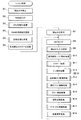
図1は、本発明の一実施形態の遊技機の説明図である。
本実施形態の遊技機10は前面枠12を備え、該前面枠12は本体枠(外枠)11にヒンジ13を介して開閉回動可能に組み付けられている。遊技盤30(図2参照)は前面枠12の表側に形成された収納部(図示省略)に収納されている。また、前面枠(内枠)12には、遊技盤30の前面を覆うカバーガラス(透明部材)14を備えた透明部材保持枠としてのガラス枠15が一体に設けられている。
DESCRIPTION OF EXEMPLARY EMBODIMENTS Hereinafter, preferred embodiments of the invention will be described with reference to the drawings.
FIG. 1 is an explanatory diagram of a gaming machine according to an embodiment of the present invention.
The
また、ガラス枠15の上部には、内部にランプ及びモータを内蔵した照明装置(ムービングライト)16や払出異常報知用のランプ(LED)17が設けられている。また、ガラス枠15の左右には内部にランプ等を内蔵し装飾や演出のための発光をする枠装飾装置18や、音響(例えば、効果音)を発するスピーカ(上スピーカ)19aが設けられている。さらに、前面枠12の下部にもスピーカ(下スピーカ)19bが設けられている。
Further, an illuminating device (moving light) 16 having a built-in lamp and motor and a lamp (LED) 17 for paying out abnormality notification are provided in the upper part of the
また、前面枠12の下部には、図示しない打球発射装置に遊技球を供給する上皿21、遊技機10の裏面側に設けられている球払出装置から払い出された遊技球が流出する上皿球出口22、上皿21が一杯になった状態で払い出された遊技球を貯留する下皿23及び打球発射装置の操作部24等が設けられている。さらに、上皿21の上縁部には、遊技者からの操作入力を受け付けるための操作スイッチを内蔵した演出ボタン25aおよびセレクトボタン25bを備えた入力操作部25が設けられている。
ガラス枠15の下方には、該ガラス枠15とほぼ同一平面をなし下皿23と操作部24とを有するパネル状の下皿ユニット26が設けられ、該下皿ユニット26とガラス枠15とによって前面枠12が構成されており、このうちガラス枠15は左側を支点として回動可能にされている。
In addition, at the lower part of the
Below the
この実施形態の遊技機10においては、遊技者が上記操作部24を回動操作することによって、打球発射装置が、上皿21から供給される遊技球を遊技盤30前面の遊技領域32に向かって発射する。また、遊技者が演出ボタン25aを操作することによって、表示装置41(図2参照)における変動表示ゲーム(飾り特図変動表示ゲーム)において、遊技者の操作を介入させた演出等を行わせることができる。
さらに、上記ガラス枠15の前面には、遊技者が隣接する球貸機から球貸しを受ける場合に操作する球貸ボタン27、球貸機のカードユニットからプリペイドカードを排出させるために操作する排出ボタン28、プリペイドカードの残高を表示する残高表示部(図示省略)等が設けられている。
In the
Further, on the front surface of the
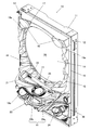
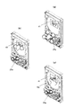
図2〜図4には、上記ガラス枠15の詳しい構成が示されている。図2および図3に示すように、ガラス枠15の下端には、上皿21および操作手段としての入力操作部25、下スピーカ19bを備えた上皿ユニット20が、一体に結合されるように設けられている。
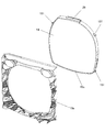
このうち、ガラス枠15は、図3に示すように、開口部を有する樹脂製の前飾りパネル15aと、該前飾りパネル15aとほぼ同様な形状を有しその裏面に接合されるベースプレート15bとを備え、ベースプレート15bには装飾発光用のLEDランプ等が実装されるようになっている。
The detailed structure of the
Among these, as shown in FIG. 3, the
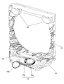
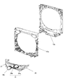
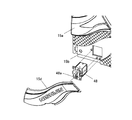
また、図4に示すように、前飾りパネル15aの開口部に対応した形状を有するガラス保持枠15cおよび該ガラス保持枠15cの内側に外縁部が保持されたカバーガラス(透明部材)14が一体にされた状態で、前飾りパネル15aの開口部を覆うようにベースプレート15bの裏面側に装着されるように構成されている。
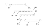
そして、ガラス保持枠15cの上部には、ガラス面において演出表示を可能にするため特殊な加工が施されたカバーガラス14内に向けてガラス面と平行に光を照射する光照射装置29が設けられている。
Further, as shown in FIG. 4, a
A
ガラス保持枠15cの外周面の上下左右4カ所には、係止用の突起151が設けられており、これらの突起151に対応してベースプレート15bの裏面の所定位置には、図5に示すように、回動可能に装着されたロック片152が設けられている。
ガラス保持枠15cをベースプレート15bの裏面に装着する前は、図5(A)のように、ロック片152の先端をガラス保持枠15cから離れる方向へ回動させておき、ガラス保持枠15cをベースプレート15bの裏面に接合させた後に、図5(B)のように、ロック片152の先端をガラス保持枠15cに近づく方向へ回動させると、ロック片152とベースプレート15bの裏面との間に、ガラス保持枠15cの外周面の係止用突起151が挟持されて、装着状態となるように構成されている。
Locking
Before attaching the
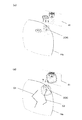
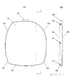
図6には、実施例におけるガラス保持枠15cのより詳細な構造が示されている。このうち(A)は正面図、(B)は図6(A)に示すA−A線に沿った断面図である。図6(B)に示すように、ガラス保持枠15cによって、2枚の透明なガラス14a,14bが保持されており、このうち後方のガラス14bは遊技領域の前面を覆うもので遊技球が衝突するため、衝撃に耐えられる強度を有するものが使用されている。
前方のガラス14a(前面ガラス)は、後方のガラス14bを保護するとともに、上方に配設されている上記光照射装置29からの光を反射することで演出表示を行う導光板として機能する。なお、ガラス保持枠15cの内周面には周方向に沿ってリブ153が形成
されており、リブ153を挟んでガラス14aと14bが配置されることで、所定間隔をおいて平行に保持されるようになっている。
FIG. 6 shows a more detailed structure of the
The
図7には、本実施例の前面ガラス14aにおける表示の例が示されている。前面ガラス14aに、例えば図7に示されている破線G1,G2に沿って断面レの字状の溝を形成しておいて、上方の光照射装置29からガラス内へ光を照射すると、ガラスに形成されている溝で光がガラスの前方へ屈折もしくは反射することで、破線G1,G2のような模様が見えるようになる。本実施例はこの反射模様を表示として利用するものである。上記溝は、前面ガラス14aの側方から光が照射された場合には前方へ光を屈折または反射しないため、模様を見ることができない。つまり、上記溝は異方性反射パターンとみなすことができる。
FIG. 7 shows an example of display on the
次に、光照射装置29の具体例について説明する。光照射装置29は、例えば図8に示すように、両端にボス部291aを有するベース部材291と、複数のLED(発光ダイオード)292が一列に実装されたLED基板293と、複数のLEDに対応して複数の山形の平面レンズ294aが連なるように形成された光拡散部材294と、両端にボス部295aを有しLED基板293と光拡散部材294を上記ベース部材291との間に挟み込んで一体に保持するカバー部材295などからなる。
Next, a specific example of the
光拡散部材294は、カバー部材295によりベース部材291との間に挟み込む際、各レンズ294aが対応するLEDの前方に位置するように配置される。LED基板293と光拡散部材294を挟み込んだ状態でベース部材291に接合されたカバー部材295は、互いのボス部291aとボス部295aに挿通されたネジによって固定される。LED基板293には、演出制御装置と電気的に接続するためのケーブルの端部と結合されるコネクタ296が設けられている。
When the
上記のような構成を有する光照射装置29が、前記前面ガラス14aの上方に下向き姿勢で配置され、各LED292が点灯されると、その光は各レンズ294aで拡散されて、導光板としての前面ガラス14a内に入射され、ガラス面に沿って進行する。なお、光照射装置29は、ガラス枠15の上部ではなく、側部あるいは下部に設けてもよい。
When the
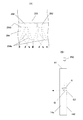
次に、図9を用いて、光照射装置29と前面ガラス14aとによる表示の原理について説明する。図9のうち(A)は光照射装置29の断面構造を拡大して示したもの、(B)は前面ガラス14aの断面構造を模式的に示したものである。
図9(A)に示すように、光拡散部材294は、隣り合う2つのレンズ体294aの谷の部位にLED292の中心が来るように位置決めされている。LED基板293の各LED292が通電されて発光すると、光拡散部材294の平坦をなす裏面294bにLED292からの光が入射される。
Next, the principle of display by the
As shown in FIG. 9A, the
光拡散部材294に入射された光は内部を進行し、各レンズ体294aの円弧状の山形表面より出射されるが、この出射の際にレンズの曲面で屈折する。これにより、LED292の出射光が色々な方向へ拡散されて、前面ガラス14a内に入射されることになる。そのため、複数のLED292から出射された配列方向に強弱のある光が、ほぼ均等に前面ガラス14aの上端面141に照射され、ほぼ均一な光としてガラス内を進行する。
The light incident on the
また、導光板としての前面ガラス14aの裏面には、図9(B)に示すように、前面ガラス14aの上端面141と平行な面f1と、前面ガラス14aの裏面142に対し所定の角度をなす傾斜面f2とを備える断面レの字状の溝G1が形成されている。このような溝は、前面ガラス14aが透明であるため、LEDが消灯している状態では、前方からはほとんど見ることができない。
Further, as shown in FIG. 9B, the back surface of the
一方、LED292が発光すると、出射された光は、前面ガラス14aの上面141から入光して前面ガラス14a内をガラス面と平行に進行し、垂直面f1では屈折せずにそのまま透過し、傾斜面f2に当ると屈折して前面ガラス14aの上面141の前面側に導かれる。この光の屈折により傾斜面f2が発光して見えるようになる。なお、傾斜面f2では光の反射も起きるが、この実施例では、屈折が多くなるように傾斜面f2の角度が設定されている。
そして、このような溝G1を、前面ガラス14aの裏面に、表示したい模様や情報に応じて複数刻み込み、前面ガラス14aの端面から光を照射することにより、溝で光が屈折され模様が表示(発現)されるようになる。
On the other hand, when the
Then, a plurality of such grooves G1 are engraved on the back surface of the
なお、ここでは前面ガラス14aの溝における光の屈折で模様が発現されるようにしたものを説明したが、反射光が多くなるように傾斜面f2の角度を設定することで、溝における光の反射で模様が発現されるように溝G1を形成することも可能である。また、傾斜面f2での屈折もしくは反射で光が半減するような場合にも、背景の色との関係からLEDの発光色を工夫することで、模様が見え易くなるようにすることができる。
また、前面ガラス14aの裏面側ではなく表面側に、断面レの字状の溝を形成するようにしてもよい。溝の断面形状もレの字状に限定されず、V字状等であってもよい。実施例のように、前面ガラス14aの裏面側に溝を形成することによって、汚れが付着しにくくなって表示の低下を防止することができる。表示機能を有するカバーガラス14の代わりに、常態において透明な透過型液晶パネルを設けるようにしてもよい。
In addition, although what demonstrated the pattern by the refraction of the light in the groove | channel of the
Moreover, you may make it form the groove | channel of a cross-section letter shape in the surface side instead of the back surface side of the
以上の説明から、上記実施例には、表示装置41の前方に配置される前面表示装置は、表示部として機能し、表面に画像を表す異方性反射パターンが形成された透明な導光板と、該導光板に対して所定の方向から光を照射する光源とを備え、前記光源を発光させて前記画像を表示状態にするようにした発明が含まれることが分かる。
そして、かかる発明によれば、前面表示装置の導光板は、該導光板に対して所定の方向からの入光がない場合には当該前面表示装置の後方の表示装置を視認可能であるので、導光板への入光の有無により、表示装置による表示と、表示装置および前面表示装置による表示とを切り替えることで、効果的に遊技の興趣を高めることができる。また、異方性反射パターンが形成された導光板は、透過型液晶パネルなどとは異なり、表示装置の表示輝度を下げることがないとともに、簡単な構造であり安価に実現することができる。
From the above description, in the above embodiment, the front display device disposed in front of the
And according to this invention, the light guide plate of the front display device can visually recognize the display device behind the front display device when there is no incident light from the predetermined direction with respect to the light guide plate. By switching between display by the display device and display by the display device and the front display device depending on whether light is incident on the light guide plate, it is possible to effectively increase the interest of the game. In addition, unlike a transmissive liquid crystal panel or the like, a light guide plate on which an anisotropic reflection pattern is formed does not lower the display luminance of the display device, and has a simple structure and can be realized at low cost.
また、上記実施例には、前記前面表示装置は、透明部材保持枠としてのガラス保持枠に設けられ、前記導光板は前記透明部材保持枠により保持される前記透明部材の一部であるようにした発明が含まれることが分かる。
そして、かかる発明によれば、遊技者に一番近いところで前面表示装置の画像が表示されることになり、遊技者が演出を体感しやすい。また、表示装置と前面表示装置との距離も保たれるため、表示装置により表示される立体動画像の前後への移動が視認し易い演出を行うことができる。
In the embodiment, the front display device is provided on a glass holding frame as a transparent member holding frame, and the light guide plate is a part of the transparent member held by the transparent member holding frame. It can be seen that the present invention is included.
And according to this invention, the image of a front display apparatus will be displayed in the place nearest to a player, and it is easy for a player to experience production. In addition, since the distance between the display device and the front display device is also maintained, it is possible to produce an effect in which the movement of the stereoscopic moving image displayed by the display device is easily visible.
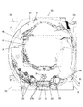
次に、図10を用いて遊技盤30の一例について説明する。図10は、本実施形態の遊技盤30の正面図である。
遊技盤30の表面には、ガイドレール31で囲われた略円形状の遊技領域32が形成されている。遊技領域32は、遊技盤30の四隅に各々設けられた樹脂製のサイドケース33及びガイドレール31に囲繞されて構成される。そして、遊技領域32の前方を覆うように、光の照射により模様等を表示可能なガラス14aおよび光照射装置29を備えた前記ガラス枠15が配置される。
Next, an example of the
On the surface of the
この実施例の遊技盤においては、遊技領域32のほぼ中央に表示装置41を備えたセン
ターケース40が配置されている。表示装置41は、センターケース40に設けられた凹部に、センターケース40の前面より奥まった位置に取り付けられている。即ち、センターケース40は表示装置41の表示領域の周囲を囲い、表示装置41の表示面よりも前方へ突出するように形成されている。ガラス枠15に保持されたガラス14aにて前述したような表示を行う代わりに、図10に破線で示すように、センターケース40の前面側に、溝を形成したガラスを設け、このガラスにて光の照射による表示を行うように構成してもよい。
In the game board of this embodiment, a
表示装置41は、例えば、LCD(液晶表示器)、CRT(ブラウン管)等の表示画面を有する装置で構成されている。表示画面の画像を表示可能な領域(表示領域)には、複数の識別情報(特別図柄)や特図変動表示ゲームを演出するキャラクタや演出効果を高める背景画像等が表示される。表示装置41の表示画面においては、識別情報として割り当てられた複数の特別図柄が変動表示(可変表示)されて、特図変動表示ゲームに対応した飾り特図変動表示ゲームが行われる。また、表示画面には遊技の進行に基づく演出のための画像(例えば、大当たり表示画像、ファンファーレ表示画像、エンディング表示画像等)が表示される。
The
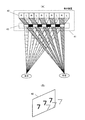
さらに、本実施形態では、表示装置41として立体画像を表示可能なものが使用されており、変動表示ゲーム用の識別図柄(例えば、「777」等)や演出画像を立体的に表示できるように構成されている。
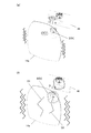
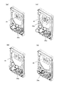
ここで、立体画像を表示可能な表示装置41の一例について説明する。図11(A)はパララックスバリア方式の表示装置の原理を示す。図11(A)において、上下方向は表示装置の左右方向に対応しており、表示装置の液晶パネル42の水平方向の画素には、左画像Lと右画像Rとが交互に表示されるように画像データ処理が行われる。左画像Lとは遊技者の左目に対応する画像であり、右画像Rとは遊技者の右目に対応する画像である。なお、液晶パネル42の裏面側にはバックライト部が配置され、液晶パネルを後方から照らしている。
Further, in the present embodiment, a
Here, an example of the
液晶パネル42の前方(図では左方)には、パララックスバリア部43が配置される。このパララックスバリア部43は、バリア43aとスリット43bが交互に設けられており、バリア43aは閉鎖部分であって液晶パネル42から光を遮断し、スリット43bは開口部分であって液晶パネル42から光を通過させることができるもので、スリット43bは所定のピッチで形成されている。したがって、スリット43bとスリット43bとの間がバリア43aとなって画像の一部を遮るようになり、遊技者の目を所定の位置に位置させることにより、右目には右目用の画像Rだけが見え、左目には左目用の画像Lだけが見えることになる。その結果、遊技者には、図11(B)に示すように、液晶パネル42に表示されている画像が立体的に見えることになる。
A
図10に戻って説明すると、遊技領域32のセンターケース40の左側には、普通図柄始動ゲート(普図始動ゲート)34が設けられている。センターケース40の左下側には、三つの一般入賞口35が配置され、センターケース40の右下側には、一つの一般入賞口35が配置されている。
これら一般入賞口35、…には、各一般入賞口35に入った遊技球を検出するための入賞口スイッチ35a〜35n(図11参照)が配設されている。
また、センターケース40の下方には、特図変動表示ゲームの開始条件を与える始動入賞口36が設けられ、その直下には上部に逆「ハ」の字状に開いて遊技球が流入し易い状態に変換する一対の可動部材37b、37bを備えるとともに内部に第2始動入賞口を有する普通変動入賞装置(普電)37が配設されている。
Returning to FIG. 10, a normal symbol start gate (ordinary start gate) 34 is provided on the left side of the
In each of the general winning
A
普通変動入賞装置37の一対の開閉部材37b,37bは、常時は遊技球の直径程度の
間隔をおいた閉じた閉状態(遊技者にとって不利な状態)を保持している。ただし、普通変動入賞装置37の上方には、始動入賞口36が設けられているので、閉じた状態では遊技球が入賞できないようになっている。
そして、普図変動表示ゲームの結果が所定の停止表示態様となった場合には、駆動装置としての普電ソレノイド37c(図12参照)によって、逆「ハ」の字状に開いて普通変動入賞装置37に遊技球が流入し易い開状態(遊技者にとって有利な状態)に変化させられるようになっている。
さらに、普通変動入賞装置37の下方には、特図変動表示ゲームの結果によって遊技球を受け入れない状態と受け入れ易い状態とに変換可能な特別変動入賞装置(大入賞口)38が配設されている。
The pair of opening / closing
Then, when the result of the normal variation display game becomes a predetermined stop display mode, it is opened in a reverse “C” shape by the general
Further, a special variable winning device (large winning mouth) 38 that can be converted into a state where a game ball is not accepted and a state where it is easy to accept depending on the result of the special figure changing display game is arranged below the normal
特別変動入賞装置38は、上端側が手前側に倒れる方向に回動して開放可能になっているアタッカ形式の開閉扉を有しており、補助遊技としての特図変動表示ゲームの結果如何によって大入賞口を閉じた状態(遊技者にとって不利な閉塞状態)から開放状態(遊技者にとって有利な状態)に変換する。
即ち、特別変動入賞装置38は、例えば、駆動装置としての大入賞口ソレノイド38b(図11参照)により駆動される開閉扉によって開閉される大入賞口を備え、特別遊技状態中は、大入賞口を閉じた状態から開いた状態に変換することにより大入賞口内への遊技球の流入を容易にさせ、遊技者に所定の遊技価値(賞球)を付与するようになっている。
The special
That is, the special variable
なお、大入賞口の内部(入賞領域)には、当該大入賞口に入った遊技球を検出する検出手段としてのカウントスイッチ38a(図11参照)が配設されている。
特別変動入賞装置38の下方には、入賞口などに入賞しなかった遊技球を回収するアウト口39が設けられている。
また、遊技領域32の外側(例えば、遊技盤30の上部)には、特図変動表示ゲームをなす第1特図変動表示ゲームや第2特図変動表示ゲーム及び普図始動ゲート34への入賞をトリガとする普図変動表示ゲームを一箇所で実行する一括表示装置50が設けられている。
In addition, a
Below the special variable winning
Also, outside the game area 32 (for example, at the top of the game board 30), the first special figure fluctuation display game and the second special figure fluctuation display game that form the special figure fluctuation display game, and the winning for the normal
一括表示装置50は、7セグメント型の表示器(LEDランプ)等で構成された第1特図変動表示ゲーム用の第1特図変動表示部(特図1表示器)51及び第2特図変動表示ゲーム用の第2特図変動表示部(特図2表示器)52を備える。また、LEDランプで構成された普図変動表示ゲーム用の変動表示部(普図表示器)、同じくLEDランプで構成された各変動表示ゲームの始動記憶数報知用の記憶表示部、遊技状態を報知する表示部、エラーを表示するエラー表示部、大当り時のラウンド数(特別変動入賞装置38の開閉回数)を表示するラウンド表示部などからなるLED表示部53が設けられている。
The
特図1表示器と特図2表示器における特図変動表示ゲームは、例えば変動表示ゲームの実行中、即ち、表示装置41において飾り特図変動表示ゲームを行っている間は、中央のセグメントを点滅駆動させて変動中であることを表示する。そして、ゲームの結果が「はずれ」のときは、はずれの結果態様として例えば中央のセグメントを点灯状態にし、ゲームの結果が「当り」のときは、当りの結果態様(特別結果態様)としてはずれの結果態様以外の結果態様(例えば「3」や「7」の数字等)を点灯状態にしてゲーム結果を表示する。
The special figure fluctuation display game in the special figure 1 display and the special figure 2 display is, for example, while the fluctuation display game is being executed, that is, while the decoration special figure fluctuation display game is being performed on the
本実施形態の遊技機10では、図示しない発射装置から遊技領域32に向けて遊技球(パチンコ球)が打ち出されることによって遊技が行われる。打ち出された遊技球は、遊技領域32内の各所に配置された障害釘や風車等の方向転換部材によって転動方向を変えながら遊技領域32を流下し、普図始動ゲート34、一般入賞口35、始動入賞口36、普通変動入賞装置37又は特別変動入賞装置38に入賞するか、遊技領域32の最下部に設
けられたアウト口39へ流入し遊技領域から排出される。そして、一般入賞口35、始動入賞口36、普通変動入賞装置37又は特別変動入賞装置38に遊技球が入賞すると、入賞した入賞口の種類に応じた数の賞球が、払出制御装置200によって制御される払出ユニットから、前面枠12の上皿21又は下皿23に排出される。
In the
一方、普図始動ゲート34内には、該普図始動ゲート34を通過した遊技球を検出するための非接触型のスイッチなどからなるゲートスイッチ34a(図11参照)が設けられており、遊技領域32内に打ち込まれた遊技球が普図始動ゲート34内を通過すると、ゲートスイッチ34aにより検出されて普図変動表示ゲームが行われる。
また、普図変動表示ゲームを開始できない状態、例えば、既に普図変動表示ゲームが行われ、その普図変動表示ゲームが終了していない状態や、普図変動表示ゲームが当って普通変動入賞装置37が開状態に変換されている場合に、普図始動ゲート34を遊技球が通過すると、普図始動記憶数の上限数未満でならば、普図始動記憶数が加算(+1)されて普図始動記憶が1つ記憶されることとなる。この普図始動入賞の記憶数は、一括表示装置50のLED表示部53の始動入賞数報知用の記憶表示部に表示される。
On the other hand, a
In addition, the normal variation display game cannot be started, for example, the normal variation display game has already been played and the normal variation display game has not been completed, When 37 is converted to the open state and the game ball passes through the general figure start
また、普図始動記憶には、普図変動表示ゲームの当りはずれを決定するための当り判定用乱数値が記憶されるようになっていて、この当り判定用乱数値が判定値と一致した場合に、当該普図変動表示ゲームが当りとなって特定の結果態様(特定結果)が導出されることとなる。
普図変動表示ゲームは、一括表示装置50に設けられたLED表示部53の変動表示部(普図表示器)で実行されるようになっている。普図表示器は、普通識別情報(普図、普通図柄)として点灯状態の場合に当たりを示し、消灯状態の場合にはずれを示すLEDから構成され、このLEDを点滅表示することで普通識別情報の変動表示を行い、所定の変動表示時間の経過後、LEDを点灯又は消灯することで結果を表示するようになっている。
In addition, in the normal chart start memory, a random number value for hit determination for determining the hit error of the normal figure fluctuation display game is stored, and when the random number value for hit determination coincides with the determination value In addition, a specific result mode (specific result) is derived by hitting the common map change display game.
The general-purpose variable display game is executed by a variable display unit (standard map display) of the
なお、普通識別情報として例えば数字、記号、キャラクタ図柄などを用い、これを所定時間変動表示させた後、停止表示させることにより行うように構成しても良い。この普図変動表示ゲームの停止表示が特定結果となれば、普図の当りとなって、普通変動入賞装置37の一対の可動部材37bが所定時間(例えば、0.3秒間)開放される開状態となる。これにより、普通変動入賞装置37の内部の第2始動入賞口へ遊技球が入賞し易くなり、第2特図変動表示ゲームが実行される回数が多くなる。
Note that, for example, numbers, symbols, character designs, and the like may be used as the normal identification information, which is displayed by variably displaying for a predetermined time and then stopped. If the stop display of the usual figure change display game is a specific result, the pair of
普図始動ゲート34への通過検出時に抽出した普図乱数値が当たり値であるときには、LED表示部53の普図表示器に表示される普通図柄が当たり状態で停止し、当たり状態となる。このとき、普通変動入賞装置37は、内蔵されている普電ソレノイド37c(図11参照)が駆動されることにより、可動部材37bが所定の時間(例えば、0.3秒間)だけ開放する状態に変換され、遊技球の入賞が許容される。
When the common random number value extracted at the time of detecting passage to the general figure start
始動入賞口36への入賞球及び普通変動入賞装置37への入賞球は、それぞれは内部に設けられた始動口1スイッチ36aと始動口2スイッチ37aによって検出される。始動入賞口36へ入賞した遊技球は第1特図変動表示ゲームの始動入賞球として検出され、所定の上限数(例えば、4個)を限度に記憶されるとともに、普通変動入賞装置37へ入賞した遊技球は第2特図変動表示ゲームの始動入賞球として検出され、所定の上限数(例えば、4個)を限度に記憶される。
The winning ball to the
また、この始動入賞球の検出時にそれぞれ大当り乱数値や大当り図柄乱数値、並びに各変動パターン乱数値が抽出され、抽出された乱数値は、遊技制御装置100(図11参照)内の特図記憶領域(RAMの一部)に特図始動記憶として各々所定回数(例えば、最大
で4回分)を限度に記憶される。そして、この特図始動記憶の記憶数は、一括表示装置50の始動入賞数報知用の記憶表示部に表示されるとともに、センターケース40の表示装置41においても表示される。
In addition, when the starting winning ball is detected, a big hit random number value, a big hit symbol random number value, and each variation pattern random number value are extracted. Each area (a part of the RAM) is stored as a special figure start memory for a predetermined number of times (for example, a maximum of four times). The number stored in the special chart start memory is displayed on the memory display section for notifying the start winning number of the
遊技制御装置100は、始動入賞口36若しくは普通変動入賞装置37への入賞、又はそれらの始動記憶に基づいて、一括表示装置50に設けられた特図1表示器または特図2表示器(変動表示装置)で第1または第2特図変動表示ゲームを行う。
第1特図変動表示ゲーム及び第2特図変動表示ゲームは、複数の特別図柄(特図、識別情報)を変動表示したのち、所定の結果態様を停止表示することで行われる。また、表示装置41にて各特図変動表示ゲームに対応して複数種類の識別情報(例えば、数字、記号、キャラクタ図柄など)を変動表示させる飾り特図変動表示ゲームが実行されるようになっている。
そして、特図変動表示ゲームの結果として、特図1表示器若しくは特図2表示器の表示態様が特別結果態様となった場合には、大当りとなって特別遊技状態(いわゆる、大当り状態)となる。また、これに対応して表示装置41の表示態様も特別結果態様となる。
The
The first special figure fluctuation display game and the second special figure fluctuation display game are performed by variably displaying a plurality of special symbols (special figures, identification information) and then stopping and displaying a predetermined result form. In addition, a decorative special figure fluctuation display game for displaying a plurality of types of identification information (for example, numbers, symbols, character designs, etc.) corresponding to each special figure fluctuation display game on the
As a result of the special figure change display game, when the display mode of the special figure 1 display or the special figure 2 display becomes a special result mode, a special game state (so-called big hit state) is obtained. Become. Correspondingly, the display mode of the
表示装置41における飾り特図変動表示ゲームは、例えば前述した数字等で構成される飾り特別図柄(識別情報)が左(第一特別図柄)、右(第二特別図柄)、中(第三特別図柄)の順に変動表示を開始して、所定時間後に変動している図柄を順次停止させて、特図変動表示ゲームの結果を表示することで行われる。また、表示装置41では、特図始動記憶数に対応する飾り特別図柄による変動表示ゲームを行うとともに、興趣向上のためにキャラクタの出現など多様な演出表示が行われる。
In the decorative special symbol variation display game on the
なお、特図1表示器、特図2表示器は、別々の表示器でも良いし同一の表示器でも良いが、各々独立して、また、同時には実行しないように各特図変動表示ゲームが表示される。また、表示装置41も、第1特図変動表示ゲームと第2特図変動表示ゲームで別々の表示装置や別々の表示領域を使用するとしても良いし、同一の表示装置や表示領域を使用するとしても良いが、各々独立して、また、同時には実行しないように飾り特図変動表示ゲームが表示される。また、遊技機10に特図1表示器、特図2表示器を備えずに、表示装置41のみで特図変動表示ゲームを実行するようにしても良い。
Note that the special figure 1 display and the special figure 2 display may be separate displays or the same display, but each special figure variation display game is not to be executed independently or simultaneously. Is displayed. In addition, the
また、第2特図変動表示ゲームは、第1特図変動表示ゲームよりも優先して実行されるようになっている。即ち、第1特図変動表示ゲームと第2特図変動表示ゲームの始動記憶がある場合であって、特図変動表示ゲームの実行が可能となった場合は、第2特図変動表示ゲームが実行されるようになっている。
また、第1特図変動表示ゲーム(第2特図変動表示ゲーム)が開始可能な状態で、且つ、始動記憶数が0の状態で、始動入賞口36(若しくは、普通変動入賞装置37)に遊技球が入賞すると、始動権利の発生に伴って始動記憶が記憶されて、始動記憶数が1加算されるととともに、直ちに始動記憶に基づいて、第1特図変動表示ゲーム(第2特図変動表示ゲーム)が開始され、この際に始動記憶数が1減算される。
Further, the second special figure variation display game is executed with priority over the first special figure variation display game. That is, if there is a start memory of the first special figure fluctuation display game and the second special figure fluctuation display game, and the execution of the special figure fluctuation display game becomes possible, the second special figure fluctuation display game is It is supposed to be executed.
In addition, in the state where the first special figure fluctuation display game (second special figure fluctuation display game) can be started and the number of start memories is zero, the start winning opening 36 (or the normal fluctuation prize winning device 37) is entered. When the game ball wins, the start memory is stored as the start right is generated, the start memory number is incremented by 1, and the first special figure variation display game (second special figure) is immediately added based on the start memory. (Variable display game) is started, and at this time, the start memory number is decremented by one.
一方、第1特図変動表示ゲーム(第2特図変動表示ゲーム)が直ちに開始できない状態、例えば、既に第1若しくは第2特図変動表示ゲームが行われ、その特図変動表示ゲームが終了していない状態や、特別遊技状態となっている場合に、始動入賞口36(若しくは、普通変動入賞装置37)に遊技球が入賞すると、始動記憶数が上限数未満ならば、始動記憶数が1加算されて始動記憶が1つ記憶されることになる。そして、始動記憶数が1以上となった状態で、第1特図変動表示ゲーム(第2特図変動表示ゲーム)が開始可能な状態(前回の特図変動表示ゲームの終了若しくは特別遊技状態の終了)となると、始動記憶数が1減算されるとともに、記憶された始動記憶に基づいて第1特図変動表示ゲーム(第2特図変動表示ゲーム)が開始される。
なお、以下の説明において、第1特図変動表示ゲームと第2特図変動表示ゲームを区別しない場合は、単に特図変動表示ゲームと称する。
On the other hand, a state in which the first special figure fluctuation display game (second special figure fluctuation display game) cannot be started immediately, for example, the first or second special figure fluctuation display game has already been performed, and the special figure fluctuation display game has ended. When the game ball is won in the start winning opening 36 (or the normal variable prize winning device 37) in a state that is not in a special state or in a special game state, the start memory number is 1 if the start memory number is less than the upper limit number. By adding, one start memory is stored. Then, in a state where the starting memory number becomes 1 or more, a state in which the first special figure fluctuation display game (second special figure fluctuation display game) can be started (the end of the previous special figure fluctuation display game or the special game state) (End), the start memory number is decremented by 1, and the first special figure fluctuation display game (second special figure fluctuation display game) is started based on the stored start memory.
In the following description, when the first special figure fluctuation display game and the second special figure fluctuation display game are not distinguished, they are simply referred to as a special figure fluctuation display game.
なお、特に限定されるわけではないが、上記始動入賞口36内の始動口1スイッチ36a、普通変動入賞装置37内の始動口2スイッチ37a、ゲートスイッチ34a、一般入賞口スイッチ35a〜35n、カウントスイッチ38aには、磁気検出用のコイルを備え該コイルに金属が近接すると磁界が変化する現象を利用して遊技球を検出する非接触型の磁気近接センサ(以下、近接スイッチと称する)が使用されている。遊技機10のガラス枠15等に設けられた前枠開放検出スイッチ63や前面枠(遊技枠)12等に設けられた遊技枠開放検出スイッチ64には、機械的な接点を有するマイクロスイッチを用いることができる。
Although not particularly limited, the starting
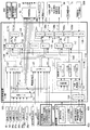
図12は、本実施形態のパチンコ遊技機10の制御システムの構成例を示す。
遊技機10は遊技制御装置100を備え、遊技制御装置100は、遊技を統括的に制御する主制御装置(主基板)であって、遊技用マイクロコンピュータ(以下、遊技用マイコンと称する)111を有するCPU部110と、入力ポートを有する入力部120と、出力ポートやドライバなどを有する出力部130、CPU部110と入力部120と出力部130との間を接続するデータバス140などからなる。
FIG. 12 shows a configuration example of a control system of the
The
上記CPU部110は、アミューズメントチップ(IC)と呼ばれる遊技用マイコン(CPU)111と、入力部120内の近接スイッチ用のインタフェースチップ(近接I/F)121からの信号(始動入賞検出信号)を論理反転して遊技用マイコン111に入力させるインバータなどからなる反転回路112と、水晶振動子のような発振子を備え、CPUの動作クロックやタイマ割込み、乱数生成回路の基準となるクロックを生成する発振回路(水晶発振器)113などを有する。遊技制御装置100及び該遊技制御装置100によって駆動されるソレノイドやモータなどの電子部品には、電源装置400で生成されたDC32V,DC12V,DC5Vなど所定のレベルの直流電圧が供給されて動作可能にされる。
The
電源装置400は、24Vの交流電源から上記DC32Vの直流電圧を生成するAC−DCコンバータやDC32Vの電圧からDC12V,DC5Vなどのより低いレベルの直流電圧を生成するDC−DCコンバータなどを有する通常電源部410と、遊技用マイコン111の内部のRAMに対して停電時に電源電圧を供給するバックアップ電源部420と、停電監視回路や初期化スイッチを有し遊技制御装置100に停電の発生、回復を知らせる停電監視信号や初期化スイッチ信号、リセット信号などの制御信号を生成して出力する制御信号生成部430などを備える。
The
この実施形態では、電源装置400は、遊技制御装置100と別個に構成されているが、バックアップ電源部420及び制御信号生成部430は、別個の基板上あるいは遊技制御装置100と一体、即ち、主基板上に設けるように構成してもよい。遊技盤30及び遊技制御装置100は機種変更の際に交換の対象となるので、実施形態のように、電源装置400若しくは主基板とは別の基板にバックアップ電源部420及び制御信号生成部430を設けることにより、交換の対象から外しコストダウンを図ることができる。
In this embodiment, the
上記バックアップ電源部420は、電解コンデンサのような大容量のコンデンサ1つで構成することができる。バックアップ電源は、遊技制御装置100の遊技用マイコン111(特に内蔵RAM)に供給され、停電中あるいは電源遮断後もRAMに記憶されたデータが保持されるようになっている。制御信号生成部430は、例えば通常電源部410で生成された32Vの電圧を監視してそれが例えば17V以下に下がると停電発生を検出して停電監視信号を変化させるとともに、所定時間後にリセット信号を出力する。また、電
源投入時や停電回復時にもその時点から所定時間経過後にリセット信号を出力する。
The backup
初期化スイッチ信号は初期化スイッチがオン状態にされたときに生成される信号で、遊技用マイコン111内のRAM111C及び払出制御装置200内のRAMに記憶されている情報を強制的に初期化する。特に限定されるわけではないが初期化スイッチ信号は電源投入時に読み込まれ、停電監視信号は遊技用マイコン111が実行するメインプログラムのメインループの中で繰り返し読み込まれる。リセット信号は強制割込み信号の一種であり、制御システム全体をリセットさせる。
The initialization switch signal is a signal generated when the initialization switch is turned on, and forcibly initializes information stored in the
遊技用マイコン111は、遊技を統括的に制御する遊技制御手段を構成している。具体的には、遊技用マイコン111は、CPU(中央処理ユニット:マイクロプロセッサ)111A、読出し専用のROM(リードオンリメモリ)111B及び随時読出し書込み可能なRAM(ランダムアクセスメモリ)111Cを備える。
ROM111Bは、遊技制御のための不変の情報(プログラム、固定データ、各種乱数の判定値等)を不揮発的に記憶し、RAM111Cは、遊技制御時にCPU111Aの作業領域や各種信号や乱数値の記憶領域として利用される。ROM111B又はRAM111Cとして、EEPROMのような電気的に書換え可能な不揮発性メモリを用いてもよい。
The
The
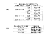
また、ROM111Bは、例えば、特図変動表示ゲームの実行時間、演出内容、リーチ状態の発生の有無などを規定する変動パターンを決定するための変動パターンテーブルを記憶している。
変動パターンテーブルとは、始動記憶として記憶されている変動パターン乱数1〜3をCPU111Aが参照して変動パターンを決定するためのテーブルである。また、変動パターンテーブルには、結果がはずれとなる場合に選択されるはずれ変動パターンテーブル、結果が15R当りや2R当りとなる場合に選択される大当り変動パターンテーブル等が含まれる。さらに、これらのパターンテーブルには、後半変動パターンテーブル、前半変動パターンテーブルが含まれている。
In addition, the
The variation pattern table is a table for the
また、リーチ(リーチ状態)とは、表示状態が変化可能な表示装置を有し、該表示装置が時期を異ならせて複数の表示結果を導出表示し、該複数の表示結果が予め定められた特別結果態様となった場合に、遊技状態が遊技者にとって有利な遊技状態(特別遊技状態)となる遊技機10において、複数の表示結果の一部がまだ導出表示されていない段階で、既に導出表示されている表示結果が特別結果態様となる条件を満たしている表示状態をいう。また、別の表現をすれば、リーチ状態とは、表示装置の変動表示制御が進行して表示結果が導出表示される前段階にまで達した時点でも、特別結果態様となる表示条件からはずれていない表示態様をいう。そして、例えば、特別結果態様が揃った状態を維持しながら複数の変動表示領域による変動表示を行う状態(いわゆる全回転リーチ)もリーチ状態に含まれる。また、リーチ状態とは、表示装置の表示制御が進行して表示結果が導出表示される前段階にまで達した時点での表示状態であって、表示結果が導出表示される以前に決定されている複数の変動表示領域の表示結果の少なくとも一部が特別結果態様となる条件を満たしている場合の表示状態をいう。
Reach (reach state) has a display device whose display state can change, and the display device derives and displays a plurality of display results at different times, and the plurality of display results are predetermined. In the
よって、例えば、特図変動表示ゲームに対応して表示装置に表示される飾り特図変動表示ゲームが、表示装置における左、中、右の変動表示領域の各々で所定時間複数の識別情報を変動表示した後、左、右、中の順で変動表示を停止して結果態様を表示するものである場合、左、右の変動表示領域で、特別結果態様となる条件を満たした状態(例えば、同一の識別情報)で変動表示が停止した状態がリーチ状態となる。またこの他に、すべての変動表示領域の変動表示を一旦停止した時点で、左、中、右のうち何れか二つの変動表示領域で特別結果態様となる条件を満たした状態(例えば、同一の識別情報となった状態、
ただし特別結果態様は除く)をリーチ状態とし、このリーチ状態から残りの一つの変動表示領域を変動表示するようにしても良い。
Thus, for example, a decorative special figure fluctuation display game displayed on a display device corresponding to a special figure fluctuation display game fluctuates a plurality of identification information for a predetermined time in each of the left, middle, and right fluctuation display areas on the display device. After displaying, when the display of the result mode is stopped in the order of left, right, and middle, the condition that becomes the special result mode is satisfied in the left and right variable display areas (for example, The state in which the variable display is stopped with the same identification information) is the reach state. In addition to this, when the variable display of all the variable display areas is temporarily stopped, the condition that the special result mode is satisfied in any two of the left, middle, and right variable display areas (for example, the same The state of identification information,
However, it is also possible to set the reach state except for the special result mode), and display the remaining one variable display area in a variable manner from the reach state.
そして、このリーチ状態には複数のリーチ演出が含まれ、特別結果態様が導出される可能性が異なる(信頼度が異なる)リーチ演出として、ノーマルリーチ、スペシャル1リーチ、スペシャル2リーチ、スペシャル3リーチ、プレミアリーチ等が設定されている。なお、信頼度は、リーチなし<ノーマルリーチ<スペシャル1リーチ<スペシャル2リーチ<スペシャル3リーチ<プレミアリーチの順に高くなるようになっている。また、このリーチ状態は、少なくとも特図変動表示ゲームで特別結果態様が導出される場合(大当りとなる場合)における変動表示態様に含まれるようになっている。即ち、特図変動表示ゲームで特別結果態様が導出されないと判定すると(はずれとなる場合)における変動表示態様に含まれることもある。よって、リーチ状態が発生した状態は、リーチ状態が発生しない場合に比べて大当りとなる可能性の高い状態である。 This reach state includes a plurality of reach productions, and the possibility that a special result mode is derived (different reliability) includes normal reach, special 1 reach, special 2 reach, special 3 reach, Premier reach etc. are set. The reliability increases in the order of no reach <normal reach <special 1 reach <special 2 reach <special 3 reach <premier reach. In addition, this reach state is included in a variable display mode at least in a case where a special result mode is derived in a special figure variable display game (when a big hit is achieved). That is, when it is determined that the special result mode is not derived in the special figure variable display game (when it is out of date), it may be included in the variable display mode. Therefore, the state in which the reach state has occurred is a state that is more likely to be a big hit than the case in which the reach state does not occur.
CPU111Aは、ROM111B内の遊技制御用プログラムを実行して、払出制御装置200や演出制御装置300に対する制御信号(コマンド)を生成したりソレノイドや表示装置の駆動信号を生成して出力して遊技機10全体の制御を行う。
また、図示しないが、遊技用マイコン111は、特図変動表示ゲームの大当り判定用乱数や大当りの図柄を決定するための大当り図柄用乱数、特図変動表示ゲームでの変動パターン(各種リーチやリーチ無しの変動表示における変動表示ゲームの実行時間等を含む)を決定するための変動パターン乱数、普図変動表示ゲームの当たり判定用乱数等を生成するための乱数生成回路と、発振回路113からの発振信号(原クロック信号)に基づいてCPU111Aに対する所定周期(例えば、4ミリ秒)のタイマ割込み信号や乱数生成回路の更新タイミングを与えるクロックを生成するクロックジェネレータを備えている。
The
Although not shown, the
また、CPU111Aは、後述する特図ゲーム処理(図17参照)における始動口スイッチ監視処理(ステップA1)や特図普段処理(ステップA9)にて、ROM111Bに記憶されている複数の変動パターンテーブルの中から、何れか一の変動パターンテーブルを取得する。具体的には、CPU111Aは、特図変動表示ゲームの遊技結果(大当り或いははずれ)や、現在の遊技状態としての特図変動表示ゲームの確率状態(通常確率状態或いは高確率状態)、現在の遊技状態としての普通変動入賞装置37の動作状態(通常動作状態或いは時短動作状態)、始動記憶数などに基づいて、複数の変動パターンテーブルの中から、何れか一の変動パターンテーブルを選択して取得する。
In addition, the
払出制御装置200は、図示しないが、CPU、ROM、RAM、入力インタフェース、出力インタフェース等を備え、遊技制御装置100からの賞球払出し指令(コマンドやデータ)に従って、払出ユニットの払出モータを駆動させ、賞球を払い出させるための制御を行う。また、払出制御装置200は、カードユニットからの貸球要求信号に基づいて払出ユニットの払出モータを駆動させ、貸球を払い出させるための制御を行う。
Although not shown, the
遊技用マイコン111の入力部120には、始動入賞口36内の始動口1スイッチ36a、普通変動入賞装置37内の始動口2スイッチ37a、普図始動ゲート34内のゲートスイッチ34a、一般入賞口スイッチ35a〜35n、カウントスイッチ38aに接続され、これらのスイッチから供給されるハイレベルが11Vでロウレベルが7Vのような負論理の信号が入力され、0V−5Vの正論理の信号に変換するインタフェースチップ(近接I/F)121が設けられている。近接I/F121は、入力の範囲が7V−11Vとされることで、近接スイッチのリード線が不正にショートされたり、スイッチがコネクタから外されたり、リード線が切断されてフローティングになったような異常な状態を検出することができ、異常検知信号を出力するように構成されている。
The
近接I/F121の出力はすべて第2入力ポート122へ供給されデータバス140を介して遊技用マイコン111に読み込まれるとともに、主基板100から中継基板70を介して図示しない試射試験装置へ供給されるようになっている。また、近接I/F121の出力のうち始動口1スイッチ36aと始動口2スイッチ37aの検出信号は、第2入力ポート122の他、反転回路112を介して遊技用マイコン111へ入力されるように構成されている。反転回路112を設けているのは、遊技用マイコン111の信号入力端子が、マイクロスイッチなどからの信号が入力されることを想定し、かつ負論理、即ち、ロウレベル(0V)を有効レベルとして検知するように設計されているためである。
All the outputs of the proximity I /
従って、始動口1スイッチ36aと始動口2スイッチ37aとしてマイクロスイッチを使用する場合には、反転回路112を設けずに直接遊技用マイコン111へ検出信号を入力させるように構成することができる。つまり、始動口1スイッチ36aと始動口2スイッチ37aからの負論理の信号を直接遊技用マイコン111へ入力させたい場合には、近接スイッチを使用することはできない。上記のように近接I/F121は、信号のレベル変換機能を有する。このようなレベル変換機能を可能にするため、近接I/F121には、電源装置400から通常のICの動作に必要な例えば5Vのような電圧の他に、12Vの電圧が供給されるようになっている。
Therefore, when a micro switch is used as the
また、入力部120には、遊技機10の前面枠12等に設けられた不正検出用の磁気センサスイッチ61及び振動センサスイッチ62からの信号及び上記近接I/F121により変換された始動入賞口36内の始動口1スイッチ36a、普通変動入賞装置37内の始動口2スイッチ37a、ゲートスイッチ34a、一般入賞口スイッチ35a〜35n、カウントスイッチ38aからの信号を取り込んでデータバス140を介して遊技用マイコン111に供給する第2入力ポート122が設けられている。第2入力ポート122が保持しているデータは、遊技用マイコン111が第2入力ポート122に割り当てられているアドレスをデコードすることによってイネーブル信号CE1をアサート(有効レベルに変化)することよって、読み出すことができる。後述の他のポートも同様である。
Further, the
さらに、入力部120には、遊技機10のガラス枠15等に設けられた前枠開放検出スイッチ63及び前面枠(遊技枠)12等に設けられた遊技枠開放検出スイッチ64からの信号及び払出制御装置200からの払出異常を示すステータス信号や払出し前の遊技球の不足を示すシュート球切れスイッチ信号、オーバーフローを示すオーバーフロースイッチ信号を取り込んでデータバス140を介して遊技用マイコン111に供給する第1入力ポート123が設けられている。オーバーフロースイッチ信号は、下皿23に遊技球が所定量以上貯留されていること(満杯になったこと)を検出したときに出力される信号である。
Further, the
また、入力部120には、電源装置400からの停電監視信号や初期化スイッチ信号、リセット信号などの信号を遊技用マイコン111等に入力するためのシュミットトリガ回路124が設けられており、シュミットトリガ回路124はこれらの入力信号からノイズを除去する機能を有する。電源装置400からの信号のうち停電監視信号と初期化スイッチ信号は、一旦第1入力ポート123に入力され、データバス140を介して遊技用マイコン111に取り込まれる。つまり、前述の各種スイッチからの信号と同等の信号として扱われる。遊技用マイコン111に設けられている外部からの信号を受ける端子の数には制約があるためである。
Further, the
一方、シュミットトリガ回路124によりノイズ除去されたリセット信号RSTは、遊技用マイコン111に設けられているリセット端子に直接入力されるとともに、出力部130の各ポートに供給される。また、リセット信号RSTは出力部130を介さずに直接中継基板70に出力することで、試射試験装置へ出力するために中継基板70のポート(
図示省略)に保持される試射試験信号をオフするように構成されている。また、リセット信号RSTを中継基板70を介して試射試験装置へ出力可能に構成するようにしてもよい。
On the other hand, the reset signal RST from which noise has been removed by the
The test fire test signal held in (not shown) is turned off. Further, the reset signal RST may be configured to be output to the test firing test apparatus via the
なお、リセット信号RSTは入力部120の各ポート122,123には供給されない。リセット信号RSTが入る直前に遊技用マイコン111によって出力部130の各ポートに設定されたデータはシステムの誤動作を防止するためリセットする必要があるが、リセット信号RSTが入る直前に入力部120の各ポートから遊技用マイコン111が読み込んだデータは、遊技用マイコン111のリセットによって廃棄されるためである。
The reset signal RST is not supplied to the
出力部130は、データバス140に接続され払出制御装置200へ出力する4ビットのデータ信号とデータの有効/無効を示す制御信号(データストローブ信号)及び演出制御装置300へ出力するデータストローブ信号SSTBを生成する第1出力ポート131と、演出制御装置300へ出力する8ビットのデータ信号を生成する第2出力ポート132とを備える。遊技制御装置100から払出制御装置200及び演出制御装置300へは、パラレル通信でデータが送信される。
The
また、出力部130には、演出制御装置300の側から遊技制御装置100へ信号を入力できないようにするため、即ち、片方向通信を保証するために第1出力ポート131からの上記データストローブ信号SSTB及び第2出力ポート132からの8ビットのデータ信号を出力する単方向のバッファ133が設けられている。なお、第1出力ポート131から払出制御装置200へ出力する信号に対してもバッファを設けるようにしてもよい。
In addition, the data strobe signal from the
さらに、出力部130には、データバス140に接続され図示しない認定機関の試射試験装置へ変動表示ゲームの特図図柄情報を知らせるデータや大当りの確率状態を示す信号などを中継基板70を介して出力するバッファ134が実装可能に構成されている。このバッファ134は遊技店に設置される実機(量産販売品)としてのパチンコ遊技機の遊技制御装置(主基板)には実装されない部品である。なお、前記近接I/F121から出力される始動口スイッチなど加工の必要のないスイッチの検出信号は、バッファ134を通さずに中継基板70を介して試射試験装置へ供給される。
In addition, the
一方、磁気センサスイッチ61や振動センサスイッチ62のようにそのままでは試射試験装置へ供給できない検出信号は、一旦遊技用マイコン111に取り込まれて他の信号若しくは情報に加工されて、例えば遊技機が遊技制御できない状態であることを示すエラー信号としてデータバス140からバッファ134、中継基板70を介して試射試験装置へ供給される。なお、中継基板70には、上記バッファ134から出力された信号を取り込んで試射試験装置へ供給するポートや、バッファを介さないスイッチの検出信号の信号線を中継して伝達するコネクタなどが設けられている。中継基板70上のポートには、遊技用マイコン111から出力されるチップイネーブル信号CEも供給され、該信号CEにより選択制御されたポートの信号が試射試験装置へ供給されるようになっている。
On the other hand, detection signals such as the
また、出力部130には、データバス140に接続され特別変動入賞装置38を開成させるソレノイド(大入賞口ソレノイド)38bや普通変動入賞装置37の可動部材37bを開成させるソレノイド(普電ソレノイド)37cの開閉データと、一括表示装置50のLEDのカソード端子が接続されているデジット線のオン/オフデータを出力するための第3出力ポート135、一括表示装置50に表示する内容に応じてLEDのアノード端子が接続されているセグメント線のオン/オフデータを出力するための第4出力ポート136、大当り情報など遊技機10に関する情報を外部情報端子71へ出力するための第5出力ポート137が設けられている。外部情報端子71から出力された遊技機10に関する
情報は、例えば遊技店に設置された情報収集端末や遊技場内部管理装置(図示省略)に供給される。
In addition, the
さらに、出力部130には、第3出力ポート135から出力される大入賞口ソレノイド38bの開閉データ信号を受けてソレノイド駆動信号や普電ソレノイド37cの開閉データ信号を受けてソレノイド駆動信号を生成し出力する第1ドライバ(駆動回路)138a、第3出力ポート135から出力される一括表示装置50の電流引き込み側のデジット線のオン/オフ駆動信号を出力する第2ドライバ138b、第4出力ポート136から出力される一括表示装置50の電流供給側のセグメント線のオン/オフ駆動信号を出力する第3ドライバ138c、第5出力ポート137から管理装置等の外部装置へ供給する外部情報信号を外部情報端子71へ出力する第4ドライバ138dが設けられている。
Further, the
上記第1ドライバ138aには、32Vで動作するソレノイドを駆動できるようにするため、電源電圧としてDC32Vが電源装置400から供給される。また、一括表示装置50のセグメント線を駆動する第3ドライバ138cには、DC12Vが供給される。デジット線を駆動する第2ドライバ138bは、表示データに応じたデジット線を電流で引き抜くためのものであるため、電源電圧は12V又は5Vのいずれであってもよい。12Vを出力する第3ドライバ138cによりセグメント線を介してLEDのアノード端子に電流を流し込み、接地電位を出力する第2ドライバ138bによりカソード端子よりセグメント線を介して電流を引き抜くことで、ダイナミック駆動方式で順次選択されたLEDに電源電圧が流れて点灯される。外部情報信号を外部情報端子71へ出力する第4ドライバ138dは、外部情報信号に12Vのレベルを与えるため、DC12Vが供給される。なお、バッファ134や第3出力ポート135、第1ドライバ138a等は、遊技制御装置100の出力部130、即ち、主基板ではなく、中継基板70側に設けるようにしてもよい。
The
さらに、出力部130には、外部の検査装置500へ各遊技機の識別コードやプログラムなどの情報を送信するためのフォトカプラ139が設けられている。フォトカプラ139は、遊技用マイコン111が検査装置500との間でシリアル通信によってデータの送受信を行なえるように双方通信可能に構成されている。なお、かかるデータの送受信は、通常の汎用マイクロプロセッサと同様に遊技用マイコン111が有するシリアル通信端子を利用して行なわれるため、入力ポート122,123のようなポートは設けられていない。
Further, the
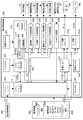
次に、図4を用いて、演出制御手段としての演出制御装置300の構成について説明する。
演出制御装置300は、主制御用マイコン(1stCPU)311と、該1stCPU311の制御下でもっぱら映像制御を行う映像制御用マイコン(2ndCPU)312と、該2ndCPU312からのコマンドやデータに従って表示装置41への映像表示のための画像処理を行うグラフィックプロセッサとしてのVDP(Video Display Processor
)313と、各種のメロディや効果音などをスピーカ19a,19bから再生させるため音の出力を制御する音源LSI314を備えている。
Next, the configuration of the
The
313 and a
上記主制御用マイコン(1stCPU)311と映像制御用マイコン(2ndCPU)312には、各CPUが実行するプログラムを格納したPROM(プログラマブルリードオンリメモリ)からなるプログラムROM321、322がそれぞれ接続され、VDP313にはキャラクタ画像や映像データ、コマンドリストが記憶された画像ROM323が接続され、音源LSI314には圧縮された音声データやフレーズ再生処理に必要なシーケンス、簡易アクセスのためのコマンド列等が記憶された音声ROM324が接続されている。
主制御用マイコン(1stCPU)311は、遊技用マイコン111からのコマンドを解析し、演出内容を決定して映像制御用マイコン312へ出力映像の内容を指示したり、音源LSI314への再生音の指示、装飾ランプの点灯、モータの駆動制御、演出時間の管理などの処理を実行する。主制御用マイコン(1stCPU)311と映像制御用マイコン(2ndCPU)312の作業領域を提供するRAMは、それぞれのチップ内部に設けられている。なお、作業領域を提供するRAMはチップの外部に設けるようにしてもよい。
The main control microcomputer (1st CPU) 311 and the video control microcomputer (2nd CPU) 312 are connected to program
The main control microcomputer (1st CPU) 311 analyzes the command from the
特に限定されるわけではないが、主制御用マイコン(1stCPU)311と映像制御用マイコン(2ndCPU)312との間、主制御用マイコン(1stCPU)311と音源LSI314との間は、それぞれシリアル方式でデータの送受信が行なわれ、映像制御用マイコン(2ndCPU)312との間、主制御用マイコン(1stCPU)311とVDP313との間は、パラレル方式でデータの送受信が行なわれるように構成されている。パラレル方式でデータを送受信することで、シリアルの場合よりも短時間にコマンドやデータを送信することができる。VDP313には、画像ROM323から読み出されたキャラクタなどの画像データを展開したり加工したりするのに使用される超高速なVRAM(ビデオRAM)305や、画像データを描画処理するための描画回路306、LVDS(小振幅信号伝送)方式で表示装置41へ送信する映像信号を生成する表示回路308などが設けられている。VDP313については後に詳しく説明する。
Although not particularly limited, the main control microcomputer (1stCPU) 311 and the video control microcomputer (2ndCPU) 312 and the main control microcomputer (1stCPU) 311 and the
VDP313から主制御用マイコン311へは表示装置41の映像と前面枠12や遊技盤30に設けられている装飾ランプの点灯を同期させるために垂直同期信号VSYNCが入力される。さらに、VDP313から映像制御用マイコン312へは、VRAMへの描画の終了等処理状況を知らせるため割込み信号INT0〜n及び映像制御用マイコン312からのコマンドやデータの受信待ちの状態にあることを知らせるためのウェイト信号WAITが入力される。また、映像制御用マイコン312から主制御用マイコン311へは、映像制御用マイコン312が正常に動作していることを知らせるとともにコマンドの送信タイミングを与える同期信号SYNCが入力される。主制御用マイコン311と音源LSI314との間は、ハンドシェイク方式でコマンドやデータの送受信を行うために、呼び掛け(コール)信号CTSと応答(レスポンス)信号RTSが交換される。
A vertical synchronization signal VSYNC is input from the
なお、映像制御用マイコン(2ndCPU)312には、主制御用マイコン(1stCPU)311よりも高速なつまり高価なCPUが使用されている。主制御用マイコン(1stCPU)311とは別に映像制御用マイコン(2ndCPU)312を設けて処理を分担させることによって、主制御用マイコン(1stCPU)311のみでは実現困難な大画面で動きの速い映像を表示装置41に表示させることが可能となるとともに、映像制御用マイコン(2ndCPU)312と同等な処理能力を有するCPUを2個使用する場合に比べてコストの上昇を抑制することができる。また、CPUを2つ設けることによって、2つのCPUの制御プログラムを別々に並行して開発することが可能となり、これによって新機種の開発期間を短縮することができる。
Note that the video control microcomputer (2ndCPU) 312 uses a CPU that is faster or more expensive than the main control microcomputer (1stCPU) 311. By providing a video control microcomputer (2ndCPU) 312 separately from the main control microcomputer (1stCPU) 311 and sharing the processing, it is possible to display a fast moving image on a large screen that is difficult to achieve with the main control microcomputer (1stCPU) 311 alone. It is possible to display on the
また、演出制御装置300には、遊技制御装置100から送信されてくる演出制御コマンドを受信するインタフェースチップ(コマンドI/F)331が設けられている。このコマンドI/F331を介して、遊技制御装置100から演出制御装置300へ送信された変動開始コマンド、客待ちデモコマンド、ファンファーレコマンド、確率情報コマンド、及びエラー指定コマンド等を、演出制御指令信号として受信する。遊技制御装置100の遊技用マイコン111はDC5Vで動作し、演出制御装置300の主制御用マイコン(1stCPU)311はDC3.3Vで動作するため、コマンドI/F331には信号のレベル変換の機能が設けられている。
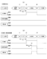
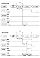
なお、本実施形態においては、演出制御コマンドは16ビットで構成されており、これ
を8ビットのデータバスとストローブ信号SSBTで送信するため、図23に示すように、16ビットの演出制御コマンドを8ビットの前半コマンド(MODE)と後半コマンド(ACTION)とに分けて、ストローブ信号SSBTを2度立ち上げることで送信し、受信側ではSSBの立ち上がりに同期してコマンドを取り込むようになっている。
In addition, the
In this embodiment, the effect control command is composed of 16 bits, and this is transmitted by an 8-bit data bus and a strobe signal SSBT. Therefore, as shown in FIG. Dividing into 8-bit first half command (MODE) and second half command (ACTION), the strobe signal SSBT is sent up by raising it twice, and the receiving side takes in the command in synchronization with the rise of SSB. .
また、演出制御装置300には、遊技盤30(センターケース40を含む)に設けられているLED(発光ダイオード)を有する盤装飾装置42を駆動制御する盤装飾LED制御回路332、前面枠12に設けられているLED(発光ダイオード)を有する枠装飾装置(例えば枠装飾装置18等)を駆動制御する枠装飾LED制御回路333、遊技盤30(センターケース40を含む)に設けられている盤演出装置(例えば表示装置41における演出表示と協働して演出効果を高める電動役物等)44を駆動制御する盤演出モータ/SOL制御回路334、前面枠12に設けられているLEDやモータ等の枠演出装置(例えば前述の光照射装置29のLEDや後述の振動装置のモータ等)45を駆動制御する枠演出モータ制御回路335が設けられている。なお、ランプやモータ及びソレノイドなどを駆動制御するこれらの制御回路332〜335は、アドレス/データバス304を介して主制御用マイコン(1stCPU)311と接続されている。
The
さらに、演出制御装置300には、前面枠12に設けられた入力操作部25の演出ボタン25aやセレクトボタン25bに内蔵されているスイッチ、上記盤演出装置44内のモータの初期位置を検出する演出モータスイッチのオン/オフ状態を検出して主制御用マイコン(1stCPU)311へ検出信号を入力するスイッチ入力回路336、前面枠12に設けられた上スピーカ19aを駆動するオーディオパワーアンプなどからなるアンプ回路337a、前面枠12に設けられた下スピーカ19bを駆動するアンプ回路337bが設けられている。
Further, the
電源装置400の通常電源部410は、上記のような構成を有する演出制御装置300やそれによって制御される電子部品に対して所望のレベルの直流電圧を供給するため、モータやソレノイドを駆動するためのDC32V、液晶パネルからなる表示装置41を駆動するためのDC12V、コマンドI/F331の電源電圧となるDC5Vの他に、LEDやスピーカを駆動するためのDC18Vやこれらの直流電圧の基準としたり電源モニタランプを点灯させるのに使用するNDC24Vの電圧を生成するように構成されている。さらに、主制御用マイコン(1stCPU)311や映像制御用マイコン(2ndCPU)312として、3.3Vあるいは1.2Vのような低電圧で動作するLSIを使用する場合には、DC5Vに基づいてDC3.3VやDC1.2Vを生成するためのDC−DCコンバータが演出制御装置300に設けられる。なお、DC−DCコンバータは通常電源部410に設けるようにしてもよい。
The normal
電源装置400の制御信号生成部430により生成されたリセット信号RSTは、主制御用マイコン311、映像制御用マイコン312、VDP313、音源LSI314、ランプやモータなどを駆動制御する制御回路332〜335、スピーカを駆動するアンプ回路337a、337bに供給され、これらをリセット状態にする。また、この実施形態においては、映像制御用マイコン312の有する汎用のポートを利用して、VDP313に対するリセット信号を生成して供給する機能を有するように構成されている。これにより、映像制御用マイコン312とVDP313の動作の連携性を向上させることができる。
The reset signal RST generated by the control
図13には、演出制御装置300を構成するグラフィックプロセッサとしての上記VDP313の内部構成を示す機能ブロック図が示されている。
VDP313は、映像制御用マイコン(2ndCPU)312との間でコマンドなどの送受信を行うCPUインタフェース301と、画像ROM323からのデータの受信を行うCGバスインタフェース302、DMA(ダイレクトメモリアクセス)制御で2ndC
PU312や画像ROM323と間のデータ転送を行うデータ転送回路303、画像ROM323から読み出された圧縮データを伸長するデコーダ304を備える。
FIG. 13 is a functional block diagram showing the internal configuration of the
The
A data transfer circuit 303 that transfers data between the
また、VDP313は、画像データの描画の際に使用する素材データを格納する画像RAM(VRAM CG)305、2ndCPU312から送られてきたコマンドもしくは画像ROM323から読み出されたコマンドリストに従って画像ROM323から読み出した画像データを予め設定した相対座標内で描画処理し描画データを生成するCPUなどからなる描画回路306、描画回路306によって生成された描画データを格納するフレームバッファとしての画像RAM(VRAM FB)307、該画像RAM307に格納された1画面分の描画データを表示データとして順次読み出してデジタル表示信号を表示装置41へ出力する表示回路308などを備える。
The
フレームバッファとしての画像RAM307は、本実施形態では表示装置41の2画面分の表示データを記憶可能な記憶容量を備えており、描画回路306が1フレーム(1画面)の表示データの描画を行っている間に、既に描画された他方のフレームの表示データを表示回路308によって読み出す処理を交互に繰り返すことで動画像を表示装置41に表示させるように構成されている。
従って、表示制御手段としてのVDP313(グラフィックプロセッサ)は、画像データを格納する画像データ記憶手段と、画像データ記憶手段から読み出した画像データを予め設定した相対座標内で描画処理し、描画データを生成する描画処理手段と、描画処理手段によって生成される描画データを格納するフレームバッファと、所定のフレーム更新タイミングで、前記フレームバッファに格納された前記描画データを読み出して、前記表示装置で表示可能な表示データを出力する表示データ出力手段とを備えることとなる。
なお、画像RAM307の記憶容量は2フレームの大きさに限定されるものでなく、1フレームでもよいし、3フレーム以上であっても良い。
In this embodiment, the image RAM 307 as a frame buffer has a storage capacity capable of storing display data for two screens of the
Accordingly, the VDP 313 (graphic processor) as the display control means generates image data by drawing the image data stored in the image data storage means and the image data read from the image data storage means within preset relative coordinates. A drawing processing unit that performs the processing, a frame buffer that stores drawing data generated by the drawing processing unit, and the drawing data stored in the frame buffer can be read at a predetermined frame update timing and displayed on the display device Display data output means for outputting the display data.
Note that the storage capacity of the image RAM 307 is not limited to the size of two frames, and may be one frame or three or more frames.
図6には、演出制御装置300を構成する上記音源LSI(サウンドIC)314の内部構成を示す機能ブロック図が示されている。
音源LSI(サウンドIC)314は、演出制御装置300全体を制御する主制御用マイコン(1stCPU)311との間でコマンドなどの送受信を行うCPUインタフェース341と、主制御用マイコン(1stCPU)311が遊技制御装置100から受信したコマンドに応じてフレーズの再生や音量設定、パン(各チャンネルの音の混合比率や出力比率等)の設定などの処理を音声ROM324に格納されているシーケスに従って順次実行するシーケンサ342、遊技制御装置100から送信された簡易アクセスコマンドを受信したことに応じて音声ROM324から該コマンド対応したコマンド列を読み出して実行する簡易アクセス回路343、音声ROM324から読み出された圧縮音声データを伸長するデコーダ344を備える。
FIG. 6 is a functional block diagram showing the internal configuration of the sound source LSI (sound IC) 314 that constitutes the
The sound source LSI (sound IC) 314 includes a CPU interface 341 that transmits and receives commands and the like to and from the main control microcomputer (1st CPU) 311 that controls the entire
さらに、音源LSI(サウンドIC)314は、該LSIに設けられている16チャンネルの単位音源のそれぞれについて音量を設定するチャンネルボリューム回路345、任意のチャンネルの音源同士を混合するチャンネルミックス回路346、各チャンネルの音源もしくは混合された合成音にエフェクト(音響効果)を与えるエフェクト回路347、16チャンネル全体での音量を調節するトータルボリューム回路348、調節された音源データをアナログ信号に変換して指定された出力端子へスピーカ駆動信号として出力する出力インタフェース349を備える。出力インタフェース349から出力されるスピーカ駆動信号は、本実施形態では、上スピーカ(左右)19a用の駆動信号R,Lと、下スピーカ19b用の駆動信号SUBである。
Furthermore, a sound source LSI (sound IC) 314 includes a channel volume circuit 345 for setting the volume for each of 16 channel unit sound sources provided in the LSI, a channel mix circuit 346 for mixing sound sources of arbitrary channels, An effect circuit 347 for applying an effect (sound effect) to the sound source of the channel or the mixed synthesized sound, a total volume circuit 348 for adjusting the volume of the entire 16 channels, and the adjusted sound source data converted into an analog signal and designated An output interface 349 that outputs a speaker drive signal to the output terminal is provided. In this embodiment, the speaker drive signals output from the output interface 349 are the drive signals R and L for the upper speaker (left and right) 19a and the drive signal SUB for the
次に、遊技制御装置100において行われる遊技制御について説明する。
遊技制御装置100の遊技用マイコン111のCPU111Aでは、普図始動ゲート3
4に備えられたゲートスイッチ34aからの遊技球の検出信号の入力に基づき、普図の当たり判定用乱数値を抽出してROM111Bに記憶されている判定値と比較し、普図変動表示ゲームの当たり外れを判定する処理を行う。そして、LED表示部53において、識別図柄を所定時間変動表示した後、停止表示する普図変動表示ゲームを表示する処理を行う。この普図変動表示ゲームの結果が当たりの場合は、LED表示部53に特別の結果態様を表示するとともに、普電ソレノイド37cを動作させ、普通変動入賞装置37の開閉部材37b、37bを所定時間(例えば、0.3秒間)上述のように開放する制御を行う。
Next, game control performed in the
In the
4, a random number value for hit determination of the common figure is extracted based on the input of the detection signal of the game ball from the
なお、本実施形態においては、普図変動表示ゲームの結果がはずれの場合は、LED表示部53に、はずれの結果態様を表示する制御を行う。
また、始動入賞口36に備えられた始動口1スイッチ36aからの遊技球の検出信号の入力に基づき始動入賞(始動記憶)を記憶し、この始動記憶に基づき、第1特図変動表示ゲームの大当たり判定用乱数値を抽出してROM111Bに記憶されている判定値と比較し、第1特図変動表示ゲームの当たり外れを判定する処理を行う。従って、CPU111Aは、乱数値の取得条件検出手段および乱数値取得手段として機能する。
In the present embodiment, when the result of the normal fluctuation display game is out of order, control is performed to display the outage result mode on the
Further, a start winning (starting memory) is stored based on an input of a detection signal of a game ball from a starting
また、普通変動入賞装置37に備えられた始動口2スイッチ37aからの遊技球の検出信号の入力に基づき始動記憶を記憶し、この始動記憶に基づき、第2特図変動表示ゲームの大当たり判定用乱数値を抽出してROM111Bに記憶されている判定値と比較し、第2特図変動表示ゲームの当たり外れを判定する処理を行う。
そして、遊技制御装置100のCPU111Aは、上記の第1特図変動表示ゲームや第2特図変動表示ゲームの判定結果を含む制御情報(演出制御コマンド)を、演出制御装置300に出力する。そして、一括表示装置50の特図1表示器や特図2表示器に、識別図柄を所定時間変動表示した後、停止表示する特図変動表示ゲームを表示する処理を行う。従って、CPU111Aは、乱数値を判定して遊技に係わる決定処理を行う遊技結果決定手段として機能する。
In addition, the start memory is stored based on the input of the detection signal of the game ball from the
Then, the
また、演出制御装置300は、遊技制御装置100からの制御信号に基づき、表示装置41で特図変動表示ゲームに対応した飾り特図変動表示ゲームを表示する処理を行う。
さらに、演出制御装置300では、遊技制御装置100からの制御信号に基づき、スピーカ19a,19bからの音の出力、各種LEDの発光を制御する処理等を行う。
そして、遊技制御装置100のCPU111Aは、特図変動表示ゲームの結果が当たりの場合は、特図1表示器や特図2表示器に特別結果態様を表示するとともに、特別遊技状態を発生させる処理を行う。
特別遊技状態を発生させる処理においては、CPU111Aは、例えば、大入賞口ソレノイド38bにより特別変動入賞装置38の開閉扉38cを開放させ、大入賞口内への遊技球の流入を可能とする制御を行う。
Further, the
Furthermore, in the
Then, when the result of the special figure variation display game is a win, the
In the process of generating the special game state, the
そして、大入賞口に所定個数(例えば、10個)の遊技球が入賞するか、大入賞口の開放から所定時間(例えば、25秒又は1秒)が経過するかの何れかの条件が達成されるまで大入賞口を開放することを1ラウンドとし、これを所定ラウンド回数(例えば、15回又は2回)継続する(繰り返す)制御(サイクル遊技)を行う。
また、特図変動表示ゲームの結果がはずれの場合は、特図1表示器や特図2表示器にはずれの結果態様を表示する制御を行う。
Then, a condition that either a predetermined number (for example, 10) of game balls wins the grand prize opening or a predetermined time (for example, 25 seconds or 1 second) elapses from the opening of the big prize opening is achieved. Opening the grand prize opening until one is made is defined as one round, and control (cycle game) is performed to continue (repeat) this for a predetermined number of rounds (for example, 15 times or 2 times).
In addition, when the result of the special figure variation display game is out of control, control is performed to display the result form of the deviation on the special figure 1 display or the special figure 2 display.
また、遊技制御装置100は、特図変動表示ゲームの結果態様に基づき、特別遊技状態の終了後に、遊技状態として確変状態を発生可能となっている。
この確変状態は、特図変動表示ゲームにて当り結果となる確率が、通常確率状態に比べて高い状態(高確率状態)である。また、第1特図変動表示ゲーム及び第2特図変動表示
ゲームのどちらの特図変動表示ゲームの結果態様に基づき確変状態となっても、第1特図変動表示ゲーム及び第2特図変動表示ゲームの両方が確変状態となる。
In addition, the
This probability variation state is a state (high probability state) in which the probability of a hit result in the special figure variation display game is higher than the normal probability state. In addition, the first special figure variation display game and the second special figure variation display game, regardless of which one of the first special figure variation display game and the second special figure variation display game results in a certain variation state. Both display games are in a probable state.
また、遊技制御装置100は、特図変動表示ゲームの結果態様に基づき、特別遊技状態の終了後に、遊技状態として時短状態を発生可能となっている。
この時短状態においては、普図変動表示ゲーム及び普通変動入賞装置37を時短動作状態とする制御を行う。具体的には、時短状態においては、上述の普図変動表示ゲームの実行時間が第1の変動表示時間よりも短い第2の変動表示時間となるように制御され(例えば、10秒が1秒)、これにより、単位時間当りの普通変動入賞装置37の開放回数が実質的に多くなるように制御される。
また、時短状態においては、普図変動表示ゲームが当り結果となって普通変動入賞装置37が開放される場合に、開放時間が通常状態の第1開放時間よりも長い第2開放時間となるように制御される(例えば、0.3秒が1.7秒)。また、時短状態においては、普図変動表示ゲームの1回の当り結果に対して、普通変動入賞装置37の開放回数が1回の第1開放回数ではなく、2回以上の複数回(例えば、3回)の第2開放回数に設定される。以下、かかる制御モードを普電サポートと称する。
In addition, the
In this time-short state, control is performed so that the normal-variation display game and the normal
Further, in the short time state, when the normal
なお、普図変動表示ゲームの実行時間を第2の変動表示時間(例えば、1秒)とする制御と、普通変動入賞装置37の開放態様を開放時間が第2開放時間(例えば、1.7秒)とし、且つ、普図変動表示ゲームの1回の当り結果に対する開放回数が第2開放回数(例えば、3回)とする制御は、何れか一方のみを行っても良いし、両方を行っても良い。また、時短動作状態においては、普図変動表示ゲームの当り結果となる確率が通常動作状態より高くなるように制御してもよい。
これにより、普通変動入賞装置37に遊技球が入賞し易くなり、第2特図変動表示ゲームの始動が容易となる。
なお、確変状態と普図変動表示ゲーム及び普通変動入賞装置37の時短動作状態は、それぞれ独立して発生可能であり、両方を同時に発生することも可能であるし、一方のみを発生させることも可能である。
It should be noted that the execution time of the normal variation display game is set to the second variation display time (for example, 1 second), and the release mode of the normal
As a result, the game ball can easily win the normal
In addition, the time variation operation state of the probability variation state, the normal variation display game, and the normal variation
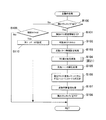
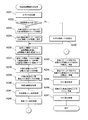
以下、上記のような遊技制御を実行する上記遊技制御装置100の遊技用マイクロコンピュータ(遊技用マイコン)111によって実行される処理について説明する。遊技用マイコン111による制御処理は、主に図14及び図15に示すメイン処理と、所定時間周期(例えば4msec)で行われる図16に示すタイマ割込み処理とからなる。
Hereinafter, processing executed by the gaming microcomputer (gaming microcomputer) 111 of the
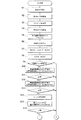
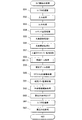
〔メイン処理〕
先ず、メイン処理について説明する。メイン処理は、電源が投入されることで開始される。このメイン処理においては、図14に示すように、まず、割込み禁止する処理(ステップS1)を行ってから、割込みが発生したときに実行するジャンプ先のベクタアドレスを設定する割込みベクタ設定処理(ステップS2)、割込みが発生したときにレジスタ等の値を退避する領域の先頭アドレスであるスタックポインタを設定するスタックポインタ設定処理(ステップS3)、割込み処理のモードを設定する割込みモード設定処理(ステップS4)を行う。
[Main processing]
First, the main process will be described. The main process is started when the power is turned on. In this main process, as shown in FIG. 14, first, an interrupt prohibition process (step S1) is performed, and then an interrupt vector setting process (step S1) for setting a jump destination vector address to be executed when an interrupt occurs. S2), a stack pointer setting process (step S3) for setting a stack pointer that is the start address of an area in which a value of a register or the like is saved when an interrupt occurs, and an interrupt mode setting process (step S4) for setting an interrupt processing mode. )I do.
次に、払出制御装置(払出基板)200のプログラムが正常に起動するのを待つため例えば4msecの時間待ちを行う(ステップS5)。これにより、電源投入の際に仮に遊技制御装置100が先に立ち上がって払出制御装置200が立ち上がる前にコマンドを払出制御装置200へ送ってしまい、払出制御装置200がコマンドを取りこぼすのを回避することができる。その後、RAMやEEPROM等の読出し書込み可能なRWM(リードライトメモリ:RAM111C)のアクセス許可をし、全出力ポートをオフ(出力が無
い状態)に設定する(ステップS6,S7)。また、シリアルポート((遊技用マイコン
111に予め搭載されているポート)この実施形態では、払出制御装置200や演出制御装置300とパラレル通信を行っているため使用しない)を使用しない状態に設定する処理を行う(ステップS8)。
Next, in order to wait for the program of the payout control apparatus (payout board) 200 to start up normally, for example, a time of 4 msec is waited (step S5). As a result, when the power is turned on, the
続いて、電源装置400内の初期化スイッチがオンしているか否か判定する(ステップS9)。ここで、初期化スイッチがオフ(ステップS9;No)と判定すると、RWM内の停電検査領域1の値が正常な停電検査領域チェックデータであるかをチェックし(ステップS10)、正常であれば(ステップS11;Yes)、RWM内の停電検査領域2の値が正常な停電検査領域チェックデータであるかをチェックする(ステップS12)。次に、停電検査領域2の値が正常であれば(ステップS13;Yes)、RWM内の所定領域のチェックサムを算出し(ステップS14)、算出されたチェックサムと電源断時のチェックサムを比較して(ステップS15)、一致するかを判定する(ステップS16)。そして、一致する場合(ステップS16;Yes)は、図15のステップS17へ移行し、停電から正常に復旧した場合の処理を行う。
Subsequently, it is determined whether or not the initialization switch in the
また、初期化スイッチがオン(ステップS9;Yes)と判定された場合や、停電検査領域のチェックデータが正常なデータでないと判定された場合(ステップS11;NoもしくはステップS13;No)、チェックサムが正常でない(ステップS16;No)と判定された場合は、図15のステップS24へ移行して初期化の処理を行う。 When the initialization switch is determined to be on (step S9; Yes), or when it is determined that the check data in the power failure inspection area is not normal data (step S11; No or step S13; No), the checksum Is determined to be not normal (step S16; No), the process proceeds to step S24 in FIG. 15 to perform initialization processing.
図15のステップS17では全ての停電検査領域をクリアし、チェックサム領域をクリアして(ステップS18)、エラーや不正監視に係る領域をリセットする(ステップS19)。次に、RWM内の遊技状態を記憶する領域を調べて遊技状態が高確率状態であるか否かを判定する(ステップS20)。ここで、高確率でない(ステップS20;No)と判定した場合は、ステップS21,S22をスキップしてステップS23へ移行する。 In step S17 of FIG. 15, all the power outage inspection areas are cleared, the checksum area is cleared (step S18), and the area related to error and fraud monitoring is reset (step S19). Next, an area for storing the gaming state in the RWM is examined to determine whether or not the gaming state is a high probability state (step S20). If it is determined that the probability is not high (step S20; No), steps S21 and S22 are skipped and the process proceeds to step S23.
また、ステップS20で高確率である(ステップS20;Yes)と判定した場合は、高確率報知フラグ領域にON情報をセーブし(ステップS21)、例えば一括表示装置50に設けられる高確率報知LED(エラー表示器)のON(点灯)データをセグメント領域にセーブする(ステップS22)。そして、後述の特図ゲーム処理を合理的に実行するために用意されている処理番号に対応する電源復旧時のコマンドを演出制御装置300へ送信する処理(ステップS23)を行ってステップS29へ進む。 If it is determined in step S20 that the probability is high (step S20; Yes), the ON information is saved in the high probability notification flag area (step S21), and the high probability notification LED (for example, provided in the batch display device 50) The ON (lighted) data of the error indicator is saved in the segment area (step S22). And the process (step S23) which transmits the command at the time of the power recovery corresponding to the process number prepared in order to rationally perform the below-mentioned special figure game process is performed (step S23), and it progresses to step S29 .
一方、ステップS9、S11、S13、S16からステップS24へジャンプした場合には、アクセス禁止領域より前の全作業領域をクリアし(ステップS24)、アクセス禁止領域より後の全スタック領域をクリアして(ステップS25)、初期化すべき領域に電源投入時の初期値をセーブする(ステップS26)。そして、RWMクリアに関する外部情報を出力する期間の時間値を設定し(ステップS27)、電源投入時のコマンドを演出制御装置300へ送信して(ステップS28)、ステップS29へ進む。ステップS29では、遊技用マイコン111(クロックジェネレータ)内のタイマ割込み信号及び乱数更新トリガ信号(CTC)を発生するCTC(Counter/Timer Circuit)回路を起動する処
理を行う。
On the other hand, when jumping from step S9, S11, S13, S16 to step S24, all work areas before the access prohibited area are cleared (step S24), and all stack areas after the access prohibited area are cleared. (Step S25), the initial value at power-on is saved in the area to be initialized (Step S26). And the time value of the period which outputs the external information regarding RWM clear is set (step S27), the command at the time of power-on is transmitted to the effect control apparatus 300 (step S28), and it progresses to step S29. In step S29, a process of starting a CTC (Counter / Timer Circuit) circuit that generates a timer interrupt signal and a random number update trigger signal (CTC) in the gaming microcomputer 111 (clock generator) is performed.
なお、CTC回路は、遊技用マイコン111内のクロックジェネレータに設けられている。クロックジェネレータは、水晶発振器113からの発振信号(原クロック信号)を分周する分周回路と、分周された信号に基づいてCPU111Aに対して所定周期(例えば、4ミリ秒)のタイマ割込み信号及び乱数生成回路へ供給する乱数更新のトリガを与える信号CTCを発生するCTC回路とを備えている。
The CTC circuit is provided in a clock generator in the
上記ステップS29のCTC起動処理の後は、乱数生成回路を起動設定する処理を行う
(ステップS30)。具体的には、乱数生成回路内の所定のレジスタ(CTC更新許可レジスタ)へ乱数生成回路を起動させるためのコード(指定値)の設定などがCPU111Aによって行われる。それから、電源投入時の乱数生成回路内の所定のレジスタ(ソフト乱数レジスタ1〜n)の値を、対応する各種初期値乱数(大当り図柄を決定する乱数(大当り図柄乱数1、大当り図柄乱数2)、普図の当たりを決定する乱数(当り乱数))の初期値(スタート値)としてRWMの所定領域にセーブしてから(ステップS31)、割込みを許可する(ステップS32)。本実施形態で使用するCPU111A内の乱数生成回路においては、電源投入毎にソフト乱数レジスタの初期値が変わるように構成されているため、この値を各種初期値乱数の初期値(スタート値)とすることで、ソフトウェアで生成される乱数の規則性を崩すことができ、遊技者による不正な乱数の取得を困難にすることができる。
After the CTC activation process in step S29, a process for activating and setting the random number generation circuit is performed (step S30). Specifically, the
続いて、各種初期値乱数の値を更新して乱数の規則性を崩すための初期値乱数更新処理(ステップS33)を行う。なお、本実施形態においては、特に限定されるわけではないが、大当り乱数は乱数生成回路において生成される乱数(大当り乱数)を使用して生成するように構成されている。つまり、大当り乱数はハードウェアで生成されるハード乱数であり、大当り図柄乱数、当り乱数はソフトウェアで生成されるソフト乱数である。 Subsequently, an initial value random number update process (step S33) is performed to update the values of various initial value random numbers to break the regularity of the random numbers. In the present embodiment, although not particularly limited, the big hit random number is configured to be generated using a random number (big hit random number) generated in a random number generation circuit. That is, the big hit random number is a hard random number generated by hardware, and the big hit symbol random number is a soft random number generated by software.
上記ステップS33の初期値乱数更新処理の後、電源装置400から入力されている停電監視信号をポート及びデータバスを介して読み込んでチェックする回数を設定し(ステップS34)、停電監視信号がONであるかの判定を行う(ステップS35)。停電監視信号がONでない場合(ステップS35;No)は、初期値乱数更新処理(ステップS33)に戻る。すなわち、停電が発生していない場合には、初期値乱数更新処理と停電監視信号のチェック(ループ処理)を繰り返し行う。初期値乱数更新処理(ステップS33)の前に割り込みを許可する(ステップS32)ことによって、初期値乱数更新処理中にタイマ割込みが発生すると割込み処理が優先して実行されるようになり、タイマ割込みが初期値乱数更新処理によって待たされることで割込み処理が圧迫されるのを回避することができる。
After the initial value random number update process in step S33, the number of times the power failure monitoring signal input from the
なお、上記ステップS33での初期値乱数更新処理は、メイン処理のほか、タイマ割込み処理の中においても初期値乱数更新処理を行う方法もあり、そのような方法を採用した場合には両方で初期値乱数更新処理が実行されるのを回避するため、メイン処理で初期値乱数更新処理を行う場合には割込みを禁止してから更新して割込みを解除する必要があるが、本実施形態のようにタイマ割込み処理の中での初期値乱数更新処理はせず、メイン処理内のみにした場合には初期値乱数更新処理の前に割込みを解除しても何ら問題はなく、それによってメイン処理が簡素化されるという利点がある。 Note that the initial value random number update process in step S33 includes a method of performing an initial value random number update process in the timer interrupt process in addition to the main process. In order to avoid execution of the value random number update process, when performing the initial value random number update process in the main process, it is necessary to disable the interrupt and then update to cancel the interrupt. If the initial value random number update process in the timer interrupt process is not performed in the main process and only the main process is performed, there is no problem even if the interrupt is canceled before the initial value random number update process. There is an advantage that it is simplified.
また、停電監視信号がONである場合(ステップS35;Yes)は、ステップS34で設定したチェック回数分停電監視信号のON状態が継続しているかを判定する(ステップS36)。そして、チェック回数分停電監視信号のON状態が継続していない場合(ステップS36;No)は、停電監視信号がONであるかの判定(ステップS35;Yes)に戻る。また、チェック回数分停電監視信号のON状態が継続している場合(ステップS36;Yes)、すなわち、停電が発生していると判定した場合は、一旦割込みを禁止する処理(ステップS37)、全出力ポートにOFFデータを出力する処理(ステップS38)を行う。 If the power failure monitoring signal is ON (step S35; Yes), it is determined whether or not the power failure monitoring signal is in the ON state for the number of checks set in step S34 (step S36). And when the ON state of the power failure monitoring signal is not continued for the number of checks (step S36; No), the process returns to the determination of whether the power failure monitoring signal is ON (step S35; Yes). Further, when the power failure monitoring signal is ON for the number of checks (step S36; Yes), that is, when it is determined that a power failure has occurred, processing for temporarily prohibiting interruption (step S37), all A process of outputting OFF data to the output port (step S38) is performed.
その後、停電復旧検査領域1に停電復旧検査領域チェックデータ1をセーブし(ステップS39)、停電復旧検査領域2に停電復旧検査領域チェックデータ2をセーブする(ステップS40)。さらに、RWMの電源遮断時のチェックサムを算出する処理(ステップS41)、チェックサムをセーブする処理(ステップS42)を行った後、RWMへのア
クセスを禁止する処理(ステップS43)を行ってから、遊技機の電源が遮断されるのを待つ。このように、停電復旧検査領域にチェックデータをセーブするとともに、電源遮断時のチェックサムを算出することで、電源の遮断の前にRWMに記憶されていた情報が正しくバックアップされているか否かを電源再投入時に判断することができる。
Thereafter, the power failure recovery inspection
〔タイマ割込み処理〕
次に、タイマ割込み処理について図16のフローチャートを用いて説明する。
図16に示すタイマ割込み処理は、クロックジェネレータ内のCTC回路で生成される周期的なタイマ割込み信号がCPU111Aに入力されることで開始される。
[Timer interrupt processing]
Next, timer interrupt processing will be described with reference to the flowchart of FIG.
The timer interrupt process shown in FIG. 16 is started when a periodic timer interrupt signal generated by the CTC circuit in the clock generator is input to the
タイマ割込み処理が開始されると、まず所定のレジスタに保持されている値をRWMに移すレジスタ退避の処理(ステップS51)を行う。なお、本実施形態において遊技用マイコンとして使用しているZ80系のマイコンでは、当該処理を表レジスタに保持されている値を裏レジスタに退避することで置き換えることができる。次に、各種センサ(始動口1スイッチ36a、始動口2スイッチ37a、普図のゲートスイッチ34a、カウントスイッチ38aなど)からの入力の取込み、即ち、各入力ポートの状態を読み込む入力処理(ステップS52)を行う。それから、各種処理でセットされた出力データに基づき、ソレノイド(大入賞口SOL38b、普電SOL37c)等のアクチュエータの駆動制御などを行うための出力処理(ステップS53)を行う。
When the timer interrupt process is started, a register saving process (step S51) is performed in which a value held in a predetermined register is first transferred to the RWM. In the Z80 microcomputer used as the gaming microcomputer in this embodiment, the processing can be replaced by saving the value held in the front register to the back register. Next, an input process (step S52) for taking in inputs from various sensors (start
次に、各種処理で送信バッファにセットされたコマンドを演出制御装置300や払出制御装置200等に出力するコマンド送信処理(ステップS54)、乱数更新処理1(ステップS55)、乱数更新処理2(ステップS56)を行う。その後、始動口1スイッチ36a、始動口2スイッチ37a、普図のゲートスイッチ34a、入賞口スイッチ35a…35n、カウントスイッチ38aから正常な信号の入力があるか否かの監視や、エラーの監視(前面枠やガラス枠が開放されていないかなど)を行う入賞口スイッチ/エラー監視処理(ステップS57)を行う。また、特図変動表示ゲームに関する処理を行う特図ゲーム処理(ステップS58)、普図変動表示ゲームに関する処理を行う普図ゲーム処理(ステップS59)を行う。
Next, a command transmission process (step S54), a random number update process 1 (step S55), and a random number update process 2 (step S56) is performed. Thereafter, it is monitored whether a normal signal is input from the
次に、遊技機10に設けられ、特図変動ゲームの表示や遊技に関する各種情報を表示するセグメントLEDを所望の内容を表示するように駆動するセグメントLED編集処理(ステップS60)、磁気センサスイッチ61や振動センサスイッチ62からの検出信号をチェックして異常がないか判定する磁石不正監視処理(ステップS61)を行う。それから、外部の各種装置に出力する信号を出力バッファにセットする外部情報編集処理(ステップS62)を行う。続いて、割込み要求をクリアして割込みの終了を宣言する処理(ステップS63)を行い、ステップS51で退避したレジスタのデータを復帰する処理(ステップS64)を行った後、割込みを許可する処理(ステップS65)を行って、タイマ割込み処理を終了する。
Next, a segment LED editing process (step S60), which is provided in the
〔特図ゲーム処理〕
次に、上述のタイマ割込み処理における特図ゲーム処理(ステップS58)の詳細について説明する。
特図ゲーム処理では、始動口1スイッチ36a及び始動口2スイッチ37aの入力の監視と、特図変動表示ゲームに関する処理全体の制御、特図の表示の設定を行う。
図17に示すように、特図ゲーム処理では、先ず、始動口1スイッチ36a及び始動口2スイッチ37aの入賞を監視する始動スイッチ監視処理(ステップA1)を行う。
始動口スイッチ監視処理では、始動入賞口36、第2始動入賞口をなす普通変動入賞装置37に遊技球の入賞があると、各種乱数(大当り乱数など)の抽出を行い、当該入賞に基づく特図変動表示ゲームの開始前の段階で入賞に基づく遊技結果を事前に判定する遊技
結果事前判定を行う。
[Special Figure Game Processing]
Next, details of the special game process (step S58) in the above-described timer interrupt process will be described.
In the special figure game process, the input of the
As shown in FIG. 17, in the special figure game process, first, a start switch monitoring process (step A1) for monitoring winnings of the
In the start port switch monitoring process, when a game ball is won in the normal
次に、カウントスイッチ監視処理(ステップA2)を行う。このカウントスイッチ監視処理では、特別変動入賞装置38内に設けられたカウントスイッチ38aのカウント数を監視する処理を行う。
次に、特図ゲーム処理タイマを更新(−1)して、当該ゲーム処理タイマがタイムアップしたか否かをチェックして(ステップA3)、特図ゲーム処理タイマがタイムアップした(ステップA4;Yes)と判定すると、特図ゲーム処理番号に対応する処理に分岐させるために参照する特図ゲームシーケンス分岐テーブルをレジスタに設定する処理(ステップA5)を行って、当該テーブルを用いて特図ゲーム処理番号に対応する処理の分岐先アドレスを取得する処理(ステップA6)を行う。
Next, a count switch monitoring process (step A2) is performed. In this count switch monitoring process, a process of monitoring the count number of the
Next, the special figure game process timer is updated (-1) to check whether or not the game process timer has expired (step A3), and the special figure game process timer has expired (step A4; If the determination is Yes), a special figure game sequence branch table to be referred to for branching to a process corresponding to the special figure game process number is set in the register (step A5), and the special figure game is used using the table. A process (step A6) of acquiring a branch destination address of the process corresponding to the process number is performed.
そして、分岐処理終了後のリターンアドレスをスタック領域に退避させる処理(ステップA7)を行った後、ゲーム処理番号に応じてゲーム分岐処理(ステップA8)を行う。
ステップA8にて、ゲーム処理番号が「0」の場合は、特図変動表示ゲームの変動開始を監視し、特図変動表示ゲームの変動開始の設定や演出の設定や、特図変動中処理を行うために必要な情報の設定等を行う特図普段処理(ステップA9)を行う。
Then, after performing the process of saving the return address after the branch process to the stack area (step A7), the game branch process (step A8) is performed according to the game process number.
If the game process number is “0” in step A8, the fluctuation start of the special figure fluctuation display game is monitored, the fluctuation start setting of the special figure fluctuation display game, the setting of the effect, and the special figure fluctuation processing are performed. A special figure routine process (step A9) for setting information necessary for the execution is performed.
また、ステップA8にて、ゲーム処理番号が「1」の場合は、特図の停止表示時間の設定や、特図表示中処理を行うために必要な情報の設定等を行う特図変動中処理(ステップA10)を行う。
さらに、ステップA8にて、ゲーム処理番号が「2」の場合は、特図変動表示ゲームの遊技結果が大当りであれば、大当りの種類(2R大当りor15R大当り)に応じたファンファーレコマンドの設定や、各大当り(2R大当りor15R大当り)の大入賞口開放パターンに応じたファンファーレ時間の設定や、ファンファーレ/インターバル中処理を行うために必要な情報の設定等を行う特図表示中処理(ステップA11)を行う。
If the game process number is “1” in step A8, the special figure changing process for setting the stop display time of the special figure and setting the information necessary for performing the special figure display process is performed. (Step A10) is performed.
Furthermore, if the game processing number is “2” in step A8, if the game result of the special figure variation display game is a big hit, a fanfare command setting corresponding to the type of big hit (2R big hit or 15R big hit) Special chart display processing (step A11) for setting the fanfare time according to the big winning opening opening pattern of each jackpot (2R jackpot or 15R jackpot), setting information necessary for performing the fanfare / interval processing, etc. Do.
また、ステップA8にて、ゲーム処理番号が「3」の場合は、大入賞口の開放時間の設定や開放回数の更新、大入賞口開放中処理を行うために必要な情報の設定等を行うファンファーレ/インターバル中処理(ステップA12)を行う。
また、ステップA8にて、ゲーム処理番号が「4」の場合は、大当りラウンドが最終ラウンドでなければインターバルコマンドを設定する一方で最終ラウンドであれば大当り終了画面のコマンドを設定する処理や、大入賞口残存球処理を行うために必要な情報の設定等を行う大入賞口開放中処理(ステップA13)を行う。
In step A8, when the game process number is “3”, setting of the opening time of the big prize opening, updating of the number of times of opening, setting of information necessary for performing the processing during opening of the big prize opening, etc. are performed. Processing during fanfare / interval (step A12) is performed.
In step A8, if the game process number is “4”, an interval command is set if the big hit round is not the final round, while a big hit end screen command is set if the big round is the final round, A large winning opening opening process (step A13) for setting information necessary for performing the winning opening remaining ball processing is performed.
また、ステップA8にて、ゲーム処理番号が「5」の場合は、大当りラウンドが最終ラウンドであれば大入賞口内にある残存球が排出されるための時間を設定する処理や、大当り終了処理を行うために必要な情報の設定等を行う大入賞口残存球処理(ステップA14)を行う。
また、ステップA8にて、ゲーム処理番号が「6」の場合は、特図普段処理(ステップA9)を行うために必要な情報の設定等を行う大当り終了処理(ステップA15)を行う。
If the game process number is “5” in step A8, if the big hit round is the final round, a process for setting a time for discharging the remaining balls in the big prize opening and a big hit end process are performed. A big winning opening remaining ball process (step A14) for setting information necessary for the execution is performed.
If the game process number is “6” in step A8, a big hit end process (step A15) for setting information necessary for performing the special figure routine process (step A9) is performed.
そして、特図1表示器51または特図2表示器52の変動を制御するためのテーブルを準備した後(ステップA16)、特図1表示器51または特図2表示器52に係る図柄変動制御処理(ステップA17)を行い、当該特図ゲーム処理を終了する。
一方、ステップA4にて、特図ゲーム処理タイマがタイムアップしていない(ステップA4;No)と判定すると、処理をステップA16に移行して、それ以降の処理を行い、当該特図ゲーム処理を終了する。
以上説明したように、本実施形態においては、遊技制御装置100が変動表示ゲーム実
行手段および特別遊技状態制御手段として機能する。
And after preparing the table for controlling the fluctuation | variation of the special figure 1
On the other hand, if it is determined in step A4 that the special figure game process timer has not expired (step A4; No), the process proceeds to step A16, the subsequent process is performed, and the special figure game process is performed. finish.
As described above, in the present embodiment, the
次に、上記演出制御装置300の主制御用マイコン(1stCPU)311によって実行される制御について説明する。
主制御用マイコン311による制御処理は、図18に示す1stメイン処理と、所定時間ごと(例えば2msecごと)に行われるコマンド受信割込み処理とからなる。1stメイン処理では、プログラム全体の制御を行うようになっている。
Next, the control executed by the main control microcomputer (1st CPU) 311 of the
The control process by the
〔1stメイン処理〕
図18に示すように、1stメイン処理においては、先ず、割込みを禁止する処理(ステップB1)を行ってから、RAMを0クリアする処理(ステップB2)を行い、1stCPU311の初期化処理(ステップB3)を行う。
次に、RAMに初期値を設定する処理(ステップB4)を行い、乱数初期化処理(ステップB5)を行う。その後、各種割込みのタイマを起動する処理(ステップB6)を行い、割込みを許可する(ステップB7)。その後、主制御用マイコン311は、メインループ処理ステップB8〜B18を行う。
[1st main processing]
As shown in FIG. 18, in the 1st main process, first, a process for prohibiting interruption (step B1) is performed, then a process for clearing the RAM to 0 (step B2) is performed, and an initialization process for the 1st CPU 311 (step B3). )I do.
Next, processing for setting an initial value in the RAM (step B4) is performed, and random number initialization processing (step B5) is performed. Thereafter, processing for starting various interrupt timers (step B6) is performed, and interrupts are permitted (step B7). Thereafter, the
このメインループ処理では、先ず、ウォッチドッグタイマ(WDT)をクリアする処理(ステップB8)を行う。そして、演出ボタンSW25aからの入力処理(ステップB9)を行い、遊技制御コマンド解析処理(ステップB10)を行う。
この遊技制御コマンド解析処理では、遊技制御装置100から送信される遊技に関するコマンドを正しく受信したかを判定し、正しく受信していた場合にはコマンドを確定する処理を行う。遊技制御装置100から送信される一つのコマンドは、第1コマンド(MODE)と、第2コマンド(ACTION)との一対のデータにより構成されている。
そして、受信した第1コマンド(MODE)と第2コマンド(ACTION)の組み合わせが矛盾しない場合(例えば、MODE→ACTIONの順に受信した場合)に正しくコマンドを受信したと判定し、第1コマンド(MODE)と第2コマンド(ACTION)の組み合わせが矛盾する場合(例えば、ACTION→ACTIONの順やMODE→MODE→MODEの順に受信した場合)にコマンドの受信が異常であると判定するようになっている。
In this main loop process, first, a process (step B8) for clearing the watchdog timer (WDT) is performed. Then, an input process from the effect button SW25a (step B9) is performed, and a game control command analysis process (step B10) is performed.
In this game control command analysis process, it is determined whether or not a command related to a game transmitted from the
Then, when the combination of the received first command (MODE) and the second command (ACTION) is not inconsistent (for example, when received in the order of MODE → ACTION), it is determined that the command is correctly received, and the first command (MODE) ) And the second command (ACTION) are inconsistent (for example, when received in the order of ACTION → ACTION or in the order of MODE → MODE → MODE), it is determined that the command reception is abnormal. .
続いて、テストモード処理(ステップB11)を行った後、特図変動表示ゲームに関する処理を行うシーン制御処理(ステップB12)を行う。
次いで、前面枠(内枠)12やガラス枠15の開放などのエラー発生の監視を行う遊技機エラー監視処理(ステップB13)、特図変動表示ゲームにおける演出に関する演出コマンド編集処理(ステップB14)、音声の出力に関する処理(スピーカ19a、19bの駆動処理)であるサウンド制御処理(ステップB15)、前面枠12に設けられた枠装飾装置18の制御に関する処理である装飾制御処理(ステップB16)、センターケース40に設けられた役物等を駆動させる盤演出モータ/SOL制御回路334の制御に関するモータ/SOL制御処理(ステップB17)、飾り特図変動表示ゲームの変動態様(変動パターン)等の詳細を決定する乱数を更新する乱数更新処理(ステップB18)を行い、ウォッチドッグタイマをクリアする処理(ステップB8)に戻る。
Subsequently, after performing a test mode process (step B11), a scene control process (step B12) for performing a process related to the special figure variation display game is performed.
Next, a gaming machine error monitoring process (step B13) for monitoring the occurrence of errors such as opening of the front frame (inner frame) 12 and the
〔1stシーン制御処理〕
図19には、図18に示した1stメイン処理における1stシーン制御処理(ステップB22)を示した。この1stシーン制御処理では、まず、テストモード中であるかを判定し(ステップB61)、テストモード中である場合(ステップB61;Yes)は、1stシーン制御処理を終了する。また、テストモード中でない場合(ステップB61;No)は、シーン変更コマンドを受信したか否かを判定する(ステップB62)。
[1st scene control processing]
FIG. 19 shows the 1st scene control process (step B22) in the 1st main process shown in FIG. In this 1st scene control process, first, it is determined whether or not the test mode is in effect (step B61). If the test mode is in effect (step B61; Yes), the 1st scene control process is terminated. When the test mode is not being executed (step B61; No), it is determined whether a scene change command has been received (step B62).
シーン変更コマンドは、遊技制御装置100から演出制御装置300に送信される遊技に関する各種のコマンドである。このシーン変更コマンドを受信した場合(ステップB62;Yes)は、更新する遊技状態(現在の遊技状態)を取得し(ステップB63)、有効なコマンドであるかを判定する(ステップB64)。有効なコマンドであるかの判定(ステップB64)では、受信したシーン変更コマンドが取得した現在の遊技状態に対して有効なものであるかを判定する。そして、有効なコマンドである場合(ステップB64;Yes)は、受信コマンドをセーブし(ステップB65)、演出リクエストフラグをセットして(ステップB66)、受信したコマンドのコマンド識別子による分岐処理(ステップB67)を行う。
The scene change commands are various commands relating to games transmitted from the
一方、シーン変更コマンドを受信していない場合(ステップB62;No)や、有効なコマンドでなかった場合(ステップB64;No)は、受信したコマンドのコマンド識別子による分岐処理(ステップB67)を行う。この場合、直近の有効であったコマンドの識別子による分岐を行う。 On the other hand, when the scene change command has not been received (step B62; No) or when it is not a valid command (step B64; No), branch processing (step B67) based on the command identifier of the received command is performed. In this case, a branch is performed based on the identifier of the command that was most recently valid.
コマンド識別子による分岐処理(ステップB67)では、受信したコマンドに基づき実行する処理を選択する。電源投入コマンドを受信した場合は電源投入時に必要な処理を行う電源投入処理(ステップB68)を行う。また、停電復旧コマンドを受信した場合は停電復旧時に必要な処理を行う停電復旧(客待ち以外)処理(ステップB69)を行う。また、客待ちデモコマンドを受信した場合は客待ちデモの表示に関する処理等を行う客待ち処理(ステップB70)を行う。 In the branch process based on the command identifier (step B67), a process to be executed based on the received command is selected. When a power-on command is received, a power-on process (step B68) is performed to perform a process necessary when the power is turned on. Further, when a power failure recovery command is received, a power failure recovery (other than customer waiting) processing (step B69) for performing processing necessary at the time of power failure recovery is performed. When a customer waiting demo command is received, a customer waiting process (step B70) for performing processing related to display of the customer waiting demo is performed.
また、変動パターンコマンドを受信した場合は飾り特図変動表示ゲームの実行に関する処理等を行う変動中処理(ステップB71)を行う。この変動中処理(ステップB71)では、飾り特図変動表示ゲームを行うために必要な情報の設定を行う。この飾り特図変動表示ゲームを行うために必要な情報の設定では、例えば、遊技制御装置100から送信された変動パターンコマンドに含まれる情報(大当りか否か、モード情報、変動パターン情報など)に基づき演出(変動パターンや変動時間など)の設定を行う。また、図柄停止コマンドを受信した場合は飾り特図変動表示ゲームにおける識別情報の変動表示を停止して結果態様を表示する処理である図柄停止処理(ステップB72)を行う。この図柄停止処理(ステップB72)では、飾り特図変動表示ゲームにおける結果の停止表示時間などの設定を行う。 In addition, when a variation pattern command is received, a variation processing (step B71) for performing processing related to the execution of the decoration special figure variation display game is performed. In the process during change (step B71), information necessary for playing the decoration special figure change display game is set. In the setting of information necessary for playing this decoration special figure variation display game, for example, information included in the variation pattern command transmitted from the game control device 100 (whether it is a big hit, mode information, variation pattern information, etc.) Based on this, production (variation pattern, variation time, etc.) is set. Further, when a symbol stop command is received, symbol stop processing (step B72), which is processing for stopping the variation display of the identification information in the decorative special symbol variation display game and displaying the result mode, is performed. In the symbol stop process (step B72), the result stop display time in the special symbol variation display game is set.
また、ファンファーレコマンドを受信した場合は特別遊技状態の開始に関する処理であるファンファーレ処理(ステップB73)を行う。また、大入開放n回目コマンドを受信した場合はラウンド遊技に関する処理であるラウンド中処理(ステップB74)を行う。また、インターバルコマンドを受信した場合はラウンド間のインターバルに関する処理であるインターバル処理(ステップB75)を行う。また、エンディングコマンドを受信した場合は特別遊技状態の終了に関する処理であるエンディング処理(ステップB76)を行う。 When a fanfare command is received, a fanfare process (step B73), which is a process related to the start of the special game state, is performed. In addition, when the large entry / release n-th command is received, an in-round process (step B74), which is a process related to a round game, is performed. When an interval command is received, an interval process (step B75) that is a process related to an interval between rounds is performed. When an ending command is received, an ending process (step B76), which is a process related to the end of the special gaming state, is performed.
コマンド識別子による分岐処理(ステップB67)により選択された上述の各処理を行った後、即座に映像に反映されないコマンドに基づく処理を行う。この処理として、まず、特図変動表示ゲームの停止図柄に関する情報を含む飾り特図コマンドに基づく処理を行う図柄コマンド受信処理(ステップB77)を行い、始動記憶の増減に関する情報を含む保留数コマンド(特図1保留数コマンド、特図2保留数コマンド)に基づく処理を行う保留数コマンド受信処理(ステップB78)を行う。 After performing each of the above-described processes selected by the branch process based on the command identifier (step B67), a process based on a command that is not immediately reflected in the video is performed. As this process, first, a symbol command reception process (step B77) for performing a process based on a decoration special command including information relating to a stop symbol of the special symbol variation display game is performed, and a pending number command including information relating to increase / decrease in the start memory ( A hold number command reception process (step B78) is performed for performing processing based on the special figure 1 hold number command and the special figure 2 hold number command.
さらに、始動記憶に基づく特図変動表示ゲームの結果等を当該特図変動表示ゲームの実行前に事前に判定する先読み処理の結果を含む先読みコマンド(始動口入賞演出コマンド
、始動口入賞演出図柄コマンド、転落情報コマンド)に基づく処理を行う先読みコマンド受信処理(ステップB79)を行う。その後、確率状態に関する情報を含む確率情報コマンド(転落情報コマンド、確率情報コマンド(低確率、高確率))に基づく処理を行う確率情報コマンド受信処理(ステップB80)を行う。
Further, a prefetch command (a start opening prize presentation command, a start opening prize presentation symbol command including a result of a prefetch process for determining the result of the special figure fluctuation display game based on the start memory in advance before the execution of the special figure fluctuation display game, etc. , Prefetch command reception processing (step B79) for performing processing based on the fall information command). Thereafter, a probability information command reception process (step B80) is performed in which a process based on a probability information command (falling information command, probability information command (low probability, high probability)) including information on the probability state is performed.
〔変動中処理〕
図20には、図19に示す1stシーン制御処理における変動中処理(ステップB71)を示した。この変動中処理では、まず、演出リクエストフラグがあるか否かを判定する(ステップB100)。演出リクエストフラグは、有効なコマンドを受信した場合に設定されるフラグであって、このフラグがある場合は受信したコマンドに基づく処理を行う。
[Fluctuation processing]
FIG. 20 shows the changing process (step B71) in the first scene control process shown in FIG. In this changing process, first, it is determined whether or not there is an effect request flag (step B100). The effect request flag is a flag that is set when a valid command is received. When there is this flag, processing based on the received command is performed.
この演出リクエストフラグがある場合(ステップB100;Yes)は、演出ボタン25の入力に関する情報であるPB情報をクリアし(ステップB101)、可動体リクエストセット処理(ステップB102)を行う。次に、飾り特図変動表示ゲームの実行態様を設定するための変動パターン情報設定処理(ステップB103)を行い、立体画像表示に関する後述の3D演出設定処理(ステップB104)を行う。
If there is an effect request flag (step B100; Yes), PB information that is information related to the input of the
その後、乱数シード初期化処理(ステップB105)を行って、設定された変動パターンに対応するシーンシーケンステーブルを設定する(ステップB106)。シーンシーケンステーブルは、飾り特図変動表示ゲームにおける変動表示の開始や停止、演出用キャラクタの表示等の各種表示の実行タイミングや時間を管理するテーブルである。シーンシーケンステーブルには、実行内容と時間とが定義された複数のシーンの実行順序が設定されており、このシーンシーケンステーブルに従い順次シーンを実行することで飾り特図変動表示ゲームが実行される。
その後、特定遊技状態とする回数等(普通変動入賞装置37を時短動作状態とする回数等)を管理する変動回数管理処理(ステップB107)を行い、演出リクエストフラグをクリアして(ステップB108)、変動中処理を終了する。
Thereafter, random number seed initialization processing (step B105) is performed, and a scene sequence table corresponding to the set variation pattern is set (step B106). The scene sequence table is a table for managing the execution timing and time of various displays such as the start and stop of the variable display and the display of the effect character in the decoration special figure variable display game. In the scene sequence table, the execution order of a plurality of scenes in which execution contents and time are defined is set, and the decorative special figure variation display game is executed by sequentially executing the scenes according to the scene sequence table.
Thereafter, a variation number management process (step B107) is performed to manage the number of times that the specific gaming state is set (the number of times the normal
一方、ステップB100で、演出リクエストフラグがない(=No)と判定した場合は、更新タイマの値が0であるかを判定する(ステップB109)。この場合、更新タイマはシーンシーケンステーブルに従い管理されるシーンの実行時間を計時しており、この更新タイマの値が0であるとは、実行されていたシーンが終了したことを示す。ステップB109で、更新タイマの値が0でない(=No)と判定した場合は、変動中処理を終了する。また、ステップB109で、更新タイマの値が0である(=Yes)と判定した場合は、次シーンデータの設定(ステップB110)を行い、変動中処理を終了する。これにより、新たなシーンが開始されるとともに更新タイマにシーンに応じた所定の値が設定される。 On the other hand, if it is determined in step B100 that there is no effect request flag (= No), it is determined whether the value of the update timer is 0 (step B109). In this case, the update timer measures the execution time of the scene managed according to the scene sequence table, and the value of this update timer being 0 indicates that the scene being executed has ended. If it is determined in step B109 that the value of the update timer is not 0 (= No), the changing process is terminated. If it is determined in step B109 that the value of the update timer is 0 (= Yes), the next scene data is set (step B110), and the changing process is terminated. As a result, a new scene is started and a predetermined value corresponding to the scene is set in the update timer.
〔3D演出設定処理〕
次に、図20の変動中処理のステップB104における3D演出設定処理の具体的な手順の一例を、図21に示すフローチャートを用いて説明する。
図21に示すように、この3D演出設定処理では、先ず、図20のステップB103で設定された変動パターンを確認する(ステップB141)。そして、開始する変動が3D演出を実行する変動であるか否かの判定(ステップB142)を行う。ここで、開始する変動が3D演出を実行する変動でない(No)と判定した場合は、当該3D演出設定処理を終了する。また、ステップB142で、開始する変動が3D演出を実行する変動である(Yes)と判定した場合は、ステップB143へ進んで、各種情報を確認してから、3D演出のパターンを抽選により選択する(ステップB144)。
[3D effect setting processing]
Next, an example of a specific procedure of the 3D effect setting process in step B104 of the changing process in FIG. 20 will be described with reference to the flowchart shown in FIG.
As shown in FIG. 21, in this 3D effect setting process, first, the variation pattern set in step B103 of FIG. 20 is confirmed (step B141). Then, it is determined whether or not the starting change is a change for executing the 3D effect (step B142). Here, when it is determined that the starting variation is not the variation for executing the 3D effect (No), the 3D effect setting process is ended. If it is determined in step B142 that the start variation is a variation for executing a 3D effect (Yes), the process proceeds to step B143, and after confirming various information, a 3D effect pattern is selected by lottery. (Step B144).
具体的には、図22(A)に示すような3D演出パターン選択テーブルと乱数を用いて
、選択を行う。そして、選択された3D演出を設定する(ステップB145)。図22(A)には一例として、5種類の演出パターン1〜5の中から、当該変動表示ゲームの結果が「はずれ」の場合と「大当り」の場合にそれぞれ所定の確率で選択する例が示されている。各演出パターンは、例えばキャラクタが異なるとか背景画像が異なるように設定される。
なお、5種類の演出パターンのうち「演出パターン5」は、「大当り」の場合にのみ出現するようにテーブルが設定されている。従って、遊技者は、この「演出パターン5」が出現した場合には、当該変動表示ゲームの結果が「大当り」になることを前もって知ることが可能となる。図22(B)には、各選択パターンの内容の例が示されている。この実施例では、演出パターン3〜5が、導光板を用いた演出を伴う3D演出である。
Specifically, the selection is performed using a 3D effect pattern selection table and a random number as shown in FIG. Then, the selected 3D effect is set (step B145). As an example, FIG. 22A shows an example of selecting from five types of
The table is set so that “
続いて、ステップB144で選択された3D演出が導光板(前面ガラス14a)を使用する演出であるか確認する(ステップB146)。そして、導光板を使用する演出であるか否かの判定(ステップB147)を行い、導光板を使用する演出でない(No)と判定した場合は、当該3D演出設定を終了する。また、ステップB147で、選択された3D演出が導光板を使用する演出である(Yes)と判定した場合は、ステップB148へ進んで、各種情報を確認する。続いて、導光板を使用する演出のパターンを抽選により選択する(ステップB149)。
Subsequently, it is confirmed whether the 3D effect selected in step B144 is an effect using the light guide plate (
具体的には、図23(A)に示すような導光板演出パターン選択テーブルと乱数を用いて、選択を行う。そして、選択された導光板演出を設定(ステップB150)し、3D演出設定処理を終了する。図23(A)には一例として、4種類のパターンa〜dの中から、ステップB144で選択された3D演出が、演出パターン3,4または5の場合に、それぞれ所定の確率で選択する例が示されている。図23(B)には、各導光板演出パターンの内容の具体例が示されている。ここでは、演出パターン5が最も期待度の高いリーチにおける演出パターンとして設定される。各パターンは、例えば導光板の照明時間の長さや全発光か一部発光かの差異が設けられ、区別される。ここで、「一部が発光」とは、ガラス枠の上部の光照射装置29内の複数のLEDランプのうち、一部が点灯されることを意味する。
Specifically, the selection is performed using a light guide plate effect pattern selection table and a random number as shown in FIG. Then, the selected light guide plate effect is set (step B150), and the 3D effect setting process is terminated. In FIG. 23A, as an example, when the 3D effect selected in step B144 is the
図23(A)より、本実施例においては、演出パターン5が選択された場合には、導光板演出パターンとして必ずパターンdが選択されるように設定されている。また、演出パターン4が選択された場合にも、導光板演出パターンとして10%の確率でパターンdが選択されるように設定されている。従って、この「演出パターン5」が選択された場合には、遊技者は、導光板演出パターンとして期待度の高いパターンdを楽しむことができる。また、「演出パターン4」が選択された場合にも、10%の確率でパターンdの導光板演出が実行されるため、この演出を楽しむことができるとともに、パターンdの導光板演出が実行されても外れの場合があるので、遊技者にはらはらどきどき感を与えることができる。
As shown in FIG. 23A, in the present embodiment, when the
次に、図24及び図25を用いて、表示装置41における3D画像による演出表示の例および該3D演出と連携させて導光板において行う演出表示の具体的な例について説明する。
この実施例においては、図24(a)のように変動表示ゲームにおいてリーチが発生し、図21に示すステップB144で、3D演出を伴う演出パターンが選択された場合、図24(b)のように、表示装置41の画面に3D画像のキャラクタ3DCを表示させる。そして、図25(c)のように、このキャラクタ3DCが手前に移動してガラスを叩く、あるいはぶつかるような動画を表示装置41において表示する。
Next, with reference to FIG. 24 and FIG. 25, an example of effect display using a 3D image on the
In this embodiment, as shown in FIG. 24A, when reach occurs in the variable display game as shown in FIG. 24A, and an effect pattern with a 3D effect is selected in step B144 shown in FIG. Then, the 3D character 3DC is displayed on the screen of the
その後、ガラス枠14の光照射装置29のLEDを発光させることで、図25(d)の
ように、表示装置41の前方の導光板(前面ガラス14a)において、導光板に形成されている模様を光らせる。この実施例では、導光板(前面ガラス14a)に「カミナリ」のような模様(G1,G2)が形成されている。そのため、恰もガラスにヒビが入ったかのようなイメージ表示を行うことができ、3D画像表示との連携で従来の遊技機の表示装置にはない、インパクトの大きな演出表示を実現することができる。
Thereafter, the LED of the
図26には、上記のような表示装置41における3D画像表示と導光板における表示とを連携させて演出を行う場合の制御タイミングの一例が示されている。このうち、(A)は3D画像表示のみの場合、(B)は3D画像表示と導光板における表示とを連携させる場合のものである。
この実施例においては、図26(B)に示すように、タイミングt1でリーチが発生して所定時間T1経過すると、3D画像表示が開始される(タイミングt2)。そして、さらに所定時間T2経過すると、導光板による表示が開始される(タイミングt3)。その後、3D画像表示と導光板における表示とが同時に終了し、リーチが発展するような演出が実行される。
FIG. 26 shows an example of the control timing when the 3D image display on the
In this embodiment, as shown in FIG. 26B, when a reach occurs at timing t1 and a predetermined time T1 elapses, 3D image display is started (timing t2). Then, when the predetermined time T2 further elapses, display by the light guide plate is started (timing t3). Thereafter, the 3D image display and the display on the light guide plate are finished at the same time, and an effect that the reach is developed is executed.
上記のような演出を行うことにより、当該変動表示ゲームの結果に対する遊技者の期待感を高めるとともに、従来にないインパクトの大きな演出が行われることで、遊技の興趣が向上されるようになる。なお、実施例においては、表示装置41による3D画像表示による演出、または3D画像表示と導光板による表示とを組み合わせた演出を行うようにしているが、導光板による表示のみによる演出を行うようにしてもよい。
By performing the effects as described above, the player's expectation with respect to the result of the variable display game is enhanced, and an effect with an unprecedented impact is performed, so that the interest of the game is improved. In the embodiment, an effect by 3D image display by the
(第2実施例)
次に、本発明の第2実施例について説明する。
第2の実施例は、図27に示すように、前面枠15を構成するベースプレート15b(図3参照)の下部にバイブレータ(振動装置)46を設け、表示装置41と導光板による表示と連携して動作させることで演出効果を高めることができるようにしたものである。なお、図27(B)は、図27(A)の一点鎖線Bで囲まれた部位を拡大して示したものである。バイブレータ46は、携帯電話機で使用されているものなど公知のものを利用できるので、具体例については説明を省略する。
(Second embodiment)
Next, a second embodiment of the present invention will be described.
In the second embodiment, as shown in FIG. 27, a vibrator (vibration device) 46 is provided below the
バイブレータ46を設ける位置は、ベースプレート15bに限定されず、上皿21や下皿23、操作ボタン25内部等であってもよい。また、バイブレータ46とガラス枠14に保持された前面ガラス14aとの間に振動を伝える振動伝達部材を設けて、前面ガラス14aを振動させるように構成してもよい。そして、その場合、バイブレータ46を、緩衝材となる弾性パッドを介してベースプレート15bに固定することで、ベースプレート15bに振動があまり伝わらないように構成するのが望ましい。
さらに、ベースプレート15bにバイブレータ46を設けた場合、その振動がガラス枠14に伝わり、遊技領域32に面した後方のガラス14bが振動して遊技領域32を流下する遊技球に影響を与えるのを防止するため、図28(B)に示すように、ガラス枠14に保持されている前面ガラス14aと後方のガラス14bとの間に、振動を吸収する例えばゴムのような振動吸収部材47を介在させるように構成してもよい。この場合、振動吸収部材47はガラスの周縁部等遊技機の前方から視認できない位置に配置するのが望ましい。
The position where the
Further, when the
また、普図始動ゲート34など遊技盤30の前面に配設されている入賞装置がある場合には、入賞装置の近傍に振動吸収部材47を介在させてもよい。そして、前方から見える位置に設ける場合にも、入賞口への打球の入賞の様子を見えなくするような位置から外れた部位であって、入賞装置と重なる位置に振動吸収部材47を配設するようにしてもよい。入賞装置と重なる位置であれば、入賞装置と同一色彩や模様をつけることで振動吸収部
材47があることを目立たなくすることができるとともに、入賞口への打球の入賞の様子を見えなくなるのを回避することができる。
In addition, when there is a winning device arranged on the front surface of the
次に、図29を用いて、表示装置41における3D画像による演出表示の例および該3D演出と連携させて導光板において行う演出表示の具体的な例について説明する。なお、図29は第1の実施例における図25に代わるものであり、図29の演出を行う前に、図24の演出が行われる。
すなわち、この実施例においては、図24(a)のように変動表示ゲームにおいてリーチが発生し、3D演出を伴う演出パターンが選択された場合に、図24(b)のように、表示装置41の画面に3D画像のキャラクタ3DCを表示させる。そして、その後、図29(e)のように、このキャラクタ3DCが手前に移動してガラスを叩くあるいはぶつかるような動画を表示装置41において表示する。これとともに、この実施例では、バイブレータ46を軽く振動させる。これにより、バイブレータ46の振動が前面ガラス14aに伝わってガラスを振動させる。このとき、ガラスが振動していることを遊技者に報知する表示を行うようにしてもよい。
Next, an example of effect display using a 3D image on the
That is, in this embodiment, when a reach occurs in the variable display game as shown in FIG. 24A and an effect pattern with a 3D effect is selected, as shown in FIG. The 3D character 3DC is displayed on the screen. Then, as shown in FIG. 29 (e), a moving image in which the character 3DC moves forward and hits or hits the glass is displayed on the
その後、ガラス枠14の光照射装置29のLEDを発光させることで、図25(f)のように、表示装置41の前方の導光板(前面ガラス14a)において、導光板に形成されている模様を光らせる。また、同時に、バイブレータ46の振動を強くする。すると、導光板に「カミナリ」のような模様(G1,G2)が形成されているため、恰もガラスにヒビが入ったかのようなイメージ表示を行うことができる。また、前面ガラス14aが振動することで表面の模様も揺れるため、遊技者はガラス14aが振動していることを認知することができ、より一層臨場感のある3D表示演出を実現することができる。
Thereafter, the LED of the
なお、近年、遊技者による不正を検出するため、振動センサを設けた遊技機が提供されているが、そのような振動センサを備えた遊技機においては、振動センサが誤ってバイブレータ46による振動を不正行為もしくは異常による振動として検出しないように、2つの振動を区別できるようなセンサを取り付けるか、バイブレータ46が振動している間の振動センサからの検出信号は不正もしくは異常と判定しないように制御装置のプログラムを作成するとよい。
In recent years, in order to detect fraud by a player, a gaming machine provided with a vibration sensor is provided. However, in a gaming machine equipped with such a vibration sensor, the vibration sensor erroneously vibrates by the
図30には、上記のような表示装置41における3D画像表示や導光板における表示との連携による演出に、バイブレータ46が振動を加えた演出を行う場合のタイミングの例が示されている。このうち、(A)は3D画像表示にバイブレータ46が振動を加えた演出を行う場合、(B)は3D画像表示に導光板における表示を連携させ、さらにバイブレータ46が振動を加えた演出を行う場合のものである。
FIG. 30 shows an example of timing when the
図30(A)の制御においては、タイミングt1でリーチが発生して所定時間T1経過すると、3D画像表示が開始されるとともにバイブレータ46が弱く振動される(タイミングt2)。
一方、図30(B)の制御においては、タイミングt1でリーチが発生して所定時間T1経過すると、3D画像表示が開始されるとともにバイブレータ46が弱く振動される(タイミングt2)。そして、さらに所定時間T2経過すると、導光板による表示が開始されるとともにバイブレータ46が強く振動される(タイミングt3)。その後、3D画像表示と導光板における表示とが同時に終了し、リーチが発展するような演出が実行される。
In the control of FIG. 30A, when a reach occurs at timing t1 and a predetermined time T1 elapses, 3D image display is started and the
On the other hand, in the control of FIG. 30B, when a reach occurs at timing t1 and a predetermined time T1 elapses, 3D image display is started and the
以上の説明から、上記実施例には、遊技盤の前方に配設される透明部材を保持する透明部材保持枠と、前記透明部材を通して視認可能で、遊技の進行に関連する演出表示として立体画像を表示可能な表示装置と、前記表示装置による演出表示を補助する演出装置と、
前記表示装置及び前記演出装置を制御する演出制御手段と、を備えた遊技機において、
前記演出装置は、前記透明部材保持枠に設けられ、前記透明部材もしくは透明部材保持枠を振動させる振動装置を含み、前記演出制御手段は、前記表示装置に前記立体画像を前記透明部材側に飛び出すように表示させ、前記表示装置に、前記立体画像を表示させることに関連して、前記振動装置によって前記透明部材もしくは透明部材保持枠を振動させるようにした発明が含まれることが分かる。
From the above description, in the above-described embodiment, the transparent member holding frame that holds the transparent member disposed in front of the game board, and the stereoscopic image that is visible through the transparent member and that is an effect display related to the progress of the game. A display device capable of displaying the effect, an effect device for assisting effect display by the display device,
In a gaming machine provided with an effect control means for controlling the display device and the effect device,
The effect device includes a vibration device that is provided on the transparent member holding frame and vibrates the transparent member or the transparent member holding frame, and the effect control unit projects the stereoscopic image to the transparent member side on the display device. It is understood that the invention includes the invention in which the transparent member or the transparent member holding frame is vibrated by the vibration device in connection with displaying the stereoscopic image on the display device.
そして、かかる発明によれば、立体動画像を表示する場合に、立体動画像の動作と関連して透明部材保持枠が振動するので、立体動画像および該画像と連携した振動による演出を、遊技者の視覚のみならず触覚に訴えることができる体感的な演出として実現することができる。特に、立体動画像は透明部材(保持枠)側に飛び出すように表示させるので、立体動画像の内容と、透明部材もしくは透明部材保持枠の振動との関連性を持たせることが容易であり、例えば、立体動画像が透明部材に触れるもしくは当たるような動作をする表示をさせ、その表示に合わせて振動を発生させることによって、遊技者に与えるインパクトを大きし遊技の興趣を高めることができる。 According to this invention, when a stereoscopic moving image is displayed, the transparent member holding frame vibrates in association with the operation of the stereoscopic moving image. It can be realized as a direct experience that can appeal to the tactile sense as well as the visual sense of the person. In particular, since the stereoscopic moving image is displayed so as to pop out on the transparent member (holding frame) side, it is easy to have a relationship between the content of the stereoscopic moving image and the vibration of the transparent member or the transparent member holding frame, For example, by causing a display in which a stereoscopic moving image touches or hits a transparent member and generating vibration in accordance with the display, it is possible to increase the impact on the player and enhance the interest of the game.
図31には、第2の実施例の変形例が示されている。
この変形例は、バイブレータ46を振動させるときに、振動していることを遊技者に報知するための報知手段を設けたものである。具体的には、図31のように、前面枠15を構成するベースプレート15b(図3参照)の下部左隅に揺動装置48を設けるとともに、該揺動装置48の振動杆48aの先端に前面パネル15aの一部を構成する装飾部材15dを結合したものである。装飾部材15dは独立した部品として形成されている。この変形例においては、前面枠15に振動を与えるバイブレータ46を振動させる際に、揺動装置48を作動させるように制御する。
FIG. 31 shows a modification of the second embodiment.
In this modification, when the
これにより、揺動装置48を作動させると装飾部材15dが揺動して遊技者が視覚により振動状態を認知させることができる。なお、独立した装飾部材15dを設ける代わりに、揺動装置48を設けた位置に対応して前飾りパネル15aの一部を透明もしくは半透明とし、揺動装置48の振動杆48aの先端にLEDランプを取り付けて、LEDランプを揺動させることで遊技者が視覚により振動状態を認知させることができるように構成してもよい。さらに、図31において、揺動装置48を設ける代わりに、図27(B)の振動装置46から図31の装飾部材15dに振動を伝達する振動伝達部材を設けるように構成してもよい。
Thus, when the
以上の説明から、上記実施例には、前記演出制御手段は、前記振動装置によって前記透明部材もしくは透明部材保持枠が振動していることを遊技者に報知する報知手段を備えるようにした発明が含まれることが分かる。
そして、かかる発明によれば、透明部材もしくは透明部材保持枠に振動が発生していることが遊技者に報知されるので、立体動画像による表示内容に関連して振動が発生していることを遊技者が認識しやすい演出を実行でき、振動を体感するために透明部材保持枠に触れるなど遊技者の好奇心を誘起することができ、演出を体感的に楽しむことができる。
From the above description, in the above embodiment, the effect control means includes an informing means for notifying a player that the transparent member or the transparent member holding frame is vibrating by the vibration device. It is understood that it is included.
And according to this invention, since the player is notified that the vibration is generated in the transparent member or the transparent member holding frame, the vibration is generated in relation to the display content by the stereoscopic moving image. An effect that the player can easily recognize can be executed, and the player's curiosity can be induced such as touching the transparent member holding frame in order to experience vibrations, so that the effect can be enjoyed physically.
また、上記実施例には、前記演出装置は、前記表示装置の前面に重なって配設され常態において透明な表示部を有する前面表示装置を含み、前記前面表示装置は、前記表示部を通して前記表示装置における演出表示を視認可能に構成され、前記表示部に、前記表示装置における演出表示を補助する画像を表示し、前記演出制御手段は、前記表示装置に、前記立体画像として立体動画像を表示させることに関連して、前記前面表示装置に前記演出表示を補助する画像を表示させるようにした発明が含まれる。
そして、かかる発明によれば、表示装置の前面側に前面表示装置が配設されているので、表示装置により立体画像を表示する場合に、遊技機の前方からは前面表示装置における
表示画像及び表示装置における立体動画像が重なった状態で視認可能となり、それぞれの装置による表示の組み合わせに応じて従来にない斬新な表示が実行されることとなり、表示のインパクトを高め、遊技の興趣を高めることができる。
Further, in the above embodiment, the rendering device includes a front display device that is disposed to overlap the front surface of the display device and has a transparent display portion in a normal state, and the front display device displays the display through the display portion. An effect display on the device is configured to be visible, an image assisting the effect display on the display device is displayed on the display unit, and the effect control means displays a stereoscopic moving image as the stereoscopic image on the display device. In relation to this, an invention in which an image assisting the effect display is displayed on the front display device is included.
According to this invention, since the front display device is disposed on the front side of the display device, when displaying a stereoscopic image by the display device, the display image and display on the front display device are displayed from the front of the gaming machine. It is possible to visually recognize the three-dimensional moving images on the devices in an overlapping state, and according to the combination of the displays by the respective devices, a novel display that is not conventional is executed, thereby increasing the impact of the display and enhancing the interest of the game. it can.
さらに、上記実施例には、前記演出制御手段は、前記表示装置に立体動画像を表示させるとともに、前記振動装置によって前記透明部材もしくは透明部材保持枠を振動させ、その後に前記前面表示装置に前記演出表示を補助する画像を表示させる第1演出態様を実行制御可能な発明が含まれる。
そして、かかる発明によれば、表示装置による立体動画像と、振動装置による振動と、前面表示装置による表示が一連の流れで行われるので、従来にない体感的な演出を実現し、該演出によって遊技者に与えるインパクトを大きくし、遊技の興趣を高めることができる。
特に、立体動画像の表示及び振動実施の後に演出表示を補助する画像が表示されるので、表示装置により表示される画像が奥から手前に移動して来て前面表示装置による表示画像と連携するような演出を実行することで、遊技者に演出内容の進行(ストーリー)を把握させ易くなる。
Furthermore, in the above embodiment, the effect control means causes the display device to display a stereoscopic moving image, vibrates the transparent member or the transparent member holding frame by the vibration device, and then causes the front display device to perform the operation. An invention capable of controlling execution of the first effect mode in which an image for assisting effect display is displayed is included.
And according to this invention, since the three-dimensional moving image by the display device, the vibration by the vibration device, and the display by the front display device are performed in a series of flows, an unprecedented bodily effect is realized, The impact on the player can be increased and the interest of the game can be enhanced.
In particular, since an image for assisting the effect display is displayed after the display of the three-dimensional moving image and the execution of vibration, the image displayed by the display device moves from the back to the front and cooperates with the display image by the front display device. By executing such an effect, it becomes easier for the player to grasp the progress (story) of the effect content.
また、上記実施例には、前記演出制御手段は、前記表示装置に、立体動画像による演出を表示させ、前記振動装置による振動及び前記前面表示装置による画像を表示させない第2演出態様と、前記表示装置に立体動画像による演出を表示させるとともに、前記振動装置によって前記透明部材もしくは透明部材保持枠を振動させ、前記前面表示装置による画像を表示させない第3演出態様と、を実行制御可能であるようにした発明が含まれる。
そして、かかる発明によれば、立体動画像が表示される第2演出態様と、立体動画像が表示され透明部材もしくは透明部材保持枠が振動する第3演出態様と、立体動画像が表示され透明部材もしくは透明部材保持枠が振動した後に前面表示装置に演出表示を補助する画像を表示させる第1演出態様があるため、遊技者は演出がどこまで進行するか期待を持って楽しむことができる。
Further, in the above-described embodiment, the effect control means causes the display device to display an effect due to a three-dimensional moving image, and does not display the vibration due to the vibration device and the image due to the front display device, It is possible to display an effect by a stereoscopic moving image on the display device, and to control the execution of a third effect mode in which the transparent member or the transparent member holding frame is vibrated by the vibration device and no image is displayed by the front display device. Such an invention is included.
And according to this invention, the 2nd production mode in which a 3D moving picture is displayed, the 3rd production mode in which a 3D moving picture is displayed and a transparent member or a transparent member holding frame vibrates, and a 3D moving picture are displayed and are transparent Since there is a first effect mode in which an image for assisting effect display is displayed on the front display device after the member or the transparent member holding frame vibrates, the player can enjoy with expectation how far the effect will progress.
さらに、上記実施例には、前記遊技盤に設けられた始動入賞領域への遊技球の入賞に基づき、前記表示装置において識別情報を変動表示する変動表示ゲームを実行する変動表示ゲーム実行手段と、前記変動表示ゲームの結果が予め定めた特別結果となった場合に、遊技者にとって有利な特別遊技状態を発生させる特別遊技状態制御手段と、を備え、前記演出制御手段は、前記特別結果が導出されることに関連して、前記第1演出態様、前記第2演出態様又は前記第3演出態様のいずれかを選択するようにした発明が含まれることが分かる。
そして、かかる発明によれば、大当りの発生と演出態様の選択に関連性があり、各演出態様が導出されたときに遊技者に対してそれぞれ異なる大当りへの期待感を与えることができる。
Furthermore, in the above embodiment, based on the winning of the game ball in the start winning area provided in the game board, a variable display game executing means for executing a variable display game for variable display of identification information on the display device, Special game state control means for generating a special game state advantageous to the player when the result of the variable display game becomes a predetermined special result, and the effect control means derives the special result. In connection with being done, it turns out that the invention made to select either the said 1st production | presentation aspect, the said 2nd production | presentation aspect, or the said 3rd production | presentation aspect is contained.
According to this invention, there is a relation between the occurrence of the big hit and the selection of the production mode, and when each production mode is derived, it is possible to give the player a sense of expectation for different big hits.
(第3実施例)
次に、本発明の第3実施例について説明する。
第3実施例は、いわゆる先読み演出において3D画像表示と導光板による表示とを組み合わせた演出を行うようにしたものである。
図32には、先読み演出を実現する場合に、遊技制御装置100において実行される特図保留情報判定処理の手順の一例が示されている。なお、この特図保留情報判定処理は、始動記憶に基づく特図変動表示ゲームの開始タイミングより前に、当該始動記憶に対応した結果関連情報の判定を行う処理であり、図17に示す特図ゲーム処理のステップA1の始動口スイッチ監視処理の中で実行される。
(Third embodiment)
Next, a third embodiment of the present invention will be described.
In the third embodiment, a so-called pre-reading effect is combined with a 3D image display and a light guide plate display.
FIG. 32 shows an example of the procedure of the special figure hold information determination process executed in the
特図保留情報判定処理においては、図32に示すように、先ず、発生した始動入力に応
じて取得した大当り乱数値に基づいて、当該始動入賞により実行される変動表示ゲームが大当りであるか否かを判定する処理(ステップA231)を行う。そして、判定結果が大当り(ステップA232;Yes)の場合には、ステップA233へ進んで、始動口1スイッチ36a及び始動口2スイッチ37aのうち、監視対象の始動口スイッチに対応する大当り図柄乱数チェックテーブルを設定する(ステップA233)。続いて、大当り図柄乱数をチェックして対応する大当り情報テーブルを取得し、設定する(ステップA234)。
In the special figure hold information determination process, as shown in FIG. 32, first, based on the jackpot random value acquired according to the generated start input, whether or not the variable display game executed by the start winning is a big hit. The process (step A231) which determines is performed. If the determination result is a big hit (step A232; Yes), the process proceeds to step A233 to check the big hit symbol random number corresponding to the monitored start port switch among the
一方、ステップA232における判定結果が大当りでない(ステップA232;No)と判定すると、ステップA235へ移行してはずれ情報テーブルを設定する。
それから、ステップA236へ進み、ステップA234またはステップA235で設定した情報テーブルから図柄情報を取得し、作業用のRAM内の図柄情報領域にセーブする。続いて、ステップA234またはステップA235で設定した情報テーブルから始動口始動口入賞演出図柄コマンド(図33参照)を取得し、作業用のRAM内の入賞演出図柄コマンド領域にセーブする(ステップA237)。
On the other hand, if it is determined that the determination result in step A232 is not a big hit (step A232; No), the process proceeds to step A235 to set a deviation information table.
Then, the process proceeds to step A236, where symbol information is acquired from the information table set in step A234 or step A235, and saved in the symbol information area in the working RAM. Subsequently, the start opening start opening winning effect symbol command (see FIG. 33) is acquired from the information table set in step A234 or step A235, and saved in the winning effect symbol command area in the working RAM (step A237).
次に、始動口1スイッチ36a及び始動口2スイッチ37aのうち監視対象の始動口スイッチの始動口入賞フラグを準備した後(ステップA238)、監視対象の始動口スイッチの始動口入賞演出図柄コマンド設定テーブルを準備する(ステップA239)。その後、当該監視対象の始動口に関して設定された特図情報を設定する特図情報設定処理(ステップA240)を行い、特図変動表示ゲームにおける変動態様のうち、後半変動パターンを設定する後半変動パターン設定処理(ステップA241)を行った後、特図変動表示ゲームの変動態様を設定する変動パターン設定処理(ステップA242)を行う。
Next, after preparing the start opening prize flag of the start opening switch to be monitored out of the start opening 1
続いて、変動パターンに対応する始動口入賞演出コマンド(MODE)と始動口入賞演出コマンド(ACTION)を準備する(ステップA243,A244)。始動口入賞演出コマンドは、2つの部分「MODE」と「ACTION」で構成されているためである。その後、準備したコマンドを演出制御装置へ送信するためのコマンド設定処理(ステップA245)を行ってから、ステップA237でセーブした入賞演出図柄コマンド領域から始動口入賞演出図柄コマンド(MODEとACTION)をロードして準備し(ステップA246)、準備したコマンドを送信するためのコマンド設定処理(ステップA247)を行って、特図保留情報判定処理を終了する。 Subsequently, a start opening prize effect command (MODE) and a start opening prize effect command (ACTION) corresponding to the variation pattern are prepared (steps A243 and A244). This is because the start opening prize production command is composed of two parts “MODE” and “ACTION”. Thereafter, command setting processing (step A245) for transmitting the prepared command to the effect control device is performed, and then the start opening prize effect symbol command (MODE and ACTION) is loaded from the prize effect symbol command area saved in step A237. (Step A246), a command setting process for transmitting the prepared command (step A247) is performed, and the special figure hold information determination process is terminated.
すなわち、ステップA243,A244にて始動口入賞演出コマンドが準備され、ステップA246にて始動口入賞演出図柄コマンドが準備されることで、始動記憶に対応した結果関連情報の判定結果(先読み結果)を、対応する始動記憶に基づく特図変動表示ゲームの開始タイミングより前に演出制御装置300に対して知らせることができ、特に表示装置41に表示される始動記憶(特図保留)の図柄を変化させるなどして、その特図変動表示ゲームの開始タイミングより前に遊技者に結果関連情報を報知することが可能となる。
以上説明したように、本実施形態においては、遊技制御装置100が事前結果判定手段として機能する。
That is, the start opening prize effect command is prepared in steps A243 and A244, and the starting opening prize effect symbol command is prepared in step A246, so that the determination result (prefetch result) of the result related information corresponding to the start memory is obtained. The
As described above, in the present embodiment, the
図33には、本実施例で使用する始動口入賞演出図柄コマンドと始動口入賞演出コマンドの例が示されている。図33に示すように、本実施例では、3種類の始動口入賞演出図柄コマンドと8種類の始動口入賞演出コマンドが用意されている。このうち、始動口入賞演出コマンド4と始動口入賞演出コマンド8が、3D画像表示と導光板による表示とを組み合わせた演出を伴う大当りスペシャルリーチ(SP3)とされる。
FIG. 33 shows an example of a start opening prize winning design command and a start opening winning effect command used in this embodiment. As shown in FIG. 33, in this embodiment, three types of start opening winning effect design commands and 8 types of starting opening winning effect commands are prepared. Among these, the start opening
次に、先読み演出に関連して、演出制御装置300によって実行される先読みコマンド
受信処理について、図34のフローチャートを用いて説明する。なお、この先読みコマンド受信処理は、図19の1stシーン制御処理中のステップB79において実行される。
この先読みコマンド受信処理では、先ず事前判定コマンド(始動口入賞演出コマンドと始動口入賞演出図柄コマンド)の受信待ちをしている始動記憶があるか確認する(ステップB781)。ここで、該当する始動記憶がない(ステップB782;No)と判定すると、何もせずに当該先読みコマンド受信処理から抜ける。また、該当する始動記憶がある(ステップB782;Yes)と判定すると、次のステップB783で事前判定コマンドを遊技制御装置100から受信したか否か判定する。
Next, prefetch command reception processing executed by the
In this prefetch command reception process, first, it is confirmed whether there is a start memory waiting for reception of a prior determination command (start port winning effect command and start port winning effect symbol command) (step B781). If it is determined that there is no corresponding start-up memory (step B782; No), the prefetch command receiving process is terminated without doing anything. If it is determined that there is a corresponding start memory (step B782; Yes), it is determined in the next step B783 whether or not a prior determination command has been received from the
そして、事前判定コマンドを受信していない(ステップB783;No)と判定すると、当該先読みコマンド受信処理から抜ける。また、事前判定コマンドを受信した(ステップB782;Yes)と判定すると、次のステップB784で、受信した事前判定コマンドの内容を対応する始動記憶領域にセーブする。
次に、受信した始動口入賞演出図柄コマンドから当該始動記憶の図柄情報すなわち表示装置41に表示する始動記憶の図柄を特定するための情報を取得する(ステップB785)。その後、当該始動記憶が「はずれ」か否か判定する(ステップB786)。そして、「はずれ」と判定した場合(ステップB786;Yes)には、ステップB787へ移行して、普電サポート中(時短状態)であるか否か判定する。
ここで、普電サポート中であると判定した場合(ステップB787;Yes)にはステップB789で、事前演出振り分けテーブル3をセットし、普電サポートモード中でないと判定した場合(ステップB787;No)にはステップB790で、事前演出振り分けテーブル1をセットする。
If it is determined that the prior determination command has not been received (step B783; No), the process skips the prefetch command reception process. If it is determined that the prior determination command has been received (step B782; Yes), the content of the received prior determination command is saved in the corresponding start storage area in the next step B784.
Next, the symbol information of the start memory, that is, the information for specifying the symbol of the start memory displayed on the
Here, when it is determined that the power transmission support is in progress (step B787; Yes), in step B789, the pre-effect distribution table 3 is set and it is determined that the power transmission support mode is not in effect (step B787; No). In step B790, the pre-effect distribution table 1 is set.
一方、ステップB786で、「はずれ」でないと判定した場合(ステップB786;No)には、ステップB788へ移行して、普電サポートモード中であるか否か判定する。ここで、普電サポートモード中であると判定した場合(ステップB788;Yes)にはステップB791で、事前演出振り分けテーブル4をセットし、普電サポートモード中でないと判定した場合(ステップB790;No)にはステップB792で、事前演出振り分けテーブル2をセットする。
事前演出振り分けテーブル1〜4のいずれかがセットされると、ステップB293で、受信した始動口入賞演出コマンドから当該始動記憶のリーチの系統情報を取得した後、ステップB789〜B792でセットされたテーブルおよびステップB793で取得したリーチの系統情報から、乱数を用いて「事前演出態様」を選択する(ステップB794)。その後、先読み対象の始動記憶の保留表示として、ステップB794で選択された「事前演出態様」を設定(ステップB795)して、先読みコマンド受信処理を終了する。
On the other hand, if it is determined in step B786 that it is not “displacement” (step B786; No), the process proceeds to step B788, and it is determined whether or not the power transmission support mode is in effect. Here, when it is determined that the power transmission support mode is in effect (step B788; Yes), in step B791, the pre-effect distribution table 4 is set and it is determined that the power transmission support mode is not in effect (step B790; No). In step B792, the pre-stage production distribution table 2 is set.
When any one of the pre-effect distribution tables 1 to 4 is set, the system set in steps B789 to B792 is acquired in step B293 after acquiring the start memory reach system information from the received start opening winning effect command. And from the system information of the reach acquired in step B793, a “preliminary effect mode” is selected using a random number (step B794). Thereafter, the “preliminary effect mode” selected in step B794 is set (step B795) as the hold display of the start-up memory to be prefetched, and the prefetch command reception process is terminated.
図35(A),(B)には、図34のステップB789とステップB792でセットされる振り分けテーブル1と2の具体例が示されている。振り分けテーブル3と4は、図示を省略するが、普電サポート中(=時短状態)に対応した各種先読み演出(導光板による演出なし)を実行するための情報が含まれている。
図35において、(A)は先読み対象の始動記憶に対応する変動表示ゲームが「はずれ」の場合に用いられるテーブルであり、(B)は先読み対象の始動記憶に対応する変動表示ゲームが「大当り」の場合に用いられるテーブルである。また、図35(C)には、(A),(B)のテーブル中の「事前演出態様」の具体的な種類と定義の例が示されている。
FIGS. 35A and 35B show specific examples of the sorting tables 1 and 2 set in step B789 and step B792 of FIG. Although not shown, the distribution tables 3 and 4 include information for executing various pre-reading effects (no effects by the light guide plate) corresponding to the normal power support (= time saving state).
35A is a table used when the variation display game corresponding to the pre-reading target start memory is “out of”, and FIG. 35B is a table showing the variation display game corresponding to the pre-reading start memory being “big hit”. "Is a table used in the case of". " FIG. 35C shows specific types and definitions of “preliminary effects” in the tables (A) and (B).
図35より、表示装置41に表示される保留(始動記憶)表示「3D2」が、導光板の表示を伴うもので大当りの期待度の高い事前演出(先読み演出)であり、「はずれ」のスペシャルリーチSP3ではこの保留表示3D2が2%の確率で出現し、「当り」のスペシャルリーチSP3ではこの保留表示3D2が10%の確率で出現するように制御されるこ
とが分かる。なお、第1の実施例における3D演出も、図35(A),(B)に示すようなリーチ系統情報に基づく振り分けテーブルを用いて実行するようにしてもよい。
From FIG. 35, the hold (start-up memory) display “3D2” displayed on the
次に、図36を用いて、第3の実施例において、表示装置41における3D画像による演出と連携させて導光板において行う演出表示の具体的な例について説明する。
すなわち、この実施例においては、3D演出を伴う事前演出態様が選択された場合に、図24(b)のように、表示装置41の画面に3D画像のキャラクタ3DCを表示させるとともに、保留表示SM1を3D画像として表示させる(3DSM)。その後、図36(g)のように、キャラクタ3DCが手前に移動して「卵」を模した保留表示3DSMを叩くような動画を表示装置41において表示する。
Next, a specific example of the effect display performed on the light guide plate in cooperation with the effect of the 3D image on the
That is, in this embodiment, when a pre-effect mode with a 3D effect is selected, a 3D image character 3DC is displayed on the screen of the
本実施例においては、ここまでを、図35(A),(B)のテーブルに示されている「事前演出態様3D1」が選択された場合に実行する。一方、「事前演出態様3D2」が選択された場合には、ガラス枠14の上部の光照射装置29のLEDを発光させることで、図36(h)のように、表示装置41の前方の導光板(前面ガラス14a)において、導光板に形成されている模様G3を光らせる。本実施例では、この導光板の模様G3として「割れた殻」のような模様を形成しているため、G3の表示と同時に保留表示の3D画像3DSMの色を変化させることで、恰も卵が割れて中身が飛び出したかのようなイメージ表示を行うことができる。
In the present embodiment, the steps up to this point are executed when the “preliminary effect mode 3D1” shown in the tables of FIGS. 35A and 35B is selected. On the other hand, when the “preliminary effect mode 3D2” is selected, the LED of the
しかも、この実施例では、変動表示ゲームの途中で、表示装置41の始動記憶(保留)の図柄SM1を消滅させるようにしている。これにより、始動記憶が導光板に表示された場合には変動表示ゲームの結果の期待度が高いことを、3D表示演出による従来にないインパクトのある演出で報知する、興趣の高い先読み演出を実現することができる。また、表示装置41上の保留表示を消し、代わりに導光板(前面ガラス14a)に保留表示を表示させるようにしてもよい。これにより、保留表示が表示装置41の画面から導光板へ移動したかのように見せることができる。
Moreover, in this embodiment, the symbol SM1 stored in the start-up memory (holding) of the
図37(A)には、導光板による表示を伴わない表示装置41の3D表示による「事前演出態様3D1」が選択された場合のタイミングが、図37(B)には、導光板による表示を伴わない表示装置41の3D表示による「事前演出態様3D2」が選択された場合のタイミングが示されている。なお、図37における「始動記憶数」は、表示装置41の画面に表示されている保留数であり、実際の始動記憶数は変動表示ゲームが開始されるタイミングt1で減算される。
「事前演出態様3D1」を示す図37(A)では、始動記憶が消化されるタイミングt2で3D演出が終了するのに対し、「事前演出態様3D2」を示す図37(B)では、始動記憶が消化され3D演出が終了するタイミングt2で光照射装置が点灯されて導光板による表示がなされる。なお、破線で示すように、3D演出も、導光板による表示が終了するタイミングt3まで延長させるようにしてもよい。
FIG. 37A shows the timing when “preliminary effect mode 3D1” by 3D display of the
In FIG. 37A showing “preliminary presentation mode 3D1”, the 3D presentation ends at timing t2 when the start memory is consumed, whereas in FIG. 37B showing “preliminary presentation mode 3D2”, the start memory is stored. Is digested and the light irradiation device is turned on at a timing t2 when the 3D effect ends, and display by the light guide plate is performed. Note that, as indicated by a broken line, the 3D effect may be extended until the timing t3 when the display by the light guide plate ends.
以上の説明から、上記実施例には、前記始動入賞領域への遊技球の入賞に基づき、所定の乱数を抽出し該乱数を前記変動表示ゲームの実行権利となる始動記憶情報として所定数を上限に記憶する始動入賞記憶手段と、前記始動入賞記憶手段に記憶されている始動記憶情報が前記特別遊技状態を発生させるものであるかを、当該始動記憶情報に基づく変動表示ゲームが実行されるよりも前に判定する事前結果判定手段と、を備え、前記演出制御手段は、前記事前結果判定手段の判定結果に基づいて、前記表示装置に、前記始動入賞記憶手段に記憶されている始動記憶情報に対応する立体画像を表示させ、前記前面表示装置に、前記表示装置に表示した立体画像に関連した画像を表示させるようにした発明が含まれることが分かる。
そして、かかる発明によれば、いわゆる始動記憶の先読みの表示として始動記憶情報に
対応する画像が立体的に表示され、前面表示装置には該始動記憶の画像に関連した画像が表示されるので、斬新な先読み予告が実現される。
特に、表示装置の立体的な始動記憶の画像と、前面表示装置の関連画像が重なった状態で視認可能となり、それぞれの表示装置による表示画像の組み合わせに応じて従来にない斬新な表示を行うことが可能となり、始動記憶の表示のインパクトを高め、遊技の興趣を高めることができる。
From the above description, in the above embodiment, a predetermined random number is extracted based on the winning of a game ball in the starting winning area, and the random number is used as starting storage information that becomes the right to execute the variable display game. Starting variable storage game based on the start memory information to determine whether the start prize storage means stored in the memory and the start memory information stored in the start prize storage means generate the special gaming state. A start memory stored in the start winning memory means in the display device based on a determination result of the advance result determination means. It can be seen that the present invention includes an invention in which a stereoscopic image corresponding to information is displayed and an image related to the stereoscopic image displayed on the display device is displayed on the front display device.
According to this invention, an image corresponding to the start storage information is displayed in a three-dimensional manner as a so-called pre-read display of the start storage, and an image related to the start storage image is displayed on the front display device. A novel look-ahead notice is realized.
In particular, the three-dimensional start-up memory image of the display device and the related image of the front display device can be viewed in an overlapped manner, and an unprecedented novel display can be performed according to the combination of display images by each display device. It is possible to increase the impact of the display of the start memory, and enhance the interest of the game.
また、上記実施例には、前記演出制御手段は、前記事前結果判定手段によって、前記始動入賞記憶手段に記憶されている所定の始動記憶情報が前記特別遊技状態を発生させるものであると判定された場合に、前記表示装置に、前記所定の始動記憶情報に対応する立体画像を表示させ、その後、該立体画像に対応する画像を前記前面表示装置に表示させるようにした発明が含まれる。
そして、かかる発明によれば、始動記憶の先読みで特別遊技状態(大当り)が発生すると判定された場合に、立体的な始動記憶の画像の表示後に、前面表示装置に始動記憶の画像が表示されるので、例えば、立体的な始動記憶の画像と前面表示装置の画像が重なった状態から、前面表示装置に始動記憶の画像が表示される状態へ移行するという斬新な演出を楽しむことができる。そして、始動記憶の画像の表示位置が前方へ移行することが特別遊技状態(大当り)の発生の予告となり、かかる演出が始動記憶の表示のインパクトを高めるとともに、始動記憶の画像の表示位置が移行することに対する遊技者の期待感を高め、遊技の興趣を高めることができる。
Further, in the above embodiment, the effect control means determines that the predetermined start memory information stored in the start winning memory means causes the special gaming state to be generated by the prior result determination means. In such a case, the display device may display a stereoscopic image corresponding to the predetermined start-up storage information, and then display an image corresponding to the stereoscopic image on the front display device.
According to this invention, when it is determined that a special gaming state (big hit) occurs in the pre-reading of the start memory, the start memory image is displayed on the front display device after the three-dimensional start memory image is displayed. Therefore, for example, it is possible to enjoy a novel effect of shifting from a state in which the three-dimensional start-up storage image and the front display device image overlap to a state in which the start storage image is displayed on the front display device. Then, when the display position of the start memory image shifts forward, a special game state (big hit) is announced, and this effect increases the impact of the start memory display, and the start memory image display position shifts. It can increase the player's expectation for playing and increase the interest of the game.
(変形例)
次に、図38〜図41を用いて、前記実施例の変形例について説明する。
前記実施例はいずれも、リーチ演出の途中で乱数に基づいて選択した演出パターンとして3D表示と導光板による表示を連携させた演出を実行するようにしているのに対し、第1の変形例は、変動表示ゲーム中に遊技者に演出ボタン25aを操作させて操作の度合いに応じて3D表示と導光板による表示を連携させた演出を出現させるようにしたものである。
(Modification)
Next, a modification of the above embodiment will be described with reference to FIGS.
In any of the above-described embodiments, an effect in which 3D display and display by a light guide plate are linked as an effect pattern selected based on a random number during the reach effect, whereas the first modification is In the variable display game, the player operates the
図38は、第1の変形例を示す。この変形例は、いわゆるはずれ時の復活演出において、3D表示と導光板による表示を連携させた演出を出現させるようにしたものである。具体的には、変動表示ゲームがリーチはずれで停止した際に、演出ボタン25aを連打するように促すメッセージ(ミッション)を表示して再変動を開始する。そして、表示されたミッションに応じて遊技者が、図38(a)に示すように、演出ボタン25aを連打した場合に、その連打数に応じて図38(b)に示すように、表示装置41に3D画像のキャラクタを表示させ、さらに連打し所定数に達すると、図38(c)に示すように、導光板(前面ガラス14a)による表示(ひび割れ)を出現させる演出を行う。
FIG. 38 shows a first modification. In this modified example, in a reviving effect at the time of so-called detachment, an effect in which 3D display and display by a light guide plate are linked appears. Specifically, when the change display game is stopped due to a loss of reach, a message (mission) that prompts the player to strike the
そして、その後、図38(d)に示すように、当り図柄を表示して停止する。図40(A)に、ミッションに基づく演出ボタン25aの連打があった場合の制御タイミングが示されている。
上記のような演出によれば、導光板による表示(ひび割れ)と、演出ボタンの連打という物理的な力のイメージとをリンクさせた興趣の高い演出を実現することができる。なお、演出ボタンを連打させる際には、表示装置41に3D画像のキャラクタを後ろ向きに表示させて、キャラクタが腕を振る動作を表示させることで、演出ボタンを連打することでキャラクタが腕を振っているかのような印象を与える演出を行うようにしてもよい。
After that, as shown in FIG. 38 (d), the winning symbol is displayed and stopped. FIG. 40 (A) shows the control timing when the
According to the effects as described above, it is possible to realize a highly interesting effect that links the display (cracking) by the light guide plate and the image of the physical force of repeated striking of the effect buttons. When the effect button is repeatedly hit, the character of the 3D image is displayed backward on the
図39は、第2の変形例を示す。この変形例は、変動表示ゲームにおける演出としてではなく、遊技者が好ましくない行為をしたときにペナルティとして導光板(前面ガラス14a)による表示を出現させるようにしたものである。具体的には、例えば遊技者が、図
39(a)に示すように、はずれが確定した後に過剰に演出ボタン25aを連打した場合に、導光板(前面ガラス14a)による表示(ひび割れ)を出現させる。図40(B)に、このような過剰連打があった場合の制御タイミングが示されている。
FIG. 39 shows a second modification. In this modified example, the display by the light guide plate (
また、振動センサを設けた遊技機において、図38(b)に示すように、遊技者が前面枠を連打し、該連打による振動を振動センサが検知した場合に、導光板(前面ガラス14a)による表示(ひび割れ)を出現させるようにしてもよい。さらに、その後に変動表示ゲームが開始されたとしても所定時間、導光板の表示を継続させることで、図39(c)に示すように、表示装置41における演出が見えにくくなるようにする。これにより、遊技者が行った行為が不適切な行為であったことを気付かせることができる。
Further, in the gaming machine provided with the vibration sensor, as shown in FIG. 38 (b), when the player hits the front frame repeatedly and the vibration sensor detects the vibration caused by the repeated hitting, the light guide plate (
従って、上記変形例には、遊技者が操作可能な操作手段と、該操作手段が操作されたことを検出する検出手段と、備え、前記演出制御手段は、前記検出手段が、所定時間内に前記操作手段が特定回数操作されたことを検出した場合に、前記前面表示装置に所定の画像を表示させるようにした発明が含まれることが分かる。
そして、かかる発明によれば、遊技者が操作手段を操作することにより演出内容の進行が変わることで、遊技者に対して遊技への参加を促し、遊技の興趣を高めることができる。また、遊技者が操作手段を過剰に操作した場合には、それに関連した画像を前面表示装置に表示させることで、遊技者に対して不適切な操作行為であったことを気付かせることができる。
Therefore, the modification includes an operation means that can be operated by the player, and a detection means that detects that the operation means has been operated, and the effect control means includes the detection means within a predetermined time. It can be seen that the invention includes an invention in which a predetermined image is displayed on the front display device when it is detected that the operation means has been operated a specific number of times.
And according to this invention, when the player operates the operation means, the progress of the production contents changes, so that the player can be encouraged to participate in the game, and the interest of the game can be enhanced. Further, when the player operates the operation means excessively, an image related to the operation means is displayed on the front display device, so that the player can be aware that the operation was inappropriate. .
図41は、第3の変形例を示す。この変形例は、表示装置41による3D画像が導光板(前面ガラス14a)による表示よりも手前に見えるようにして、導光板には表示装置41により表示された3Dキャラクタ画像の後ろ姿を表示させ、鏡に映っているようなイメージを与える。そして、導光板に表示されるキャラクタの後ろ姿に複数のパターンを設け、表示させるパターンと信頼度とを関連させて表示するようにしたものである。これにより、より一層斬新な演出を実現することができる。なお、導光板の表示の切り替えは、光照射装置29が照射する光の色を変えたり、照射する方向を変えることで行うことができる。
FIG. 41 shows a third modification. In this modified example, the 3D image displayed on the
以上本発明者によってなされた発明を実施形態に基づき具体的に説明したが、今回開示した実施形態は、全ての点で例示であって制限的なものではない。例えば、前記実施形態では、導光板としての前面ガラス14aの上方に光照射装置29を設けているが、前面ガラス14aの上方ではなく側方あるいは下方、斜め方向もしくは上方と側方のように2カ所以上に光照射装置を設けるようにしてもよい。そしてその場合、異方性反射手段としての溝を上方からの光を反射するものと、側方からの光を反射するものように複数種類設けて、点灯する光照射装置を変えることで表示内容を切り替えることができるように構成しても良い。
Although the invention made by the present inventor has been specifically described based on the embodiments, the embodiments disclosed herein are illustrative and non-restrictive in every respect. For example, in the above-described embodiment, the
また、前記実施形態では、表示装置41とは別個に本来の変動表示ゲームを実行する特図表示器51,52を設けて表示装置41では飾り特図変動表示ゲームを表示するようにしたものを説明したが、特図表示器51,52を設けずに表示装置41で本来の変動表示ゲームを実行するように構成しても良い。
さらに、前記実施形態では、本発明をパチンコ遊技機に適用したものを説明したが、本発明はパチンコ遊技機に限定されず、アレンジボール遊技機、雀球遊技機、及びスロットマシンなどの遊技機にも適用可能である。
Further, in the above embodiment, a
Further, in the above-described embodiment, the present invention is applied to a pachinko gaming machine. However, the present invention is not limited to a pachinko gaming machine, and is a gaming machine such as an arrangement ball gaming machine, a sparrow ball gaming machine, and a slot machine. It is also applicable to.
10 遊技機
14 カバーガラス(透明部材、前面表示装置、演出装置)
15 ガラス枠(透明部材保持枠)
25a 演出ボタン(操作手段)
25b セレクトボタン(操作手段)
29 光照射装置(前面表示装置、演出装置)
30 遊技盤
32 遊技領域
36 特図1始動入賞口(始動入賞領域)
37 普通変動入賞装置(始動入賞領域)
41 表示装置
46 振動装置(演出装置)
48 揺動装置(報知手段)
100 遊技制御装置(変動表示ゲーム実行手段、特別遊技状態制御手段、事前結果判定手段)
110 CPU部
111A 遊技用マイクロコンピュータ
111B ROM
111C RAM(始動入賞記憶手段)
300 演出制御装置(演出制御手段)
10
15 Glass frame (transparent member holding frame)
25a Production button (operating means)
25b Select button (operation means)
29 Light irradiation device (front display device, rendering device)
30
37 Ordinary variable prize device (start prize area)
41
48 Oscillator (notification means)
100 Game control device (variable display game execution means, special game state control means, prior result determination means)
110
111C RAM (start winning storage means)
300 Production control device (production control means)
Claims (11)
前記演出装置は、前記透明部材保持枠に設けられ、前記透明部材もしくは透明部材保持枠を振動させる振動装置を含み、
前記演出制御手段は、
前記表示装置に前記立体画像を前記透明部材側に飛び出すように表示させ、
前記表示装置に、前記立体画像を表示させることに関連して、前記振動装置によって前記透明部材もしくは透明部材保持枠を振動させることを特徴とする遊技機。 A transparent member holding frame that holds a transparent member disposed in front of the game board, a display device that is visible through the transparent member, and that can display a stereoscopic image as an effect display related to the progress of the game, and the display device In a gaming machine provided with an effect device that assists effect display by, and an effect control means for controlling the display device and the effect device,
The rendering device includes a vibration device that is provided on the transparent member holding frame and vibrates the transparent member or the transparent member holding frame.
The production control means includes
The display device displays the stereoscopic image so as to jump out to the transparent member side,
A gaming machine, wherein the transparent member or the transparent member holding frame is vibrated by the vibration device in association with displaying the stereoscopic image on the display device.
前記前面表示装置は、
前記表示部を通して前記表示装置における演出表示を視認可能に構成され、
前記表示部に、前記表示装置における演出表示を補助する画像を表示し、
前記演出制御手段は、前記表示装置に、前記立体画像として立体動画像を表示させることに関連して、前記前面表示装置に前記演出表示を補助する画像を表示させることを特徴とする請求項2に記載の遊技機。 The rendering device includes a front display device that is disposed so as to overlap the front surface of the display device and has a transparent display portion in a normal state,
The front display device is
The effect display on the display device is configured to be visible through the display unit,
An image for assisting the effect display in the display device is displayed on the display unit,
The said effect control means displays the image which assists the said effect display on the said front display apparatus in connection with displaying the three-dimensional moving image as the said three-dimensional image on the said display apparatus. The gaming machine described in 1.
前記表示装置に、立体動画像による演出を表示させ、前記振動装置による振動及び前記前面表示装置による画像を表示させない第2演出態様と、
前記表示装置に立体動画像による演出を表示させるとともに、前記振動装置によって前記透明部材もしくは透明部材保持枠を振動させ、前記前面表示装置による画像を表示させない第3演出態様と、
を実行制御可能であることを特徴とする請求項4に記載の遊技機。 The production control means includes
A second effect mode in which an effect by a stereoscopic moving image is displayed on the display device, and vibration by the vibration device and an image by the front display device are not displayed;
A third effect mode in which an effect by a stereoscopic moving image is displayed on the display device, the transparent member or the transparent member holding frame is vibrated by the vibration device, and an image by the front display device is not displayed.
The game machine according to claim 4, wherein execution control is possible.
前記変動表示ゲームの結果が予め定めた特別結果となった場合に、遊技者にとって有利な特別遊技状態を発生させる特別遊技状態制御手段と、を備え、
前記演出制御手段は、前記特別結果が導出されることに関連して、前記第1演出態様、前記第2演出態様又は前記第3演出態様のいずれかを選択することを特徴とする請求項5に記載の遊技機。 Fluctuation display game execution means for executing a variable display game for variably displaying identification information on the display device based on a winning of a game ball in a start winning area provided on the game board;
Special game state control means for generating a special game state advantageous to the player when the result of the variable display game is a special result determined in advance,
The said effect control means selects either the said 1st effect aspect, the said 2nd effect aspect, or the said 3rd effect aspect in connection with the said special result being derived | led-out. The gaming machine described in 1.
前記始動入賞記憶手段に記憶されている始動記憶情報が前記特別遊技状態を発生させるものであるかを、当該始動記憶情報に基づく変動表示ゲームが実行されるよりも前に判定する事前結果判定手段と、を備え、
前記演出制御手段は、
前記事前結果判定手段の判定結果に基づいて、前記表示装置に、前記始動入賞記憶手段に記憶されている始動記憶情報に対応する立体画像を表示させ、
前記前面表示装置に、前記表示装置に表示した立体画像に関連した画像を表示させることを特徴とする請求項6に記載の遊技機。 Starting winning storage means for extracting a predetermined random number based on the winning of the game ball to the starting winning area, and storing the random number as a starting storage information as an execution right of the variable display game up to a predetermined number;
Prior result determination means for determining whether or not the start memory information stored in the start winning storage means is to generate the special gaming state before the variable display game based on the start memory information is executed. And comprising
The production control means includes
Based on the determination result of the prior result determination means, the display device displays a stereoscopic image corresponding to the start storage information stored in the start winning storage means,
The gaming machine according to claim 6, wherein an image related to the stereoscopic image displayed on the display device is displayed on the front display device.
前記演出制御手段は、前記検出手段が、所定時間内に前記操作手段が所定回数操作されたことを検出した場合に、前記前面表示装置に所定の画像を表示させることを特徴とする請求項8に記載の遊技機。 An operating means operable by the player, and a detecting means for detecting that the operating means is operated,
9. The presentation control means, when the detection means detects that the operation means has been operated a predetermined number of times within a predetermined time, causes the front display device to display a predetermined image. The gaming machine described in 1.
前記導光板は前記透明部材保持枠により保持される前記透明部材の一部であることを特徴とする請求項10に記載の遊技機。 The front display device is provided on the transparent member holding frame,
The gaming machine according to claim 10, wherein the light guide plate is a part of the transparent member held by the transparent member holding frame.
Priority Applications (1)
| Application Number | Priority Date | Filing Date | Title |
|---|---|---|---|
| JP2015020046A JP2015083263A (en) | 2015-02-04 | 2015-02-04 | Game machine |
Applications Claiming Priority (1)
| Application Number | Priority Date | Filing Date | Title |
|---|---|---|---|
| JP2015020046A JP2015083263A (en) | 2015-02-04 | 2015-02-04 | Game machine |
Related Parent Applications (1)
| Application Number | Title | Priority Date | Filing Date |
|---|---|---|---|
| JP2011077094A Division JP5694034B2 (en) | 2011-03-31 | 2011-03-31 | Game machine |
Publications (2)
| Publication Number | Publication Date |
|---|---|
| JP2015083263A true JP2015083263A (en) | 2015-04-30 |
| JP2015083263A5 JP2015083263A5 (en) | 2015-06-18 |
Family
ID=53047186
Family Applications (1)
| Application Number | Title | Priority Date | Filing Date |
|---|---|---|---|
| JP2015020046A Pending JP2015083263A (en) | 2015-02-04 | 2015-02-04 | Game machine |
Country Status (1)
| Country | Link |
|---|---|
| JP (1) | JP2015083263A (en) |
Cited By (1)
| Publication number | Priority date | Publication date | Assignee | Title |
|---|---|---|---|---|
| JP2019058387A (en) * | 2017-09-27 | 2019-04-18 | 株式会社サンセイアールアンドディ | Game machine |
Citations (5)
| Publication number | Priority date | Publication date | Assignee | Title |
|---|---|---|---|---|
| JP2003117138A (en) * | 2001-10-15 | 2003-04-22 | Sophia Co Ltd | Game machine |
| JP2004271732A (en) * | 2003-03-06 | 2004-09-30 | Sophia Co Ltd | Image display device |
| JP2004275295A (en) * | 2003-03-13 | 2004-10-07 | Samii Kk | Game machine, program for display control of game machine and storage medium storing the program |
| JP2006204734A (en) * | 2005-01-31 | 2006-08-10 | Olympia:Kk | Game machine |
| JP2009125195A (en) * | 2007-11-21 | 2009-06-11 | Abilit Corp | Game machine |
-
2015
- 2015-02-04 JP JP2015020046A patent/JP2015083263A/en active Pending
Patent Citations (5)
| Publication number | Priority date | Publication date | Assignee | Title |
|---|---|---|---|---|
| JP2003117138A (en) * | 2001-10-15 | 2003-04-22 | Sophia Co Ltd | Game machine |
| JP2004271732A (en) * | 2003-03-06 | 2004-09-30 | Sophia Co Ltd | Image display device |
| JP2004275295A (en) * | 2003-03-13 | 2004-10-07 | Samii Kk | Game machine, program for display control of game machine and storage medium storing the program |
| JP2006204734A (en) * | 2005-01-31 | 2006-08-10 | Olympia:Kk | Game machine |
| JP2009125195A (en) * | 2007-11-21 | 2009-06-11 | Abilit Corp | Game machine |
Cited By (1)
| Publication number | Priority date | Publication date | Assignee | Title |
|---|---|---|---|---|
| JP2019058387A (en) * | 2017-09-27 | 2019-04-18 | 株式会社サンセイアールアンドディ | Game machine |
Similar Documents
| Publication | Publication Date | Title |
|---|---|---|
| JP5694034B2 (en) | Game machine | |
| JP5750651B2 (en) | Game machine | |
| JP5829437B2 (en) | Game machine | |
| JP5750650B2 (en) | Game machine | |
| JP5498884B2 (en) | Game machine | |
| JP5422507B2 (en) | Game machine | |
| JP5807249B2 (en) | Game machine | |
| JP5821075B2 (en) | Game machine | |
| JP5747220B2 (en) | Game machine | |
| JP5990676B2 (en) | Game machine | |
| JP5593516B2 (en) | Game machine | |
| JP5839445B2 (en) | Game machine | |
| JP6307741B2 (en) | Game machine | |
| JP6159941B2 (en) | Game machine | |
| JP2015083263A (en) | Game machine | |
| JP6879973B2 (en) | Pachinko machine | |
| JP6318399B2 (en) | Game machine | |
| JP6142163B2 (en) | Game machine | |
| JP6318350B2 (en) | Game machine | |
| JP6060458B2 (en) | Game machine | |
| JP5298315B2 (en) | Game machine | |
| JP6307742B2 (en) | Game machine | |
| JP2017144005A (en) | Play table | |
| JP2017144004A (en) | Play table | |
| JP5990675B2 (en) | Game machine |
Legal Events
| Date | Code | Title | Description |
|---|---|---|---|
| A621 | Written request for application examination |
Free format text: JAPANESE INTERMEDIATE CODE: A621 Effective date: 20150306 |
|
| RD02 | Notification of acceptance of power of attorney |
Free format text: JAPANESE INTERMEDIATE CODE: A7422 Effective date: 20150306 |
|
| A521 | Request for written amendment filed |
Free format text: JAPANESE INTERMEDIATE CODE: A523 Effective date: 20150413 |
|
| A977 | Report on retrieval |
Free format text: JAPANESE INTERMEDIATE CODE: A971007 Effective date: 20160127 |
|
| A131 | Notification of reasons for refusal |
Free format text: JAPANESE INTERMEDIATE CODE: A131 Effective date: 20160202 |
|
| A521 | Request for written amendment filed |
Free format text: JAPANESE INTERMEDIATE CODE: A523 Effective date: 20160331 |
|
| A131 | Notification of reasons for refusal |
Free format text: JAPANESE INTERMEDIATE CODE: A131 Effective date: 20160802 |
|
| A521 | Request for written amendment filed |
Free format text: JAPANESE INTERMEDIATE CODE: A523 Effective date: 20160926 |
|
| A02 | Decision of refusal |
Free format text: JAPANESE INTERMEDIATE CODE: A02 Effective date: 20170314 |