JP5807249B2 - Game machine - Google Patents
Game machine Download PDFInfo
- Publication number
- JP5807249B2 JP5807249B2 JP2011114479A JP2011114479A JP5807249B2 JP 5807249 B2 JP5807249 B2 JP 5807249B2 JP 2011114479 A JP2011114479 A JP 2011114479A JP 2011114479 A JP2011114479 A JP 2011114479A JP 5807249 B2 JP5807249 B2 JP 5807249B2
- Authority
- JP
- Japan
- Prior art keywords
- display
- special
- game
- effect
- displayed
- Prior art date
- Legal status (The legal status is an assumption and is not a legal conclusion. Google has not performed a legal analysis and makes no representation as to the accuracy of the status listed.)
- Active
Links
Images


Description
本発明は、複数の識別情報を変動させる変動表示ゲームを表示可能な表示装置を備え、変動表示ゲームの結果が特別結果となった場合に、遊技者に有利な特別遊技状態を発生可能な遊技機に関する。 The present invention includes a display device capable of displaying a variable display game that fluctuates a plurality of identification information, and a game capable of generating a special game state advantageous to a player when the result of the variable display game is a special result. Related to the machine.
従来、複数の識別情報を変動させる変動表示ゲームを実行可能な遊技機において、一回の変動表示ゲームが行われる間に識別情報の変動と停止を複数回繰り返す擬似連モードを発生可能なものが知られている。
また、このような遊技機の一例として、遊技盤の周囲に装飾用のランプを備え、疑似連モードが発生する毎にランプの発光態様(色や点滅)を通常と異ならせる制御を行うことで擬似連モード継続時の演出効果を高めるとともに、識別情報の変動とランプの発光制御とを同期させることで制御の処理負担を軽減するようにした遊技機が記載されている(例えば、特許文献1参照)。
Conventionally, in a gaming machine capable of executing a variable display game that fluctuates a plurality of pieces of identification information, one that can generate a pseudo-continuous mode in which the fluctuation and stop of the identification information are repeated a plurality of times during a single variable display game. Are known.
In addition, as an example of such a gaming machine, a decorative lamp is provided around the game board, and the light emission mode (color and blinking) of the lamp is controlled differently from normal each time the pseudo continuous mode occurs. There is described a gaming machine that enhances the effect when the pseudo continuous mode is continued and reduces the processing load of the control by synchronizing the fluctuation of the identification information and the light emission control of the lamp (for example, Patent Document 1). reference).
しかしながら、ランプの発光態様を変化させる演出は、現在では広く一般的に行なわれており、このような演出に慣れてしまった遊技者に対し斬新なインパクトを与えることが難しくなっていた。
演出にインパクトを与える方法としては、例えば、両眼の視差を利用して図柄等を立体画像として認識させる3D(立体)表示等が考えられるが、急激な視差変化が生じるような表示を行う場合には遊技者の目への負担が大きくなってしまう。
However, an effect that changes the light emission mode of the lamp is now widely performed, and it has been difficult to give a novel impact to a player who has become accustomed to such an effect.
For example, 3D (stereoscopic) display for recognizing a pattern or the like as a stereoscopic image using the binocular parallax can be considered as a method for giving an impact to the effect. This increases the burden on the player's eyes.
本発明は、上記のような課題を解決するためになされたもので、複数の識別情報を変動させる変動表示ゲーム、および該変動表示ゲームに伴って行われる演出を表示可能な表示装置を備えた遊技機において、遊技者にインパクトを与えることができ、かつ遊技者の目への負担を抑えた演出を行なうことのできる遊技機を提供することを目的とする。 The present invention has been made to solve the above-described problems, and includes a variable display game for changing a plurality of pieces of identification information, and a display device capable of displaying an effect performed in accordance with the variable display game. An object of the present invention is to provide a gaming machine capable of giving an impact to a player and performing an effect with reduced burden on the player's eyes.
以上の課題を解決するため、請求項1に記載の発明は、複数の識別情報を変動表示する変動表示ゲームを表示可能な装飾表示装置と、当該装飾表示装置の表示制御を含む遊技制御を行う制御手段と、を備え、前記変動表示ゲームの結果が予め定めた特別結果となった場合に、遊技者にとって有利な特別遊技状態を発生可能な遊技機において、前記装飾表示装置は、表示面より前または後、もしくは前後に離間した位置で視認される立体画像を表示可能であるとともに、一の前記立体画像を、視認される位置と前記表示面との距離がそれぞれ異なる複数の態様の何れかで表示可能であり、前記制御手段は、前記装飾表示装置における演出表示として、前記立体画像の態様を、視認される位置と前記表示面との距離がより離れた態様に変化させる立体画像演出を実行可能であり、始動入賞領域への遊技球の入賞に基づいて、前記変動表示ゲームに関する乱数を抽出し、該変動表示ゲームの始動記憶として所定数を上限に記憶することが可能な始動記憶保留手段と、前記始動記憶保留手段に複数の始動記憶が記憶された場合に、複数回の変動表示ゲームに跨って継続して連続演出を行う連続演出状態を発生可能な連続演出制御手段と、を備え、前記連続演出状態の発生中に新たな変動表示ゲームが実行されたことに基づいて、前記連続演出として前記立体画像演出を実行することを特徴とする。
In order to solve the above-described problems, the invention described in
請求項1に記載の発明によれば、立体画像には、表示面から離間して視認される位置の異なる複数の態様があり、立体画像演出は、視認される位置が表示面から最も離間した態様の立体画像をいきなり表示することはせずに、相対的に表示面寄りの位置で視認される態様の立体画像を表示した後に、表示面からより離間した位置に視認される態様で立体画像を表示する。このように段階的に離間距離を大きくするので、離間距離の大きいインパクトのある立体画像を表示する際にも遊技者の視覚への負担を抑えることができる。
また、連続演出状態が継続するにつれて立体画像と表示面との離間距離も変化するので、より一層遊技の興趣を高めることができる。
According to the first aspect of the present invention, the stereoscopic image has a plurality of modes with different positions that are visually recognized apart from the display surface, and the stereoscopic image effect is such that the visually recognized position is the furthest away from the display surface. Without displaying the 3D image of the aspect suddenly, after displaying the 3D image of the aspect that is viewed relatively near the display surface , the 3D image is viewed in a position that is more distant from the display surface. Display an image. Since the separation distance is increased stepwise in this way, it is possible to reduce the burden on the player's vision when displaying a three-dimensional image with a large separation distance and an impact.
Moreover, since the separation distance between the stereoscopic image and the display surface changes as the continuous effect state continues, the interest of the game can be further enhanced.
本発明によれば、複数の識別情報を変動させる変動表示ゲーム、および該変動表示ゲームに伴って行われる演出を表示可能な表示装置を備えた遊技機において、遊技者にインパクトを与えることができ、かつ遊技者の目への負担を抑えた演出を行なうことができる。 According to the present invention, it is possible to give an impact to a player in a gaming machine equipped with a variable display game that changes a plurality of pieces of identification information and a display device that can display an effect performed in accordance with the variable display game. In addition, it is possible to produce an effect with reduced burden on the player's eyes.
以下、本発明の好適な実施の形態を図面に基づいて説明する。図1は、本発明の一実施形態の遊技機の説明図である。 DESCRIPTION OF EXEMPLARY EMBODIMENTS Hereinafter, preferred embodiments of the invention will be described with reference to the drawings. FIG. 1 is an explanatory diagram of a gaming machine according to an embodiment of the present invention.
本実施形態の遊技機10は開閉枠(内枠)12を備え、該開閉枠12は本体枠(外枠)11にヒンジ13を介して開閉回動可能に組み付けられている。遊技盤30(図2参照)は開閉枠12の表側に形成された収納部(図示省略)に収納されている。また、開閉枠12には、遊技盤30の前面を覆うカバーガラス(透明部材)14を備えたガラス枠15が取り付けられている。
The
また、ガラス枠15の上部には、ランプ及びモータを内蔵した照明装置(ムービングライト)16や払出異常報知用のランプ(LED)17が設けられている。また、ガラス枠15の左右にはランプ等を内蔵し装飾や演出のための発光をする枠装飾装置18や、音響(例えば、効果音)を発するスピーカ(上スピーカ)19aが設けられている。さらに、開閉枠12の下部にもスピーカ(下スピーカ)19bが設けられている。
Further, an illuminating device (moving light) 16 incorporating a lamp and a motor and a lamp (LED) 17 for notifying a dispensing abnormality are provided on the upper part of the
また、開閉枠12の下部には、図示しない打球発射装置に遊技球を供給するための上皿21、遊技機10の裏面側に設けられている球払出装置(図示省略)から払い出された遊技球が流出する上皿球出口(図示省略)、上皿21が一杯になった状態で払い出された遊技球を貯留する下皿23及び打球発射装置の操作部24等が設けられている。さらに、上皿21の上縁部には、遊技者からの操作入力を受け付けるための操作スイッチを内蔵したプッシュボタン(外部操作手段)25が設けられている。さらに、開閉枠12下部右側には、開閉枠12を開放したり施錠したりするための鍵(図示省略)が設けられている。
In addition, at the lower part of the opening /
また、ガラス枠15における遊技領域32(図2参照)の周囲近傍には、複数のガラス前操作センサ(操作検出手段)29が設けられている。このガラス前操作センサ29およびこのセンサを用いた演出(手かざし演出)の詳細については後述する。
A plurality of pre-glass operation sensors (operation detection means) 29 are provided in the vicinity of the game area 32 (see FIG. 2) in the
この実施形態の遊技機10においては、遊技者が上記操作部24を回動操作することによって、打球発射装置が、上皿21から供給される遊技球を遊技盤30前面の遊技領域32に向かって発射する。また、遊技者がプッシュボタン25を操作することによって、表示装置41(図2参照)における変動表示ゲーム(飾り特図変動表示ゲーム)において、遊技者の操作を介入させた演出等を行わせることができる。さらに、上皿21上方のガラス枠15の前面には、遊技者が隣接する球貸機から球貸しを受ける場合に操作する球貸ボタン27、球貸機のカードユニットからプリペイドカードを排出させるために操作する排出ボタン28、プリペイドカードの残高を表示する残高表示部(図示省略)等が設けられている。
In the
次に、図2を用いて遊技盤30の一例について説明する。図2は、本実施形態の遊技盤30の正面図である。
Next, an example of the
遊技盤30の表面には、ガイドレール31で囲われた正面視略円形状の遊技領域32が形成されている。遊技領域32は、遊技盤30の四隅に各々設けられた樹脂製のサイドケース33及びガイドレール31に囲繞されて構成される。遊技領域32には、開口部40aが形成された枠状のセンターケース40が配置されている。表示装置(装飾表示装置)41は、センターケース40に設けられた開口部40aに、センターケース40の前面より奥まった位置に取り付けられている。即ち、センターケース40は、表示装置41の表示面41aの周囲を囲うとともに、表示面41aよりも前方へ突出するように形成されている。
On the surface of the
センターケース40の上部および右側部には、各種の立体役物40dが設けられている。
また、センターケース40の下部には、ステージ40bが前方に向けて張り出すように形成され、センターケース40の左側部には、センターケース40の外側と内側(開口部40a)とを連通するワープ流路40cが形成されている。これにより、センターケース40の外側を流下する遊技球を開口部40a内に誘導してステージ40b上を左右方向に転動させることが可能となっている。また、ワープ流路40c内には、該ワープ流路40cを通過した遊技球を検出するための流路スイッチ(図示省略)が設けられている。
Various three-
Further, a
表示装置(装飾表示装置)41は、例えば、LCD(液晶表示器)、CRT(ブラウン管)等の表示面41aを有する装置で構成されている。表示面41aの画像を表示可能な領域(表示領域)には、複数の識別情報(特別図柄)や特図変動表示ゲームを演出するキャラクタや演出効果を高める背景画像等が表示される。表示領域においては、識別情報として割り当てられた複数の特別図柄が変動表示(可変表示)されて、特図変動表示ゲームに対応した飾り特図変動表示ゲームが行われる。また、表示領域には遊技の進行に基づく演出のための画像(例えば、大当り表示画像、ファンファーレ表示画像、エンディング表示画像等)が表示される。
The display device (decorative display device) 41 is configured by a device having a
また、表示装置41は、変動表示ゲーム用の特別図柄や演出画像を立体(3次元)表示できるように構成されている。本実施形態では、立体表示を行う方式としてパララックスバリア方式を採用している。
The
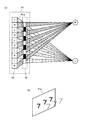
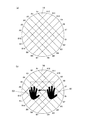
図3には、パララックスバリア方式の表示装置による立体表示の原理について示した。図3(a)は、表示装置41の画像表示部を上方から示したもので、図3(a)の上下方向は表示装置41の左右方向に対応している。表示装置41の液晶パネル42の水平方向の画素には、左画像Lと右画像Rとが交互に表示されるように画像データ処理が行われる。左画像Lとは遊技者の左目に対応する画像であり、右画像Rとは遊技者の右目に対応する画像である。なお、液晶パネル42の裏面側には図示しないバックライト部が配置され、液晶パネルを後方から照らしている。
FIG. 3 shows the principle of stereoscopic display by a parallax barrier display device. 3A shows the image display unit of the
液晶パネル42の前方(図では右方)には、パララックスバリア部43が配置される。このパララックスバリア部43は、バリア43aとスリット43bが交互に設けられており、バリア43aは閉鎖部分であって液晶パネル42から光を遮断し、スリット43bは開口部分であって液晶パネル42から光を通過させることができるもので、スリット43bは所定のピッチで形成されている。したがって、スリット43bとスリット43bとの間がバリア43aとなって画像の一部を遮るようになり、遊技者の目を所定の位置に位置させることにより、右目には右目用の右画像Rだけが見え、左目には左目用の左画像Lだけが見えることになる。その結果、遊技者には、図3(b)に示すように、液晶パネル42に表示されている画像が表示面41aから前方に離間した位置で立体的に見えることになる。
従って、表示装置41は、表示面41aにおいて視認される平面画像と、表示面41aより前または後、もしくは前後方向に離間した位置において視認される立体画像と、を表示可能に構成されていることになる。
A
Therefore, the
また、右画像Rと左画像Lによって生じる視差に変化をつけるように右画像Rと左画像Lの表示を制御することにより、立体表示される画像の飛び出し量を変化させることができる(例えば図36参照)。
なお、立体表示を行うための方式は、パララックスバリア方式に限られるものではなく、レンティキュラ方式やフレームシーケンシャル方式(この場合は各遊技機に専用の眼鏡を備えるようにする)など他の方式を採用してもよい。
Further, by controlling the display of the right image R and the left image L so as to change the parallax caused by the right image R and the left image L, it is possible to change the pop-out amount of the stereoscopically displayed image (for example, FIG. 36).
Note that the 3D display method is not limited to the parallax barrier method, but other methods such as a lenticular method and a frame sequential method (in this case, each gaming machine is equipped with dedicated glasses). May be adopted.
再び図2の説明に戻る。遊技盤30の遊技領域32のセンターケース40の左側には、普通図柄始動ゲート(普図始動ゲート)34が設けられている。センターケース40の左下側には、三つの一般入賞口35が配置され、センターケース40の右下側には、一つの一般入賞口35が配置されている。
これら一般入賞口35、…には、各一般入賞口35に入った遊技球を検出するための入賞口スイッチ35a〜35n(図4参照)が配設されている。
Returning to the description of FIG. On the left side of the
In each of the general winning
また、センターケース40の下方には、特図変動表示ゲームの開始条件を与える始動入賞口(始動入賞領域)36が設けられ、その直下には上部に逆「ハ」の字状に開いて遊技球が流入し易い状態に変換する一対の可動部材37b,37bを備えるとともに内部に第2始動入賞口を有する普通変動入賞装置(普電:始動入賞領域)37が配設されている。
Also, below the
普通変動入賞装置37の一対の可動部材37b,37bは、常時は遊技球の直径程度の間隔をおいて閉じた閉状態(遊技者にとって不利な状態)を保持している。ただし、普通変動入賞装置37の上方には、始動入賞口36が設けられているので、閉じた状態では遊技球が入賞できないようになっている。
そして、普図変動表示ゲームの結果が所定の停止表示態様となった場合には、駆動装置としての普電ソレノイド37c(図4参照)によって、逆「ハ」の字状に開いて普通変動入賞装置37に遊技球が流入し易い開状態(遊技者にとって有利な状態)に変化させられるようになっている。
The pair of
Then, when the result of the normal variation display game becomes a predetermined stop display mode, it is opened in a reverse “C” shape by a general
さらに、普通変動入賞装置37の下方には、特図変動表示ゲームの結果によって遊技球を受け入れない状態と受け入れ易い状態とに変換可能な特別変動入賞装置(大入賞口)38が配設されている。
Further, a special variable winning device (large winning mouth) 38 that can be converted into a state where a game ball is not accepted and a state where it is easy to accept depending on the result of the special figure changing display game is arranged below the normal
特別変動入賞装置38は、上端側が手前側に倒れる方向に回動して開放可能になっているアタッカ形式の開閉扉38cを有しており、補助遊技としての特図変動表示ゲームの結果如何によって大入賞口を閉じた状態(遊技者にとって不利な閉塞状態)から開放状態(遊技者にとって有利な状態)に変換する。
即ち、特別変動入賞装置38は、例えば、駆動装置としての大入賞口ソレノイド38b(図4参照)により駆動される開閉扉38cによって開閉される大入賞口を備え、特別遊技状態中は、大入賞口を閉じた状態から開いた状態に変換することにより大入賞口内への遊技球の流入を容易にさせ、遊技者に所定の遊技価値(賞球)を付与するようになっている。
The special
In other words, the special variable winning
なお、大入賞口の内部(入賞領域)には、当該大入賞口に入った遊技球を検出する検出手段としてのカウントスイッチ38a(図4参照)が配設されている。
特別変動入賞装置38の下方には、入賞口などに入賞しなかった遊技球を回収するアウト口39が設けられている。
また、遊技領域32の外側(例えば、遊技盤30の右下部)には、特図変動表示ゲームをなす第1特図変動表示ゲームや第2特図変動表示ゲーム及び普図始動ゲート34への入賞をトリガとする普図変動表示ゲームを一箇所で実行する一括表示装置50が設けられている。
In addition, a
Below the special variable winning
In addition, on the outside of the game area 32 (for example, in the lower right part of the game board 30), the first special figure fluctuation display game, the second special figure fluctuation display game, and the normal
一括表示装置50は、7セグメント型の表示器(LEDランプ)等で構成された第1特図変動表示ゲーム用の第1特図変動表示部(特図1表示器)51及び第2特図変動表示ゲーム用の第2特図変動表示部(特図2表示器)52と、LEDランプで構成された普図変動表示ゲーム用の変動表示部(普図表示器)53と、同じくLEDランプで構成された各変動表示ゲームの始動記憶数報知用の記憶表示部54〜56を備える。
また、一括表示装置50には、大当りが発生すると点灯して大当り発生を報知する第1遊技状態表示部(第1遊技状態表示器)57、時短状態が発生すると点灯して時短状態発生を報知する第2遊技状態表示部(第2遊技状態表示器)60、遊技機10の電源投入時に大当りの確率状態が高確率状態となっているエラーを表示するエラー表示器(第3遊技状態表示器)58、大当り時のラウンド数(特別変動入賞装置38の開閉回数)を表示するラウンド数表示器59が設けられている。
The
Further, the
特図1表示器51と特図2表示器52における特図変動表示ゲームは、例えば変動表示ゲームの実行中、即ち、表示装置41において飾り特図変動表示ゲームを行っている間は、中央のセグメントを点滅駆動させて変動中であることを表示する。そして、ゲームの結果が「はずれ」のときは、はずれの結果態様として例えば中央のセグメントを点灯状態にし、ゲームの結果が「当り」のときは、当りの結果態様(特別結果態様)としてはずれの結果態様以外の結果態様(例えば「3」や「7」の数字等)を点灯状態にしてゲーム結果を表示する。
The special figure fluctuation display game in the special figure 1
普図表示器53は、変動中はランプを点滅させて変動中であることを表示する。そして、ゲームの結果が「はずれ」のときは、例えばランプを消灯状態にし、ゲームの結果が「当り」のときはランプを点灯状態にしてゲーム結果を表示する。
The
特図1始動記憶表示器54は、特図1表示器51の変動開始条件となる始動入賞口36への入賞球数のうち未消化の球数(始動記憶数=保留数)を表示する。具体的には、保留数が「0」のときは4つのランプを全て消灯状態にし、保留数が「1」のときはランプ1のみを点灯状態にする。また、保留数が「2」のときはランプ1と2を点灯状態にし、保留数が「3」のときはランプ1と2と3を点灯状態にし、保留数が「4」のときは4つのランプ1〜4をすべて点灯状態にする。
The special figure 1 start memory display 54 displays the number of undigested balls (starting memory number = holding number) among the number of winning balls to the start winning
特図2始動記憶表示器55は、特図2表示器52の変動開始条件となる第2始動入賞口(普通変動入賞装置37)の始動記憶数(=保留数)を、特図1始動記憶表示器54と同様にして表示する。
The special figure 2
普図始動記憶表示器56は、普図表示器53の変動開始条件となる普図始動ゲート34の始動記憶数(=保留数)を表示する。例えば保留数が「0」のときはランプ1と2を消灯状態にし、保留数が「1」のときはランプ1のみを点灯状態にする。また、保留数が「2」のときはランプ1と2を点灯状態にし、保留数が「3」のときはランプ1を点滅、ランプ2を点灯状態にし、保留数が「4」のときはランプ1と2を点滅状態にする。
The general-purpose
第1遊技状態表示器57は、例えば通常の遊技状態の場合にはランプを消灯状態にし、大当りが発生している場合にはランプを点灯状態にする。
第2遊技状態表示器60は、例えば通常の遊技状態の場合にはランプを消灯状態にし、時短状態が発生している場合にはランプを点灯状態にする。
For example, the first gaming state indicator 57 turns off the lamp in the normal gaming state, and turns on the lamp when the big hit has occurred.
For example, the second
第3遊技状態表示器58(エラー表示器)は、例えば遊技機10の電源投入時に大当りの確率状態が低確率状態の場合にはランプを消灯状態にし、遊技機10の電源投入時に大当りの確率状態が高確率状態の場合にはランプを点灯状態にする。
For example, the third gaming status indicator 58 (error indicator) turns off the lamp when the jackpot probability state is low when the
ラウンド数表示器59は、例えば、通常の遊技状態の場合にはランプを消灯状態にし、大当りが発生した場合にはその大当りのラウンド数に対応するランプ(2ラウンドor15ラウンド)を点灯状態にする。なお、ラウンド数表示器59は7セグメント型の表示器で構成してもよい。 For example, the round number indicator 59 turns off the lamp in the normal gaming state, and turns on the lamp corresponding to the number of rounds (2 rounds or 15 rounds) when the big hit occurs. . The round number display 59 may be a 7 segment type display.
本実施形態の遊技機10では、図示しない発射装置から遊技領域32に向けて遊技球(パチンコ球)が打ち出されることによって遊技が行われる。打ち出された遊技球は、遊技領域32内の各所に配置された障害釘や風車等の方向転換部材によって転動方向を変えながら遊技領域32を流下し、普図始動ゲート34、一般入賞口35、始動入賞口36、普通変動入賞装置37又は特別変動入賞装置38に入賞するか、遊技領域32の最下部に設けられたアウト口39へ流入し遊技領域32から排出される。そして、一般入賞口35、始動入賞口36、普通変動入賞装置37又は特別変動入賞装置38に遊技球が入賞すると、入賞した入賞口の種類に応じた数の賞球が、払出制御装置200(図4参照)によって制御される払出ユニットから、開閉枠12の上皿21又は下皿23に排出される。
In the
一方、普図始動ゲート34内には、該普図始動ゲート34を通過した遊技球を検出するための非接触型のスイッチなどからなるゲートスイッチ34a(図4参照)が設けられており、遊技領域32内に打ち込まれた遊技球が普図始動ゲート34内を通過すると、ゲートスイッチ34aにより検出されて普図変動表示ゲームが行われる。
また、普図変動表示ゲームを開始できない状態、例えば、既に普図変動表示ゲームが行われ、その普図変動表示ゲームが終了していない状態や、普図変動表示ゲームが当って普通変動入賞装置37が開状態に変換されている場合に、普図始動ゲート34を遊技球が通過すると、普図始動記憶数の上限数未満でならば、普図始動記憶数が加算(+1)されて普図始動記憶が1つ記憶されることとなる。この普図始動入賞の記憶数は、一括表示装置50の始動入賞数報知用の記憶表示部56(普図始動記憶表示器)に表示される。
また、普図始動記憶には、普図変動表示ゲームの当りはずれを決定するための当り判定用乱数値が記憶されるようになっていて、この当り判定用乱数値が判定値と一致した場合に、当該普図変動表示ゲームが当りとなって特定の結果態様(特定結果)が導出されることとなる。
On the other hand, a
In addition, the normal variation display game cannot be started, for example, the normal variation display game has already been played and the normal variation display game has not been completed, When 37 is converted to the open state and the game ball passes through the general figure start
In addition, in the normal chart start memory, a random number value for hit determination for determining a hit error of the normal figure fluctuation display game is stored, and when the random number value for hit determination coincides with the determination value In addition, a specific result mode (specific result) is derived by hitting the common map fluctuation display game.
普図変動表示ゲームは、一括表示装置50に設けられた変動表示部(普図表示器)53で実行されるようになっている。普図表示器53は、普通識別情報(普図、普通図柄)として点灯状態の場合に当りを示し、消灯状態の場合にはずれを示すLEDから構成され、このLEDを点滅表示することで普通識別情報の変動表示を行い、所定の変動表示時間の経過後、LEDを点灯又は消灯することで結果を表示するようになっている。
なお、普通識別情報として例えば数字、記号、キャラクタ図柄などを用い、これを所定時間変動表示させた後、停止表示させることにより行うように構成しても良い。この普図変動表示ゲームの停止表示が特定結果となれば、普図の当りとなって、普通変動入賞装置37の一対の可動部材37bが所定時間(例えば、0.3秒間)開放される開状態となる。これにより、普通変動入賞装置37の内部の第2始動入賞口へ遊技球が入賞し易くなり、第2特図変動表示ゲームが実行される回数が多くなる。
The usual map change display game is executed by a change display unit (common figure display) 53 provided in the
Note that, for example, numbers, symbols, character designs, and the like may be used as the normal identification information, which is displayed by variably displaying for a predetermined time and then stopped. If the stop display of this normal figure change display game is a specific result, the pair of
普図始動ゲート34への通過検出時に抽出した普図乱数値が当り値であるときには、普図表示器53に表示される普通図柄が当り状態で停止し、当り状態となる。このとき、普通変動入賞装置37は、内蔵されている普電ソレノイド37c(図4参照)が駆動されることにより、可動部材37bが所定の時間(例えば、0.3秒間)だけ開放する状態に変換され、遊技球の入賞が許容される。
When the random number value extracted at the time of detection of the passage to the universal chart start
始動入賞口36への入賞球及び普通変動入賞装置37への入賞球は、それぞれは内部に設けられた始動口1スイッチ36aと始動口2スイッチ37aによって検出される。始動入賞口36へ入賞した遊技球は第1特図変動表示ゲームの始動入賞球として検出され、所定の上限数(例えば、4個)を限度に記憶されるとともに、普通変動入賞装置37へ入賞した遊技球は第2特図変動表示ゲームの始動入賞球として検出され、所定の上限数(例えば、4個)を限度に記憶される。
また、この始動入賞球の検出時にそれぞれ大当り乱数値や大当り図柄乱数値、並びに各変動パターン乱数値が抽出され、抽出された乱数値は、遊技制御装置100(図4参照)内の特図記憶領域(RAMの一部)に特図始動記憶として各々所定回数(例えば、最大で4回分)を限度に記憶される。そして、この特図始動記憶の記憶数は、一括表示装置50の始動入賞数報知用の記憶表示部54,55(特図1始動記憶表示器、特図2始動記憶表示器)に表示されるとともに、センターケース40の表示装置41においても保留図柄R1〜R4(例えば図18(a)参照)として表示される。
The winning ball to the
In addition, when the starting winning ball is detected, the jackpot random number value, the jackpot symbol random number value, and each variation pattern random number value are extracted. Each area (a part of the RAM) is stored as a special figure start memory for a predetermined number of times (for example, a maximum of four times). The number stored in the special figure start memory is displayed on the
遊技制御装置100は、始動入賞口36若しくは普通変動入賞装置37への入賞、又はそれらの始動記憶に基づいて、特図1表示器51(変動表示装置)又は特図2表示器52(変動表示装置)で第1又は第2特図変動表示ゲームを行う。
第1特図変動表示ゲーム及び第2特図変動表示ゲームは、複数の特別図柄(特図、識別情報)を変動表示したのち、所定の結果態様を停止表示することで行われる。また、表示装置41(変動表示装置)にて各特図変動表示ゲームに対応して複数種類の識別情報(例えば、数字、記号、キャラクタ図柄など)を変動表示させる飾り特図変動表示ゲームが実行されるようになっている。
そして、特図変動表示ゲームの結果として、特図1表示器51若しくは特図2表示器52の表示態様が特別結果態様となった場合には、大当りとなって特別遊技状態(いわゆる、大当り状態)となる。また、これに対応して表示装置41の表示態様も特別結果態様となる。
The
The first special figure fluctuation display game and the second special figure fluctuation display game are performed by variably displaying a plurality of special symbols (special figures, identification information) and then stopping and displaying a predetermined result form. In addition, a decorative special figure fluctuation display game is executed in which a plurality of types of identification information (for example, numbers, symbols, character designs, etc.) are displayed in a variable manner on the display device 41 (fluctuation display apparatus) corresponding to each special figure fluctuation display game. It has come to be.
As a result of the special figure fluctuation display game, when the display mode of the special figure 1
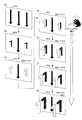
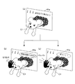
表示装置41における飾り特図変動表示ゲームは、例えば前述した数字等で構成される飾り特別図柄(識別情報)が左(第1特別図柄)、右(第2特別図柄)、中(第3特別図柄)の順に変動表示を開始して、所定時間後に変動している図柄を順次停止させて、特図変動表示ゲームの結果を表示することで行われる。また、表示装置41では、特図始動記憶数に対応する飾り特別図柄による変動表示ゲームを行うとともに、興趣向上のためにキャラクタの出現など多様な演出表示が行われる。
In the decorative special figure variation display game on the
なお、特図1表示器51、特図2表示器52は、別々の表示器でも良いし同一の表示器でも良いが、各々独立して、また、同時には実行しないように各特図変動表示ゲームが表示される。また、表示装置41も、第1特図変動表示ゲームと第2特図変動表示ゲームで別々の表示装置や別々の表示領域を使用するとしても良いし、同一の表示装置や表示領域を使用するとしても良いが、各々独立して、また、同時には実行しないように飾り特図変動表示ゲームが表示される。また、遊技機10に特図1表示器51、特図2表示器52を備えずに、表示装置41のみで特図変動表示ゲームを実行するようにしても良い。
また、第2特図変動表示ゲームは、第1特図変動表示ゲームよりも優先して実行されるようになっている。即ち、第1特図変動表示ゲームと第2特図変動表示ゲームの始動記憶がある場合であって、特図変動表示ゲームの実行が可能となった場合は、第2特図変動表示ゲームが実行されるようになっている。
The special figure 1
Further, the second special figure variation display game is executed with priority over the first special figure variation display game. That is, if there is a start memory of the first special figure fluctuation display game and the second special figure fluctuation display game, and the execution of the special figure fluctuation display game becomes possible, the second special figure fluctuation display game is It is supposed to be executed.
また、第1特図変動表示ゲーム(第2特図変動表示ゲーム)が開始可能な状態で、且つ、始動記憶数が0の状態で、始動入賞口36(若しくは、普通変動入賞装置37)に遊技球が入賞すると、始動権利の発生に伴って始動記憶が記憶されて、始動記憶数が1加算されるととともに、直ちに始動記憶に基づいて、第1特図変動表示ゲーム(第2特図変動表示ゲーム)が開始され、この際に始動記憶数が1減算される。 In addition, in the state where the first special figure fluctuation display game (second special figure fluctuation display game) can be started and the number of start memories is zero, the start winning opening 36 (or the normal fluctuation prize winning device 37) is entered. When the game ball wins, the start memory is stored as the start right is generated, the start memory number is incremented by 1, and the first special figure variation display game (second special figure) is immediately added based on the start memory. (Variable display game) is started, and at this time, the start memory number is decremented by one.
一方、第1特図変動表示ゲーム(第2特図変動表示ゲーム)が直ちに開始できない状態、例えば、既に第1若しくは第2特図変動表示ゲームが行われ、その特図変動表示ゲームが終了していない状態や、特別遊技状態となっている場合に、始動入賞口36(若しくは、普通変動入賞装置37)に遊技球が入賞すると、始動記憶数が上限数未満ならば、始動記憶数が1加算されて始動記憶が1つ記憶されることになる。そして、始動記憶数が1以上となった状態で、第1特図変動表示ゲーム(第2特図変動表示ゲーム)が開始可能な状態(前回の特図変動表示ゲームの終了若しくは特別遊技状態の終了)となると、始動記憶数が1減算されるとともに、記憶された始動記憶に基づいて第1特図変動表示ゲーム(第2特図変動表示ゲーム)が開始される。
以下の説明において、第1特図変動表示ゲームと第2特図変動表示ゲームを区別しない場合は、単に特図変動表示ゲームと称する。
On the other hand, a state in which the first special figure fluctuation display game (second special figure fluctuation display game) cannot be started immediately, for example, the first or second special figure fluctuation display game has already been performed, and the special figure fluctuation display game has ended. If the game ball is won in the start winning opening 36 (or the normal variable prize winning device 37) in a state that is not in the special game state or in the special game state, the start memory number is 1 if the start memory number is less than the upper limit number. By adding, one start memory is stored. Then, in a state where the starting memory number becomes 1 or more, a state in which the first special figure fluctuation display game (second special figure fluctuation display game) can be started (the end of the previous special figure fluctuation display game or the special game state) (End), the start memory number is decremented by 1, and the first special figure fluctuation display game (second special figure fluctuation display game) is started based on the stored start memory.
In the following description, when the first special figure fluctuation display game and the second special figure fluctuation display game are not distinguished, they are simply referred to as a special figure fluctuation display game.
なお、特に限定されるわけではないが、上記始動入賞口36内の始動口1スイッチ36a、普通変動入賞装置37内の始動口2スイッチ37a、ゲートスイッチ34a、一般入賞口スイッチ35a〜35n、カウントスイッチ38a、流路スイッチには、磁気検出用のコイルを備え該コイルに金属が近接すると磁界が変化する現象を利用して遊技球を検出する非接触型の磁気近接センサ(以下、近接スイッチと称する)が使用されている。遊技機10のガラス枠15等に設けられた前枠開放検出スイッチ63や開閉枠(遊技枠)12等に設けられた遊技枠開放検出スイッチ64には、機械的な接点を有するマイクロスイッチを用いることができる。
Although not particularly limited, the starting
図4は、本実施形態の遊技機10の制御システムのブロック図である。
遊技機10は遊技制御装置100を備え、遊技制御装置100は、遊技を統括的に制御する主制御装置(主基板、遊技制御手段)であって、遊技用マイクロコンピュータ(以下、遊技用マイコンと称する)111を有するCPU部110と、入力ポートを有する入力部120と、出力ポートやドライバなどを有する出力部130、CPU部110と入力部120と出力部130との間を接続するデータバス140などからなる。
FIG. 4 is a block diagram of the control system of the
The
上記CPU部110は、アミューズメントチップ(IC)と呼ばれる遊技用マイコン(CPU)111と、入力部120内の近接スイッチ用のインタフェースチップ(近接I/F)121からの信号(始動入賞検出信号)を論理反転して遊技用マイコン111に入力させるインバータなどからなる反転回路112と、水晶振動子のような発振子を備え、CPUの動作クロックやタイマ割込み、乱数生成回路の基準となるクロックを生成する発振回路(水晶発振器)113などを有する。遊技制御装置100及び該遊技制御装置100によって駆動されるソレノイドやモータなどの電子部品には、電源装置400で生成されたDC32V,DC12V,DC5Vなど所定のレベルの直流電圧が供給されて動作可能にされる。
The
電源装置400は、24Vの交流電源から上記DC32Vの直流電圧を生成するAC−DCコンバータやDC32Vの電圧からDC12V,DC5Vなどのより低いレベルの直流電圧を生成するDC−DCコンバータなどを有する通常電源部410と、遊技用マイコン111の内部のRAMに対して停電時に電源電圧を供給するバックアップ電源部420と、停電監視回路や初期化スイッチを有し遊技制御装置100に停電の発生、回復を知らせる停電監視信号や初期化スイッチ信号、リセット信号などの制御信号を生成して出力する制御信号生成部430などを備える。
The
この実施形態では、電源装置400は、遊技制御装置100と別個に構成されているが、バックアップ電源部420及び制御信号生成部430は、別個の基板上あるいは遊技制御装置100と一体、即ち、主基板上に設けるように構成してもよい。遊技盤30及び遊技制御装置100は機種変更の際に交換の対象となるので、実施例のように、電源装置400若しくは主基板とは別の基板にバックアップ電源部420及び制御信号生成部430を設けることにより、交換の対象から外しコストダウンを図ることができる。
In this embodiment, the
上記バックアップ電源部420は、電解コンデンサのような大容量のコンデンサ1つで構成することができる。バックアップ電源は、遊技制御装置100の遊技用マイコン111(特に内蔵RAM)に供給され、停電中あるいは電源遮断後もRAMに記憶されたデータが保持されるようになっている。制御信号生成部430は、例えば通常電源部410で生成された32Vの電圧を監視してそれが例えば17V以下に下がると停電発生を検出して停電監視信号を変化させるとともに、所定時間後にリセット信号を出力する。また、電源投入時や停電回復時にもその時点から所定時間経過後にリセット信号を出力する。
The backup
初期化スイッチ信号は初期化スイッチがオン状態にされたときに生成される信号で、遊技用マイコン111内のRAM111C及び払出制御装置200内のRAMに記憶されている情報を強制的に初期化する。特に限定されるわけではないが初期化スイッチ信号は電源投入時に読み込まれ、停電監視信号は遊技用マイコン111が実行するメインプログラムのメインループの中で繰り返し読み込まれる。リセット信号は強制割込み信号の一種であり、制御システム全体をリセットさせる。
The initialization switch signal is a signal generated when the initialization switch is turned on, and forcibly initializes information stored in the
遊技用マイコン111は、遊技を統括的に制御する制御手段を構成している。具体的には、遊技用マイコン111は、CPU(中央処理ユニット:マイクロプロセッサ)111A、読出し専用のROM(リードオンリメモリ)111B及び随時読出し書込み可能なRAM(ランダムアクセスメモリ)111Cを備える。
The
ROM111Bは、遊技制御のための不変の情報(プログラム、固定データ、各種乱数の判定値等)を不揮発的に記憶し、RAM111Cは、遊技制御時にCPU111Aの作業領域や各種信号や乱数値の記憶領域として利用される。ROM111B又はRAM111Cとして、EEPROMのような電気的に書換え可能な不揮発性メモリを用いてもよい。
The
また、ROM111Bは、例えば、特図変動表示ゲームの実行時間、演出内容、リーチ状態の発生の有無などを規定する変動パターン(変動態様)を決定するための変動パターンテーブルを記憶している。
変動パターンテーブルとは、始動記憶として記憶されている変動パターン乱数1〜3をCPU111Aが参照して変動パターンを決定するためのテーブルである。また、変動パターンテーブルには、結果がはずれとなる場合に選択されるはずれ変動パターンテーブル、結果が15R当りや2R当りとなる場合に選択される大当り変動パターンテーブル等が含まれる。さらに、これらのパターンテーブルには、後半変動パターンテーブル、前半変動パターンテーブルが含まれている。
In addition, the
The variation pattern table is a table for the
また、リーチ(リーチ状態)とは、表示状態が変化可能な表示装置を有し、該表示装置が時期を異ならせて複数の表示結果を導出表示し、該複数の表示結果が予め定められた特別結果態様となった場合に、遊技状態が遊技者にとって有利な遊技状態(特別遊技状態)となる遊技機10において、複数の表示結果の一部がまだ導出表示されていない段階で、既に導出表示されている表示結果が特別結果態様となる条件を満たしている表示状態をいう。また、別の表現をすれば、リーチ状態とは、表示装置の変動表示制御が進行して表示結果が導出表示される前段階にまで達した時点でも、特別結果態様となる表示条件からはずれていない表示態様をいう。そして、例えば、特別結果態様が揃った状態を維持しながら複数の変動表示領域による変動表示を行う状態(いわゆる全回転リーチ)もリーチ状態に含まれる。また、リーチ状態とは、表示装置の表示制御が進行して表示結果が導出表示される前段階にまで達した時点での表示状態であって、表示結果が導出表示される以前に決定されている複数の変動表示領域の表示結果の少なくとも一部が特別結果態様となる条件を満たしている場合の表示状態をいう。
Reach (reach state) has a display device whose display state can change, and the display device derives and displays a plurality of display results at different times, and the plurality of display results are predetermined. In the
よって、例えば、特図変動表示ゲームに対応して表示装置に表示される飾り特図変動表示ゲームが、表示装置における左、中、右の変動表示領域の各々で所定時間複数の識別情報を変動表示した後、左、右、中の順で変動表示を停止して結果態様を表示するものである場合、左、右の変動表示領域で、特別結果態様となる条件を満たした状態(例えば、同一の識別情報)で変動表示が停止した状態がリーチ状態となる。またこの他に、すべての変動表示領域の変動表示を一旦停止した時点で、左、中、右のうち何れか二つの変動表示領域で特別結果態様となる条件を満たした状態(例えば、同一の識別情報となった状態、ただし特別結果態様は除く)をリーチ状態とし、このリーチ状態から残りの一つの変動表示領域を変動表示するようにしても良い。そして、このリーチ状態には複数のリーチ演出が含まれ、特別結果態様が導出される可能性が異なる(信頼度が異なる)リーチ演出として、ノーマルリーチ、スペシャル1リーチ、スペシャル2リーチ、スペシャル3リーチ、スペシャル4リーチ等が設定されている。
Thus, for example, a decorative special figure fluctuation display game displayed on a display device corresponding to a special figure fluctuation display game fluctuates a plurality of identification information for a predetermined time in each of the left, middle, and right fluctuation display areas on the display device. After displaying, when the display of the result mode is stopped in the order of left, right, and middle, the condition that becomes the special result mode is satisfied in the left and right variable display areas (for example, The state in which the variable display is stopped with the same identification information) is the reach state. In addition to this, when the variable display of all the variable display areas is temporarily stopped, the condition that the special result mode is satisfied in any two of the left, middle, and right variable display areas (for example, the same The state in which the identification information is obtained (except for the special result mode) may be set as the reach state, and the remaining one variable display area may be variably displayed from the reach state. This reach state includes a plurality of reach productions, and the possibility that a special result mode is derived (different reliability) includes normal reach, special 1 reach, special 2 reach, special 3 reach,
なお、信頼度は、リーチなし<ノーマルリーチ<スペシャル1リーチ<スペシャル2リーチ<スペシャル3リーチ<スペシャル4リーチの順に高くなるようになっている。また、このリーチ状態は、少なくとも特図変動表示ゲームで特別結果態様が導出される場合(大当りとなる場合)における変動表示態様に含まれるようになっている。即ち、特図変動表示ゲームで特別結果態様が導出されないと判定する場合(はずれとなる場合)における変動表示態様に含まれることもある。よって、リーチ状態が発生した状態は、リーチ状態が発生しない場合に比べて大当りとなる可能性の高い状態である。 The reliability increases in the order of no reach <normal reach <special 1 reach <special 2 reach <special 3 reach <special 4 reach. In addition, this reach state is included in a variable display mode at least in a case where a special result mode is derived in a special figure variable display game (when a big hit is achieved). That is, it may be included in the variable display mode when it is determined that the special result mode is not derived in the special figure variable display game (when it is out of place). Therefore, the state in which the reach state has occurred is a state that is more likely to be a big hit than the case in which the reach state does not occur.
CPU111Aは、ROM111B内の遊技制御用プログラムを実行して、払出制御装置200や演出制御装置300に対する制御信号(コマンド)、ソレノイドや表示装置の駆動信号等を生成して出力して遊技機10全体の制御を行う。
また、図示しないが、遊技用マイコン111は、特図変動表示ゲームの大当り判定用乱数や大当りの図柄を決定するための大当り図柄用乱数、普図変動表示ゲームの当り判定用乱数等を生成するための乱数生成回路と、発振回路113からの発振信号(原クロック信号)に基づいてCPU111Aに対する所定周期(例えば、4ミリ秒)のタイマ割込み信号や乱数生成回路の更新タイミングを与えるクロックを生成するクロックジェネレータを備えている。
The
Although not shown, the
また、CPU111Aは、後述する特図ゲーム処理における始動口スイッチ監視処理(ステップA1)や特図普段処理(ステップA9)にて、ROM111Bに記憶されている複数の変動パターンテーブルの中から、何れか一の変動パターンテーブルを取得する。具体的には、CPU111Aは、特図変動表示ゲームの遊技結果(大当り或いははずれ)や、現在の遊技状態としての特図変動表示ゲームの確率状態(通常確率状態或いは高確率状態)、現在の遊技状態としての普通変動入賞装置37の動作状態(通常動作状態或いは時短動作状態)、始動記憶数などに基づいて、複数の変動パターンテーブルの中から、何れか一の変動パターンテーブルを選択して取得する。
In addition, the
払出制御装置200は、図示しないが、CPU、ROM、RAM、入力インタフェース、出力インタフェース等を備え、遊技制御装置100からの賞球払出し指令(コマンドやデータ)に従って、払出ユニットの払出モータを駆動させ、賞球を払い出させるための制御を行う。また、払出制御装置200は、カードユニットからの貸球要求信号に基づいて払出ユニットの払出モータを駆動させ、貸球を払い出させるための制御を行う。
Although not shown, the
遊技用マイコン111の入力部120には、始動入賞口36内の始動口1スイッチ36a、普通変動入賞装置37内の始動口2スイッチ37a、普図始動ゲート34内のゲートスイッチ34a、一般入賞口スイッチ35a〜35n、カウントスイッチ38aに接続され、これらのスイッチから供給されるハイレベルが11Vでロウレベルが7Vのような負論理の信号が入力され、0V−5Vの正論理の信号に変換するインタフェースチップ(近接I/F)121が設けられている。近接I/F121は、入力の範囲が7V−11Vとされることで、近接スイッチのリード線が不正にショートされたり、スイッチがコネクタから外されたり、リード線が切断されてフローティングになったような異常な状態を検出することができ、異常検知信号を出力するように構成されている。
The input unit 120 of the
近接I/F121の出力はすべて第2入力ポート122へ供給されデータバス140を介して遊技用マイコン111に読み込まれるとともに、主基板100から中継基板70を介して図示しない試射試験装置へ供給されるようになっている。また、近接I/F121の出力のうち始動口1スイッチ36aと始動口2スイッチ37aの検出信号は、第2入力ポート122の他、反転回路112を介して遊技用マイコン111へ入力されるように構成されている。反転回路112を設けているのは、遊技用マイコン111の信号入力端子が、マイクロスイッチなどからの信号が入力されることを想定し、かつ負論理、即ち、ロウレベル(0V)を有効レベルとして検知するように設計されているためである。
All the outputs of the proximity I /
従って、始動口1スイッチ36aと始動口2スイッチ37aとしてマイクロスイッチを使用する場合には、反転回路112を設けずに直接遊技用マイコン111へ検出信号を入力させるように構成することができる。つまり、始動口1スイッチ36aと始動口2スイッチ37aからの負論理の信号を直接遊技用マイコン111へ入力させたい場合には、近接スイッチを使用することはできない。上記のように近接I/F121は、信号のレベル変換機能を有する。このようなレベル変換機能を可能にするため、近接I/F121には、電源装置400から通常のICの動作に必要な例えば5Vのような電圧の他に、12Vの電圧が供給されるようになっている。
Therefore, when a micro switch is used as the
また、入力部120には、遊技機10の開閉枠12等に設けられた不正検出用の磁気センサスイッチ61及び振動センサスイッチ62からの信号及び上記近接I/F121により変換された始動入賞口36内の始動口1スイッチ36a、普通変動入賞装置37内の始動口2スイッチ37a、ゲートスイッチ34a、一般入賞口スイッチ35a〜35n、カウントスイッチ38aからの信号を取り込んでデータバス140を介して遊技用マイコン111に供給する第2入力ポート122が設けられている。第2入力ポート122が保持しているデータは、遊技用マイコン111が第2入力ポート122に割り当てられているアドレスをデコードすることによってイネーブル信号CE1をアサート(有効レベルに変化)することよって、読み出すことができる。後述の他のポートも同様である。
In addition, the input unit 120 includes a signal from the fraud detection
さらに、入力部120には、遊技機10のガラス枠15等に設けられた前枠開放検出スイッチ63及び開閉枠(遊技枠)12等に設けられた遊技枠開放検出スイッチ64からの信号及び払出制御装置200からの払出異常を示すステータス信号や払出し前の遊技球の不足を示すシュート球切れスイッチ信号、オーバーフローを示すオーバーフロースイッチ信号を取り込んでデータバス140を介して遊技用マイコン111に供給する第1入力ポート123が設けられている。オーバーフロースイッチ信号は、下皿23に遊技球が所定量以上貯留されていること(満杯になったこと)を検出したときに出力される信号である。
Further, the input unit 120 receives signals and payouts from the front frame opening
また、入力部120には、電源装置400からの停電監視信号や初期化スイッチ信号、リセット信号などの信号を遊技用マイコン111等に入力するためのシュミットトリガ回路124が設けられており、シュミットトリガ回路124はこれらの入力信号からノイズを除去する機能を有する。電源装置400からの信号のうち停電監視信号と初期化スイッチ信号は、一旦第1入力ポート123に入力され、データバス140を介して遊技用マイコン111に取り込まれる。つまり、前述の各種スイッチからの信号と同等の信号として扱われる。遊技用マイコン111に設けられている外部からの信号を受ける端子の数には制約があるためである。
Further, the input unit 120 is provided with a
一方、シュミットトリガ回路124によりノイズ除去されたリセット信号RSTは、遊技用マイコン111に設けられているリセット端子に直接入力されるとともに、出力部130の各ポートに供給される。また、リセット信号RSTは出力部130を介さずに直接中継基板70に出力することで、試射試験装置へ出力するために中継基板70のポート(図示省略)に保持される試射試験信号をオフするように構成されている。また、リセット信号RSTを中継基板70を介して試射試験装置へ出力可能に構成するようにしてもよい。なお、リセット信号RSTは入力部120の各ポート122,123には供給されない。リセット信号RSTが入る直前に遊技用マイコン111によって出力部130の各ポートに設定されたデータはシステムの誤動作を防止するためリセットする必要があるが、リセット信号RSTが入る直前に入力部120の各ポートから遊技用マイコン111が読み込んだデータは、遊技用マイコン111のリセットによって廃棄されるためである。
On the other hand, the reset signal RST from which noise has been removed by the
出力部130は、データバス140に接続され払出制御装置200へ出力する4ビットのデータ信号とデータの有効/無効を示す制御信号(データストローブ信号)及び演出制御装置300へ出力するデータストローブ信号SSTBを生成する第1出力ポート131と、演出制御装置300へ出力する8ビットのデータ信号を生成する第2出力ポート132とを備える。遊技制御装置100から払出制御装置200及び演出制御装置300へは、パラレル通信でデータが送信される。また、出力部130には、演出制御装置300の側から遊技制御装置100へ信号を入力できないようにするため、即ち、片方向通信を担保するために第1出力ポート131からの上記データストローブ信号SSTB及び第2出力ポート132からの8ビットのデータ信号を出力する単方向のバッファ133が設けられている。なお、第1出力ポート131から払出制御装置200へ出力する信号に対してもバッファを設けるようにしてもよい。
The
さらに、出力部130には、データバス140に接続され図示しない認定機関の試射試験装置へ変動表示ゲームの特図図柄情報を知らせるデータや大当りの確率状態を示す信号などを中継基板70を介して出力するバッファ134が実装可能に構成されている。このバッファ134は遊技店に設置される実機(量産販売品)としてのパチンコ遊技機の遊技制御装置(主基板)には実装されない部品である。なお、近接I/F121から出力される始動口スイッチなど加工の必要のないスイッチの検出信号は、バッファ134を通さずに中継基板70を介して試射試験装置へ供給される。
In addition, the
一方、磁気センサスイッチ61や振動センサスイッチ62のようにそのままでは試射試験装置へ供給できない検出信号は、一旦遊技用マイコン111に取り込まれて他の信号若しくは情報に加工されて、例えば遊技機が遊技制御できない状態であることを示すエラー信号としてデータバス140からバッファ134、中継基板70を介して試射試験装置へ供給される。なお、中継基板70には、上記バッファ134から出力された信号を取り込んで試射試験装置へ供給するポートや、バッファを介さないスイッチの検出信号の信号線を中継して伝達するコネクタなどが設けられている。中継基板70上のポートには、遊技用マイコン111から出力されるチップイネーブル信号CEも供給され、該信号CEにより選択制御されたポートの信号が試射試験装置へ供給されるようになっている。
On the other hand, detection signals such as the
また、出力部130には、データバス140に接続され特別変動入賞装置38を開成させるソレノイド(大入賞口ソレノイド)38bや普通変動入賞装置37の可動部材37bを開成させるソレノイド(普電ソレノイド)37cの開閉データと、一括表示装置50のLEDのカソード端子が接続されているデジット線のオン/オフデータを出力するための第3出力ポート135、一括表示装置50に表示する内容に応じてLEDのアノード端子が接続されているセグメント線のオン/オフデータを出力するための第4出力ポート136、大当り情報など遊技機10に関する情報を外部情報端子71へ出力するための第5出力ポート137が設けられている。外部情報端子71から出力された遊技機10に関する情報は、例えば遊技店に設置された情報収集端末や遊技場内部管理装置(図示省略)に供給される。
In addition, the
さらに、出力部130には、第3出力ポート135から出力される大入賞口ソレノイド38bの開閉データ信号を受けてソレノイド駆動信号や普電ソレノイド37cの開閉データ信号を受けてソレノイド駆動信号を生成し出力する第1ドライバ(駆動回路)138a、第3出力ポート135から出力される一括表示装置50の電流引き込み側のデジット線のオン/オフ駆動信号を出力する第2ドライバ138b、第4出力ポート136から出力される一括表示装置50の電流供給側のセグメント線のオン/オフ駆動信号を出力する第3ドライバ138c、第5出力ポート137から管理装置等の外部装置へ供給する外部情報信号を外部情報端子71へ出力する第4ドライバ138dが設けられている。
Further, the
上記第1ドライバ138aには、32Vで動作するソレノイドを駆動できるようにするため、電源電圧としてDC32Vが電源装置400から供給される。また、一括表示装置50のセグメント線を駆動する第3ドライバ138cには、DC12Vが供給される。デジット線を駆動する第2ドライバ138bは、表示データに応じたデジット線を電流で引き抜くためのものであるため、電源電圧は12V又は5Vのいずれであってもよい。12Vを出力する第3ドライバ138cによりセグメント線を介してLEDのアノード端子に電流を流し込み、接地電位を出力する第2ドライバ138bによりカソード端子よりセグメント線を介して電流を引き抜くことで、ダイナミック駆動方式で順次選択されたLEDに電源電圧が流れて点灯される。外部情報信号を外部情報端子71へ出力する第4ドライバ138dは、外部情報信号に12Vのレベルを与えるため、DC12Vが供給される。なお、バッファ134や第3出力ポート135、第1ドライバ138a等は、遊技制御装置100の出力部130、即ち、主基板ではなく、中継基板70側に設けるようにしてもよい。
The
さらに、出力部130には、外部の検査装置500へ各遊技機の識別コードやプログラムなどの情報を送信するためのフォトカプラ139が設けられている。フォトカプラ139は、遊技用マイコン111が検査装置500との間でシリアル通信によってデータの送受信を行えるように双方通信可能に構成されている。なお、かかるデータの送受信は、通常の汎用マイクロプロセッサと同様に遊技用マイコン111が有するシリアル通信端子を利用して行われるため、入力ポート122,123のようなポートは設けられていない。
Further, the
次に、図5を用いて、演出制御装置300の構成について説明する。
演出制御装置300は、遊技制御手段(遊技制御装置100)からの指令情報に基づき前記変動表示ゲームの表示制御を行う演出制御手段であって、遊技用マイコン111と同様にアミューズメントチップ(IC)からなる主制御用マイコン(1stCPU)311と、該1stCPU311の制御下でもっぱら映像制御を行う映像制御用マイコン(2ndCPU)312と、該2ndCPU312からのコマンドやデータに従って表示装置41への映像表示のための画像処理を行うグラフィックプロセッサとしてのVDP(Video Display Processor)313と、各種のメロディや効果音などをスピーカ19a,19bから再生させるため音の出力を制御する音源LSI314を備えている。
Next, the configuration of the
The
上記主制御用マイコン(1stCPU)311と映像制御用マイコン(2ndCPU)312には、各CPUが実行するプログラムを格納したPROM(プログラマブルリードオンリメモリ)からなるプログラムROM321、322がそれぞれ接続され、VDP313にはキャラクタ画像や映像データが記憶された画像ROM323が接続され、音源LSI314には音声データが記憶された音声ROM324が接続されている。主制御用マイコン(1stCPU)311は、遊技用マイコン111からのコマンドを解析し、演出内容を決定して映像制御用マイコン312へ出力映像の内容を指示したり、音源LSI314への再生音の指示、装飾ランプの点灯、モータの駆動制御、演出時間の管理などの処理を実行する。主制御用マイコン(1stCPU)311と映像制御用マイコン(2ndCPU)312の作業領域を提供するRAMは、それぞれのチップ内部に設けられている。なお、作業領域を提供するRAMはチップの外部に設けるようにしてもよい。
The main control microcomputer (1st CPU) 311 and the video control microcomputer (2nd CPU) 312 are connected to program
特に限定されるわけではないが、主制御用マイコン(1stCPU)311と映像制御用マイコン(2ndCPU)312との間、主制御用マイコン(1stCPU)311と音源LSI314との間は、それぞれシリアル方式でデータの送受信が行われ、映像制御用マイコン(2ndCPU)312との間、主制御用マイコン(1stCPU)311とVDP313との間は、パラレル方式でデータの送受信が行われるように構成されている。パラレル方式でデータを送受信することで、シリアルの場合よりも短時間にコマンドやデータを送信することができる。VDP313には、画像ROM323から読み出されたキャラクタなどの画像データを展開したり加工したりするのに使用される超高速なVRAM(ビデオRAM)313aや、画像を拡大、縮小処理するためのスケーラ313b、LVDS(小振幅信号伝送)方式で表示装置41へ送信する映像信号を生成する信号変換回路313cなどが設けられている。
Although not particularly limited, a serial system is used between the main control microcomputer (1st CPU) 311 and the video control microcomputer (2nd CPU) 312 and between the main control microcomputer (1st CPU) 311 and the
VDP313から主制御用マイコン311へは表示装置41の映像と開閉枠12や遊技盤30に設けられている装飾ランプの点灯を同期させるために垂直同期信号VSYNCが入力される。さらに、VDP313から映像制御用マイコン312へは、VRAMへの描画の終了等処理状況を知らせるため割込み信号INT0〜n及び映像制御用マイコン312からのコマンドやデータの受信待ちの状態にあることを知らせるためのウェイト信号WAITが入力される。また、映像制御用マイコン312から主制御用マイコン311へは、映像制御用マイコン312が正常に動作していることを知らせるとともにコマンドの送信タイミングを与える同期信号SYNCが入力される。主制御用マイコン311と音源LSI314との間は、ハンドシェイク方式でコマンドやデータの送受信を行うために、呼び掛け(コール)信号CTSと応答(レスポンス)信号RTSが交換される。
A vertical synchronization signal VSYNC is input from the
なお、映像制御用マイコン(2ndCPU)312には、主制御用マイコン(1stCPU)311よりも高速なつまり高価なCPUが使用されている。主制御用マイコン(1stCPU)311とは別に映像制御用マイコン(2ndCPU)312を設けて処理を分担させることによって、主制御用マイコン(1stCPU)311のみでは実現困難な大画面で動きの速い映像を表示装置41に表示させることが可能となるとともに、映像制御用マイコン(2ndCPU)312と同等な処理能力を有するCPUを2個使用する場合に比べてコストの上昇を抑制することができる。また、CPUを2つ設けることによって、2つのCPUの制御プログラムを別々に並行して開発することが可能となり、これによって新機種の開発期間を短縮することができる。
Note that the video control microcomputer (2ndCPU) 312 uses a CPU that is faster or more expensive than the main control microcomputer (1stCPU) 311. By providing a video control microcomputer (2ndCPU) 312 separately from the main control microcomputer (1stCPU) 311 and sharing the processing, it is possible to display a fast moving image on a large screen that is difficult to achieve with the main control microcomputer (1stCPU) 311 alone. It is possible to display on the
また、演出制御装置300には、遊技制御装置100から送信されてくるコマンドを受信するインタフェースチップ(コマンドI/F)331が設けられている。このコマンドI/F331を介して、遊技制御装置100から演出制御装置300へ送信された変動開始コマンド、始動口入賞演出コマンド、始動口入賞演出図柄コマンド、客待ちデモコマンド、ファンファーレコマンド、確率情報コマンド、変動停止コマンド、大当り終了コマンド、エラー指定コマンド等を、演出制御指令信号として受信する。遊技制御装置100の遊技用マイコン111はDC5Vで動作し、演出制御装置300の主制御用マイコン(1stCPU)311はDC3.3Vで動作するため、コマンドI/F331には信号のレベル変換の機能が設けられている。
In addition, the
また、演出制御装置300には、遊技盤30(センターケース40を含む)に設けられているLED(発光ダイオード)を有する盤装飾装置46を駆動制御する盤装飾LED制御回路332、開閉枠12に設けられているLED(発光ダイオード)を有する枠装飾装置18を駆動制御する枠装飾LED制御回路333、遊技盤30(センターケース40を含む)に設けられている盤演出装置44(例えば表示装置41における演出表示と協働して演出効果を高める可動役物等)を駆動制御する盤演出モータ/SOL制御回路334、開閉枠12に設けられている枠演出装置45(例えばムービングライト16を動作させるモータ等)を駆動制御する枠演出モータ制御回路335が設けられている。なお、ランプやモータ及びソレノイドなどを駆動制御するこれらの制御回路332〜335は、アドレス/データバス340を介して主制御用マイコン(1stCPU)311と接続されている。
The
さらに、演出制御装置300には、開閉枠12に設けられたプッシュボタン25に内蔵されているスイッチ25aや、上記盤演出装置44内のモータの初期位置を検出する演出モータスイッチ、ガラス枠15に設けられたガラス前操作センサ29のオン/オフ状態を検出して主制御用マイコン(1stCPU)311へ検出信号を入力するスイッチ入力回路336、開閉枠12に設けられた上スピーカ19aを駆動するオーディオパワーアンプなどからなるアンプ回路337a、開閉枠12に設けられた下スピーカ19bを駆動するアンプ回路337bが設けられている。
Further, the
電源装置400の通常電源部410は、上記のような構成を有する演出制御装置300やそれによって制御される電子部品に対して所望のレベルの直流電圧を供給するため、モータやソレノイドを駆動するためのDC32V、液晶パネル等からなる表示装置41を駆動するためのDC12V、コマンドI/F331の電源電圧となるDC5Vの他に、LEDやスピーカを駆動するためのDC18Vやこれらの直流電圧の基準としたり電源モニタランプを点灯させるのに使用するNDC24Vの電圧を生成するように構成されている。さらに、主制御用マイコン(1stCPU)311や映像制御用マイコン(2ndCPU)312として、3.3Vあるいは1.2Vのような低電圧で動作するLSIを使用する場合には、DC5Vに基づいてDC3.3VやDC1.2Vを生成するためのDC−DCコンバータが演出制御装置300に設けられる。なお、DC−DCコンバータは通常電源部410に設けるようにしてもよい。
The normal
電源装置400の制御信号生成部430により生成されたリセット信号RSTは、主制御用マイコン311、映像制御用マイコン312、VDP313、音源LSI314、ランプやモータなどを駆動制御する制御回路332〜335、スピーカを駆動するアンプ回路337a,337bに供給され、これらをリセット状態にする。また、この実施例においては、映像制御用マイコン312の有する汎用のポートを利用して、VDP313に対するリセット信号を生成して供給する機能を有するように構成されている。これにより、映像制御用マイコン312とVDP313の動作の連携性を向上させることができる。
The reset signal RST generated by the control
次に、これらの制御回路において行われる遊技制御について説明する。
遊技制御装置100の遊技用マイコン111のCPU111Aでは、普図始動ゲート34に備えられたゲートスイッチ34aからの遊技球の検出信号の入力に基づき、普図の当り判定用乱数値を抽出してROM111Bに記憶されている判定値と比較し、普図変動表示ゲームの当りはずれを判定する処理を行う。そして、普図表示器53に、識別情報(識別図柄)を所定時間変動表示した後、停止表示する普図変動表示ゲームを表示する処理を行う。この普図変動表示ゲームの結果が当りの場合は、普図表示器53に特別の結果態様を表示するとともに、普電ソレノイド37cを動作させ、普通変動入賞装置37の可動部材37b,37bを所定時間(例えば、0.3秒間)上述のように開放する制御を行う。
なお、普図変動表示ゲームの結果がはずれの場合は、普図表示器53にはずれの結果態様を表示する制御を行う。
Next, game control performed in these control circuits will be described.
The
In addition, when the result of the normal map change display game is out of order, control is performed on the
また、始動入賞口36に備えられた始動口1スイッチ36aからの遊技球の検出信号の入力に基づき始動入賞(始動記憶)をRAM111C等に記憶し、この始動記憶に基づき、第1特図変動表示ゲームの大当り判定用乱数値を抽出してROM111Bに記憶されている判定値と比較し、第1特図変動表示ゲームの当りはずれを判定する処理を行う。
また、普通変動入賞装置37に備えられた始動口2スイッチ37aからの遊技球の検出信号の入力に基づき始動記憶をRAM111C等に記憶し、この始動記憶に基づき、第2特図変動表示ゲームの大当り判定用乱数値を抽出してROM111Bに記憶されている判定値と比較し、第2特図変動表示ゲームの当りはずれを判定する処理を行う。
Further, based on the input of the game ball detection signal from the
In addition, the start memory is stored in the
そして、遊技制御装置100のCPU111Aは、上記の第1特図変動表示ゲームや第2特図変動表示ゲームの判定結果を含む制御信号(演出制御コマンド)を、演出制御装置300に出力する。そして、特図1表示器51や特図2表示器52に、識別情報(識別図柄)を所定時間変動表示した後、停止表示する特図変動表示ゲームを表示する処理を行う。
また、演出制御装置300では、遊技制御装置100からの制御信号に基づき、表示装置41で特図変動表示ゲームに対応した飾り特図変動表示ゲームを表示する処理を行う。
さらに、演出制御装置300では、遊技制御装置100からの制御信号に基づき、スピーカ19a,19bからの音の出力、各種LEDの発光を制御する処理等を行う。
Then, the
In addition, in the
Furthermore, in the
そして、遊技制御装置100のCPU111Aは、特図変動表示ゲームの結果が当りの場合は、特図1表示器51や特図2表示器52に特別結果態様を表示するとともに、特別遊技状態を発生させる処理を行う。
特別遊技状態を発生させる処理においては、CPU111Aは、例えば、大入賞口ソレノイド38bにより特別変動入賞装置38の開閉扉38cを開放させ、大入賞口内への遊技球の流入を可能とする制御を行う。
そして、特図変動表示ゲームの結果が当りの場合は、大入賞口に所定個数(例えば、10個)の遊技球が入賞するか、大入賞口の開放から所定時間(例えば、25秒又は1秒)が経過するかの何れかの条件が達成されるまで大入賞口を開放することを1ラウンドとし、これを所定ラウンド回数(例えば、15回又は2回)継続する(繰り返す)制御(サイクル遊技)を行う。
また、特図変動表示ゲームの結果がはずれの場合は、特図1表示器51や特図2表示器52にはずれの結果態様を表示する制御を行う。
Then, the
In the process of generating the special game state, the
Then, when the result of the special figure variation display game is a win, a predetermined number (for example, 10) of game balls wins the big prize opening or a predetermined time (for example, 25 seconds or 1) from the opening of the big prize opening. A control (cycle) in which a grand prize opening is opened until one of the following conditions is achieved, and this is repeated (repeated) for a predetermined number of rounds (for example, 15 or 2 times). Play).
Further, when the result of the special figure variation display game is out of order, the special figure 1
また、遊技制御装置100は、特図変動表示ゲームの結果態様に基づき、特別遊技状態の終了後に、遊技状態として確変状態を発生可能となっている。
この確変状態は、特図変動表示ゲームにて当り結果となる確率が、通常確率状態に比べて高い状態(高確率状態)である。また、第1特図変動表示ゲーム及び第2特図変動表示ゲームのどちらの特図変動表示ゲームの結果態様に基づき確変状態となっても、第1特図変動表示ゲーム及び第2特図変動表示ゲームの両方が確変状態となる。
In addition, the
This probability variation state is a state (high probability state) in which the probability of a hit result in the special figure variation display game is higher than the normal probability state. In addition, the first special figure variation display game and the second special figure variation display game, regardless of which one of the first special figure variation display game and the second special figure variation display game results in a certain variation state. Both display games are in a probable state.
また、遊技制御装置100は、特図変動表示ゲームの結果態様に基づき、特別遊技状態の終了後に、遊技状態として時短状態を発生可能となっている。
この時短状態においては、普図変動表示ゲーム及び普通変動入賞装置37を時短動作状態とする制御を行う。具体的には、時短状態においては、上述の普図変動表示ゲームの実行時間が第1の変動表示時間よりも短い第2の変動表示時間となるように制御され(例えば、10秒が1秒)、これにより、単位時間当りの普通変動入賞装置37の開放回数が実質的に多くなるように制御される。また、時短状態においては、普図変動表示ゲームが当り結果となって普通変動入賞装置37が開放される場合に、開放時間が通常状態の第1開放時間よりも長い第2開放時間となるように制御される(例えば、0.3秒が1.7秒)。また、時短状態においては、普図変動表示ゲームの1回の当り結果に対して、普通変動入賞装置37の開放回数が1回の第1開放回数ではなく、2回以上の複数回(例えば、3回)の第2開放回数に設定される。
なお、普図変動表示ゲームの実行時間を第2の変動表示時間(例えば、1秒)とする制御と、普通変動入賞装置37の開放態様を開放時間が第2開放時間(例えば、1.7秒)とし、且つ、普図変動表示ゲームの1回の当り結果に対する開放回数が第2開放回数(例えば、3回)とする制御は、何れか一方のみを行っても良いし、両方を行っても良い。また、時短動作状態においては、普図変動表示ゲームの当り結果となる確率が通常動作状態より高くなるように制御してもよい。
これにより、普通変動入賞装置37に遊技球が入賞し易くなり、第2特図変動表示ゲームの始動が容易となる。
In addition, the
In this time-short state, control is performed so that the normal-variation display game and the normal
It should be noted that the execution time of the normal variation display game is set to the second variation display time (for example, 1 second), and the release mode of the normal
As a result, the game ball can easily win the normal
なお、確変状態と普図変動表示ゲーム及び普通変動入賞装置37の時短動作状態は、それぞれ独立して発生可能であり、両方を同時に発生することも可能であるし、一方のみを発生させることも可能である。
In addition, the time variation operation state of the probability variation state, the normal variation display game, and the normal variation
次に、上記遊技制御装置100の遊技用マイクロコンピュータ(遊技用マイコン)111によって実行される制御について説明する。
遊技用マイコン111による制御処理は、ループ処理として繰り返されるメインルーチンであるメイン処理(主に図6及び図7参照)と、メイン処理に対する割り込みルーチンとして、所定時間周期(例えば4ms)で行われるタイマ割込み処理(図8参照)とからなる。
Next, control executed by the game microcomputer (game microcomputer) 111 of the
The control process by the
〔メイン処理〕
まず、メイン処理について説明する。
メイン処理は、電源が投入されることで開始される。このメイン処理においては、図6に示すように、まず、割込みを禁止する処理(ステップS1)を行ってから、割込みが発生したときに実行するジャンプ先のベクタアドレスを設定する割込みベクタ設定処理(ステップS2)、割込みが発生したときにレジスタ等の値を退避する領域の先頭アドレスであるスタックポインタを設定するスタックポインタ設定処理(ステップS3)、割込み処理のモードを設定する割込みモード設定処理(ステップS4)を行う。
[Main processing]
First, the main process will be described.
The main process is started when the power is turned on. In this main process, as shown in FIG. 6, an interrupt vector setting process (step S1) is first performed to set a jump destination vector address to be executed when an interrupt occurs. Step S2), a stack pointer setting process for setting a stack pointer that is the start address of an area for saving a value of a register or the like when an interrupt occurs (Step S3), an interrupt mode setting process for setting an interrupt processing mode (Step S3) S4) is performed.
次に、払出制御装置(払出基板)200のプログラムが正常に起動するのを待つため例えば4msの時間待ちを行う(ステップS5)。これにより、電源投入の際に仮に遊技制御装置100が先に立ち上がって払出制御装置200が立ち上がる前にコマンドを払出制御装置200へ送ってしまい、払出制御装置200がコマンドを取りこぼすのを回避することができる。その後、RAMやEEPROM等の読出し書込み可能なRWM(リードライトメモリ)のアクセス許可をし、全出力ポートに出力が無い状態にするOFFデータを出力する(ステップS6,S7)。また、シリアルポート(遊技用マイコン111に予め搭載されているポートで、本実施形態では、払出制御装置200や演出制御装置300とパラレル通信を行っているため使用しない)を使用しない状態に設定する処理を行う(ステップS8)。
Next, in order to wait for the program of the payout control apparatus (payout board) 200 to start up normally, for example, a time of 4 ms is waited (step S5). As a result, when the power is turned on, the
続いて、電源装置400内の初期化スイッチがONしているか否かを判定する(ステップS9)。ここで、初期化スイッチがOFFと判定した場合(ステップS9;No)には、RWM内に複数設けられている停電検査領域のうち、停電検査領域1のデータの値をチェックし(ステップS10)、停電検査領域1の値が正常な停電検査領域チェックデータ1であるか否かの判定を行う(ステップS11)。
このステップS11で停電検査領域1の値が正常な停電検査領域チェックデータ1であると判定した場合(ステップS11;Yes)には、停電検査領域2のデータの値をチェックし(ステップS12)、停電検査領域2の値が正常な停電検査領域チェックデータ2であるか否かの判定を行う(ステップS13)。
このステップS13で停電検査領域2の値が正常な停電検査領域チェックデータ2であると判定した場合(ステップS13;Yes)には、チェックサムと呼ばれるデータを算出する処理(ステップS14)を行い、算出したチェックサムと電源遮断時のチェックサムとを比較して(ステップS15)、値が一致するか否かを判定する(ステップS16)。
Subsequently, it is determined whether or not the initialization switch in the
If it is determined in step S11 that the value of the power
If it is determined in step S13 that the value of the power
また、ステップS9で初期化スイッチがONと判定した場合(ステップS9;Yes)、ステップS11で停電検査領域1の値が正常でないと判定した場合(ステップS11;No)、ステップS13で停電検査領域2の値が正常でないと判定した場合(ステップS13;No)、或いは、ステップS16でチェックサムが一致しないと判定した場合(ステップS16;No)には、図7のステップS24へジャンプする。
If it is determined in step S9 that the initialization switch is ON (step S9; Yes), if it is determined in step S11 that the value of the power
また、ステップS16でチェックサムが一致すると判定した場合(ステップS16;Yes)には、図7のステップS17へ移行して、全ての停電検査領域をクリアする処理(ステップS17)、チェックサム領域をクリアする処理(ステップS18)を行ってから、エラーや不正監視に係る領域をリセットする(ステップS19)。
次に、RWM内の遊技状態を記憶する領域を調べて遊技状態が高確率状態であるか否かを判定する(ステップS20)。ここで、高確率でないと判定した場合(ステップS20;No)は、ステップS21,S22をスキップしてステップS23へ移行する。
If it is determined in step S16 that the checksums match (step S16; Yes), the process proceeds to step S17 in FIG. 7 to clear all power failure inspection areas (step S17). After performing the clearing process (step S18), the area related to the error or fraud monitoring is reset (step S19).
Next, an area for storing the gaming state in the RWM is examined to determine whether or not the gaming state is a high probability state (step S20). If it is determined that the probability is not high (step S20; No), steps S21 and S22 are skipped and the process proceeds to step S23.
また、ステップS20で高確率であると判定した場合(ステップS20;Yes)には、高確率の報知フラグ領域にON情報をセーブしてから(ステップS21)、例えば一括表示装置50に設けられる高確率報知LED(エラー表示器58)をオン(点灯)させるONデータをセグメントに対応する領域(ポート136)にセーブして(ステップS22)、ステップS23へ移行する。ステップS23では、特図ゲーム処理番号に対応する停電復旧時のコマンドを送信してステップS29へ進む。
If it is determined in step S20 that there is a high probability (step S20; Yes), the ON information is saved in the high-probability notification flag area (step S21), and then the high information provided in the
一方、ステップS9,S11,S13,S16からステップS24へジャンプした場合には、まずCPU111Aが使用するRAM内の、アクセス禁止領域より前の全作業領域をクリアする処理(ステップS24)、アクセス禁止領域より後の全スタック領域をクリアする処理(ステップS25)を行ってから、初期化すべき領域に電源投入時の初期値をセーブする(ステップS26)。それから、RWMをクリアしたことに関する外部情報を出力する期間の時間値を設定し(ステップS27)、電源投入時のコマンドを演出制御装置300へ送信する処理(ステップS28)を行って、ステップS29へ進む。
On the other hand, when jumping from step S9, S11, S13, S16 to step S24, first, the process of clearing all work areas before the access prohibited area in the RAM used by the
ステップS29では、遊技用マイコン111(クロックジェネレータ)内のタイマ割込み信号及び乱数更新トリガ信号(CTC)を発生するCTC(Counter/Timer Circuit)
回路を起動する処理を行う。
なお、CTC回路は、遊技用マイコン111内のクロックジェネレータに設けられている。クロックジェネレータは、水晶発振器113からの発振信号(原クロック信号)を分周する分周回路と、分周された信号に基づいてCPU111Aに対して所定周期(例えば、4ms)のタイマ割込み信号及び乱数生成回路へ供給する乱数更新のトリガを与える信号CTCを発生するCTC回路とを備えている。
In step S29, a CTC (Counter / Timer Circuit) that generates a timer interrupt signal and a random number update trigger signal (CTC) in the gaming microcomputer 111 (clock generator).
Performs processing to start the circuit.
The CTC circuit is provided in a clock generator in the
上記ステップS29のCTC起動処理の後は、乱数生成回路を起動設定する処理を行う(ステップS30)。具体的には、乱数生成回路内の所定のレジスタ(CTC更新許可レジスタ)へ乱数生成回路を起動させるためのコード(指定値)の設定などがCPU111Aによって行われる。それから、電源投入時の乱数生成回路内の所定のレジスタ(ソフト乱数レジスタ1〜n)の値を、対応する各種初期値乱数(大当り図柄を決定する乱数(大当り図柄乱数1、大当り図柄乱数2)、普図の当りを決定する乱数(当り乱数))の初期値(スタート値)としてRWMの所定領域にセーブしてから(ステップS31)、割込みを許可する(ステップS32)。本実施例で使用するCPU111A内の乱数生成回路においては、電源投入毎にソフト乱数レジスタの初期値が変わるように構成されているため、この値をCPU側で生成する各種初期値乱数の初期値(スタート値)とすることで、ソフトウェアで生成される乱数の規則性を崩すことができ、遊技者による不正な乱数の取得を困難にすることができる。
After the CTC activation process in step S29, a process for activating and setting the random number generation circuit is performed (step S30). Specifically, the
続いて、各種初期値乱数の値を更新して乱数の規則性を崩すための初期値乱数更新処理(ステップS33)を行う。なお、本実施形態においては、特に限定されるわけではないが、大当り乱数は乱数生成回路において生成される乱数(大当り乱数)を使用して生成するように構成されている。つまり、大当り乱数はハードウェアで生成されるハード乱数であり、大当り図柄乱数、当り乱数はソフトウェアで生成されるソフト乱数である。 Subsequently, an initial value random number update process (step S33) is performed to update the values of various initial value random numbers to break the regularity of the random numbers. In the present embodiment, although not particularly limited, the big hit random number is configured to be generated using a random number (big hit random number) generated in a random number generation circuit. That is, the big hit random number is a hard random number generated by hardware, and the big hit symbol random number is a soft random number generated by software.
上記ステップS33の初期値乱数更新処理の後、停電監視信号をチェックする回数を設定する(ステップS34)。そして、電源装置400から入力されている停電監視信号をポート及びデータバスを介して読み込んでチェックし、停電監視信号がONであるか否かを判定する(ステップS35)。ステップS35で、停電監視信号がONでないと判定した場合(ステップS35;No)には、ステップS33に戻り、上記初期値乱数更新処理と停電監視信号のチェック(ループ処理)を繰り返し行う。初期値乱数更新処理(ステップS33)の前に割り込みを許可する(ステップS32)ことによって、初期値乱数更新処理中にタイマ割込みが発生すると割込み処理が優先して実行されるようになり、タイマ割込みが初期値乱数更新処理によって待たされることで割込み処理が圧迫されるのを回避することができる。
After the initial value random number update process in step S33, the number of times that the power failure monitoring signal is checked is set (step S34). Then, the power failure monitoring signal input from the
なお、上記ステップS33での初期値乱数更新処理は、メイン処理のほか、タイマ割込み処理の中においても初期値乱数更新処理を行う方法もあり、そのような方法を採用した場合には両方で初期値乱数更新処理が実行されるのを回避するため、メイン処理で初期値乱数更新処理を行う場合には割込みを禁止してから更新して割込みを解除する必要があるが、本実施例のようにタイマ割込み処理の中での初期値乱数更新処理はせず、メイン処理内のみにした場合には初期値乱数更新処理の前に割込みを解除しても何ら問題はなく、それによってメイン処理が簡素化されるという利点がある。 Note that the initial value random number update process in step S33 includes a method of performing an initial value random number update process in the timer interrupt process in addition to the main process. In order to avoid execution of value random number update processing, when performing initial value random number update processing in the main processing, it is necessary to disable interrupt and then update to cancel the interrupt. If the initial value random number update process in the timer interrupt process is not performed in the main process and only the main process is performed, there is no problem even if the interrupt is canceled before the initial value random number update process. There is an advantage that it is simplified.
上記ステップS35において、停電監視信号がONであると判定した場合(ステップS35;Yes)には、設定したチェック回数の分だけONが継続されたか否かを判定する(ステップS36)。そして、継続されなかったと判定した場合(ステップS36;No)には、ステップS35に戻り、停電が発生したか否かの判定(ループ処理)を繰り返し行う。また、ステップS36において、継続されたと判定した場合(ステップS36;Yes)、すなわち、停電が発生していると判定した場合には、一旦割込みを禁止する処理(ステップS37)、全出力ポートにOFFデータを出力する処理(ステップS38)を行う。その後さらに、停電復旧検査領域1に停電復旧検査領域チェックデータ1をセーブする処理(ステップS39)、停電復旧検査領域2に停電復旧検査領域チェックデータ2をセーブする処理(ステップS40)、RWMの電源遮断時のチェックサムを算出する処理(ステップS41)を行った後、算出したチェックサムをチェックサム領域にセーブして(ステップS42)、RWMへのアクセスを禁止する処理(ステップS43)を行ってから、遊技機の電源が遮断されるのを待つ。このように、停電復旧検査領域にチェックデータをセーブするとともに、電源遮断時のチェックサムを算出することで、停電等に伴う遊技機10の電源遮断の前にRWMに記憶されていた情報が正しくバックアップされているか否かを、遊技機10の電源再投入時に判断することができる。
If it is determined in step S35 that the power failure monitoring signal is ON (step S35; Yes), it is determined whether or not ON is continued for the set number of checks (step S36). And when it determines with not having been continued (step S36; No), it returns to step S35 and repeats determination (loop process) of whether the power failure generate | occur | produced. If it is determined in step S36 that the operation has been continued (step S36; Yes), that is, if it is determined that a power failure has occurred, processing for temporarily prohibiting interruption (step S37), all output ports are turned OFF. A process of outputting data (step S38) is performed. Thereafter, a process for saving the power failure recovery inspection
〔タイマ割込み処理〕
次に、タイマ割込み処理について説明する。
タイマ割込み処理は、クロックジェネレータ内のCTC回路で生成される周期的なタイマ割込み信号がCPU111Aに入力されることで開始される。遊技用マイコン111においてタイマ割込みが発生すると、図8のタイマ割込み処理が開始される。
[Timer interrupt processing]
Next, timer interrupt processing will be described.
The timer interrupt process is started when a periodic timer interrupt signal generated by the CTC circuit in the clock generator is input to the
タイマ割込み処理が開始されると、遊技制御装置100の遊技用マイコン111は、まず所定のレジスタに保持されている値をRWMに移すレジスタ退避の処理(ステップS51)を行う。なお、本実施形態において遊技用マイコンとして使用しているZ80系のマイコンでは、当該処理を表レジスタに保持されている値を裏レジスタに退避することで置き換えることができる。
次いで、各種センサ(始動口1スイッチ36a、始動口2スイッチ37a、普図のゲートスイッチ34a、カウントスイッチ38aなど)からの入力の取込み、即ち、各入力ポートの状態を読み込む入力処理(ステップS52)を行う。
次いで、各種処理でセットされた出力データに基づき、ソレノイド(大入賞口SOL38b、普電SOL37c)等のアクチュエータの駆動制御などを行うための出力処理(ステップS53)を行う。
When the timer interrupt process is started, the
Next, input processing of various sensors (start
Next, based on the output data set in various processes, an output process (step S53) for performing drive control of an actuator such as a solenoid (large winning opening SOL38b, ordinary electric power SOL37c) or the like is performed.
次いで、各種処理で送信バッファにセットされたコマンドを演出制御装置300や払出制御装置200等に出力するコマンド送信処理(ステップS54)、乱数更新処理1(ステップS55)、乱数更新処理2(ステップS56)を行う。
次いで、始動口1スイッチ36a、始動口2スイッチ37a、普図のゲートスイッチ34a、入賞口スイッチ35a…35n、カウントスイッチ38aから正常な信号の入力があるか否かの監視や、エラーの監視(開閉枠12やガラス枠15が開放されていないかなど)を行う入賞口スイッチ/エラー監視処理(ステップS57)を行う。
次いで、特図変動表示ゲームに関する処理を行う特図ゲーム処理(ステップS58)、普図変動表示ゲームに関する処理を行う普図ゲーム処理(ステップS59)を行う。
なお、特図ゲーム処理(ステップS58)の詳細については後述する。
Next, a command transmission process (step S54), a random number update process 1 (step S55), and a random number update process 2 (step S56) for outputting commands set in the transmission buffer in various processes to the
Next, it is monitored whether there is a normal signal input from the
Next, a special figure game process (step S58) for performing a process related to the special figure variation display game, and a general figure game process (step S59) for performing a process related to the common figure variation display game are performed.
Details of the special figure game process (step S58) will be described later.
次いで、遊技機10に設けられ、特図変動表示ゲームの表示や遊技に関する各種情報を表示するセグメントLEDを所望の内容を表示するように駆動するセグメントLED編集処理(ステップS60)、磁気センサスイッチ61や振動センサスイッチ62からの検出信号をチェックして異常がないか判定する磁気エラー監視処理(ステップS61)、外部の各種装置に出力する信号を出力バッファにセットする外部情報編集処理(ステップS62)を行う。
そして、割込み要求をクリアして割込みの終了を宣言する処理(ステップS63)を行い、ステップS41で退避したレジスタのデータを復帰する処理(ステップS64)を行った後、割込みを許可する処理(ステップS65)を行って、タイマ割込み処理を終了する。
Next, a segment LED editing process (step S60) that is provided in the
Then, a process of clearing the interrupt request and declaring the end of the interrupt (step S63) is performed, a process of restoring the register data saved in step S41 (step S64), and a process of permitting the interrupt (step S63). S65) is performed, and the timer interrupt process is terminated.
〔特図ゲーム処理〕
次に、前述のタイマ割込み処理における特図ゲーム処理(ステップS58)の詳細について説明する。
当該特図ゲーム処理では、始動口1スイッチ36a及び始動口2スイッチ37aの入力の監視と、特図変動表示ゲームに関する処理全体の制御、特図の表示の設定を行う。
[Special Figure Game Processing]
Next, the details of the special game process (step S58) in the timer interrupt process described above will be described.
In the special figure game process, the input of the
図9に示すように、特図ゲーム処理では、まず、始動口1スイッチ36a及び始動口2スイッチ37aの入賞を監視する始動口スイッチ監視処理(ステップA1)を行う。この始動口スイッチ監視処理では、始動入賞口36、第2始動入賞口をなす普通変動入賞装置37に遊技球の入賞があると、各種乱数(大当り乱数など)の抽出を行い、当該入賞に基づく特図変動表示ゲームの開始前の段階で入賞に基づく遊技結果を事前に判定する遊技結果事前判定を行う。
なお、始動口スイッチ監視処理(ステップA1)の詳細については後述する。
As shown in FIG. 9, in the special figure game process, first, a start port switch monitoring process (step A1) for monitoring a winning of the
The details of the start port switch monitoring process (step A1) will be described later.
次いで、カウントスイッチ監視処理(ステップA2)を行う。このカウントスイッチ監視処理では、特別変動入賞装置38内に設けられたカウントスイッチ38aのカウント数を監視する処理を行う。
Next, a count switch monitoring process (step A2) is performed. In this count switch monitoring process, a process of monitoring the count number of the
次いで、特図ゲーム処理タイマが、既にタイムアップしたか、又は当該特図ゲーム処理タイマを更新(−1)した後にタイムアップしたかをチェックして(ステップA3)、特図ゲーム処理タイマがタイムアップしたか否かを判定する(ステップA4)。
ステップS4で、特図ゲーム処理タイマがタイムアップしたと判定した場合(ステップA4;Yes)には、特図ゲーム処理番号に対応する処理に分岐させるために参照する特図ゲームシーケンス分岐テーブルをレジスタに設定する処理(ステップA5)を行って、当該テーブルを用いて特図ゲーム処理番号に対応する処理の分岐先アドレスを取得する処理(ステップA6)を行う。
次いで、分岐処理終了後のリターンアドレスをスタック領域に退避させる処理(ステップA7)を行った後、特図ゲーム処理番号に応じてゲーム分岐処理(ステップA8)を行う。
Next, it is checked whether the special figure game processing timer has already timed up, or the special figure game processing timer has been updated (-1) and then timed up (step A3). It is determined whether or not it is up (step A4).
If it is determined in step S4 that the special figure game process timer has expired (step A4; Yes), a special figure game sequence branch table to be referred to for branching to the process corresponding to the special figure game process number is registered. (Step A5) is performed, and a process (step A6) of acquiring a branch destination address of the process corresponding to the special figure game process number is performed using the table.
Next, after performing the process of saving the return address after the branch process to the stack area (step A7), the game branch process (step A8) is performed according to the special figure game process number.
ステップA8で、特図ゲーム処理番号が「0」の場合は、特図変動表示ゲームの変動開始を監視し、特図変動表示ゲームの変動開始の設定や演出の設定や、特図変動中処理を行うために必要な情報の設定等を行う特図普段処理(ステップA9)を行う。 If the special figure game process number is “0” in step A8, the fluctuation start of the special figure fluctuation display game is monitored, the fluctuation start setting of the special figure fluctuation display game, the setting of the production, the special figure fluctuation processing A special figure routine process (step A9) for setting information necessary for performing the process is performed.
また、ステップA8で、特図ゲーム処理番号が「1」の場合は、特図の停止表示時間の設定や、特図表示中処理を行うために必要な情報の設定等を行う特図変動中処理(ステップA10)を行う。 Also, if the special figure game process number is “1” in step A8, the special figure is changing to set the stop display time of the special figure or to set the information necessary for performing the special figure display process. Processing (step A10) is performed.
また、ステップA8で、特図ゲーム処理番号が「2」の場合は、特図変動表示ゲームの遊技結果が大当りであれば、大当りの種類(2R大当りor15R大当り)に応じたファンファーレコマンドの設定や、各大当り(2R大当りor15R大当り)の大入賞口開放パターンに応じたファンファーレ時間の設定や、ファンファーレ/インターバル中処理を行うために必要な情報の設定等を行う特図表示中処理(ステップA11)を行う。 In addition, when the special figure game process number is “2” in step A8, if the game result of the special figure fluctuation display game is a big hit, the fanfare command setting corresponding to the type of big hit (2R big hit or 15R big hit) Special figure display processing (step A11) for setting the fanfare time according to the big winning opening opening pattern of each jackpot (2R jackpot or 15R jackpot), setting information necessary for performing the fanfare / interval processing, etc. I do.
また、ステップA8で、特図ゲーム処理番号が「3」の場合は、大入賞口の開放時間の設定や開放回数の更新、大入賞口開放中処理を行うために必要な情報の設定等を行うファンファーレ/インターバル中処理(ステップA12)を行う。 Also, if the special figure game process number is “3” in step A8, setting of the opening time of the big prize opening, updating of the number of times of opening, setting of information necessary for performing the processing during opening of the big prize opening, etc. The fanfare / interval processing (step A12) to be performed is performed.
また、ステップA8で、特図ゲーム処理番号が「4」の場合は、大当りラウンドが最終ラウンドでなければインターバルコマンドを設定する一方で最終ラウンドであれば大当り終了画面のコマンドを設定する処理や、大入賞口残存球処理を行うために必要な情報の設定等を行う大入賞口開放中処理(ステップA13)を行う。 In step A8, when the special figure game process number is “4”, if the big hit round is not the final round, an interval command is set. A process for opening a special prize opening (step A13) for setting information necessary for performing the special prize remaining ball process is performed.
また、ステップA8で、特図ゲーム処理番号が「5」の場合は、大当りラウンドが最終ラウンドであれば大入賞口内にある残存球が排出されるための時間を設定する処理や、大当り終了処理を行うために必要な情報の設定等を行う大入賞口残存球処理(ステップA14)を行う。 In step A8, when the special figure game process number is “5”, if the big hit round is the final round, a process for setting the time for discharging the remaining balls in the big prize opening, or a big hit end process The prize winning opening remaining ball process (step A14) for setting information necessary for performing the process is performed.
また、ステップA8で、特図ゲーム処理番号が「6」の場合は、特図普段処理(ステップA9)を行うために必要な情報の設定等を行う大当り終了処理(ステップA15)を行う。 If the special figure game process number is “6” in step A8, the big hit end process (step A15) for setting information necessary for performing the special figure normal process (step A9) is performed.
次いで、特図1表示器51の変動を制御するためのテーブルを準備した後(ステップA16)、特図1表示器51に係る図柄変動制御処理(ステップA17)を行う。
次いで、特図2表示器52の変動を制御するためのテーブルを準備した後(ステップA18)、特図2表示器52に係る図柄変動制御処理(ステップA19)を行い、当該特図ゲーム処理を終了する。
Next, after preparing a table for controlling the fluctuation of the special figure 1 display 51 (step A16), the symbol fluctuation control process (step A17) related to the special figure 1
Next, after preparing a table for controlling the fluctuation of the special figure 2 indicator 52 (step A18), the symbol fluctuation control process (step A19) related to the special figure 2
一方、ステップA4で、特図ゲーム処理タイマがタイムアップしていないと判定した場合(ステップA4;No)には、処理をステップA16に移行して、それ以降の処理を行う。
従って、遊技制御装置100は、遊技領域を流下する遊技球の始動入賞領域への入賞に基づき変動表示ゲームの進行制御を行う遊技制御手段として機能する。
On the other hand, when it is determined in step A4 that the special figure game process timer has not expired (step A4; No), the process proceeds to step A16, and the subsequent processes are performed.
Therefore, the
〔始動口スイッチ監視処理〕
次に、上述の特図ゲーム処理における始動口スイッチ監視処理の詳細について説明する。
図10に示すように、始動口スイッチ監視処理では、まず、始動入賞口36(始動口1)による始動口入賞演出コマンドを設定するテーブルを準備して、始動口1による保留の情報を設定するテーブルを準備した後(ステップA111)、特図始動口スイッチ共通処理(ステップA112)を行う。
なお、ステップA112における特図始動口スイッチ共通処理の詳細については、ステップA117における特図始動口スイッチ共通処理とともに後述する。
[Starter switch monitoring process]
Next, details of the start port switch monitoring process in the above-described special figure game process will be described.
As shown in FIG. 10, in the start port switch monitoring process, first, a table for setting a start port winning effect command by the start winning port 36 (start port 1) is prepared, and information on hold by the
The details of the special figure start port switch common process in step A112 will be described later together with the special figure start port switch common process in step A117.
次いで、普通電動役物(普通変動入賞装置37)が作動中である、即ち、普通変動入賞装置37が作動して遊技球の入賞が可能な開状態となっているか否かをチェックして(ステップA113)、普通電動役物が作動中であると判定した場合(ステップA113;Yes)には、処理をステップA116に移行して、それ以降の処理を行う。
一方、ステップA113で、普通電動役物が作動中でないと判定した場合(ステップA113;No)には、普通変動入賞装置37への不正入賞数が不正発生判定個数以上であるかをチェックして(ステップA114)、不正入賞数が不正発生判定個数以上であるか否かを判定する処理(ステップA115)を行う。
普通変動入賞装置37は、閉状態では遊技球が入賞不可能であり、開状態でのみ遊技球が入賞可能である。よって、閉状態で遊技球が入賞した場合は何らかの異常や不正が発生した場合であり、このような閉状態で入賞した遊技球があった場合はその数を不正入賞数として計数する。そして、このように計数された不正入賞数が所定の不正発生判定個数(上限値)以上であるかが判定される。
Next, it is checked whether or not the ordinary electric accessory (ordinary variation winning device 37) is in operation, that is, whether or not the ordinary
On the other hand, if it is determined in step A113 that the ordinary electric accessory is not in operation (step A113; No), it is checked whether the number of fraudulent winnings to the normal
The normal
ステップA115で、不正入賞数が不正判定個数以上でないと判定した場合(ステップA115;No)には、普通変動入賞装置37(始動口2)による始動口入賞演出コマンドを設定するテーブルを準備して、始動口2による保留の情報を設定するテーブルを準備した後(ステップA116)、特図始動口スイッチ共通処理(ステップA117)を行って、当該始動口スイッチ監視処理を終了する。
また、ステップA115で、不正入賞数が不正判定個数以上であると判定された場合(ステップA115;Yes)にも、当該始動口スイッチ監視処理を終了する。即ち、第2始動記憶をそれ以上発生させないようにする。
If it is determined in step A115 that the number of fraudulent winnings is not equal to or greater than the number of fraud determinations (step A115; No), a table for setting a start opening winning effect command by the normal variation winning device 37 (starting opening 2) is prepared. Then, after preparing a table for setting information on hold by the start port 2 (step A116), the special start port switch common process (step A117) is performed, and the start port switch monitoring process is terminated.
Further, when it is determined in step A115 that the number of illegal winnings is equal to or greater than the number of fraud determinations (step A115; Yes), the start port switch monitoring process is also terminated. That is, the second start memory is not generated any more.
〔特図始動口スイッチ共通処理〕
次に、前述の始動口スイッチ監視処理における特図始動口スイッチ共通処理(ステップA112、A117)の詳細について説明する。
当該特図始動口スイッチ共通処理は、始動口1スイッチ36aや始動口2スイッチ37aの入力があった場合に、各々の入力について共通して行われる処理である。
[Special figure start port switch common processing]
Next, details of the special-purpose start-port switch common processing (steps A112 and A117) in the above-described start-port switch monitoring processing will be described.
The special figure start port switch common process is a process performed in common for each input when there is an input from the
図11に示すように、特図始動口スイッチ共通処理では、まず、始動口1スイッチ36a及び始動口2スイッチ37aのうち、監視対象の始動口スイッチ(例えば、始動口1スイッチ36a等)に入力があるか否かをチェックして(ステップA201)、監視対象の始動口スイッチに入力がないと判定した場合(ステップA202;No)には、当該特図始動口スイッチ共通処理を終了する。
一方、ステップA202で、監視対象の始動口スイッチに入力があると判定した場合(ステップA202;Yes)には、当該監視対象の始動口スイッチの始動口入賞フラグをセーブした後(ステップA203)、監視対象のハード乱数ラッチレジスタに抽出された大当り乱数をロードし、準備する(ステップA204)。
As shown in FIG. 11, in the special figure start port switch common processing, first, of the
On the other hand, if it is determined in step A202 that there is an input to the monitored start port switch (step A202; Yes), after saving the start port winning flag of the monitored start port switch (step A203), The big hit random number extracted is loaded into the monitored hard random number latch register and prepared (step A204).
次いで、始動口1スイッチ36a及び始動口2スイッチ37aのうち、監視対象の始動口スイッチ(例えば、始動口1スイッチ36a等)への入賞の回数に関する情報が遊技機10の外部の管理装置に対して出力された回数(始動口信号出力回数)をロードする(ステップA205)。そして、当該ロードした値を更新(+1)し、出力回数がオーバーフローするか否かをチェックして(ステップA206)、出力回数がオーバーフローするか否かを判定する(ステップS207)。
Next, of the
ステップS207で、出力回数がオーバーフローしないと判定した場合(ステップA207;No)には、更新後の値をRWMの始動口信号出力回数領域にセーブして(ステップA208)、処理をステップA209に移行する。
一方、ステップA207で、出力回数がオーバーフローしたと判定した場合(ステップA207;Yes)には、処理をステップA209に移行する。
If it is determined in step S207 that the number of outputs does not overflow (step A207; No), the updated value is saved in the start signal output number area of the RWM (step A208), and the process proceeds to step A209. To do.
On the other hand, if it is determined in step A207 that the output count has overflowed (step A207; Yes), the process proceeds to step A209.
そして、ステップA209にて、始動口1スイッチ36a及び始動口2スイッチ37aのうち、監視対象の始動口スイッチ(例えば、始動口1スイッチ36a等)に対応する更新対象の特図保留(始動記憶)数が上限値未満か否かをチェックして(ステップA209)、特図保留数が上限値未満か否かを判定する処理(ステップA210)を行う。
Then, in step A209, among the
ステップA210で、特図保留数が上限値未満であると判定した場合(ステップA210;Yes)には、更新対象の特図保留数(例えば、特図1保留数等)を更新(+1)する処理(ステップA211)を行う。
次いで、始動口1スイッチ36a及び始動口2スイッチ37aのうち、監視対象の始動口スイッチ(例えば、始動口1スイッチ36a等)の飾り特図保留数コマンド(MODE)を準備した後(ステップA212)、特図保留数に対応する飾り特図保留数コマンド(ACTION)を準備して(ステップA213)、コマンド設定処理(ステップA214)を行う。
If it is determined in step A210 that the number of special figure hold is less than the upper limit (step A210; Yes), the number of special figure hold to be updated (for example, the number of special figure hold 1) is updated (+1). Processing (step A211) is performed.
Next, after preparing the decoration special figure reservation number command (MODE) of the start port switch to be monitored (for example, the
次いで、特図保留数に対応する乱数セーブ領域のアドレスを算出する処理(ステップA215)を行った後、大当り乱数をRWMの大当り乱数セーブ領域にセーブする(ステップA216)。
次いで、監視対象の始動口スイッチの大当り図柄乱数を抽出し、準備して(ステップA217)、当該大当り図柄乱数をRWMの大当り図柄乱数セーブ領域にセーブする(ステップA218)。
Next, after performing the process of calculating the address of the random number save area corresponding to the special figure hold number (step A215), the big hit random number is saved in the big hit random number save area of the RWM (step A216).
Next, the jackpot symbol random number of the starter switch to be monitored is extracted and prepared (step A217), and the jackpot symbol random number is saved in the jackpot symbol random number saving area of the RWM (step A218).
次いで、対応する変動パターン乱数1を抽出して、RWMの変動パターン乱数1セーブ領域にセーブし(ステップA219)、対応する変動パターン乱数2を抽出して、RWMの変動パターン乱数2セーブ領域にセーブし(ステップA220)、対応する変動パターン乱数3を抽出して、RWMの変動パターン乱数3セーブ領域にセーブ(ステップA221)する。このステップA216,A218〜A221でセーブされた各種乱数が1個の始動記憶となる。この後、特図保留情報判定処理(ステップA222)を行って、当該特図始動口スイッチ共通処理を終了する。なお、特図保留情報判定処理の詳細については後述する。
従って、遊技制御措置100のRAM111Cは、始動入賞領域への遊技球の入賞に基づいて変動表示ゲーム(特図変動表示ゲーム)の実行に関する複数の乱数を抽出し、該変動表示ゲームの始動記憶として所定個数を上限に記憶することが可能な始動記憶保留手段として機能する。
Next, the corresponding fluctuation pattern
Therefore, the
一方、ステップA210で、特図保留数が上限値未満でないと判定した場合(ステップA210;No)には、ステップA202に係る始動口スイッチの入力が始動口1スイッチ36aの入力であるか否かをチェックして(ステップA223)、始動口1スイッチ36aの入力であるか否かを判定する(ステップS224)。
On the other hand, if it is determined in step A210 that the special figure hold number is not less than the upper limit (step A210; No), whether or not the input of the start port switch according to step A202 is the input of the
ステップS224で、始動口1スイッチ36aの入力であると判定した場合(ステップA224;Yes)には、飾り特図保留数コマンド(オーバーフローコマンド)を準備し(ステップA225)、コマンド設定処理(ステップA226)を行って、当該特図始動口スイッチ共通処理を終了する。
一方、ステップA224で、始動口1スイッチ36aの入力でないと判定された場合(ステップA224;No)にも、当該特図始動口スイッチ共通処理を終了する。
If it is determined in step S224 that the input is for the
On the other hand, when it is determined in step A224 that the input is not the
〔特図保留情報判定処理〕
次に、前述の特図始動口スイッチ共通処理における特図保留情報判定処理(ステップA222)の詳細について説明する。
当該特図保留情報判定処理は、対応する始動記憶に基づく特図変動表示ゲームの開始タイミングより前に当該始動記憶に対応した結果関連情報の判定を行う先読み処理である。
[Special figure hold information judgment processing]
Next, the details of the special figure hold information determination process (step A222) in the special figure start port switch common process described above will be described.
The special figure hold information determination process is a prefetching process for determining the result related information corresponding to the start memory before the start timing of the special figure variation display game based on the corresponding start memory.
図12に示すように、特図保留情報判定処理では、まず、先読み演出を実行してよい条件を満たしているかチェックして(ステップA231)、先読み演出を実行してよい条件を満たしているか否かを判定する(ステップS232)。
ここで、「先読み演出を実行してよい条件」とは、特図始動口スイッチ共通処理のステップA202に係る始動口スイッチの入力が始動口2スイッチ37aの入力であること、又は当該始動口スイッチの入力が始動口1スイッチ36aの入力の場合には、普通変動入賞装置37の開放延長機能が作動中でない、すなわち、普通変動入賞装置37がサポート中(時短動作状態中)でなく、且つ、大当り中でないことを意味する。つまり、特図始動口スイッチ共通処理のステップA202に係る始動口スイッチの入力が始動口2スイッチ37aの場合は、普通変動入賞装置37がサポート中、又は大当り中であるかにかかわらず、当該始動記憶に対応した結果関連情報の判定を行う先読み処理を行うこととなる。
As shown in FIG. 12, in the special figure hold information determination process, first, it is checked whether or not a condition for executing the prefetch effect is satisfied (step A231), and whether or not the condition for executing the prefetch effect is satisfied. Is determined (step S232).
Here, “the condition under which the pre-reading effect may be executed” is that the input of the start port switch according to step A202 of the special-purpose start port switch common process is the input of the
ステップA232で、先読み演出を実行してよい条件を満たしていないと判定した場合(ステップA232;No)には、当該特図保留情報判定処理を終了する。
一方、ステップS232で、先読み演出を実行してよい条件を満たしていると判定した場合(ステップA232;Yes)には、大当り判定処理(ステップA233)を行い、ステップA233における大当り判定処理の判定結果が大当りであるか否かを判定する(ステップA234)。
If it is determined in step A232 that the condition for executing the prefetch effect is not satisfied (step A232; No), the special figure hold information determination process is terminated.
On the other hand, if it is determined in step S232 that the conditions for executing the prefetch effect are satisfied (step A232; Yes), the big hit determination process (step A233) is performed, and the determination result of the big hit determination process in step A233 Is a big hit (step A234).
ステップS234で、ステップA233における大当り判定処理の判定結果が大当りであると判定した場合(ステップA234;Yes)には、監視対象の始動口スイッチに対応する大当り図柄乱数チェックテーブルを設定し(ステップA235)、大当り図柄乱数をチェックし、対応する大当り情報テーブルを取得し、設定して(ステップA236)、ステップA238へ移行する。
一方、ステップS234で、ステップA233における大当り判定処理の判定結果が大当りでないと判定した場合(ステップA234;No)には、はずれ情報テーブルを設定し(ステップA237)、ステップA238へ移行する。
If it is determined in step S234 that the determination result of the big hit determination process in step A233 is a big hit (step A234; Yes), a big hit symbol random number check table corresponding to the starter switch to be monitored is set (step A235). ), The jackpot symbol random number is checked, the corresponding jackpot information table is acquired, set (step A236), and the process proceeds to step A238.
On the other hand, when it is determined in step S234 that the determination result of the big hit determination process in step A233 is not a big hit (step A234; No), a loss information table is set (step A237), and the process proceeds to step A238.
そして、ステップA238にて、設定した情報テーブル(大当り情報テーブル、又は、はずれ情報テーブル)から図柄情報を取得し、取得した図柄情報を図柄情報(作業用)領域にセーブする(ステップA238)。
次いで、設定した情報テーブルから始動口入賞演出図柄コマンド(遊技結果情報)を取得し、取得した始動口入賞演出図柄コマンドを入賞演出図柄コマンド領域にセーブする(ステップA239)。
Then, in step A238, symbol information is acquired from the set information table (a jackpot information table or a loss information table), and the acquired symbol information is saved in the symbol information (work) area (step A238).
Next, the start opening winning effect symbol command (game result information) is acquired from the set information table, and the acquired starting opening winning effect symbol command is saved in the winning effect symbol command area (step A239).
次いで、監視対象の始動口スイッチの始動口入賞フラグを準備し(ステップA240)、監視対象の始動口入賞演出コマンド設定テーブルを準備し(ステップA241)、特図情報設定処理(ステップA242)、後半変動パターン設定処理(ステップA243)、変動パターン設定処理(ステップA244)を行う。
次いで、前半変動番号に対応する始動口入賞演出コマンド(MODE)を算出して準備し(ステップA245)、後半変動番号の値を始動口入賞演出コマンド(ACTION)(遊技結果情報)として準備し(ステップA246)、コマンド設定処理(ステップA247)を行う。
次いで、始動口入賞演出図柄コマンドをロードし、準備して(ステップA248)、コマンド設定処理(ステップA249)を行い、当該特図保留情報判定処理を終了する。
従って、遊技制御装置100は、始動記憶保留手段(遊技制御装置100)に始動記憶として記憶された乱数に基づいて変動表示ゲーム(特図変動表示ゲーム)の結果を事前に判定し、遊技結果情報(始動口入賞演出コマンド、始動口入賞演出図柄コマンド)を生成する遊技結果事前判定手段、および遊技結果事前判定手段(遊技制御装置100)により生成された遊技結果情報を事前判定情報として演出制御手段(演出制御装置300)に送信することが可能な事前判定情報送信手段として機能する。
Next, a start opening prize flag of the start opening switch to be monitored is prepared (step A240), a start opening winning effect command setting table to be monitored is prepared (step A241), special figure information setting processing (step A242), and the latter half. A variation pattern setting process (step A243) and a variation pattern setting process (step A244) are performed.
Next, a start opening prize effect command (MODE) corresponding to the first variation number is calculated and prepared (step A245), and the second half variation number value is prepared as a start opening prize effect command (ACTION) (game result information) ( Step A246) and command setting processing (step A247) are performed.
Next, the start opening winning effect design command is loaded and prepared (step A248), a command setting process (step A249) is performed, and the special figure holding information determination process is terminated.
Therefore, the
次に、上記演出制御装置300の主制御用マイコン311によって実行される制御について説明する。
Next, the control executed by the
〔1stシーン制御処理〕
図13には、1stシーン制御処理のフローチャートを示した。この1stシーン制御処理では、まず、テストモード中であるかを判定し(ステップB61)、テストモード中である場合(ステップB61;Yes)は、1stシーン制御処理を終了する。また、テストモード中でない場合(ステップB61;No)は、シーン変更コマンドを受信したか否かを判定する(ステップB62)。
[1st scene control processing]
FIG. 13 shows a flowchart of the 1st scene control process. In this 1st scene control process, first, it is determined whether or not the test mode is in effect (step B61). If the test mode is in effect (step B61; Yes), the 1st scene control process is terminated. When the test mode is not being executed (step B61; No), it is determined whether a scene change command has been received (step B62).
シーン変更コマンドは、遊技制御装置100から演出制御装置300に送信される遊技に関する各種のコマンドである。このシーン変更コマンドを受信した場合(ステップB62;Yes)は、更新する遊技状態(現在の遊技状態)を取得し(ステップB63)、有効なコマンドであるかを判定する(ステップB64)。有効なコマンドであるかの判定(ステップB64)では、受信したシーン変更コマンドが取得した現在の遊技状態に対して有効なものであるかを判定する。そして、有効なコマンドである場合(ステップB64;Yes)は、受信コマンドをセーブし(ステップB65)、演出リクエストフラグをセットして(ステップB66)、受信したコマンドのコマンド識別子による分岐処理(ステップB67)を行う。
The scene change commands are various commands relating to games transmitted from the
一方、シーン変更コマンドを受信していない場合(ステップB62;No)や、有効なコマンドでなかった場合(ステップB64;No)は、受信したコマンドのコマンド識別子による分岐処理(ステップB67)を行う。この場合、直近の有効であったコマンドの識別子による分岐を行う。 On the other hand, when the scene change command has not been received (step B62; No) or when it is not a valid command (step B64; No), branch processing (step B67) based on the command identifier of the received command is performed. In this case, a branch is performed based on the identifier of the command that was most recently valid.
コマンド識別子による分岐処理(ステップB67)では、受信したコマンドに基づき実行する処理を選択する。電源投入コマンドを受信した場合は電源投入時に必要な処理を行う電源投入処理(ステップB68)を行う。また、停電復旧コマンドを受信した場合は停電復旧時に必要な処理を行う停電復旧(客待ち以外)処理(ステップB69)を行う。また、客待ちデモコマンドを受信した場合は客待ちデモの表示に関する処理等を行う客待ち処理(ステップB70)を行う。 In the branch process based on the command identifier (step B67), a process to be executed based on the received command is selected. When a power-on command is received, a power-on process (step B68) is performed to perform a process necessary when the power is turned on. Further, when a power failure recovery command is received, a power failure recovery (other than customer waiting) processing (step B69) for performing processing necessary at the time of power failure recovery is performed. When a customer waiting demo command is received, a customer waiting process (step B70) for performing processing related to display of the customer waiting demo is performed.
また、変動パターンコマンドを受信した場合は飾り特図変動表示ゲームの実行に関する処理等を行う変動中処理(ステップB71)を行う。この変動中処理(ステップB71)では、飾り特図変動表示ゲームを行うために必要な情報の設定を行う。この飾り特図変動表示ゲームを行うために必要な情報の設定では、例えば、遊技制御装置100から送信された変動パターンコマンドに含まれる情報(大当りか否か、モード情報、変動パターン情報など)に基づき演出(変動パターンや変動時間など)の設定を行う。また、図柄停止コマンドを受信した場合は飾り特図変動表示ゲームにおける識別情報の変動表示を停止して結果態様を表示する処理である図柄停止処理(ステップB72)を行う。この図柄停止処理(ステップB72)では、飾り特図変動表示ゲームにおける結果の停止表示時間などの設定を行う。 In addition, when a variation pattern command is received, a variation processing (step B71) for performing processing related to the execution of the decoration special figure variation display game is performed. In the process during change (step B71), information necessary for playing the decoration special figure change display game is set. In the setting of information necessary for playing this decoration special figure variation display game, for example, information included in the variation pattern command transmitted from the game control device 100 (whether it is a big hit, mode information, variation pattern information, etc.) Based on this, production (variation pattern, variation time, etc.) is set. Further, when a symbol stop command is received, symbol stop processing (step B72), which is processing for stopping the variation display of the identification information in the decorative special symbol variation display game and displaying the result mode, is performed. In the symbol stop process (step B72), the result stop display time in the special symbol variation display game is set.
また、ファンファーレコマンドを受信した場合は特別遊技状態の開始に関する処理であるファンファーレ処理(ステップB73)を行う。また、大入開放n回目コマンドを受信した場合はラウンド遊技に関する処理であるラウンド中処理(ステップB74)を行う。また、インターバルコマンドを受信した場合はラウンド間のインターバルに関する処理であるインターバル処理(ステップB75)を行う。また、エンディングコマンドを受信した場合は特別遊技状態の終了に関する処理であるエンディング処理(ステップB76)を行う。 When a fanfare command is received, a fanfare process (step B73), which is a process related to the start of the special game state, is performed. In addition, when the large entry / release n-th command is received, an in-round process (step B74) which is a process related to a round game is performed. When an interval command is received, an interval process (step B75) that is a process related to an interval between rounds is performed. When an ending command is received, an ending process (step B76), which is a process related to the end of the special gaming state, is performed.
コマンド識別子による分岐処理(ステップB67)により選択された上述の各処理を行った後、即座に映像に反映されないコマンドに基づく処理を行う。この処理として、まず、特図変動表示ゲームの停止図柄に関する情報を含む飾り特図コマンドに基づく処理を行う図柄コマンド受信処理(ステップB77)を行い、始動記憶の増減に関する情報を含む保留数コマンド(特図1保留数コマンド、特図2保留数コマンド)に基づく処理を行う保留数コマンド受信処理(ステップB78)を行う。 After performing each of the above-described processes selected by the branch process based on the command identifier (step B67), a process based on a command that is not immediately reflected in the video is performed. As this process, first, a symbol command reception process (step B77) for performing a process based on a decoration special command including information relating to a stop symbol of the special symbol variation display game is performed, and a pending number command including information relating to increase / decrease in the start memory ( A hold number command reception process (step B78) is performed for performing processing based on the special figure 1 hold number command and the special figure 2 hold number command.
さらに、始動記憶に基づく特図変動表示ゲームの結果等を当該特図変動表示ゲームの実行前に事前に判定する先読み処理の結果を含む先読みコマンド(始動口入賞演出コマンド、始動口入賞演出図柄コマンド、転落情報コマンド)に基づく処理を行う先読みコマンド受信処理(ステップB79)を行う。その後、確率状態に関する情報を含む確率情報コマンド(転落情報コマンド、確率情報コマンド(低確率、高確率))に基づく処理を行う確率情報コマンド受信処理(ステップB80)を行う。 Further, a prefetch command (a start opening prize presentation command, a start opening prize presentation symbol command including a result of a prefetch process for determining the result of the special figure fluctuation display game based on the start memory in advance before the execution of the special figure fluctuation display game, etc. , Prefetch command reception processing (step B79) for performing processing based on the fall information command). Thereafter, a probability information command reception process (step B80) is performed in which a process based on a probability information command (falling information command, probability information command (low probability, high probability)) including information on the probability state is performed.
〔先読みコマンド受信処理〕
図14には、前述の1stシーン制御処理における先読みコマンド受信処理(ステップB79)のフローチャートを示した。この先読みコマンド受信処理では、まず、事前判定コマンド(始動口入賞演出コマンドと始動口入賞演出図柄コマンド:事前判定情報)の受信待ちをしている始動記憶があるか確認する(ステップB111)。ここで、該当する始動記憶がない場合(ステップB112;No)は、始動記憶表示変更処理(ステップB130)を行って、先読みコマンド受信処理を終了する。なお、始動記憶表示変更処理の詳細については後述する。一方、該当する始動記憶がある場合(ステップB112;Yes)は、事前判定コマンドを遊技制御装置100から受信したか否かを判定(ステップB113)する。
[Read-ahead command reception processing]
FIG. 14 shows a flowchart of the prefetch command reception process (step B79) in the first scene control process described above. In this prefetch command reception process, first, it is confirmed whether there is a start memory waiting for reception of a prior determination command (start opening prize presentation command and start opening winning presentation symbol command: advance determination information) (step B111). Here, when there is no corresponding start memory (step B112; No), a start memory display change process (step B130) is performed, and the prefetch command reception process is terminated. Details of the start memory display change process will be described later. On the other hand, when there is a corresponding start memory (step B112; Yes), it is determined whether or not a prior determination command has been received from the game control device 100 (step B113).
ここで、事前判定コマンドを受信していない(ステップB113;No)と判定すると、始動記憶表示変更処理(ステップB130)を行って当該先読みコマンド受信処理を終了する。一方、事前判定コマンドを受信した(ステップB113;Yes)と判定すると、次のステップB114で、受信した事前判定コマンドの内容をRWMの対応する始動記憶領域にセーブする。
次に、受信した始動口入賞演出図柄コマンドから当該始動記憶の図柄情報すなわち表示装置41に表示する保留図柄を特定するための情報を取得する(ステップB115)。そして、当該始動記憶の結果が「はずれ」であるか否か判定する(ステップB116)。ここで、「はずれ」であると判定した場合(ステップB116;Yes)は、普電サポート中(時短状態)であるか否かを判定(ステップB117)する。ここで、普電サポート中であると判定した場合(ステップB117;Yes)は、事前演出振分けテーブル3をセット(ステップB118)し、普電サポート中でないと判定した場合(ステップB117;No)は、事前演出振分けテーブル1をセット(ステップB119)する。
Here, if it determines with not receiving the prior determination command (step B113; No), a start memory display change process (step B130) will be performed, and the said prefetch command reception process will be complete | finished. On the other hand, if it is determined that the prior determination command has been received (step B113; Yes), the content of the received prior determination command is saved in the corresponding start storage area of the RWM in the next step B114.
Next, the symbol information in the startup memory, that is, the information for specifying the reserved symbol to be displayed on the
一方、ステップB116で、「はずれ」でないと判定した場合(ステップB116;No)は、普電サポート中であるか否か判定(ステップB120)する。ここで、普電サポート中であると判定した場合(ステップB120;Yes)は、事前演出振り分けテーブル4をセット(ステップB121)し、普電サポート中でないと判定した場合(ステップB120;No)は、事前演出振り分けテーブル2をセット(ステップB122)する。 On the other hand, if it is determined in step B116 that it is not “displacement” (step B116; No), it is determined whether or not general power support is being performed (step B120). Here, when it is determined that the power transmission is being supported (step B120; Yes), the prior effect distribution table 4 is set (step B121), and when it is determined that the power transmission is not being supported (step B120; No). The pre-effect distribution table 2 is set (step B122).
ここで、事前演出振分けテーブルおよびこのテーブルに基づいてその内容が決定される事前演出(予告報知)について説明する。事前演出とは、保留図柄の表示態様を通常と異なる表示態様に変化させることよって当該始動記憶に基づく特図変動表示ゲームにおける大当り発生の期待度(例えば、何のリーチが発生するか)を当該特図変動表示ゲームの開始前に遊技者に報知する演出のことである。主制御用マイコン311は、事前演出内容決定用の乱数を抽出し、セットした事前演出振分けテーブルに参照することにより、保留図柄をどの表示態様で表示するかを決定する。
Here, the prior performance distribution table and the prior performance (notice notification) whose contents are determined based on this table will be described. Pre-production means changing the display mode of a reserved symbol to a display mode different from normal, and determining the expectation level (for example, what reach is generated) It is an effect that informs the player before the start of the special figure variation display game. The
図15には、保留図柄の表示態様について示した。表示装置41に表示される保留図柄の表示態様には、事前演出を行っていないことを示す「事前演出なし(平面の白丸)」と事前演出を行っていることを示す事前演出態様とがある。事前演出態様には、期待度の低いほうから順に、「2D1(平面の黄色い丸)」、「2D2(平面の赤丸)」、「3D1(立体の小さい丸)」、「3D2(立体の大きい丸)」の4種類がある。このうち「3D1」と「3D2」は、前述した表示装置41の立体表示機能により立体的に飛び出して見える表示態様となっている。このように、立体表示された保留図柄(以下、立体保留図柄と称する)を用いることで、よりインパクトがあり、遊技者の期待感を高めることのできる事前演出が可能となる。なお、「3D1」と「3D2」とでは、保留図柄の飛び出し量を異ならせることで遊技者が感じる大きさに違いを出したが、異なる大きさの保留図柄を同じ飛び出し量で表示してもよいし、飛び出し量の違いに加え色や形を異ならせるようにしてもよい。
FIG. 15 shows the display mode of the reserved symbols. The display mode of the reserved symbols displayed on the
図16には、事前演出振分けテーブル1,2を示した。テーブル1は結果がはずれとなる場合に用いられ、テーブル2は結果が大当りとなる場合に用いられる。事前演出における保留図柄の事前演出パターンには、表示されてから消化されるまで同一の表示態様を継続するものと、所定条件の成立に基づいて途中から表示態様を変化させるものとがある。同一の表示態様を継続する事前演出パターンには、「変化なし(最初から最後まで事前演出なし)」、「最初から2D1」「最初から2D2」、「最初から3D1」、「最初から3D2」の5種類がある。途中から表示態様が変化する事前演出パターンには、「事前演出なし→2D1」、「事前演出なし→2D2」、「事前演出なし→3D1」、「事前演出なし→3D2」の4種類があり、全て最初は「事前演出なし」となっている。 FIG. 16 shows the pre-effect distribution tables 1 and 2. Table 1 is used when the result is lost, and Table 2 is used when the result is a big hit. There are two types of pre-production patterns of the reserved symbols in the pre-production, one that continues the same display mode until it is digested, and the other that changes the display mode from the middle based on the establishment of a predetermined condition. The pre-production pattern that continues the same display mode includes “no change (no pre-production from the beginning to the end)”, “2D1 from the beginning”, “2D2 from the beginning”, “3D1 from the beginning”, “3D2 from the beginning” There are five types. There are four types of pre-production patterns that change the display mode from the middle: “no pre-production → 2D1”, “no pre-production → 2D2”, “no pre-production → 3D1”, and “no pre-production → 3D2” Everything is initially “no prior performance”.
本実施形態では、保留図柄の表示態様を変化させるための所定条件として遊技球をワープ流路41cに通過させることを設定している。すなわち、途中から表示態様が変化する事前演出パターンの始動記憶が発生した場合、当該始動記憶が消化される前に遊技球をワープ流路41cに通過させれば、当該始動記憶に対応する保留図柄の表示態様が事前演出態様に変化する。
なお、この他に、所定入賞口への所定個数の遊技球の入賞、始動記憶の発生から所定時間経過、特定の演出(3D演出:詳細後述)の実行等を所定条件として設定してもよい。
In the present embodiment, it is set that the game ball is passed through the
In addition to this, the predetermined condition may be set such that a predetermined number of game balls are won in a predetermined winning opening, a predetermined time has elapsed since the start memory is generated, a specific effect (3D effect: details will be described later), etc. .
事前演出振分けテーブル1がセットされると、図16(a)に示すように、始動口入賞演出コマンドに含まれるリーチ系統情報が「リーチなし」、または「ノーマルリーチ」であった場合、保留図柄の事前演出パターンとして「変化なし」または「最初から2D1」が選択される。また、リーチ系統情報が「スペシャル1リーチ」であった場合は、「変化なし」、「最初から2D1」、「最初から2D2」の何れかが選択される。
また、リーチ系統情報がスペシャル2リーチであった場合は、「変化なし」、「最初から2D1」、「最初から2D2」、「事前演出なし→2D1」、「事前演出なし→2D2」の何れかが選択される。
When the pre-stage distribution table 1 is set, as shown in FIG. 16A, if the reach system information included in the start opening prize direction command is “no reach” or “normal reach”, “No change” or “2D1 from the beginning” is selected as the pre-production pattern. If the reach system information is “Special 1 reach”, any of “No change”, “2D1 from the beginning”, and “2D2 from the beginning” is selected.
Further, when the reach system information is special 2 reach, any of “No change”, “2D1 from the beginning”, “2D2 from the beginning”, “No advance production → 2D1”, “No advance production → 2D2” Is selected.
また、リーチ系統情報が「スペシャル3リーチ」または「スペシャル4リーチ」であった場合は、事前演出態様として「変化なし」、「最初から2D1」、「最初から2D2」、「最初から3D1」、「最初から3D2」、「事前演出なし→3D1」、「事前演出なし→3D2」の何れかが選択される。このように、事前演出振分けテーブル1では、信頼度の高いリーチ系統が設定されるほど、高い期待度の事前演出パターンが選択可能になるとともに、信頼度の低い事前演出パターンの選択率が低下するように設定されている。このため、保留図柄の表示態様と対応する特図変動表示ゲームのリーチ系統には相関関係が生じる、すなわち、遊技者にとっては、保留図柄の表示態様が期待度の高いものであるほど、対応する特図変動表示ゲームにおいて信頼度の高いリーチが発生する可能性が高いということになる。
また、事前演出が行われない(平面の白丸が表示された)場合にも信頼度の高い演出を所定確率で行うようにしている。これにより、事前演出の段階で遊技者が期待感を失ってしまうことを防ぐことができ、信頼度の高い変動パターンの特図変動表示ゲームが実行された場合の興趣の高まりが、事前演出が行われた場合よりも大きいものとなる。
Further, when the reach system information is “special 3 reach” or “special 4 reach”, the pre-production modes are “no change”, “2D1 from the beginning”, “2D2 from the beginning”, “3D1 from the beginning” Any one of “3D2 from the beginning”, “No prior effect → 3D1”, and “No prior effect → 3D2” is selected. As described above, in the prior performance distribution table 1, as the reach system with high reliability is set, it becomes possible to select the preliminary performance pattern with high expectation, and the selection rate of the preliminary performance pattern with low reliability decreases. Is set to For this reason, there is a correlation between the reach pattern of the special symbol fluctuation display game corresponding to the display mode of the reserved symbol, that is, the higher the degree of expectation the display mode of the reserved symbol corresponds to the player This means that there is a high possibility that a highly reliable reach will occur in the special figure variation display game.
In addition, even when a prior effect is not performed (a white circle on a plane is displayed), a highly reliable effect is performed with a predetermined probability. This can prevent the player from losing his expectation at the stage of the pre-production, and the advancement of the special-effects variation display game with a highly reliable variation pattern is executed. It will be larger than if done.
また、「スペシャル3リーチ」または「スペシャル4リーチ」がリーチ系統情報として設定された場合の特図変動表示ゲームは、後述する3D演出(立体画像演出)で行われる。そして、「3D1」、「3D2」の2つの表示態様(立体保留図柄)は、「スペシャル3リーチ」または「スペシャル4リーチ」がリーチ系統情報(変動パターン)として設定された場合のみ設定可能なものである。つまり、立体保留図柄が表示されることは、当該保留図柄に対応する始動記憶に基づく特図変動表示ゲームが3D演出で行われることの予告となる。 In addition, the special figure fluctuation display game when “special 3 reach” or “special 4 reach” is set as the reach system information is played with a 3D effect (stereoscopic image effect) described later. The two display modes (three-dimensional reserved symbols) of “3D1” and “3D2” can be set only when “special 3 reach” or “special 4 reach” is set as reach system information (variation pattern). It is. That is, the display of the three-dimensional reserved symbol is a notice that the special figure variation display game based on the start memory corresponding to the reserved symbol will be played in the 3D effect.
事前演出振分けテーブル2は、図16(b)に示すように、各リーチ系統で選択可能な事前演出パターンやその選択率がテーブル1と異なるが、信頼度の高いリーチ系統になるほど、高い期待度の事前演出パターンが選択可能になるという設定は同様である。 As shown in FIG. 16 (b), the prior performance distribution table 2 is different from the table 1 in the prior performance patterns that can be selected in each reach system and the selection ratio. The setting that the pre-production pattern can be selected is the same.
なお、ここでは、保留図柄の事前演出パターンに、表示されてから消化されるまで同一の表示態様を継続するものと、途中から表示態様を変化させるものとを含めたが、全ての保留図柄を途中から表示態様を変化させるようにし、始動記憶が発生した当初は期待度が報知されないようにしてもよい。
また、最初から事前演出態様となっている保留図柄を、より期待度の高い事前演出態様に変化させる(例えば、「2D1」から「3D1」に変化させる)ようにしてもよいし、1回の事前演出の中で2回以表示態様を変化させる(例えば、「事前演出なし」から「2D1」を経て「3D2」に変化させる)ようにしてもよい。
In addition, here, including the one that continues the same display mode from when it is displayed until it is digested, and the one that changes the display mode from the middle, it is included in the pre-production pattern of the reserved symbol, The display mode may be changed from the middle so that the expected degree is not notified at the beginning of the start memory.
In addition, the reserved symbol that has been in advance from the beginning may be changed to a more advanced appearance in advance (for example, from “2D1” to “3D1”). The display mode may be changed twice or more in the preliminary presentation (for example, from “no preliminary presentation” to “3D2” through “2D1”).
再び図14に戻る。ステップB118,B119,B121,B122の何れかの処理で事前演出振分テーブルがセットされると、ステップB123で、受信した始動口入賞演出コマンドから当該始動記憶のリーチの系統情報を取得した後、ステップB118,119,121,122の何れかでセットされた事前演出振分テーブルおよびステップB123で取得したリーチの系統情報から、事前演出における保留図柄の事前演出パターンを選択する(ステップB124)。
従って、演出制御装置300は、事前判定情報送信手段(遊技制御装置100)により送信された事前判定情報(事前演出コマンド)に基づき変動表示ゲーム(特図変動表示ゲーム)の実行内容(リーチ系統等)を、該変動表示ゲームの開始前に判定する実行内容事前判定手段として機能する。
Returning again to FIG. When the pre-effect distribution table is set in any of the processes of steps B118, B119, B121, and B122, after acquiring the system information of the start memory reach from the received start opening winning effect command in step B123, From the pre-effect distribution table set in any of steps B118, 119, 121, and 122 and the system information of the reach acquired in step B123, the pre-effect pattern of the reserved symbol in the pre-effect is selected (step B124).
Therefore, the
その後、ステップB124で選択された事前演出パターンが事前演出態様を含むものであるか否かを判定(ステップB125)し、事前演出態様を含まない、すなわち、事前演出パターンが「変化なし」に設定されている場合(ステップB125;No)は、先読みコマンド受信処理を終了する。一方、事前演出態様を含む場合(ステップB125;Yes)は、事前演出の実行タイミングであるか否かを判定(ステップB126)する。そして、事前演出の実行タイミングである、すなわち、ステップB124で選択した事前演出パターンが最初から事前演出態様とするものである場合(ステップB126;Yes)は、選択された事前演出パターンに対応する事前演出態様を対象の保留図柄の表示態様として設定(ステップB127)して、先読みコマンド受信処理を終了する。これにより、表示装置41に保留図柄が事前演出態様で表示される。
Thereafter, it is determined whether or not the pre-production pattern selected in Step B124 includes a pre-production pattern (Step B125), and does not include the pre-production pattern, that is, the pre-production pattern is set to “no change”. If it is present (step B125; No), the prefetch command receiving process is terminated. On the other hand, when a prior production mode is included (step B125; Yes), it is determined whether it is the execution timing of a prior production (step B126). Then, when it is the execution timing of the pre-production, that is, when the pre-production pattern selected in Step B124 is the pre-production aspect from the beginning (Step B126; Yes), the advance corresponding to the selected pre-production pattern is performed. The effect mode is set as the display mode of the target reserved symbol (step B127), and the prefetch command reception process is terminated. Thereby, the reserved symbol is displayed on the
一方、事前演出の実行タイミングでない、すなわち、ステップB124で選択した事前演出パターンが、少なくとも最初は「事前演出なし」の表示態様(途中から事前演出態様に変更するものも含む)とするものである場合(ステップB126;No)は、対象の保留図柄の表示態様として「事前演出なし」を設定(ステップB128)する。これにより、表示装置41に保留図柄が「事前演出なし」の表示態様で表示される。そして、所定条件未達成フラグをオン(ステップB129)にし、始動記憶表示変更処理(ステップB130)を行って、先読みコマンド受信処理を終了する。この所定条件未達成フラグは、事前演出態様を含む事前演出パターンが設定された始動記憶に対応する保留図柄の表示態様が事前演出態様となっているか否かを示すもので、このフラグがオンになっていれば、事前演出ありの保留図柄が事前演出態様になっていないことが示される。
On the other hand, it is not the execution timing of the pre-production, that is, the pre-production pattern selected in step B124 is at least initially set to a display mode of “no pre-production” (including changing to the pre-production mode from the middle). In the case (step B126; No), “no prior effect” is set as the display mode of the target reserved symbol (step B128). As a result, the reserved symbol is displayed on the
従って、演出制御装置300は、始動記憶保留手段(遊技制御装置100)に始動記憶が記憶されたことに基づき、該始動記憶に対応する保留図柄を、遊技者に認識可能に装飾表示装置(表示装置41)の保留表示領域に表示させる始動記憶表示手段、および実行内容事前判定手段(演出制御装置300)の事前判定結果に基づき、対応する変動表示ゲーム(特図変動表示ゲーム)の実行内容(リーチ系統等)を事前に示唆する予告報知(事前演出)を実行することが可能な事前予告報知手段として機能する。
Therefore, the
〔始動記憶表示変更処理〕
図17には、前述の先読みコマンド受信処理における始動記憶表示変更処理(ステップB130)のフローチャートを示した。この始動記憶表示変更処理では、まず、対応する保留図柄の事前演出パターンを事前演出態様とすることが可能な事前演出パターン(「最初から2D1」,「最初から2D2」,「最初から3D1」,「最初から3D2」、「事前演出なし→2D1」、「事前演出なし→2D2」、「事前演出なし→3D1」、「事前演出なし→3D2」の何れか)が選択されている始動記憶があるかを確認(ステップB131)し、該当する始動記憶がない、すなわち、始動記憶が存在しない、または保留図柄の事前演出パターンとして「変化なし」が選択された始動記憶のみがある場合(ステップB132;No)には、始動記憶表示変更処理を終了する。該当する始動記憶がある場合(ステップB132;Yes)は、既に事前演出が実行されているかを確認(ステップB133)する。
[Starting memory display change processing]
FIG. 17 shows a flowchart of the start memory display change process (step B130) in the prefetch command reception process described above. In this start memory display change process, first, a pre-effect pattern (“2D1 from the beginning”, “2D2 from the beginning”, “3D1 from the beginning” There is a start-up memory in which “3D2 from the beginning”, “No advance effect → 2D1”, “No advance effect → 2D2”, “No advance effect → 3D1”, or “No advance effect → 3D2”) is selected. If there is no corresponding start memory, that is, there is no start memory, or there is only a start memory in which “no change” is selected as the pre-effect pattern of the reserved symbol (step B132; In No), the start memory display change process is terminated. If there is a corresponding start-up memory (step B132; Yes), it is confirmed whether a pre-production has already been executed (step B133).
ステップB134で、事前演出が実行されている場合(ステップB134;Yes)には、始動記憶表示変更処理を終了する。事前演出が実行されていない場合(ステップB134;No)は、所定条件が成立したか否か、例えば、ワープ流路40cを遊技球が通過したか否かを判定(ステップB135)し、所定条件が成立していない場合(ステップB135;No)は、始動記憶表示変更処理を終了する。所定条件が成立している場合(ステップB135;Yes)は、選択した事前演出パターンに対応する事前演出態様を対象の保留図柄の表示態様に設定(ステップB136)する。そして、所定条件未達成フラグをオフに設定(ステップB137)して、始動記憶表示変更処理を終了する。
In step B134, when the pre-production is executed (step B134; Yes), the start memory display change process is terminated. When the pre-effect is not executed (step B134; No), it is determined whether or not the predetermined condition is satisfied, for example, whether or not the game ball has passed through the
(事前演出の表示例)
図18には、上記の制御処理による事前演出の表示の一例を示した。始動記憶が発生すると、図18(a)に示すように、表示装置41の表示面41aに設けられた表示領域の下部にある保留表示領域(通常保留表示領域41b)に保留図柄R1〜R4が表示される。始動記憶が複数(ここでは上限数の4個)存在する場合には、左から順に先に記憶された始動記憶となるように保留図柄R1〜R4が横一列に表示される。表示領域の中央部には特別図柄が表示される。
例えば、全ての始動記憶が事前演出を行わないものである、または、所定条件が成立した場合に事前演出を行う事前演出パターンが設定されているがまだ所定条件が成立していない状態である場合には、図18(a)に示すように、全ての保留図柄R1〜R4が白丸で表示される。つまり、何れの始動記憶においても事前演出が行われていない状態となる。
(Preliminary display example)
In FIG. 18, an example of the display of the prior effect by said control processing was shown. When the start memory is generated, as shown in FIG. 18A, the reserved symbols R1 to R4 are displayed in the reserved display area (normally reserved
For example, when all start memories do not perform a pre-production, or when a pre-production pattern is set that performs a pre-production when a predetermined condition is satisfied, but the predetermined condition is not yet satisfied As shown in FIG. 18A, all the reserved symbols R1 to R4 are displayed as white circles. That is, no pre-production is performed in any start-up memory.
ここでもし、4つ目に記憶された始動記憶に、保留図柄の事前演出パターンとして「事前演出なし→2D2」が設定されていたとすると、所定条件の成立(ワープ流路40cを遊技球が通過すること)により対応する保留図柄R4の表示態様が変化し、図18(b)に示すように平面の赤丸となる。
Here, if “preliminary effect → 2D2” is set as the pre-effect pattern of the reserved symbol in the fourth start memory, the predetermined condition is satisfied (the game ball passes through the
また、4つ目に記憶された始動記憶に、保留図柄の事前演出パターンとして「事前演出なし→3D2」が設定されていたとすると、所定条件の成立により対応する保留図柄R4の表示態様が変化し、図18(c)に示すように飛び出し量の大きい立体の大きい丸となる。なお、図18(b)に示したように、平面表示された保留図柄(以下、平面保留図柄と称する)は、色に関らず特別図柄の後側に位置して見えるように表示するようにし、立体保留図柄は、飛び出し量に関らず2次元で表示される特別図柄の前に位置して見えるように表示するようにする。こうすることで、3次元の図柄と2次元の図柄との前後関係が明確になるので、立体保留図柄の立体感を際立たせることができる。 Further, if “No advance effect → 3D2” is set in the start memory stored in the fourth as the advance effect pattern of the reserved symbol, the display mode of the corresponding reserved symbol R4 changes when the predetermined condition is satisfied. As shown in FIG. 18C, a large solid circle with a large pop-out amount is obtained. In addition, as shown in FIG. 18B, the reserved symbol displayed on the plane (hereinafter referred to as the plane reserved symbol) is displayed so as to be positioned behind the special symbol regardless of the color. The three-dimensional reserved symbol is displayed so as to appear in front of the special symbol displayed in two dimensions regardless of the pop-out amount. By doing so, the front-rear relationship between the three-dimensional symbol and the two-dimensional symbol is clarified, so that the three-dimensional feeling of the three-dimensional reserved symbol can be emphasized.
ところで、始動記憶が消化されると、対応する保留図柄R1が表示領域から消え、残った保留図柄R2〜R4は左へ移動する。ここで、移動する保留図柄R2〜R4の中に立体保留図柄が存在する場合、立体保留図柄を一旦平面保留図柄に変更して移動させ、移動先で再び立体保留図柄に戻すということをすると、遊技者は図柄が飛び出したり元に戻ったりするのを短時間の間に頻繁に見ることになり、遊技者の目に負担となってしまう。そこで、本実施形態では、図19に示すように、始動記憶が消化される際に立体保留図柄を立体表示のまま左に移動させることにより、遊技者の目の負担を軽減することができるようにしている。 By the way, when the start memory is consumed, the corresponding reserved symbol R1 disappears from the display area, and the remaining reserved symbols R2 to R4 move to the left. Here, when there is a three-dimensional reserved symbol in the moving reserved symbols R2 to R4, if the three-dimensional reserved symbol is temporarily changed to a plane reserved symbol and moved, and then returned to the three-dimensional reserved symbol at the destination, The player frequently sees the symbols popping out and returning to the original state in a short time, which is a burden on the player's eyes. Therefore, in the present embodiment, as shown in FIG. 19, when the start memory is digested, the three-dimensional holding symbol is moved to the left in the three-dimensional display so that the burden on the player's eyes can be reduced. I have to.
〔変動中処理〕
図20には、前述の1stシーン制御処理における変動中処理(ステップB71)のフローチャートを示した。この変動中処理では、まず、演出リクエストフラグがあるか否かを判定する(ステップB91)。演出リクエストフラグは、有効なコマンドを受信した場合に設定されるフラグであって、このフラグがある場合は受信したコマンドに基づく処理を行う。
[Fluctuation processing]
FIG. 20 shows a flowchart of the changing process (step B71) in the first scene control process described above. In this changing process, it is first determined whether or not there is an effect request flag (step B91). The effect request flag is a flag that is set when a valid command is received. When there is this flag, processing based on the received command is performed.
この演出リクエストフラグがある場合(ステップB91;Yes)は、プッシュボタン25の入力に関する情報をクリアし(ステップB92)、可動体リクエストセット処理(ステップB93)を行う。次に、飾り特図変動表示ゲームの実行態様を設定するための変動パターン情報設定処理(ステップB94)を行う。そして、3D演出設定処理(ステップB95)、飛び出し量変更演出処理(ステップB96)、手かざし演出設定処理(ステップB97)を行う。なお、飛び出し量変更演出処理および手かざし演出設定処理の詳細については、3D演出設定処理の詳細(図21〜24)および3D演出の一例(図25〜31)の後に詳しく説明する。 When there is this effect request flag (step B91; Yes), information regarding the input of the push button 25 is cleared (step B92), and the movable body request set process (step B93) is performed. Next, a variation pattern information setting process (step B94) for setting the execution mode of the decoration special figure variation display game is performed. Then, 3D effect setting processing (step B95), pop-out amount changing effect processing (step B96), and hand-holding effect setting processing (step B97) are performed. The details of the pop-out amount changing effect process and the hand-holding effect setting process will be described in detail after the details of the 3D effect setting process (FIGS. 21 to 24) and an example of the 3D effect (FIGS. 25 to 31).
その後、乱数シード初期化処理(ステップB98)を行って、設定された変動パターンに対応するシーンシーケンステーブルを設定する(ステップB99)。シーンシーケンステーブルは、飾り特図変動表示ゲームにおける変動表示の開始や停止、演出用キャラクタの表示等の各種表示の実行タイミングや時間を管理するテーブルである。シーンシーケンステーブルには、実行内容と時間とが定義された複数のシーンの実行順序が設定されており、このシーンシーケンステーブルに従い順次シーンを実行することで飾り特図変動表示ゲームが実行される。なお、モード状態についても遊技制御装置100から送信された情報に基づきシーンシーケンステーブルに設定される。ただし、演出制御装置300が単独で演出状態を決定して設定する場合もある。その後、各種期間を演出制御装置300で管理する変動回数管理処理(ステップB100)を行い、演出リクエストフラグをクリアして(ステップB101)変動中処理を終了する。
Thereafter, random number seed initialization processing (step B98) is performed, and a scene sequence table corresponding to the set variation pattern is set (step B99). The scene sequence table is a table for managing the execution timing and time of various displays such as the start and stop of the variable display and the display of the effect character in the decoration special figure variable display game. In the scene sequence table, the execution order of a plurality of scenes in which execution contents and time are defined is set, and the decorative special figure variation display game is executed by sequentially executing the scenes according to the scene sequence table. The mode state is also set in the scene sequence table based on the information transmitted from the
一方、ステップB91で、演出リクエストフラグがないと判定した場合(ステップB91;No)は、更新タイマの値が0であるかを判定する(ステップB102)。この場合、更新タイマはシーンシーケンステーブルに従い管理されるシーンの実行時間を計時しており、この更新タイマの値が0であるとは、実行されていたシーンが終了したことを示す。この更新タイマの値が0でない場合(ステップB102;No)は、変動中処理を終了する。また、この更新タイマの値が0である場合(ステップB102;Yes)は、次シーンデータの設定処理(ステップB103)を行って変動中処理を終了する。 On the other hand, when it determines with there being no production request flag at step B91 (step B91; No), it is determined whether the value of an update timer is 0 (step B102). In this case, the update timer measures the execution time of the scene managed according to the scene sequence table, and the value of this update timer being 0 indicates that the scene being executed has ended. If the value of this update timer is not 0 (step B102; No), the changing process is terminated. When the value of the update timer is 0 (step B102; Yes), the next scene data setting process (step B103) is performed and the changing process is terminated.
<3D演出>
次に、3D演出(立体画像演出)の詳細について説明する。この3D演出は、表示装置41に表示される飾り特図変動表示ゲームにおいて、例えば、特別図柄等を立体表示(図25(C)等参照)する演出である。
<3D production>
Next, details of the 3D effect (stereoscopic image effect) will be described. This 3D effect is an effect in which, for example, a special symbol or the like is three-dimensionally displayed (see FIG. 25 (C) or the like) in the decorative special figure variation display game displayed on the
〔3D演出設定処理〕
図21には、前述の変動中処理における3D演出設定処理(ステップB95)のフローチャートを示した。この3D演出設定処理では、まず、設定された変動パターンを確認(ステップB201)し、3D演出となるパターンが設定されているか否か、すなわち、対応する特図変動表示ゲームの変動パターン(リーチ系統)が「スペシャル3リーチ」または「スペシャルリーチ4」であるか否かを判定する。ここで、3D演出となる変動パターンが設定されている場合(ステップB202;Yes)には、3D演出パターンの選択抽選(ステップB203)を行い、選択された3D演出パターンを設定(ステップB204)する。そして、始動記憶表示領域変更処理1(ステップB205)を行って、3D演出設定処理を終了する。この始動記憶表示領域変更処理1の詳細については、ステップB208における始動記憶表示領域変更処理2の詳細とともに後述する。
[3D effect setting processing]
FIG. 21 shows a flowchart of the 3D effect setting process (step B95) in the above-described changing process. In this 3D effect setting process, first, the set variation pattern is confirmed (step B201), whether or not the pattern that becomes the 3D effect is set, that is, the variation pattern (reach system) of the corresponding special figure variation display game. ) Is “special 3 reach” or “
ステップB202にて設定されたのは3D演出ではないと判定された場合(ステップB202;No)は、2D演出パターンの選択抽選(ステップB206)を行い、選択された2D演出を設定(ステップB207)する。そして、始動記憶表示領域変更処理2(ステップB208)を行って、3D演出設定処理を終了する。 If it is determined that the 3D effect is not set in step B202 (step B202; No), a 2D effect pattern selection lottery (step B206) is performed and the selected 2D effect is set (step B207). To do. Then, start memory display area changing process 2 (step B208) is performed, and the 3D effect setting process is ended.
この処理により、設定された変動パターンが「スペシャル3リーチ」または「スペシャルリーチ4」を発生させるものであれば、対応する特図変動表示ゲームが3D演出(立体画像演出)で行われ、設定されたリーチ系統が「リーチなし」、「ノーマルリーチ」、「スペシャル1リーチ」、「スペシャル2リーチ」であれば、対応する特図変動表示ゲームが2D演出(平面画像演出)で行われる。
従って、演出制御装置300は、実行内容事前判定手段(演出制御装置300)の事前判定結果に基づき、装飾表示装置(表示装置41)で表示する変動表示ゲーム(特図変動表示ゲーム)の演出として、平面画像で表示される平面画像演出(2D演出)、もしくは立体画像で表示される立体画像演出(3D演出)の何れかを選択し実行する変動表示ゲーム表示手段として機能する。
If the set variation pattern generates “Special 3 Reach” or “
Therefore, the
〔始動記憶表示領域変更処理1〕
図22には、前述の3D演出設定処理における始動記憶表示領域変更処理1(ステップB205)のフローチャートを示した。この始動記憶表示領域変更処理1は、対象の始動記憶に基づく特図変動表示ゲームが3D演出となる場合に実行される処理である。
[Starting memory display area change processing 1]
FIG. 22 shows a flowchart of the start storage display area changing process 1 (step B205) in the 3D effect setting process described above. The start memory display
この始動記憶表示領域変更処理1では、まず、設定されている保留表示領域を確認(ステップB211)する。保留表示領域には、表示領域下部の通常保留表示領域41b(図25(a)参照)と、通常保留表示領域41bとは異なる位置(ここでは表示領域左側部や中央部)にある特別保留表示領域41c(図25(c),(d)参照)とがあり、始動記憶が発生すると保留図柄が何れかの保留表示領域に表示される。なお、ここでは保留表示領域を破線で示しているが、これは、保留図柄の表示箇所を説明するためのものであり、実際には表示領域が破線で区画されているわけではない。
In the start memory display
設定されている保留表示領域が通常保留表示領域41bでない、すなわち特別保留表示領域41cである場合(ステップB212;No)は、始動記憶表示領域変更処理1を終了する。設定されている保留表示領域が通常保留表示領域41bである場合(ステップB212;Yes)は、表示中の保留図柄の表示態様に関する情報を取得(ステップB213)し、通常保留表示領域41bにおける保留図柄の表示をクリア(ステップB214)する。そして、特別保留表示領域41cを保留表示領域として設定(ステップB215)し、特別保留表示領域41cに保留図柄を再表示(ステップB216)して、始動記憶表示領域変更処理1を終了する。
When the set hold display area is not the normal
この処理により、保留図柄が通常保留表示領域41bに表示されており、かつ、この中に3D演出(スペシャル3,4リーチ)となる始動記憶がある場合には、当該始動記憶に基づく特図変動表示ゲーム(3D演出)の開始とともに、保留図柄が特別保留表示領域41cに移動する。
As a result of this processing, when the reserved symbol is displayed in the normal
〔始動記憶表示領域変更処理2〕
図23には、前述の3D演出設定処理における始動記憶表示領域変更処理2(ステップB208)のフローチャートを示した。この始動記憶表示領域変更処理2は、対象の始動記憶に基づく特図変動表示ゲームが2D演出(平面画像演出)となる場合に実行される処理である。
[Starting memory display area change process 2]
FIG. 23 shows a flowchart of the start storage display area changing process 2 (step B208) in the 3D effect setting process described above. The start memory display
この始動記憶表示領域変更処理2では、まず、設定されている保留表示領域を確認(ステップB221)し、設定されている保留表示領域が通常保留表示領域41bである場合(ステップB222;Yes)は、始動記憶表示領域変更処理2を終了する。設定されている保留表示領域が通常保留表示領域41bでない、すなわち特別保留表示領域41cである場合(ステップB222;No)は、対象の始動記憶の後に記憶されている始動記憶の中に3D演出となるものがあるか否か、すなわち、特図変動表示ゲームの変動パターンが「スペシャル3リーチ」または「スペシャルリーチ4」に設定されたものが含まれているか否かを判定(ステップB223)する。
In the start memory display
ここで、3D演出となる始動記憶がない場合(ステップB223;No)は、表示中の保留図柄の表示に関する情報を取得(ステップB224)し、特別保留表示領域41cにおける保留図柄の表示をクリア(ステップB225)する。そして、通常保留表示領域41bを保留表示領域として設定(ステップB226)し、通常保留表示領域41bに保留図柄を再表示(ステップB227)して、始動記憶表示領域変更処理2を終了する。
Here, when there is no start memory to be a 3D effect (step B223; No), information related to the display of the hold symbol being displayed is acquired (step B224), and the display of the hold symbol in the special
ステップB223で、3D演出となる始動記憶があると判定した場合(ステップB223;Yes)は、その始動記憶に対応する保留図柄が立体保留図柄となっているか否かを判定(ステップB228)する。ここで、立体保留図柄になっている場合(ステップB228;No)は、始動記憶表示領域変更処理2を終了する。立体保留図柄になっていない場合(ステップB228;Yes)は、ステップB224に移行して、それ以降の処理を行う。
If it is determined in step B223 that there is a start memory that becomes a 3D effect (step B223; Yes), it is determined whether or not the reserved symbol corresponding to the start memory is a three-dimensional reserved symbol (step B228). Here, when it is a three-dimensional reserved symbol (step B228; No), the start memory display
この処理により、3D演出で特図変動表示ゲームが実行された(保留図柄が特別保留表示領域41cに表示された)後に、2D演出で特図変動表示ゲームが実行される場合には、2D演出の開始とともに保留図柄が通常保留表示領域41bに移動する。しかし、2D演出で特図変動表示ゲームが行われる場合であっても、その後に再び3D演出が行われることが報知されている場合には、保留図柄を特別保留表示領域41cに表示し続ける。
By this process, when the special figure fluctuation display game is executed in the 2D effect after the special figure fluctuation display game is executed in the 3D effect (the reserved symbol is displayed in the special
なお、ステップB228の処理を除くことにより、保留図柄が所定条件を満たせば立体表示される事前演出パターンとなっている場合であって、所定条件が満たされていない場合に、「事前演出なし」の表示態様となっている保留図柄を特別保留表示領域41cに表示し続けるようにしてもよい。こうすれば保留図柄の中に所定条件を満たせば表示態様が事前演出態様に変化するものが含まれていることの報知になるので、遊技者が所定条件を満たそうと積極的に遊技を行うようになる。
In addition, by excluding the process of step B228, if the reserved symbol is a prior effect pattern that is stereoscopically displayed if the predetermined condition is satisfied, and the predetermined condition is not satisfied, “no prior effect” You may make it continue displaying the hold | maintenance symbol which is the display mode of (2) on the special
〔3D演出設定処理2〕
なお、図21の3D演出設定処理では、特図変動表示ゲームのリーチ系統としてスペシャル3リーチまたはスペシャル4リーチが設定されれば、事前演出の内容に関らず必ず3D演出が行われるようにしていたが、事前演出に「変化なし→3D1」もしくは「変化なし→3D2」が選択されていたにもかかわらず、所定条件が満たされずに保留図柄が立体表示されなかった場合には、変動表示ゲームの演出内容を2D演出に変更するようにしてもよい。この場合、変動中処理(図20参照)のステップB95において、図21に示した3D演出設定処理ではなく、図24に示す3D演出設定処理2を実行する。3D演出設定処理2は、ステップB231の処理が加えられている点が図21の3D演出設定処理と異なっている。
[3D effect setting process 2]
In the 3D effect setting process of FIG. 21, if the special 3 reach or the special 4 reach is set as the reach system of the special figure variation display game, the 3D effect is always performed regardless of the content of the prior effect. However, even if “no change → 3D1” or “no change → 3D2” is selected for the pre-production, if the predetermined symbol is not satisfied and the held symbol is not displayed in three dimensions, the variable display game The production contents may be changed to 2D production. In this case, in step B95 of the changing process (see FIG. 20), the 3D
具体的には、ステップB202で設定されたのが3D演出である、すなわち、対応する特図変動表示ゲームの変動パターンがスペシャル3リーチまたはスペシャルリーチ4を発生させるものであると判定した場合(ステップB202;Yes)は、所定条件未達成フラグがオンになっているか否かを判定する。ここで、所定条件未達成フラグがオンになっていない、すなわち、保留図柄の表示態様が事前演出態様になっている場合(ステップB231;No)は、ステップB203以降の3D演出を行うための処理を行う。 Specifically, when it is determined that the 3D effect is set in step B202, that is, the variation pattern of the corresponding special figure variation display game is to generate special 3 reach or special reach 4 (step B202; Yes) determines whether or not the predetermined condition unachieved flag is on. Here, when the predetermined condition unachieved flag is not turned on, that is, when the display pattern of the reserved symbols is in the pre-production effect (step B231; No), the process for performing the 3D effect after step B203. I do.
所定条件未達成フラグがオンになっている、すなわち、保留図柄の表示態様が事前演出態様になっていない場合(ステップB231;Yes)は、ステップB206以降の2D演出を行うための処理を行う。
この変更によって、立体保留図柄が表示されたときのみ3D演出が実行されるので、事前演出と3D演出の関連をより高め、立体保留図柄の期待度を高めることができる。
When the predetermined condition unachieved flag is turned on, that is, when the display pattern of the reserved symbols is not the pre-effect mode (step B231; Yes), a process for performing the 2D effect after step B206 is performed.
By this change, since the 3D effect is executed only when the three-dimensional reserved symbol is displayed, the relationship between the prior effect and the 3D effect can be further enhanced, and the degree of expectation of the three-dimensional reserved symbol can be increased.
(3D演出の表示例1)
図25には、3D演出における表示の一例を示した。図25(a)に示すように、通常保留表示領域41bに立体保留図柄R1(ここでは事前演出態様「3D1」)が表示されていると、対応する特図変動表示ゲームの変動パターンは「スペシャル3リーチ」または「スペシャル4リーチ」ということになり、3D演出が実行されることになる。
(Display example 1 of 3D effect)
FIG. 25 shows an example of display in the 3D effect. As shown in FIG. 25A, when the three-dimensional reserved symbol R1 (here, the pre-production effect “3D1”) is displayed in the normal
そして、図25(b)に示すように、変動していた特別図柄が停止して特図変動表示ゲームが終了すると、図25(c)に示すように、最先の始動記憶に基づく特図変動表示ゲームが3D演出で開始される。このとき、保留図柄R1は消え、保留図柄R2〜R4は通常保留表示領域41bから特別保留表示領域41cに移動する。特別保留表示領域41cは、表示装置41の表示領域側部に位置するので、表示領域中央部に立体表示された特別図柄とは重なることがない。このように、3D演出を行う場合には通常保留表示領域41bとは異なる位置にある特別保留表示領域41cに保留図柄R2〜R4を移動させることで、保留図柄R2〜R4が3D演出の邪魔になるのを防ぐことができる。
Then, as shown in FIG. 25 (b), when the special symbol that has fluctuated is stopped and the special symbol fluctuation display game is finished, as shown in FIG. 25 (c), a special figure based on the earliest start-up memory is obtained. The variable display game is started with a 3D effect. At this time, the reserved symbol R1 disappears, and the reserved symbols R2 to R4 move from the normal
なお、図25(c)では、一例として表示領域側部を特別保留表示領域41cとしたが、図25(d)に示すように、表示領域の中央部を特別保留表示領域41cとしてもよい。このとき、保留図柄R2〜R4を、例えば、この後に発生するリーチ演出に関連する図柄(ここでは花)とし、立体表示される特別図柄の背後に表示する。これにより、この後にどのようなリーチが発生するかが報知されることとなって特図変動表示ゲームの前半から遊技の興趣をより高めることができ、背後の平面保留図柄R2〜R4との対比によって立体表示された特別図柄の立体感を際立たせることができる。
In FIG. 25C, the side of the display area is the special
(3D演出の表示例2−1)
図26には、3D演出における表示の別の例を示した。例えば、始動記憶が1つある状態のところに新たに始動記憶が発生し、事前判定の結果、保留図柄の事前演出パターンが「最初から3D1」と判定された場合、図26(a)に示すように、立体保留図柄R2が特別図柄の前に飛び出すように通常保留表示領域41bの2番目の位置に立体表示される。
(Display example 2-1 of 3D effect)
FIG. 26 shows another example of display in the 3D effect. For example, when a start memory is newly generated in a state where there is one start memory, and the pre-decision pattern of the reserved symbol is determined to be “3D1 from the beginning” as a result of the prior determination, it is shown in FIG. In this way, the three-dimensional reserved symbol R2 is three-dimensionally displayed at the second position of the normal
この状態で新たに始動記憶が発生した場合には、図26(b)に示すように、新たに発生する始動記憶に対応する保留図柄R3を特別保留表示領域41cに表示させるようにする。特別保留表示領域41cでは、下から順に先に発生したものとなるように縦一列に保留図柄が表示されるが、2つの始動記憶が既に存在し、対応する保留図柄R1,R2が通常保留表示領域41bに表示されているので、新しい保留図柄R3は、図26(b)に示すように、特別保留表示領域41cの1,2番目の位置を飛ばして3番目の位置に表示するようにする。
When a new start memory is generated in this state, as shown in FIG. 26 (b), the hold symbol R3 corresponding to the newly generated start memory is displayed in the special
そして、図26(b)に示すように、変動していた特別図柄が停止して、特図変動表示ゲームが終了すると、図26(c)に示すように、最先の始動記憶に基づく特図変動表示ゲームが開始される。このとき、保留図柄R1は消え、通常保留表示領域41bの2番目に表示されていた立体保留図柄R2は左に一つ移動する。そして、特別保留表示領域41cに表示されていた保留図柄R3は下に一つ移動する。
Then, as shown in FIG. 26 (b), when the special symbol that has fluctuated stops and the special-figure fluctuation display game ends, as shown in FIG. 26 (c), a special symbol based on the earliest start-up memory is obtained. The figure change display game is started. At this time, the reserved symbol R1 disappears, and the three-dimensional reserved symbol R2 displayed second in the normal
そして、図26(d)に示すように、変動していた特別図柄が停止して、特図変動表示ゲームが終了すると、図26(e)に示すように、次の始動記憶に基づく特図変動表示ゲームが3D演出で開始される。このとき、通常保留表示領域41bからは保留図柄R2が消えるので3D演出が開始されても邪魔にならない。そして、特別保留表示領域41cの2番目に表示されていた保留図柄R3は下に一つ移動する。もし、3D演出実行中に新たに始動記憶が発生した場合には、図26(f)に示すように、対応する保留図柄R4を特別保留表示領域41cに表示させる。
Then, as shown in FIG. 26 (d), when the special symbol that has fluctuated is stopped and the special-figure fluctuation display game is finished, as shown in FIG. The variable display game is started with a 3D effect. At this time, since the reserved symbol R2 disappears from the normal
そして、図26(f)に示すように、変動していた特別図柄が停止して、特図変動表示ゲームが終了すると、図26(g)に示すように、次の始動記憶に基づく特図変動表示ゲームが開始される。このとき、最後に残った始動記憶が3D演出となるものでなければ、対応する保留図柄R4が通常保留表示領域41bに移動する。
Then, as shown in FIG. 26 (f), when the special symbol that has fluctuated is stopped and the special-figure fluctuation display game is finished, as shown in FIG. A variable display game is started. At this time, if the last remaining start memory is not a 3D effect, the corresponding reserved symbol R4 moves to the normal
なお、前述した3D演出設定処理を図24に示したフローで実行する場合、2番目の始動記憶が3D演出となるものであって所定条件がまだ成立していないものであれば、図26(h)に示すように、実行中の特図変動表示ゲームが終了した後も、対応する保留図柄R4が通常保留表示領域41bに戻らずに引き続き特別保留表示領域に表示される。
When the 3D effect setting process described above is executed in the flow shown in FIG. 24, if the second start-up memory is a 3D effect and the predetermined condition has not yet been established, FIG. As shown in h), even after the running special-figure display game is finished, the corresponding reserved symbol R4 is continuously displayed in the special hold display area without returning to the normal
このように、3D演出の実行前から新たに発生した始動記憶に対応する保留図柄を特別保留表示領域41cに表示させることにより、この後実行される特図変動表示ゲームが期待度の高い3D演出に発展する可能性を遊技者に示唆することができ、遊技者の興趣は前もって高いものとなる。なお、図26では、通常保留表示領域41bの保留図柄が立体表示された場合に、新たに発生した始動記憶に対応する保留図柄を特別保留表示領域に表示することとしたが、通常保留表示領域41bに表示されたのが平面保留図柄の場合であっても新たに発生した始動記憶に対応する保留図柄を特別保留表示領域に表示するようにしてもよい。
In this way, by displaying the reserved symbol corresponding to the newly generated start memory before the execution of the 3D effect in the special
(3D演出の表示例2−2)
図27には、3D演出における表示の更にもう一つの例を示した。本例における演出の流れは図26に示した表示例と同様であり、保留図柄の表示態様のみが異なっている。すなわち、図27(a)に示すように、通常保留表示領域41bに立体保留図柄R2が表示されたら、これ以降に新たに発生する始動記憶に対応する保留図柄R3を、特別保留表示領域41cに表示させる。本例では、表示領域中央部を特別保留表示領域41cとし、表示される保留図柄R3を、図25(d)で説明したものと同様に、これから発生するリーチ演出に関連したものとしている。この特別保留表示領域41cには保留図柄が左から順に先に記憶されたものとなるように横一列に表示されるが、2つの始動記憶が既に存在し、対応する保留図柄が通常保留表示領域41bに表示されているので、新しい保留図柄R3は、図27(b)に示すように、特別保留表示領域41cの1,2番目を飛ばして3番目の位置に表示される。
図27(c)〜(h)に示す特図変動表示ゲームの進行、始動記憶の消化および保留図柄の移動等については、図26(c)〜(h)に示した表示例と同様であるため、その説明は省略する。
(Display example 2-2 of 3D effect)
FIG. 27 shows still another example of display in the 3D effect. The flow of performance in this example is the same as the display example shown in FIG. 26, and only the display mode of the reserved symbols is different. That is, as shown in FIG. 27A, when the three-dimensional reserved symbol R2 is displayed in the normal
The progress of the special figure variation display game shown in FIGS. 27C to 27H, the digestion of the start memory, the movement of the holding symbols, and the like are the same as the display examples shown in FIGS. Therefore, the description is omitted.
(3D演出の表示例3−1)
図28には、3D表示における表示の更にもう一つの例を示した。例えば、始動記憶が3つ存在し、各始動記憶に設定されている保留図柄の事前演出パターンが、最先の始動記憶から順に「最初から3D1」、「変化なし」、「事前演出なし→2D2」であったとすると、所定条件が成立する前の段階では、図28(a)に示すように、一番目の位置に保留図柄R1が立体の小さい丸で表示され、2,3番目の位置に保留図柄R2,R3が平面の白丸で表示される。
(Display example of 3D effect 3-1)
FIG. 28 shows still another example of display in 3D display. For example, there are three start memories, and the pre-effect patterns of the reserved symbols set in the start memories are “3D1 from the beginning”, “no change”, “no pre-effect → 2D2” in order from the earliest start memory. ”, In the stage before the predetermined condition is satisfied, the reserved symbol R1 is displayed as a small three-dimensional circle at the first position as shown in FIG. 28 (a), and at the second and third positions. The reserved symbols R2 and R3 are displayed as flat white circles.
最先の始動記憶に基づく特図変動表示ゲームが開始されるまでに所定条件が成立すると、図28(b)に示すように、3番目の保留図柄R3の表示態様が平面の赤丸に変化する。このとき、2,3番目の位置にある保留図柄R2,R3を、図28(c)に示すように、1番目の保留図柄R1とともに立体表示させ、更にその形状を変化(ここでは星型に変化)させるようにする。 When a predetermined condition is established before the special figure variation display game based on the earliest start memory is started, the display mode of the third reserved symbol R3 changes to a flat red circle as shown in FIG. . At this time, as shown in FIG. 28 (c), the reserved symbols R2 and R3 at the second and third positions are three-dimensionally displayed together with the first reserved symbol R1, and the shape is changed (in this case, a star shape). Change).
そして、図28(d)に示すように、最先の始動記憶に基づく特図変動表示ゲームが3D演出で開始される。このとき、保留図柄R2,R3が、変動する特別図柄の周囲を飛び回るようにする。飛び回る保留図柄R2,R3が特別図柄の前を通るときには保留図柄の飛び出し量を大きくし、特別図柄の後を通るときには飛び出し量を小さくすることで、保留図柄の動きをより立体的に見せることができる。この間に新たに始動記憶が発生した場合は、図28(e)に示すように、当該始動記憶に対応する保留図柄R4も立体表示し、表示領域中を飛び回るようにする。 And as shown in FIG.28 (d), the special figure fluctuation display game based on the earliest start memory is started by 3D effect. At this time, the reserved symbols R2 and R3 fly around the special symbols that fluctuate. When the reserved symbols R2 and R3 that fly around pass in front of the special symbol, the pop-out amount of the reserved symbol is increased, and when it passes after the special symbol, the pop-out amount is decreased to make the movement of the reserved symbol more three-dimensional. it can. If a new start memory is generated during this period, as shown in FIG. 28 (e), the reserved symbol R4 corresponding to the start memory is also displayed three-dimensionally so as to fly around in the display area.
そして、変動していた特別図柄や保留図柄が停止して、特図変動表示ゲームが終了すると、図28(f)に示すように、次の始動記憶に基づく特図変動表示ゲームが2D演出で開始される。このとき、保留図柄の表示態様は平面表示に戻し、再び通常保留表示領域41bに表示させる。
このように、3D演出実行時に表示されていた平面保留図柄の表示態様を変化させて先読み演出に利用することにより、変動表示ゲームの装飾性を高めるとともに、遊技の興趣を高めることができる。
Then, when the special symbols and the suspended symbols that have been changed are stopped and the special symbol variation display game is ended, as shown in FIG. 28 (f), the special symbol variation display game based on the next start memory is a 2D effect. Be started. At this time, the display mode of the reserved symbols is returned to the flat display and is displayed again in the normal
In this way, by changing the display mode of the plane reserved symbol displayed at the time of executing the 3D effect and using it for the prefetch effect, it is possible to enhance the decorativeness of the variable display game and enhance the interest of the game.
(3D演出の表示例3−2)
図29には、3D演出における表示の更にもう一つの例を示した。例えば、始動記憶が4つ存在し、各始動記憶に設定されている保留図柄の事前演出パターンが、最先の始動記憶から順に「最初から3D1」、「変化なし」、「事前演出なし→2D2」、「変化なし」であるとすると、所定条件が成立する前の段階では、図29(a)に示すように、一番目の位置に保留図柄R1が立体の小さい丸で表示され、2〜4番目の位置に保留図柄R2〜R4が平面の白丸で表示される。
(Display example of 3D effect 3-2)
FIG. 29 shows still another example of display in the 3D effect. For example, there are four start memories, and the pre-effect patterns of the reserved symbols set in the start memories are “3D1 from the beginning”, “no change”, “no pre-effect → 2D2” in order from the earliest start memory. ”And“ No change ”, in the stage before the predetermined condition is satisfied, as shown in FIG. 29 (a), the reserved symbol R1 is displayed as a small three-dimensional circle at the first position. The reserved symbols R2 to R4 are displayed as flat white circles at the fourth position.
本表示例のように、所定条件の成立によって表示態様を変化させる始動記憶の直後に事前演出パターンが「変化なし」の始動記憶が存在する場合、最先の始動記憶に基づく特図変動表示ゲームが開始されるまでに所定条件が成立したら、図29(b)に示すように、保留図柄R3ではなく「変化なし」と判定された4番目の保留図柄R4の表示態様を平面の赤丸に変化させるようにする。そして、2〜4番目の保留図柄R2〜R4を、図29(c)に示すように、その形状を変化(ここでは星型に変化)させるとともに立体表示させる。そして、図29(d)に示すように、最先の始動記憶に基づく特図変動表示ゲームが3D演出で実行されたら、保留図柄R2〜R4を、変動する特別図柄の周囲を飛び回らせる。 As shown in this display example, when there is a start memory whose pre-production pattern is “no change” immediately after the start memory that changes the display mode when a predetermined condition is satisfied, the special figure variation display game based on the earliest start memory If the predetermined condition is satisfied before the start of the display, as shown in FIG. 29 (b), the display mode of the fourth reserved symbol R4 determined as “no change” instead of the reserved symbol R3 is changed to a red circle on the plane. I will let you. Then, as shown in FIG. 29C, the shapes of the second to fourth reserved symbols R2 to R4 are changed (in this case, changed to a star shape) and displayed in a three-dimensional manner. Then, as shown in FIG. 29 (d), when the special figure variation display game based on the earliest start-up memory is executed in the 3D effect, the reserved symbols R2 to R4 are made to fly around the fluctuating special symbols.
そして、図29(e)に示すように、変動していた特別図柄や保留図柄が停止して、特図変動表示ゲームが終了すると、図29(f)に示すように、次の始動記憶に基づく特図変動表示ゲームが2D演出で開始される。このとき、保留図柄R3,R4の表示態様を平面表示に戻し、保留図柄R4を通常保留表示領域41bの1番目の位置に、保留図柄R3を通常保留表示領域41bの2番目の位置にそれぞれ表示させる。これにより、事前演出されていた保留図柄の表示上の順番が入れ替わったように見えるが、実際に保留されている始動記憶の順番には変更はない。これにより、遊技者には、先読み保留が割り込んで期待度の高い演出が行われる特図変動表示ゲームの順番が早まったという印象を遊技者に与えることができる。
Then, as shown in FIG. 29 (e), when the special symbol or the suspended symbol that has been changed is stopped and the special diagram change display game is finished, as shown in FIG. 29 (f), the next start memory is stored. A special figure variation display game based on the 2D effect is started. At this time, the display mode of the reserved symbols R3 and R4 is returned to the flat display, the reserved symbol R4 is displayed at the first position of the normal
(3D演出の表示例補足)
前述したように、本実施形態の表示装置41は、センターケース40の開口部40aから表示面40aを臨むように取り付けられているため、表示装置41の表示領域はその周囲をセンターケース40に囲まれ、表示面41aはセンターケース40の前面に形成された立体役物(ここでは魚)40dよりも奥(後方)に位置している。このため、図30(a)に示すように、表示された立体画像が立体役物40dの前面と同程度の位置まで飛び出して見えるので、立体画像の立体感がより強調される。
(Supplementary example of 3D effect display)
As described above, the
また、センターケース40の下部には、図30(b)に示すように、遊技球が左右方向に転動可能なステージ40bが形成され、ワープ流路40cによってセンターケース40の外側を流下する遊技球をステージ40b上に誘導することが可能となっている。ここで、始動記憶が存在し、その始動記憶に対応する保留図柄の中に事前演出パターンが「事前演出なし→3D1」または「事前演出なし→3D2」となるもの(ここでは3番目の保留図柄R3)がある場合には、このワープ流路40cを遊技球が通過することにより保留図柄R3が立体保留図柄に切り替わる。このため、立体保留図柄R3の下を遊技球が転動することになり、遊技球との位置関係によって立体保留図柄R3の飛び出し具合を際立たせることができる。
Further, as shown in FIG. 30 (b), a
なお、本実施形態では、立体表示を表示装置41周囲の立体役物40dや表示装置41の下方を転動する遊技球によって際立たせるようにしたが、図31に示すように、表示装置41の表示面41a前方に正面視で通常保留表示領域41bを囲んでいるように見える形状の区画枠40eを形成し、区画枠40eの内側に立体保留図柄R3を表示することによって保留図柄R3の飛び出し具合を際立たせるようにしてもよい。なお、図31では、通常保留表示領域41bにおいて保留図柄R1〜R3を表示している例を示したが、区画枠40eを、例えば、その左端部を軸に表示装置41の表示面41aに沿って回動可能となるように構成し、特別保留表示領域41cに表示された立体保留図柄も囲むことができるようにしてもよい。
In the present embodiment, the three-dimensional display is made to stand out by the three-
また、図示は省略したが、3D演出となる始動記憶が存在する状態で、新たに3D演出となる始動記憶が記憶された場合には、後から記憶された3D演出となる始動記憶に対応する保留図柄を立体表示しないようにしてもよい。このようにすれば、保留表示領域が通常保留表示領域から特別保留表示領域へ移動する際、立体表示された保留図柄が移動して遊技者の視覚に負担がかかってしまうのを防ぐことができる。
また、3D演出となる始動記憶が複数存在する場合、これらの始動記憶のうち後から記憶された方に対応する保留図柄を3次元でない表示態様とするようにしてもよい。このようにすれば、後の保留記憶に対応する立体保留図柄に遊技者の気がとられてしまうことなく先の保留記憶に基づく特図変動表示ゲームにおける3D演出を楽しむことができる。
Although illustration is omitted, when a start memory that becomes a 3D effect is newly stored in a state in which a start memory that becomes a 3D effect exists, this corresponds to a start memory that becomes a 3D effect stored later. The reserved symbols may not be displayed in three dimensions. In this way, when the hold display area moves from the normal hold display area to the special hold display area, it is possible to prevent the three-dimensional display of the hold symbols from moving and placing a burden on the player's vision. .
Moreover, when there are a plurality of start memories serving as 3D effects, the reserved symbol corresponding to the later stored one of these start memories may be set to a non-three-dimensional display mode. In this way, it is possible to enjoy the 3D effect in the special figure variation display game based on the previous reserved memory without the player being distracted by the three-dimensional reserved symbol corresponding to the subsequent reserved memory.
また、保留図柄の表示態様を変更するための所定条件に、当該保留図柄に対応する始動記憶の前に3D演出となる始動記憶が存在することを設定し、その始動記憶に基づく3D演出の特図変動表示ゲームが終了したことを契機に、平面保留図柄を立体保留図柄に変更するようにしてもよい。
また、表示装置41に保留図柄を表示せずに一括表示装置50のみで表示するようにしてもよい。また、保留図柄の代わりに変動表示ゲームの背景の種類等によって保留数を報知するようにしてもよいし、表示装置41の代わりに開閉枠12に設けられた各種ランプ等で保留数を報知するようにしてもよい。このようにすれば、保留図柄表示領域を必要としない分3D演出に使用可能な表示領域を広くとることができる。
In addition, a predetermined condition for changing the display mode of the reserved symbol is set such that a start memory that becomes a 3D effect exists before the start memory corresponding to the reserved symbol, and the characteristics of the 3D effect based on the start memory are set. You may make it change a plane reservation symbol into a three-dimensional reservation symbol at the end of a figure fluctuation display game.
Moreover, you may make it display only with the
以上のように、本実施形態の遊技機10において、装飾表示装置(表示装置41)は、表示面41aにおいて視認される平面画像と、表示面41aより前または後、もしくは前後方向に離間した位置において視認される立体画像と、を表示可能に構成され、遊技制御手段(遊技制御装置100)は、始動入賞領域への遊技球の入賞に基づき変動表示ゲーム(特図変動表示ゲーム)の実行に関する複数の乱数を抽出し、該変動表示ゲームの始動記憶として所定個数を上限に記憶することが可能な始動記憶保留手段(遊技制御装置100)と、始動記憶保留手段100に始動記憶として記憶された乱数に基づき変動表示ゲームの結果を該変動表示ゲームの開始前に判定し、遊技結果情報を生成する遊技結果事前判定手段(遊技制御装置100)と、遊技結果事前判定手段100により生成された遊技結果情報を事前判定情報(事前判定コマンド)として演出制御手段(演出制御装置300)に送信することが可能な事前判定情報送信手段(遊技制御装置100)と、を備え、演出制御手段300は、始動記憶保留手段100に始動記憶が記憶されたことに基づき、該始動記憶に対応する保留図柄を、遊技者に認識可能に装飾表示装置41の保留表示領域に表示させる始動記憶表示手段(演出制御装置300)と、事前判定情報送信手段100により送信された事前判定情報に基づき変動表示ゲームの実行内容を、該変動表示ゲームの開始前に判定する実行内容事前判定手段(演出制御装置300)と、実行内容事前判定手段300の事前判定結果に基づき、対応する変動表示ゲームの実行内容を事前に示唆する予告報知(事前演出)を実行することが可能な事前予告報知手段(演出制御装置300)と、実行内容事前判定手段300の事前判定結果に基づき、装飾表示装置41で表示する変動表示ゲームにおける演出として、平面画像で表示される平面画像演出(2D演出)、もしくは立体画像で表示される立体画像演出(3D演出)の何れかを選択して実行する変動表示ゲーム表示手段(演出制御装置300)と、を備え、始動記憶表示手段300は、保留表示領域に表示させる保留図柄を、平面画像で表示される平面保留図柄または立体画像で表示される立体保留図柄から選択可能であり、事前予告報知手段による予告報知の対象となっていない始動記憶は平面保留図柄で表示させる一方、予告報知の対象となった始動記憶は平面保留図柄または立体保留図柄で表示可能とし、変動表示ゲームの演出として立体画像演出が選択された場合に、対応する保留図柄を立体保留図柄で表示するようにしている。
As described above, in the
従って、保留図柄を立体的に表示して予告報知を行うので、従来の平面的な予告報知の演出に見慣れていた遊技者にもインパクトを与えることができる。
また、変動表示ゲーム表示手段300が変動表示ゲームの演出として立体画像演出を選択した場合は、対応する保留図柄を立体保留図柄で表示するので、立体保留図柄による予告報知が行われることは、当該立体保留図柄に対応する始動記憶に基づいて行われる変動表示ゲームが立体画像演出により行われることの予告となる。立体画像演出で変動表示ゲームが行われれば、平面画像の場合よりも期待感を高められるので、立体保留図柄が表示された時点、すなわち、変動表示ゲーム開始されるよりも早い段階から特別遊技状態に対する遊技者の期待感がより高まり、遊技の興趣を高めることができる。
Therefore, since the reserved symbol is displayed in three dimensions and the notice is given, it is possible to give an impact to the player who is familiar with the conventional two-dimensional notice notice.
In addition, when the variable display game display means 300 selects a stereoscopic image effect as an effect of the variable display game, the corresponding reserved symbol is displayed as a three-dimensional reserved symbol. This is a notice that the variable display game that is performed based on the start-up memory corresponding to the three-dimensional reserved symbol is performed by the three-dimensional image effect. If a variable display game is played with a stereoscopic image effect, the expectation can be enhanced more than in the case of a flat image. The player's expectation for the game will increase, and the interest of the game can be enhanced.
また、本実施形態の遊技機10において、保留記憶表示手段(演出制御装置300)は、変動表示ゲーム(特図変動表示ゲーム)の演出として平面画像演出(2D演出)が選択された場合には、保留表示領域として通常保留表示領域41bを選択し、該通常保留表示領域41bにおいて保留図柄を表示する一方、変動表示ゲームの演出として立体画像演出(3D演出)が選択される場合には、通常保留表示領域41bとは異なる特別保留表示領域41cを選択し、該特別保留表示領域41cにおいて保留図柄を表示するようにしている。
Further, in the
従って、通常保留表示領域とは異なる位置にある立体保留表示領域で保留図柄を表示することにより、立体画像演出が行なわれる際に保留記憶の表示によって立体画像演出による視覚的な効果が損なわれるのを防ぐことができる。 Therefore, by displaying the reserved symbol in the stereoscopic reserved display area at a position different from the normal reserved display area, the visual effect of the stereoscopic image effect is impaired by the display of the reserved memory when the stereoscopic image effect is performed. Can be prevented.
また、遊技機10において、始動記憶表示手段(演出制御装置300)は、平面保留図柄を、変動表示ゲーム(特図変動表示ゲーム)が平面画像演出(2D演出)で行われているか立体画像演出(3D演出)で行われているかに関わらず、変動表示ゲームの演出に関る図柄(特別図柄)の後側に位置して見えるように表示し、立体保留図柄を、変動表示ゲームが平面画像演出で行われている場合には、該平面画像演出に関る図柄の前側に位置して見えるように表示する一方、変動表示ゲームが立体画像演出で行われている場合には該立体画像演出に関る図柄の前側または後側に位置して見えるように表示するようにしている。
Further, in the
従って、平面保留図柄は変動表示ゲームの演出に関る図柄の後側に位置して見えるように、すなわち、演出に関る図柄よりも奥にあるように見える形で表示される。一方、立体保留図柄は、変動表示ゲームが平面画像演出であれば変動表示ゲームの演出に関る図柄の前側に位置して見えるように、すなわち、演出に関る図柄の手前にあるように見える形で表示され、変動表示ゲームが立体画像演出であれば変動表示ゲームの演出に関る図柄の前側または後側に位置して見えるように、すなわち、演出に関る図柄の手前または奥にあるように見える形で表示される。このように、変動表示ゲームの図柄に対し、平面保留図柄と立体保留図柄とで重なり方が異なるので、前後関係が強調され立体感を際立たせることができる。 Accordingly, the plane holding symbol is displayed so that it appears to be located behind the symbol related to the effect of the variable display game, that is, in a form that seems to be behind the symbol related to the effect. On the other hand, if the variable display game is a plane image effect, the three-dimensional reserved symbol appears to be positioned in front of the symbol related to the effect of the variable display game, that is, it appears to be in front of the symbol related to the effect. If the variable display game is a stereoscopic image effect, it appears to be positioned in front of or behind the symbol related to the effect of the variable display game, that is, in front of or behind the symbol related to the effect. It is displayed in a form that looks like this. As described above, since the overlapping manner is different between the plane reserved symbol and the three-dimensional reserved symbol with respect to the symbols of the variable display game, the context can be emphasized and the three-dimensional effect can be made to stand out.
また、本実施形態の遊技機10において、事前予告報知手段(演出制御装置300)は、予告報知の実行対象となった始動記憶について、所定条件が成立するまでは予告報知を行わず、所定条件の成立を契機に、予告報知の実行対象となった始動記憶に対応する保留図柄において予告報知を開始するようにしている。
Further, in the
従って、所定条件が成立することで、予告報知の実行対象となった始動記憶について予告報知が行われる。このため、所定条件が成立するか否かに対する遊技者の関心が集まり、遊技の興趣が高まる。特に、所定領域に遊技球を通過させること等を所定条件に設定すれば、遊技者は所定領域へ遊技球を通らせようと遊技球を発射させるようになり、打ち止めを防止して遊技機の稼動率を上げることができる。 Accordingly, when the predetermined condition is satisfied, the notification of the start-up memory that is the execution target of the notification of notification is performed. For this reason, the player's interest in whether or not the predetermined condition is satisfied is gathered, and the interest of the game is enhanced. In particular, if a predetermined condition is set such that a game ball is allowed to pass through a predetermined area, the player will launch the game ball so as to pass the game ball through the predetermined area. The operating rate can be increased.
また、本実施形態の遊技機10において、遊技領域32には、開口部40aを有する枠状のセンターケース40が配置され、センターケース40は、遊技領域32を流下する遊技球を開口部40a内へ誘導可能なワープ流路40cを備えるとともに、下部にワープ流路より開口部内に流入した遊技球が転動可能なステージ40bと、を備え、装飾表示装置(表示装置41)は、センターケース40の開口部40aから表示面41aを臨むように配置されるとともに、通常保留表示領域41bを表示面41aの下部に設け、ワープ流路40cを遊技球が通過することにより所定条件が成立するようにしている。
In the
従って、予告報知の実行対象となった始動記憶に対応する保留図柄が平面保留図柄で表示されている場合、ワープ流路40cを遊技球が通過することで平面保留図柄が立体保留図柄に変化する。そして、立体保留図柄の近傍にあるステージ40b上を遊技球が転動する。この転動する遊技球と立体保留図柄を比べて見ることで、保留図柄の立体感をより際立たせることができる。
Therefore, when the reserved symbol corresponding to the start-up memory for which the notice notification is executed is displayed as a plane reserved symbol, the plane reserved symbol changes to a three-dimensional reserved symbol by passing the game ball through the
<飛び出し量変更演出>
次に、飛び出し量変更演出の詳細について説明する。この飛び出し量変更演出は、遊技中に立体表示された図柄等の飛び出し量(図柄等と表示面41aとの離間距離)を、遊技の進行に伴って変化させていく演出であり、図20の変動中処理の飛び出し量変更演出処理(ステップB96:詳細省略)を実行することによりなされる。
<Projection amount change effect>
Next, details of the pop-out amount changing effect will be described. This pop-out amount changing effect is an effect of changing the pop-out amount of a symbol or the like three-dimensionally displayed during the game (the distance between the symbol and the
(飛び出し量変更演出の表示例1)
図32には、飛び出し量変化演出における表示の一例として、1回の特図変動表示ゲーム実行中に特別図柄の変動と停止を複数回繰り返す擬似連変動に適用した場合について示した。本実施形態の遊技機10は、所定の変動パターンが設定された場合に、一回の特図変動表示ゲームにおいて特別図柄の変動と停止を複数回繰り返す擬似連演出を実行可能となっている。すなわち、演出制御装置300は、所定条件が成立した場合に、1回の変動表示ゲームの間に前記識別情報(飾り特別図柄)の変動と停止を複数回繰り返す演出を行う擬似連演出状態を発生可能な擬似連演出制御手段として機能するようになっている。
(Example 1 of pop-up amount change effect display)
In FIG. 32, as an example of display in the pop-out amount change effect, a case is shown in which the special symbol variation display game is applied to pseudo-continuous variation in which the variation and stop of the special symbol are repeated a plurality of times. When a predetermined variation pattern is set, the
まず、特図変動表示ゲームが擬似連変動パターンで開始され、図32(b)に示すように特別図柄が一旦停止するときに、中央の第3特別図柄を一旦消し、擬似連変動(1回目)を開始する旨を報知する図柄(ここでは「GO」の文字、以下、擬似連図柄と称する)が立体表示させるようにする。
そして、図32(c)に示す1回目の擬似連変動が終了し、図32(d)に示すように特別図柄が再び停止したら、中央の第3特別図柄を再び消し、2回目の擬似連図柄を表示させる。この2回目の擬似連図柄は、1回目の擬似連図柄よりも飛び出し量が大きくなるようにする。
First, when the special figure variation display game is started with a pseudo-continuous variation pattern and the special symbol is temporarily stopped as shown in FIG. 32 (b), the third special symbol in the center is once erased, and the pseudo-variable variation (first time) ) To be displayed in a three-dimensional manner (in this case, the character “GO”, hereinafter referred to as a pseudo-continuous symbol).
When the first quasi-continuous variation shown in FIG. 32 (c) is completed and the special symbol is stopped again as shown in FIG. 32 (d), the third special symbol in the center is turned off again, and the second quasi-continuous variation is displayed. Display the design. The second pseudo-continuous pattern is set to have a larger pop-out amount than the first pseudo-continuous pattern.
この後も、図32(e)〜(h)に示すように、特別図柄の変動、特別図柄の停止、擬似連図柄(3,4回目)の表示を繰り返し、その度に擬似連図柄の飛び出し量を大きくしていく。
このように、擬似連変動が実行される毎に、立体表示される擬似連図柄の飛び出し量を大きくしていくことで、擬似連図柄が遊技者に迫ってくるような演出とすることができ、遊技者にインパクトを与えることができる。また、擬似連変動の繰り返し回数が多いほど(期待度が高いほど)擬似連図柄の飛び出し量が増えていくので、遊技者に期待度が伝わり易くなる。
Thereafter, as shown in FIGS. 32 (e) to (h), the variation of the special symbol, the stop of the special symbol, and the display of the pseudo-continuous symbol (third and fourth times) are repeated, and the pseudo-continuous symbol pops out each time. Increase the amount.
In this way, each time the pseudo-continuous variation is executed, by increasing the pop-out amount of the pseudo-continuous pattern displayed in three dimensions, it is possible to produce an effect that the pseudo-continuous pattern approaches the player. , Can impact the player. Further, since the amount of popping out of the pseudo-continuous pattern increases as the number of times of repeated pseudo-variation increases (the higher the degree of expectation), the degree of expectation is easily transmitted to the player.
(飛び出し量変更演出の表示例2)
なお、上記演出例1では、特別図柄の停止時のみ立体表示を行うようにしていたが、立体の疑似連図柄と平面の特別図柄等が入れ替わり表示されることは、遊技者の目に負担となってしまうため、特別図柄の変動中も継続して立体表示を行うようにしてもよい。具体的には、図33(b)に示すように、疑似連図柄が一旦表示された後は、変動開始時に当該疑似連図柄を立体の楕円形の枠に変化させ、その枠の中で特別図柄を変動表示させるようにする。
この後も、図33(d)〜(h)に示すように、特別図柄の変動、特別図柄の停止、擬似連変動(2〜4回目)開始の旨の報知が繰り返す毎に擬似連図柄、枠および第3特別図柄の飛び出し量も大きくしていく。
(Example 2 of pop-up amount change effect display)
In the above effect example 1, the three-dimensional display is performed only when the special symbol is stopped, but it is a burden on the player's eyes that the three-dimensional pseudo-continuous symbol and the plane special symbol are displayed interchangeably. Therefore, the stereoscopic display may be continuously performed even during the change of the special symbol. Specifically, as shown in FIG. 33 (b), after the pseudo-continuous pattern is once displayed, the pseudo-continuous pattern is changed to a three-dimensional oval frame at the start of fluctuation, Make the symbol display in a variable manner.
Thereafter, as shown in FIGS. 33 (d) to 33 (h), every time the notification of the change of the special symbol, the stop of the special symbol, the start of the pseudo continuous variation (2-4 times) is repeated, The pop-out amount of the frame and the third special symbol is also increased.
このように、擬似連図柄、枠および第3特別図柄を立体表示することで、立体画像と平面画像の切り替えが少なくなり遊技者の目への負担が軽減されるとともに、常に3次元の図柄が表示された状態が続くので遊技者の注目を引き易くなる。 In this way, the pseudo-continuous symbol, the frame, and the third special symbol are displayed in a three-dimensional manner, so that switching between the three-dimensional image and the planar image is reduced, the burden on the player's eyes is reduced, and a three-dimensional symbol is always displayed. Since the displayed state continues, it is easy to draw the player's attention.
なお、上記演出例では、疑似連変動の場合に図柄の飛び出し量を変化させる例について説明してきたが、始動記憶が複数記憶された場合に複数の特図変動表示ゲームに跨って継続する連続予告演出を実行可能とし、連続予告演出が継続する毎に、すなわち、新たな変動が開始される毎に連続予告演出の飛び出し量を大きくするようにしてもよい。この場合、演出制御装置300は、始動記憶保留手段に複数の始動記憶が記憶された場合に、複数回の変動表示ゲームに跨って継続して演出を行う連続演出状態を発生可能な連続演出制御手段として機能することになる。
In the above-mentioned production example, an example in which the amount of popping out of the symbol is changed in the case of pseudo continuous variation has been described. However, when a plurality of start memories are stored, continuous notice that continues across a plurality of special diagram variation display games. An effect can be executed, and the amount of pop-out of the continuous notice effect may be increased every time the continuous notice effect continues, that is, every time a new change is started. In this case, the
<飛び出し量変化演出の変形例1>
上記の飛び出し量変化演出では、擬似連変動が繰り返される毎に立体画像の飛び出し量を自動的に大きくするようにしていたが、遊技者の操作に基づいて飛び出し量の変更を行うようにしてもよい。
<
In the above-described pop-out amount change effect, the pop-up amount of the stereoscopic image is automatically increased every time the pseudo continuous variation is repeated. However, the pop-out amount may be changed based on the player's operation. Good.
〔飛び出し量変更演出処理〕
この場合、変動中処理(図20参照)のステップB96において、図34に示すような処理を実行する。具体的には、まず、設定された変動パターンを確認(ステップB301)し、設定されたのは3D演出ではない場合(ステップB302;No)は、飛び出し量変更演出処理を終了する。設定されたのは3D演出である場合(ステップB302;Yes)は、飛び出し量変更演出の有無を判定(ステップB303)する。ここでは、設定された3D演出が飛び出し量変更演出に対応したものかどうかを判別する。そして、飛び出し量変更演出がない場合(ステップB303;No)は、飛び出し量変更演出処理を終了する。飛び出し量変更演出がある場合(ステップB303;Yes)は、プッシュボタンを有効に変更(ステップB304)し、飛び出し量変更演出実行処理(ステップB305)を行って、飛び出し量変更演出処理を終了する。
[Projection amount change effect processing]
In this case, in step B96 of the changing process (see FIG. 20), the process as shown in FIG. 34 is executed. Specifically, first, the set variation pattern is confirmed (step B301), and when the set variation pattern is not a 3D effect (step B302; No), the pop-out amount changing effect process is terminated. When the 3D effect is set (step B302; Yes), the presence / absence of the pop-out amount change effect is determined (step B303). Here, it is determined whether or not the set 3D effect corresponds to the pop-out amount change effect. If there is no pop-out amount change effect (step B303; No), the pop-out amount change effect process is terminated. If there is a pop-out amount change effect (step B303; Yes), the push button is changed to valid (step B304), a pop-out amount change effect execution process (step B305) is performed, and the pop-out amount change effect process ends.
〔飛び出し量変更演出実行処理〕
図35には、前述した飛び出し量変更演出処理における飛び出し量変更演出実行処理(ステップB305)のフローチャートを示した。この飛び出し量変更演出実行処理では、まず、飛び出し量変更期間が終了したか否かを判定(ステップB311)し、変更期間が終了した場合(ステップB311;Yes)は、プッシュボタンを無効に変更(ステップB312)して、飛び出し量変更演出実行処理を終了する。変更期間が終了していない場合(ステップB311;No)は、プッシュボタン25の所定操作(ここでは、所定回数押されたこと)を検出したか否かを判定(ステップB313)し、検出しなかった場合(ステップB313;No)は、飛び出し量変更演出実行処理を終了する。
[Projection amount change effect execution processing]
FIG. 35 shows a flowchart of the pop-out amount change effect execution process (step B305) in the pop-out amount change effect process described above. In this pop-out amount change effect execution processing, first, it is determined whether or not the pop-out amount change period has ended (step B311). If the change period has ended (step B311; Yes), the push button is changed to invalid ( Step B312) and the pop-out amount changing effect execution process is terminated. If the change period has not ended (step B311; No), it is determined whether or not a predetermined operation of the push button 25 (here, a predetermined number of times of pressing) has been detected (step B313), and is not detected. If this is the case (step B313; No), the pop-out amount changing effect execution process is terminated.
所定操作を検出した場合(ステップB313;Yes)は、選択された3Dレベル(最大離間距離)に到達したか否かを判定(ステップB314)する。この3Dレベルは、立体画像の飛び出し量のことで、図36(b)に示すように、MINからMAXまで8段階あり、3Dレベル1から3DレベルMAXは、平面画像が表示される基準面よりも手前に飛び出すように立体画像が出現し、3Dレベル−1から3DレベルMINは、平面画像が表示される基準面よりも奥側に遠ざかるように立体画像が出現する。(本変形例では、「1」から「MAX」の4段階のみを使用している)。また、3Dレベルの変化に伴って図柄の色が変化するようになっており、3Dレベルの変化が容易に識別できるようになっている。なお、本実施形態における3Dレベルは、始動記憶の期待度に合わせて事前に決定されるようになっている。詳細な説明は省略するが、この他にもリーチ系統と対応させるようにしても良いし、乱数を抽出して抽選により決定するようにしても良い。
When a predetermined operation is detected (step B313; Yes), it is determined whether or not the selected 3D level (maximum separation distance) has been reached (step B314). This 3D level is the amount of projection of the stereoscopic image, and as shown in FIG. 36B, there are 8 levels from MIN to MAX.
ここで、選択された3Dレベルに到達している場合(ステップB314;Yes)は、飛び出し量変更演出実行処理を終了する。選択された3Dレベルに到達していない場合(ステップB314;No)は、3Dレベルを+1する処理(ステップB315)を行い、変更された3Dレベルに応じて演出飛び出し量を変更(ステップB316)して、飛び出し量変更演出実行処理を終了する。
従って、演出制御装置300は、所定条件の成立に基づき、当該立体画像と前記表示面との離間距離を、前記最大離間距離に近づくよう変更することが可能な立体画像調整手段、および外部操作手段の操作態様を検出する外部操作検出手段として機能する。
Here, when the selected 3D level has been reached (step B314; Yes), the pop-out amount change effect execution process is terminated. If the selected 3D level has not been reached (step B314; No), a process of incrementing the 3D level by 1 (step B315) is performed, and the effect pop-out amount is changed according to the changed 3D level (step B316). Then, the pop-out amount change effect execution process is terminated.
Therefore, the
(飛び出し量変更演出の表示例3)
図37には、飛び出し量変化演出における表示の一例を示した。まず、図37(a)に示すように、飛び出し量変更演出が設定された特図変動表示ゲームが開始され、図37(b)に示すようにリーチ状態に切り替わったら、図37(c)に示すように、左右両側の第1,2特別図柄を立体表示に切り替える。そして、図示は省略するが、プッシュボタン25連打の指示を表示するようにする。
(Example 3 of pop-up amount change effect display)
FIG. 37 shows an example of display in the pop-out amount change effect. First, as shown in FIG. 37 (a), a special figure change display game in which the pop-out amount changing effect is set is started, and when it is switched to the reach state as shown in FIG. 37 (b), FIG. As shown, the first and second special symbols on the left and right sides are switched to stereoscopic display. Although not shown, an instruction to push the push button 25 continuously is displayed.
この状態で遊技者がプッシュボタン25を連打したら、図37(d)〜(g)に示すように、ボタンが所定回数押される毎に第1,2特別図柄の3Dレベルを上げていく。この第1,2特別図柄の3Dレベルは、実行中の特図変動表示ゲームに対する期待度を報知するものとなり、飛び出し量が大きいほど期待度が大きいということになる。なお、本表示例では3Dレベルが「MAX」に設定された場合を示したが、「3」以下の3Dレベルが設定される場合もある。また、本表示例では、第3特別図柄を平面表示させたが、第1,2特別図柄と共に立体表示して、3Dレベルを変化させるようにしても良い。 If the player hits the push button 25 continuously in this state, the 3D level of the first and second special symbols is raised every time the button is pressed a predetermined number of times as shown in FIGS. The 3D levels of the first and second special symbols notify the degree of expectation of the special figure variation display game being executed, and the degree of expectation increases as the pop-out amount increases. In this display example, the 3D level is set to “MAX”, but a 3D level of “3” or lower may be set. Further, in the present display example, the third special symbol is displayed on a plane, but the 3D level may be changed by stereoscopic display together with the first and second special symbols.
このように、遊技者の操作に応じて立体表示される図柄の飛び出し量を大きくしていくことで、遊技者が遊技に参加している感が高まり、自動的に図柄が拡大するよりも遊技者の興趣が高まる。また、立体表示された図柄を徐々に飛び出すようにしたので、遊技者の目への負担を少なくすることができる。 In this way, by increasing the pop-out amount of the three-dimensionally displayed symbols in accordance with the player's operation, the player's feeling of participating in the game is increased, and the game is played more than the symbols are automatically expanded. The interest of the person increases. In addition, since the three-dimensionally displayed symbols are gradually popped out, the burden on the player's eyes can be reduced.
なお、最終的な特別図柄の大きさを示唆する図柄を目安として表示しておくようにしてもよい。具体的には、図38(c)に示すように、第1,2特別図柄が立体表示されるとの同時に、第1,2特別図柄の背後に3Dレベルが「MAX」のときの第1,2特別図柄の輪郭を破線で表示し、遊技者の操作次第で第1,2特別図柄をここまで大きくすることが可能であるということを報知するようにする。
このように、演出のゴールを明確にすることで、現在のレベルが予想される期待度に対してどの程度のところにあるのかを認識可能になり、遊技者がより積極的に演出に参加するようになる。
なお、設定された3Dレベルが「3」以下の場合であっても、「MAX」のときの大きさで表示することにより、遊技者の期待感を大きく高めることができるが、設定された最大の飛び出し量に応じて輪郭の大きさを変えるようにしてもよい。
In addition, you may make it display as a standard the symbol which suggests the magnitude | size of the final special symbol. Specifically, as shown in FIG. 38 (c), the first and second special symbols are displayed three-dimensionally, and at the same time, the first when the 3D level is “MAX” behind the first and second special symbols. , 2 The outline of the special symbol is displayed with a broken line, and it is notified that the first and second special symbols can be enlarged so far depending on the player's operation.
In this way, by clarifying the goal of the production, it becomes possible to recognize how much the current level is with respect to the expected level of expectation, and the player participates in the production more actively It becomes like this.
Even if the
<飛び出し量変更演出の変形例2>
なお、上記の表示例では、3Dレベルの変化を上がる一方としたが、場合によって3Dレベルを下げるようにしてもよい。すなわち、立体画像を図36(b)に示した「−1」から「MIN」を加えた8段階の3Dレベルで表示可能としてもよい。
<
In the above display example, the change in the 3D level is increased, but the 3D level may be decreased depending on circumstances. That is, the stereoscopic image may be displayed at 8 levels of 3D levels including “−1” to “MIN” shown in FIG.
〔飛び出し量変更演出実行処理2〕
この場合、変動中処理(図20参照)のステップB95において、図35に示した飛び出し量変更演出実行処理ではなく、図39に示す飛び出し量変更演出実行処理2を実行する。この飛び出し量変更演出実行処理2は、ステップB321〜B323の処理が加えられている点が図35の飛び出し量変更演出実行処理と異なっている。
[Projection amount change effect execution processing 2]
In this case, in step B95 of the changing process (see FIG. 20), the pop-out amount change
具体的には、プッシュボタン25の所定操作を検出しなかった場合(ステップB313;No)は、プッシュボタン25が操作されていない未操作状態が所定期間継続したか否かを判定(ステップB321)する。ここで、所定時間継続していない場合(ステップB321;No)は、飛び出し量変更演出実行処理を終了する。未操作状態が所定時間継続した場合(ステップB321;Yes)は、3Dレベルが「MIN」であるか否かを判定し、下限である場合(ステップB322;Yes)は、飛び出し量変更演出実行処理を終了する。3Dレベルが「MIN」でない場合(ステップB322;No)は、3Dレベルを−1する処理を行って、ステップB316の処理に進む。 Specifically, when the predetermined operation of the push button 25 is not detected (step B313; No), it is determined whether or not the unoperated state in which the push button 25 is not operated continues for a predetermined period (step B321). To do. Here, when it does not continue for the predetermined time (step B321; No), the pop-out amount change effect execution processing is ended. If the non-operation state continues for a predetermined time (step B321; Yes), it is determined whether or not the 3D level is “MIN”. If the 3D level is the lower limit (step B322; Yes), the pop-out amount change effect execution processing is performed. Exit. When the 3D level is not “MIN” (step B322; No), the process of decrementing the 3D level by 1 is performed, and the process proceeds to the process of step B316.
(飛び出し量変更演出の表示例4)
図40には、上記飛び出し量変更演出実行処理2を実行する場合の飛び出し量変更演出における表示の一例を示した。図40(a)に示すように、飛び出し量変更演出が設定された特図変動表示ゲームにおいて、プッシュボタン25を連打したら、第1,2特別図柄の飛び出し量を大きくする。ここで、プッシュボタン25の連打が止まり、その状態で所定時間が経過したら、図40(b)に示すように第1,2特別図柄の3Dレベルを下げる。この後もプッシュボタン25が押されない状態が継続したら、図40(c),(d)に示すように、所定時間が経過する毎に第1,2特別図柄の3Dレベルを更に下げていく。
こうすることで、遊技者が途中でプッシュボタンの連打を止めず、積極的に遊技に参加するようになる。
(Example 4 of pop-up amount change effect display)
FIG. 40 shows an example of display in the pop-out amount change effect when the pop-out amount change
By doing so, the player can actively participate in the game without stopping the continuous push of the push button on the way.
(飛び出し量変更演出の表示例5)
図41には、飛び出し量変更演出における表示のもう一つの例を示した。図41(a)に示すように、3D演出の特図変動表示ゲームがリーチ状態に切り替わったら、第3特別図柄の変動態様を変化させる。具体的には、図41(b)に示すように、大当りとなるための数字(ここでは4)とその数字と隣り合う数字(ここでは5)を低い3Dレベル(ここではマイナス)で並べて表示し、互いに押し合っているように見せるため数字を揺らすなどの動作をつける。
(Example 5 of pop-out amount changing effect)
FIG. 41 shows another example of display in the pop-out amount changing effect. As shown in FIG. 41A, when the 3D effect special figure change display game is switched to the reach state, the change mode of the third special symbol is changed. Specifically, as shown in FIG. 41 (b), a number to be a big hit (here 4) and a number adjacent to that number (here 5) are displayed side by side at a low 3D level (here minus). Then, to make it look like they are pushing each other, add a motion such as shaking the numbers.
ここで、プッシュボタン25が連打されたら、図41(c)〜(e)に示すように、第3特別図柄の二つの数字の3Dレベルを上げていく。
ここで、当該特図変動表示ゲームの結果が大当りと判定されている場合は、プッシュボタン25が連打されたら、大当りとなるための数字「4」の3Dレベルをその数字と隣り合う数字「5」の3Dレベルよりも上げていき、最終的に「4」が「5」を跳ね除けて大当りの停止態様が確定するようにする。
なお、図示は省略したが、当該特図変動表示ゲームの結果がはずれと判定されている場合は、逆に数字「5」が数字「4」を跳ね除けてはずれの停止態様が確定するようにする。
このようにすれば、当りとなる最終停止図柄が飛び出してきて強調されるので、遊技者の大当りへの期待感を高めることができる。また、遊技者が遊技に参加している感が高まり、自動的に特別図柄が決定されるよりも遊技者の興趣が高まる。
Here, when the push button 25 is continuously hit, as shown in FIGS. 41C to 41E, the 3D level of the two numbers of the third special symbol is raised.
Here, if it is determined that the result of the special figure variation display game is a big hit, if the push button 25 is hit repeatedly, the 3D level of the number “4” for winning the big hit is set to the number “5” adjacent to the number. "3" level is increased, and finally "4" skips "5" so that the big hit stop mode is determined.
Although not shown, when the result of the special figure variation display game is determined to be out of place, the number “5” is skipped over the number “4” and the outage stop mode is determined. .
In this way, since the final stop symbol that is a hit pops out and is emphasized, it is possible to increase the player's expectation for a big hit. In addition, the player's feeling of participating in the game is increased, and the player's interest is higher than when the special symbol is automatically determined.
<飛び出し量変更演出変形例3>
また、上記の表示例では、表示装置41に表示される立体画像の3Dレベル(飛び出し量)のみで特図変動表示ゲームの期待度を示したが、立体画像の3Dレベルに応じて動作する可動立体役物等を併用するようにしてもよい。
<Projection amount change
In the above display example, the expectation level of the special figure variation display game is shown only by the 3D level (jump amount) of the stereoscopic image displayed on the
具体的には、表示面41aの端部(ここでは左上部)近傍の、なるべく表示領域と同時に視界に入る位置に可動立体役物40fを設ける。可動立体役物40fは、図42に示すように、前後方向に並ぶ複数(ここでは4枚)の回動板40f1〜40f4を備え、各回動板40f1〜40f4がそれぞれの端部(ここでは左端部)を軸にして表示面41aに沿って回動して展開可能となっている。各回動板40f1〜40f4の前後方向の位置は、図柄の3Dレベルに対応しており、一番奥の回動板40f1は3Dレベル1の図柄と、一番手前の回動板40f4は3Dレベル4の図柄と、前後位置が同じとなるよう配置されている。
Specifically, the movable three-
例えば、図42(a)に示すように、3D演出の特図変動表示ゲームがリーチ状態になったら、図41(b)に示すように、第1,2特別図柄の表示態様を変化させる。このとき、第1,2特別図柄は平面表示されているので(3Dレベルは「0」なので)、可動立体役物40fは作動させない。
ここで、プッシュボタン25が所定回数連打されたら、図42(c)に示すように、第1,2特別図柄の3Dレベルを「1」に上げるとともに、可動立体役物40fの一番後方の回動板40f1を時計回りで回動させる。この回動板40f1が一枚だけ下に下がっていることと、その回動板40f1と第1特別図柄との位置関係とによって、遊技者は現在の3Dレベルが「1」であることが容易に認識できるようになる。
For example, as shown in FIG. 42 (a), when the special figure variation display game of 3D effect is in the reach state, the display mode of the first and second special symbols is changed as shown in FIG. 41 (b). At this time, since the first and second special symbols are displayed on a plane (since the 3D level is “0”), the movable
Here, when the push button 25 is repeatedly hit a predetermined number of times, as shown in FIG. 42 (c), the 3D level of the first and second special symbols is raised to “1” and the rearmost part of the movable three-
更に、プッシュボタン25が連打されると、図42(d)〜(f)に示すように、第1,2特別図柄の3Dレベルが上昇していき、3Dレベルの上昇に合わせて回動板40f2〜40f4が、後方の回動板よりも大きく時計回りで回動する。
3Dレベルが「MAX」の状態では、可動立体役物40fの全ての回動板40f1〜40f4が回動し扇状に展開した状態となる。これにより、遊技者は現在の3Dレベルが「MAX」であることが容易に認識できるようになる。
Further, when the push button 25 is continuously hit, as shown in FIGS. 42D to 42F, the 3D level of the first and second special symbols rises, and the rotating plate is adjusted in accordance with the rise of the 3D level. 40f2 to 40f4 rotate more clockwise than the rear rotation plate.
In the state where the 3D level is “MAX”, all the rotating plates 40f1 to 40f4 of the movable three-
以上のように、本実施形態の遊技機10において、装飾表示装置(表示装置41)は、表示面41aと一致する位置で視認される平面画像と、表示面41aより前または後、もしくは前後に離間した位置で視認される立体画像と、のいずれかを表示可能であり、演出制御手段(演出制御装置300)は、装飾表示装置41における表示内容として、平面画像を用いる平面画像演出と、立体画像を用いる立体画像演出と、を実行可能であり、変動表示ゲーム(特図変動表示ゲーム)で立体画像演出を行う際に、当該変動表示ゲームの立体画像演出における立体画像と表示面41aとの最大離間距離を決定するとともに、該最大離間距離未満の離間距離において立体画像を装飾表示装置41に表示して立体画像演出を開始し、所定条件の成立に基づき、当該立体画像と表示面41aとの離間距離を、徐々に最大離間距離に近づくよう変更することが可能な立体画像調整手段(演出制御装置300)を備えるようにしている。
As described above, in the
従って、立体画像演出を開始する際、立体画像を、表示面41aから最大離間距離の位置でいきなり表示せず、最大離間距離の位置よりも表示面41a寄りの位置で表示し、所定条件が成立すると立体画像が最大離間距離の位置に近づく。このように段階をおいて徐々に離間距離が変化するので、インパクトのある立体演出を行う際にも遊技者の視覚への負担を抑えることができる。
Therefore, when the stereoscopic image effect is started, the stereoscopic image is not suddenly displayed at the position of the maximum separation distance from the
また、本実施形態の遊技機10において、演出制御手段(演出制御装置300)は、所定条件が成立した場合に、1回の変動表示ゲームの間に前記識別情報(飾り特別図柄)の変動と停止を複数回繰り返す演出を行う擬似連演出状態を発生可能な擬似連演出制御手段(演出制御装置300)を備え、立体画像調整手段(演出制御装置300)は、擬似連演出制御手段300により識別情報の変動が繰り返される場合を所定条件の成立とし、立体画像の離間距離を変更可能としている。
Further, in the
従って、擬似連演出状態が継続することに加え、識別情報の停止と変動が繰り返されるにつれて立体画像と表示面との離間距離も変化するので、より一層遊技の興趣を高めることができる。 Therefore, in addition to the continuation of the pseudo-continuous effect state, the distance between the stereoscopic image and the display surface also changes as the stop and change of the identification information are repeated, so that it is possible to further enhance the interest of the game.
また、本実施形態の遊技機10において、遊技制御手段(遊技制御装置100)は、始動入賞領域(始動入賞口36、普通変動入賞装置37)への遊技球の入賞に基づき変動表示ゲーム(特図変動表示ゲーム)の実行に関する複数の乱数を抽出し、該変動表示ゲームの始動記憶として所定個数を上限に記憶することが可能な始動記憶保留手段(遊技制御装置100)を備え、演出制御手段(演出制御装置300)は、始動記憶保留手段100に複数の始動記憶が記憶された場合に、複数回の変動表示ゲームに跨って継続して演出(連続予告演出)を行う連続演出状態を発生可能な連続演出制御手段(演出し制御装置300)を備え、立体画像調整手段300は、連続演出制御手段300により連続演出状態が継続して実行される場合を所定条件の成立とし、立体画像の離間距離を変更可能としている。
Further, in the
従って、連続演出状態が継続することに加え、連続演出状態が継続するにつれて立体画像と表示面41aとの離間距離も変化するので、より一層遊技の興趣を高めることができる。
Therefore, in addition to the continuous effect state continuing, the distance between the stereoscopic image and the
また、本実施形態の遊技機10は、遊技者が操作可能な演出介入用の外部操作手段(プッシュボタン25)と、外部操作手段25の操作態様を検出する外部操作検出手段(演出制御装置300)と、を備え、立体画像調整手段300は、所定の操作有効期間中に外部操作検出手段300により所定の操作態様が検出される場合を所定条件の成立とし、立体画像演出の離間距離を変更可能としている。
In addition, the
従って、遊技者が外部操作手段25を用いて所定の操作を行うことにより立体画像の離間距離が変化するので、遊技者が演出内容および遊技に対して自ら関与している感覚が高まり、より一層遊技の興趣を高めることができる。 Therefore, since the distance between the three-dimensional images is changed by the player performing a predetermined operation using the external operation means 25, the player is more involved in the production contents and the game, and the sense of being involved is further increased. The fun of gaming can be enhanced.
また、本実施形態の遊技機10において、立体画像演出を実行する場合に、立体画像とともに、最大離間距離の位置にある場合の立体画像の表示状態を示唆する画像を装飾表示装置(表示装置41)に表示するようにしている。
Moreover, in the
従って、立体画像がどこまで離間可能なのか示唆されるため、遊技者は、現在の立体画像がどの程度の離間距離にあるのかを知ることができるとともに、所定条件を成立させるために積極的に遊技を行うようになる。 Therefore, since it is suggested how far the three-dimensional image can be separated, the player can know how far the current three-dimensional image is, and actively play a game to establish a predetermined condition. To do.
<手かざし演出>
次に、手かざし演出の詳細について説明する。手かざし演出は、遊技者が遊技盤30に向かってかざした手等の位置や動きを検出し、検出内容に応じて図柄の表示態様を変化させる演出である。位置や動きの検出には、図1のガラス前操作センサ29を用いる。
<Directoration>
Next, details of the hand-holding effect will be described. The hand-holding effect is an effect of detecting the position or movement of the hand or the like held by the player toward the
図43には、ガラス前操作センサ29の具体的構成について示した。
ガラス前操作センサ29は、図43(a)に示すように、ガラス枠15に設けられた複数の発光部29A(発光部A1〜A12)と、各発光部29Aと対向するようにガラス枠15に設けられた複数の受光部29B(受光部B1〜B12)とを備えている。
FIG. 43 shows a specific configuration of the
As shown in FIG. 43A, the
発光部A1〜A12は、例えば、赤外線を発光する赤外発光ダイオードによって構成されている。また、受光部B1〜B12は、例えば、赤外線を受光するフォトトランジスタによって構成されている。そして、発光部A1〜A12及び受光部B1〜B12は、図44(a)に示すように、発光部A1が発した赤外線を受光部B1が受け、発光部A2が発した赤外線を受光部B2が受け、…、発光部A12が発した赤外線を受光部B12が受けるようそれぞれ対向配置されている。 The light emitting units A1 to A12 are configured by, for example, an infrared light emitting diode that emits infrared light. In addition, the light receiving parts B1 to B12 are configured by, for example, phototransistors that receive infrared rays. Then, as shown in FIG. 44 (a), the light emitting parts A1 to A12 and the light receiving parts B1 to B12 receive the infrared rays emitted from the light emitting part A1 by the light receiving part B1, and receive the infrared rays emitted from the light emitting part A2 as the light receiving part B2. Are arranged opposite to each other so that the light receiving part B12 receives the infrared rays emitted from the light emitting part A12.
図43(b)は、図43(a)に示したガラス枠15の側面図である。このように、遊技領域32(具体的には、カバーガラス14のうち遊技領域32を覆う部分)前方の検出空間に遊技者が手等をかざすと、発光部29Aから受光部29Bへの光が遮られる。これにより、検出空間における遊技者の手等の位置を検出できるように構成されている。
FIG. 43 (b) is a side view of the
ここで、ガラス前操作センサ29による位置検出方法の詳細について説明する。
図44(b)に示すように、例えば、まず、遊技者が検出空間におけるE1の位置に手等をかざした場合、発光部A1、A2、A3、A7、A8及びA9から受光部B1、B2、B3、B7、B8及びB9への光が遮られる。これにより、発光部A1と受光部B1とを結ぶ線と、発光部A2と受光部B2とを結ぶ線と、発光部A3と受光部B3とを結ぶ線と、発光部A7と受光部B7とを結ぶ線と、発光部A8と受光部B8とを結ぶ線と、発光部A9と受光部B9とを結ぶ線との交点及びその交点近傍に遊技者の手等がかざされていることが検出される。
Here, the detail of the position detection method by the glass
As shown in FIG. 44 (b), for example, first, when the player holds his hand or the like over the position of E1 in the detection space, the light receiving parts B1, B2 from the light emitting parts A1, A2, A3, A7, A8 and A9. , B3, B7, B8 and B9 are blocked from light. Accordingly, a line connecting the light emitting unit A1 and the light receiving unit B1, a line connecting the light emitting unit A2 and the light receiving unit B2, a line connecting the light emitting unit A3 and the light receiving unit B3, a light emitting unit A7, and the light receiving unit B7. , A line connecting the light emitting part A8 and the light receiving part B8, and a line connecting the light emitting part A9 and the light receiving part B9, and it is detected that a player's hand is held near the intersection Is done.
その後、遊技者が検出空間におけるE2の位置へと手等を左方向にスライドさせた場合、発光部A4から受光部B4への光、発光部A5から受光部B5への光、発光部A6から受光部B6への光が順次遮られ、それまで遮られていた発光部A2から受光部B2への光、発光部A3から受光部B3への光が順次受光部B2,B3で検出される。これにより、E1の位置にあった手等がE2の方向へ移動したことが検出される。なお、発光部A4から受光部B4への光が遮られてから、発光部A5から受光部B5への光が遮られるまでの時間を計測することにより、手等の移動の速度も検出することができる。すなわち、ある受光部で光が検知されなくなってから隣の受光部で光が検知されなくなるまでの時間が短ければ手等が早く動いていることが検知され、逆に時間が長ければ手等がゆっくり動いていることが検知される Thereafter, when the player slides his hand or the like leftward to the position E2 in the detection space, the light from the light emitting part A4 to the light receiving part B4, the light from the light emitting part A5 to the light receiving part B5, or the light emitting part A6 The light to the light receiving unit B6 is sequentially blocked, and the light from the light emitting unit A2 to the light receiving unit B2 and the light from the light emitting unit A3 to the light receiving unit B3 that have been blocked are detected sequentially by the light receiving units B2 and B3. Thereby, it is detected that the hand etc. which were in the position of E1 moved to the direction of E2. It is also possible to detect the speed of movement of the hand etc. by measuring the time from when the light from the light emitting part A4 to the light receiving part B4 is blocked until the light from the light emitting part A5 to the light receiving part B5 is blocked. Can do. In other words, if the time from when light is no longer detected by one light receiving unit to when no light is detected by the adjacent light receiving unit is short, it is detected that the hand etc. is moving fast, and conversely, if the time is long, the hand etc. Slow movement is detected
なお、本実施形態では、ガラス前操作センサ29を、赤外線の遮光を利用して遊技者の手等を検出する赤外線センサによって構成したが、これに限定されるものではない。ガラス前操作センサ29は、検出空間における遊技者が手等をかざした位置を検出できるセンサ(好ましくは非接触型の人感センサ)であれば任意であり、例えば、赤外線の反射を利用して遊技者の手等を検出できる赤外線センサ(例えば、枠操作センサ26のようなフォトリフレクタ)によって構成することも可能であるし、その他の光センサによって構成することも可能である。
In the present embodiment, the
また、本実施形態では、図43(a)等に示すように、12個のガラス前操作センサ29(具体的には、12個の発光部29Aおよび12個の受光部29B)を遊技領域32の周囲に沿って配設するように構成したが、これに限定されるものではなく、配設するガラス前操作センサ29の個数は任意である。
Further, in the present embodiment, as shown in FIG. 43A and the like, 12 glass front operation sensors 29 (specifically, 12
また、本実施形態では、例えば図43(b)に示すように、検出空間における遊技者が手等をかざした位置のうち平面的な位置を検出できるよう、ガラス前操作センサ29を遊技領域32の周囲に沿って配設するように構成したが、これに限定されるものではない。例えば図43(c)に示すように、検出空間における遊技者が手等をかざした位置のうち、平面的な位置だけでなく、奥行き方向の位置も検出できるよう、ガラス前操作センサ29を、遊技領域32の周囲に沿って配設するとともに、検出空間の奥行き方向(前後方向)に沿って配設するように構成することも可能である。なお、この場合、ガラス前操作センサ29は多層に配設されていればよく、図43(c)に示すように3層に配設する(具体的には、受光部29Aを前後方向に沿って3つずつ配設するとともに、受光部29Bを前後方向に沿って3つずつ配設する)ことも可能であるし、2層に配設することも可能であるし、4層以上に配設することも可能である。
In the present embodiment, for example, as shown in FIG. 43B, the
このように、ガラス前操作センサ29を多層に配設することで、上下左右方向の平面的な位置検出だけでなく、前後方向も加えた立体的な位置検出が可能となる。そのため、より広範囲での遊技者の操作が可能となり、演出の幅も広がるので、遊技の興趣を高めることができる。
また、ガラス前操作センサ29を多層に配設することで、例えば、遊技者が遊技領域32前方の検出空間にかざした手等を前後に動かす速度、すなわち、遊技者が検出空間を押す速度を検出できるので、遊技者の「押す」という操作に対応した演出(例えば、ヒーローが敵を押し倒す画面を表示装置41に表示可能に構成しておき、画面上のヒーローが敵を押す速度や押す回数を遊技者の操作態様に応じて変更したり、前後方向に揺動可能な可動役物を備えておき、その可動役物の揺動速度や揺動回数を遊技者の操作態様に応じて変更したりする演出)を行うことが可能となる。
すなわち、複数のガラス前操作センサ29は、装飾表示装置(表示装置41)前方の所定領域内における遊技者の操作態様を検出可能な操作検出手段として機能する。
Thus, by arranging the
In addition, by arranging the
That is, the plurality of
〔手かざし演出設定処理〕
図45には、前述の変動中処理における手かざし演出設定処理(ステップB97)のフローチャートを示した。この手かざし演出設定処理では、まず、設定された変動パターンを確認(ステップB401)し、手かざし演出が実行される変動パターンでない場合(ステップB402;No)には、手かざし演出設定処理を終了する。手かざし演出が実行される変動パターンである場合(ステップB402;Yes)は、選択された手かざし演出を設定(ステップB403)する。ここでは、検出すべき所定の操作態様や、手かざし操作を遊技者に指示する表示内容を設定する。そして、手かざしセンサであるガラス前操作センサ1〜Nを有効にする処理(ステップB404)を行い、センサ演出実行処理(ステップB405)を行って、手かざし演出設定処理を終了する。
[Hand-holding effect setting processing]
FIG. 45 shows a flowchart of the hand-holding effect setting process (step B97) in the above-described changing process. In this hand-holding effect setting process, first, the set fluctuation pattern is confirmed (step B401). When the hand-holding effect is not a fluctuation pattern to be executed (step B402; No), the hand-holding effect setting process ends. To do. When the variation pattern is that the hand-holding effect is executed (step B402; Yes), the selected hand-holding effect is set (step B403). Here, a predetermined operation mode to be detected and display contents for instructing the player to perform a hand-holding operation are set. And the process (step B404) which validates the glass front operation sensors 1-N which are hand-holding sensors is performed, a sensor effect execution process (step B405) is performed, and the hand-holding effect setting process is complete | finished.
〔センサ演出実行処理〕
図46には、前述の手かざし演出設定処理におけるセンサ演出実行処理(ステップB405)のフローチャートを示した。このセンサ演出実行処理では、まず、手かざしセンサが有効に変更してから所定時間が経過したか否かを判定(ステップB411)し、経過していない場合(ステップB411;No)は、手かざしセンサが設定された手かざし演出に対応する所定の操作態様を検出したか否かを判定(ステップB412)する。所定の操作態様とは、手の位置や動く方向、動く速さ等である。
[Sensor effect execution processing]
FIG. 46 shows a flowchart of the sensor effect execution process (step B405) in the hand-holding effect setting process described above. In this sensor effect execution process, first, it is determined whether or not a predetermined time has elapsed since the hand-holding sensor has been effectively changed (step B411). If not (step B411; No), the hand-holding is performed. It is determined whether or not a predetermined operation mode corresponding to the hand-holding effect set by the sensor has been detected (step B412). The predetermined operation mode includes a hand position, a moving direction, a moving speed, and the like.
ここで、所定の操作態様を検出しなかった場合(ステップB412;No)は、ステップ411に戻る。所定の操作態様を検出した場合(ステップb412;Yes)は、演出を変更する処理(ステップB413)を行って、センサ演出実行処理を終了する。ステップB411にて所定時間が経過したと判定した場合(ステップB411;Yes)は、手かざしセンサ操作態様の指示を終了(ステップB414)し、手かざしセンサを無効にする処理(ステップB415)を行って、センサ演出実行処理を終了する。
従って、演出制御装置300は、装飾表示装置(表示装置41)に表示されている立体画像の表示位置の情報と、操作検出手段(ガラス前操作センサ29)により検出された遊技者の操作態様の情報とにより操作結果を判定する操作判定手段、および操作判定手段の判定結果に応じて立体画像の表示態様を変更可能な演出変更手段として機能する。
Here, when a predetermined operation mode is not detected (step B412; No), the process returns to step 411. When a predetermined operation mode is detected (step b412; Yes), a process for changing the effect (step B413) is performed, and the sensor effect execution process is ended. When it is determined in step B411 that the predetermined time has elapsed (step B411; Yes), the instruction of the hand-holding sensor operation mode is ended (step B414), and the process of disabling the hand-holding sensor is performed (step B415). Then, the sensor effect execution process ends.
Therefore, the
(手かざし演出の表示例1)
図47には、手かざし演出における表示の一例として、特図変動表示ゲームの信頼度を報知する演出に適用した場合について示した。例えば、3D演出の特図変動表示ゲームが開始されたら、図47(a)に示すように、特別図柄を縮小して表示装置41の表示領域の端部(ここでは左上部)に移動させ、表示領域の中央部にキャラクタC1を立体表示させるとともに、手かざし操作開始の指示(ここでは「(キャラクタC1の)頭をなでてあげよう」の文字)を表示させるようにする。
(Display example 1 of hand-holding effect)
FIG. 47 shows a case where the present invention is applied to an effect informing the reliability of the special figure variation display game as an example of the display in the hand-holding effect. For example, when the special figure variation display game of 3D effect is started, as shown in FIG. 47 (a), the special symbol is reduced and moved to the end of the display area of the display device 41 (here, the upper left part). The character C1 is displayed in a three-dimensional manner at the center of the display area, and an instruction to start a hand-hold operation (here, “let's stroke the head of (character C1)”) is displayed.
ここで、遊技者がキャラクタC1に向かって手をかざし、キャラクタC1の頭を撫でるように手をゆっくりと左右に動かしたら、キャラクタC1の表情および台詞内容により、実行中の特図変動表示ゲームにおける信頼度を報知する。例えば、図47(b)に示すように、キャラクタC1の表情を喜んでいるよう(第1期待度報知態様)に変化させるとともに、実行中の特図変動表示ゲームにおいて大当りとなる可能性が高い旨を示唆(ここでは「今回は激アツかも」の文字を表示)する。
一方、遊技者がキャラクタC1を叩くように手を速く上下に動かしたら、図47(c)に示すように、キャラクタC1の表情を痛がっているよう(第2期待度報知態様)に変化させ、実行中の特図変動表示ゲームにおける信頼度は報知させないようにする。
Here, if the player holds his / her hand toward the character C1 and slowly moves his / her hand to the left / right to stroke the head of the character C1, the player can play the special figure change display game in accordance with the expression and the content of the dialogue of the character C1. Inform the reliability. For example, as shown in FIG. 47 (b), the expression of the character C1 is changed so as to be pleasing (first expectation notification mode), and it is highly likely that it will be a big hit in the special figure fluctuation display game being executed. This is suggested (in this case, the text “This time is very hot” is displayed).
On the other hand, if the player moves his / her hand up and down quickly so as to hit the character C1, as shown in FIG. 47 (c), the expression of the character C1 changes so as to hurt (second expectation notification mode). The reliability in the special figure variation display game being executed is not notified.
このように遊技者の操作態様に合わせた演出を行うことにより、プッシュボタン25の操作では得られない今までにない操作感覚が生じ、飛び出してきた画像に応じて手を動かすので、ボタンを押すだけよりも遊技に直接介入しているように感じて遊技者の興趣がより高まる。 Thus, by performing the production according to the player's operation mode, an unprecedented operation feeling that cannot be obtained by operating the push button 25 is generated, and the hand is moved according to the image that has popped out, so the button is pressed. It feels like it is directly intervening in the game rather than only, and the player's interest is further enhanced.
(手かざし演出の表示例2)
図48には、手かざし演出における表示の別の例を示した。図48(a)に示すように、3D演出の特図変動表示ゲームが開始されたら、特別図柄を縮小して表示装置41の表示領域の端部に移動させ、表示領域の中央部に複数の選択用図柄(ここでは2つの風船C2および2つのメーター)を立体表示させるようにする。
(Display example 2 of hand-holding effect)
FIG. 48 shows another example of display in a hand-holding effect. As shown in FIG. 48 (a), when the special figure variation display game of 3D effect is started, the special symbol is reduced and moved to the end of the display area of the
ここで、図48(b)に示すように、遊技者が左右どちらかの風船C2に向かって手をかざし、風船C2を叩くように手を早く上下に動かしたら、叩いた方の風船C2の上方に表示されたメーターのメーター値を上げていく。メーター値が最大に達したら風船を破裂させ、中からキャラクタ等を飛び出させるようにする。
ここで、図48(c)に示すように王冠が飛び出したら、実行中の特図変動表示ゲームにおいて大当りとなる可能性が高いことの報知となる。
Here, as shown in FIG. 48 (b), when the player holds his / her hand toward the left or right balloon C2 and moves his / her hand up and down quickly to strike the balloon C2, Raise the meter value of the meter displayed above. When the meter value reaches the maximum, the balloon is ruptured so that the character or the like pops out from inside.
Here, when the crown pops out as shown in FIG. 48 (c), this is a notification that there is a high possibility of a big hit in the special figure variation display game being executed.
一方、図48(d)に示すようにお化けが飛び出したら、実行中の特図変動表示ゲームにおいて大当りとなる可能性が低いことの報知となる。
また、風船を叩かなかった場合、或いは、叩いたが所定時間が経過するまでにメーター値を最大にすることができなかった場合には、図48(e)に示すように、メーターを消してそれ以上手かざし演出が行えないようにし、実行中の特図変動表示ゲームにおいて大当りとなる可能性の報知はされない。
On the other hand, if a ghost pops out as shown in FIG. 48 (d), this is a notification that there is a low possibility of a big hit in the special figure fluctuation display game being executed.
When the balloon is not struck or when the meter value cannot be maximized until the predetermined time has passed, the meter is turned off as shown in FIG. No further hand-holding effects can be performed, and there is no notification of the possibility of a big hit in the special figure variation display game being executed.
(手かざし演出の表示例3)
図49には、手かざし演出における表示のもう一つの例を示した。図49(a)に示すように、3D演出の特図変動表示ゲームが実行されたら、特別図柄を縮小して表示装置41の表示領域の端部に移動させ、表示領域の中央部を移動して回る図柄(ここでは魚C3)とその図柄を捕獲するための図柄(ここでは釣竿C4)を立体表示させるようにする。
(Display example 3 of hand-holding effect)
FIG. 49 shows another example of display in a hand-holding effect. As shown in FIG. 49 (a), when the special figure variation display game of 3D effect is executed, the special symbol is reduced and moved to the end of the display area of the
ここで、図49(b)に示すように、魚C3に向かって手をかざしたら、魚C3の動きを規制し、手をスライドさせたときのみ手の軌跡に追従して移動するようにする(手で魚C3を捕まえたように見せる)。そして、図49(c)に示すように、手をスライドさせて、魚C3の口を釣竿C4の先端に近づけ、図49(d)に示すように、魚C3が釣り上げられたら、実行中の特図変動表示ゲームにおいて大当りとなる可能性が高いことの報知となる。
このような演出を行うことで、遊技者が立体画像を直接動かしているような感覚が生じ、遊技の興趣を高めることができる。
Here, as shown in FIG. 49 (b), when the hand is held toward the fish C3, the movement of the fish C3 is restricted so that the movement follows the locus of the hand only when the hand is slid. (Show as if you caught fish C3 by hand). Then, as shown in FIG. 49 (c), the hand is slid to bring the mouth of the fish C3 close to the tip of the fishing rod C4, and when the fish C3 is picked up as shown in FIG. This is a notification that there is a high possibility of a big hit in the special figure variation display game.
By performing such an effect, the player feels as if he / she is directly moving the stereoscopic image, and the interest of the game can be enhanced.
(手かざし演出の表示例4)
図50には、手かざし演出における表示のもう一つの例を示した。図50(a)に示すように、3D演出の特図変動表示ゲームがリーチ状態に切り替わったら、第3特別図柄の変動態様を変化させる。具体的には、図50(b)に示すように、大当りとなるための数字(ここでは8)を遠くにあるように小さく表示するとともに、その数字と隣り合う数字(ここでは7)を高い3Dレベルで立体表示する。
(Display example 4 of hand-holding effect)
FIG. 50 shows another example of display in a hand-holding effect. As shown in FIG. 50 (a), when the special figure variation display game of 3D effect is switched to the reach state, the variation mode of the third special symbol is changed. Specifically, as shown in FIG. 50 (b), a number (here, 8) for a big hit is displayed small so that it is far away, and a number adjacent to that number (here, 7) is high. 3D display in 3D level.
ここで、図50(b)に示すように、遊技者が第3特別図柄に向かって手をかざし、第3特別図柄を払いのけるように手を上下(或いは前後)に移動させたら、当該特図変動表示ゲームの結果がはずれになると判定されている場合は、図50(c)に示すように、いくら手を動かしても数字「7」は動かさず、図50(d)に示すように、最終的にはずれの停止態様が確定するようにする。
一方、当該特図変動表示ゲームの結果が大当りになると判定されている場合は、図50(e)に示すように、手を動かしたら数字「7」が払いのけられ、図50(f)に示すように、最終的に大当りの停止態様が確定するようにする。
このような演出によっても、遊技者が立体画像を直接動かしているような感覚が生じ、遊技の興趣を高めることができる。
Here, as shown in FIG. 50 (b), when the player holds his / her hand toward the third special symbol and moves the hand up / down (or front / rear) so as to dismiss the third special symbol, When it is determined that the result of the special figure variation display game is out of place, as shown in FIG. 50C, the number “7” is not moved no matter how much the hand is moved, as shown in FIG. Finally, the stop mode of deviation is finally determined.
On the other hand, if it is determined that the result of the special figure fluctuation display game is a big hit, as shown in FIG. 50 (e), the number “7” is dismissed when the hand is moved, and FIG. As shown in FIG. 4, the big hit stop mode is finally determined.
Even with such an effect, the player feels as if he / she is directly moving the stereoscopic image, which can enhance the interest of the game.
以上のように、本実施形態の遊技機10は、装飾表示装置41前方の所定範囲内における遊技者の操作態様を検出可能な操作検出手段(ガラス前操作センサ29)を備え、装飾表示装置(表示装置41)は、表示面41aから前方に離間した位置において視認される立体画像を表示可能に構成され、演出制御手段(演出制御装置300)は、装飾表示装置41に表示されている立体画像の表示情報と、操作検出手段29により検出された遊技者の操作態様の情報とにより操作結果を判定する操作判定手段(演出制御装置300)と、操作判定手段300の判定結果に応じて立体画像の表示態様を変更可能な演出変更手段(演出制御装置300)と、を備えるようにしている。
As described above, the
従って、遊技者が装飾表示装置の前方で視認される立体画像に向かって手や物をかざすことにより操作検出手段が手や物の位置や動き(操作態様)を検出し立体画像の表示態様を変化させるので、遊技者は従来の操作部材(ボタンやレバー等)を用いない新しい操作感覚で変動表示ゲームの演出に介入することができるようになり、遊技の興趣をより高めることができる。
また、遊技者の操作態様に応じて立体画像の表示態様を異ならせるため、遊技者は自らの操作が演出に反映されていることをより実感できるようになり、遊技者の操作への意欲を高めることができる。
Therefore, the operation detection means detects the position and movement (operation mode) of the hand and the object by holding the hand or the object over the stereoscopic image visually recognized in front of the decoration display device, and changes the display mode of the stereoscopic image. Since it is changed, the player can intervene in the production of the variable display game with a new sense of operation that does not use conventional operation members (buttons, levers, etc.), and can further enhance the interest of the game.
In addition, since the display mode of the stereoscopic image is changed according to the player's operation mode, the player can more feel that his operation is reflected in the production, and the player's willingness to operate is increased. Can be increased.
また、本実施形態の遊技機10において、操作検出手段は、装飾表示装置(表示装置41)前方に物体が接近したことを検出するセンサ(ガラス前操作センサ29)を、装飾表示装置41前方の空間を表示面41aに沿って囲むように複数備えるとともに、前後方向に並ぶように複数備えるようにしている。
Further, in the
従って、操作検出手段29は、装飾表示装置41前方の空間を表示面41aに沿って囲むように複数備えられたセンサ29および前後方向に並ぶように複数備えられたセンサ29によって装飾表示装置41前方における手や物の位置を表示面41aに沿う方向(上下左右方向)の位置や動作のみならず前後方向の位置や動作も検出する。これにより、遊技者の操作態様(撫でる、殴る等)をより詳細に検出することが可能となり、演出と操作態様の関連性をより高めることができる。
Accordingly, the operation detection means 29 is arranged in front of the
また、本実施形態の遊技機10において、演出変更手段(演出制御装置300)は、立体画像の表示態様を、変動表示ゲーム(特図変動表示ゲーム)の停止結果態様が特別結果態様(大当り)となる可能性があることを報知する第1期待度報知態様と、特別結果態様となる可能性があることを報知しない第2期待度報知態様とを含む複数の表示態様の中から選択可能であり、操作判定手段(演出制御装置300)により所定の操作態様が検出されたと判定された場合には、期待度報知態様を選択するようにしている。
Further, in the
従って、変動表示ゲームが特別結果となる可能性について知りたい遊技者は、遊技機に所定の操作態様が検出されるように積極的に手や物をかざす操作を行うようになり、遊技の興趣を高めることができる。 Therefore, a player who wants to know the possibility that the variable display game will have a special result will actively perform an operation of holding a hand or an object so that a predetermined operation mode is detected on the gaming machine. Can be increased.
また、本実施形態の遊技機10において、演出変更手段(演出制御装置300)は、操作検出手段(ガラス前操作センサ29)により検出された遊技者の操作の軌跡に追従するように、装飾表示装置(表示装置41)に表示される立体画像を移動させるようにしている。
In the
従って、遊技者がかざした手や物の動きに合わせて立体画像が移動するので、遊技者は立体画像を触って動かしているような新しい操作感覚で遊技に介入することができるようになり、遊技の興趣を高めることができる。 Therefore, since the stereoscopic image moves according to the movement of the hand or object held by the player, the player can intervene in the game with a new operation feeling like touching and moving the stereoscopic image, The fun of gaming can be enhanced.
なお、本発明の遊技機は、遊技機として、上記実施の形態に示されるようなパチンコ遊技機に限られるものではなく、例えば、その他のパチンコ遊技機、アレンジボール遊技機、雀球遊技機などの遊技球を使用する全ての遊技機に適用可能である。 Note that the gaming machine of the present invention is not limited to a pachinko gaming machine as shown in the above embodiment as a gaming machine, for example, other pachinko gaming machines, arrange ball gaming machines, sparrow ball gaming machines, etc. It can be applied to all gaming machines that use this game ball.
また、今回開示された実施の形態はすべての点で例示であって制限的なものではないと考えられるべきである。本発明の範囲は上記した説明ではなくて特許請求の範囲によって示され、特許請求の範囲と均等の意味及び範囲内でのすべての変更が含まれることが意図される。 In addition, it should be considered that the embodiment disclosed this time is illustrative and not restrictive in all respects. The scope of the present invention is defined by the terms of the claims, rather than the description above, and is intended to include any modifications within the scope and meaning equivalent to the terms of the claims.
10 遊技機
25 プッシュボタン(外部操作手段)
29 ガラス前操作センサ(操作検出手段)
30 遊技盤
32 遊技領域
36 始動入賞口(始動入賞領域)
37 普通変動入賞装置(始動入賞領域)
40 センターケース
40a 開口部
40b ステージ
40c ワープ流路
41 表示装置(装飾表示装置)
41a 表示面
41b 通常保留表示領域
41c 特別保留表示領域
100 遊技制御装置(始動記憶保留手段、遊技結果事前判定手段、事前判定情報送信手段)
300 演出制御装置(始動記憶表示手段、実行内容事前判定手段、事前予告報知手段、変動表示ゲーム表示手段、立体画像調整手段、連続演出制御手段、外部操作検出手段、操作判定手段、演出変更手段)
10 gaming machine 25 push button (external operation means)
29 Glass front operation sensor (operation detection means)
30 game board 32
37 Ordinary variable prize device (start prize area)
40
300 effect control device (starting memory display means, execution content advance determination means, advance notice notification means, variable display game display means, stereoscopic image adjustment means, continuous effect control means, external operation detection means, operation determination means, effect change means)
Claims (1)
前記変動表示ゲームの結果が予め定めた特別結果となった場合に、遊技者にとって有利な特別遊技状態を発生可能な遊技機において、
前記装飾表示装置は、
表示面より前または後、もしくは前後に離間した位置で視認される立体画像を表示可能であるとともに、
一の前記立体画像を、視認される位置と前記表示面との距離がそれぞれ異なる複数の態様の何れかで表示可能であり、
前記制御手段は、
前記装飾表示装置における演出表示として、前記立体画像の態様を、視認される位置と前記表示面との距離がより離れた態様に変化させる立体画像演出を実行可能であり、
始動入賞領域への遊技球の入賞に基づいて、前記変動表示ゲームに関する乱数を抽出し、該変動表示ゲームの始動記憶として所定数を上限に記憶することが可能な始動記憶保留手段と、
前記始動記憶保留手段に複数の始動記憶が記憶された場合に、複数回の変動表示ゲームに跨って継続して連続演出を行う連続演出状態を発生可能な連続演出制御手段と、を備え、
前記連続演出状態の発生中に新たな変動表示ゲームが実行されたことに基づいて、前記連続演出として前記立体画像演出を実行することを特徴とする遊技機。 A decoration display device capable of displaying a variable display game for variably displaying a plurality of identification information, and a control means for performing game control including display control of the decoration display device ,
In a gaming machine capable of generating a special gaming state advantageous to a player when the result of the variable display game is a special result determined in advance,
The decorative display device includes:
Prior Table示面or after, or together can display a stereoscopic image to be viewed in a spaced apart position back and forth,
One of the three-dimensional images can be displayed in any of a plurality of modes in which the distance between the visually recognized position and the display surface is different ,
The control means includes
Examples effect display in ornament display device, the embodiments of the previous SL stereoscopic image, being capable of performing three-dimensional image effect of changing the manner in which the distance between the position and the display surface to be visually recognized is more distant,
Starting memory holding means capable of extracting a random number relating to the variable display game based on the winning of a game ball in the start winning area and storing a predetermined number as an upper limit as the starting memory of the variable display game;
When a plurality of start memories are stored in the start memory holding means, the continuous effect control means capable of generating a continuous effect state for continuously performing a continuous effect across a plurality of variable display games, and
Wherein based on the new variable display games during generation of the continuous presentation state is executed, the gaming machine characterized that you perform the stereoscopic image effect as the continuous presentation.
Priority Applications (1)
| Application Number | Priority Date | Filing Date | Title |
|---|---|---|---|
| JP2011114479A JP5807249B2 (en) | 2011-05-23 | 2011-05-23 | Game machine |
Applications Claiming Priority (1)
| Application Number | Priority Date | Filing Date | Title |
|---|---|---|---|
| JP2011114479A JP5807249B2 (en) | 2011-05-23 | 2011-05-23 | Game machine |
Related Child Applications (1)
| Application Number | Title | Priority Date | Filing Date |
|---|---|---|---|
| JP2015034682A Division JP5990675B2 (en) | 2015-02-25 | 2015-02-25 | Game machine |
Publications (2)
| Publication Number | Publication Date |
|---|---|
| JP2012239733A JP2012239733A (en) | 2012-12-10 |
| JP5807249B2 true JP5807249B2 (en) | 2015-11-10 |
Family
ID=47462077
Family Applications (1)
| Application Number | Title | Priority Date | Filing Date |
|---|---|---|---|
| JP2011114479A Active JP5807249B2 (en) | 2011-05-23 | 2011-05-23 | Game machine |
Country Status (1)
| Country | Link |
|---|---|
| JP (1) | JP5807249B2 (en) |
Families Citing this family (11)
| Publication number | Priority date | Publication date | Assignee | Title |
|---|---|---|---|---|
| JP5748142B2 (en) * | 2011-06-06 | 2015-07-15 | 株式会社三共 | Game machine |
| JP5977929B2 (en) * | 2011-06-06 | 2016-08-24 | 株式会社三共 | Game machine |
| JP5795206B2 (en) * | 2011-07-25 | 2015-10-14 | 株式会社三共 | Game machine |
| JP5795207B2 (en) * | 2011-07-25 | 2015-10-14 | 株式会社三共 | Game machine |
| JP6225525B2 (en) * | 2013-07-16 | 2017-11-08 | サミー株式会社 | Game machine |
| JP5990675B2 (en) * | 2015-02-25 | 2016-09-14 | 株式会社ソフイア | Game machine |
| JP2018038510A (en) * | 2016-09-06 | 2018-03-15 | 株式会社三共 | Game machine |
| JP2018023889A (en) * | 2017-11-16 | 2018-02-15 | 株式会社サンセイアールアンドディ | Game machine |
| JP2018089463A (en) * | 2018-03-14 | 2018-06-14 | 株式会社サンセイアールアンドディ | Game machine |
| JP7325144B2 (en) | 2022-11-21 | 2023-08-14 | 株式会社サンセイアールアンドディ | game machine |
| JP7325145B2 (en) | 2022-11-21 | 2023-08-14 | 株式会社サンセイアールアンドディ | game machine |
Family Cites Families (7)
| Publication number | Priority date | Publication date | Assignee | Title |
|---|---|---|---|---|
| JP4620849B2 (en) * | 2000-09-13 | 2011-01-26 | 株式会社三共 | Game machine |
| JP4365573B2 (en) * | 2002-11-13 | 2009-11-18 | 株式会社ソフィア | Game machine |
| JP4283606B2 (en) * | 2003-06-19 | 2009-06-24 | 株式会社ソフィア | Game machine |
| JP2006305008A (en) * | 2005-04-27 | 2006-11-09 | Aruze Corp | Game machine |
| JP2007037619A (en) * | 2005-08-01 | 2007-02-15 | Seiko Epson Corp | Display device and game machine |
| JP4320030B2 (en) * | 2006-11-02 | 2009-08-26 | 株式会社ソフィア | Game machine |
| JP5620041B2 (en) * | 2007-07-18 | 2014-11-05 | 高砂電器産業株式会社 | Game machine |
-
2011
- 2011-05-23 JP JP2011114479A patent/JP5807249B2/en active Active
Also Published As
| Publication number | Publication date |
|---|---|
| JP2012239733A (en) | 2012-12-10 |
Similar Documents
| Publication | Publication Date | Title |
|---|---|---|
| JP5750651B2 (en) | Game machine | |
| JP5750650B2 (en) | Game machine | |
| JP5807249B2 (en) | Game machine | |
| JP5965114B2 (en) | Game machine | |
| JP5886566B2 (en) | Game machine | |
| JP5694034B2 (en) | Game machine | |
| JP5829437B2 (en) | Game machine | |
| JP5990676B2 (en) | Game machine | |
| JP6101955B2 (en) | Game machine | |
| JP5886567B2 (en) | Game machine | |
| JP5711544B2 (en) | Game machine | |
| JP5621113B2 (en) | Game machine | |
| JP2014039709A (en) | Game machine | |
| JP6068053B2 (en) | Game machine | |
| JP5776044B2 (en) | Game machine | |
| JP5839445B2 (en) | Game machine | |
| JP6159941B2 (en) | Game machine | |
| JP5990675B2 (en) | Game machine | |
| JP5898795B2 (en) | Game machine | |
| JP5990674B2 (en) | Game machine | |
| JP6318399B2 (en) | Game machine | |
| JP6142163B2 (en) | Game machine | |
| JP6103450B2 (en) | Game machine | |
| JP2020116073A (en) | Game machine | |
| JP5999961B2 (en) | Game machine |
Legal Events
| Date | Code | Title | Description |
|---|---|---|---|
| A621 | Written request for application examination |
Free format text: JAPANESE INTERMEDIATE CODE: A621 Effective date: 20140128 |
|
| A977 | Report on retrieval |
Free format text: JAPANESE INTERMEDIATE CODE: A971007 Effective date: 20150109 |
|
| A131 | Notification of reasons for refusal |
Free format text: JAPANESE INTERMEDIATE CODE: A131 Effective date: 20150113 |
|
| A521 | Request for written amendment filed |
Free format text: JAPANESE INTERMEDIATE CODE: A523 Effective date: 20150225 |
|
| RD02 | Notification of acceptance of power of attorney |
Free format text: JAPANESE INTERMEDIATE CODE: A7422 Effective date: 20150225 |
|
| TRDD | Decision of grant or rejection written | ||
| A01 | Written decision to grant a patent or to grant a registration (utility model) |
Free format text: JAPANESE INTERMEDIATE CODE: A01 Effective date: 20150804 |
|
| A61 | First payment of annual fees (during grant procedure) |
Free format text: JAPANESE INTERMEDIATE CODE: A61 Effective date: 20150807 |
|
| R150 | Certificate of patent or registration of utility model |
Ref document number: 5807249 Country of ref document: JP Free format text: JAPANESE INTERMEDIATE CODE: R150 |
|
| R250 | Receipt of annual fees |
Free format text: JAPANESE INTERMEDIATE CODE: R250 |
|
| R250 | Receipt of annual fees |
Free format text: JAPANESE INTERMEDIATE CODE: R250 |
|
| R250 | Receipt of annual fees |
Free format text: JAPANESE INTERMEDIATE CODE: R250 |
|
| R250 | Receipt of annual fees |
Free format text: JAPANESE INTERMEDIATE CODE: R250 |
|
| R250 | Receipt of annual fees |
Free format text: JAPANESE INTERMEDIATE CODE: R250 |
|
| R250 | Receipt of annual fees |
Free format text: JAPANESE INTERMEDIATE CODE: R250 |