JP2015073742A - Direct drive cloth feed mechanism for sewing machine - Google Patents
Direct drive cloth feed mechanism for sewing machine Download PDFInfo
- Publication number
- JP2015073742A JP2015073742A JP2013212099A JP2013212099A JP2015073742A JP 2015073742 A JP2015073742 A JP 2015073742A JP 2013212099 A JP2013212099 A JP 2013212099A JP 2013212099 A JP2013212099 A JP 2013212099A JP 2015073742 A JP2015073742 A JP 2015073742A
- Authority
- JP
- Japan
- Prior art keywords
- cloth feed
- rod
- shaft
- swing
- step motor
- Prior art date
- Legal status (The legal status is an assumption and is not a legal conclusion. Google has not performed a legal analysis and makes no representation as to the accuracy of the status listed.)
- Pending
Links
Images
Landscapes
- Sewing Machines And Sewing (AREA)
Abstract
Description
本発明はミシンの布送り機構に関し、特にミシンのダイレクトドライブ布送り機構に関する。 The present invention relates to a cloth feed mechanism for a sewing machine, and more particularly to a direct drive cloth feed mechanism for a sewing machine.
従来のミシンでは、縫製上の必要により、前進縫製、或いは後退縫製の加工作業を行う必要がある。これが俗に言われる「正縫と返し縫」の作業である。ミシンの多くは、単一の動力源に制御構造を対応させて方向を変え、正縫と返し縫を達成する。従来の返し縫伝動機構は、手でレバーを動かし、伝動部品を連動し、さらに伝動軸の回転を利用して、布送り歯の移動を連動する。さらに、布送り歯上のギザギザ面により、布を連動して後退させ位置を戻し、布を後退させて再度ミシン縫いをする目的を達成する。しかし、このような操作は非常に時間がかかり、しかも手で押し続けている必要があるため、操作者に負担がかかる。これにより、作業効率が大幅に低下し、経済的効率が低い。 In the conventional sewing machine, it is necessary to perform forward sewing or backward sewing processing work depending on the necessity for sewing. This is the so-called “straight stitching and reverse stitching” work. Many sewing machines change the direction by associating a control structure with a single power source to achieve normal and reverse stitches. In the conventional reverse stitch transmission mechanism, the lever is moved by hand, the transmission parts are interlocked, and the rotation of the transmission shaft is used to interlock the movement of the cloth feed dog. Furthermore, the purpose of performing the sewing operation by reversing the cloth and returning the position by interlocking the jagged surface on the cloth feed dog and retreating the cloth is achieved. However, such an operation is very time consuming and needs to be held down by hand, which places a burden on the operator. As a result, the working efficiency is greatly reduced and the economic efficiency is low.
上記した欠点に鑑み、電磁石を連棒に対応させて、返し縫伝動機構を駆動する構造が開発された。該構造は、電磁石で連棒を制御することで、返し縫を自動化する効果を達成することができる。しかし、従来の電磁石は、複数の連棒に連接して駆動し、さらに連棒により伝動部品を制御し、こうして布送り歯は、正、返し縫の制御方式を行うが、この構造は複雑で、しかも電磁石と伝動部品との間に連接する連棒が緩んでぬけ易く、或いは組立て不良により動力伝送が不正確になり易い。しかも、連棒と電磁石の間接駆動方式を利用するこの種の構造では、連動部品の回転角度を正確に制御することができず、さらには布送り歯の運動を正確に制御することができない。本発明は、従来のミシンの布送り機構の上記した欠点に鑑みてなされたものである。 In view of the above-described drawbacks, a structure has been developed that drives a reverse stitch transmission mechanism by causing an electromagnet to correspond to a connecting rod. This structure can achieve the effect of automating reverse stitching by controlling the connecting rod with an electromagnet. However, the conventional electromagnet is connected to a plurality of connecting rods and driven, and further, the transmission parts are controlled by the connecting rods.Thus, the cloth feed dog performs the control method of positive and reverse stitching, but this structure is complicated. In addition, the connecting rod connected between the electromagnet and the power transmission component is easy to loosen, or power transmission is likely to be inaccurate due to poor assembly. In addition, in this type of structure using the indirect drive system of the connecting rod and the electromagnet, the rotation angle of the interlocking component cannot be accurately controlled, and further, the movement of the cloth feed dog cannot be accurately controlled. The present invention has been made in view of the above-described drawbacks of the conventional cloth feed mechanism of a sewing machine.
本発明が解決しようとする課題は、従来の構造に存在する伝動の正確性不足の問題を解決することができるミシンのダイレクトドライブ布送り機構を提供することである。 The problem to be solved by the present invention is to provide a direct drive cloth feed mechanism for a sewing machine that can solve the problem of insufficient transmission accuracy existing in the conventional structure.
上記課題を解決するため、本発明は下記のミシンのダイレクトドライブ布送り機構を提供する。
ミシンのダイレクトドライブ布送り機構は、布送り構造、垂直駆動構造、方向調整構造を備え、
該布送り構造は、スイング軸棒、該スイング軸棒上に可動状に設置し、該スイング軸棒の連動を受け、水平往復移動を行う布送り歯を備え、
該垂直駆動構造は、該布送り歯を連接し、駆動モーターの駆動を受け、該布送り歯に垂直往復移動を行わせるエキセントリックロッド、及び該エキセントリックロッド上に設置し、該エキセントリックロッドの連動を受けて回転するエキセントリックカムを備え、
該方向調整構造は、ステップモーター、該ステップモーターの駆動を受ける調節部を備え、
該調節部は、該ステップモーター上に可動状に接続し、該ステップモーターの駆動を受け回転し、第一位置と第二位置を切り換えするシャフト、該シャフト内に設置する軌道部、該軌道部内に設置するスライドブロック、該スイング軸棒、該エキセントリックカムに可動状に接続し、一端は該スライドブロックと連接する連動棒を備え、
該連動棒は、該エキセントリックカムの連動を受け、該シャフトが第一位置と第二位置に切り換える時、第一スイング行程と第二スイング行程を行わせ、該スライドブロックを連動し、該軌道部内において往復スライド移動を行い、
該布送り歯は、該連動棒が第一スイング行程を行う時、前進布送り行程を行い、該連動棒が第二スイング行程を行う時、後退前進布送り行程を行い、
該エキセントリックロッドは、該エキセントリックカムを貫通し、駆動モーターの駆動を受け回転する主棒、該布送り歯と可動状に接続する連接部、該主棒一端にエキセントリックに設置し、該連接部と連接し、該主棒の連動を受け、該布送り歯を垂直往復移動させる副棒を備える。
In order to solve the above problems, the present invention provides the following direct drive cloth feed mechanism for a sewing machine.
The direct drive cloth feed mechanism of the sewing machine has a cloth feed structure, a vertical drive structure, and a direction adjustment structure.
The cloth feed structure includes a swing shaft rod, a cloth feed tooth that is movably installed on the swing shaft rod, and that receives the interlock of the swing shaft rod and performs horizontal reciprocating movement.
The vertical drive structure is connected to the cloth feed dog, is driven by a drive motor, and is installed on the eccentric rod that causes the cloth feed dog to perform vertical reciprocating movement, and the eccentric rod is interlocked. Equipped with an eccentric cam that receives and rotates,
The direction adjustment structure includes a step motor, an adjustment unit that receives the drive of the step motor,
The adjustment unit is movably connected to the step motor, and rotates by receiving the drive of the step motor, a shaft that switches between a first position and a second position, a track unit installed in the shaft, A slide block to be installed on the swing shaft rod, connected to the eccentric cam movably, one end is provided with an interlocking rod connected to the slide block,
The interlocking rod receives the interlocking of the eccentric cam, and when the shaft switches between the first position and the second position, performs the first swing stroke and the second swing stroke, interlocks the slide block, Reciprocating slide movement at
The cloth feed teeth perform a forward cloth feed stroke when the interlocking rod performs a first swing stroke, and perform a backward advance cloth feed stroke when the interlocking rod performs a second swing stroke.
The eccentric rod passes through the eccentric cam and is rotated by a drive motor, a connecting portion that is movably connected to the cloth feed dog, and is installed eccentrically at one end of the main rod. A sub-bar is provided that is connected, receives the interlocking of the main bar, and moves the cloth feed dog vertically and reciprocally.
本発明のミシンのダイレクトドライブ布送り機構は、以下の効果を備える。
本発明のミシンのダイレクトドライブ布送り機構は、ステップモーターを通して、調節部のシャフトをダイレクトに連動し、これによりシャフトは回転し、第一位置か第二位置へと切り換えられ、連動棒の進行軌道を改変することができ、こうして第一スイング行程と第二スイング行程を行う。
連動棒は、進行軌道の違いにより、布送り歯が水平往復移動を行う位置を改変し、さらにエキセントリックロッドが提供する垂直往復移動の駆動力を対応させて、布送り歯に、前進と後退の2種の布送り行程を行わせることができる。
よって、電磁石を通して複数の連棒を連接しなければシャフトをコントロールできない従来のミシンの布送り機構とは異なる。
本発明は、ステップモーターにより、シャフトをダイレクトに駆動し、シャフト321の回転角度を正確にコントロールすることができる。
これにより、調節時の正確性を拡大し、ミシンによる縫製の品質を向上させることができる。
The direct drive cloth feed mechanism of the sewing machine of the present invention has the following effects.
The direct drive cloth feed mechanism of the sewing machine of the present invention directly interlocks the shaft of the adjusting unit through a step motor, whereby the shaft rotates and is switched from the first position to the second position, and the traveling trajectory of the interlocking rod Thus, the first swing stroke and the second swing stroke are performed.
The interlocking rod changes the position where the cloth feed dog performs horizontal reciprocation due to the difference in the traveling trajectory, and further adapts the driving force of vertical reciprocation provided by the eccentric rod to move the cloth feed dog forward and backward. Two kinds of cloth feeding processes can be performed.
Therefore, it differs from the conventional sewing machine cloth feed mechanism in which the shaft cannot be controlled unless a plurality of connecting rods are connected through an electromagnet.
In the present invention, the shaft can be directly driven by the step motor, and the rotation angle of the
Thereby, the precision at the time of adjustment can be expanded and the quality of sewing by a sewing machine can be improved.
以下に図面を参照しながら本発明を実施するための最良の形態について詳細に説明する。 The best mode for carrying out the present invention will be described in detail below with reference to the drawings.
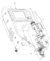
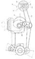
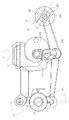
本発明一実施例の組立て位置の模式図、外観模式図、構造分解模式図である図1、2、3に示すように、本発明ミシンのダイレクトドライブ布送り機構は、ミシン100内に配置する。ミシンのダイレクトドライブ布送り機構は、布送り構造1、垂直駆動構造2、方向調整構造3を備える。布送り構造1は、スイング軸棒11、スイング軸棒11上に可動状に設置し、スイング軸棒11の連動を受ける布送り歯12を備える。垂直駆動構造2は、布送り歯12を連接し、駆動モーター(図示なし)の駆動を受けるエキセントリックロッド21、及びエキセントリックロッド21上に設置し、エキセントリックロッド21の連動を受けて回転するエキセントリックカム22を備える。駆動モーターは、エキセントリックロッド21の上方に設置し、ベルトを通して伝動し、エキセントリックロッド21の回転を駆動する。方向調整構造3は、ステップモーター31、ステップモーター31の駆動を受ける調節部32を備える。調節部32は、ステップモーター31上に可動状に接続するシャフト321、ステップモーター31の駆動を受け回転し、第一位置A1と第二位置A2を切り換えるシャフト321、シャフト321内に設置する軌道部322、軌道部322内に設置するスライドブロック324、スイング軸棒11、エキセントリックカム22に可動状に接続し、一端はスライドブロック324と連接し、しかもエキセントリックカム22の連動を受けスイングし、スライドブロック324を連動し、軌道部322内で往復スライド移動を行う連動棒323を備える。本発明は、ステップモーター31を通して、シャフト321を直接駆動する。これにより、シャフト321は、違った角度に回転し、布送り構造1を連動して、前進或いは後退の布送り行程を行わせる。
As shown in FIGS. 1, 2, and 3 which are a schematic view of an assembly position, an external view schematic diagram, and a structural exploded schematic view of an embodiment of the present invention, the direct drive cloth feed mechanism of the sewing machine of the present invention is disposed in the
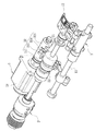
本発明の一実施例の前進布送り行程の作動模式図である図4に示すように、エキセントリックロッド21は、エキセントリックカム22を貫通し、駆動モーターの駆動を受け回転する主棒211、布送り歯12と可動状に接続する連接部212、主棒211一端にエキセントリックに設置し、連接部212と連接し、主棒211の連動を受ける副棒213を備える。主棒211は常態的に、駆動モーターの駆動を受け、時計回り/逆時計回りの回転を維持する。エキセントリックに設置する副棒213は、主棒211の連動を受け回転し、連接部212を通して、布送り歯12を連動する。これにより、布送り歯12に垂直方向の駆動力を提供し、こうして布送り歯12は、垂直往復移動を行う。垂直方向と、主棒211縦方向断面の円形の中心線とは同軸である。ステップモーター31が、シャフト321を駆動し、シャフト321が第一位置A1に位置すると、軌道部322は、ある傾斜角度を備え、エキセントリックカム22は、主棒211の連動上回転し、同時に連動棒323を連想し、スライドブロック324を引いて動かし、軌道部322内で往復スライド移動を行わせる。こうして、第一スイング行程を行う。
連動棒323は、スイング軸棒11上に可動状に接続するため、連動棒323が第一スイング行程を行うと、スイング軸棒11は、連動棒323の連動を受け、往復スイングを行う。こうして、布送り歯12を連動し、水平往復移動を行わせる。よって、布送り歯12は、連動棒323が第一スイング行程を行う時、往復スイングし、中心線片側において、水平往復移動を行い、垂直往復移動に対応して、前進布送り行程を形成する。
As shown in FIG. 4 which is an operation schematic diagram of the forward cloth feed process of one embodiment of the present invention, the
Since the
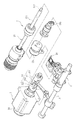
本発明の一実施例の後退布送り行程の作動模式図である図5に示すように、ステップモーター31はさらに、コントロールユニット(図示なし)と連接する。コントロールユニットは、スイッチ、コントロールインターフェース、或いはリモコン装置である。コントロールユニットを通して、コントロール信号を、ステップモーター31に伝送する。これにより、ステップモーター31は、調節部32のシャフトをダイレクトに駆動し、第二位置A2へと角度の回転を行わせる。
しかも、コントロールユニットは、自動モードと手動モードを備えることができる。
自動モードである時には、ステップモーター31は、所定の条件(ミシン縫い時間、ミシン縫い針数など)が満たされると、シャフト321の回転を駆動する。手動モードである時には、ミシン縫いの状況に応じて、いつステップモーター31を駆動するかを、使用者は自身で決定することができる。シャフト321が、ステップモーター31の駆動受け、第二位置A2まで角度を回転すると、軌道部322の傾斜角度も、それに従い変化する。こうして、スライドブロック324の往復スライド角度を改変し、連動棒323を連動して、第二スイング行程を行わせる。
連動棒323のスイング方式は、第一スイング行程から、第二スイング行程へと変る時、スイング軸棒11は、連動棒323の連動受け、スイング角度を変える。こうして、布送り歯12を連動し、布送り歯12が行う水平往復移動の位置を改変する。さらに、連動棒323が第二スイング行程を行う時、布送り歯12は、中心線の反対側で往復スイングし、水平往復移動を行う。この時、主棒211は、駆動モーターの駆動を受け、同一方向の回転を維持する。エキセントリック設置の副棒213は、主棒211の連動を受けて回転を続け、連接部212を通して布送り歯12を連動する。これにより、布送り歯12に垂直方向の駆動力を提供し、垂直往復移動を行わせ、中心線の反対側の水平往復移動に、垂直往復移動が加わり、後退布送り行程が形成される。
As shown in FIG. 5 which is a schematic diagram of the operation of the reverse cloth feeding process of one embodiment of the present invention, the
Moreover, the control unit can have an automatic mode and a manual mode.
When in the automatic mode, the
When the swing method of the interlocking
この他、本発明のステップモーター31は、シャフト321の回転角度を正確にコントロールするため、シャフト321の回転角度の調整を通して、スライドブロック324を調整し、軌道部322中で往復スライド移動行程を行わせる。シャフト321回転角度が大きくなればなるほど、つまり軌道部322の傾斜が大きくなればなるほど、スライドブロック324が、軌道部322内において往復スライド移動する行程は、より短くなる。これにより、布送り歯12が布を送る速度が速くなり、ミシン縫いの速度が相同であれば、ミシン100のミシン針(図示なし)が、布上において縫いだす針目は小さくなる。反対に、シャフト321の回転角度が小さくなればなるほど、スライドブロック324が、軌道部322内で往復スライド移動する行程はより長くなる。こうして、布送り歯12が布を送る速度は遅くなり、ミシン縫いの速度が相同であれば、ミシン100のミシン針が、布上において縫いだす針目は大きくなる。これにより、本発明は、ステップモーター31を通して、ミシン100の針目をコントロールできる。従来のミシンでは、ダイヤルを通して針目の切換を行う必要があったが、本発明は上記したように、ミシンの使用方式を簡単にすることができる。
In addition, the
本発明のステップモーター31はさらに、シャフト321を駆動して、第一位置A1と第二位置A2との間に位置する第三位置A3まで回転させることができる。具体的には、第三位置A3は起点である。シャフト321が、第三位置A3に位置する時、エキセントリックカム22が連動棒323を連動して行わせる運動の軌跡と、スライドブロック324が軌道部322内でスライドし、連動棒323を連動して行わせる運動の軌跡は、相互に相殺される。これにより、連動棒323は、スイング軸棒11の回転を連動しない。こうして、布送り歯12は、静止状態となる。ステップモーター31は、シャフト321を自由にコントロールし、第一位置A1、第二位置A2、第三位置A3において切換ることができ、布送り歯12の、布送り行程の前進、後退、静止をコントロールすることができる。
The
本発明はステップモーター31を通して、調節部32のシャフト321をダイレクトに連動する。これにより、シャフト321は回転し、第一位置A1か第二位置A2へと切り換えられ、連動棒323の進行軌道を改変することができ、こうして、第一スイング行程と第二スイング行程を行う。連動棒323は、進行軌道の違いにより、布送り歯12が水平往復移動を行う位置を改変し、さらにエキセントリックロッド21が提供する垂直往復移動の駆動力を対応させて、布送り歯12に、前進と後退の2種の布送り行程を行わせることができる。
よって、電磁石を通して複数の連棒を連接しなければシャフトをコントロールできない従来のミシンの布送り機構とは異なる。本発明は、ステップモーター31により、シャフト321をダイレクトに駆動し、シャフト321の回転角度を正確にコントロールすることができる。これにより、調節時の正確性を拡大し、さらにステップモーター31を通して、ミシン100の針目を直接コントロールするため、ミシンによる縫製の品質を向上させることができる。
In the present invention, the
Therefore, this is different from a conventional sewing machine cloth feed mechanism in which a shaft cannot be controlled unless a plurality of connecting rods are connected through an electromagnet. In the present invention, the
100 ミシン
1 布送り構造
11 スイング軸棒
12 布送り歯
2 垂直駆動構造
21 エキセントリックロッド
211 主棒
212 連接部
213 副棒
22 エキセントリックカム
3 方向調整構造
31 ステップモーター
32 調節部
321 シャフト
322 軌道部
323 連動棒
324 スライドブロック
A1 第一位置
A2 第二位置
A3 第三位置
100 Sewing machine 1
A1 First position
A2 Second position
A3 Third position
Claims (2)
前記布送り構造は、スイング軸棒、前記スイング軸棒上に可動状に設置し、前記スイング軸棒の連動を受け、水平往復移動を行う布送り歯を備え、
前記垂直駆動構造は、前記布送り歯を連接し、駆動モーターの駆動を受け、前記布送り歯に垂直往復移動を行わせるエキセントリックロッド、及び前記エキセントリックロッド上に設置し、前記エキセントリックロッドの連動を受けて回転するエキセントリックカムを備え、
前記方向調整構造は、ステップモーター、前記ステップモーターの駆動を受ける調節部を備え、
前記調節部は、前記ステップモーター上に可動状に接続し、前記ステップモーターの駆動を受け回転し、第一位置と第二位置を切り換えするシャフト、前記シャフト内に設置する軌道部、前記軌道部内に設置するスライドブロック、前記スイング軸棒、前記エキセントリックカムに可動状に接続し、一端は前記スライドブロックと連接する連動棒を備え、 前記連動棒は、前記エキセントリックカムの連動を受け、前記シャフトが第一位置と第二位置に切り換える時、第一スイング行程と第二スイング行程を行わせ、前記スライドブロックを連動し、前記軌道部内において往復スライド移動を行い、
前記布送り歯は、前記連動棒が第一スイング行程を行う時、前進布送り行程を行い、前記連動棒が第二スイング行程を行う時、後退前進布送り行程を行うことを特徴とするミシンのダイレクトドライブ布送り機構。 The direct drive cloth feed mechanism of the sewing machine has a cloth feed structure, a vertical drive structure, and a direction adjustment structure.
The cloth feed structure includes a swing feed bar that is installed in a movable manner on a swing shaft bar, the swing shaft bar, and that receives the interlock of the swing shaft bar and performs horizontal reciprocation.
The vertical drive structure is connected to the cloth feed dog, is installed on the eccentric rod that receives the drive of the drive motor and causes the cloth feed dog to perform vertical reciprocating movement, and the eccentric rod is interlocked. Equipped with an eccentric cam that receives and rotates,
The direction adjustment structure includes a step motor, an adjustment unit that receives driving of the step motor,
The adjustment unit is movably connected to the step motor, rotates by receiving the drive of the step motor, switches between a first position and a second position, a track unit installed in the shaft, The slide block installed on the swing shaft, the swing shaft rod, and the eccentric cam are movably connected, one end is provided with an interlocking rod connected to the slide block, the interlocking rod is interlocked with the eccentric cam, the shaft is When switching between the first position and the second position, the first swing stroke and the second swing stroke are performed, the slide block is interlocked, and the reciprocating slide movement is performed in the track portion.
The cloth feed dog performs a forward cloth feed stroke when the interlocking rod performs a first swing stroke, and performs a backward advance cloth feed stroke when the interlocking rod performs a second swing stroke. Direct drive cloth feed mechanism.
Priority Applications (1)
| Application Number | Priority Date | Filing Date | Title |
|---|---|---|---|
| JP2013212099A JP2015073742A (en) | 2013-10-09 | 2013-10-09 | Direct drive cloth feed mechanism for sewing machine |
Applications Claiming Priority (1)
| Application Number | Priority Date | Filing Date | Title |
|---|---|---|---|
| JP2013212099A JP2015073742A (en) | 2013-10-09 | 2013-10-09 | Direct drive cloth feed mechanism for sewing machine |
Related Child Applications (1)
| Application Number | Title | Priority Date | Filing Date |
|---|---|---|---|
| JP2015005447U Continuation JP3202791U (en) | 2015-10-27 | 2015-10-27 | Sewing machine direct drive cloth feed mechanism |
Publications (1)
| Publication Number | Publication Date |
|---|---|
| JP2015073742A true JP2015073742A (en) | 2015-04-20 |
Family
ID=52999069
Family Applications (1)
| Application Number | Title | Priority Date | Filing Date |
|---|---|---|---|
| JP2013212099A Pending JP2015073742A (en) | 2013-10-09 | 2013-10-09 | Direct drive cloth feed mechanism for sewing machine |
Country Status (1)
| Country | Link |
|---|---|
| JP (1) | JP2015073742A (en) |
Cited By (8)
| Publication number | Priority date | Publication date | Assignee | Title |
|---|---|---|---|---|
| CN105155142A (en) * | 2015-09-30 | 2015-12-16 | 杰克缝纫机股份有限公司 | Double-motor drive feed mechanism and sewing machine |
| DE102017220001A1 (en) | 2016-12-15 | 2018-06-21 | Hyundai Motor Company | METHOD FOR CONTROLLING THE INJECTION VALVE OF A VEHICLE |
| CN108286133A (en) * | 2018-03-23 | 2018-07-17 | 浙江美机缝纫机有限公司 | The close joint device of sewing machine |
| CN109930304A (en) * | 2019-04-02 | 2019-06-25 | 浙江美机缝纫机有限公司 | A kind of needle gage regulating mechanism of sewing machine |
| CN110923964A (en) * | 2019-12-27 | 2020-03-27 | 杰克缝纫机股份有限公司 | Needle pitch adjusting mechanism based on arc stepping motor and sewing machine |
| CN115182104A (en) * | 2021-04-02 | 2022-10-14 | 杰克科技股份有限公司 | Feeding thread hooking mechanism capable of being flexibly adjusted and sewing machine |
| CN115369576A (en) * | 2021-05-18 | 2022-11-22 | 琦星智能科技股份有限公司 | Sewing machine without swing seat |
| WO2022242094A1 (en) * | 2021-05-18 | 2022-11-24 | 琦星智能科技股份有限公司 | Sewing machine |
Citations (2)
| Publication number | Priority date | Publication date | Assignee | Title |
|---|---|---|---|---|
| JPS63230191A (en) * | 1987-03-19 | 1988-09-26 | ジューキ株式会社 | Regulator for feed of cloth of sewing machine |
| JP2006141547A (en) * | 2004-11-17 | 2006-06-08 | Juki Corp | Sewing machine feeder |
-
2013
- 2013-10-09 JP JP2013212099A patent/JP2015073742A/en active Pending
Patent Citations (2)
| Publication number | Priority date | Publication date | Assignee | Title |
|---|---|---|---|---|
| JPS63230191A (en) * | 1987-03-19 | 1988-09-26 | ジューキ株式会社 | Regulator for feed of cloth of sewing machine |
| JP2006141547A (en) * | 2004-11-17 | 2006-06-08 | Juki Corp | Sewing machine feeder |
Cited By (10)
| Publication number | Priority date | Publication date | Assignee | Title |
|---|---|---|---|---|
| CN105155142A (en) * | 2015-09-30 | 2015-12-16 | 杰克缝纫机股份有限公司 | Double-motor drive feed mechanism and sewing machine |
| DE102017220001A1 (en) | 2016-12-15 | 2018-06-21 | Hyundai Motor Company | METHOD FOR CONTROLLING THE INJECTION VALVE OF A VEHICLE |
| CN108286133A (en) * | 2018-03-23 | 2018-07-17 | 浙江美机缝纫机有限公司 | The close joint device of sewing machine |
| CN109930304A (en) * | 2019-04-02 | 2019-06-25 | 浙江美机缝纫机有限公司 | A kind of needle gage regulating mechanism of sewing machine |
| CN109930304B (en) * | 2019-04-02 | 2024-04-19 | 美机科技集团有限公司 | Needle distance adjusting mechanism of sewing machine |
| CN110923964A (en) * | 2019-12-27 | 2020-03-27 | 杰克缝纫机股份有限公司 | Needle pitch adjusting mechanism based on arc stepping motor and sewing machine |
| CN110923964B (en) * | 2019-12-27 | 2021-07-23 | 杰克缝纫机股份有限公司 | A needle pitch adjustment mechanism and sewing machine based on arc stepping motor |
| CN115182104A (en) * | 2021-04-02 | 2022-10-14 | 杰克科技股份有限公司 | Feeding thread hooking mechanism capable of being flexibly adjusted and sewing machine |
| CN115369576A (en) * | 2021-05-18 | 2022-11-22 | 琦星智能科技股份有限公司 | Sewing machine without swing seat |
| WO2022242094A1 (en) * | 2021-05-18 | 2022-11-24 | 琦星智能科技股份有限公司 | Sewing machine |
Similar Documents
| Publication | Publication Date | Title |
|---|---|---|
| JP2015073742A (en) | Direct drive cloth feed mechanism for sewing machine | |
| US9027488B2 (en) | Direct drive cloth feeding mechanism of sewing machine | |
| JP3202791U (en) | Sewing machine direct drive cloth feed mechanism | |
| US20210230782A1 (en) | Sewing machine | |
| CN106948101B (en) | Feeding mechanism and sewing machine | |
| JP2017184983A (en) | sewing machine | |
| JP5925603B2 (en) | sewing machine | |
| EP2228477B1 (en) | Thread cutting device for sewing machine | |
| CN108796838B (en) | Sewing machine | |
| JP2008104718A (en) | Sewing machine feed mechanism | |
| CN103469499B (en) | Fabric conveying mechanism for back tacking of sewing machine | |
| JP6166944B2 (en) | sewing machine | |
| KR102466108B1 (en) | Sewing machine with adjustable double needle distance | |
| TW201636472A (en) | Sewing machine | |
| JP2000271364A (en) | Sewing machine cloth feed mechanism | |
| CN109338603B (en) | Sewing machine reverse sewing mechanism and sewing machine | |
| TWI493083B (en) | Sewing machine direct drive feed mechanism | |
| US2562009A (en) | Reverse stitch attachment for sewing machines | |
| JP5074074B2 (en) | Sewing machine with buttons | |
| CN103835072B (en) | A kind of multi-functional width formula embroidering machine mobile frame head operating mechanism | |
| JP4509627B2 (en) | sewing machine | |
| US2579248A (en) | Sewing machine | |
| CN120520022B (en) | Sewing method of sewing machine | |
| CN118127719B (en) | A feeding mechanism for a sewing machine and a sewing machine | |
| US968329A (en) | Feed mechanism for sewing-machines. |
Legal Events
| Date | Code | Title | Description |
|---|---|---|---|
| RD02 | Notification of acceptance of power of attorney |
Free format text: JAPANESE INTERMEDIATE CODE: A7422 Effective date: 20150316 |
|
| A521 | Written amendment |
Free format text: JAPANESE INTERMEDIATE CODE: A821 Effective date: 20150317 |
|
| A02 | Decision of refusal |
Free format text: JAPANESE INTERMEDIATE CODE: A02 Effective date: 20150806 |