JP2015073728A - Cooker - Google Patents
Cooker Download PDFInfo
- Publication number
- JP2015073728A JP2015073728A JP2013211784A JP2013211784A JP2015073728A JP 2015073728 A JP2015073728 A JP 2015073728A JP 2013211784 A JP2013211784 A JP 2013211784A JP 2013211784 A JP2013211784 A JP 2013211784A JP 2015073728 A JP2015073728 A JP 2015073728A
- Authority
- JP
- Japan
- Prior art keywords
- heater
- temperature
- heating
- cooking
- distribution pattern
- Prior art date
- Legal status (The legal status is an assumption and is not a legal conclusion. Google has not performed a legal analysis and makes no representation as to the accuracy of the status listed.)
- Pending
Links
Images

Landscapes
- Electric Stoves And Ranges (AREA)
- Baking, Grill, Roasting (AREA)
Abstract
Description
本発明は、加熱調理器に関するものである。 The present invention relates to a heating cooker.
この種の加熱調理器としては、例えば単体で用いるグリル、あるいはシステムキッチンに組み込んで用いる組込式のグリルがある。いずれの方式のグリルにおいても、加熱庫の内部に上ヒーターと下ヒーターとを配置している(例えば、特許文献1参照)。 As this type of cooking device, for example, there is a grill used alone or a built-in grill used in a system kitchen. In any type of grill, an upper heater and a lower heater are arranged inside the heating chamber (see, for example, Patent Document 1).
このようなものにおいて、上ヒーターと下ヒーターとは、それぞれ一本で構成されており、その制御は、一般に庫内温度を検知するサーミスタの検知温度に基づいて加熱時間を調整することで行っている。 In such a thing, the upper heater and the lower heater are each constituted by one, and the control is generally performed by adjusting the heating time based on the temperature detected by the thermistor that detects the internal temperature. Yes.
このように、従来のグリルでは、上ヒーターと下ヒーターとの制御を庫内温度に基づいて行っている。このため、少ない量の食材の調理においては、調理に必要の無い部分の加熱まで行ってしまい、無駄な電力がかかっていた。 Thus, in the conventional grill, the upper heater and the lower heater are controlled based on the internal temperature. For this reason, in the cooking of a small amount of ingredients, heating is performed up to a portion that is not necessary for cooking, and wasteful power is applied.
また、上ヒーターと下ヒーターとがそれぞれ一本で構成されているため、部分的な火力の変更ができない。そのため、最適な加熱ができず、焼きムラが発生するという問題があった。また、ヒーター故障時には、使用できなくなるという難点があった。 Moreover, since the upper heater and the lower heater are each composed of a single piece, it is not possible to change the heating power partially. Therefore, there is a problem that optimum heating cannot be performed and uneven baking occurs. In addition, when the heater fails, there is a problem that it cannot be used.
本発明は、前記のような課題を解決するためになされたもので、調理物に合わせた加熱が行え、消費電力を抑えた省エネ調理を実現でき、ヒーター故障時に使用できなくなるのを防止できる加熱調理器を提供することを目的とする。 The present invention has been made to solve the above-described problems, and can perform heating in accordance with the food, achieve energy-saving cooking with reduced power consumption, and prevent heating from becoming unusable when a heater fails. The purpose is to provide a cooker.
本発明に係る加熱調理器は、箱形の加熱庫と、加熱庫内の上下にそれぞれ複数配置された上ヒーター及び下ヒーターと、複数の上ヒーター及び複数の下ヒーターをそれぞれ駆動させる複数の電源回路を有し、入力した調理パターン信号に基いて上ヒーター及び下ヒーターを駆動するヒーター駆動部と、加熱庫の上下左右の面の奥行き方向にそれぞれ複数配置された温度センサーと、一定火力投入時に、各温度センサーが測定した温度の温度上昇率を算出する温度上昇率判定手段と、温度上昇率判定手段が算出した各温度センサーの温度上昇率に基いて、加熱庫内の温度分布パターンを作成する温度分布パターン作成手段と、予め調理物の位置が特定された温度分布パターンのデーターが格納された温度分布パターンテーブルと、温度分布パターン作成手段が作成した温度分布パターンと温度分布パターンテーブル内の温度分布パターンデーターとを比較し、対応する温度分布パターンデーターより少なくとも調理物の位置を取得し、取得した調理物の位置と、各温度センサーの温度上昇率とに基いて、使用する上ヒーター及び下ヒーターと注入する火力と加熱時間とで構成される調理パターンを決定し、ヒーター駆動部へ調理パターン信号として出力する調理パターン決定手段と、を備えるものである。 The heating cooker according to the present invention includes a box-shaped heating chamber, a plurality of upper heaters and lower heaters arranged above and below the heating chamber, and a plurality of power sources for driving the plurality of upper heaters and the plurality of lower heaters, respectively. A heater drive unit that has a circuit and drives the upper and lower heaters based on the input cooking pattern signal, a plurality of temperature sensors arranged in the depth direction of the top, bottom, left, and right surfaces of the heating chamber, and when a constant heating power is applied The temperature rise rate determination means for calculating the temperature rise rate of the temperature measured by each temperature sensor, and the temperature distribution pattern in the heating chamber is created based on the temperature rise rate of each temperature sensor calculated by the temperature rise rate determination means Temperature distribution pattern creating means, a temperature distribution pattern table storing temperature distribution pattern data in which the position of the food is specified in advance, and a temperature distribution pattern The temperature distribution pattern created by the sample creation means and the temperature distribution pattern data in the temperature distribution pattern table are compared, and at least the position of the cooked food is obtained from the corresponding temperature distribution pattern data. A cooking pattern determining means for determining a cooking pattern composed of an upper heater and a lower heater to be used, a heating power to be injected and a heating time based on the rate of temperature rise of the temperature sensor, and outputting the cooking pattern signal to the heater driving unit Are provided.
本発明の加熱調理器においては、加熱庫内の上下に上ヒーターと下ヒーターとをそれぞれ複数配置して、これら複数の上ヒーター及び複数の下ヒーターを、複数の電源回路を有するヒーター駆動部によってそれぞれ駆動できるようにしている。また、箱形の加熱庫の上下左右の面の奥行き方向に温度センサーをそれぞれ複数配置し、一定火力投入時に、各温度センサーが測定した温度の温度上昇率を算出し、算出した各温度センサーの温度上昇率に基いて、加熱庫内の温度分布パターンを作成し、作成した温度分布パターンと予め調理物の位置が特定された温度分布パターンデーターとを比較し、対応する温度分布パターンデーターより調理物の位置を取得し、取得した調理物の位置と、各温度センサーの温度上昇率とに基いて、使用する上ヒーター及び下ヒーターと注入する火力と加熱時間とで構成される調理パターンを決定し、ヒーター駆動部へ調理パターン信号として出力し、調理物の位置に対応する上ヒーターと下ヒーターとを駆動する。このため、調理物に合わせた加熱が行え、消費電力を抑えた省エネ調理を実現できる。また、複数のヒーターのいずれかが故障しても、故障部のヒーターを補う形で、運転することができるので、修理までの延命が図れる。 In the heating cooker of the present invention, a plurality of upper heaters and lower heaters are arranged above and below the heating chamber, respectively, and the plurality of upper heaters and the plurality of lower heaters are provided by a heater driving unit having a plurality of power supply circuits. Each can be driven. In addition, multiple temperature sensors are arranged in the depth direction on the top, bottom, left, and right surfaces of the box-shaped heating chamber, and the temperature rise rate of the temperature measured by each temperature sensor is calculated when a constant heating power is applied. Based on the rate of temperature rise, create a temperature distribution pattern in the heating chamber, compare the created temperature distribution pattern with the temperature distribution pattern data in which the position of the food is specified in advance, and cook from the corresponding temperature distribution pattern data The position of the food is acquired, and based on the position of the acquired food and the temperature increase rate of each temperature sensor, the cooking pattern composed of the upper and lower heaters to be used, the heating power to be injected, and the heating time is determined. And it outputs to a heater drive part as a cooking pattern signal, and drives the upper heater and lower heater corresponding to the position of a foodstuff. For this reason, the heating according to a cooking item can be performed and the energy-saving cooking which suppressed power consumption is realizable. In addition, even if any of the plurality of heaters breaks down, the operation can be performed in a manner that supplements the heater in the failed part, so that the life until repair can be extended.
実施形態1.
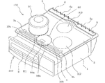
図1は本発明の実施形態1に係る加熱調理器が組み込まれたシステムキッチンの外観を示す斜視図である。図1に基づいて、本発明の加熱調理器であるグリル200が組み込まれたシステムキッチン100の構成について説明する。なお、図1には、空気の流れを矢印で表している。
FIG. 1 is a perspective view showing an appearance of a system kitchen in which a cooking device according to
システムキッチン100は、図1のようにその本体1が、上部に開口を有する矩形状箱体に形成されている。本体1の上部開口は、枠体3が取り付けられたトッププレート2によって覆われている。トッププレート2は、調理を行う際に上面に調理容器を載置するものであり、耐熱強化ガラスで構成され、その裏面には内部が見えないように印刷が施されている。また、トッププレート2の表面には、例えば、被加熱物である調理容器(たとえば、図1に示す鍋50)を加熱する位置を示す円形の加熱部H1,H2,H3が印刷等の方法で表示されている。
As shown in FIG. 1, the
トッププレート2の前側の枠体3には、上面操作部4が設けられている。その上面操作部4は、例えば加熱部H1,H2,H3にそれぞれ対応して設けられた火力設定用操作部と、グリル200の加熱を操作する操作部86aとからなっている。
An upper
トッププレート2の後ろ側の枠体3には、吸気口5と排気口6が設けられており、それぞれ複数の穴(図示せず)を有する吸気口カバー5aと排気口カバー6aとによって通気可能に覆われている。なお、吸気口5と排気口6は、本体1の背面に設けてもよいものである。
The
トッププレート2の前面側の中央部には、グリル200の動作状態や、グリル200の操作手順、動作状態等を表示する操作表示部86が設けられている。また、操作表示部86の左右には、加熱部H1,H2,H3の動作状態をそれぞれ表示する液晶表示部9a,9bと、加熱部H1,H2,H3の火力をそれぞれ表示する火力表示部10a,10bが設けられている。また、本体1の前面には、前後に移動できる扉11が設けられている。
An
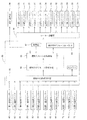
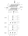
図2は本発明の実施形態1に係る加熱調理器の各上ヒーターと各下ヒーターの配置例を示す模式図である。図3は本発明の実施形態1に係る加熱調理器の操作表示部を拡大して示す平面図である。図4は本発明の実施形態1に係る加熱調理器の各上ヒーターと各下ヒーターと各温度センサーの配置例を示す模式図である。図5は本発明の実施形態1に係る加熱調理器の主要部の回路構成図である。
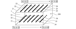
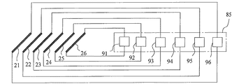
加熱調理器すなわちグリル200は、図2に示すように、上下方向よりも左右方向の寸法が大きい箱形の加熱庫7と、加熱庫7内の上下にそれぞれ複数併設されて奥行き方向に延びる上第1ヒーター21〜上第6ヒーター26と下第1ヒーター31〜下第6ヒーター36とを備えている。また、図5に示すように、入力した調理パターン信号に基いて上第1ヒーター21〜上第6ヒーター26を駆動するヒーター駆動部85を備えている。ヒーター駆動部85は、上第1ヒーター21〜上第6ヒーター26をそれぞれ独立駆動させる複数の電源回路を有しており、これら電源回路はいずれも電力可変回路91〜96で構成されている。なお、図示していないが、下第1ヒーター31〜下第6ヒーター36を駆動するヒーター駆動部85も同様に構成されている。抵抗加熱式ヒーターの電力可変回路としては、可変単巻変圧器などのトランス式のものからトライアックなどのサイリスタ素子を利用したものまで種々の形態がある。ここでは、サイリスタ位相制御を用いている。ここで、サイリスタ位相制御とは、商用の50Hzまたは60Hzの交流電源と負荷(加熱ヒーター)との間にサイリスタを接続し、点弧開始する位相を調整することによって、目的とする電力に調整し、負荷に供給する制御をいう。
FIG. 2 is a schematic diagram illustrating an arrangement example of each upper heater and each lower heater of the heating cooker according to the first embodiment of the present invention. FIG. 3 is an enlarged plan view showing the operation display unit of the cooking device according to the first embodiment of the present invention. FIG. 4 is a schematic diagram illustrating an arrangement example of each upper heater, each lower heater, and each temperature sensor of the heating cooker according to the first embodiment of the present invention. FIG. 5 is a circuit configuration diagram of the main part of the heating cooker according to the first embodiment of the present invention.
As shown in FIG. 2, the heating cooker, that is, the
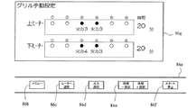
操作表示部86は、図3に示すように、操作部86aと液晶表示部86gとを有している。操作部86aには、メニューキー86b、ヒーター選択キー86c、火力選択キー86d、時間選択キー86e、スタートキー86fが設けられている。操作部86aによって、上第1ヒーター21〜上第6ヒーター26及び下第1ヒーター31〜下第6ヒーター36の中から使用するヒーターを手動で選択し、かつ注入する火力と加熱時間とを手動で設定できるようになっている。
As shown in FIG. 3, the
また、グリル200には、図4に示すように、加熱庫7の上下の面に、上第1温度センサー41〜上第3温度センサー43と下第1温度センサー51〜下第3温度センサー53が、それぞれ奥行き方向に配置されている。また、加熱庫7の左右の面に、左第1温度センサー61〜左第3温度センサー63と右第1温度センサー71〜右第3温度センサー73が、それぞれ奥行き方向に配置されている。各温度センサーは、加熱庫7内の雰囲気温度を検出するもので、例えば、サーミスタを用いる。
In addition, as shown in FIG. 4, the
図6は本発明の実施形態1に係る加熱調理器の制御装置の構成を示すブロック図である。
制御装置80は、温度上昇率判定手段81と、温度分布パターン作成手段82と、予め調理物の位置が特定された温度分布パターンのデーターが格納された温度分布パターンテーブル84と、調理パターン決定手段83と、記憶部87とを備えている。
FIG. 6 is a block diagram showing the configuration of the control device for the heating cooker according to the first embodiment of the present invention.
The
温度上昇率判定手段81は、一定火力投入時、つまり所定時間予備加熱したときに、上第1温度センサー41〜上第3温度センサー43と下第1温度センサー51〜下第3温度センサー53と左第1温度センサー61〜左第3温度センサー63と右第1温度センサー71〜右第3温度センサー73(以下、これらをまとめて「各温度センサー」という)が測定した温度の温度上昇率を算出する機能を有する。
The temperature increase rate determination means 81 is configured to apply an upper
温度分布パターン作成手段82は、温度上昇率判定手段81が算出した各温度センサーの温度上昇率に基いて、加熱庫7内の温度分布パターンを作成する機能を有する。
The temperature distribution
調理パターン決定手段83は、温度分布パターン作成手段82が作成した温度分布パターンと温度分布パターンテーブル84内の温度分布パターンデーターとを比較し、対応する温度分布パターンデーターより少なくとも調理物の位置を取得し、取得した調理物の位置と、各温度センサーの温度上昇率とに基いて、使用する上ヒーター及び下ヒーターと注入する火力と加熱時間とで構成される調理パターンを決定し、ヒーター駆動部85と液晶表示部86gへ調理パターン信号として出力する機能を有する。なお、加熱時間は調理物の温度上昇スピードによって決定され、温度上昇スピードが遅い(温度上昇率が小さい)場合は、加熱時間が長くなるように設定される。また、調理パターン決定手段83は、操作表示部86によって調理パターンが手動設定された場合には、ヒーター駆動部85と液晶表示部86gへ調理パターン信号として出力するとともに、この調理パターンを記憶部87に記憶させる機能を持っている。
The cooking pattern determining means 83 compares the temperature distribution pattern created by the temperature distribution pattern creating means 82 with the temperature distribution pattern data in the temperature distribution pattern table 84, and acquires at least the position of the cooked food from the corresponding temperature distribution pattern data. Then, based on the position of the acquired food and the temperature rise rate of each temperature sensor, a cooking pattern composed of the upper and lower heaters to be used, the heating power to be injected and the heating time is determined, and the
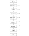
次に、本発明の実施形態1に係る加熱調理器の動作について図7及び図8に基づき図1〜図6を参照しながら説明する。図7は本発明の実施形態1に係る加熱調理器の各温度センサーのある面を展開して外側から見た各温度センサーの配置例を示す模式図である。図8は本発明の実施形態1に係る加熱調理器の自動魚焼きモード時の動作を説明するためのフローチャートである。なお、ここでは加熱庫7内に調理物である魚がセットされ、扉11が閉じられ、メニューキー86bにより自動魚焼きモードが選択されているものとする。
まず、スタートキー86fが押されると、初期火力が投入され、温度上昇率判定手段81によって各温度センサーからの温度データーの取得が開始される(ステップS1)。次いで、一定時間経過後(ステップS2)、取得した温度データーに基いて、各温度センサーが測定した温度の温度上昇率が算出され、これに基づき温度分布パターン作成手段82によって温度分布パターンが作成される(ステップS3)。ここでステップS2における一定時間とは、調理物の温度が昇温しきらない程度の時間であり、例えば3分程度である。
Next, operation | movement of the heating cooker which concerns on
First, when the start key 86f is pressed, the initial heating power is turned on, and the temperature rise rate determination means 81 starts acquiring temperature data from each temperature sensor (step S1). Next, after a lapse of a certain time (step S2), the temperature increase rate of the temperature measured by each temperature sensor is calculated based on the acquired temperature data, and a temperature distribution pattern is created by the temperature distribution pattern creating means 82 based on this. (Step S3). Here, the fixed time in step S2 is a time that the temperature of the cooked product does not fully rise, for example, about 3 minutes.
温度分布パターンは、図7に示す加熱庫7のA(上面)、B(右面)、C(下面)、及びD(左面)の各温度センサーの温度上昇率で捉える。ここで、各面における温度上昇率の大小は、各面における各温度センサーの温度上昇率の平均値で評価する。例えば、A(上面)の温度上昇率は小さい、B(右面)の温度上昇率は大きい、C(下面)の温度上昇率は小さい、D(左面)の温度上昇率は大きい、のように温度分布パターンが作成される。この温度分布パターンの場合、中心部の位置に調理物である魚が加熱庫7の奥行き方向に1尾あると判断される。
このように判断される理由は次のとおりである。温度上昇率の算出において、魚などの調理物は、初期火力投入前は冷たい状態であり、調理物に隣接する空気の温度は低い。次に、加熱を開始すると、調理物の温度はすぐに上昇しないが、調理物から離れた位置における加熱庫内の空気は、すぐに上昇する。これは、調理物よりも空気の方が比熱が小さいためである。調理物に近い位置にある温度センサーについて、この温度センサーに近接する空気の温度が上昇しにくい。この温度センサーに近接する空気の熱が調理物に伝導し、この温度センサーに近い空気の温度が上昇しにくくなるためである。一方、調理物から遠い位置にある温度センサーについては、調理物の影響を受けにくく、初期加熱投入後はすぐに温度上昇する。このように、温度センサーの温度上昇率の大小によって、温度センサーと調理物との距離の大小が検知できる。
A(上面)の温度上昇率は小さく、B(右面)の温度上昇率は大きく、C(下面)の温度上昇率は小さく、D(左面)の温度上昇率は大きいので、
(1)調理物とA(上面)の中央に配置される上第1温度センサー41〜上第3温度センサー43までの距離は小さい。
(2)調理物とB(右面)の中央に配置される右第1温度センサー71〜右第3温度センサー73までの距離は大きい。
(3)調理物とC(下面)の中央に配置される下第1温度センサー51〜下第3温度センサー53までの距離は小さい。
(4)調理物とD(左面)の中央に配置される左第1温度センサー61〜左第3温度センサー63までの距離は大きい。
従って、中心部の位置に調理物である魚が加熱庫7の奥行き方向に1尾あると判断される。
The temperature distribution pattern is captured by the temperature increase rates of the temperature sensors A (upper surface), B (right surface), C (lower surface), and D (left surface) of the
The reason for this determination is as follows. In the calculation of the rate of temperature increase, the food such as fish is in a cold state before the initial heating power is supplied, and the temperature of the air adjacent to the food is low. Next, when heating is started, the temperature of the food does not immediately increase, but the air in the heating chamber at a position away from the food immediately increases. This is because air has a lower specific heat than cooked food. About the temperature sensor in the position close to the food, the temperature of the air in the vicinity of the temperature sensor is unlikely to rise. This is because the heat of the air close to the temperature sensor is conducted to the food, and the temperature of the air close to the temperature sensor is unlikely to rise. On the other hand, the temperature sensor located far from the cooked food is not easily affected by the cooked food, and the temperature immediately rises after the initial heating. Thus, the magnitude of the distance between the temperature sensor and the food can be detected by the magnitude of the temperature rise rate of the temperature sensor.
The temperature increase rate of A (upper surface) is small, the temperature increase rate of B (right surface) is large, the temperature increase rate of C (lower surface) is small, and the temperature increase rate of D (left surface) is large.
(1) The distance from the upper
(2) The distance from the right
(3) The distance from the lower
(4) The distance from the left
Therefore, it is determined that there is one fish as a cooked food in the depth direction of the
また、A(上面)の温度上昇率は大きい、B(右面)の温度上昇率は小さい、C(下面)の温度上昇率は大きい、D(左面)の温度上昇率は大きい、のような温度分布パターンの場合は、右側の位置の1個所に調理物である魚が加熱庫7の奥行き方向に1尾あると判断される。
Moreover, the temperature rise rate of A (upper surface) is large, the temperature rise rate of B (right surface) is small, the temperature rise rate of C (lower surface) is large, and the temperature rise rate of D (left surface) is large. In the case of the distribution pattern, it is determined that there is one fish as a cooked food in the depth direction of the
また、A(上面)の温度上昇率は大きい、B(右面)の温度上昇率は大きい、C(下面)の温度上昇率は大きい、D(左面)の温度上昇率は小さい、のような温度分布パターンの場合は、左側の位置の1個所に調理物である魚が加熱庫7の奥行き方向に1尾あると判断される。
Moreover, the temperature rise rate of A (upper surface) is large, the temperature rise rate of B (right surface) is large, the temperature rise rate of C (lower surface) is large, and the temperature rise rate of D (left surface) is small. In the case of the distribution pattern, it is determined that there is one fish in the depth direction of the
また、A(上面)の温度上昇率は小さい、B(右面)の温度上昇率は小さい、C(下面)の温度上昇率は小さい、D(左面)の温度上昇率は大きい、のような温度分布パターンの場合は、中心部の位置とその右側の位置との2個所に調理物である魚が加熱庫7の奥行き方向に2尾あると判断される。
Further, the temperature rise rate of A (upper surface) is small, the temperature rise rate of B (right surface) is small, the temperature rise rate of C (lower surface) is small, and the temperature rise rate of D (left surface) is large. In the case of the distribution pattern, it is determined that there are two fish as cooked foods in the depth direction of the
また、A(上面)の温度上昇率は小さい、B(右面)の温度上昇率は大きい、C(下面)の温度上昇率は小さい、D(左面)の温度上昇率は小さい、のような温度分布パターンの場合は、中心部の位置とその左側の位置との2個所に調理物である魚が加熱庫7の奥行き方向に2尾あると判断される。
Further, the temperature rise rate of A (upper surface) is small, the temperature rise rate of B (right surface) is large, the temperature rise rate of C (lower surface) is small, and the temperature rise rate of D (left surface) is small. In the case of the distribution pattern, it is determined that there are two fish as cooked foods in the depth direction of the
また、A(上面)の温度上昇率は小さい、B(右面)の温度上昇率は小さい、C(下面)の温度上昇率は小さい、D(左面)の温度上昇率は小さい、のように、全ての面の温度上昇率が小さい温度分布パターンの場合は、中心部の位置とその左右の位置との3個所に調理物である魚が加熱庫7の奥行き方向に3尾あると判断される。
Moreover, the temperature increase rate of A (upper surface) is small, the temperature increase rate of B (right surface) is small, the temperature increase rate of C (lower surface) is small, and the temperature increase rate of D (left surface) is small. In the case of a temperature distribution pattern in which the rate of temperature increase on all surfaces is small, it is determined that there are three fish as cooked foods in the depth direction of the
また、A(上面)の温度上昇率は大きい、B(右面)の温度上昇率は大きい、C(下面)の温度上昇率は大きい、D(左面)の温度上昇率は大きい、のように、全ての面の温度上昇率が大きい温度分布パターンの場合は、加熱庫7内に調理物が無いと判断される。
Also, the temperature increase rate of A (upper surface) is large, the temperature increase rate of B (right surface) is large, the temperature increase rate of C (lower surface) is large, and the temperature increase rate of D (left surface) is large. In the case of a temperature distribution pattern in which the temperature increase rate of all surfaces is large, it is determined that there is no cooked food in the
このような温度分布パターンと調理物の位置の関係は、予め採取され、温度分布パターンデーターとして温度分布パターンテーブル84に格納されている。 Such a relationship between the temperature distribution pattern and the position of the food is collected in advance and stored in the temperature distribution pattern table 84 as temperature distribution pattern data.
ステップS3にて各温度センサーが測定した温度の温度上昇率に基いて温度分布パターンが作成されると、調理パターン決定手段83によって作成した温度分布パターンと温度分布パターンテーブル84内の温度分布パターンデーターとが比較され、対応する温度分布パターンデーターより調理物の位置が取得される。そして、取得した調理物の位置と、各温度センサーの温度上昇率とに基いて、使用する上ヒーター及び下ヒーターと注入する火力と加熱時間とで構成される調理パターンが決定され(ステップS4)、ヒーター駆動部85へ調理パターン信号として出力される。また、調理パターン決定手段83は、調理パターン信号を液晶表示部86gへも送り、図3のように液晶表示部86gに使用する上ヒーター及び下ヒーターと注入する火力と加熱時間とを表示させる。図3では使用する上ヒーター及び下ヒーターを●で示してある。ここでは、中心部の位置に調理物である魚が1尾あると判断し、使用するヒーターが、上第3ヒーター23と上第4ヒーター24、及び下第3ヒーター33と下第4ヒーター34である場合を示している。
When the temperature distribution pattern is created based on the temperature increase rate of the temperature measured by each temperature sensor in step S3, the temperature distribution pattern created by the cooking pattern determining means 83 and the temperature distribution pattern data in the temperature distribution pattern table 84 are created. And the position of the cooked food is obtained from the corresponding temperature distribution pattern data. And based on the position of the acquired cooking thing and the temperature rise rate of each temperature sensor, the cooking pattern comprised by the heating power and heating time to inject | pour the upper heater and lower heater to be used, and a heating time is determined (step S4). The cooking pattern signal is output to the
ヒーター駆動部85では、調理パターン信号の入力があると、選択された上ヒーター及び下ヒーターを、設定された火力で駆動開始し、自動調理をスタートさせる(ステップS5)。そして、規定時間が経過すると(ステップS6)、駆動した上ヒーター及び下ヒーターを停止させる。また、調理パターン決定手段83では、規定時間が経過すると、液晶表示部86g又は図示しないアラームによって自動調理が終了したことを報知させ(ステップS7)、一連の処理を終了する。
When the cooking pattern signal is input, the
また、調理パターン決定手段83は、操作表示部86によって調理パターンが手動設定された場合、ヒーター駆動部85と液晶表示部86gへ調理パターン信号として出力し、液晶表示部86gに使用する上ヒーター及び下ヒーターと注入する火力と加熱時間を表示させるとともに、このときの調理パターンを記憶部87に記憶させる。
When the cooking pattern is manually set by the
このように、本発明の実施形態1に係る加熱調理器においては、加熱庫7内の上下に複数の上第1ヒーター21〜上第6ヒーター26と複数の下第1ヒーター31〜下第6ヒーター36とを配置して、複数の電力可変回路91〜96を有するヒーター駆動部85によってそれぞれ独立駆動できるようにしている。また、箱形の加熱庫7の上下左右の面の奥行き方向に温度センサーをそれぞれ複数配置し、一定火力投入時に、各温度センサーが測定した温度の温度上昇率を算出し、算出した各温度センサーの温度上昇率に基いて、加熱庫7内の温度分布パターンを作成している。また、作成した温度分布パターンと予め調理物の位置が特定された温度分布パターンデーターとを比較し、対応する温度分布パターンデーターより調理物の位置を取得するようにしている。また、取得した調理物の位置と、各温度センサーの温度上昇率とに基いて、使用する上ヒーター及び下ヒーターと注入する火力と加熱時間とで構成される調理パターンを決定し、ヒーター駆動部85へ調理パターン信号として出力し、調理物の位置に対応する上ヒーターと下ヒーターとを駆動するようにしている。このため、調理物に合わせた加熱が行え、消費電力を抑えた省エネ調理を実現することができる。また、ヒーターのいずれかが故障しても、故障部のヒーターを補う形で、運転することができ、修理までの延命が図れる。
Thus, in the heating cooker according to the first embodiment of the present invention, a plurality of upper
また、ヒーター駆動部85は、上第1ヒーター21〜上第6ヒーター26をそれぞれ独立駆動させる電力可変回路91〜96で構成しているので、細かい火力調整ができる。このため、例えば複数のヒーターを個別に火力調整することで、均一加熱、温度分布を目的に合わせて変更することができる。
Moreover, since the
また、調理時、各温度センサーによって温度情報がフィードバックされてくるので、各温度センサーの温度情報に基いて、例えば加熱する部位、火力をコントロールすることができ、焦げすぎを防止することができる。 Moreover, since temperature information is fed back by each temperature sensor at the time of cooking, based on the temperature information of each temperature sensor, for example, a heating part and a heating power can be controlled, and an excessive burn can be prevented.
また、操作表示部86によって手動設定された調理パターンを記憶部87に記憶させるようにしているので、調理物を置く位置、サイズを使用者に合わせて更に細かく設定することができ、最適な調理を実現することができ、例えば焦げ目を付けることもできる。
In addition, since the cooking pattern manually set by the
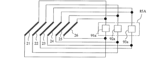
図9は本発明の実施形態1に係る加熱調理器の主要部の回路構成図の変形例である。
図9に示す例では、ヒーター2個毎に電力可変回路を有するヒーター駆動部85Aとしたものである。つまり、ヒーター駆動部85Aは、上第3ヒーター23と上第4ヒーター24とに対応する電力可変回路91aと、上第2ヒーター22と上第5ヒーター25とに対応する電力可変回路92aと、上第1ヒーター21と上第6ヒーター26とに対応する電力可変回路93aと、を備えたものである。なお、図示していないが、下第1ヒーター31〜下第6ヒーター36を駆動するヒーター駆動部85Aも同様に構成されている。
FIG. 9 is a modification of the circuit configuration diagram of the main part of the heating cooker according to the first embodiment of the present invention.
In the example shown in FIG. 9, a
一般に使用者は調理物を加熱庫7の中央部に置く。そのため、図9に示す例では、加熱庫7の中央部から左右両側へ選択的に加熱部を広げることができるようにしている。
In general, the user places the food in the center of the
このような回路構成とすることによって、回路を簡略化することができ、コストを低減することができる。 With such a circuit configuration, the circuit can be simplified and the cost can be reduced.
実施形態2.
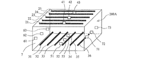
図10は本発明の実施形態2に係る加熱調理器の各上ヒーターと各下ヒーターと各温度センサーの配置例を示す模式図であり、前述の実施形態1に相当する部分には同一符号を付してある。
本発明の実施形態2に係る加熱調理器であるグリル200Aは、上第1ヒーター21〜上第5ヒーター25を横方向に延出するように配置して、上第1ヒーター21〜上第5ヒーター25と下第1ヒーター31〜下第6ヒーター36とが平面的に見て交差するようにしたものである。それ以外の構成は前述の実施形態1のものと同様である。
FIG. 10 is a schematic diagram showing an arrangement example of each upper heater, each lower heater, and each temperature sensor of the heating cooker according to the second embodiment of the present invention, and parts corresponding to the above-described first embodiment are denoted by the same reference numerals. It is attached.
The
本発明の実施形態2に係る加熱調理器であるグリル200Aにおいては、調理物の左右方向の位置に対応するように下ヒーターが選択され、調理物の奥行き方向の位置に対応するように上ヒーターが選択される。
In
各上ヒーターと各下ヒーターが同じ向きの場合、平面的に見てこれらヒーターの全てに跨がるように直交する向きに調理物(魚)が置かれると、上第1ヒーター21〜上第5ヒーター25と下第1ヒーター31〜下第6ヒーター36とが全て駆動されることになる。
When each upper heater and each lower heater are in the same direction, if the food (fish) is placed in an orthogonal direction so as to straddle all of these heaters in plan view, the upper
本発明の実施形態2に係る加熱調理器であるグリル200Aのように、上第1ヒーター21〜上第5ヒーター25と下第1ヒーター31〜下第6ヒーター36とを平面的に見て交差するように配置することで、調理物の向きに沿う側のヒーターは、調理物に対応する特定のヒーターのみ駆動すればよいため、使用電力を削減でき、省エネが図れる。
Like the
1 本体、2 トッププレート、3 枠体、4 上面操作部、5 吸気口、5a 吸気口カバー、6 排気口、6a 排気口カバー、7 加熱庫、9a,9b 液晶表示部、10a,10b 火力表示部、11 扉、21 上第1ヒーター、22 上第2ヒーター、23 上第3ヒーター、24 上第4ヒーター、25 上第5ヒーター、26 上第6ヒーター、31 下第1ヒーター、32 下第2ヒーター、33 下第3ヒーター、34 下第4ヒーター、35 下第5ヒーター、36 下第6ヒーター、41 上第1温度センサー、42 上第2温度センサー、43 上第3温度センサー、50 鍋、51 下第1温度センサー、52 下第2温度センサー、53 下第3温度センサー、61 左第1温度センサー、62 左第2温度センサー、63 左第3温度センサー、71 右第1温度センサー、72 右第2温度センサー、73 右第3温度センサー、80 制御装置、81 温度上昇率判定手段、82 温度分布パターン作成手段、83 調理パターン決定手段、84 温度分布パターンテーブル、85,85A ヒーター駆動部、86 操作表示部、86a 操作部、86b メニューキー、86c ヒーター選択キー、86d 火力選択キー、86e 時間選択キー、86f スタートキー、86g 液晶表示部、87 記憶部、91,91a,92,92a,93,93a,94,95,96 電力可変回路、100 システムキッチン、200,200A グリル(加熱調理器)、H1,H2,H3 加熱部。 DESCRIPTION OF SYMBOLS 1 Main body, 2 Top plate, 3 Frame body, 4 Upper surface operation part, 5 Intake port, 5a Inlet cover, 6 Exhaust port, 6a Exhaust port cover, 7 Heating chamber, 9a, 9b Liquid crystal display part, 10a, 10b Thermal display 11 Upper door, 21 Upper first heater, 22 Upper second heater, 23 Upper third heater, 24 Upper fourth heater, 25 Upper fifth heater, 26 Upper sixth heater, 31 Lower first heater, 32 Lower first 2 heaters, 33 lower third heater, 34 lower fourth heater, 35 lower fifth heater, 36 lower sixth heater, 41 upper first temperature sensor, 42 upper second temperature sensor, 43 upper third temperature sensor, 50 pan , 51 Lower first temperature sensor, 52 Lower second temperature sensor, 53 Lower third temperature sensor, 61 Left first temperature sensor, 62 Left second temperature sensor, 63 Left third Degree sensor, 71 Right first temperature sensor, 72 Right second temperature sensor, 73 Right third temperature sensor, 80 Control device, 81 Temperature rise rate determination means, 82 Temperature distribution pattern creation means, 83 Cooking pattern determination means, 84 Temperature Distribution pattern table, 85, 85A heater drive unit, 86 operation display unit, 86a operation unit, 86b menu key, 86c heater selection key, 86d thermal power selection key, 86e time selection key, 86f start key, 86g liquid crystal display unit, 87 storage Part, 91, 91a, 92, 92a, 93, 93a, 94, 95, 96 Electric power variable circuit, 100 system kitchen, 200, 200A grill (heating cooker), H1, H2, H3 heating part.
Claims (3)
前記加熱庫内の上下にそれぞれ複数配置された上ヒーター及び下ヒーターと、
前記複数の上ヒーター及び前記複数の下ヒーターをそれぞれ駆動させる複数の電源回路を有し、入力した調理パターン信号に基いて前記上ヒーター及び前記下ヒーターを駆動するヒーター駆動部と、
前記加熱庫の上下左右の面の奥行き方向にそれぞれ複数配置された温度センサーと、
一定火力投入時に、前記各温度センサーが測定した温度の温度上昇率を算出する温度上昇率判定手段と、
前記温度上昇率判定手段が算出した前記各温度センサーの温度上昇率に基いて、前記加熱庫内の温度分布パターンを作成する温度分布パターン作成手段と、
予め調理物の位置が特定された温度分布パターンのデーターが格納された温度分布パターンテーブルと、
前記温度分布パターン作成手段が作成した温度分布パターンと前記温度分布パターンテーブル内の温度分布パターンデーターとを比較し、対応する温度分布パターンデーターより少なくとも調理物の位置を取得し、該取得した調理物の位置と、前記各温度センサーの温度上昇率とに基いて、使用する前記上ヒーター及び前記下ヒーターと注入する火力と加熱時間とで構成される調理パターンを決定し、前記ヒーター駆動部へ調理パターン信号として出力する調理パターン決定手段と、
を備えることを特徴とする加熱調理器。 A box-shaped heating chamber;
A plurality of upper heaters and lower heaters respectively arranged above and below the heating chamber;
A plurality of power supply circuits for driving the plurality of upper heaters and the plurality of lower heaters, respectively, and a heater driving unit for driving the upper heater and the lower heater based on an input cooking pattern signal;
A plurality of temperature sensors respectively arranged in the depth direction of the upper, lower, left and right surfaces of the heating chamber;
A temperature rise rate determining means for calculating a temperature rise rate of the temperature measured by each temperature sensor when a constant heating power is applied;
Based on the temperature increase rate of each temperature sensor calculated by the temperature increase rate determining means, temperature distribution pattern creating means for creating a temperature distribution pattern in the heating chamber;
A temperature distribution pattern table storing temperature distribution pattern data in which the position of the food is specified in advance;
The temperature distribution pattern created by the temperature distribution pattern creation means is compared with the temperature distribution pattern data in the temperature distribution pattern table, and at least the position of the food is obtained from the corresponding temperature distribution pattern data, and the obtained food And a cooking pattern composed of the heating power and heating time to be injected with the upper heater and the lower heater to be used are determined based on the position of the temperature sensor and the temperature increase rate of each temperature sensor, and cooking is performed to the heater driving unit. Cooking pattern determining means for outputting as a pattern signal;
A heating cooker comprising:
Priority Applications (1)
| Application Number | Priority Date | Filing Date | Title |
|---|---|---|---|
| JP2013211784A JP2015073728A (en) | 2013-10-09 | 2013-10-09 | Cooker |
Applications Claiming Priority (1)
| Application Number | Priority Date | Filing Date | Title |
|---|---|---|---|
| JP2013211784A JP2015073728A (en) | 2013-10-09 | 2013-10-09 | Cooker |
Publications (1)
| Publication Number | Publication Date |
|---|---|
| JP2015073728A true JP2015073728A (en) | 2015-04-20 |
Family
ID=52999056
Family Applications (1)
| Application Number | Title | Priority Date | Filing Date |
|---|---|---|---|
| JP2013211784A Pending JP2015073728A (en) | 2013-10-09 | 2013-10-09 | Cooker |
Country Status (1)
| Country | Link |
|---|---|
| JP (1) | JP2015073728A (en) |
Cited By (3)
| Publication number | Priority date | Publication date | Assignee | Title |
|---|---|---|---|---|
| JP2020029986A (en) * | 2018-08-22 | 2020-02-27 | 東京瓦斯株式会社 | Cooker and control system |
| CN113334740A (en) * | 2021-06-04 | 2021-09-03 | 福建华盛铭兔环保科技有限公司 | High-efficient thermoforming food storage box production line |
| WO2025204665A1 (en) * | 2024-03-26 | 2025-10-02 | パナソニックIpマネジメント株式会社 | Heating cooker, heating method, and heating program |
-
2013
- 2013-10-09 JP JP2013211784A patent/JP2015073728A/en active Pending
Cited By (3)
| Publication number | Priority date | Publication date | Assignee | Title |
|---|---|---|---|---|
| JP2020029986A (en) * | 2018-08-22 | 2020-02-27 | 東京瓦斯株式会社 | Cooker and control system |
| CN113334740A (en) * | 2021-06-04 | 2021-09-03 | 福建华盛铭兔环保科技有限公司 | High-efficient thermoforming food storage box production line |
| WO2025204665A1 (en) * | 2024-03-26 | 2025-10-02 | パナソニックIpマネジメント株式会社 | Heating cooker, heating method, and heating program |
Similar Documents
| Publication | Publication Date | Title |
|---|---|---|
| JP6463045B2 (en) | Grill equipment | |
| JP2015073728A (en) | Cooker | |
| JP2015055382A (en) | Cooker | |
| AU2011248525B2 (en) | Energy saving food finishing appliance and method | |
| JP2017107766A (en) | Induction heating cooker | |
| JP2007311212A (en) | Induction heating cooker | |
| JP2014117448A (en) | Show case | |
| JP2013191586A (en) | Induction heating cooker | |
| JP2007309612A (en) | Cooker | |
| JP5285891B2 (en) | Induction heating cooker | |
| JP2005052445A (en) | Cooker | |
| JP2007051806A (en) | Cooker | |
| JP2016013264A (en) | Cooker | |
| JP2013050298A (en) | Cooker | |
| JP6827895B2 (en) | Induction heating cooker | |
| JP5723810B2 (en) | Cooker | |
| JP2004111161A (en) | Heating cooker | |
| JP2006004630A (en) | Heating cooker | |
| KR20080066634A (en) | Temperature regulation method for cook top | |
| JPH0956602A (en) | Hot plate | |
| JP2017172941A (en) | Stove | |
| JP2014235934A (en) | Induction heating cooker | |
| JP6060041B2 (en) | Induction heating cooker | |
| JP2013135786A (en) | Heating cooker | |
| JP6364622B2 (en) | Induction heating cooker |