JP2015072109A - Refrigerator - Google Patents
Refrigerator Download PDFInfo
- Publication number
- JP2015072109A JP2015072109A JP2014006551A JP2014006551A JP2015072109A JP 2015072109 A JP2015072109 A JP 2015072109A JP 2014006551 A JP2014006551 A JP 2014006551A JP 2014006551 A JP2014006551 A JP 2014006551A JP 2015072109 A JP2015072109 A JP 2015072109A
- Authority
- JP
- Japan
- Prior art keywords
- refrigerator
- image
- storage
- food
- display terminal
- Prior art date
- Legal status (The legal status is an assumption and is not a legal conclusion. Google has not performed a legal analysis and makes no representation as to the accuracy of the status listed.)
- Granted
Links
Images


Abstract
Description
本発明は、冷蔵室等に収納した食品の保存期間管理ができる冷蔵庫に関する。 The present invention relates to a refrigerator capable of managing the storage period of food stored in a refrigerator room or the like.
一般にこの種の冷蔵庫は数多くのものが提案されている。例えば、特許文献1に記載されている冷蔵庫及び冷蔵システムは、キーボード等の操作入力部、あるいは物品のバーコードデータを読み取るバーコードリーダ、あるいは音声認識を行うためのマイクを備えていて、これらのいずれかによって物品の賞味期限等の保存期間データを入力している。そしてこの冷蔵庫に保持されている管理情報は、ネットワークを通じて携帯電話等の端末装置で随時閲覧が可能となっている。
In general, many refrigerators of this type have been proposed. For example, a refrigerator and a refrigeration system described in
また、特許文献2に記載されている冷蔵庫及び冷蔵システムは、食品の入出庫量、滞留期間及び品質状態を観測する観測手段としてカメラを用い、このカメラで食品に表示された文字及び/又は符号から加工日、購入日、品目及び賞味期限の何れかの情報を読み取り、その保存期限を管理するようになっている。
The refrigerator and the refrigeration system described in
しかしながら、前記特許文献1に記載の構成では、使用者が操作入力部、あるいはバーコードリーダ、あるいはマイクを用いて保存期間を入力する面倒な作業が必要であり、実用的でない。
However, the configuration described in
また、特許文献2に記載のものも食料を冷蔵庫内に入れる際に当該食料に表示された文字及び/又は符号等をカメラに撮像させる必要があり、特許文献1と同様食品の収納作業が面倒なものとなって実用的でない。
In addition, in the case of the one described in
そこで本発明はこのような点に鑑みてなしたもので、カメラ等で撮像する場合の利点、すなわち画像認識技術を利用して保存期間管理できるようにしたもので、使用者に負担をかけることなく保存管理ができる使い勝手の良い冷蔵庫を提供するものである。 Therefore, the present invention has been made in view of the above points, and is advantageous in that an image is captured by a camera or the like, that is, a storage period can be managed using an image recognition technology, which places a burden on the user. It is an easy-to-use refrigerator that can be stored and managed.
本発明は上記目的を達成するため、収納室内部を撮像する撮像手段と、前記撮像手段により撮像された画像から対象物を特定する対象物特定手段と、前記対象物特定手段により特定された対象物の保存期間を記憶する保存期間記憶部と、前記対象物特定手段により特定された対象物の画像を所定時間の前後で比較する比較手段と、前記保存期間記憶部に記憶される保存期間を所定の条件下で補正する補正演算手段と、を備え、前記補正演算手段は、前記比較手段の比較結果に基づいて前記保存期間記憶部に記憶されている保存期間を変更補正する構成としてある。 In order to achieve the above-mentioned object, the present invention provides an imaging means for imaging the inside of a storage room, an object specifying means for specifying an object from an image captured by the imaging means, and an object specified by the object specifying means A storage period storage unit that stores a storage period of the object, a comparison unit that compares images of the object specified by the object specifying unit before and after a predetermined time, and a storage period stored in the storage period storage unit. Correction arithmetic means for correcting under a predetermined condition, wherein the correction arithmetic means changes and corrects the storage period stored in the storage period storage unit based on the comparison result of the comparison means.
これによりこの冷蔵庫では、対象物特定手段で特定した食品は所定時間、例えば食事や料理に供した時間後の食品と画像比較し、その画像の変化が小さい、例えば量が少なくなっている、あるいは大きさが小さくなっている等の変化を認識すれば保存期間はそのまま
とし、画像に大きな変化があれば同一食品が買い換えられて新規に入れ替わった、または特定した食品が消費されてなくなったとして保存期間を変更補正する。したがって、使用者は食品収納時に食料に表示された文字等を撮像させる手間をかけることなくただ単に収納すればよく、しかも食料が継続使用されているのか、あるいは新規に入れ替わったのかが自動的に判別されるので、食品の保存管理が確実に行える。
Thereby, in this refrigerator, the food specified by the object specifying means is compared with the food for a predetermined time, for example, after food or cooking, and the change in the image is small, for example, the amount is small, or Recognize changes such as small size, keep the storage period as it is, and if there is a big change in the image, store the same food as a new replacement or when the specified food is no longer consumed Change and correct the period. Therefore, the user can simply store the food without taking the trouble of imaging characters displayed on the food, and whether the food is continuously used or newly replaced automatically. Since the determination is made, the food storage management can be reliably performed.
本発明は、食品収納時に何ら手間をかけることなく確実な保存管理ができ、使い勝手の良い冷蔵庫を提供することができる。 INDUSTRIAL APPLICABILITY The present invention can provide reliable storage management without taking any trouble at the time of food storage and provide an easy-to-use refrigerator.
以下、本発明の具体的かつ詳細な実施の形態を説明するが、まず本発明の実施の形態の要点を記載する。 Hereinafter, specific and detailed embodiments of the present invention will be described. First, the main points of the embodiments of the present invention will be described.
本発明における冷蔵庫の実施の形態は、内箱と外箱とより構成され前面が開口した冷蔵庫本体と、前記冷蔵庫本体を仕切ることで構成される収納室と、前記収納室を覆う断熱扉と、前記収納室もしくは前記断熱扉に設けられ前記収納室の内部を撮像する撮像手段と、前記撮像手段により撮像された画像から対象物を特定する対象物特定手段と、前記対象物特定手段により特定された対象物の保存期間を記憶する保存期間記憶部と、前記対象物特定手段により特定された対象物の画像を所定時間の前後で比較する比較手段と、前記保存期間記憶部に記憶される保存期間を所定の条件下で補正する補正演算手段と、を備え、前記補正演算手段は、前記比較手段の比較結果に基づいて前記保存期間記憶部に記憶されている保存期間を変更補正する構成としてある。 An embodiment of the refrigerator in the present invention is composed of an inner box and an outer box, and a refrigerator main body having an open front surface, a storage room configured by partitioning the refrigerator main body, a heat insulating door that covers the storage room, An imaging unit that is provided in the storage chamber or the heat insulating door and images the inside of the storage chamber, an object specifying unit that specifies an object from an image captured by the imaging unit, and an object specifying unit A storage period storage unit that stores a storage period of the target object, a comparison unit that compares images of the target object specified by the target object specifying unit before and after a predetermined time, and a storage stored in the storage period storage unit Correction calculating means for correcting the period under a predetermined condition, and the correction calculating means changes and corrects the storage period stored in the storage period storage unit based on the comparison result of the comparison means. There as.
これによりこの冷蔵庫では、対象物特定手段で特定した食品は所定時間、例えば食事や料理に供した時間後の食品と画像比較し、その画像の変化が小さい、例えば量が少なくなっている、あるいは大きさが小さくなっている等の変化を認識すれば保存期間はそのままとし、画像に大きな変化があれば同一食品が買い換えられて新規に入れ替わった、または特定した食品が消費されてなくなったとして保存期間を変更補正する。したがって、使用者は食品収納時に食料に表示された文字等を撮像させる手間をかけることなくただ単に収納すればよく、しかも食料が継続使用されているのか、あるいは新規に入れ替わったのかが自動的に判別されるので、食品の保存管理が確実に行える。 Thereby, in this refrigerator, the food specified by the object specifying means is compared with the food for a predetermined time, for example, after food or cooking, and the change in the image is small, for example, the amount is small, or Recognize changes such as small size, keep the storage period as it is, and if there is a big change in the image, store the same food as a new replacement or when the specified food is no longer consumed Change and correct the period. Therefore, the user can simply store the food without taking the trouble of imaging characters displayed on the food, and whether the food is continuously used or newly replaced automatically. Since the determination is made, the food storage management can be reliably performed.
また、前記比較手段の比較結果において、今回の画像の対象物の大きさが前回の画像の対象物の大きさよりも大きいと判断されたときには、前記補正演算手段は、前記保存期間を再設定する構成としてある。 Further, when it is determined in the comparison result of the comparison means that the size of the object of the current image is larger than the size of the object of the previous image, the correction calculation means resets the storage period. As a configuration.
これにより、食事に供して小さくなる特性の食品が大きくなるということは当該食品が継続使用食品ではなく新規に入れ替えられた食品であることを認識してその保存期間をリセットし再設定するので、同一食品であっても継続使用食品と新規入れ替え食品を見分けてそれぞれに対応して保存期間を管理することができる。 As a result, the fact that foods with characteristics that become smaller for meals become larger means that the food is not a continuous use food but a newly replaced food, so the storage period is reset and reset, Even for the same food, it is possible to distinguish between continuously used foods and newly replaced foods and to manage the storage period corresponding to each.
さらに、前記比較手段の比較結果において、対象物の不在期間が所定時間よりも長い場
合には、前記補正演算手段は、前記保存期間を再設定する構成としてある。
Furthermore, in the comparison result of the comparison means, when the absence period of the object is longer than a predetermined time, the correction calculation means is configured to reset the storage period.
これにより、対象物の不在期間が所定時間、例えば食事や料理をする時間よりも長い場合には当該食品は買い出しによって新たに入れ替えられたものと判断しその保存期間をリセットして再設定するので、同一食品であっても継続使用食品と新規入れ替え食品を見分けてそれぞれに対応して保存期間を管理することができる。 As a result, if the absence period of the object is longer than a predetermined time, for example, the time to eat or cook, the food is judged to be newly replaced by purchase, and the storage period is reset and reset. Even for the same food, it is possible to distinguish between continuously used foods and newly replaced foods and to manage the storage period corresponding to each.
また、前記対象物特定手段は、前記撮像手段により撮像された画像における対象物の特異点に基づいて対象物を特定する構成としてある。 The object specifying unit is configured to specify the object based on a singular point of the object in the image captured by the image capturing unit.
これにより、食品の収納位置が出し入れのたびに変わっても対象物を正確に特定することができ、精度の高い保存管理が可能となる。 As a result, even when the food storage position changes each time the food is taken in and out, the object can be accurately specified, and high-precision storage management is possible.
また、前記特異点は、対象物の色相である構成としてある。 Further, the singular point is configured to be the hue of the object.
これにより、各食品の細かな違いを正確に判別することができ、更に精度の高い保存管理が可能となる。 Thereby, the fine difference of each foodstuff can be discriminate | determined correctly, and also highly accurate preservation | save management is attained.
以下、本発明の実施の形態1について、図面を用いて説明する。尚、本発明は小型カメラ等で撮像した冷蔵庫内の食品収納状況を、インターネット回線を介してスマートフォン等の表示端末により確認できるようにした冷蔵庫およびその冷蔵庫システムに適用した場合を例にして説明するが、これによって本発明が限定されるものではない。
[実施の形態1]
<1.構成>
1−1.冷蔵庫の構成
1−1−1.フレンチドアタイプの冷蔵庫の構成
図1〜図9を用いてフレンチドアタイプの冷蔵庫の場合の構成例についてまず説明する。
[Embodiment 1]
<1. Configuration>
1-1. Configuration of refrigerator 1-1-1. Configuration of French Door Type Refrigerator First, a configuration example in the case of a French door type refrigerator will be described with reference to FIGS.
図1〜図3において、冷蔵庫本体1は、前方に開口する金属製(例えば鉄板)の外箱2と、硬質樹脂製(例えばABS)の内箱3と、これら外箱2と内箱3との間に発泡充填した硬質発泡ウレタン等の断熱材4からなる。上記冷蔵庫本体1はその内部に複数の収納室を仕切形成してある。この収納室は、冷蔵庫本体1の上部から、冷蔵室5、冷蔵室5の下に位置する切替室6及び切替室6に並設した製氷室7、切替室6及び製氷室7の下部に位置する冷凍室8と、冷凍室8の下部に位置する野菜室9となっている。また、前記冷蔵室5の前面は、観音開き式の扉10により開閉自由に閉塞し、切替室6及び製氷室7と冷凍室8と野菜室9の前面部は引き出し式の扉11,12,13,14(以下、引き出し式扉と称す)によって開閉自由に閉塞してある。
1 to 3, the
冷蔵庫本体1の背面には冷却室16があり、冷気を生成する冷却器17と、冷気を各室に供給する送風ファン18と、冷蔵室への風量を調整するためのダンパ(風量調整手段)22とが設けてある。また、上記冷蔵庫本体1の本体天面奥部にはコンプレッサ19が設けてあり、コンデンサ(図示せず)と、放熱用の放熱パイプ20と、キャピラリーチューブ21と、前記した冷却器17とを順次環状に接続してなる冷凍サイクルに冷媒を封入し、冷却運転を行うように構成してある。
There is a
ここで、上記各扉10〜14は冷蔵庫本体1と同様硬質発泡ウレタンを充填して断熱性を持たせてあり、この冷蔵庫では、上記扉10〜14のうち、冷蔵室となる収納室5の扉10の一方の前面に表示手段としての表示端末15が装備してある。この表示端末15は
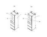
後述するインターネット等と通信可能なスマートフォン、タブレットPC等で形成し、液晶パネル等のディスプレイ部とそれを制御する制御部を一体に有していて、図4(a)に示すように扉10に一体的に取付けたり、あるいは、図4(b)に示すように扉10に着脱自在としてあり、いずれかの方式で装備させてある。
Here, each said door 10-14 is filled with hard foaming urethane similarly to the refrigerator
図5(a)、(b)は扉10に対する表示端末15の装着構成例を示し、図5(a)は表示端末15を一体的に取り付けた場合、図5(b)は表示端末15を着脱自在に装着した場合を示す。
5 (a) and 5 (b) show examples of the configuration of mounting the
図5(a)、(b)において、扉10は、主に、冷蔵庫の前面側に面する外被パネル10aと、冷蔵庫の庫内側に面する内側板10bと、外被パネル10aと内側板10bとの間に充填した断熱材4とで構成してある。外被パネル10aはカラー鋼板などの金属製の部材或いはガラス板等の透明の部材で構成してあり、内側板10bは真空成型により形成した合成樹脂部材である。内側板10bの周囲部分には、庫内側から見てロの字状で庫内側に突出する隆起壁部10b−1が設けてある。また、断熱材4にはすでに述べたように例えば硬質発泡ウレタンなどが用いてある。
5 (a) and 5 (b), the
また、表示端末15を一体化した図5(a)の扉10においては、扉10の前面側に、外被パネル10aと連続して断熱材4を覆う樹脂製の収納枠体23が設けてある(外被パネル10aがガラス板である場合はガラス板に一体的に接着して設けてある)。表示端末15は、端末保持体24を介して収納枠体23に固定されている。また、表示端末15の前面側には、タッチパネル25を設けている。表示端末15とタッチパネル25間は隙間26が設けてあり、表示端末15からのノイズによってタッチパネル25が誤作動を起さないようにしてある。表示端末15、タッチパネル25はその外周縁を覆う枠体27を扉10表面に取り付けて固定してある。このように、収納枠体23を設けることで、断熱材4が表示端末15に直接ふれることがないため、断熱材4を発泡する際に、表示端末15が高温に曝されたり、変形したりするなどの不具合を防止することができる。一方、表示端末15を着脱自在とした図5(b)の扉10では、扉10の前面部に収納枠体23を設けることで、凹部28を形成し、この凹部28に表示端末15を着脱するように構成してある。
Further, in the
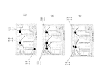
図6(a)、(b)、(c)は、扉10と表示端末15のディスプレイ透視構成の一例を示し、図6(a)、(b)は扉10の外被パネル10aがガラス板10a−1の場合、図3(c)は扉10の外被パネル10aをマジックミラー10a−2で構成した場合を示す。
6A, 6B, and 6C show an example of a display see-through configuration of the
図6(a)においては、扉10に埋設した表示端末15とガラス板10a−1との間に、表示端末15と対向する部分のみ透明としたスモークシート29が設けてあり、表示端末15がオフで黒っぽく見える時でも、表示端末15以外のガラス板10a−1部分もスモークシート29によって黒っぽく見えて表示端末15との境界が目立つことがなくなり、外観を良好に維持することができる。また、図6(b)においては、表示端末15の表示部として透明液晶表示部を用い全体が黒いスモークシート29aを透明液晶表示部の裏面に沿うように敷設したもので、この形態によっても外観を良好なものとすることができる。更に、図6(c)では図6(a)、(b)のガラス板10a−1をマジックミラー10a−2とし、スモークシート29を不要としたもので、この場合も外観を良好に維持することができる。いずれも表示端末15を扉10に一体的に取り付けた場合の例を示す。なお、スモークシート29の代わりにガラス板10a−1の背面側に黒っぽく見えるよう塗装を行ってもよい。
In FIG. 6A, a
図7、図8(a)、(b)は庫内撮像用のカメラと庫内照明灯の取り付け例を示すもの
で、図7は扉を閉じた状態の冷蔵庫の縦断面図、図8(a)は同扉を閉じた状態の冷蔵庫における扉内面部を示す横断面図、図8(b)は同扉を開いたときの扉内面部の正面図である。
FIGS. 7, 8 (a) and 8 (b) show an example of mounting of a camera for interior imaging and interior lighting, and FIG. 7 is a longitudinal sectional view of the refrigerator with the door closed, FIG. a) is a cross-sectional view showing the inner surface of the door in the refrigerator with the door closed, and FIG. 8B is a front view of the inner surface of the door when the door is opened.
図7、図8(a)、(b)において、冷蔵庫の収納室5には上下複数段に棚板30−1〜30−4が設けてある。この棚板30−1〜30−4は周囲の枠を除き、透明な合成樹脂材やガラスなどの透過性を有する材料で形成してある。
7, 8 (a), and 8 (b), the
31は最下段の棚板30−4の下方に引き出し自在に設けた収納容器である。最下段の棚板30−4は収納容器31の上面を構成することから固定されているものの、棚板30−1〜30−3は、それぞれ収納室5の両側壁部に設けられた側壁凸部32−1〜32−4に載せられており、脱着自在となっている。特に、最下段の棚板30−4を除いた棚板30−1〜30−3のうち中央の棚板30−2には、対応する側壁凸部32−2が異なる高さに複数、設けられており、棚の高さを調節できるようになっている。
33−1〜33−3は前記収納室5の開口を開閉する扉10の内面部に設けた扉ポケットで、上下複数段設けてある。この扉ポケット33−1〜33−3も透過性を有する材料で形成してある。
33-1 to 33-3 are door pockets provided on the inner surface of the
34−1,34−2は庫内照明灯で、前記各棚板30−1〜30−4の前端より前方の前記収納室5の前面開口両側壁部と前面開口上面壁面部に設けてある。なお、この庫内照明灯34−1,34−2は省エネの関係から複数のLEDを配置した基板を例えば上下方向に渡り設けて透光性のカバーで覆ってある。
34-1 and 34-2 are interior lighting lamps provided on the front opening both side walls and the front opening upper wall surface of the
35−1,35−2は前記庫内照明灯34−1,34−2と同様収納室5の前面側に位置するように設けた撮像手段としてのカメラで、例えば、CCDカメラやCMOSカメラ等で構成してあり、その種類は特に限定するものではないが、結露等に強いものであるのが好ましい。
Reference numerals 35-1 and 35-2 denote cameras as imaging means provided so as to be located on the front side of the
この実施の形態では前記カメラ及び温度状態確認手段(以下、サーモカメラと称す)は二つ設けてあって、その一方35−1は上段扉ポケット33−1の前後方向略中央の下面に取り付けてあり、もう一方35−2は最下段の扉ポケット33−3の上部付近に取り付けてある。ここで、扉ポケット33の前後方向とは、扉10の内側板10bが構成する面に対して垂直方向であり、扉10を閉じた際には収納室5の前後方向と同一となる方向である。
In this embodiment, there are two cameras and temperature state confirmation means (hereinafter referred to as a thermo camera), one of which is attached to the lower surface of the upper door pocket 33-1 in the front-rear direction substantially in the center. Yes, the other 35-2 is attached near the upper part of the lowermost door pocket 33-3. Here, the front-rear direction of the
また、上方のカメラ35−1は最上段の棚板30−1の略前方位置に、下方のカメラ35−2は図中三段目の棚板30−3の前方位置に設けてある。つまり、いずれのカメラも、高さ調節を前提にして設けられている複数の側壁凸部32−2に載せられる棚板30−2ではなく、脱着可能ではあるが高さ調整を前提としていない棚板30−1、棚板30−3の略前方位置に設けてある。 Further, the upper camera 35-1 is provided at a position substantially in front of the uppermost shelf 30-1, and the lower camera 35-2 is provided at a position in front of the third shelf 30-3 in the drawing. In other words, each camera is not a shelf 30-2 placed on a plurality of side wall projections 32-2 provided on the premise of height adjustment, but a shelf that is detachable but is not premised on height adjustment. It is provided at a substantially forward position of the plate 30-1 and the shelf plate 30-3.
そして、いずれのカメラ35−1,35−2も、図7から明らかなように各棚板30−1〜30−4の前端より前方位置であって、かつ、図8(b)に示す様に扉10の軸支部Xとは反対の開放端側端部Y付近、すなわち冷蔵庫51の左右方向の略中央部に位置するように設けて、この二つのカメラ35−1,35−2で庫内のほぼ全域が撮像できるようにしてある。このフレンチドアの例の場合、カメラ35−1,35−2は大きい面積の扉10側に設けて、冷蔵庫51の略中央部に位置するように設定してある。また、この例では、カメラ35−1,35−2はセンターピラー36(図3参照)が設けられていない扉10側に設けて、冷蔵庫51の略中央部に位置するように設定してある。なお、センター
ピラー36とは、周知の如くフレンチドアの場合に、2枚の扉10のいずれか一方の側面に設けられ、2枚の扉10の間に生じる隙間から収納室5内の冷気が漏れるのを防止するために設けられた部材である。
As is clear from FIG. 7, both the cameras 35-1 and 35-2 are positioned forward from the front ends of the shelf boards 30-1 to 30-4, and as shown in FIG. 8B. Are provided in the vicinity of the open end side end Y opposite to the shaft support X of the
なお、カメラ35−1,35−2、37−1,37−2は、図9の(a)に示すように収納容器内専用のカメラ35−3を追加設置したり、同図(b)のように、下方のカメラ35−2を上下動自在に設けたり、同図(c)のように、下方のカメラ35−2を上下方向に回動自在に設けたりと、設置する冷蔵庫の形態に応じて任意に設定すればよい。 For the cameras 35-1, 35-2, 37-1, 37-2, as shown in FIG. 9A, a camera 35-3 dedicated to the inside of the storage container is additionally installed, or FIG. The lower camera 35-2 can be moved up and down as shown in the figure, or the lower camera 35-2 can be turned up and down as shown in FIG. It may be set arbitrarily according to the above.
また、前記庫内照明灯34−1,34−2は、図7から明らかなようにカメラ35−1,35−2より収納室奥側の位置に設け、庫内照明灯34−1,34−2の光が直接カメラ35−1,35−2の撮像部に入り込まないように設けてある。 Further, as is apparent from FIG. 7, the interior lamps 34-1 and 34-2 are provided at positions on the far side of the storage room from the cameras 35-1 and 35-2, and the interior lamps 34-1 and 34 are provided. -2 light is provided so that it does not directly enter the imaging sections of the cameras 35-1 and 35-2.
より具体的には、図8(a)に示すように、カメラ35−1,35−2の撮像部は、庫内照明灯34−1,34−2の照射方向の照射量(最大照射量)に対し照射量が1/2以上となる範囲、この例では、照射角60度の範囲の外に設けてある。 More specifically, as shown to Fig.8 (a), the imaging part of camera 35-1,35-2 is the irradiation amount (maximum irradiation amount) of the irradiation direction of the interior lamps 34-1 and 34-2. ) In the range in which the irradiation amount is 1/2 or more, in this example, the irradiation angle is outside the range of 60 degrees.
なお、これは、図示しないが、庫内照明灯34−1,34−2のカメラ側に遮光部を設けたり、或いは庫内照明灯34−1,34−2を構成するLED等の光原を斜め後方向きに傾斜配置するなどの構成とすることによって、庫内照明灯34−1,34−2の光が直接カメラ35−1,35−2の撮像部に入り込まないようにしてもよいものであり、カメラの設置条件等に応じて適切に選択すればよい。これは以降説明するシングルドアタイプの冷蔵庫の場合も同様である。 Although not shown, this is provided with a light shielding portion on the camera side of the interior lighting lamps 34-1 and 34-2, or a light source such as an LED constituting the interior lighting lamps 34-1 and 34-2. May be configured such that the light from the interior lighting lamps 34-1 and 34-2 does not directly enter the imaging units of the cameras 35-1 and 35-2. It may be selected appropriately according to the installation conditions of the camera. The same applies to a single door type refrigerator described below.
1−1−2.シングルドアタイプの冷蔵庫の構成
図10〜図13は扉10が1枚扉の場合におけるカメラと庫内照明灯の取り付け例を示す。なお、このシングルタイプドアの冷蔵庫では、すでに説明したフレンチドアタイプの冷蔵庫と同じ部分については同一番号を付記して説明を省略し、異なる部分のみ説明していく。
1-1-2. Configuration of Single Door Type Refrigerator FIGS. 10 to 13 show examples of attachment of a camera and an interior lighting when the
まず、図10、図11(a)(b)を用いてその一例を説明する。 First, an example will be described with reference to FIGS. 10, 11A and 11B.
図10、図11(a)(b)において、この1枚扉の冷蔵庫の場合には、上方のカメラ35−1は1枚扉において一般的な配置例となっている左右分割扉ポケット33−4、33−5、33−6間に存在する隆起壁部10b−2に設けるとともに、下方のカメラ35−2は扉ポケット33−7と33−8との間の扉内面部に設けてある。上記各カメラ35−1,35−2、37−1,37−2は前記フレンチドアタイプと同様、脱着可能ではあるが高さ調整を前提としていない棚板30−1、棚板30−3の略前方位置に設けてある。そして、図10に示すように各棚板30−1〜30−4の前端より前方位置であって、かつ、図11(a)(b)で理解できるように扉10の中央部分付近、すなわち冷蔵庫51の左右方向の略中央部に位置するように設けて、この二つのカメラ35−1,35−2で庫内のほぼ全域が撮像できるようにしてある。
10 and 11 (a) and 11 (b), in the case of this single door refrigerator, the upper camera 35-1 has a left and right divided door pocket 33-, which is a typical arrangement example in the single door. 4, 33-5, and 33-6 are provided on the raised
また、庫内照明灯34−1,34−2はフレンチドアタイプと同様にして設けてある。すなわち、庫内照明灯34−1,34−2は、前記各棚板30−1〜30−4の前端より前方であって前記収納室の前面開口両側壁部と前面開口上面壁面部に設けてあり、その光が直接カメラ35−1,35−2の撮像部に入り込まない位置、すなわち、カメラ35−1,35−2の撮像部が、庫内照明灯34−1,34−2の照射方向の照射量(最大照射量)に対し照射量が1/2以上となる範囲、この例では、照射角60度の範囲の外に設けてある。 The interior lighting lamps 34-1 and 34-2 are provided in the same manner as the French door type. That is, the interior lamps 34-1 and 34-2 are provided in front of the front ends of the respective shelf plates 30-1 to 30-4, and are provided on the front opening side walls and the front opening upper wall surface of the storage chamber. The position where the light does not directly enter the imaging units of the cameras 35-1 and 35-2, that is, the imaging units of the cameras 35-1 and 35-2 are connected to the interior lamps 34-1 and 34-2. It is provided outside the range where the irradiation amount is 1/2 or more of the irradiation amount in the irradiation direction (maximum irradiation amount), in this example, the irradiation angle is 60 degrees.
図12(a)(b)、図13はシングルドアタイプの他の例を示す。 12 (a), 12 (b), and 13 show other examples of the single door type.
この例の場合、カメラ35−1,35−2は図12(a)(b)に示すように、扉10の軸支部Xとは反対側の扉開放端部Y付近に設けてある。カメラ35−1,35−2、37−1,37−2の高さ位置は前記の1枚扉の場合と同位置である。この扉開放端部Y付近にカメラ35−1,35−2を設けた場合の撮像は、扉10を所定角度、例えば30度開いたときに撮像する。これによって、その撮像は、破線で示すように収納室5の開口部付近までの広い範囲を撮像することができ、しかも、その画像は使用者が時々わずかに扉を開いて中の状態を確認するときに見る状態と略同一となり、表示端末15で画像を視認したときに違和感がなく自然な形で画像を見ることができる。
In the case of this example, the cameras 35-1 and 35-2 are provided in the vicinity of the door open end Y on the opposite side of the shaft support X of the
1−1−3.カメラ構成
図14は庫内撮像用及び温度測定用に用いるカメラの一例を示す。庫内撮像に当たってカメラは前記各例で説明したように上下に離れた位置に設けるのがもっとも好ましいが、図14に示すように上下のカメラ35−1,35−2を近接設置しても庫内の全域を撮像できることが検証の結果確認できた。
1-1-3. Camera Configuration FIG. 14 shows an example of a camera used for imaging in a warehouse and temperature measurement. As described in the above examples, it is most preferable that the cameras are provided at positions that are separated from each other in the vertical direction. However, even if the upper and lower cameras 35-1 and 35-2 are installed close to each other as shown in FIG. As a result of the verification, it was confirmed that the entire area can be imaged.
よって、このような場合、カメラ35−1,35−2は一体化してカメラモジュール41とすることが考えられ、このようにモジュール化することによって設置の容易化とコストダウンが可能となる。また、魚眼レンズなど更に広角なレンズを用いることでもモジュール化することができる。 Therefore, in such a case, it is conceivable that the cameras 35-1 and 35-2 are integrated to form the camera module 41, and the modularization in this way enables easy installation and cost reduction. The module can also be formed by using a wider-angle lens such as a fisheye lens.
1−2.冷蔵庫システムの全体構成
次にこれまでに述べてきたような冷蔵庫を用いた冷蔵庫システム全体について図15〜図33を用いて説明する。
1-2. Next, the whole refrigerator system using the refrigerator as described above will be described with reference to FIGS.
図15は上記した冷蔵庫を用いた冷蔵庫システム50の全体構成を示す。図15に示すように、この冷蔵庫システム50は、表示端末15等によって、冷蔵庫51内の食品状況を確認するシステムである。
FIG. 15 shows an overall configuration of a
この冷蔵庫システム50は、冷蔵庫51と、表示端末15とを備え、さらに、無線アダプタ(通信装置)53、ゲートウェイ装置(中継装置)54、ルーター装置55、インターネット56、サーバ装置57を含む。
The
冷蔵庫51は、使用者の住居A内に配置され、例えば、住居A内のキッチンルームに配置される。 The refrigerator 51 is arrange | positioned in a user's residence A, for example, is arrange | positioned in the kitchen room in the residence A.
無線アダプタ(通信装置)53は、冷蔵庫51の後述する制御部に電気的に接続し、ゲートウェイ装置(中継装置)54を介してルーター装置55と通信するように構成される。無線アダプタ53は、ルーター装置55から送信される信号を受信し、受信した信号を冷蔵庫51の制御部に出力する。この信号に基づいて、冷蔵庫51は、対応する動作を実行するように構成される。
The wireless adapter (communication device) 53 is configured to be electrically connected to a control unit (described later) of the refrigerator 51 and communicate with the router device 55 via a gateway device (relay device) 54. The
無線アダプタ53は、また、冷蔵庫51の識別情報(例えば、製造番号や型番等)や後述する庫内画像データ等を冷蔵庫51の記憶部から取得し、ゲートウェイ装置(中継装置)54を介してルーター装置55に送信するように構成される。なお、無線アダプタ53は、冷蔵庫51に一体に設けてもよいし、着脱可能に構成してもよい。
The
無線アダプタ53は、「接続」ボタン53aを備える。「接続」ボタン53aは、ゲー
トウェイ装置(中継装置)54と新規に接続するためのものである。「接続」ボタン53aが使用者によって操作されると、無線アダプタ53は、冷蔵庫51の記憶部から冷蔵庫51の識別情報(例えば製造番号や型番)を取得するように構成される。
The
表示端末15は、既述した如く、例えば、スマートフォン、タブレットPC(パーソナルコンピュータ)などの汎用の携帯型の端末であって、本実施の形態の場合、すでに述べた冷蔵庫51の扉10に着脱自在に装備可能なもので、インターネット56に接続する機能(手段)と、後述するゲートウェイ装置54と通信する機能(手段)とを備える。
As described above, the
表示端末15(例えばスマートフォン)は、電話回線網(例えば3G回線網)を介して、インターネット56に接続するように構成されている。それに加えてまたは代わりとして、例えば、表示端末15は、Wi−Fi通信機能によって公衆無線LANを介してインターネット56に接続するように構成されている。
The display terminal 15 (for example, a smartphone) is configured to connect to the Internet 56 via a telephone line network (for example, a 3G line network). In addition or alternatively, for example, the
インターネット56に接続することにより、例えば、表示端末15は、本発明の対象となる冷蔵庫内の食品の画像データや省エネ運転をさせるためのデータ(例えば扉の開閉回数等のデータ)を取得するプログラムを、インターネット56を介して冷蔵庫51の製造メーカのホームページから取得することができる。この取得したプログラムを表示端末15にインストールし、インストールしたプログラムを起動させることにより、表示端末15は、冷蔵庫内の食品の画像データ等を取得することが可能になる。即ち、表示端末15はそのディスプレイ15aの操作画面を操作することにより、冷蔵庫51の画像データを取得するための操作信号を生成し、送信することが可能になる。詳細については、後述する。
By connecting to the Internet 56, for example, the
表示端末15はまた、例えば、Wi−Fi通信、Bluetooth(登録商標)通信、赤外線通信などのインターネット56を介さない汎用の通信によってルーター装置55と接続し、そのルーター装置55を介してゲートウェイ装置54に通信接続するように構成されている。そのためのデバイス(例えばWi−Fiアンテナ等)が表示端末15に組み込まれている。
The
ゲートウェイ装置(中継装置)54は、無線アダプタ53と表示端末15との通信を中継する装置であって、例えば、無線アダプタ53と、特定小電力無線特別小型周波数帯(924.0〜928.0MHz)の信号を用いて通信するように構成される。ゲートウェイ装置54と無線アダプタ53間の通信の周波数帯は、遠距離まで届く低周波数帯が好ましく、ルーター装置55とともに冷蔵庫51が設置された使用者の住居A内に設置されている。
The gateway device (relay device) 54 is a device that relays communication between the
ゲートウェイ装置54はまた、表示端末15とルーター装置55を介して通信接続するように構成されている。すなわち、表示端末15とインターネット56を介さずにルーター装置55のみを介して通信(第1の通信)が実行できるように、ゲートウェイ装置54は構成されている。
The gateway device 54 is also configured to be in communication connection with the
ゲートウェイ装置54はさらに、ルーター装置55を介してインターネット56に接続可能に構成されている。これにより、ゲートウェイ装置54は、インターネット56およびルーター装置55を介して、表示端末15と通信(第2の通信)することができるとともにサーバ装置57にも通信することができる。 The gateway device 54 is further configured to be connectable to the Internet 56 via the router device 55. Accordingly, the gateway device 54 can communicate with the display terminal 15 (second communication) via the Internet 56 and the router device 55 and can also communicate with the server device 57.
したがって、ゲートウェイ装置54は、表示端末15に対して、インターネット56を介さない通信(すなわちルーター装置55のみを介する第1の通信)と、インターネット56を介する通信(すなわちインターネット56およびルーター装置55を介する第2の
通信)とが実行できるように構成されている。このように構成する理由については後述する。
Therefore, the gateway device 54 communicates with the
サーバ装置57は、例えば、冷蔵庫51の製造メーカにより用意される。サーバ装置57は、表示端末15、冷蔵庫51、無線アダプタ53に関し、アクセスや認証に必要な情報等を管理する。例えば、サーバ装置57は、通信要求信号に含まれる表示端末15の識別情報と、無線アダプタ53に対応付けされて記憶(登録)されている表示端末15の識別情報とが一致するか否かを認証(判別)する。そして、サーバ装置57は、これらが一致する場合には、アクセスする表示端末15を、正規の表示端末として認証し、住居A内の冷蔵庫51との通信を許可する。
The server device 57 is prepared by a manufacturer of the refrigerator 51, for example. The server device 57 manages information necessary for access and authentication regarding the
また、サーバ装置57は、前記した、冷蔵庫51より送信される冷蔵庫内の食品の画像データや省エネ運転をさせるためのデータ等を保存する。これらのデータは表示端末15からのデータ呼び出し信号に基づき表示端末15に送信する。すなわち、使用者は表示端末15を操作することによって冷蔵庫内の食品画像データをディスプレイに表示させて確認することができる。
The server device 57 stores the image data of the food in the refrigerator transmitted from the refrigerator 51, data for energy saving operation, and the like. These data are transmitted to the
1−3.冷蔵庫のシステム部構成
図16は上記冷蔵システムに用いる冷蔵庫のシステム部構成を示す。
1-3. FIG. 16 shows a system configuration of a refrigerator used in the refrigeration system.
図16において、この冷蔵庫51は、インターフェイス(I/F)58、制御演算部59、記憶部60、及び扉開閉検出部61、庫内照明灯34−1,34−2、カメラ35−1,35−2及び37−1,37−2ファン駆動回路62、コンプレッサ駆動回路63、送風ファン18、及びコンプレッサ19を備え、例えば住居A内の商用電源等の交流電源64から電力の供給を受ける。
In FIG. 16, the refrigerator 51 includes an interface (I / F) 58, a control calculation unit 59, a storage unit 60, a door opening / closing detection unit 61, interior lighting lamps 34-1 and 34-2, a camera 35-1, 35-2 and 37-1, 37-2 A fan drive circuit 62, a compressor drive circuit 63, a
インターフェイス(I/F)58は、無線アダプタ53と冷蔵庫51の制御演算部59との間のデータ等のやり取りを行う。
The interface (I / F) 58 exchanges data and the like between the
制御演算部59は、冷蔵庫の動作を制御する。また、この制御演算部59は、カメラ35−1,35−2と庫内照明灯34−1,34−2を制御して冷蔵庫内の食品を撮像するとともに、画像データは記憶部60に一旦記憶させ、かつ、インターネット56のサーバ装置57に送信する。更に、表示端末15からサーバ装置57を介して画像データ等の事前送信の要求信号があれば食品撮像後に直ちにサーバ装置57を介して表示端末15に送信実行するように指示する。その詳細については、後述する。さらにまた、この制御演算部59は後述するが対象物特定手段で特定された食品の撮像画像を記憶部60に記憶させている画像と比較して変化がないか否かを演算し、その演算結果に基づいて記憶部60に記憶させた保存期間を変更補正する。
The control calculation unit 59 controls the operation of the refrigerator. In addition, the control calculation unit 59 controls the cameras 35-1 and 35-2 and the interior lamps 34-1 and 34-2 to image food in the refrigerator, and the image data is temporarily stored in the storage unit 60. The information is stored and transmitted to the server device 57 of the Internet 56. Further, if there is a request signal for advance transmission of image data or the like from the
記憶部60は、識別記号や制御プログラムのほかに、カメラ35−1,35−2撮像した庫内食品の画像データや省エネ運転をさせるためのデータを時間情報とともに一定期間分書き換え記憶する。そしてさらに、前記した対象物特定手段食品で特定された食品があればその食品の保存期間を記憶している。 In addition to the identification symbol and the control program, the storage unit 60 rewrites and stores the image data of the food items captured by the cameras 35-1 and 35-2 and the data for energy saving operation for a certain period together with the time information. Further, if there is a food specified by the above-described object specifying means food, the storage period of the food is stored.
庫内照明灯34−1,34−2は、扉開閉検出部61からの信号に基づき制御演算部59によって点灯・消灯が制御され、扉10が開かれると点灯し、扉10が閉じられると数秒の遅延時間をおいて消灯する。
The interior lighting lamps 34-1 and 34-2 are controlled to be turned on / off by the control calculation unit 59 based on a signal from the door opening / closing detection unit 61, and are turned on when the
カメラ35−1,35−2は、扉開閉検出部61からの信号に基づき制御演算部59よって制御され、扉10が閉じられると冷蔵庫内の食品を撮像する。その詳細は後述する。
The cameras 35-1 and 35-2 are controlled by the control calculation unit 59 based on a signal from the door opening / closing detection unit 61, and images food in the refrigerator when the
ファン駆動回路62は、制御演算部59からの制御信号を受け、送風ファン18の回転の駆動を制御する。
The fan drive circuit 62 receives the control signal from the control calculation unit 59 and controls the rotation of the
コンプレッサ駆動回路63は、制御演算部59からの制御信号を受け、コンプレッサ19の回転数等の駆動を制御する。
The compressor drive circuit 63 receives a control signal from the control calculation unit 59 and controls driving of the
送風ファン18は、ファン駆動回路62の制御に従い動作して、冷気を循環させるための気流を発生する。
The
コンプレッサ19は、コンプレッサ駆動回路63の制御に従い、冷蔵庫51内を循環する冷媒(図示せず)を圧縮する。
The
1−4.サーバ装置の構成
次に、図17を用い、実施の形態1における冷蔵庫システムのサーバ装置の構成例について説明する。ここでは、前記図15中のサーバ装置57の構成を一例に挙げる。
1-4. Configuration of Server Device Next, a configuration example of the server device of the refrigerator system in
図17に示すように、このサーバ装置57は、サーバ用インターフェイス65、サーバ制御部66、及びデータ記憶部67を備える。 As shown in FIG. 17, the server device 57 includes a server interface 65, a server control unit 66, and a data storage unit 67.
サーバ用インターフェイス65は、サーバ制御部66の制御に従い、インターネット56を介した表示端末15及びルーター装置55とサーバ装置57との間のデータ等のやり取りを行う通信部である。
The server interface 65 is a communication unit that exchanges data and the like between the
サーバ制御部66は、このサーバ装置57の全体の動作を制御する。サーバ制御部66は、また冷蔵庫51から送信される食品の画像データを結合処理し、データ記憶部67に時間情報とともに記憶させるとともに、表示端末15から画像データの事前送信要求の信号があると、データ記憶部67に記憶している画像データの最新画像データを、当該画像データが冷蔵庫51から送信されてくる都度、表示端末15に送信し、表示端末15に時間情報とともに一定期間分記憶させ書き換え更新させる。もちろん、画像データの事前送信要求の信号がない状態で表示端末15からデータ呼び出し信号が送信されてくると、データ記憶部67に記憶している最新の画像データを表示端末15に送信する。
The server control unit 66 controls the overall operation of the server device 57. The server control unit 66 also combines the image data of the food transmitted from the refrigerator 51 and stores the image data together with the time information in the data storage unit 67. When there is a signal for requesting prior transmission of image data from the
データ記憶部67は、冷蔵庫システムを実行するための管理プログラムやアプリケーションプログラム等の必要なデータを記憶している。更にデータ記憶部67は、サーバ制御部66の制御に従い、冷蔵庫51より送信されてくる食品画像データの最新データを時間情報を追加して書き換え記憶する。データ記憶部67は、例えば、HDD(Hard Disc Drive)やSSD(Solid State Drive)等により構成される。 The data storage unit 67 stores necessary data such as a management program and an application program for executing the refrigerator system. Further, the data storage unit 67 rewrites and stores the latest data of the food image data transmitted from the refrigerator 51 by adding time information in accordance with the control of the server control unit 66. The data storage unit 67 is configured by, for example, an HDD (Hard Disc Drive), an SSD (Solid State Drive), or the like.
なお、サーバ装置57は単一の大型コンピュータで構成されるサーバ、或いは、多数のコンピュータ群で構成されるクラウド型サーバのいずれでも構築できるものである。 The server device 57 can be constructed by either a server composed of a single large computer or a cloud server composed of a large number of computers.
<2.動作>
次に上記構成からなる冷蔵庫及び冷蔵システムの動作について説明しておく。なお、以下の各説明において同じ動作については同一のステップ番号を付記して説明する。
<2. Operation>
Next, operations of the refrigerator and the refrigeration system having the above-described configuration will be described. In the following descriptions, the same operations are described with the same step numbers added.
2−1.食品の撮像動作
2−1−1.扉閉時の撮像
図18は冷蔵庫51の扉10を閉じたときに収納室内の食品の撮像を行うようにした場
合の動作を示すフローチャートである。
2-1. Imaging operation of food 2-1-1. Imaging When Door is Closed FIG. 18 is a flowchart showing an operation when imaging food in the storage room when the
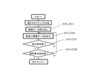
食品を出し入れすべく扉10が開かれると(ステップ1のY)、庫内照明灯34−1,34−2を点灯し(ステップ2)、扉10が閉じられると(ステップ3のY)、庫内照明灯34−1,34−2の照度を落とし(ステップ4)、しばらく、例えば数秒経過後にカメラ35−1,35−2を起動させて、庫内の食品を撮像する(ステップ5)。その後、撮像した画像データを冷蔵庫51の記憶部60に時間情報とともに記憶させ(ステップ6)、庫内照明灯34−1,34−2を消灯する(ステップ7)。なお、撮像日時を示す時間情報は、冷蔵庫自体あるいはサーバから通信を介して取得する。
When the
ここで、上記撮像時に庫内照明灯34−1,34−2の照度を落として撮像すると、食品を鮮明に撮像することができ、好適である。すなわち、庫内照明灯34−1,34−2を点灯して食品を撮像すると、収納室内面が白色系であることもあってその反射光が収納室開口部分を除く全周面から食品に強く反射し(照度が低下することなく高い照度のまま食品にはね返る)、食品が白っぽくなって、鮮明な撮像が困難となる。しかしながら、上記した例のように庫内照明灯34−1,34−2の照度を落とすと、収納室内面からの反射光の影響を大幅に低減することができて鮮明な画像の即撮像が可能となるのである。 Here, if the illuminance of the interior lighting lamps 34-1 and 34-2 is reduced during the imaging, food can be clearly captured, which is preferable. That is, when food is imaged by turning on the interior lighting lamps 34-1 and 34-2, the inner surface of the storage room may be white, and the reflected light is applied to the food from the entire peripheral surface except the opening part of the storage room. Reflected strongly (reflects on food with high illuminance without decreasing illuminance), and the food becomes whitish and clear imaging becomes difficult. However, when the illuminance of the interior lighting lamps 34-1 and 34-2 is reduced as in the above-described example, the influence of reflected light from the interior surface of the storage room can be greatly reduced, and a clear image can be captured immediately. It becomes possible.
2−1−2.冷蔵室冷却運転時の撮像
図19は冷蔵庫内の食品を出し入れした後、冷蔵室冷却時に貯蔵室の食品の撮像を行うようにした場合の動作を示すフローチャートである。
2-1-2. Image Pickup During Refrigerating Room Cooling Operation FIG. 19 is a flowchart showing an operation when food in the storage room is picked up when the refrigerator is cooled after taking in and out the food in the refrigerator.
食品を出し入れすべく扉10が開かれると(ステップ1のY)、庫内照明34−1、34−2を点灯し(ステップ2)、扉10が閉じられ(ステップ3のY)、冷蔵室の冷却運転状態か否か判断する(ステップ8)。もし、送風ファン18がON、かつダンパ22が開であり、冷蔵室の冷却運転中であれば前記扉閉時と同様、庫内照明灯34−1,34−2の照度を落とし(ステップ4)、カメラ35−1,35−2を起動させて、庫内の食品を撮像する(ステップ5)。その後、撮像した画像データを時間情報とともに冷蔵庫51の記憶部60に記憶させ(ステップ6)、庫内照明灯34−1,34−2を消灯する(ステップ7)。
When the
このように、冷蔵室冷却運転中に撮像するようにすることによって、例えば新しく収納室内に入れた食品の表面に収納室内外の温度差で結露が生じても、この結露は冷却動作によって解消され、なくなる。よって、カメラ35−1,35−2による撮像は食品包装容器に記載されている文字が読み取れるほど鮮明に行われ、好適である。 In this way, by taking an image during the cooling room cooling operation, for example, even if condensation occurs on the surface of food newly put in the storage room due to a temperature difference between the storage room and the outside, this condensation is eliminated by the cooling operation. It ’s gone. Therefore, the imaging by the cameras 35-1 and 35-2 is preferably performed so clearly that the characters written on the food packaging container can be read.
なお、前記動作の中で、扉10が閉じられると(ステップ1のY)、一度庫内照明灯34−1,34−2を消灯し、撮像前に再度庫内照明灯34−1,34−2点灯して、その照度を低下させるようにすれば、庫内照明灯34−1,34−2が点灯し続けることによる無駄な電力の消費を抑制することができる。
During the above operation, when the
2−1−3.扉開時の撮像
図20は1枚扉の場合であって、扉10を所定角度開いた時点で収納室内の食品の撮像を行うようにした場合の動作を示すフローチャートである。
2-1-3. Imaging When Door is Opened FIG. 20 is a flowchart showing an operation when a single door is used, and food in the storage room is imaged when the
食品を出し入れすべく扉10が開かれると(ステップ1のY)、庫内照明灯34−1,34−2を点灯し(ステップ2)、上記扉の開き角度が所定角度、例えば図13に示した30度の開き角度になると(ステップ10のY)、庫内照明灯34−1,34−2の照度を落とし(ステップ4)、カメラ35−1,35−2を起動させて、庫内の食品を撮像する(ステップ5)。その後、撮像した画像データを時間情報とともに冷蔵庫51の記憶部
60に記憶させ(ステップ6)、扉が閉じると(ステップ11のY)、庫内照明灯34−1,34−2を消灯する(ステップ7)。
When the
この例のように扉10を所定角度開いた時点で撮像するようにすると、すでに述べているように収納室内を広範囲に撮像でき、しかもその画像は違和感のない自然なものとなって、好適である。
If the
なお、所定角度開時に撮像する場合、扉開動作時と扉閉動作時の少なくとも2回以上撮像を行うことになる。このとき、1回の扉開から閉までの動作時間の中で、最後に撮像した画像データ(扉閉動作時)を記憶部60に記憶させることにより、食品の出し入れを終えた最新の収納室の食品状態を撮像することができる。 Note that when imaging is performed when the predetermined angle is opened, imaging is performed at least twice during the door opening operation and the door closing operation. At this time, the latest storage room in which food has been taken in and out is stored in the storage unit 60 by storing the last imaged image data (during the door closing operation) in the operation time from one door opening to closing. The state of food can be imaged.
なお、いうまでもないことではあるが、扉10の開き角度が所定角度に達するか否かを検出するステップ10において、扉10が所定角度に達する前に閉じられると庫内照明灯34−1,34−2を消灯し、再び扉10が開かれるのを待つことになる。
Needless to say, in
また、収納室内の食品の撮像とは別に、扉10の開き角度が所定角度(例えば、90度)に達した時点で撮像することによって、扉開閉、または食品収納を行なったユーザー情報を特定することが可能となる。
In addition to imaging food in the storage room, user information is specified when the
また、扉開時にユーザーの手動で撮像できる手動撮影モードを搭載してもよい。これによって、例えば、賞味期限や食材産地などのユーザーが特別に管理したい特定食材情報を簡単に管理することが可能となる。 Moreover, you may mount the manual imaging | photography mode which can image manually by a user when a door opens. Thus, for example, it is possible to easily manage specific food information that the user wants to specially manage, such as the expiration date or the food production area.
以上、撮像動作について代表的なものを例示して説明したが、前記撮像動作以外に例えば、定刻若しくは前回の撮像後所定時間が経過すると撮像する、或いは、表示端末15から撮像指示があると撮像する、等の撮像動作も考えられる。
In the above, a representative example of the imaging operation has been described. For example, in addition to the imaging operation, imaging is performed when a predetermined time elapses after a predetermined time or the previous imaging, or when an imaging instruction is given from the
2−1−4.撮像時の照明
撮像時の食品照明は、前記図18、図19、図20ですでに説明したように、庫内照明灯34−1,34−2を点灯させた上でその照度を低下させて照射し撮像する。場合によっては、収納室両側面の庫内照明灯34−1或いは収納室上面の庫内照明灯34−2のみの点灯として照度を低下させて照射し撮像することも考えられる。この照度を低下させて撮像する理由は既に述べたとおりである。
2-1-4. Illumination at the time of imaging Food illumination at the time of imaging reduces the illuminance after lighting the interior lighting lamps 34-1 and 34-2, as already described with reference to FIGS. Illuminate and image. Depending on the case, it is also conceivable to illuminate and image by lowering the illuminance as lighting only the interior lighting 34-1 on both sides of the storage room or the interior lighting 34-2 on the upper surface of the storage room. The reason for imaging with the illuminance lowered is as already described.
また、撮像時の食品照射の他の例として次のようにすることも考えられる。すなわち、図21はカメラ35−1,35−2による撮像時の庫内照明灯34−1,34−2の点・消灯の状態を示すフローチャートで、前記した図18、図19、図20の破線部分の動作に相当するものである。 As another example of food irradiation at the time of imaging, the following may be considered. That is, FIG. 21 is a flowchart showing the on / off state of the interior lighting lamps 34-1 and 34-2 at the time of imaging by the cameras 35-1 and 35-2. This corresponds to the operation of the broken line portion.
前記した図18、図19、図20での撮像は、庫内照明灯34−1,34−2を点灯させた上でその照度を低下させて撮像する例であるが、この例では収納室両側面の庫内照明灯34−1の片方づつを消灯、換言すると収納室両側面の庫内照明灯34−1の片方のみが点灯している状態にして食品を照射し撮像するようにしてある。この場合、収納室上面の庫内照明灯34−2は点灯、消灯いずれであっても良いが、庫内の照度が撮像に最適になるようにいずれかを適宜選択すればよい。 The imaging in FIGS. 18, 19, and 20 is an example in which the interior illumination lights 34-1 and 34-2 are turned on and the illuminance is lowered, and in this example, the storage room is stored. Turn off one of the interior lamps 34-1 on both sides, in other words, turn on only one of the interior lamps 34-1 on both sides of the storage room to illuminate and image food. is there. In this case, the interior illumination lamp 34-2 on the upper surface of the storage room may be either turned on or off, but any one may be appropriately selected so that the illuminance in the interior is optimal for imaging.
図21において、カメラ35−1,35−2により撮像を始める前に、すでに点灯している収納室両側面の庫内照明灯34−1のいずれか一方、例えば右庫内照明灯を消灯し(ステップ12)、左庫内照明灯により照射されている状態の食品を撮像(ステップ13)
して記憶する(ステップ14)。その後、右庫内照明灯を点灯し(ステップ15)、次に、左庫内照明灯を消灯(ステップ16)して右庫内照明灯で照射している状態の食品を撮像する(ステップ17)。その画像データを記憶し(ステップ18)、右庫内照明灯を消灯する(ステップ19)。このように食品を片方側から照射して記憶した画像データは合成して一つの画像とし、時間情報とともに記憶する。
In FIG. 21, before imaging with the cameras 35-1 and 35-2, one of the interior lighting lamps 34-1 on both sides of the storage room that has already been lit, for example, the right interior lighting lamp is turned off. (Step 12), imaging food in a state of being illuminated by the left interior lamp (Step 13)
(Step 14). Thereafter, the right interior lighting is turned on (step 15), and then the left interior lighting is turned off (step 16), and the food being irradiated with the right interior lighting is imaged (step 17). ). The image data is stored (step 18), and the right interior illumination lamp is turned off (step 19). The image data stored by irradiating food from one side in this way is combined into one image and stored together with time information.
以上のように庫内照明灯34−1,34−2を片方づつ点灯して食品を撮像し一つに合成する理由は以下の通りである。すなわち、すでに述べたとおり撮像時には庫内照明灯34−1,34−2の照度を低下させて撮像するのであるが、その照度低下はあまり大きくすると写りが暗くなって鮮明さに欠けるようになるため照度低下にも限度がある。そのためある程度の照度を維持しているが、その照度であっても、収納室内容積が小さい場合等には反射光による影響が残る場合がある。しかしながら、この例で説明したように庫内照明灯34−1の左右の片方づつを点灯して食品を撮像すると、反射光の影響を低減できて、庫内照明灯照明灯34−1が点灯している側の面は適度な明るさで撮像できる。よって、この適度の明るさで撮像した食品の左右の画像を結合する合成処理を行えば、全体が鮮明な画像となり、好適なのである。 As described above, the interior lighting lamps 34-1 and 34-2 are turned on one by one to image foods and combine them into one as follows. In other words, as described above, the illuminance of the interior lighting lamps 34-1 and 34-2 is reduced during imaging, but if the illuminance reduction is too large, the image becomes dark and lacks in clarity. Therefore, there is a limit to the decrease in illuminance. For this reason, a certain level of illuminance is maintained. However, even when the illuminance is high, there are cases in which the influence of reflected light remains when the volume of the storage room is small. However, as described in this example, when the left and right sides of the interior illumination lamp 34-1 are turned on to image food, the influence of reflected light can be reduced and the interior illumination lamp illumination 34-1 is illuminated. The surface on the side of the image can be imaged with moderate brightness. Therefore, it is preferable to perform a combining process that combines the left and right images of food captured with moderate brightness, so that the whole image becomes clear.
2−2.画像の保存と合成
次に前記した各動作によって撮像した画像データの保存と合成について説明する。
2-2. Next, storage and composition of image data captured by the above-described operations will be described.
2−2−1.サーバで保存と合成
図22はサーバ装置57で画像データを保存と合成する場合を示し、前記図21を含む図18〜図20に示す動作によって庫内が撮像されると、冷蔵庫51は無線アダプタ53からゲートウェイ装置54、ルーター装置55を介してインターネット56に接続し(ステップ20)、各カメラで撮像し記憶した個別の画像データをインターネット56に接続されたサーバ装置57に送信する(ステップ21)。インターネット56を経由して送信された画像データはサーバ装置57のサーバ制御部66によって個別の画像データを結合する合成処理(ステップ22)を行う。合成処理された画像データはサーバ装置57のデータ記憶部67にサーバから取得した現在の時間情報を撮像時刻として付加し、保存される(ステップ23)。
2-2-1. Storage and Compositing by Server FIG. 22 shows a case where image data is stored and composited by the server device 57. When the interior is imaged by the operations shown in FIG. 18 to FIG. 53 is connected to the Internet 56 via the gateway device 54 and the router device 55 (step 20), and the individual image data captured and stored by each camera is transmitted to the server device 57 connected to the Internet 56 (step 21). . The image data transmitted via the Internet 56 is subjected to a combining process (step 22) for combining individual image data by the server control unit 66 of the server device 57. The combined image data is stored by adding the current time information acquired from the server to the data storage unit 67 of the server device 57 as the imaging time (step 23).
この例のようにサーバ装置57で画像を合成し、かつ、記憶保存しておけば、冷蔵庫側の制御演算部59や記憶部60の負荷を低減することができ、インターネット対応型の冷蔵庫を安価に提供することができる。 If the image is synthesized and stored in the server device 57 as in this example, the load on the control calculation unit 59 and the storage unit 60 on the refrigerator side can be reduced, and an internet-compatible refrigerator is inexpensive. Can be provided.
2−2−2.冷蔵庫側で保存と合成
図23は冷蔵庫側で画像データを保存と合成する場合を示し、前記図21を含む図18〜図20に示す動作によって庫内が撮像されると、冷蔵庫51の制御演算部59は記憶部60に記憶した各カメラからの個別の画像データを取り出して結合し合成する(ステップ24)。合成した画像データを記憶し(ステップ25)、冷蔵庫51は無線アダプタ53からゲートウェイ装置54、ルーター装置55を介してインターネット56に接続し(ステップ20)、記憶した画像データをインターネット56に接続されたサーバ装置57に送信する(ステップ21)。インターネット56を経由して送信された合成画像データはサーバ装置57のデータ記憶部67に、サーバから取得した現在の時間情報を撮像時刻として付加し、保存される(ステップ23)。
2-2-2. Storage and Compositing on the Refrigerator Side FIG. 23 shows a case where image data is stored and combined on the refrigerator side. When the interior is imaged by the operations shown in FIGS. The unit 59 takes out individual image data from each camera stored in the storage unit 60, combines them, and combines them (step 24). The synthesized image data is stored (step 25), the refrigerator 51 is connected to the internet 56 from the
この例では冷蔵庫側の制御演算部59や記憶部60の負荷は大きくなるが、サーバ装置57のデータ記憶部67を介することなく表示端末15と画像データを送受信することができ、システム運営費を安価にすることができる。
In this example, although the load on the control calculation unit 59 and the storage unit 60 on the refrigerator side increases, image data can be transmitted and received with the
2−2−3.表示端末側で保存と合成
図24は表示端末15側で画像データを保存と合成する場合を示し、前記図21を含む図18〜図20に示す動作によって庫内が撮像されると、冷蔵庫51は無線アダプタ53からゲートウェイ装置54、ルーター装置55を介してインターネット56に接続し(ステップ20)、サーバではなく表示端末15に画像データを送信する(ステップ26)。インターネット56を経由して送信された画像データは表示端末15によって画像データを結合する合成処理(ステップ27)を行う。合成処理された画像データは表示端末15のデータ記憶部に表示端末自身が持つ時刻情報とともに保存される(ステップ28)。
2-2-3. Storage and Compositing on Display Terminal Side FIG. 24 shows a case where image data is stored and combined on the
この例の場合も表示端末15の負荷は増大するものの、冷蔵庫側の制御演算部59や記憶部60の負荷を低減することができ、インターネット対応型の冷蔵庫を安価に提供することができる。
Also in this example, although the load on the
以上、画像データの送信と合成動作について代表的なものを例示して説明したが、前記保存と合成箇所は必ずしも同一箇所、例えばサーバ装置57で行わなければならないというものではなく、例えば、冷蔵庫51で画像データを合成し、サーバ装置57で画像データを保存する、等、システムに応じて任意に設定すればよいものである。 The image data transmission and the composition operation have been described above by exemplifying typical ones. However, the storage and the composition portion are not necessarily performed at the same location, for example, the server device 57. For example, the refrigerator 51 The image data may be combined with each other and the server device 57 may store the image data.
2−3.画像データの通常の送受信
2−3−1.サーバ、冷蔵庫に保存の画像データの送受信
図25はサーバ装置57或いは冷蔵庫51と表示端末15との送受信を示すフローチャートで、サーバ装置57或いは冷蔵庫51に記憶している画像データの送受信を示すものである。
2-3. Normal transmission / reception of image data 2-3-1. Transmission / Reception of Image Data Stored in Server and Refrigerator FIG. 25 is a flowchart showing transmission / reception between server device 57 or refrigerator 51 and
まず、使用者は例えば買い物先などで表示端末15のディスプレイに表示されるサーバ接続ボタン(図示せず)を押し、サーバ装置57のデータ記憶部67に記憶された画像データの読み込み要求を行う(ステップ31)。サーバ装置57から画像データを取り込まれたかを検出し(ステップ32)、画像データが転送されてこなければ表示端末15からインターネット56に接続を行う(ステップ33)。サーバ装置57のデータ記憶部67或いは冷蔵庫の記憶部60に記憶された画像データを取り出し(ステップ34)、画像データをインターネット56を経由し、データ呼び出し元であるスマートフォン等の表示端末15に画像データを転送する(ステップ35)。サーバ装置57から画像データを取り込まれたかを検出し(ステップ32)、画像データが取り込まれたら表示端末15のディスプレイに画像データを出力する(ステップ36)
その後、表示端末15のディスプレイに表示されている拡大ボタン(図示せず)が押されたかを検知し(ステップ37)、拡大ボタンが押されたことを検知すると、ディスプレイに出力された収納室内の画像データをデジタル変換で1.1倍以上に拡大した画像データを作成する。拡大変換した画像データを表示端末15のディスプレイに出力する(ステップ36)。
First, the user presses a server connection button (not shown) displayed on the
Thereafter, it is detected whether an enlarge button (not shown) displayed on the display of the
更にその後、ディスプレイに表示されている局所表示用のテンキーボタン(図示せず)が押されたかを検知し(ステップ38)、テンキーボタンが押されたことを検知するとディスプレイに出力された収納室内の拡大画像データをテンキーボタンで指定された箇所の画像データとし、ディスプレイに出力する(ステップ36)。さらにテンキーボタンが押されたかを検知する(ステップ38)。検知されなかったら終了する。 After that, it is detected whether a local display numeric keypad (not shown) displayed on the display has been pressed (step 38), and when it is detected that the numeric keypad has been pressed, the contents of the storage room output on the display are detected. The enlarged image data is converted into image data at a location designated by the numeric keypad and output to the display (step 36). Further, it is detected whether the numeric keypad is pressed (step 38). Exit if not detected.
なお、前記拡大ボタン及び所定箇所の画像データを表示させるテンキーボタンは、ディスプレイの表面を指でスライドする方式とすればよく、このような構成とすることによって使い勝手が向上する。 It should be noted that the enlargement button and the numeric keypad for displaying image data at a predetermined location may be of a type in which the surface of the display is slid with a finger. Such a configuration improves usability.
以上のように、この冷蔵庫システムによれば、買い物先で冷蔵庫51の中身を一目で確認することができ、買い忘れが予防できるとともに、余分な食材を購入してしまう無駄をなくすることができる。また、共働きで働く家庭では、帰る間際に冷蔵庫51の収納室5内を確認し帰宅途中で食材等を購入することができ使用者にとって時間の短縮ができる。
As described above, according to this refrigerator system, the contents of the refrigerator 51 can be confirmed at a glance at a shopping destination, so that forgetting to buy can be prevented and the waste of purchasing extra ingredients can be eliminated. . In addition, in a family working together, it is possible to check the inside of the
また、拡大表示や所定箇所表示をさせることによって、表示端末15のように小型化が進んだ表示端末15でも拡大して画像を表示させることで小型の表示端末15では確認しにくい食材も確実に見ることができる。
In addition, by displaying an enlarged display or a predetermined location, it is possible to reliably display foods that are difficult to confirm on the
2−3−2.表示端末に保存の画像データの送受信
図26はすでに表示端末15に画像データを記憶保存している場合を示す。この場合は図24で述べた様に表示端末15に画像データが送信されて保存されており、この画像データの読み込み要求を行う(ステップ31)と、表示端末15の記憶部から画像データを取り込んで表示端末15のディスプレイに画像データを出力する(ステップ36)。その後の拡大表示操作や局所表示は図25で説明した通りである。
2-3-2. Transmission / Reception of Image Data Saved on Display Terminal FIG. 26 shows a case where image data is already stored and saved on the
2−3−3.画像データの切換受信
カメラ35−1,35−2で撮像した画像は、各カメラ35−1,35−2個々の撮像画像(収納室内の上半分或いは下半分)と、これらの各撮像画像を結合して合成した合成画像(収納室内を上から下まで1枚に合成した画像)が記憶保存されており、これらの画像を切換えて送受信し表示端末15に表示することができる例を示す。
2-3-3. Image data switching reception The images captured by the cameras 35-1 and 35-2 are the images captured by the respective cameras 35-1 and 35-2 (the upper half or the lower half of the storage room) and the respective captured images. An example is shown in which composite images combined and combined (images combined from the top to the bottom of the storage room into one image) are stored and stored, and these images can be switched and transmitted and displayed on the
図27はこのような場合の動作を示すフローチャートである。 FIG. 27 is a flowchart showing the operation in such a case.
まず、使用者は表示端末15のディスプレイに表示される個別画像/合成画像呼び込みボタン(図示せず)を押し(ステップ41)、個別画像或いは合成画像のいずれかの画像の呼び出しを行う(ステップ42)。以降は図25或いは図26に示すフローによって個別画像或いは合成画像のいずれかの画像データを取り込み、表示端末15のディスプレイに表示させる。
First, the user presses an individual image / composite image call button (not shown) displayed on the display of the display terminal 15 (step 41), and calls either an individual image or a composite image (step 42). ). Thereafter, either the individual image data or the composite image is captured by the flow shown in FIG. 25 or 26 and displayed on the display of the
この例のように表示端末15に表示させる画像を個別画像或いは合成画像のいずれかに切り換えることができるようにすると、通常は合成画像を呼び込んで表示させることにより収納室内の食品状況を一目で確認し、収納室隅部にある等によって食品が判別しにくいときなどは個別画像に切り換えて表示させれば確実に判別することができ、使い勝手が向上する。
When the image displayed on the
2−4.画像データ等の事前送信要求時の送受信
図28は表示端末15から画像の事前送信要求があった場合のフローチャートを示す。
2-4. Transmission / Reception at the Time of Prior Transmission Request for Image Data, etc. FIG. 28 shows a flowchart when there is a request for image prior transmission from the
まず、使用者が表示端末15を操作し、事前要求信号の要求操作を行う(ステップ51)。サーバ装置57又は冷蔵庫51はこの要求信号を受信し(ステップ52)、データ記憶部67或いは記憶部60に記憶された画像データ(個別画像データ或いは合成画像データ、以下同じ)を読み込み送信する(ステップ53)。表示端末15はサーバ装置57或いは冷蔵庫51からの画像データが取り込まれたかを検出し(ステップ54)、画像データが送信されてこなければ表示端末15からインターネット56に接続を行う(ステップ55)。サーバ装置57類は冷蔵庫51に記憶された画像データを取り出し(ステップ56)、画像データをインターネット56を経由し、表示端末15に画像データを送信する(ステップ57)。サーバ装置57から画像データを取り込まれたかを検出し(ステップ54)、画像データが検出されたら画像データの呼び出しがあるまで待機する(ステップ58のN)。画像データの呼び出しがあれば(ステップ58のY)、表示端末15のディ
スプレイに画像データを出力する(ステップ59)。
First, the user operates the
これにより、表示端末15で画像データの要求したとき、サーバ装置57へのアクセスが集中していてサーバ装置57からの画像データの送信が遅くなる場合でも、画像データの要求と同時にリアルタイムに画像データをディスプレイに表示させて画像を確認することができる。したがって、買い物先で画像データが表示されるのを待つような事態を避けることができ、買い物時間を短縮することができる。
Thus, when image data is requested on the
また、表示端末15から画像の事前送信要求があれば、サーバ装置57は冷蔵庫51の扉10が閉じられるたびに送信される画像データを都度、表示端末15に送信する設定とし、かつ、表示端末15を持っている使用者は画像データが送信されるとこれを報知するように設定しておけば、扉開閉が行われる都度これを知ることができる。よって、使用者は、例えば扉開閉回数が多くなって電力消費量が多くなりそうな場合には自宅に電話して子供等に冷蔵庫51の使用を控えるように話をすることができ、省エネに対する利便性も向上する。
Further, if there is an image pre-transmission request from the
2−5.画像データ等の送受信経路の切換
図29は表示端末15の通信系路選択時のディスプレイ表示を示す。画像データの送受信の流れはすでに述べたとおりであるが、通信の経路を変更して画像データの取得を迅速化するものである。
2-5. Switching of transmission / reception path of image data etc. FIG. 29 shows a display on the
具体的には使用者が表示端末15を、ルーター装置55を介してゲートウェイ装置54と直接行うか、またはインターネット56を介してサーバ装置57と行うかを選択可能としたものである。
Specifically, the user can select whether to perform the
図29において、70、71は表示端末15のディスプレイに表示される通信経路の選択ボタンで、70は表示端末15をルーター装置55、ゲートウェイ装置54を介して冷蔵庫51に直接接続する「ダイレクト」選択ボタン、71は更にインターネット56を介してサーバ装置57或いは冷蔵庫51に接続する「サーバ」選択ボタンである。72、73は呼び出すデータのデータ選択ボタンで、72が食品の画像データ、73が扉開閉回数等の省エネ関連データのボタンである。74は送信ボタンである。
29,
「ダイレクト」選択ボタン70はこれを選択すると、表示端末15は「ダイレクト」通信が設定される。「ダイレクト」通信が設定されている状態で、使用者が送信ボタン74に触れると、表示端末15の画像データ要求信号が、表示端末15からルーター装置55を介し直接ゲートウェイ装置(中継装置)54に送信される。ゲートウェイ装置54は、受信したデータ要求信号を、冷蔵庫51の無線アダプタ53に送信する。無線アダプタ53は、上記画像データ要求信号を受信すると、冷蔵庫51の制御演算部59にこれを送信する。冷蔵庫51の制御演算部59は画像データ要求信号を受信すると、記憶部60に保存している画像データを読み込み、無線アダプタ53、ルーター装置55を介して表示端末15に画像データを送信する。
When the “direct”
したがって、使用者が図15の破線で示すように、住居A内に位置する場合、広義には表示端末15がルーター装置55と直接通信できる位置に存在する場合、表示端末15は、ルーター装置55を介してゲートウェイ装置54と通信し、冷蔵庫51の記憶部60から画像データを直接取得することができる。
Accordingly, when the user is located in the residence A as shown by the broken line in FIG. 15, in a broad sense, when the
これによって、インターネット56へのアクセス集中による回線の混雑等により、表示端末15への使用者の操作に対する画像データの送信レスポンスに遅延が発生するような場合には、使用者が表示端末15を「ダイレクト」通信に切り替えることによって、イン
ターネット56の回線の混雑等を受けずに画像データの取得を行うことができる。よって、使用者は待ち時間なしにリアルタイムに表示端末15のディスプレイに画像を表示させて収納室5内の食品状況を確認することができる。
As a result, when a delay occurs in the transmission response of the image data in response to the user's operation to the
一方、使用者が図15の実線に示すように、住居A外に位置する場合、広義には表示端末15がルーター装置55と直接通信できない位置に存在する場合、使用者が「サーバ」選択ボタン71に触れることによって表示端末15は、インターネット56を介してサーバ装置57と通信を行い、冷蔵庫51の画像データを読み込む。すなわち、使用者は、住居A外にいる場合、「サーバ」選択ボタン71に触れて「サーバ」通信を設定すれば、遠隔地に居ても表示端末15によって冷蔵庫の画像データを取得し、食品の収納状況を知ることができる。
On the other hand, as shown by the solid line in FIG. 15, when the user is located outside the residence A, in a broad sense, when the
このように、この実施の形態における冷蔵庫システムは、使用者が、「ダイレクト」通信または「サーバ」通信のいずれか一方を選択することができ、住居A内に居るような場合には「ダイレクト」通信を選択して、インターネット回線の混雑に影響されることなく快適な状態で画像を見ることができる。 As described above, the refrigerator system in this embodiment allows the user to select either “direct” communication or “server” communication. You can select the communication and view the image in a comfortable state without being affected by the congestion of the Internet line.
2−6.表示端末での画像データの再生
2−6−1.通常の庫内画像の再生
図30は通常の庫内画像表示のフローチャートを示す。使用者は表示端末15から表示したい庫内画像の表示期間または日時を任意に設定し画像データ選択ボタン72を押す。例えば表示端末15から事前送信要求を行い、指定期間内の庫内画像取得を行う。画像データの取得の流れは図25で示した通りである。前記庫内画像は表示端末15に保存され(ステップ60)、表示端末15は、保存された画像の中から指定期間内の画像データの有無を確認し(ステップ61)、その画像データを時系列に読み込み表示端末15の表示部に出力する(ステップ62)。使用者が再生ボタンを押すと、表示端末15の表示部に時系列に読み込みこまれた画像データを自動的に切り替えて(ステップ64)表示を行う事で連続再生を行う。画像切り替えのタイミングは、表示時間が一定時間経過後、もしくは、使用者による画像送り操作があった場合に、画像切り替えを行う(ステップ63)。使用者による画像送り操作は、送りボタンの押下や、シークバーを利用し、画像を時間幅でスキップしながら閲覧する事ができる。これによって、日時指定による庫内画像検索、また時系列庫内画像の連続的な閲覧を可能にし、画像検索に要する時間を大幅に短縮する事ができ、しかも、シークバーを利用することでこれによって効果的に目的の画像を見つけ出すことが可能となる。
2-6. Reproduction of image data on display terminal 2-6-1. Reproduction of normal internal image FIG. 30 shows a flowchart of normal internal image display. The user arbitrarily sets the display period or date / time of the internal image to be displayed from the
2−6−2.庫内画像メモの作成
図31は、庫内画像を用いてメモ作成を行う場合のフローチャートを示す。使用者は表示端末15に出力された(ステップ72)庫内画像上をなぞる事で庫内画像上にメモ情報を入力し(ステップ73)、これを反映させる(ステップ74)事ができる。さらに、庫内画像領域を指でなぞり範囲を選択する事で(ステップ75)、トリミングを行い(ステップ76)部分的に画像を送信する。これによって送信画像サイズが小さくなり送信時間を短縮する事ができる為、使い勝手をよくしメモの作成と庫内画像共有が手間なく行える。
2-6-2. Creation of in-store image memo FIG. 31 shows a flowchart in the case of creating a memo using an in-store image. The user can input the memo information on the internal image by tracing the internal image output to the display terminal 15 (step 72) (step 73), and can reflect this (step 74). Further, by selecting a tracing range with the finger in the internal image area (step 75), trimming is performed (step 76) and the image is partially transmitted. As a result, the transmission image size can be reduced and the transmission time can be shortened, so that it is easy to use and the creation of memos and the sharing of images in the cabinet can be performed without any trouble.
2−6−3.庫内変化検出再生
図32は、庫内画像の変化検出を行うとともに、庫内画像の連続再生を行う場合のフローチャートを示す。表示端末15に保存されその表示部に画像データが出力され(ステップ66)、使用者は表示されている庫内画像を指でなぞり食材または庫内の領域を指定し(ステップ67)自動再生を行うことにより、前回表示していた画像と現在表示している画像との特定領域を比較し(ステップ68)、変化を検出すると自動再生を停止する。こ
れによって、使用者は画像データを一枚ずつ確認することなく、自動再生を行う事で庫内の特定領域、または食材の有無の変化を容易に知ることができ、在庫管理を容易に行うことができる。さらに、特定の領域を指定することにより画像変化の検出処理量も減少し一定の処理速度を保つことも可能となる。なお、前記前回表示画像と現在表示画像との特定領域を比較してその変化有無を検出するのは冷蔵庫の制御演算部59あるいはサーバ装置57のサーバ制御部66で行わせるのがよい。
2-6-3. Storage Change Detection Reproduction FIG. 32 shows a flowchart in the case of detecting the change of the image in the warehouse and continuously reproducing the image in the warehouse. The image data is stored in the
2−6−4.追記情報の再生
庫内画像情報に加えて、2−1−3項に記した、扉開閉または食品収納したユーザー情報や、ユーザーが手動で撮像した特定食材情報などの追記情報を同時に表示してもよい。
2-6-4. Reproduction of postscript information In addition to in-chamber image information, additional information such as user information on door opening / closing or food storage, or specific food information manually imaged by the user, as described in section 2-1-3, is displayed simultaneously. Also good.
なお、ユーザー情報、または特定食材情報は、庫内画像上に一部のみ表示し、端末上でタップ操作等を行うことで、すべての情報を表示できるようにしている。 Note that only a part of the user information or specific food information is displayed on the in-store image, and all information can be displayed by performing a tap operation or the like on the terminal.
なお、表示するユーザー情報は、画像情報や、予め登録した顔情報から顔認識を行った結果のテキスト情報(名前など)などがある。 The user information to be displayed includes image information, text information (name, etc.) as a result of performing face recognition from face information registered in advance.
<3.管理>
3−1.食品の保存管理
次に本発明の要旨である食品の保存管理について説明する。
<3. Management>
3-1. Food Storage Management Next, food storage management, which is the gist of the present invention, will be described.
これは上記した庫内変化検出再生の考え方を利用して行っているもので、図33は図16に示す冷蔵庫の制御演算部59と記憶部60とで構成されている食品保存管理制御部のブロック図、図34は同食品保存管理制御を示すフローチャートを示す。 This is performed using the above-described concept of in-chamber change detection and regeneration. FIG. 33 shows a food storage management control unit composed of the refrigerator control calculation unit 59 and the storage unit 60 shown in FIG. FIG. 34 is a block diagram showing the food storage management control.
図33において、77は保存対象食品を特定する対象物特定手段で、この実施の形態では表示端末15の表示画面に映し出された対象食品をタッチまたはエリア選択すれば特定できるようにすることによって構成してある。そしてこの対象物特定手段77は画像操作で特定した対象物の特異点を抽出して対象物を特定するようにしてある。78は冷蔵庫の記憶部60内に構成されている画像記憶部で、カメラで撮像された画像のうち前記対象物特定手段77で特定された対象食品の画像を記憶している。79は同じく冷蔵庫の記憶部60内に構成されている保存期間記憶部で、前記対象物特定手段77で特定された対象食品が最初に撮像、すなわち収納室に投入された時点からの経過時間、すなわち保存期間を記憶している。80は比較手段で、カメラで撮像した画像のうちの対象食品画像と、前回撮像されて画像記憶部に記憶されている対象食品画像とを比較する。81は前記比較手段80の比較の結果対象食品画像に変化があれば保存期間記憶部79に記憶されている保存期間を変更する補正演算手段である。
In FIG. 33,
次に上記構成からなる食品保存管理の動作を図34のフローチャートを用いて説明する。
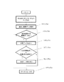
図18から図21に示す動作によって収納室内が画像が撮像され記憶されたのち、対象物特定手段77によって対象食品が特定されると(ステップ81)、画像記憶部78がその対象食品画像を記憶するとともに保存期間記憶部79がその投入時点からの経過時間を記憶(ステップ82)していく。
Next, the food storage management operation configured as described above will be described with reference to the flowchart of FIG.
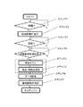
After the storage room is imaged and stored by the operation shown in FIGS. 18 to 21, when the target food is specified by the object specifying means 77 (step 81), the
その後、扉の開閉が行われる(ステップ83)、すなわち、食品の出し入れがあると、図18から図21に示す動作によって収納室内が撮像され(ステップ84)、比較手段80がこの新たに撮像された画像のうちの対象食品新画像を前回扉開閉時に記憶されている対象食品の旧画像と比較する(ステップ85)。 Thereafter, the door is opened and closed (step 83), that is, when food is taken in and out, the storage room is imaged by the operation shown in FIGS. 18 to 21 (step 84), and the comparison means 80 is newly imaged. The new image of the target food is compared with the old image of the target food stored when the door was opened / closed last time (step 85).
この新旧画像の比較の結果、画像に大きな変化があれば補正演算手段81は対象食品が同一食品であっても買い換えられて新規に入れ替わった、または消費されてなくなったものと判断して保存期間記憶部79に記憶している保存期間をリセットし変更(ステップ86)して、新規に入れ替わった場合には新たにその時点からの経過時間を記憶していく。その後、例えば、インターネットを介して表示端末15に送信して保存期間が変更したことを報知する(ステップ87)。また、画像に変化がなければ対象物画像を保持、保存期間を継続する。
If there is a large change in the image as a result of the comparison between the old and new images, the correction calculation means 81 determines that the target food is the same food and has been replaced and newly replaced or no longer consumed. The retention period stored in the
図35は対象食品の新旧画像変化検出の一例を示すフローチャートで、新旧画像に変化有を検出すると(ステップ85)、当該対象物が存在するかを確認し(ステップ88)、存在しなければ、対象物は消費されてなくなったと判断して対象物画像や保存期間をキャンセルして(ステップ91)、対象物がなくなったことを表示端末15に送信し、報知する(ステップ87)。対象物が存在すれば、新旧画像変化は食品の大きさが減少方向、例えば食事に供するなどして大きさが減少しているか否かを確認し(ステップ88)、減少していれば、対象物を特定継続使用中として対象物画像を保持、保存期間を継続し、減少していなければ対象食品が同一食品であっても買い換えられて新規に入れ替わったものと判断して保存期間をリセットし変更(ステップ86)して、新たにその時点からの経過時間を記憶していく。
FIG. 35 is a flowchart showing an example of detection of a new and old image change of a target food. When a change is detected in a new and old image (step 85), it is confirmed whether the target object exists (step 88). It is determined that the object is no longer consumed, cancels the object image and the storage period (step 91), and transmits to the
図36は対象食品の新旧画像変化検出のさらに他の例を示すフローチャートで、新旧画像比較で変化なし(ステップ85)であった場合、対象物画像を保持、保存期間を継続する。新旧画像に変化有を検出すると、さらに当該対象食品の新旧画像比較までの食品不在時間が予め定めた所定時間以上か否かを確認(ステップ92)し、所定時間以上経過していれば対象食品が同一食品であっても入れ替えられたものと判断して保存期間をリセットし変更(ステップ86)して、新規に入れ替わった場合には新たにその時点からの経過時間を記憶していく。これは対象食品が不在、すなわち収納室内に収納されていない時間が長いと、料理や食事で持ち出されるとは考えにくく、使用者が買い出しに行って同一食品を新たに入れ替えたものと考えられ、このような場合は保存期間を再設定するである。 FIG. 36 is a flowchart showing still another example of detection of new and old image changes of the target food. When there is no change in the new and old image comparison (step 85), the target image is held and the storage period is continued. When it is detected that there is a change in the old and new images, it is further checked whether or not the food absence time until the new and old image comparison of the target food is longer than a predetermined time (step 92). Even if they are the same food, it is determined that they have been replaced, and the retention period is reset and changed (step 86), and when it is newly replaced, the elapsed time from that point is newly stored. This is because the target food is absent, that is, if it is not stored in the storage room for a long time, it is unlikely that it will be taken out by cooking or eating, and it is considered that the user went shopping and newly replaced the same food, In such a case, the retention period is reset.
ここで、前記対象物特定手段77は、使用者によって操作されて対象物を特定した後は、カメラで撮像された画像の中から対象物特有の特異点を抽出して特定し続けるので、食品の収納位置が出し入れのたびに変わっても対象物を正確に特定することができ、精度の高い保存管理が可能となる。
Here, since the
3−2.特異点の抽出
次に、対象食品の特異点の抽出について説明する。
3-2. Extraction of Singularity Next, extraction of singularity of the target food will be described.
前項に記載の通り、対象物特定手段77は、使用者の画像操作で特定した食品の中心部付近の画像データから色相成分データを抽出し、これをこの食品の特異点データとして保存する。次に、対象物特定手段77は新旧画像変化検出から、新旧画像の変化領域の位置と大きさを表した変化エリアデータを取得する。対象物特定手段77は、この変化エリアデータを基に特定する対象食品を限定し、変化エリアデータの中心部付近の色相成分データを抽出する。この色相成分データと先に保存された各食品の特異点データとを比較し、一定以上の一致があったものを特定の食品として認識する。
As described in the previous section, the
認識したい対象食品の色相成分データの抽出領域はできる限り、事前に保存された特異点データと同じような位置の色相成分データを抽出できることが望ましい。そのため、色相成分データを抽出する領域の大きさは一定とせず、変化エリアデータの大きさに比例して、色相抽出領域の大きさを変化させることで食品の置かれる位置により、変化領域の大きさが変化したとしても、ほぼ同じ位置の色相成分データが抽出可能となる。 It is desirable to extract the hue component data at the same position as the singular point data stored in advance as much as possible in the extraction region of the hue component data of the target food to be recognized. For this reason, the size of the area for extracting the hue component data is not constant, and the size of the change area depends on the position of the food by changing the size of the hue extraction area in proportion to the size of the change area data. Even if the brightness changes, it is possible to extract the hue component data at substantially the same position.
なお、各食品の特異点データは一つである必要はなく、例えば、向きや角度によって色相が異なる食品については、複数個の特異点データを保存してもよい。 In addition, the singular point data of each food does not need to be one. For example, a plurality of singular point data may be stored for foods having different hues depending on directions and angles.
また、庫内照明灯34−1、34−2の近くでは、照明の特性による色成分が食品の色相成分データに影響を与え、本来の食品の色相成分データと異なるデータになることがある。これにより、保存している特異点の色相成分データと一致せず、食品の特定ができなくなる可能性がある。これを回避するために、あらかじめ、照明の色相成分データを保存しておき、食品の変化エリアデータが示す変化領域が照明に近い場合は、照明の色相成分を保存していた特異点の色相成分に加え、色相成分データを補正してマッチング判定することで、誤検出を避けることができる。 Also, in the vicinity of the interior lighting lamps 34-1 and 34-2, the color component due to the lighting characteristics may affect the hue component data of the food, and may be different from the original hue component data of the food. Accordingly, there is a possibility that the food component cannot be specified because it does not match the hue component data of the stored singular point. In order to avoid this, the hue component data of the lighting is stored in advance, and if the change area indicated by the food change area data is close to the lighting, the hue component of the singular point that stored the lighting hue component In addition, erroneous detection can be avoided by correcting the hue component data and determining matching.
また、棚板30−1〜30−4は前記棚板の少なくとも80%以上の位置で透明度が70%以下になるように構成されている。これによって、対象物特定手段77は新旧画像変化検出から変化エリアデータを取得する際に、各棚板30−1〜30−4の裏側にある食材を誤検出することを抑制することができるので、変化エリアデータの検出精度を高めることができる。
Further, the shelf boards 30-1 to 30-4 are configured such that the transparency is 70% or less at a position of at least 80% or more of the shelf board. Thereby, when the
なお、本実施の形態では、対象食品の特異点は色相成分データを基に抽出したが、これに限らず、食品の輪郭などを抽出することで、対象食品を判別する手段を用いることも可能である。 In this embodiment, the singular point of the target food is extracted based on the hue component data. However, the present invention is not limited to this, and a means for determining the target food can be used by extracting the outline of the food. It is.
なお、本発明の実施の形態で例示した冷蔵庫及び冷蔵庫システムは次のような利点も併せ持っているので、記載しておく。 In addition, since the refrigerator and refrigerator system which were illustrated in embodiment of this invention have the following advantages, it describes.
すなわち、この実施の形態の冷蔵庫では、カメラ35−1,35−2は収納室5の前面側から収納室5内の食品を撮像するが、このとき庫内照明灯13−0,34−2も収納室5の前面側に設けてあって、収納室5内の食品をカメラ35−1,35−2による撮像方向と同じ前面側から照射している。したがって、その撮像画像は庫内照明灯34−1,34−2が収納室5の奥壁に設けてある場合のような暗さや見にくさはなく、鮮明な画像となる。また、撮像した画像を明るくし、鮮明にする画像処理をサーバ装置57に求める必要もなくなる。
That is, in the refrigerator of this embodiment, the cameras 35-1 and 35-2 image food in the
また、上記カメラ35−1,35−2と庫内照明灯34−1,34−2とは前記棚板30−1〜30−4の前端より前方側に位置するように設けてあるから、カメラ35−1,35−2で撮像した収納室5内の画像は、使用者が冷蔵庫51の扉10を開いて実際に見る状態と同じとなる。したがって、使用者が表示端末15に画像データを表示させてみたときに何ら違和感を持つことなく収納室5内の食品状況を確認することができる。しかも、庫内照明灯34−1,34−2は棚板30−1〜30−4の前端前方から棚板上の食品を照らすので、棚板30−1〜30−4の前端部に載置されている食品も明るく、かつ、鮮明に撮像することができる。
Moreover, since the said cameras 35-1, 35-2 and the interior lighting lamps 34-1, 34-2 are provided so that it may be located ahead from the front end of the said shelf boards 30-1 to 30-4, Images in the
また、上記カメラ35−1,35−2は冷蔵庫51の扉10内面部に設けるとともに、庫内照明灯34−1,34−2は収納室5の開口縁両側壁部に設けてあるから、カメラ35−1,35−2はまず収納室5の左右略中央部に位置することになる。したがって、当該カメラ35−1,35−2で撮像した画像を使用者が冷蔵庫51の扉10を開いて実際に見る状態により近い形とすることができる。加えて、上記カメラ35−1,35−2と棚板上の食品との間の距離を大きくとって収納室5内の広い範囲を撮像することができ、より広範囲の食品の収納状況を表示端末15で確認することが可能となる。
The cameras 35-1 and 35-2 are provided on the inner surface of the
また、カメラ35−1,35−2は扉内面の扉ポケット33−1,33−2の前後方向の略中央部分に位置するように設けてあるから、収納室5内の食品のみならず扉ポケット33−1,33−2に収納している食品、例えば牛乳パック等をもその一部を撮像することができる。使用者は自分で収納したものであるから、その一部が写っているだけでもそれが何であるかを認識することができる。よって、収納室内のほぼ全ての食品を撮像することが可能となる。
Further, since the cameras 35-1 and 35-2 are provided so as to be positioned at a substantially central portion in the front-rear direction of the door pockets 33-1 and 33-2 on the inner surface of the door, not only the food in the
また、カメラは図9(a)に示すように収納容器専用のカメラ14−3を設ければ収納容器31内の食品も鮮明に撮像することができる。更に図9(b)で示すようにカメラ35−2を上下動可能にしたり、図9(c)のように上下回動自在とすることによって収納容器31内の食品も二つのカメラ、すなわち、少ないカメラ数で効率よく撮像することができる。
Further, as shown in FIG. 9A, if the camera is provided with a dedicated camera 14-3, the food in the
一方、前記庫内照明灯34−1,34−2は、図7、図10から明らかなようにカメラ35−1,35−2より奥側の位置に設け、庫内照明灯34−1,34−2の光が直接カメラ35−1,35−2の撮像部に入り込まないように設けてあるから、庫内照明灯34−1,34−2の光がカメラ35−1,35−2に入ってカメラ35−1,35−2の写りが悪くなることを防止でき、常に良好な画像を得ることができる。これは、庫内照明灯35−1,35−2のカメラ側に遮光部を設けたり、或いは庫内照明灯34−1,34−2を構成するLED等の光源を斜め後方向きに傾斜配置するなどの構成を採用しても同様の効果が得られる。 On the other hand, the interior lighting lamps 34-1 and 34-2 are provided at positions farther from the cameras 35-1 and 35-2, as is apparent from FIGS. Since the light of 34-2 is provided so as not to directly enter the imaging units of the cameras 35-1 and 35-2, the lights of the interior lighting lamps 34-1 and 34-2 are emitted from the cameras 35-1 and 35-2. The camera 35-1 and 35-2 can be prevented from being deteriorated, and a good image can always be obtained. This is because a light shielding part is provided on the camera side of the interior lighting lamps 35-1 and 35-2, or light sources such as LEDs constituting the interior lighting lamps 34-1 and 34-2 are inclined obliquely rearwardly. The same effect can be obtained by adopting a configuration such as.
また、上記庫内照明灯34−1,34−2は収納室内の照度が150ルックス〜200ルックスであり、このままの照度で撮像すると、図18の撮像動作の項で説明したように食品が白っぽく写り、判別がしにくいものとなる。そのため、この実施形態では照度を低下させて撮像する構成としてある。これによりCCDカメラやCMOSカメラであっても鮮明な撮像を可能とする。この庫内照明灯34−1,34−2の照度は、扉10を閉じて、或いは扉10を開いて撮像するときだけ通常時よりも低い照度となるよう制御演算部59によって制御するようにしても良く、このような制御をすることによって撮像しない通常時はこれまで通りの照度を保って庫内を見やすくしつつ鮮明な撮像を可能とすることができる。上記照度の低下は、例えば庫内照明灯34−1,34−2のいずれか一方或いはその両方の庫内照明灯34−1,34−2の一部を消灯させたり、両方の庫内照明灯34−1,34−2の照度を低下させる等種々考えられ、適宜選択すればよい。
In addition, the interior lighting lamps 34-1 and 34-2 have an illuminance in the storage room of 150 to 200 lux, and when the image is taken with the illuminance as it is, the food is whitish as described in the section of the imaging operation in FIG. It is difficult to see and distinguish. Therefore, in this embodiment, it is set as the structure which reduces illuminance and images. This enables clear imaging even with a CCD camera or a CMOS camera. The illuminances of the interior lighting lamps 34-1 and 34-2 are controlled by the control calculation unit 59 so that the illuminance is lower than normal only when the
また、上記カメラ35−1,35−2で撮像した収納室5内の画像は、それぞれのカメラ35−1,35−2の画像をサーバ装置57に送信してサーバ装置57、或いは冷蔵庫51、或いは表示端末15内で結合処理し合成するが、この実施の形態では上記画像の合成処理が容易になる。
The images in the
すなわち、上記カメラ35−1,35−2は、棚板30−1〜30−4の前端と対応する扉内面部、この例では上段の棚板30−1と3段目の棚板30−3の前端と対応する扉内面部に設けてあるから、それぞれのカメラ35−1,35−2の撮像は図34中の線Zが境界線となるように棚板30−1,30−3を中心として撮像することになる。
That is, the cameras 35-1 and 35-2 are door inner surfaces corresponding to the front ends of the shelf boards 30-1 to 30-4, in this example, the upper shelf board 30-1 and the
したがって、二つのカメラ35−1,35−2で撮像した収納室5内の画像データは、境界線Zとなる2段目の棚板30−2部分で結合処理することを可能とする。すなわち、図37の「撮像生画像」に示すように上下それぞれの画像には棚板30−2が共通して写っており、この「撮像生画像」の湾曲を修正して「湾曲修正処理後画像」にした後、前記上下の画像に移っている共通の棚板30−2を合致させれば収納室全体の撮像画像となる。その結果、画像の結合処理時に棚板の上に置かれている各食品を、各食品ごとに位置合
わせして結合するきわめて困難な補正処理をする必要がなくなって、画像の結合処理は容易となる。よって、画像結合のための処理プログラムも簡素なものとすることができ、画像結合処理のためのサーバ装置57、或いは冷蔵庫51、或いは表示端末15の制御部分の容量も大容量のものを必要としなくなり、処理速度のスピーディ化に貢献できる。
Therefore, the image data in the
さらに、二つのカメラ35−1,35−2は、高さ調整ができない棚板30−1、棚板30−3の略前方位置に設けてあることから、高さ調節可能な棚板30−2の高さが変更された場合でも、画像の結合処理時に、棚板30−2の高さに応じて結合処理する範囲を調整することで、容易に画像の結合処理が可能となる。 Further, since the two cameras 35-1 and 35-2 are provided substantially in front of the shelf plate 30-1 and the shelf plate 30-3 that cannot be adjusted in height, the shelf plate 30-that can be adjusted in height. Even when the height of 2 is changed, the image combining process can be easily performed by adjusting the range to be combined according to the height of the shelf 30-2 during the image combining process.
以上、具体的な構成を例示して本発明の冷蔵庫と冷蔵庫システムを説明したが、本発明は上記構成に限定されるものではない。すなわち、今回開示した実施の形態はすべての点で例示であって制限的なものではないと考えられるべきである。つまり、本発明の範囲は上記した説明ではなくて特許請求の範囲によって示され、特許請求の範囲と均等の意味及び範囲内でのすべての変更が含まれることが意図される。 As mentioned above, although the specific structure was illustrated and the refrigerator and refrigerator system of this invention were demonstrated, this invention is not limited to the said structure. In other words, the embodiment disclosed this time should be considered as illustrative in all points and not restrictive. That is, the scope of the present invention is shown not by the above description but by the scope of claims, and is intended to include all modifications within the meaning and scope equivalent to the scope of claims.
例えば、食品の保存管理として本実施の形態ではインターネットを利用して収納状態を確認できるようにした冷蔵庫及び冷蔵システムに適用して、対象食品の保存期間が所定時間以上になると携帯式の表示端末15に報知するようにしたが、これは冷蔵庫自体に設けられている運転状態等を表示して報知する報知手段に報知してもよいし、インターネット等を利用しない単体の冷蔵庫に適用してもよいものである。なお、携帯式の表示端末に15に報知する様にすれば使用者がどのような場所に居ても確実に報知を知ることができる利点がある。
For example, in the present embodiment, as a food storage management, it is applied to a refrigerator and a refrigeration system in which the storage state can be confirmed using the Internet, and when the storage period of the target food exceeds a predetermined time, a
また、画像記憶部78、保存期間記憶部79、比較手段80、補正演算手段81等を冷蔵庫側の制御演算部59と記憶部60で構成し場合を例示したが、これはサーバ装置57側で構成してもよいものであるし、冷蔵庫とサーバ装置57とで分担してもよいものである。
Moreover, although the case where the
さらに、対象物特定手段77は表示端末15の表示画面に映し出された対象食品をタッチすれば特定できるようにしたものを例示したが、これは例えば食品名を音声などで直接入力するような方式で構成してもよく、そして携帯式の表示端末にとどまらず冷蔵庫自体に設けられている報知手段に構成してもよいものであり、冷蔵庫単体の場合にはその報知手段に構成してもよいものである。
Further, the
また、通信形態も、前記実施の形態では表示端末15と冷蔵庫51の無線アダプタ53、インターネット56との通信経路にゲートウェイ装置54を介在させるものを例示したが、このゲートウェイ装置54は必ずしも必要でなく、ルーター装置55を介して直接に表示端末15及び冷蔵庫51の無線アダプタ53、インターネット56と通信するように構成してもよく、このようにすることによってシステム構成の簡素化が図れる。
In the above embodiment, the gateway device 54 is exemplified in the communication path between the
また前記実施の形態では使用者が住居A外に居るときにはサーバ装置57から画像データを取得するようにしたが、サーバ装置57を介さずに、表示端末15からインターネット56およびルーター装置55、ゲートウェイ装置54と通信し、冷蔵庫51の記憶部60に記憶されている画像データを冷蔵庫51から直接取り込むように構成してもよい。この場合及び「ダイレクト」通信を行う場合は、冷蔵庫51の記憶部60で画像の結合処理を行い、この結合処理後の画像データを送信するのが好ましい。
In the above embodiment, the image data is acquired from the server device 57 when the user is outside the residence A. However, the Internet 56, the router device 55, and the gateway device are connected from the
更にこの実施の形態では、表示端末15のディスプレイに「ダイレクト」選択ボタン70と「サーバ」選択ボタン71を表示させて、使用者が「ダイレクト」通信と「サーバ」
通信の選択を行う場合を例示したが、これは表示端末15にルーター装置55の電波をキャッチすると自動的に「ダイレクト」通信に切り替わる機能を持たせて「ダイレクト」通信が自動的に選択されるようにしても良く、使い勝手を向上させることができる。
Further, in this embodiment, a “direct”
Although the case of selecting communication is illustrated, this is because the
本発明は、食品収納時に何ら手間をかけることなく確実な保存管理ができる使い勝手の良い冷蔵庫を提供することができるから、家庭用の冷蔵庫をはじめとして各種の冷蔵庫に適用可能である。 INDUSTRIAL APPLICABILITY Since the present invention can provide an easy-to-use refrigerator that can be reliably stored and managed without taking any trouble at the time of food storage, it can be applied to various refrigerators including home refrigerators.
1 冷蔵庫本体
2 外箱
3 内箱
4 断熱材
5 冷蔵室(収納室)
6 切替室
7 製氷室
8 冷凍室
9 野菜室
10 扉
11〜14 引き出し式扉(扉)
15 表示端末(画像表示手段)
15a ディスプレイ
16 冷却室
17 冷却器
18 送風ファン
19 コンプレッサ
20 放熱パイプ
21 キャピラリーチューブ
22 ダンパ
23 収納枠体
24 端末保持体
25 タッチパネル
26 隙間
27 枠体
28 凹部
29、29a スモークシート
30−1〜30−4 棚板
31 収納容器
32−1〜32−4 側壁凸部
33−1〜33−8 扉ポケット
34−1,34−2 庫内照明灯
35−1,35−2,35−3 カメラ(撮像手段)
36 センターピラー
41 カメラモジュール
50 冷蔵庫システム
51 冷蔵庫
53 無線アダプタ(通信装置)
53a 「接続」ボタン
54 ゲートウェイ装置(中継装置)
55 ルーター装置
56 インターネット
57 サーバ装置
58 インターフェイス(I/F)
59 制御演算部
60 記憶部
61 扉開閉検出部
62 ファン駆動回路
63 コンプレッサ駆動回路
64 交流電源
65 サーバ用インターフェイス
66 サーバ制御部
67 データ記憶部
70 「ダイレクト」選択ボタン
71 「サーバ」選択ボタン
72 画像データ選択ボタン
73 省エネ関連データ選択ボタン
74 送信ボタン
77 対象物特定手段
78 画像記憶部
79 保存期間記憶部
80 比較手段
81 補正演算手段
A 住居
DESCRIPTION OF
6
15 Display terminal (image display means)
DESCRIPTION OF
36 Center pillar 41
53a "Connect" button 54 Gateway device (relay device)
55 Router device 56 Internet 57 Server device 58 Interface (I / F)
59 Control Calculation Unit 60 Storage Unit 61 Door Open / Close Detection Unit 62 Fan Drive Circuit 63 Compressor Drive Circuit 64 AC Power Supply 65 Server Interface 66 Server Control Unit 67
Claims (5)
前記冷蔵庫本体を仕切ることで構成される収納室と、
前記収納室を覆う断熱扉と、
前記収納室もしくは前記断熱扉に設けられ前記収納室の内部を撮像する撮像手段と、
前記撮像手段により撮像された画像から対象物を特定する対象物特定手段と、
前記対象物特定手段により特定された対象物の保存期間を記憶する保存期間記憶部と、
前記対象物特定手段により特定された対象物の画像を所定時間の前後で比較する比較手段と、
前記保存期間記憶部に記憶される保存期間を所定の条件下で補正する補正演算手段と、を備え、
前記補正演算手段は、前記比較手段の比較結果に基づいて前記保存期間記憶部に記憶されている保存期間を変更補正することを特徴とする冷蔵庫。 A refrigerator body which is composed of an inner box and an outer box and has an open front,
A storage room configured by partitioning the refrigerator body;
A heat insulating door covering the storage room;
Imaging means provided in the storage chamber or the heat insulating door for imaging the inside of the storage chamber;
Object identifying means for identifying an object from an image captured by the imaging means;
A storage period storage unit for storing a storage period of the object specified by the object specifying means;
Comparison means for comparing images of the object specified by the object specifying means before and after a predetermined time;
Correction calculation means for correcting the storage period stored in the storage period storage unit under a predetermined condition,
The said correction calculating means changes and correct | amends the preservation | save period memorize | stored in the said preservation | save period memory | storage part based on the comparison result of the said comparison means, The refrigerator characterized by the above-mentioned.
Priority Applications (1)
| Application Number | Priority Date | Filing Date | Title |
|---|---|---|---|
| JP2014006551A JP6303127B2 (en) | 2013-03-29 | 2014-01-17 | refrigerator |
Applications Claiming Priority (5)
| Application Number | Priority Date | Filing Date | Title |
|---|---|---|---|
| JP2013071719 | 2013-03-29 | ||
| JP2013071719 | 2013-03-29 | ||
| JP2013181871 | 2013-09-03 | ||
| JP2013181871 | 2013-09-03 | ||
| JP2014006551A JP6303127B2 (en) | 2013-03-29 | 2014-01-17 | refrigerator |
Publications (2)
| Publication Number | Publication Date |
|---|---|
| JP2015072109A true JP2015072109A (en) | 2015-04-16 |
| JP6303127B2 JP6303127B2 (en) | 2018-04-04 |
Family
ID=53014597
Family Applications (1)
| Application Number | Title | Priority Date | Filing Date |
|---|---|---|---|
| JP2014006551A Active JP6303127B2 (en) | 2013-03-29 | 2014-01-17 | refrigerator |
Country Status (1)
| Country | Link |
|---|---|
| JP (1) | JP6303127B2 (en) |
Cited By (10)
| Publication number | Priority date | Publication date | Assignee | Title |
|---|---|---|---|---|
| EP3128274A1 (en) * | 2015-08-05 | 2017-02-08 | Whirlpool Corporation | Object recognition system for an appliance and method for managing household inventory of consumables |
| JP2017106671A (en) * | 2015-12-10 | 2017-06-15 | 三菱電機株式会社 | Refrigerator, image management system in refrigerator and program |
| JP2018013272A (en) * | 2016-07-20 | 2018-01-25 | 三菱電機株式会社 | refrigerator |
| WO2018016054A1 (en) * | 2016-07-21 | 2018-01-25 | 三菱電機株式会社 | Refrigerator system |
| JP2018155430A (en) * | 2017-03-16 | 2018-10-04 | 日本電気株式会社 | Refrigerator inside monitoring system, refrigerator inside monitoring method, program, and refrigerator |
| KR20190075088A (en) * | 2016-11-23 | 2019-06-28 | 칭다오 하이얼 조인트 스탁 씨오.,엘티디. | How to measure whether or not the temperature of the refrigerator has been exceeded. |
| JP2019109026A (en) * | 2017-12-20 | 2019-07-04 | パナソニックIpマネジメント株式会社 | refrigerator |
| JP2020003207A (en) * | 2019-10-01 | 2020-01-09 | 東芝ライフスタイル株式会社 | Food control method, food control system and refrigerator |
| JP2021081184A (en) * | 2021-02-25 | 2021-05-27 | 東芝ライフスタイル株式会社 | Food management method, food management system and refrigerator |
| US11156970B2 (en) | 2015-08-05 | 2021-10-26 | Whirlpool Corporation | Foodstuff sensing appliance |
Citations (11)
| Publication number | Priority date | Publication date | Assignee | Title |
|---|---|---|---|---|
| JPH0545041A (en) * | 1991-08-09 | 1993-02-23 | Sharp Corp | Device for controlling storage space in freezer-refrigerator |
| JPH109753A (en) * | 1996-06-26 | 1998-01-16 | Matsushita Refrig Co Ltd | Food inventory control device for refrigerator-freezer |
| JP2001099561A (en) * | 1999-09-28 | 2001-04-13 | Sharp Corp | Refrigerator |
| JP2001165554A (en) * | 1999-12-09 | 2001-06-22 | Nippon Telegraph & Telephone East Corp | Refrigerator |
| JP2002092308A (en) * | 2000-09-14 | 2002-03-29 | Sanyo Electric Co Ltd | Information processing method, information processing device, and server |
| JP2005037086A (en) * | 2003-07-17 | 2005-02-10 | Sanyo Electric Co Ltd | Refrigerator and food managing method for refrigerator |
| US20060237427A1 (en) * | 2005-04-07 | 2006-10-26 | Logan James D | Smart cabinets |
| JP2010121784A (en) * | 2008-11-17 | 2010-06-03 | Toshiba Corp | Stock management device of refrigerator |
| US20120023971A1 (en) * | 2010-07-29 | 2012-02-02 | Min Deulre | Refrigerator and method for controlling the same |
| JP2012193873A (en) * | 2011-03-15 | 2012-10-11 | Nikon Corp | Storage device |
| JP2013113526A (en) * | 2011-11-30 | 2013-06-10 | Toshiba Corp | Refrigerator |
-
2014
- 2014-01-17 JP JP2014006551A patent/JP6303127B2/en active Active
Patent Citations (11)
| Publication number | Priority date | Publication date | Assignee | Title |
|---|---|---|---|---|
| JPH0545041A (en) * | 1991-08-09 | 1993-02-23 | Sharp Corp | Device for controlling storage space in freezer-refrigerator |
| JPH109753A (en) * | 1996-06-26 | 1998-01-16 | Matsushita Refrig Co Ltd | Food inventory control device for refrigerator-freezer |
| JP2001099561A (en) * | 1999-09-28 | 2001-04-13 | Sharp Corp | Refrigerator |
| JP2001165554A (en) * | 1999-12-09 | 2001-06-22 | Nippon Telegraph & Telephone East Corp | Refrigerator |
| JP2002092308A (en) * | 2000-09-14 | 2002-03-29 | Sanyo Electric Co Ltd | Information processing method, information processing device, and server |
| JP2005037086A (en) * | 2003-07-17 | 2005-02-10 | Sanyo Electric Co Ltd | Refrigerator and food managing method for refrigerator |
| US20060237427A1 (en) * | 2005-04-07 | 2006-10-26 | Logan James D | Smart cabinets |
| JP2010121784A (en) * | 2008-11-17 | 2010-06-03 | Toshiba Corp | Stock management device of refrigerator |
| US20120023971A1 (en) * | 2010-07-29 | 2012-02-02 | Min Deulre | Refrigerator and method for controlling the same |
| JP2012193873A (en) * | 2011-03-15 | 2012-10-11 | Nikon Corp | Storage device |
| JP2013113526A (en) * | 2011-11-30 | 2013-06-10 | Toshiba Corp | Refrigerator |
Cited By (19)
| Publication number | Priority date | Publication date | Assignee | Title |
|---|---|---|---|---|
| US11156970B2 (en) | 2015-08-05 | 2021-10-26 | Whirlpool Corporation | Foodstuff sensing appliance |
| US11556889B2 (en) | 2015-08-05 | 2023-01-17 | Whirlpool Corporation | Object recognition system for an appliance and method for managing household inventory of consumables |
| EP3128274A1 (en) * | 2015-08-05 | 2017-02-08 | Whirlpool Corporation | Object recognition system for an appliance and method for managing household inventory of consumables |
| EP3904803A1 (en) * | 2015-08-05 | 2021-11-03 | Whirlpool Corporation | Object recognition system for an appliance and method for managing household inventory of consumables |
| US10474987B2 (en) | 2015-08-05 | 2019-11-12 | Whirlpool Corporation | Object recognition system for an appliance and method for managing household inventory of consumables |
| JP2017106671A (en) * | 2015-12-10 | 2017-06-15 | 三菱電機株式会社 | Refrigerator, image management system in refrigerator and program |
| JP2018013272A (en) * | 2016-07-20 | 2018-01-25 | 三菱電機株式会社 | refrigerator |
| WO2018016054A1 (en) * | 2016-07-21 | 2018-01-25 | 三菱電機株式会社 | Refrigerator system |
| KR20180100636A (en) | 2016-07-21 | 2018-09-11 | 미쓰비시덴키 가부시키가이샤 | Refrigerator system |
| JPWO2018016054A1 (en) * | 2016-07-21 | 2018-11-08 | 三菱電機株式会社 | Refrigerator system |
| DE112016007082T5 (en) | 2016-07-21 | 2019-04-04 | Mitsubishi Electric Corporation | REFRIGERATOR SYSTEM |
| KR20190075088A (en) * | 2016-11-23 | 2019-06-28 | 칭다오 하이얼 조인트 스탁 씨오.,엘티디. | How to measure whether or not the temperature of the refrigerator has been exceeded. |
| KR102180257B1 (en) | 2016-11-23 | 2020-11-19 | 칭다오 하이얼 조인트 스탁 씨오.,엘티디. | How to measure whether an item that is over temperature is placed in the refrigerator |
| JP2018155430A (en) * | 2017-03-16 | 2018-10-04 | 日本電気株式会社 | Refrigerator inside monitoring system, refrigerator inside monitoring method, program, and refrigerator |
| JP2019109026A (en) * | 2017-12-20 | 2019-07-04 | パナソニックIpマネジメント株式会社 | refrigerator |
| JP7113281B2 (en) | 2017-12-20 | 2022-08-05 | パナソニックIpマネジメント株式会社 | refrigerator |
| JP2020003207A (en) * | 2019-10-01 | 2020-01-09 | 東芝ライフスタイル株式会社 | Food control method, food control system and refrigerator |
| JP2021081184A (en) * | 2021-02-25 | 2021-05-27 | 東芝ライフスタイル株式会社 | Food management method, food management system and refrigerator |
| JP7084517B2 (en) | 2021-02-25 | 2022-06-14 | 東芝ライフスタイル株式会社 | Food management method, food management system, refrigerator |
Also Published As
| Publication number | Publication date |
|---|---|
| JP6303127B2 (en) | 2018-04-04 |
Similar Documents
| Publication | Publication Date | Title |
|---|---|---|
| JP6303125B2 (en) | Refrigerator and refrigerator system | |
| JP6303127B2 (en) | refrigerator | |
| JP6229142B2 (en) | Refrigerator and refrigerator system | |
| JP6221048B2 (en) | refrigerator | |
| JP6322803B2 (en) | Refrigerator and refrigerator system | |
| JP6167330B2 (en) | Refrigerator and refrigerator system | |
| JP6167331B2 (en) | Refrigerator and refrigerator system | |
| JP6167289B2 (en) | Refrigerator and refrigerator system thereof | |
| JP6167327B2 (en) | refrigerator | |
| JP6361014B2 (en) | Refrigerator and refrigerator system | |
| JP6485678B2 (en) | Refrigerator and refrigerator system | |
| JP2018004247A (en) | Refrigerator | |
| JP6212700B2 (en) | Refrigerator and refrigerator system thereof | |
| JP6167288B2 (en) | refrigerator | |
| JP2019007728A (en) | refrigerator | |
| JP2017142059A (en) | refrigerator | |
| JP6167329B2 (en) | refrigerator | |
| JP6671002B2 (en) | refrigerator | |
| JP6114916B2 (en) | refrigerator | |
| JP6145701B2 (en) | refrigerator | |
| JP6167328B2 (en) | refrigerator | |
| JP2017106715A (en) | refrigerator | |
| JP6145702B2 (en) | refrigerator |
Legal Events
| Date | Code | Title | Description |
|---|---|---|---|
| RD01 | Notification of change of attorney |
Free format text: JAPANESE INTERMEDIATE CODE: A7421 Effective date: 20160519 |
|
| A621 | Written request for application examination |
Free format text: JAPANESE INTERMEDIATE CODE: A621 Effective date: 20160822 |
|
| A977 | Report on retrieval |
Free format text: JAPANESE INTERMEDIATE CODE: A971007 Effective date: 20170524 |
|
| A131 | Notification of reasons for refusal |
Free format text: JAPANESE INTERMEDIATE CODE: A131 Effective date: 20170606 |
|
| A601 | Written request for extension of time |
Free format text: JAPANESE INTERMEDIATE CODE: A601 Effective date: 20170706 |
|
| A521 | Request for written amendment filed |
Free format text: JAPANESE INTERMEDIATE CODE: A523 Effective date: 20170822 |
|
| TRDD | Decision of grant or rejection written | ||
| A01 | Written decision to grant a patent or to grant a registration (utility model) |
Free format text: JAPANESE INTERMEDIATE CODE: A01 Effective date: 20180123 |
|
| A61 | First payment of annual fees (during grant procedure) |
Free format text: JAPANESE INTERMEDIATE CODE: A61 Effective date: 20180205 |
|
| R151 | Written notification of patent or utility model registration |
Ref document number: 6303127 Country of ref document: JP Free format text: JAPANESE INTERMEDIATE CODE: R151 |