JP2015049700A5 - - Google Patents
Download PDFInfo
- Publication number
- JP2015049700A5 JP2015049700A5 JP2013180776A JP2013180776A JP2015049700A5 JP 2015049700 A5 JP2015049700 A5 JP 2015049700A5 JP 2013180776 A JP2013180776 A JP 2013180776A JP 2013180776 A JP2013180776 A JP 2013180776A JP 2015049700 A5 JP2015049700 A5 JP 2015049700A5
- Authority
- JP
- Japan
- Prior art keywords
- coin
- guide wall
- guide
- conveyor belt
- coins
- Prior art date
- Legal status (The legal status is an assumption and is not a legal conclusion. Google has not performed a legal analysis and makes no representation as to the accuracy of the status listed.)
- Granted
Links
- 238000001514 detection method Methods 0.000 description 36
- 230000032258 transport Effects 0.000 description 36
- 238000003780 insertion Methods 0.000 description 18
- 238000000926 separation method Methods 0.000 description 17
- 239000006096 absorbing agent Substances 0.000 description 13
- 238000000151 deposition Methods 0.000 description 13
- 230000035939 shock Effects 0.000 description 13
- 239000011347 resin Substances 0.000 description 11
- 229920005989 resin Polymers 0.000 description 11
- 238000003860 storage Methods 0.000 description 9
- 230000001105 regulatory Effects 0.000 description 8
- 210000000614 Ribs Anatomy 0.000 description 7
- 239000002184 metal Substances 0.000 description 7
- 230000003014 reinforcing Effects 0.000 description 6
- 239000000463 material Substances 0.000 description 5
- 238000011144 upstream manufacturing Methods 0.000 description 5
- 230000000875 corresponding Effects 0.000 description 4
- 238000000034 method Methods 0.000 description 4
- 239000000203 mixture Substances 0.000 description 4
- 238000005192 partition Methods 0.000 description 4
- 230000002093 peripheral Effects 0.000 description 4
- 230000000717 retained Effects 0.000 description 4
- 238000005096 rolling process Methods 0.000 description 4
- 238000007599 discharging Methods 0.000 description 3
- 230000003287 optical Effects 0.000 description 3
- 230000036544 posture Effects 0.000 description 3
- 238000007796 conventional method Methods 0.000 description 2
- 239000000428 dust Substances 0.000 description 2
- 230000000694 effects Effects 0.000 description 2
- 230000005484 gravity Effects 0.000 description 2
- 239000011343 solid material Substances 0.000 description 2
- 238000003756 stirring Methods 0.000 description 2
- 238000004642 transportation engineering Methods 0.000 description 2
- 238000004804 winding Methods 0.000 description 2
- 241001270131 Agaricus moelleri Species 0.000 description 1
- 229910001335 Galvanized steel Inorganic materials 0.000 description 1
- 229920002803 Thermoplastic polyurethane Polymers 0.000 description 1
- 230000001154 acute Effects 0.000 description 1
- 230000005540 biological transmission Effects 0.000 description 1
- 238000006243 chemical reaction Methods 0.000 description 1
- 230000003247 decreasing Effects 0.000 description 1
- 238000010586 diagram Methods 0.000 description 1
- 239000008397 galvanized steel Substances 0.000 description 1
- 230000001939 inductive effect Effects 0.000 description 1
- 238000003825 pressing Methods 0.000 description 1
- 239000003638 reducing agent Substances 0.000 description 1
Images
Description
本発明は、複数金種の硬貨を個別の硬貨払出装置から1つずつ放出して一本の搬送ベルト上に落下させ、当該搬送ベルト上に所定の間隔で垂立する一対の案内壁によって硬貨受取口に搬送する硬貨出金装置における硬貨搬送案内装置に関する。
特に本発明は、一対の案内壁間に並列した硬貨が挟まれて硬貨受取口に搬送されないことを防止できる硬貨出金装置の硬貨搬送案内装置に関する。
さらに詳しくは、一対の案内壁間に並列した硬貨が挟まれて硬貨受取口に搬送されないことを防止すると共に、安価に構成できるようにした硬貨出金装置の硬貨搬送案内装置に関する。
なお、本明細書で使用する「硬貨」は、日本硬貨、米国硬貨及びユーロ硬貨他全ての硬貨を含んでいる。
According to the present invention, coins of a plurality of denominations are ejected one by one from individual coin dispensing devices, dropped onto a single conveyor belt, and coins are formed by a pair of guide walls that are vertically suspended on the conveyor belt. The present invention relates to a coin conveyance guide device in a coin dispensing device that conveys to a receiving port.
In particular, the present invention relates to a coin conveyance guide device for a coin dispensing device that can prevent coins juxtaposed in parallel between a pair of guide walls from being conveyed to a coin receiving port.
More specifically, the present invention relates to a coin conveyance guide device for a coin dispensing apparatus that prevents coins juxtaposed in parallel between a pair of guide walls from being conveyed to a coin receiving port and can be configured at low cost.
The “coin” used in this specification includes Japanese coins, US coins, euro coins and all other coins.
第1の従来技術として、保留した硬貨を1つずつ弾き出す弾出口を有する同一構造の硬貨払出装置を前記弾出方向線に対し交差する直線に沿って複数並列した第1硬貨払出装置列と第2硬貨払出装置列とを所定の間隔で前記第1硬貨払出装置列と前記第2硬貨払出装置列との弾出方向線が相対する硬貨払出装置列に向くように並列し、前記第1硬貨払出装置列と第2硬貨払出装置列の間に硬貨受取口に向かって進行する搬送ベルトを配置すると共に、当該搬送ベルトの両側に垂立する一対の案内壁を配置することによって、前記第1硬貨払出装置列又は第2硬貨払出装置列を構成する硬貨払出装置から弾き出された硬貨を前記搬送ベルト上に落下させた後、前記搬送ベルトによって前記一対の案内壁に案内させつつ前記硬貨受取口に向けて搬送するようにした硬貨出金装置が知られている(例えば特許第4665087号)。
これを図21〜図23を参照して説明すれば、一対のローラ10、12間に搬送ベルト14が張り渡され、搬送ベルト14の上面に対し垂立する一対の第1案内壁16と第2案内壁18とが搬送される最大硬貨直径よりも広い間隔で平行に配置されている。
したがって、第1案内壁16又は第2案内壁18の上側から放出された硬貨C1、C2は、搬送ベルト14上に落下し、当該搬送ベルト14の矢印方向の進行によって、第1案内壁16及び第2案内壁18に案内されつつ硬貨受取口20へ向かって搬送される。
As a first prior art, a first coin dispensing device row in which a plurality of coin dispensing devices having the same structure having bullet outlets for ejecting the retained coins one by one are arranged in parallel along a straight line intersecting the ejection direction line. Two coin dispenser rows arranged in parallel at a predetermined interval so that the ejection direction lines of the first coin dispenser row and the second coin dispenser row face the opposite coin dispenser row, and the first coin By disposing a conveying belt that moves toward the coin receiving port between the dispensing device row and the second coin dispensing device row, and by arranging a pair of guide walls that are suspended on both sides of the conveying belt, After the coins ejected from the coin dispensing device constituting the coin dispensing device row or the second coin dispensing device row are dropped onto the conveyor belt, the coin receiving port is guided to the pair of guide walls by the conveyor belt. Carry for Coin apparatus is known which is adapted to (for example, Japanese Patent No. 4665087).
21 to 23, the conveying belt 14 is stretched between the pair of rollers 10 and 12, and the first guide wall 16 and the pair of first guide walls 16 that are suspended from the upper surface of the conveying belt 14. The two guide walls 18 are arranged in parallel at intervals wider than the maximum coin diameter to be conveyed.
Accordingly, the coins C1 and C2 released from the upper side of the first guide wall 16 or the second guide wall 18 fall on the conveyor belt 14, and the first guide wall 16 and It is conveyed toward the coin receiving port 20 while being guided by the second guide wall 18.
第2の従来技術として、硬貨を迅速かつ確実に一方向へ搬送するため、搬送ベルト上に所定の間隔で平行に、かつ、当該搬送ベルト面に対し垂立配置された第1案内壁と第2案内壁との下端部を、当該搬送ベルト面に近づくほど互いに相対する第1案内壁又は第2案内壁側に近づくように傾斜させてなる硬貨搬送路における硬貨自走防止機構が知られている(特開平11-16025)。 As a second prior art, in order to quickly and surely convey coins in one direction, a first guide wall and a first guide wall arranged in parallel on a conveyor belt at a predetermined interval and vertically with respect to the conveyor belt surface. 2. A mechanism for preventing free-running coins in a coin transport path is known in which the lower end of the guide wall is inclined so as to approach the first guide wall or the second guide wall facing each other as the transport belt surface is approached. (JP-A-11-16025).
第3の従来技術として、硬貨を平ベルト上に載せて搬送する場合において、当該ベルトが硬貨を搬送する方向において、前下がりに傾斜させることで払出方向へ確実に払い出すようにした硬貨処理装置が知られている(実用新案登録第2597102号)。なお、第3の従来技術には開示されていないが、平ベルト上には当該平ベルトに対し垂立すると共に所定の間隔で平行に配置された一対の案内壁が配置されていることは当業者において周知の技術である。 As a third conventional technique, when a coin is placed on a flat belt and transported, the coin processing apparatus is configured to reliably pay out in the payout direction by inclining forward in the direction in which the belt transports the coin. Is known (utility model registration No. 2597102). Although not disclosed in the third prior art, a pair of guide walls that are suspended from the flat belt and arranged in parallel at a predetermined interval are arranged on the flat belt. This is a well-known technique in the traders.
第4の従来技術として、ベルト上で輪転している硬貨を倒して確実に搬送するため、ベルト上方に紐部材を配置することで、輪転している硬貨を当該紐部材によってベルト上に倒すようにした硬貨処理装置が知られている(特開平9-231442)。 As a fourth conventional technique, in order to defeat the coins that are rotating on the belt and reliably convey the coins, the string member is arranged above the belt so that the coins that are rotating on the belt are overlaid on the belt by the string member. A coin processing apparatus is known (Japanese Patent Laid-Open No. 9-231442).
第5の従来技術として、ベルト上で輪転している硬貨を倒して確実に搬送するため、ベルトの上方に傾斜面を有する硬貨倒し部材を配置した硬貨処理装置の硬貨倒し機構が知られている(特開2011-003047) As a fifth prior art, there is known a coin flipping mechanism of a coin processing device in which a coin flipping member having an inclined surface is arranged above the belt in order to reliably convey the coins rotating on the belt. (JP 2011-003047)
第1の従来技術においては、搬送ベルト14上に落下した硬貨C1、C2(出金が多い場合は更に多数の硬貨Cが第1案内壁16又は第2案内壁18に衝突して様々な方向に跳ね返り、また、搬送ベルト14上に落下した反動で跳ね上がる挙動によって、図23に示すように硬貨Cが第1案内壁16又は第2案内壁18にもたれかかった状態で搬送ベルト14上に立った状態になり、搬送ベルト14の進行に合わせて輪転することから、搬送ベルト14に対して一定位置に静止し、放出された硬貨が硬貨受取口へ払い出されない問題が希に発生することがある。
また、希にではあるが、図22に示すように、硬貨の組合せ、換言すれば硬貨直径の組合せにより2つの硬貨C1、C2が並列状態で第1案内壁16と第2案内壁18との間に嵌り込み、硬貨受取口20に払い出されない問題がある。この問題を詳述すれば、第1案内壁16と第2案内壁18とは巨視的に見れば平行に配置されているものの、微視的に見ればそれらは許容される範囲で波打っていることから、それらの間隔は搬送ベルト14の進行方向線MDに対して直交する方向の間隔が大きい大間隔部WD、及び、間隔が狭い小間隔部NWが存在する。このため、大間隔部WDにおいて2つの硬貨C1、C2が並列した後、下流側の小間隔部NWに進行した場合、それら硬貨C1、C2が第1案内壁16と第2案内壁18との間にくさび状に挟まって停止し、結果として硬貨受取口20へ払い出されない詰まり現象を生じる問題がある。並列する硬貨Cの少なくとも一方が、周面にギザを有する場合、この傾向は一層高まるものである。同様に、一枚の硬貨が搬送ベルト14に面接触し、他の一枚が搬送ベルト上に立った状態で第1案内壁16と第2案内壁18との間にくさび状に挟まって停止することもある。
これらの問題を解消するため、第1案内壁16と第2案内壁18との許容平面度を考慮した場合において、2つの硬貨が並列した場合にそれらが挟まれないように第1案内壁16と第2案内壁18との間隔を定めることが考えられる。しかし、硬貨直径は国毎に設定され、様々な組合せがあることから、国毎に第1案内壁16と第2案内壁18との間隔を定めねばならず、グローバルな製品の場合は俄に採用できない問題がある。仮に国毎に第1案内壁16と第2案内壁18との間隔を定める場合、間隔の調整機構が必要になり、コストアップになることからこの方策も俄に採用することはできない。
また、全ての国の硬貨が並列した場合であっても、それら硬貨が第1案内壁16と第2案内壁18との間に嵌り込まれないように、第1案内壁16と第2案内壁18との間隔を広くすることが考えられるが、装置が大型化するので採用できない。
In the first prior art, coins C1 and C2 that have fallen on the conveyor belt 14 (if there are many withdrawals, more coins C collide with the first guide wall 16 or the second guide wall 18 in various directions. The coin C is standing on the conveyor belt 14 in a state where the coin C leans against the first guide wall 16 or the second guide wall 18 as shown in FIG. Since the belt rotates in accordance with the progress of the conveyor belt 14, there may be a rare problem that the coins that are released are stopped at a certain position with respect to the conveyor belt 14 and the discharged coins are not paid out to the coin receiving port. is there.
Moreover, although rarely, as shown in FIG. 22, two coins C1 and C2 are arranged in parallel with each other by a combination of coins, in other words, a combination of coin diameters, between the first guide wall 16 and the second guide wall 18. There is a problem of being inserted in between and not being paid out to the coin receiving port 20. To elaborate on this problem, the first guide wall 16 and the second guide wall 18 are arranged in parallel when viewed macroscopically, but when viewed microscopically, they undulate within an allowable range. Therefore, there are a large interval portion WD having a large interval in a direction orthogonal to the traveling direction line MD of the conveyance belt 14 and a small interval portion NW having a small interval. For this reason, when two coins C1 and C2 are juxtaposed in the large interval portion WD and then proceed to the small interval portion NW on the downstream side, the coins C1 and C2 are in contact with the first guide wall 16 and the second guide wall 18. There is a problem that a wedge phenomenon is caused to stop, and as a result, a clogging phenomenon that the coins are not paid out to the coin receiving port 20 occurs. This tendency is further increased when at least one of the coins C arranged in parallel has a jagged surface. Similarly, one coin is brought into surface contact with the conveyor belt 14 and the other one is standing on the conveyor belt and stopped in a wedge shape between the first guide wall 16 and the second guide wall 18. Sometimes.
In order to solve these problems, when the allowable flatness of the first guide wall 16 and the second guide wall 18 is taken into consideration, the first guide wall 16 is prevented from being sandwiched when two coins are juxtaposed. It is conceivable to determine the distance between the first guide wall 18 and the second guide wall 18. However, since the coin diameter is set for each country and there are various combinations, the distance between the first guide wall 16 and the second guide wall 18 must be determined for each country. There is a problem that cannot be adopted. If the distance between the first guide wall 16 and the second guide wall 18 is determined for each country, an adjustment mechanism for the distance is required, which increases the cost, and this measure cannot be adopted as well.
Further, even when the coins of all countries in parallel, so that they coins are not incorporated fit between the first guide wall 16 and the second guide wall 18, a first guide wall 16 and the second guide Although it is conceivable to increase the distance between the wall 18 and the apparatus, the apparatus becomes larger and cannot be used.
第2の従来技術においては、案内壁の下端部が傾斜していることから、硬貨は必然的に所定角度以上傾けられるので、硬貨が案内壁にもたれかかって立った状態で輪転することは解消されるが、第1の従来技術同様に2枚の硬貨が並列した状態で一対の案内壁の間に挟まって硬貨受取口へ払い出されないという問題は解消できない。 In the second prior art, since the lower end portion of the guide wall is inclined, the coin is inevitably tilted by a predetermined angle or more, so that the coin does not rotate while leaning against the guide wall. However, as in the first prior art, the problem that the two coins are sandwiched between the pair of guide walls in a state where the coins are juxtaposed and cannot be paid out to the coin receiving port cannot be solved.
第3の従来技術においては、平ベルトが前下がりに配置されているので、平ベルトの進行と合わせて迅速に硬貨を硬貨受取口へ搬送できる利点があるが、第1の従来技術同様に2枚の硬貨が並列した状態で一対の案内壁の間に挟まって硬貨受取口へ払い出されないという問題は解消できない。 In the third prior art, since the flat belt is disposed at the front lower side, there is an advantage that the coin can be quickly conveyed to the coin receiving port in accordance with the progress of the flat belt. The problem that the coins are sandwiched between a pair of guide walls and are not paid out to the coin receiving port cannot be solved.
第4の従来技術においては、ベルト上で輪転している硬貨を紐部材に接触させて倒すので輪転による払出の遅延又は不払出を解消できるものの、硬貨の案内壁は平行に配置されているので、第1の従来技術同様に2枚の硬貨が並列した状態で一対の案内壁の間に挟まって硬貨受取口へ払い出されないという問題は解消できない。 In the fourth prior art, the coins rotating on the belt are brought into contact with the string member and knocked down so that the delay or non-payment of payout due to the roll can be eliminated, but the coin guide walls are arranged in parallel. As in the first prior art, the problem that the two coins are sandwiched between the pair of guide walls in a state where they are juxtaposed and cannot be paid out to the coin receiving port cannot be solved.
第5の従来技術においては、ベルト上で輪転している硬貨を硬貨倒し部材に接触させて倒すので輪転による払出の遅延又は不払出を解消できるものの、硬貨の案内壁は平行に配置されているので、第1の従来技術同様に2枚の硬貨が並列した状態で案内壁の間に挟まって硬貨受取口へ払い出されないという問題は解消できない。 In the fifth prior art, the coins rotating on the belt are brought into contact with the coins and brought down so that the delay or non-payment of payout due to the rolls can be eliminated, but the coin guide walls are arranged in parallel. Therefore, as in the first prior art, the problem that the two coins are sandwiched between the guide walls in a state where they are juxtaposed and cannot be paid out to the coin receiving port cannot be solved.
本発明の基本的目的である第1の目的は、搬送ベルト上に硬貨が並列した場合であっても、一対の案内壁間に挟まって払い出されないことがない硬貨出金装置の硬貨搬送案内装置を提供することである。
本発明の従的な目的である第2の目的は、搬送ベルト上に硬貨が並列した場合であっても、一対の案内壁間に挟まって払い出されないことがなく、かつ、迅速に硬貨受取口へ搬送できる硬貨出金装置の硬貨搬送案内装置を提供することである。
本発明の従的な目的である第3の目的は、搬送ベルト上に硬貨が並列した場合であっても、一対の案内壁間に挟まって払い出されないことがない硬貨出金装置の硬貨搬送案内装置を安価に提供することである。
A first object, which is a basic object of the present invention, is a coin transport guide for a coin dispensing device that is not pinched between a pair of guide walls even when coins are juxtaposed on a transport belt. Is to provide a device.
The second object of the present invention is to receive coins quickly without being pinched between a pair of guide walls even when coins are juxtaposed on a conveyor belt. It is providing the coin conveyance guide apparatus of the coin dispensing device which can be conveyed to a mouth.
A third object, which is a subordinate object of the present invention, is the coin transportation of a coin dispensing device that is not pinched between a pair of guide walls even when coins are juxtaposed on a transportation belt. It is to provide a guide device at low cost.
この目的を達成するため、本発明は以下のように構成されている。
第1の発明における硬貨出金装置の硬貨搬送案内装置は、保留した硬貨を1つずつ所定の放出方向線に沿って放出する払出開口を有する硬貨払出装置を前記放出方向線に対し交差する方向に延在する直線に沿って複数並列した硬貨払出装置列を硬貨受取口に向かって進行する搬送ベルトに沿って配置すると共に、前記搬送ベルトは前記硬貨払出装置列における払出開口の下方において垂立する第1案内壁と、前記第1案内壁に対し平行に配置され、かつ、垂立する第2案内壁とで前記搬送ベルトの上方に立体箱形の払出空間を形成し、
前記硬貨払出装置列を構成する硬貨払出装置の払出開口から放出した硬貨を前記搬送ベルト上に落下させた後、前記搬送ベルトによって前記第1案内壁と前記第2案内壁とによって案内しつつ前記硬貨受取口に向けて搬送するようにした硬貨出金装置の硬貨搬送案内装置において、
前記硬貨受取口から遠い前記第1案内壁又は前記第2案内壁の少なくとも一方の下部は、下方ほど相対する第1案内壁又は第2案内壁に向かって順次近づくように傾斜すると共に、前記硬貨受取口に近づくほど前記第1案内壁又は前記第2案内壁から遠ざかるように形成されてなる
ことを特徴とする硬貨出金装置の硬貨搬送案内装置である。
In order to achieve this object, the present invention is configured as follows.
In the coin dispensing guide device of the coin dispensing apparatus according to the first aspect of the present invention, the coin dispensing apparatus having a dispensing opening for discharging the held coins one by one along a predetermined discharge direction line intersects the discharge direction line. A plurality of coin dispenser rows arranged in parallel along a straight line extending along a straight line extending along a conveyor belt that advances toward a coin receiving port, and the conveyor belt is suspended below a dispensing opening in the coin dispenser row. A three-dimensional box-shaped payout space is formed above the conveyor belt with the first guide wall and the second guide wall arranged parallel to the first guide wall and suspended;
The coin released from the dispensing opening of the coin dispensing device constituting the coin dispensing device row is dropped onto the conveyor belt, and then guided by the first and second guide walls by the conveyor belt. In the coin transport guide device of the coin dispensing device that is transported toward the coin receiving port,
The lower part of at least one of the first guide wall or the second guide wall that is far from the coin receiving slot is inclined so as to gradually approach toward the first guide wall or the second guide wall that are opposed to each other downward, and the coin. It is a coin conveyance guide device of a coin dispensing device, characterized in that it is formed so as to move away from the first guide wall or the second guide wall as it approaches the receiving port.
第2の発明における硬貨出金装置の硬貨搬送案内装置は、保留した硬貨を1つずつ放出する払出開口を有する硬貨払出装置を放出方向線に対し交差する直線に沿って複数並列した硬貨払出装置列を硬貨受取口に向かって進行する搬送ベルトに沿って配置すると共に、前記搬送ベルトは前記硬貨払出装置列における払出開口の下方において垂立する第1案内壁と、前記第1案内壁に対し平行に配置され、かつ、垂立する第2案内壁とで前記搬送ベルトの上方に立体箱形の払出空間を形成し、
前記硬貨払出装置列を構成する硬貨払出装置の払出開口から放出した硬貨を前記搬送ベルト上に落下させた後、前記搬送ベルトによって前記第1案内壁と前記第2案内壁とによって案内しつつ前記硬貨受取口に向けて搬送するようにした硬貨出金装置の硬貨搬送案内装置において、
前記硬貨受取口から遠い少なくとも前記第1案内壁及び前記第2案内壁の両方の下部は下方ほど相対する第1案内壁又は第2案内壁に向かって順次近づくように傾斜すると共に、前記硬貨受取口に近づくほど前記第1案内壁又は前記第2案内壁から遠ざかるように形成されてなる
ことを特徴とする硬貨出金装置の硬貨搬送案内装置である。
According to a second aspect of the present invention, there is provided a coin dispensing apparatus including a plurality of coin dispensing devices each having a plurality of coin dispensing devices each having a dispensing opening that discharges retained coins one by one along a straight line that intersects a discharge direction line. A row is disposed along a conveyor belt that travels toward a coin receiving port, and the conveyor belt is suspended from a first guide wall that is suspended below a dispensing opening in the coin dispensing device row, and the first guide wall. Forming a three-dimensional box-shaped payout space above the conveyor belt with the second guide wall arranged in parallel and vertically,
The coin released from the dispensing opening of the coin dispensing device constituting the coin dispensing device row is dropped onto the conveyor belt, and then guided by the first and second guide walls by the conveyor belt. In the coin transport guide device of the coin dispensing device that is transported toward the coin receiving port,
At least lower portions of both the first guide wall and the second guide wall far from the coin receiving port are inclined so as to approach each other toward the first guide wall or the second guide wall facing each other downward, and the coin receiving A coin transport guide device for a coin dispensing device, characterized in that the coin guide device is formed so as to move away from the first guide wall or the second guide wall as it approaches the mouth.
第3の発明における硬貨出金装置の硬貨搬送案内装置は、保留した硬貨を1つずつ放出する払出開口を有する硬貨払出装置を放出方向線に対し交差する直線に沿って複数並列した硬貨払出装置列を硬貨受取口に向かって進行する搬送ベルトに沿って配置すると共に、前記搬送ベルトは前記硬貨払出装置列における払出開口の下方において垂立する第1案内壁と、前記第1案内壁に対し平行に配置され、かつ、垂立する第2案内壁とで前記搬送ベルトの上方に立体箱形の払出空間を形成し、
前記硬貨払出装置列を構成する硬貨払出装置の払出開口から放出した硬貨を前記搬送ベルト上に落下させた後、前記搬送ベルトによって前記第1案内壁と前記第2案内壁とによって案内しつつ前記硬貨受取口に向けて搬送するようにした硬貨出金装置の硬貨搬送案内装置において、
前記硬貨受取口から遠い少なくとも前記第1案内壁又は前記第2案内壁の一方の下部は下方ほど相対する第1案内壁又は第2案内壁に向かって順次近づくように傾斜してなると共に、前記硬貨受取口に近づくほど相対する前記第1案内壁又は前記第2案内壁から遠ざかるように形成され、
前記硬貨受取口から最も遠い前記硬貨払出装置に相対する前記第1案内壁及び前記第2案内壁の下端間の間隙は前記硬貨払出装置から放出される硬貨の直径を超え、
更に、前記搬送ベルトは、当該搬送ベルトが静止した状態において、前記硬貨受取口側に向かって前下がりに傾斜し、立った硬貨が自重により前記硬貨受取口側へ向かって転動を開始する傾斜を有する
ことを特徴とする硬貨出金装置の硬貨搬送案内装置である。
According to a third aspect of the present invention, there is provided a coin dispensing apparatus including a plurality of coin dispensing devices each having a plurality of coin dispensing devices each having a dispensing opening for discharging a held coin one by one along a straight line intersecting the discharge direction line. A row is disposed along a conveyor belt that travels toward a coin receiving port, and the conveyor belt is suspended from a first guide wall that is suspended below a dispensing opening in the coin dispensing device row, and the first guide wall. Forming a three-dimensional box-shaped payout space above the conveyor belt with the second guide wall arranged in parallel and vertically,
The coin released from the dispensing opening of the coin dispensing device constituting the coin dispensing device row is dropped onto the conveyor belt, and then guided by the first and second guide walls by the conveyor belt. In the coin transport guide device of the coin dispensing device that is transported toward the coin receiving port,
At least a lower portion of the first guide wall or the second guide wall far from the coin receiving port is inclined so as to gradually approach the first guide wall or the second guide wall facing each other downward, and It is formed so as to move away from the first guide wall or the second guide wall facing each other as it approaches the coin receiving port,
The gap between the lower ends of the first guide wall and the second guide wall facing the coin dispensing device farthest from the coin receiving port exceeds the diameter of the coins discharged from the coin dispensing device,
Further, the conveyor belt is inclined forward and downward toward the coin receiving port when the conveyor belt is stationary, and the inclined coin starts rolling toward the coin receiving port by its own weight. It is a coin conveyance guide apparatus of the coin dispensing device characterized by having.
第4の発明における硬貨出金装置の硬貨搬送案内装置は、保留した硬貨を1つずつ放出する払出開口を有する硬貨払出装置を放出方向線に対し交差する直線に沿って複数並列した硬貨払出装置列を硬貨受取口に向かって進行する搬送ベルトに沿って配置すると共に、前記搬送ベルトは前記硬貨払出装置列における払出開口の下方において垂立する第1案内壁と、前記第1案内壁に対し平行に配置され、かつ、垂立する第2案内壁とで前記搬送ベルトの上方に立体箱形の払出空間を形成し、
前記硬貨払出装置列を構成する硬貨払出装置の払出開口から放出した硬貨を前記搬送ベルト上に落下させた後、前記搬送ベルトによって前記第1案内壁と前記第2案内壁とによって案内しつつ前記硬貨受取口に向けて搬送するようにした硬貨出金装置の硬貨搬送案内装置において、
前記硬貨払出口から遠い少なくとも前記第1案内壁又は前記第2案内壁の一方の下部は下方ほど相対する第1案内壁又は第2案内壁に向かって順次近づくように傾斜してなると共に、前記硬貨受取口に近づくほど相対する前記第1案内壁又は前記第2案内壁から遠ざかるようにそれぞれ一枚の板状体を板金加工により形成され、
前記硬貨受取口から最も遠い前記硬貨払出装置に相対する前記第1案内壁及び前記第2案内壁の下端間の間隙は前記硬貨払出装置から放出される硬貨の直径を超える
ことを特徴とする硬貨出金装置の硬貨搬送案内装置である。
According to a fourth aspect of the present invention, there is provided a coin dispensing apparatus including a plurality of coin dispensing apparatuses each having a dispensing opening that discharges a retained coin one by one along a straight line intersecting a discharge direction line. A row is disposed along a conveyor belt that travels toward a coin receiving port, and the conveyor belt is suspended from a first guide wall that is suspended below a dispensing opening in the coin dispensing device row, and the first guide wall. Forming a three-dimensional box-shaped payout space above the conveyor belt with the second guide wall arranged in parallel and vertically,
The coin released from the dispensing opening of the coin dispensing device constituting the coin dispensing device row is dropped onto the conveyor belt, and then guided by the first and second guide walls by the conveyor belt. In the coin transport guide device of the coin dispensing device that is transported toward the coin receiving port,
At least the lower part of the first guide wall or the second guide wall far from the coin payout outlet is inclined so as to gradually approach toward the first guide wall or the second guide wall facing downward, and Each plate-like body is formed by sheet metal processing so as to move away from the first guide wall or the second guide wall facing each other as it approaches the coin receiving port,
The gap between the lower ends of the first guide wall and the second guide wall facing the coin dispensing device farthest from the coin receiving port exceeds the diameter of the coin discharged from the coin dispensing device. It is a coin conveyance guide apparatus of a dispensing device.
第1の発明における硬貨出金装置の硬貨搬送案内装置において、、第1案内壁又は第2案内壁の下端は、硬貨受取口に近づくほど第1案内壁又は第2案内壁から遠ざかるように形成されている。換言すれば、第1案内壁又は第2案内壁の下端は搬送ベルトの進行方向に向かって、案内壁の許容される平面度を考慮しても末広がりになるように形成されている。これにより、硬貨が並列して搬送ベルト上に位置した場合であっても、これら硬貨が並列した位置よりも硬貨搬送方向における下流位置においては、第1案内壁と第2案内壁の間隔が並列した硬貨の幅よりも大きいので、並列した硬貨が第1案内壁と第2案内壁に挟まれて身動きできなくなる詰まり現象は発生しない。もって、搬送ベルト上に硬貨が並列した場合であっても、一対の案内壁間に硬貨が挟まって静止することがないという本願発明の基本的目的である第1の目的を達成できる利点がある。
更に、仮に硬貨が搬送ベルト上に立った場合であっても、少なくとも第1案内壁又は第2案内壁の一方の下部は下方ほど相対する第1案内壁又は第2案内壁に向かって順次近づく傾斜面が形成され、当該傾斜面の角度は、硬貨が立った状態で輪転を継続できない角度である。換言すれば、立った硬貨が傾斜面にもたれかかった場合において、当該硬貨は立っていることを継続できずに倒れ、最終的に搬送ベルトに面接触して硬貨受取口に向かって搬送される。したがって、第1案内壁又は第2案内壁の少なくとも一方の案内壁が傾斜面を有するので、硬貨が立った状態を継続する確率が単純計算おいては半分になることから、短時間で搬送ベルトに面接触し、迅速に硬貨受取口へ払い出されるので本願発明の従的な目的である第2の目的をも達成できる利点がある。また、硬貨払出装置の払出開口から1つずつ放出された硬貨は、所定の間隔で平行に配置された第1案内壁と第2案内壁とによって形成された払出空間を落下して搬送ベルト上に落下する。落下した硬貨は、搬送ベルト上に面接触し、払い出される。ここで、傾斜面に相対する位置の硬貨払出装置から払い出された硬貨は、落下当初、平行に配置された第1案内壁と第2案内壁とによって案内された後、傾斜面によって案内される。第1案内壁と第2案内壁を平行に配置した場合、硬貨払出装置からの硬貨が通過する硬貨放出口を十分な大きさにすることが出来、また、この間に緩衝体を配置する場合にも特殊形状にする必要がなく、製造容易であって、本発明の従たる目的である、硬貨出金装置の硬貨搬送案内装置を安価に構成できる利点がある。
In the coin conveyance guide device of the coin dispensing device according to the first aspect of the invention , the lower end of the first guide wall or the second guide wall is formed so as to move away from the first guide wall or the second guide wall as it approaches the coin receiving port. Has been. In other words, the lower end of the first guide wall or the second guide wall is formed so as to expand toward the traveling direction of the conveyor belt even when the allowable flatness of the guide wall is taken into consideration. Thereby, even when coins are positioned on the transport belt in parallel, the distance between the first guide wall and the second guide wall is parallel at the downstream position in the coin transport direction than the position where these coins are aligned. Since the width is larger than the width of the coins, the clogging phenomenon that the coins in parallel cannot be moved by being sandwiched between the first guide wall and the second guide wall does not occur. Therefore, even when coins are arranged in parallel on the conveyor belt, there is an advantage that the first object, which is the basic object of the present invention in which coins are not sandwiched between the pair of guide walls and do not stand still, can be achieved. .
Furthermore, even if a coin stands on the conveyor belt, at least one lower portion of the first guide wall or the second guide wall gradually approaches the first guide wall or the second guide wall facing each other downward. An inclined surface is formed, and the angle of the inclined surface is an angle at which the rotation cannot be continued with the coin standing. In other words, when a standing coin leans against an inclined surface, the coin falls without being able to continue standing, and finally comes into surface contact with the conveyor belt and is conveyed toward the coin receiving port. . Therefore, since at least one guide wall of the first guide wall or the second guide wall has an inclined surface, the probability of continuing the state where the coin stands is halved in a simple calculation. And the second object, which is a secondary object of the present invention, can be achieved. Further, the coins released one by one from the dispensing opening of the coin dispensing device fall on the dispensing space formed by the first guide wall and the second guide wall that are arranged in parallel at a predetermined interval, and then on the conveyor belt. Fall into. The coins that have fallen come into surface contact with the conveyor belt and are dispensed. Here, coins paid out from the coin dispensing device at a position facing the inclined surface are guided by the inclined surface after being guided by the first guide wall and the second guide wall arranged in parallel at the beginning of the fall. The When the first guide wall and the second guide wall are arranged in parallel, the coin discharge port through which the coin from the coin dispensing device can pass can be made sufficiently large, and when the buffer is arranged between them However, there is an advantage that the coin conveyance guide device of the coin dispensing device, which is a subordinate object of the present invention, is not required to be formed in a special shape, and can be configured at low cost.
第2の発明における硬貨出金装置の硬貨搬送案内装置において、主要構成は第1の発明と同じであるから、本願発明の基本的目的である第1の目的、及び、従的な目的である第2の目的を達成できる利点がある。
特に第2の発明は、第1案内壁と第2案内壁の両方に傾斜面を有するので、立った硬貨が何れの案内壁にもたれ掛かった場合であっても、立った姿勢を継続できないので、硬貨を一層迅速に硬貨受取口に搬送できる利点がある。
In the coin transport guide apparatus of the coin dispensing apparatus according to the second aspect of the invention , the main configuration is the same as that of the first aspect of the invention. Therefore, the first object and the secondary object are the basic objects of the present invention. There is an advantage that the second object can be achieved.
In particular, since the second invention has inclined surfaces on both the first guide wall and the second guide wall, even if a standing coin leans against any of the guide walls, the standing posture cannot be continued. There is an advantage that the coin can be conveyed to the coin receiving port more quickly.
第3の発明における硬貨出金装置の硬貨搬送案内装置において、主要構成は第1の発明と同じであるから、本願発明の基本的目的である第1の目的、及び、従的な目的である第2の目的を達成できる利点がある。さらにまた、前記硬貨受取口から最も遠い前記硬貨払出装置に相対する前記第1案内壁及び前記第2案内壁の下端間の間隙は前記硬貨払出装置から放出される硬貨の直径を超えるように設定されている。したがって、硬貨払出装置から搬送ベルト上に落下した硬貨は、傾斜面の作用も相まって、直ぐさま搬送ベルトに面接触し、また、硬貨が立った場合には、搬送ベルトの傾斜によって、硬貨は自重によって硬貨受取口に向かって転動するので、迅速に硬貨受取口へ搬送される利点がある。
更にまた、本第3の発明においては、搬送ベルトを挟んで第1硬貨払出装置列と第2硬貨払出装置列とが配置されているので、多くの金種を配置できる。換言すれば、小型にして多金種を処理できる硬貨出金装置を実現できるという本願発明の従的目的たる第3の目的を達成できる利点がある。
In the coin conveyance guide device of the coin dispensing apparatus according to the third aspect of the invention , the main configuration is the same as that of the first aspect of the invention. There is an advantage that the second object can be achieved. Furthermore, the gap between the lower ends of the first guide wall and the second guide wall facing the coin dispensing device farthest from the coin receiving port is set to exceed the diameter of the coins discharged from the coin dispensing device. Has been. Therefore, the coins that have fallen onto the conveyor belt from the coin dispensing device come into surface contact with the conveyor belt immediately in combination with the action of the inclined surface. Rolling toward the coin receiving port, there is an advantage that it is quickly conveyed to the coin receiving port.
Furthermore, in the third aspect of the invention, since the first coin payout device row and the second coin payout device row are arranged with the conveyance belt interposed therebetween, many denominations can be arranged. In other words, there is an advantage that the third object, which is a subordinate object of the present invention, that can realize a coin dispensing apparatus capable of processing multiple denominations in a small size.
第4の発明における硬貨出金装置の硬貨搬送案内装置において、主たる構成は第1の発明と同一であるので、詰まり現象を生ずることがなく、本願発明の基本的目的たる第1の目的及び第2の目的を達成できと共に、小型にして多金種を処理できる硬貨出金装置を実現できるという本願発明の従的目的たる第3の目的を達成できる利点がある。
さらに、硬貨が第1案内壁又は第2案内壁にもたれて立つことがないので、硬貨が案内壁にもたれて輪転することを防止でき、迅速に硬貨を払い出すことができる利点がある。
さらにまた、前記硬貨受取口から最も遠い前記硬貨払出装置に相対する前記第1案内壁及び前記第2案内壁の下端間の間隙は前記硬貨払出装置から放出される硬貨の直径を超えるように設定されている。したがって、硬貨払出装置から搬送ベルト上に落下した硬貨は、傾斜面の作用も相まって、直ぐさま搬送ベルトに面接触し、迅速に硬貨受取口へ搬送される効果がある。
また、第1案内壁と第2案内壁とは一枚の板で板金形成されているので、安価に構成でき、安価に提供するという本願発明の第2の目的をさらに達成できる硬貨がある。
In the coin transport guide apparatus of the coin dispensing apparatus according to the fourth aspect of the invention , the main configuration is the same as that of the first aspect of the invention, so that the clogging phenomenon does not occur and the first object and the second object of the present invention are the basic objects. There is an advantage that the third object, which is the subordinate object of the present invention, can be achieved.
Further, since the coin does not stand against the first guide wall or the second guide wall, there is an advantage that the coin can be prevented from leaning against the guide wall and can be quickly paid out.
Furthermore, the gap between the lower ends of the first guide wall and the second guide wall facing the coin dispensing device farthest from the coin receiving port is set to exceed the diameter of the coins discharged from the coin dispensing device. Has been. Therefore, the coin that has fallen onto the conveyor belt from the coin dispensing device has an effect of being immediately brought into surface contact with the conveyor belt and being quickly conveyed to the coin receiving port, combined with the action of the inclined surface.
In addition, since the first guide wall and the second guide wall are formed of a single sheet metal, there is a coin that can be configured at low cost and can further achieve the second object of the present invention to be provided at low cost.
本発明における硬貨払出装置の最良の形態は、保留した硬貨を1つずつ放出する払出開口を有する硬貨払出装置を前記放出方向線に対し交差する直線に沿って複数並列した第1硬貨払出装置列と第2硬貨払出装置列とを所定の間隔で前記第1硬貨払出装置列と前記第2硬貨払出装置列との放出方向線が相対する硬貨払出装置列に向くように並列し、前記第1硬貨払出装置列と第2硬貨払出装置列の間に硬貨受取口に向かって進行する搬送ベルトを配置すると共に前記搬送ベルトは、前記第1硬貨払出装置列における払出開口の下方において垂立する第1案内壁と、前記第1案内壁に対し平行に配置されると共に前記第2硬貨払出装置列における払出開口の下方において垂立する第2案内壁とのに配置されることで前記搬送ベルトの上方に立体箱形の払出空間を形成し、前記第1硬貨払出装置列又は第2硬貨払出装置列を構成する硬貨払出装置から放出した硬貨を前記搬送ベルト上に落下させた後、前記一通の前記搬送ベルトによって前記第1案内壁と前記第2案内壁とによって案内しつつ前記硬貨受取口に向けて搬送するようにした硬貨出金装置において、
前記硬貨受取口から遠い少なくとも前記第1案内壁及び前記第2案内壁の一方の下部は下方ほど相対する第1案内壁又は第2案内壁に向かって順次近づくように傾斜してなると共に、前記硬貨受取口に近づくほど相対する前記第1案内壁又は前記第2案内壁から遠ざかるようにそれぞれ一枚の板状体を板金加工により形成され、前記硬貨受取口から最も遠い前記硬貨払出装置に相対する前記第1案内壁及び前記第2案内壁の下端間の間隙は前記硬貨払出装置から放出される硬貨の直径を超えることを特徴とする硬貨出金装置の硬貨搬送案内装置である。
The best form of the coin dispensing device according to the present invention is a first coin dispensing device row in which a plurality of coin dispensing devices having dispensing openings for discharging the held coins one by one are arranged in parallel along a straight line intersecting the ejection direction line. And the second coin dispensing device row at a predetermined interval so that the discharge direction lines of the first coin dispensing device row and the second coin dispensing device row face the opposing coin dispensing device row, A conveyor belt that proceeds toward the coin receiving port is disposed between the coin dispenser row and the second coin dispenser row, and the conveyor belt is suspended below a dispensing opening in the first coin dispenser row. The guide belt and the second guide wall arranged parallel to the first guide wall and vertically suspended below the payout opening in the second coin payout device row, thereby allowing the conveyance belt to 3D upward The coins discharged from the coin dispensing device forming the first coin dispensing device row or the second coin dispensing device row are dropped on the conveyor belt, and then the one conveyor belt is used. In the coin dispensing device that is conveyed toward the coin receiving port while being guided by the first guide wall and the second guide wall,
At least a lower part of one of the first guide wall and the second guide wall far from the coin receiving port is inclined so as to gradually approach toward the first guide wall or the second guide wall facing downward, and Each plate-like body is formed by sheet metal processing so as to move away from the first guide wall or the second guide wall facing each other as it approaches the coin receiving port, and is relative to the coin dispensing device farthest from the coin receiving port. The coin transport guide device of the coin dispensing device is characterized in that the gap between the lower ends of the first guide wall and the second guide wall exceeds the diameter of the coin discharged from the coin dispensing device.
本実施例1は、ヨーロッパ共同体の通貨である2ユーロ、1ユーロ、50セント、20セント、10セント、5セント、2セント及び1セントの、8金種の硬貨を受け入れて金種毎に保留し、上記機器からの払い出し指示に基づいて所定金種の硬貨を所定数出金する硬貨入出金装置の出金のための硬貨搬送案内装置として使用した例である。
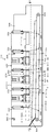
硬貨入出金装置100の概要を図1を参照して説明する。
硬貨入出金装置100は、フレーム101内に配置された入金量規制装置102、分離送出装置104、金種判別装置106、入金搬送装置108、選別部110、硬貨保留部112及び出金装置114、及び、硬貨受取口116を含んでいる。
本願発明は、出金装置114における硬貨搬送案内装置118に関する。
This Example 1 accepts coins of 8 denominations of 2 euros, 1 euro, 50 cents, 20 cents, 10 cents, 5 cents, 2 cents and 1 cent, which are the currencies of the European Community, and holds them for each denomination In this example, it is used as a coin transport guide device for dispensing a coin depositing and dispensing device that dispenses a predetermined number of coins of a predetermined denomination based on a dispensing instruction from the device.
An outline of the coin depositing and dispensing apparatus 100 will be described with reference to FIG.
The coin deposit / withdrawal device 100 includes a deposit amount regulating device 102, a separation / delivery device 104, a denomination discriminating device 106, a deposit / conveyance device 108, a sorting unit 110, a coin holding unit 112, and a
The present invention relates to a coin conveyance guide device 118 in the
まず入金量規制装置102を説明する。
入金量規制装置102は、投入口120にバラ積み状態で投入された複数金種の硬貨Cを、単位時間当たり所定量を超えない範囲で次行程の分離送出装置104に送り出す機能を有する。
具体的には、入金平ベルト122、崩しローラ124及び入金平ベルト122を駆動する第1電気モータ126を含んでいる。
入金平ベルト122は、最大硬貨直径の約二倍の幅を有し、一対のローラ間に張設され、かつ、僅かに上り傾斜に設けられている。
First, the deposit amount regulating apparatus 102 will be described.
The deposit amount regulating device 102 has a function of sending coins C of a plurality of denominations placed in a stacked state into the slot 120 to the separation and delivery device 104 in the next process within a range not exceeding a predetermined amount per unit time.
Specifically, it includes a depositing flat belt 122, a breaking roller 124, and a first electric motor 126 that drives the depositing flat belt 122.
The deposit flat belt 122 has a width of about twice the maximum coin diameter, is stretched between a pair of rollers, and is slightly inclined upward.
この入金平ベルト122は、第1電気モータ126により硬貨を前方に搬送する正転方向及び硬貨を戻す逆転方向に移動可能である。
崩しローラ124は、入金平ベルト122の中間部の上方に、入金平ベルト122との間に最薄硬貨の約3倍の隙間を空けて配置されている。
この崩しローラ124は、入金平ベルト122が搬送方向に進行する場合、その下面が入金平ベルト122の進行方向と逆方向に回転し、入金平ベルト122が戻り方向に移動した場合、静止状態になるよう構成されている。
これにより、入金平ベルト122上に最薄の硬貨が三枚以上重なって崩しローラ124に到達した場合、最上の硬貨は崩しローラ124によって戻り方向に移動されてズリ落とされ、多量の硬貨Cが一気に分離送出装置104に落下しないように規制している。
The deposit flat belt 122 is movable in the forward rotation direction in which coins are conveyed forward by the first electric motor 126 and in the reverse rotation direction in which coins are returned.
The crushing roller 124 is disposed above the intermediate portion of the deposit flat belt 122 with a gap about three times that of the thinnest coin between the deposit flat belt 122.
When the deposit flat belt 122 travels in the transport direction, the crushing roller 124 rotates in the direction opposite to the travel direction of the deposit flat belt 122, and when the deposit flat belt 122 moves in the return direction, It is comprised so that it may become.
Thereby, when three or more thinnest coins overlap on the deposit flat belt 122 and reach the crushing roller 124, the uppermost coin is moved back in the return direction by the crushing roller 124, and a large amount of coins C are dropped. It is restricted so that it does not fall into the separation and delivery device 104 at once.
投入口120の下方の入金平ベルト122の僅か上方をその光軸が横断するよう、入金検知装置である光電センサ128が配置される。
光電センサ128の光軸が遮断された場合、硬貨Cが投入されたとみなし、第1電気モータ126を駆動して入金平ベルト122を入金方向に移動させる。
また、後述の分離送出装置104のフルセンサ136がフル状態を検知した場合、第1電気モータ126は停止される。
したがって、分離送出装置104は、入金量規制装置102からフル量以上の硬貨を受けることが無く、安定して一つずつ区分けして送り出すことができる。
なお、光電センサ128は、入金平ベルト122の下側に設置した磁気センサによって代替えすることが出来る。
A photoelectric sensor 128, which is a deposit detection device, is arranged so that the optical axis crosses slightly above the deposit flat belt 122 below the slot 120.
When the optical axis of the photoelectric sensor 128 is interrupted, it is considered that the coin C has been inserted, and the first electric motor 126 is driven to move the deposit flat belt 122 in the deposit direction.
Further, when the full sensor 136 of the separation / delivery device 104 described later detects the full state, the first electric motor 126 is stopped.
Therefore, the separation and delivery device 104 can receive the coins of the full amount or more from the deposit amount regulating device 102, and can stably send out the coins one by one.
The photoelectric sensor 128 can be replaced by a magnetic sensor installed below the deposit flat belt 122.
次に分離送出装置104を説明する。
分離送出装置104は、入金量規制装置102からバラ積み状態で受け入れた複数金種の硬貨Cを一つずつ分離して次行程へ送り出す機能を有する。
分離送出装置104は、入金量規制装置102の下方に配置され、回転板130、保留ボウル132、受取体134及びフルセンサ136を含んでいる。
Next, the separation / delivery device 104 will be described.
The separation and delivery device 104 has a function of separating coins C of a plurality of denominations received from the deposit amount regulation device 102 in a stacked state one by one and sending them to the next process.
The separation and delivery device 104 is disposed below the deposit amount regulating device 102 and includes a rotating plate 130, a holding bowl 132, a receiving body 134, and a full sensor 136.
回転板130は、硬貨Cを一つずつ受け入れる受入部138を有し、所定の角度で傾斜配置され、かつ、所定の速度で回転される。
受入部138は、回転円板140の上面に等間隔に3つの凹部142を形成したY字形のプレート146を回転円板140と同心に固定してある。
なお、回転円板140の直径を大きくした場合、受入部138の数は4以上にすることが出来、回転円板140の直径を小さくした場合、受入部138の数は2以下にすることが出来る。
凹部142の一側にはピボット運動する押出体148が配置されている(例えば特許第4784806号参照)。
換言すれば、押出体148と凹部142によってほぼ半円形の受入部138が形成されている。
受入部138は、最小径硬貨が二つ並んで受入られることができず、かつ、最大径硬貨が一枚のみ受け入れられる大きさに設定されている。
押出体148は、通常は受入部138を形成するように凹部142の一側に寄った位置に静止状態に位置し、ピボット運動して所定位置に移動した場合、保持されていた硬貨を回転円板140の周方向へ送り出す。
この押出体148の移動は、回転円板140の回転動を利用して溝カムなどで行うことが好ましい。
The rotating plate 130 has a receiving portion 138 that receives the coins C one by one, is inclined at a predetermined angle, and is rotated at a predetermined speed.
In the receiving portion 138, a Y-shaped plate 146 having three concave portions 142 formed at equal intervals on the upper surface of the rotating disk 140 is fixed concentrically with the rotating disk 140.
When the diameter of the rotating disc 140 is increased, the number of receiving portions 138 can be 4 or more, and when the diameter of the rotating disc 140 is decreased, the number of receiving portions 138 can be 2 or less. I can do it.
An extrudate 148 that pivots is disposed on one side of the recess 142 (see, for example, Japanese Patent No. 4784806).
In other words, a substantially semicircular receiving portion 138 is formed by the extruded body 148 and the concave portion 142.
The receiving unit 138 is set to a size that cannot accept two coins having the smallest diameter and that accepts only one coin having the largest diameter.
The extruded body 148 is normally positioned at a position close to one side of the concave portion 142 so as to form a receiving portion 138, and when it moves to a predetermined position by pivoting, the held coin is rotated into a circle. Send out in the circumferential direction of the plate 140
The movement of the extruded body 148 is preferably performed by a groove cam or the like using the rotational movement of the rotating disk 140.
受入部138は、保留ボウル132に相対する下部においてバラ積み状態で保留された硬貨Cを一つずつ受入れ、押出体148は回転板130の回転中心よりも上方の所定の位置において受入部138の硬貨Cを周方向へ押し出し、ナイフ形状の受取体134に受け渡す。
回転板130は図示しない電気モータによって減速機を介して所定の速度で回転される。
The receiving unit 138 receives coins C held one by one in a stacked state in the lower part opposite to the holding bowl 132, and the extruded body 148 of the receiving unit 138 at a predetermined position above the rotation center of the rotating plate 130. Coins C are pushed out in the circumferential direction and delivered to a knife-shaped receiving body 134.
The rotating plate 130 is rotated at a predetermined speed via a speed reducer by an electric motor (not shown).
フルセンサ136は、保留ボウル132内の硬貨量が所定量以上になった場合、フル信号を出力する機能を有し、例えば、透過形の光電センサである。
フルセンサ136がフル信号を出力した場合、第1電気モータ126が停止され、入金量規制装置102からの硬貨Cの供給が停止される。
フルセンサ136がフル信号を出力しなくなった場合、第1電気モータ126は再起動され、入金平ベルト122上の硬貨Cが保留ボウル132に供給される。
The full sensor 136 has a function of outputting a full signal when the amount of coins in the storage bowl 132 exceeds a predetermined amount, and is, for example, a transmissive photoelectric sensor.
When the full sensor 136 outputs a full signal, the first electric motor 126 is stopped, and the supply of the coin C from the deposit amount regulating device 102 is stopped.
When the full sensor 136 stops outputting a full signal, the first electric motor 126 is restarted, and the coin C on the deposit flat belt 122 is supplied to the storage bowl 132.
次に、金種判別装置106が説明される。
金種判別装置106は、分離送出装置104から一つずつ送り出された硬貨Cの真偽及び金種を判別する機能を有する。
金種判別装置106は、硬貨の材質、厚み及び直径等に関する物理情報を磁気センサ150によって取得した検知データに基づいて硬貨Cの真偽及び金種を判別する機能を有する。
Next, the denomination discrimination device 106 will be described.
The denomination discriminating device 106 has a function of discriminating the authenticity and denomination of the coins C sent out one by one from the separation / delivery device 104.
The denomination discriminating device 106 has a function of discriminating the authenticity and denomination of the coin C based on the detection data obtained by the magnetic sensor 150 with respect to physical information relating to the material, thickness, diameter, etc. of the coin.
金種判別装置106は、磁気センサ150、回転円板140の上面と同一平面内に配置されたスライドベース(図示せず)、硬貨Cを送るための回転体152及び基準ガイド154を含んでいる。
スライドベースは、回転体152によって押動される硬貨Cの一面を案内する機能を有する。
回転体152は、分離送出装置104から受け取った硬貨Cを移動させ、一つずつ硬貨受入部158を通過させる機能を有する。
さらに、回転体152は硬貨受入部158を通過した硬貨Cを入金搬送装置108へ受け渡す機能を有する。
回転体152は、スライドベースと平行であって、かつ、近接した平面内において回転可能であり、受入部138と同数の等間隔に配置された三本の押動レバ156によって硬貨受入部158を形成し、Y字形をしている。
基準ガイド154は、硬貨受入部158に相対して通過する硬貨Cを直線的に案内し、磁気センサ150に対する硬貨Cの位置を一定にする機能を有する。
The denomination discriminating device 106 includes a magnetic sensor 150, a slide base (not shown) arranged in the same plane as the upper surface of the rotating disc 140, a rotating body 152 for feeding coins C, and a reference guide 154. .
The slide base has a function of guiding one surface of the coin C pushed by the rotating body 152.
The rotating body 152 has a function of moving the coins C received from the separation and delivery device 104 and passing them through the coin receiving unit 158 one by one.
Further, the rotating body 152 has a function of delivering the coin C that has passed through the coin receiving unit 158 to the depositing / conveying device 108.
The rotating body 152 is parallel to the slide base and can be rotated in an adjacent plane, and the coin receiving unit 158 is moved by the three pushing levers 156 arranged at the same number of intervals as the receiving unit 138. Formed and Y-shaped.
The reference guide 154 has a function of linearly guiding the coin C passing relative to the coin receiving unit 158 and making the position of the coin C relative to the magnetic sensor 150 constant.
次に入金搬送装置108を説明する。
入金搬送装置108は、その真偽及び金種を判別された硬貨Cを選別部110に搬送する機能を有する。
入金搬送装置108は、同一平面内を一方向に移動する無端搬送体160及び無端搬送体160によって押動される硬貨Cの一面がスライドするスライドプレート162及び前記硬貨Cの周面を案内する一直線状のガイドレール164を含んでいる。
スライドプレート162の傾斜角は、硬貨入出金装置100全体を小型化するには、約45度が好ましい。
無端搬送体160は、本実施例において、所定の間隔で配置された第1スプロケット166と第2スプロケット168との間に張設されたチェーン170である。しかし、無端搬送体160はベルトであってもよい。
チェーン170は、扁平なランニングトラック形状に設置され、第1スプロケット166は金種判別装置106の回転体152の直ぐ側方に配置されている。
チェーン170は、金属製チェーンであることが耐久性及びコストの観点で好ましいが、樹脂製にすることができる。
チェーン170の側面に押動ピン172が所定の間隔で固定されている。
Next, the deposit conveyance device 108 will be described.
The deposit transfer device 108 has a function of transporting the coin C whose trueness and denomination have been determined to the sorting unit 110.
The depositing and conveying apparatus 108 includes an endless conveying body 160 that moves in the same plane in one direction, a slide plate 162 on which one surface of the coin C pushed by the endless conveying body 160 slides, and a straight line that guides the peripheral surface of the coin C. Shaped guide rail 164 is included.
The inclination angle of the slide plate 162 is preferably about 45 degrees in order to reduce the size of the coin depositing / dispensing apparatus 100 as a whole.
In the present embodiment, the endless transport body 160 is a chain 170 stretched between a first sprocket 166 and a second sprocket 168 that are arranged at a predetermined interval. However, the endless transport body 160 may be a belt.
The chain 170 is installed in the shape of a flat running track, and the first sprocket 166 is disposed immediately on the side of the rotating body 152 of the denomination determining device 106.
The chain 170 is preferably a metal chain from the viewpoint of durability and cost, but can be made of resin.
Push pins 172 are fixed to the side surface of the chain 170 at a predetermined interval.
押動ピン172は、押動レバ156の間隔に対応した間隔でチェーン170に複数取り付けられている。
第1スプロケット166は所定の速度で回転され、押動レバ156と押動ピン172は、押動レバ156によって押動ピン172の移送経路174に押動された硬貨Cは、直ぐに押動ピン172によって押動されるように設定される。移送経路174は、ガイドレール164によって案内されつつ押動ピン172によって押動される硬貨Cが移動する経路である。
A plurality of push pins 172 are attached to the chain 170 at intervals corresponding to the intervals of the push lever 156.
The first sprocket 166 is rotated at a predetermined speed, and the pushing lever 156 and the pushing pin 172 are immediately pushed into the transfer path 174 of the pushing pin 172 by the pushing lever 156. Is set to be pushed. The transfer path 174 is a path along which the coin C pushed by the push pin 172 moves while being guided by the guide rail 164.
ガイドレール164は、押動ピン172によって押される硬貨Cが移送経路174を移動するよう、硬貨Cの下端周面を案内する機能を有する。
ガイドレール164は、ランニングトラック形の上側の直線状を呈するチェーン170に沿って、かつ、その僅か下方に配置される。
ガイドレール164は、前記スライドプレート162に対し、取扱硬貨の最大厚みよりも僅かに直交方向に突出している。
したがって、押動ピン172によって押される硬貨Cは、その下面がスライドプレート162によって案内され、かつ、下端周面はガイドレール164によって案内される。
本実施例1におけるガイドレール164は、後述するように、選別部も兼ねている。
The guide rail 164 has a function of guiding the lower peripheral surface of the coin C so that the coin C pushed by the push pin 172 moves on the transfer path 174.
The guide rail 164 is disposed along and slightly below the chain 170 having an upper straight shape of the running track shape.
The guide rail 164 protrudes slightly in the orthogonal direction with respect to the slide plate 162 with respect to the maximum thickness of the handling coins.
Therefore, the lower surface of the coin C pushed by the push pin 172 is guided by the slide plate 162, and the lower peripheral surface thereof is guided by the guide rail 164.
As will be described later, the guide rail 164 in the first embodiment also serves as a selection unit.
選別部110は、硬貨Cを金種毎に所定の硬貨選別孔に落下させる機能を有している。
選別部110は、ガイドレール164の上側にガイドレール164に沿って配置された上側選別部180、及び、ガイドレール164に沿って下側に配置された下側選別部182を有している。
The sorting unit 110 has a function of dropping the coin C into a predetermined coin sorting hole for each denomination .
The sorting unit 110 includes an upper sorting unit 180 disposed along the guide rail 164 on the upper side of the guide rail 164 and a lower sorting unit 182 disposed on the lower side along the guide rail 164.
上側選別部180は、入金搬送装置108の進行方向に向かって順に2セント硬貨選別孔184、5セント硬貨選別孔186、10セント硬貨選別孔188、20セント硬貨選別孔190及びオーバーフロー硬貨選別孔192が配置されている。
下側選別部182は、入金搬送装置108の進行方向に向かって順にリジェクト硬貨選別孔194、1セント硬貨選別孔196、2ユーロ硬貨選別孔198、50セント硬貨選別孔200及び1ユーロ硬貨選別孔202が配置されている。
このように、入金搬送装置108の上側選別部180と下側選別部182を配置した場合、入金搬送装置108の同一場所で上側と下側に硬貨Cを振り分けできるので、硬貨の搬送距離を短くでき、硬貨入出金装置100を小型化できる利点がある。
なお、各硬貨選別孔に対する金種の配置は一例であるので、必要に応じ自由に配置できる。
The upper sorting unit 180 includes a 2 cent coin sorting hole 184, a 5 cent coin sorting hole 186, a 10 cent coin sorting hole 188, a 20 cent coin sorting hole 190, and an overflow coin sorting hole 192 in order in the direction of travel of the deposit conveyance device 108. Is arranged.
The lower sorting unit 182 includes a reject coin sorting hole 194, a 1 cent coin sorting hole 196, a 2 euro coin sorting hole 198, a 50 cent coin sorting hole 200, and a 1 euro coin sorting hole in order toward the traveling direction of the deposit transfer device 108. 202 is arranged.
As described above, when the upper sorting unit 180 and the lower sorting unit 182 of the deposit conveyance device 108 are arranged, the coins C can be distributed to the upper side and the lower side in the same place of the deposit conveyance device 108, so the coin conveyance distance is shortened. There is an advantage that the coin depositing and dispensing apparatus 100 can be downsized.
In addition, since arrangement | positioning of the money type with respect to each coin selection hole is an example, it can arrange | position freely as needed.
各硬貨選別孔184、186、188、190、192、194、196、198、200及び202には、電気的アクチュエータによって作動されるゲート装置(図示せず)が配置されている。
本実施例1において、硬貨選別孔194、196、198、200及び202のゲート装置は、ガイドレール164も兼ねている。
すなわち、ガイドレール164は、リジェクト硬貨選別孔194、1セント硬貨選別孔196、2ユーロ硬貨選別孔198、50セント硬貨選別孔200及び1ユーロ硬貨選別孔202の間に固定される固定ガイド、及び、電動的に移動される可動ガイドによって構成され、通常1本の直線状を呈している。
そして、搬送される硬貨が硬貨選別孔194、196、198、200及び202に落下される場合、可動ガイドを通常の位置から移動させることにより、移送される硬貨が可動ガイドに案内されないようにし、所定の硬貨選別孔に落下するようにしてある(特許第4997374参照)。
In each of the coin sorting holes 184, 186 , 188, 190 , 192, 194 , 196 , 198 , 200 and 202, a gate device (not shown) operated by an electric actuator is arranged.
In the first embodiment, the gate device of the coin sorting holes 194, 196, 198, 200 and 202 also serves as the guide rail 164.
That is, the guide rail 164 is a fixed guide fixed between the reject coin sorting hole 194, the 1 cent coin sorting hole 196, the 2 euro coin sorting hole 198, the 50 cent coin sorting hole 200, and the 1 euro coin sorting hole 202, And it is comprised by the movable guide moved electrically, and normally exhibits one linear form.
And when the coins to be transported are dropped into the coin sorting holes 194, 196, 198, 200 and 202, by moving the movable guide from the normal position, the transferred coins are not guided to the movable guide, It falls into a predetermined coin sorting hole (see Japanese Patent No. 4997374).
各硬貨選別孔184、186、188、190、192、194、196、198、200及び202に相対するゲート装置は、タイミングセンサ(図示せず)からのタイミング信号、及び、硬貨受入部158によって検知された硬貨情報によって判別された真偽及び金種に基づいて選択的に開閉される。
結果として、入金搬送装置108によって搬送される硬貨Cは、金種毎に所定の硬貨選別孔に落下させられる。
Each coin sorting holes 184,186,188,190, 192, opposite the gate device 194,196,198,200 and 202, the timing signal from the timing sensor (not shown), and, by hard 貨受 join the club 158 It is selectively opened and closed based on the authenticity and denomination determined by the detected coin information.
As a result, the coin C transported by the deposit transport device 108 is dropped into a predetermined coin sorting hole for each denomination .
硬貨保留部112は、選別部110において金種毎に選別された硬貨Cを金種別に保留する機能を有する。
本実施例1において、硬貨保留部112は回転ディスクによって硬貨Cを一つずつ払い出す硬貨払出装置210を金種毎に選別部110の下方に上側選別部180及び下側選別部182に相対して横並びに並列した第1硬貨払出装置列212及び第2硬貨払出装置列214の二列に並べることにより構成されている。
なお、第1硬貨払出装置列212及び第2硬貨払出装置列214における「第1」及び「第2」は区別のために付与したものであり、権利解釈上特に意味を有するものではない。
各硬貨払出装置210は、符号210に金種を付して表示してある。
The coin holding unit 112 has a function of holding the coins C sorted for each denomination in the sorting unit 110 for each denomination.
In the first embodiment, the coin holding unit 112 has a coin dispensing device 210 that pays out coins C one by one by means of a rotating disk, relative to the upper sorting unit 180 and the lower sorting unit 182 below the sorting unit 110 for each denomination. The first coin dispensing device row 212 and the second coin dispensing device row 214 are arranged side by side in parallel.
Note that “first” and “second” in the first coin dispensing device row 212 and the second coin dispensing device row 214 are given for distinction, and have no particular meaning in interpretation of rights.
Each coin dispensing device 210 is displayed with a denomination added to reference numeral 210.
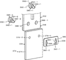
第1硬貨払出装置列212及び第2硬貨払出装置列214を構成する硬貨払出装置210の一例が図2〜4を参照して説明される。
硬貨払出装置210は、保留する硬貨Cを一つずつ区分けして払い出す機能及び払い出した硬貨Cの検知信号を出力する機能を有する。
硬貨払出装置210は、硬貨Cを保留するための筒状の保留ボウル216、保留ボウル216の底部に配置され、硬貨Cを一つずつ区分けするための回転ディスク218、回転ディスク218によって連れ回りされる硬貨Cがスライドする平板状のベース220、回転ディスク218を回転駆動するための第2電気モータ222、及び、硬貨Cを弾き出す投出装置224及び後述の硬貨検知装置226を含んでいる。
An example of the coin dispensing device 210 constituting the first coin dispensing device row 212 and the second coin dispensing device row 214 will be described with reference to FIGS.
The coin dispensing device 210 has a function of sorting and dispensing the held coins C one by one and a function of outputting a detection signal of the dispensed coins C.
The coin dispensing device 210 is disposed at the bottom of the cylindrical holding bowl 216 for holding the coin C and the holding bowl 216, and is rotated by the rotating disk 218 and the rotating disk 218 for sorting the coins C one by one A flat base 220 on which a coin C slides, a second electric motor 222 for rotating the rotating disk 218, a dispensing device 224 for ejecting the coin C, and a coin detecting device 226 described later.
まず、保留ボウル216を説明する。
保留ボウル216は、全体として縦向きの筒形をし、上端部はほぼ矩形であり、下端部は円形の底孔230であり、硬貨Cをばら積み状態で多数保留する機能を有する。
保留ボウル216は、後述のベースフレーム232の上面に着脱可能に取り付けられている。
First, the holding bowl 216 will be described.
The retaining bowl 216 has a vertically-oriented cylindrical shape as a whole, the upper end is substantially rectangular, and the lower end is a circular bottom hole 230, and has a function of retaining a large number of coins C in a stacked state.
The storage bowl 216 is detachably attached to the upper surface of a base frame 232 described later.
次に、回転ディスク218を説明する。
回転ディスク218は、保留ボウル216内の硬貨Cを攪拌すると共に硬貨Cを一つずつ区分けする機能を有する。
回転ディスク218は、保留ボウル216の下方のベースフレーム232の円形孔234内に傾斜状態で回転自在に配置されている。
回転ディスク218は、所定の間隔で複数配置された通孔236、上面中央部に錐形の攪拌部238及びその下面に硬貨Cの第1押出部240、及び、第2押動部242を有する。
Next, the rotating disk 218 will be described.
The rotating disk 218 has a function of stirring the coins C in the storage bowl 216 and sorting the coins C one by one.
The rotating disk 218 is rotatably disposed in an inclined state in a circular hole 234 of the base frame 232 below the storage bowl 216.
The rotating disk 218 has a plurality of through holes 236 arranged at predetermined intervals, a conical stirring portion 238 at the center of the upper surface, a first pushing portion 240 of coins C on the lower surface, and a second pushing portion 242. .
したがって、通孔236に落下した硬貨Cは、ベース220の上面244に保持され、かつ、硬貨払出時は図4において反時計方向に正転する回転ディスク218裏面の第1押出部240によって押動され、円形孔234に周縁を案内されつつ回転ディスク218と共に反時計方向に回動される。
連れ回りされる硬貨Cは、ベース220の上面244の所定位置に突出しているピン246、248によって移動が阻止されると共に、回転ディスク218の周方向へ案内される。
Accordingly, the coin C that has fallen into the through hole 236 is held by the upper surface 244 of the base 220 and is pushed by the first pushing portion 240 on the back surface of the rotating disk 218 that rotates forward counterclockwise in FIG. Then, it is rotated counterclockwise together with the rotating disk 218 while the periphery of the circular hole 234 is guided.
The coin C to be rotated is prevented from moving by the pins 246 and 248 protruding to predetermined positions on the upper surface 244 of the base 220 and is guided in the circumferential direction of the rotating disk 218.
この位置の円形孔234は切欠かれ、払出開口250が形成されているので、押し出された硬貨Cは、円形孔234の外へ移動することができる。
ピン246、248は、スプリング(図示せず)によりベース220の下方から上面244に突出するよう付勢され、かつ、回転ディスク218の正転方向に相対する反対側の上端部に斜面252、254が形成されている。
Since the circular hole 234 at this position is notched and the dispensing opening 250 is formed, the pushed coin C can move out of the circular hole 234.
The pins 246 and 248 are urged by a spring (not shown) so as to protrude from the lower side of the base 220 to the upper surface 244, and the inclined surfaces 252 and 254 Is formed.
これにより、回転ディスク218が逆転した場合、硬貨Cによって斜面252、254が押されるため、ピン246、248はスプリング力に反して下方に押し下げられる。
よって、硬貨Cはピン246、248を乗り越えて回転ディスク218と共に時計方向に移動し、払出開口250から払い出されることが無い。
As a result, when the rotating disk 218 reverses, the slopes 252 and 254 are pushed by the coin C, so that the pins 246 and 248 are pushed down against the spring force.
Therefore, the coin C gets over the pins 246 and 248 and moves in the clockwise direction together with the rotating disk 218 and is not paid out from the payout opening 250.
また、回転ディスク218は、ベース220を貫通して回転自在に取り付けられた回転軸256の上端部にその軸線方向にスライド不能かつ回転軸256に対して回転不能に取り付けられる。
詳述すれば、回転ディスク218とベース220の上面244との間に低摩擦係数を有するシムを介在させることにより、それらの間の距離を調整し、硬貨Cの厚みに応じた回転ディスク218の位置に調整することができる。
なお、硬貨Cの厚みに対する回転ディスク218の位置調整装置は、前述のシムの他、同一機能を有する他の装置に変更することができる。
Further, the rotating disk 218 is attached to the upper end portion of the rotating shaft 256 that is rotatably attached through the base 220 and is not slidable in the axial direction and is not rotatable with respect to the rotating shaft 256.
Specifically, by interposing a shim having a low coefficient of friction between the rotating disk 218 and the upper surface 244 of the base 220, the distance between them is adjusted, and the rotating disk 218 according to the thickness of the coin C is adjusted. Can be adjusted to the position.
The position adjusting device for the rotary disk 218 with respect to the thickness of the coin C can be changed to another device having the same function in addition to the above-described shim.
次にベース220を説明する。
ベース220は、回転ディスク218によって連れ回りされる硬貨Cを平らな上面244で案内する機能を有する。
ベース220は矩形箱形のベースフレーム232の上面中央の円形孔234内に固定され、約30度から40度の範囲で払出開口250側が高くなるように傾斜している。
この傾斜角度は、より小さい方が保留ボウル216の硬貨保留量が大きいので好ましい。
しかし、傾斜角度が小さい場合、回転ディスク218の直径の硬貨払出装置210の大きさに対する影響度が増加するため、傾斜角度は約30度が最小であり、傾斜角度が大きい場合、硬貨の払出効率が落ちるため、約60度が最大である。
円形孔234と保留ボウル216の下端部の底孔230とは同一径に形成され、一体化されている。
ベースフレーム232は、箱形であり、内部の空間に第2電気モータ222等が配置されている。
Next, the base 220 will be described.
The base 220 has a function of guiding the coin C rotated by the rotating disk 218 with a flat upper surface 244.
The base 220 is fixed in a circular hole 234 in the center of the upper surface of the rectangular box-shaped base frame 232, and is inclined so that the payout opening 250 side becomes higher in a range of about 30 to 40 degrees.
A smaller inclination angle is preferable because the amount of coins retained in the retaining bowl 216 is large.
However, when the tilt angle is small, the influence of the diameter of the rotating disk 218 on the size of the coin dispensing device 210 increases, so the tilt angle is about 30 degrees minimum, and when the tilt angle is large, the coin dispensing efficiency The maximum is about 60 degrees.
The circular hole 234 and the bottom hole 230 at the lower end of the storage bowl 216 are formed to have the same diameter and are integrated.
The base frame 232 has a box shape, and the second electric motor 222 and the like are arranged in the internal space.
次に第2電気モータ222を説明する。
第2電気モータ222は、回転ディスク218を正転方向及び逆転方向に回転する機能及び回転ディスク218を停止する機能を有する。
第2電気モータ222は、ベースフレーム232の内部空間に配置されている。
第2電気モータ222は、電気モータ、エアモータ、オイルモータ等使用可能であるが、電気モータが小型化、制御のし易さから最も好ましい。
第2電気モータ222は、電源が直流又は交流であってもよく、更にモータ形式として誘導モータ等各種使用可能であるが、正逆転可能であり、小型化、メンテナンス性及び耐久性の観点からブラシレスDCモータが好ましい。
第2電気モータ222は、上位の制御装置(図示せず)からの指令により、硬貨Cを払い出すための正転、硬貨ジャムを解消するための逆転、及び、正又は逆転時に逆方向の回転力を一瞬作用させて急速停止する停止を行う。
第2電気モータ222の出力軸(図示せず)は、減速機構(図示せず)を介してベースフレーム232に垂立状態で回転自在に取り付けられた回転軸256を回転させる。
したがって、回転ディスク218は、第2電気モータ222の正転により正転方向へ回転され、逆転により逆転方向へ回転され、第2電気モータ222の停止により回転が停止される。
Next, the second electric motor 222 will be described.
The second electric motor 222 has a function of rotating the rotating disk 218 in the forward direction and the reverse direction and a function of stopping the rotating disk 218.
The second electric motor 222 is disposed in the internal space of the base frame 232.
As the second electric motor 222, an electric motor, an air motor, an oil motor, or the like can be used. However, the electric motor is most preferable from the viewpoint of downsizing and ease of control.
The second electric motor 222 may be a direct current or an alternating current power source, and various types of motors such as an induction motor can be used. A DC motor is preferred.
The second electric motor 222 is rotated in the forward direction for paying out the coin C, the reverse rotation for eliminating the coin jam, and the reverse rotation during the forward or reverse rotation according to a command from a host control device (not shown). A stop is applied to apply a force for a moment and then stop rapidly.
An output shaft (not shown) of the second electric motor 222 rotates a rotary shaft 256 that is rotatably attached to the base frame 232 in a vertical state via a speed reduction mechanism (not shown).
Accordingly, the rotating disk 218 is rotated in the forward direction by the normal rotation of the second electric motor 222, is rotated in the reverse direction by the reverse rotation, and the rotation is stopped by the stop of the second electric motor 222.
次に投出装置224を説明する。
投出装置224は、硬貨Cを一つずつ所定方向へ投出する機能を有する。
本実施例1において投出装置224は、回転ディスク218により一つずつ送り出される硬貨Cを所定方向へ勢いを付けて投出する機能を有する。
投出装置224は、回転ディスク218に隣接し、払出開口250に相対して配置されている。
投出装置224は、一方がベース220に対し実質的に固定状態に配置された固定案内体258としての固定ローラ260とベース220に対し移動可能に配置され、かつ、固定案内体258側に近づくよう付勢された可動案内体262としての可動ローラ264により構成され、硬貨Cの直径部がそれらローラ間を通過した直後、可動ローラ264に付勢装置266によって付加されている付勢力により、硬貨Cは勢いよく弾き出される。
投出装置224の硬貨Cの投出方向は、図4における矢印Xの弾出方向線方向(以下、弾出方向線X方向と記載する。)を指向している。しかし、硬貨Cの投出方向は、弾出方向線X方向に限らず、硬貨Cと固定ローラ260及び可動ローラ264とによる挟み状況等によって様々に変化する。
Next, the dispensing device 224 will be described.
The dispensing device 224 has a function of dispensing coins C one by one in a predetermined direction.
In the first embodiment, the dispensing device 224 has a function of throwing out coins C fed one by one by the rotating disk 218 in a predetermined direction.
The dispensing device 224 is adjacent to the rotary disk 218 and is disposed relative to the dispensing opening 250.
One of the dispensing devices 224 is arranged so as to be movable with respect to the fixed roller 260 and the base 220 as a fixed guide body 258 arranged in a substantially fixed state with respect to the base 220, and approaches the fixed guide body 258 side. The urging force applied to the movable roller 264 by the urging device 266 immediately after the diameter portion of the coin C passes between the rollers is constituted by the movable roller 264 as the movable guide body 262 that is urged. C is played vigorously.
The throwing direction of the coin C of the throwing device 224 is directed in the direction of the projecting direction of the arrow X in FIG. 4 (hereinafter referred to as the direction of projecting direction X) . However, the direction in which the coin C is thrown out is not limited to the direction X of the ejection direction, but varies depending on the pinching state between the coin C and the fixed roller 260 and the movable roller 264.
次に付勢装置266を説明する。
付勢装置266は、可動案内体262に所定の付勢力を付加する機能を有する。
付勢装置266は、先端に可動ローラ264が回転自在に取り付けられたレバー268が固定軸269にピボット運動可能に取り付けられ、レバー268が弦巻スプリング270によって固定ローラ260に近づくよう付勢されている。したがって、弦巻スプリング270が付勢装置266である。
レバー268は、可動ローラ264が回転ディスク218に近接した位置においてストッパ272によって係止され、待機位置SP(図4に示す位置)に保持される。
Next, the biasing device 266 will be described.
The urging device 266 has a function of applying a predetermined urging force to the movable guide body 262.
In the biasing device 266, a lever 268 having a movable roller 264 rotatably attached to the tip is attached to a fixed shaft 269 so as to be pivotable, and the lever 268 is biased by a string spring 270 so as to approach the fixed roller 260. . Therefore, the string spring 270 is the biasing device 266.
The lever 268 is locked by a stopper 272 at a position where the movable roller 264 is close to the rotating disk 218, and is held at the standby position SP (position shown in FIG. 4).
可動ローラ264が待機位置SP位置する場合、固定ローラ260と可動ローラ264の間隔は、払い出すべき硬貨Cの直径よりも小さく設定されている。
一方、ピン246、248に案内されつつ第1押出部240によって回転ディスク218の円周方向に押し出された硬貨Cは、一側を固定ローラ260に案内されるため、可動ローラ264を図4において時計方向に回動させることから、レバー268は時計方向に回動される。
レバー268の時計方向の回動に伴って弦巻スプリング270の弾発力が蓄積される。
硬貨Cの直径部が固定ローラ260と可動ローラ264との間を通過した直後、弦巻スプリング270に蓄積された弾発力によってレバー268が反時計方向へ急速に回動されるため、硬貨Cは弾出方向線X方向へ弾かれ、払出開口250及び硬貨放出位置296並びに硬貨放出口311を通って払出空間274へ投出される。
詳細には、硬貨Cは傾斜したベース220に沿って弾き出されるため、斜め上向きに投出され、後述の検知通路282に向かって進行し、希にではあるが跳ね返り体276に衝突して跳ね返って後、払い出される。
When the movable roller 264 is at the standby position SP, the interval between the fixed roller 260 and the movable roller 264 is set smaller than the diameter of the coin C to be dispensed.
On the other hand, since the coin C pushed in the circumferential direction of the rotary disk 218 by the first pushing portion 240 while being guided by the pins 246 and 248 is guided to the fixed roller 260 on one side, the movable roller 264 is shown in FIG. Since the lever 268 is rotated clockwise, the lever 268 is rotated clockwise.
As the lever 268 rotates in the clockwise direction, the elastic force of the string winding spring 270 is accumulated.
Immediately after the diameter portion of the coin C passes between the fixed roller 260 and the movable roller 264, the lever 268 is rapidly rotated counterclockwise by the elastic force accumulated in the string winding spring 270. It is bounced in the direction X of the ejection direction and is thrown into the dispensing
Specifically, since the coin C is flipped along the inclined base 220, it is thrown upward obliquely, proceeds toward a detection passage 282 described later, and rarely collides with the rebound body 276 and bounces back. Later, it will be paid out.
次に硬貨検知装置226を説明する。
硬貨検知装置226は、投出装置224によって投出された硬貨Cを検知し、硬貨信号CSを出力する機能を有する。
硬貨検知装置226は、回転ディスク218の回転及び投出装置224によって一つずつ投出された硬貨Cを非接触で検知し、硬貨信号CSを上位の制御装置、例えばPOSレジスタ(図示せず)及び自己の制御回路に出力する。自己の制御装置においては、上位の制御装置から指定された数の硬貨信号CSの数を検知した場合、硬貨の過払出を防止するため、第2電気モータ222への給電を停止する。に出力する。
硬貨検知装置226は、光電式、電磁気式、音波式等を使用することができるが、メンテナンスフリーの観点からゴミや埃等の影響を受けにくい電磁気式硬貨検知装置278を用いることが好ましい。
電磁気式硬貨検知装置278は、投出装置224の側方のベースフレーム232に後述のブラケット280を介して取り付けられている。
Next, the coin detector 226 will be described.
The coin detection device 226 has a function of detecting the coin C thrown out by the dispensing device 224 and outputting a coin signal CS.
Coin detecting device 226, the coin C that is one by one dispensing by rotation and dispensing apparatus 224 of the rotating disk 218 is detected without contact, a higher-order control device of the coin signal CS, for example, without POS register (shown ) And its own control circuit. In its own control device, when the number of coin signals CS designated by the host control device is detected, power supply to the second electric motor 222 is stopped in order to prevent overcoating of coins. Output to.
As the coin detection device 226, a photoelectric method, an electromagnetic method, a sound wave method, or the like can be used, but it is preferable to use an electromagnetic coin detection device 278 that is not easily affected by dust or dust from the viewpoint of maintenance-free.
The electromagnetic coin detecting device 278 is attached to a base frame 232 on the side of the dispensing device 224 via a bracket 280 described later.
次に電磁気式硬貨検知装置278を説明する。
電磁気式硬貨検知装置278は、棒状であって且つ下側にほぼ水平に配置された下側検知部と、当該下側検知部に対し所定の間隔で並設した上側検知部とを含み、下側検知部と上側検知部とが上下方向に延びる接続部によって接続され、上検知部と下検知部との間に横向き門形の検知通路282を有することにより全体的にチャンネル形に形成されている。
下側検知部の上面は、ベースフレーム232の上面と同一平面内に位置している。
検知通路282は、投出装置224によって投出された硬貨Cの進行経路を内包するように配置される。
硬貨Cの投出方向がずれた場合、硬貨Cは下側検知部の上面及び上側検知部の下面、及び、跳ね返り体276に案内されつつ進行する。
下側検知部及び上側検知部には、硬貨検知用のセンサ284が対向配置されている。
電磁気式硬貨検知装置278の場合、磁気コイルが配置され、光電式硬貨検知装置の場合、投受光器が配置される。
電磁気式硬貨検知装置278は、ベースフレーム232の側面に固定された金属製のブラケット280に固定されている。
Next, the electromagnetic coin detector 278 will be described.
The electromagnetic coin detection device 278 includes a lower detection unit that is rod-shaped and substantially horizontally disposed on the lower side, and an upper detection unit that is arranged in parallel with the lower detection unit at a predetermined interval. The side detection part and the upper detection part are connected by a connecting part extending in the up-down direction, and a channel-shaped detection passage 282 is formed between the upper detection part and the lower detection part, so that the channel is formed in a channel shape as a whole. Yes.
The upper surface of the lower detection unit is located in the same plane as the upper surface of the base frame 232.
The detection passage 282 is disposed so as to include the traveling path of the coin C thrown out by the dispensing device 224.
When the throwing direction of the coin C shifts, the coin C advances while being guided by the upper surface of the lower detection unit, the lower surface of the upper detection unit, and the rebound member 276.
A coin detection sensor 284 is disposed opposite to the lower detection unit and the upper detection unit.
In the case of the electromagnetic coin detection device 278, a magnetic coil is arranged, and in the case of the photoelectric coin detection device, a projector / receiver is arranged.
The electromagnetic coin detection device 278 is fixed to a metal bracket 280 fixed to the side surface of the base frame 232.
次に跳ね返り体276を説明する。
跳ね返り体276は、投出装置224で投出された硬貨Cが衝突し、跳ね返らせる機能を有する。
跳ね返り体276は、ブラケット280の一部を突出させることにより、矩形の平板状に形成されている。
跳ね返り体276は、電磁気式硬貨検知装置278の検知通路282に挿入され、接続部の側面に隣接配置してある。
換言すれば、跳ね返り体276は検知通路282の奥部に配置され、接続部の側面を全面的に覆っている。
なお、跳ね返り体276は、接続部の側面に固定し、電磁気式硬貨検知装置278と一体化することができる。
Next, the rebound body 276 will be described.
The rebound body 276 has a function of causing the coins C thrown out by the throwing device 224 to collide and rebound.
The rebound member 276 is formed in a rectangular flat plate shape by projecting a part of the bracket 280.
The rebound member 276 is inserted into the detection passage 282 of the electromagnetic coin detection device 278 and is disposed adjacent to the side surface of the connection portion.
In other words, the rebound member 276 is disposed at the back of the detection passage 282 and covers the entire side surface of the connection portion.
The rebound member 276 can be fixed to the side surface of the connecting portion and integrated with the electromagnetic coin detecting device 278.
上記した硬貨払出装置210は、第2電気モータ222が回転し、減速機構を介して回転ディスク218が図4において反時計方向に回転される。
この回転によって、通孔236に落下した硬貨Cは第1押出部240によって押動されて連れ回りされる。
硬貨Cは連れ回りされる途上において、ピン246、248によって回転ディスク218の円周方向へ案内され、投出装置224によって弾き出される。
このとき硬貨Cは、ベース220によって案内されるので、ベース220の傾斜に基づいて、斜め上方に向かって大凡弾出方向線X方向へ弾き出される。しかしながら、硬貨Cの弾出方向は、各種条件により、ばらつきが大きい。
In the coin dispensing device 210 described above, the second electric motor 222 rotates, and the rotating disk 218 rotates counterclockwise in FIG. 4 via the speed reduction mechanism.
As a result of this rotation, the coin C that has fallen into the through hole 236 is pushed by the first pushing portion 240 and is rotated.
The coin C is guided in the circumferential direction of the rotating disk 218 by the pins 246 and 248 on the way of being rotated, and is ejected by the throwing device 224.
At this time, since the coin C is guided by the base 220, the coin C is flipped out in the direction of the generally projecting direction line X in an obliquely upward direction based on the inclination of the base 220. However, the ejection direction of the coin C varies greatly depending on various conditions.
弾き出された硬貨Cの一部は、検知通路282に進行し、跳ね返り体276に鋭角の入射角で衝突する。
衝突した硬貨Cは、所定の方向、すなわち、入射角とほぼ同一角度で跳ね返される。
硬貨Cがセンサ284に相対した場合、電磁気式硬貨検知装置278は硬貨信号CSを出力する。
A part of the coin C that has been ejected proceeds to the detection path 282 and collides with the rebound body 276 at an acute incident angle.
The collided coin C is bounced back in a predetermined direction, that is, at substantially the same angle as the incident angle.
When the coin C faces the sensor 284, the electromagnetic coin detector 278 outputs a coin signal CS.
第1硬貨払出装置列212と第2硬貨払出装置列214とに属する各硬貨払出装置210は、硬貨受取口116からの距離が同一になるように位置関係が設定してある。
本実施例1においては、図5に示すように、5セント用硬貨払出装置210-5Cと1セント用の硬貨払出装置210-1Cは第1硬貨払出装置対292-1を構成し、硬貨受取口116から同一の第1距離L1に設置されている。
さらに、硬貨搬送案内装置118(払出空間274)を挟んで5セント用硬貨払出装置210-5Cと1セント用の硬貨払出装置210-1Cとが対向配置され、それらの払出開口250は、硬貨搬送案内装置118、換言すれば、後述の搬送ベルト302の伸長方向線Lに沿ってずれている。伸長方向線Lとは、説明の便のために搬送ベルト302の伸長方向に沿って表した直線であって、例えば、搬送ベルト302の幅方向の中心線であってもよい。したがって、図8に示すように、それら払出開口250に対応して第1案内壁306、第2案内壁308に形成された硬貨放出口311もずれて配置されるが、それらの一部はオーバーラップしている。各硬貨Cに対応する硬貨放出口311は、符号311に各金種を付加して表示してある。
同様に、2ユーロ用の硬貨払出装置210-2Eと10セント用の硬貨払出装置210-10Cとは一組の第2硬貨払出装置対292-2を構成し、硬貨受取口116から同一の第2距離L2に設置されている。
20セント用硬貨払出装置210-20Cと50セント用の硬貨払出装置210-50Cとは一組の第3硬貨払出装置対292-3を構成し、硬貨受取口116から同一の第3距離L3に設置されている。
さらに、1ユーロ用硬貨払出装置210-1EとオーバーフローボックスOFとは一組の第4硬貨払出装置対292-4を構成し、硬貨受取口116から同一の第4距離L4に設置されている。このように硬貨払出装置210を硬貨受取口116から同一の距離において対向配置することで硬貨入出金装置100の大きさを小型にできる利点がある。
The positional relationship between the coin dispensing devices 210 belonging to the first coin dispensing device row 212 and the second coin dispensing device row 214 is set so that the distance from the coin receiving port 116 is the same.
In the first embodiment, as shown in FIG. 5, a 5-cent coin dispensing device 210-5C and a 1-cent coin dispensing device 210-1C constitute a first coin dispensing device pair 292-1 and receive a coin. It is installed at the same first distance L1 from the mouth 116.
Furthermore, a coin dispenser 210-5C for 5 cents and a coin dispenser 210-1C for 1 cent are arranged opposite to each other with the coin conveyance guide device 118 (dispensing space 274) in between, and their dispensing opening 250 is configured to convey coins. The guide device 118, in other words, is shifted along the extension direction line L of the later-described
Similarly, the coin dispensing device 210-2E for 2 euros and the coin dispensing device 210-10C for 10 cents constitute a pair of second coin dispensing device pair 292-2, and the same first It is installed at 2 distance L2.
The coin dispenser 210-20C for 20 cents and the coin dispenser 210-50C for 50 cents constitute a pair of third coin dispenser pair 292-3, and the same third distance L3 from the coin receiving port 116. is set up.
Further, the 1 euro coin dispensing device 210-1E and the overflow box OF constitute a pair of fourth coin dispensing device pair 292-4, and are installed at the same fourth distance L4 from the coin receiving port 116. Thus, by disposing the coin dispensing device 210 oppositely from the coin receiving port 116 at the same distance, there is an advantage that the size of the coin depositing / dispensing device 100 can be reduced.
次に出金装置114を説明する。
出金装置114は、金種毎の硬貨払出装置210から放出された硬貨Cを可及的速やかに硬貨受取口116へ搬送する機能を有する。
詳述すれば、出金装置114は硬貨払出装置210から弾き出された硬貨Cの挙動を早期に収束させて搬送ベルト302の上面に速やかに面接触させ、当該搬送ベルト302によって硬貨受取口116へ搬送する機能を有し、本実施例1においては、硬貨搬送案内装置118、緩衝装置300、及び、搬送ベルト302を含んでいる。
Next, the
The
More specifically, the
まず硬貨搬送案内装置118を説明する。
硬貨搬送案内装置118は、硬貨払出装置210から放出された硬貨Cを搬送ベルト302上に案内すると共に、搬送ベルト302によって搬送される硬貨Cを案内する機能を有し、本実施例1では一対の案内壁304たる第1案内壁306及び第2案内壁308によって構成されている。
詳述すれば、第1案内壁306及び第2案内壁308は、硬貨受取口116から遠い下部は下方ほど相対する第1案内壁306又は第2案内壁308に向かって順次近づくように傾斜すると共に、硬貨受取口116に近づくほど第1案内壁306又は第2案内壁308から遠ざかるように形成されている。
本実施例1において、第1案内壁306及び第2案内壁308は同一構造であって、左右対称に配置されているだけであるので、第1案内壁306を代表して説明し、同一符号における-1を-2に置き換えて説明する。
第1案内壁306は、搬送ベルト302に対して垂立する第1垂立案内壁310-1、及び、断面直角三角形であって、第1垂立案内壁310-1に沿って延在している第1倒し体312-1の第1斜面314-1によって形成されている。
First, the coin conveyance guide device 118 will be described.
The coin transport guide device 118 has a function of guiding the coin C released from the coin dispensing device 210 onto the
More specifically, the
In the first embodiment, since the
The
まず、第1垂立案内壁310-1を図6及び図7を参照して説明する。
第1垂立案内壁310-1は、横長矩形の平板であり、コストとの兼ね合いから亜鉛めっき鋼板を採用するのが好ましい。
第1垂立案内壁310-1は第1硬貨払出装置列212及び搬送ベルト302に沿って配置され、搬送ベルト302の上面に対し垂立するように配置される。垂立とは大凡垂立という程度であり、厳密な意味での垂立ではない。
第1垂立案内壁310-1の払出開口250の上面244に沿った延長上には、横長矩形の硬貨放出口311が形成されている。
換言すれば、第1垂立案内壁310-1と第2垂立案内壁310-2は所定の間隔で搬送ベルト302上において平行に垂立し、それらで囲んだ空間が搬送ベルト302の伸長方向に長い、箱形の払出空間274である。
したがって、硬貨放出口311を硬貨払出装置210によって弾き出された硬貨Cが通過して払出空間274に達する。
First, the first vertical guide wall 310-1 will be described with reference to FIGS.
The first vertical guide wall 310-1 is a horizontally long rectangular flat plate, and it is preferable to use a galvanized steel sheet in view of cost.
The first vertical guide wall 310-1 is disposed along the first coin dispensing device row 212 and the
On the extension along the upper surface 244 of the dispensing opening 250 of the first vertical guide wall 310-1, a horizontally elongated coin discharge port 311 is formed.
In other words, the first vertical guide wall 310-1 and the second vertical guide wall 310-2 are suspended in parallel on the
Therefore, the coin C ejected by the coin dispensing device 210 passes through the coin discharge port 311 and reaches the dispensing
次ぎに第1倒し体312-1を図5〜図7を参照して説明する。
第1倒し体312-1は、立った硬貨Cが第1案内壁306にもたれかかった場合、硬貨Cがその立った状態を継続出来ないようにする機能を有する。
換言すれば、第1倒し体312-1は、立った硬貨Cが第1案内壁306にもたれかかった場合、硬貨Cの重心の垂線が後述の搬送ベルト302に接している硬貨Cの幅内から大幅に外れさせられることにより、硬貨Cを積極的に倒す機能を有する。
Next, the first fallen body 312-1 will be described with reference to FIGS.
When the standing coin C leans against the
In other words, when the standing coin C leans against the
本実施例1において、第1倒し体312-1は長手に対する直角方向の断面が直角三角形状の棒状体であって、第1案内壁306の下端部沿って配置されると共に第1案内壁306に一体化されている。
具体的には、本実施例1の第1倒し体312-1は、図6に示すように、細長板材をV形に成形してその第1解放部316-1を第1案内壁306に密着させた状態で第1案内壁306に固定されている。
さらに詳述すれば、第1倒し体312-1の断面形状は、第1下縁部318-1が第1案内壁306から第2案内壁308側に向かって横向き(本実施例においては水平に所定長延在した後、上方かつ第1案内壁306側に指向されて所定長延在する第1傾斜部320-1が接続されて横向きV字型を呈し、それら第1下縁部318-1と第1傾斜部320-1との先端間に第1解放部316-1が形成され、全体として三角錐状に形成され、先細側が硬貨受取口116側に配置されている。
第1傾斜部320-1が第1倒し体312-1の長手方向に延在することにより、第1傾斜面322-1が形成される。
In the first embodiment, the first tilted body 312-1 is a rod-shaped body having a right-angled cross-section in the direction perpendicular to the longitudinal direction, and is disposed along the lower end portion of the
Specifically, as shown in FIG. 6, the first fallen body 312-1 of the first embodiment is formed by forming an elongated plate material into a V shape and using the first release portion 316-1 as the
More specifically, the cross-sectional shape of the first fallen body 312-1 is such that the first lower edge portion 318-1 is laterally directed from the
The first inclined portion 320-1 extends in the longitudinal direction of the first tilted body 312-1 to form a first inclined surface 322-1.
そして、第1傾斜面322-1の第1下端縁324-1は、直線度を考慮しても硬貨受取口116に近づくほど、第2案内壁308から遠ざかるように形成されている。さらに、本実施例1においては、第1傾斜面322-1の幅も硬貨受取口116に近づくほど狭まるように形成されている。
したがって、第1案内壁306は、上側に配置される第1垂立案内壁310-1と、下側に配置される第1傾斜面322-1とによって構成される。
換言すれば、第1案内壁306と第2案内壁308との上部326間は所定の間隔で平行に配置されて払出空間274を構成し、下部328間は下側ほど第1傾斜面322-1又は第2傾斜面322-2に近づくように設定されている。
さらに、第1傾斜面322-1の第1下端縁324-1と第2傾斜面322-2の第2下端縁324-2との間隔D1は、硬貨受取口116に近づくほど狭まるように末広がりに形成されている。
さらにまた、第1下縁部318-1は搬送ベルト302の上面402に対し最薄硬貨Cの厚み以下の間隔で配置され、硬貨Cがこの間隔に入り込まないようにしている。
したがって、搬送ベルト302は後述のように硬貨受取口116側へ向かって前下がりに傾斜しているので、第1倒し体312-1も同様に硬貨受取口116側へ向かって前下がりに傾斜している。
The first lower end edge 324-1 of the first inclined surface 322-1 is formed so as to move away from the second guide wall 308 as the coin receiving port 116 is approached even when the straightness is taken into consideration. Furthermore, in the first embodiment, the width of the first inclined surface 322-1 is formed so as to become narrower as it approaches the coin receiving slot 116.
Therefore, the
In other words, the upper portion 326 of the
Further, the distance D1 between the first lower end edge 324-1 of the first inclined surface 322-1 and the second lower end edge 324-2 of the second inclined surface 322-2 widens so as to become closer to the coin receiving port 116. Is formed.
Furthermore, the first lower edge portion 318-1 is disposed at an interval equal to or less than the thickness of the thinnest coin C with respect to the
Therefore, since the
さらにまた、硬貨受取口116から最も遠い硬貨払出装置210に相対する第1下端縁324-1と第2下端縁324-2との間隔D1は、当該硬貨払出装置210から放出される硬貨Cの直径を超え、2倍よりも僅かに小さい距離において設定される。間隔D1が硬貨Cの直径を超える場合、硬貨Cが水平に落下した状況であれば直ぐさま搬送ベルト302に面接触し、仮に2枚の硬貨Cが位置した場合であっても、搬送ベルト302上に2枚並列しないからである。本実施例1において、硬貨受取口116から最も遠い硬貨払出装置210は1ユーロ用であるので、1ユーロ硬貨の直径23.25ミリメートルよりも広く、かつ、2倍未満の範囲で設定される。
更に詳しく説明すれば、硬貨受取口116から最も遠い硬貨払出装置210に相対する第1下端縁324-1と第2下端縁324-2との間隔D1は、該位置において放出される硬貨Cの直径に同硬貨の厚みを加えた値以上から当該硬貨直径の2倍未満の範囲において設定することが好ましい。一枚の硬貨Cが搬送ベルト302に面接触し、1枚の硬貨Cが立った状況において、それらが密に挟まれないようにするためである。
なお、第4硬貨払出装置対292-4の反硬貨受取口116側には硬貨受取口116に向かって前下がりをなす奧部案内板325により閉じられている。
Furthermore, the distance D1 between the first lower end edge 324-1 and the second lower end edge 324-2 facing the coin dispensing device 210 farthest from the coin receiving port 116 is the amount of the coin C released from the coin dispensing device 210. It is set at a distance exceeding the diameter and slightly less than twice. When the distance D1 exceeds the diameter of the coin C, if the coin C falls horizontally, the surface immediately contacts the
More specifically, the distance D1 between the first lower end edge 324-1 and the second lower end edge 324-2 facing the coin dispensing device 210 farthest from the coin receiving slot 116 is the amount of the coin C released at that position. It is preferable to set in a range from a value equal to or larger than the diameter plus the thickness of the coin to less than twice the coin diameter. This is to prevent a single coin C from coming into close contact with the conveying
In addition, the counter coin receiving port 116 side of the fourth coin dispensing device pair 292-4 is closed by a hook guide plate 325 that is lowered forward toward the coin receiving port 116.
本実施例1においては第1案内壁306と第2案内壁308の両方にそれぞれ第1傾斜面322-1又は第2傾斜面322-2を設けたが、本発明においてはいずれか片側に第1傾斜面322-1又は第2傾斜面322-2を設けても良い。したがって、第1案内壁306又は第2案内壁308の何れか一方は、従来と同様に搬送ベルト302の上面に対し垂立状態に配置され、硬貨Cが立った状態を維持することがあるが、他方は第1傾斜面322-1又は第2傾斜面322-2に形成されることから、立っていること維持できずに直ぐさま倒される。したがって、単純計算においても、硬貨Cが立った状態が維持される確率を半減できるという利点がある。さらに、第1案内壁306と第2案内壁308との両方に第1傾斜面322-1、第2傾斜面322-2を設けた場合、それら傾斜面の分、装置の大きさが大きくなるが、当該第1傾斜面322-1、又は、第2傾斜面322-2の一方のみであればその分装置の大きさを小型にできる利点がある。したがって、硬貨受取口116から最も遠い第1案内壁306の第1下端縁324-1と第2案内壁308の第2下端縁324-2との間隔D1は、使用が想定される最大径硬貨の直径を超える値に設定することにより、間隔調整をすることなく世界中の硬貨に対し使用できる利点がある。
In the first embodiment, the first inclined surface 322-1 or the second inclined surface 322-2 is provided on both the
次ぎに第1倒し体312-1及び第2倒し体312-2の作用を図18、19をも参照しつつ説明する。
搬送ベルト302上に落下した硬貨Cは、当該搬送ベルト302の進行によって、硬貨受取口116へ向かって搬送される。この搬送の際、硬貨Cが立って第1案内壁306又は第2案内壁308にもたれかかった場合、第1案内壁306又は第2案内壁308の下端部には第1傾斜面322-1又は第2傾斜面322-2が配置されているので、硬貨Cは、当該第1傾斜面322-1又は第2傾斜面322-2にもたれ掛かることになる。硬貨Cが第1傾斜面322-1又は第2傾斜面322-2にもたれ掛かった場合、硬貨Cは大きく傾くことから、重心Gが当該硬貨Cの周面よりも大幅に横方向にずれ、立った状態を維持できずに横になり、第1傾斜面322-1又は第2傾斜面322-2上に横たわる。また、第1傾斜面322-1及び第2傾斜面322-2は傾斜していることから、搬送ベルト302の進行によって、硬貨Cが進行すると、第1傾斜面322-1又は第2傾斜面322-2に接触している部位は下方へずり落ち、最終的に硬貨Cはその面が搬送ベルト302に面接触する。換言すれば、硬貨Cは迅速に搬送ベルト302に面接触し、速やかに硬貨受取口116へ払い出される。
さらに、第1傾斜面322-1及び第2傾斜面322-2の第1下縁部318-1と第2下縁部318-2は硬貨受取口116に向かうほどそれらの間隔は広くなっている。したがって、それら第1下縁部318-1と第2下端縁318-2との間に硬貨Cが並列した場合であっても、搬送ベルト302の進行方向に対して下流側の方が幅広の末広がりであるため、それら硬貨Cがそれらの間に詰まってしまうことを防止できる。
Next, the operation of the first fallen body 312-1 and the second fallen body 312-2 will be described with reference to FIGS.
The coin C that has fallen on the
Further, the distance between the first lower edge portion 318-1 and the second lower edge portion 318-1 of the first inclined surface 322-1 and the second inclined surface 322-2 increases toward the coin receiving port 116. Yes. Therefore, even when coins C are juxtaposed between the first lower edge portion 318-1 and the second lower end edge 318.2, the downstream side is wider with respect to the traveling direction of the
次ぎに緩衝装置300が図6〜15を参照しつつ説明される。
緩衝装置300は、各硬貨払出装置210から放出された硬貨Cの運動エネルギを早期に消滅させて搬送ベルト302上に落下させると共に、硬貨Cをほぼ垂直下方に落下するよう案内する機能を有し、本実施例1においては硬貨搬送案内装置118の第1案内壁306と第2案内壁308に挟まれた払出空間274において、複数の緩衝体288が所定の位置に取付体290に取付けられることにより構成されている。
緩衝体288は、取付体290、固定支持部材332、弾性部材334、及び、固定部材336とによって構成されている。
なお本実施例1において、緩衝体288は、隣接弾性区画壁287-1たる第1緩衝体288-1と、傾斜弾性区画壁287-2たる第2緩衝体288-2の2種類存在するが、殆どの構造は共通するので一括して説明する。
Next, the shock absorber 300 will be described with reference to FIGS.
The shock absorber 300 has the function of quickly extinguishing the kinetic energy of the coins C discharged from each coin dispensing device 210 and dropping them onto the
The buffer body 288 includes an
In the first embodiment, there are two types of buffer bodies 288: a first buffer body 288-1 that is an adjacent elastic partition wall 287-1 and a second buffer body 288-2 that is an inclined elastic partition wall 287-2. Most of the structures are common and will be explained together.
まず取付体290を説明する。
取付体290は、複数の固定支持部材332が固定され、かつ、取付体290自体は硬貨入出金装置100に着脱可能に取り付けられる機能を有し、本実施例1においては板金製の倒立樋状をしている。詳述すれば、平板状の天板338の両側端が下向きに折り曲げられて垂下する第1側壁340-1、第2側壁340-2によって、断面倒立凹型に構成されている。
そして、第1側壁340-1と第2側壁340-2の前端部と降誕部にはそれぞれ係止用の円柱ピン342、344が横向きに固定されている(第1側壁340-1側の円柱ピンは見えないので図示なし)。
これら円柱ピン342、344は、硬貨入出金装置100のフレーム101に固定状態に取り付けられた第1案内壁306、第2案内壁308の上端に形成された溝345-1、345-2(第2案内壁308側は表示なし)に挿入係止されて第1案内壁306、及び、第2案内壁308の上端部において固定状態に配置される。
First, the
The
Locking cylindrical pins 342 and 344 are fixed laterally to the front end portion and the nativity portion of the first side wall 340-1 and the second side wall 340-2 (the first side wall 340-1 side cylinder). (The pin is not visible, not shown).
These cylindrical pins 342 and 344 are grooves 34 5 -1 and 34 5 -2 formed at the upper ends of the
次ぎに固定支持部材332を説明する。
固定支持部材332は、上端を取付体290に固定され、下端部には弾性部材334が取る付けられる機能を有し、本実施例1においては樹脂製の矩形板状体であり、上端部には取付体290取り付けるための係止部346が形成され、下端部には弾性部材334の取付部348が形成されている。したがって、固定支持部材332は同様の機能を有する他の装置に変更することができる。
Next, the fixed
The fixed
次ぎに係止部346を説明する。
係止部346は取付体290に形成された取付孔350に挿入することで容易に取り付けることができ、かつ、容易に取り外せるようにする機能を有する。
したがって、係止部346は同様の機能を有する他の構造に変更することができる。
本実施例1においては、固定支持部材332の上端面から垂下方向に所定間隔で第1スリット352-1と第2スリット352-2が形成され、これにより、中央に位置する位置決め体354と、位置決め体354の両側に配置された第1係止鉤体356-1と第2係止鉤体356-2が片持ち板状に垂立している。
Next, the locking portion 346 will be described.
The locking portion 346 can be easily attached by being inserted into an attachment hole 350 formed in the
Therefore, the locking portion 346 can be changed to another structure having the same function.
In the first embodiment, the first slit 352-1 and the second slit 352-2 are formed at predetermined intervals in the hanging direction from the upper end surface of the fixed
まず位置決め体354を説明する。
位置決め体354は、先端に天板338に形成された位置決め孔358と共同して固定支持部材332の位置を定める機能を有し、本実施例1においては、平面視矩形の位置決め突起360が上向きに突出している。
位置決め孔358は平明視矩形に形成され、位置決め突起360が密に挿入可能に形成されている。
位置決め突起360が位置決め孔358に挿入されている場合、位置決め孔358、換言すれば、固定支持部材332は軸線回りに回動されることができない。したがって、位置決め突起360は同様の機能を有すれば本実施例1に限定されず、星形や三角形に形成することができ、この場合、位置決め孔358も相対する星形や三角形に形成する必要がある。
位置決め突起360の下側には、挿入規正部361が形成されている。
First, the positioning body 354 will be described.
The positioning body 354 has a function of determining the position of the fixed
The positioning hole 358 is formed in a flat-view rectangular shape, and the positioning protrusion 360 is formed so that it can be inserted densely.
When the positioning protrusion 360 is inserted into the positioning hole 358, the positioning hole 358, in other words, the fixed
On the lower side of the positioning protrusion 360, an insertion regulating portion 361 is formed.
挿入規正部361は、位置決め体354(位置決め突起360)の所定量以上の位置決め孔358への進入を防止する機能を有し、本実施例1においては、位置決め突起360の下端周囲に形成したつば状の矩形リング状体である。したがって、位置決め突起360を位置決め孔358に挿入し、挿入規正部361が天板338の裏面に接触した場合、位置決め突起360はそれ以上挿入されることができない。この状態において、後述の第1係止縁368-1、第2係止縁368-2が天板338の上面側に位置し、結果として、第1係止鉤体356-1及び第2係止鉤体356-2との協働によって、固定支持部材332の取付体290からの脱落が防止される。
The insertion setting part 361 has a function of preventing the positioning body 354 (positioning protrusion 360) from entering the positioning hole 358 by a predetermined amount or more. In the first embodiment, a collar formed around the lower end of the positioning protrusion 360 is provided. It is a rectangular ring-shaped body. Therefore, when the positioning protrusion 360 is inserted into the positioning hole 358 and the insertion setting portion 361 contacts the back surface of the top plate 338, the positioning protrusion 360 cannot be inserted any more. In this state, a first locking edge 368-1 and a second locking edge 368-2, which will be described later, are located on the upper surface side of the top plate 338. As a result, the first locking housing 356-1 and the second locking edge Due to the cooperation with the stop body 356-2, the fixed
位置決め体354の位置決め突起360の下方の側面中央にには縦長リブ状の第1補強リブ362-1、及び、第2補強リブ362-2が固定支持部材332の下部まで形成され、固定支持部材332がその厚み方向に実質的に変形しないように形成されている。
したがって、第1補強リブ362-1、第2補強リブ362-2は固定支持部材332の変形が生じない場合、形成する必要がない。
In the center of the side surface below the positioning projection 360 of the positioning body 354, a first reinforcing rib 362-1 and a second reinforcing rib 362-2 that are vertically long ribs are formed to the lower part of the fixed
Therefore, the first reinforcing rib 362-1 and the second reinforcing rib 362-2 need not be formed when the fixed
次ぎに第1係止鉤体356-1及び第2係止鉤体356-2を説明する。
第1係止鉤体356-1及び第2係止鉤体356-2は、天板338に形成された取付孔350、具体的には、第1係止孔366-1又は第2係止孔366-2に係止することで固定支持部材332を天板338に固定する機能を有する。本実施例1において、第1係止鉤体356-1と第2係止鉤体356-2は、形状が同一であるが、鉤の向きが逆方向である点のみが異なるので、第1係止鉤体356-1を代表して説明する。
図13に示すように、第1係止鉤体356-1は縦長の板状体であって所定の弾力を有し、その厚み方向に湾曲することができると共に、先端に第1係止鉤364-1が形成されている。
第1係止鉤364-1が矩形の第1係止孔366-1に挿入された場合、天板338と平行に形成された第1係止縁368-1、第1係止縁368-1に対し約45度の角度をなす第1挿入補助斜面370-1を含んでいる。第1挿入補助斜面370-1の他端部は、第1係止鉤体356-1の垂立する背面と接続している。これにより、第1係止鉤364-1の上端部は直角三角形状に形成され、第1係止孔366-1に挿入する際、第1挿入補助斜面370-1が第1係止孔366-1周縁の天板338に接触することで当該第1挿入補助斜面370-1に対し、第1係止孔366-1の中央側に移動させる分力を作用させ、第1係止鉤体356-1をその厚み方向に挿入時変形をさせて、当該第1係止鉤364-1の先端部が第1係止孔366-1を通り抜けた結果、第1係止縁368-1が天板338の上面側に位置し、前記挿入時変形による弾発力によって復帰されて、第1係止縁368-1が天板338の上面に相対する位置に復帰することにより、第1係止鉤364-1、第2係止鉤364-2が天板338に係止される関係に設定されている。
そして、第1係止鉤364-1、第2係止鉤364-2の先端は、位置決め突起360の先端よりも上方に突出するよう形成されている。それら第1係止鉤364-1、第2係止鉤364-2の先端部を第1係止孔366-1、第2係止孔366-2に挿入し、案内させることで位置決め突起360を位置決め孔358に自動的に相対させるためである。
また、第1挿入補助斜面370-1及び第2挿入補助斜面370-2は、位置決め突起360の先端が位置決め孔358に進行した直後に、天板338に接触するように定めてある。第1挿入補助斜面370-1及び第2挿入補助斜面370-2に作用する反力によって固定支持部材332が回転しないようにするためである。
この構造によって、固定支持部材332を取付体290に取り付ける際の手間が省ける利点がある。
Next, the first locking housing 356-1 and the second locking housing 356-2 will be described.
The first locking case 356-1 and the second locking case 356-2 are the mounting holes 350 formed in the top plate 338, specifically, the first locking holes 366-1 or the second lockings. The fixing
As shown in FIG. 13, the first locking rod body 356-1 is a vertically long plate-like body, has a predetermined elasticity, can be curved in its thickness direction, and has a first locking rod at the tip. 364-1 is formed.
When the first locking bar 364-1 is inserted into the rectangular first locking hole 366-1, the first locking edge 368-1 and the first locking edge 368- formed in parallel with the top plate 338 are provided. 1 includes a first insertion assist slope 370-1 that is at an angle of about 45 degrees to 1; The other end of the first insertion assist slope 370-1 is connected to the back surface of the first locking housing 356-1. Accordingly, the upper end portion of the first locking rod 364-1 is formed in a right triangle shape, and the first insertion assist slope 370-1 is formed in the first locking hole 366 when inserted into the first locking hole 366-1. -1 by causing the component to move toward the center of the first locking hole 366-1 on the first insertion assist slope 370-1 by contacting the top plate 338 at the periphery of the first locking housing 338-1 356-1 is deformed when inserted in the thickness direction, and the leading end of the first locking rod 364-1 passes through the first locking hole 366-1. As a result, the first locking edge 368-1 is The first engagement edge 368-1 is located on the upper surface side of the top plate 338 and is restored by the elastic force caused by the deformation at the time of insertion, and the first engagement edge 368-1 is restored to a position opposite to the upper surface of the top plate 338. The stop rod 364-1 and the second locking rod 364-2 are set to be locked to the top plate 338.
The tips of the first locking rod 364-1 and the second locking rod 364-2 are formed so as to protrude above the tip of the positioning projection 360. Positioning projections 360 are obtained by inserting the leading end portions of the first locking rod 364-1 and the second locking rod 364-2 into the first locking hole 366-1 and the second locking hole 366-2 and guiding them. This is for making the positioning member 358 automatically relative to the positioning hole 358.
Further, the first insertion assist slope 370-1 and the second insertion assist slope 370-2 are determined so as to come into contact with the top board 338 immediately after the tip of the positioning projection 360 has advanced into the positioning hole 358. This is to prevent the fixed
With this structure, there is an advantage that the labor for attaching the fixed
固定支持部材332を取付体290に取り付ける場合、最初に第1係止鉤364-1の先端を第1係止孔366-1に、及び、第2係止鉤364-2の先端を第2係止孔366-2に挿入し、次いで少し押し込んで、位置決め突起360を位置決め孔358に挿入する。
位置決め突起360の先端が位置決め孔358に進行した後、第1挿入補助斜面370-1は、第1係止孔366-1の周縁の天板338に接触することから、第1挿入補助斜面370-1に第1係止鉤体356-1を第1係止孔366-1の中央側へ移動させるベクトルが発生し、当該ベクトルによって第1係止鉤体356-1が挿入時変形されて、第1係止縁368-1が第1係止孔366-1を通り抜けて天板338の上面側に位置し、次いで、第1係止鉤体356-1の挿入時変形の戻り動によって第1係止縁368-1が天板338の上面に相対する位置へ移動することによって第1係止鉤364-1が第1係止孔366-1に、従って、取付体290に係止される。
第2係止鉤体356-2もほぼ同時に同様に変形され、第2係止縁368-2が天板338の上面に相対する位置へ移動することによって第2係止鉤364-2が第2係止孔366-2、従って、取付体290に係止される。
これによって、固定支持部材332は取付体290に対し回動することも、取付体290から脱落することもできない状態に固定される。
固定支持部材332を取付体290から取り外す場合、第1挿入補助斜面370-1及び第2挿入補助斜面370-2をそれぞれ第1係止孔366-1、第2係止孔366-2の中央側に押動することにより第1係止縁368-1、及び、第2係止縁368-2を天板338上から第1係止孔366-1又は第2係止孔366-2内に移動させた上で引き抜くことにより取り外すことができる。
When the fixed
After the distal end of the positioning projection 360 has advanced into the positioning hole 358, the first insertion assist slope 370-1 contacts the top plate 338 at the periphery of the first locking hole 366-1. -1 is generated to move the first locking rod 356-1 toward the center of the first locking hole 366-1, and the first locking rod 356-1 is deformed when inserted by the vector. The first locking edge 368-1 passes through the first locking hole 366-1 and is positioned on the upper surface side of the top plate 338, and then, when the first locking housing 356-1 is inserted, the deformation moves back. When the first locking edge 368-1 moves to a position opposite to the upper surface of the top plate 338, the first locking bar 364-1 is locked to the first locking hole 366-1 and accordingly to the mounting
The second locking rod 356-2 is deformed in the same manner at substantially the same time, and the second locking rod 364-2 is moved to a position opposite to the top surface of the top plate 338 so that the second locking rod 364-2 is 2 locking holes 366-2, and thus locked to the mounting
As a result, the fixed
When the fixed
次ぎに弾性部材334を説明する。
弾性部材334は、固定支持部材332の下端部に固定され、硬貨払出装置210の払出開口250から弾き出された硬貨Cが衝突し、その弾出方向への運動エネルギを早期に消滅させると共に、落下する硬貨Cを案内する機能を有し、本実施例1においては、ウレタン樹脂等の弾性を有する所定厚みの樹脂シート372により構成されている。したがって、弾性部材334は、同様の機能を有する材料に変更することが出来る。
本実施例1においては、樹脂シート372は2種類採用されるが、基本的部分での違いは無く、唯一、形状が異なっている。
すなわち、図10に示す第1樹脂シート374は、取付部を含めた全体が矩形に形成され、上端部に取付のための円形の第1円形孔376-1、第2円形孔376-2が形成されている。
第2樹脂シート378は、全体として凸型に形成され、第1樹脂シート374の中間部分から下端部分を幅広にすることにより凸型に形成されている。幅広にした理由は、硬貨Cのガイド範囲を大きくするためである。
本実施例1において、第1樹脂シート374を備える構造が第1緩衝体288-1であり、第2樹脂シート378を備える構造が第2緩衝体288-2である。
Next, the
The
In the first embodiment, two types of
That is, the
The second resin sheet 378 is formed in a convex shape as a whole, and is formed in a convex shape by widening the lower end portion from the middle portion of the
In the first embodiment, the structure including the
次ぎに固定部材336を説明する。
固定部材336は、弾性部材334を固定支持部材332に固定する機能を有し、本実施例1においては、矩形板状体380である。したがって、固定部材336は同様の機能を有する他の部材に変更することができる。
矩形板状体380には、縦長の同一形状のスリット状の第1長溝382-1と第2長溝382-2が所定の間隔で形成され、それら、第1長溝382-1と第2長溝382-2の中間には固定支持部材332の下端部から横向きに突出する第1取付ピン386-1、第2取付ピン386-2に嵌め合わせるための第1拡幅部384-1、第2拡幅部384-2が形成されている。
Next, the fixing
The fixing
The rectangular plate-
第1取付ピン386-1、及び、第2取付ピン386-2は固定支持部材332と別体に形成されており、固定支持部材332の下端部形成された第1装着孔388-1、第2装着孔388-2を貫通させることにより一体化してある。
また、第1取付ピン386-1、及び、第2取付ピン386-2は同一形状であるので、第1取付ピン386-1を代表して説明する。
第1取付ピン386-1は、円盤状の第1ストッパ部390-1、第1ストッパ部390-1に隣接し、第1ストッパ部390-1よりも小径であって柱状の第1中径部392-1、第1中径部392-1に隣接し、第1中径部392-1よりも小径であって柱状の第1小径部394-1、及び第1小径部394-1に隣接し、基底部が見かけ上第1小径部394-1よりも大径であって、中心部に割溝を有する三角錐状の第1先端部396-1により形成されている。
第1取付ピン386-1は、第1中径部392-1が第1装着孔388-1に密に挿入され、第1ストッパ部390-1によって更なる進行が阻止される。したがって、第1小径部394-1及び第1先端部396-1が固定支持部材332の前面側に突出する。
The first mounting pin 386-1 and the second mounting pin 386-2 are formed separately from the fixed
Further, since the first mounting pin 386-1 and the second mounting pin 386-2 have the same shape, the first mounting pin 386-1 will be described as a representative.
The first mounting pin 386-1 is adjacent to the disc-shaped first stopper portion 390-1 and the first stopper portion 390-1, and is smaller in diameter than the first stopper portion 390-1 and has a columnar first medium diameter. Adjacent to the portion 392-1 and the first medium diameter portion 392-1 and smaller in diameter than the first medium diameter portion 392-1 and in the columnar first small diameter portion 394-1 and the first small diameter portion 394-1 adjacent, than the first diameter portion 394-1 on the base portion is apparently a large diameter, are more formed separation grooves in the first end 396- 1 of the triangular pyramid having a heart.
In the first mounting pin 386-1, the first medium diameter portion 392-1 is closely inserted into the first mounting hole 388-1, and further progress is prevented by the first stopper portion 390-1. Accordingly, the first small diameter portion 394-1 and the first tip portion 396-1 protrude toward the front surface side of the fixed
弾性部材334を固定支持部材332に取り付ける場合、まず、弾性部材334に形成された第1円形孔376-1、第2円形孔376-2にそれぞれ第1取付ピン386-1、第2取付ピン386-2を引き通し、第1小径部394-1、第2小径部394-2に嵌合する。この嵌合の際、弾性部材334が弾性を有すること、及び、第1先端部396-1、第2先端部396-2が割溝を有することにより縮径することから、見かけ上第1小径部394-1、第2小径部394-2よりも大径の部分を有する第1先端部396-1、第2先端部396-2は第1円形孔376-1、第2円形孔376-2を貫通できる。
次ぎに板状体380の第1長溝382-1と第2長溝382-2の下端部開口を第1取付ピン386-1、第2取付ピン386-2の第1小径部394-1、第2小径部394-2に宛って押し下げる。これにより、第1取付ピン386-1、及び、第2取付ピン386-2が相対的に第1拡幅部384-1、第2拡幅部384-2に進んだところで停止し、固定される。
When attaching the
Next, the lower ends of the first long groove 382-1 and the second long groove 382-2 of the plate-
次ぎに第1緩衝体288-1と第2緩衝体288-2との払出空間274における配置を図5を参照して説明する。
第1緩衝体288-1は、第1硬貨払出装置対292-1に隣接する2セント用硬貨払出装置210-2Cとの境、第1硬貨払出装置対292-1と第2硬貨払出装置対292-2との境、第2硬貨払出装置対292-2と第3硬貨払出装置対292-3との境、及び、第3硬貨払出装置対292-3の反第2硬貨払出装置対292-2側の区画用として用いられ、第1弾性部材334-1がそれら第1硬貨払出装置対292-1〜第3硬貨払出装置対292-3の間において、搬送ベルト302の伸長方向線Lに対し直角をなすように配置されている。
詳述すれば、第1緩衝体288-1は、第1硬貨払出装置対292-1の硬貨受取口116側、第1硬貨払出装置対292-1と第2硬貨払出装置対292-2の間、第2硬貨払出装置対292-2と第3硬貨払出装置対292-3との間、及び、第3硬貨払出装置対292-3の反硬貨受取口116側に配置されている。そして、それら第1緩衝体288-1は、平面視第1案内壁306と第2案内壁308に対し直角をなすように配置されている。
さらに、本実施例1においては、2セント用の硬貨払出装置210-2Cの反硬貨受取口116側にも配置されている。2セント用の硬貨払出装置210-2Cから放出された硬貨Cが円滑に搬送ベルト302上に落下するように案内するためである。
第1緩衝体288-1が第1案内壁306と第2案内壁308との間に配置された場合、弾性部材334の下端部が、硬貨放出位置296における水平線の位置において真横に位置すると共に、弾性部材334と第1案内壁306と第2案内壁308との隙間は最小径硬貨の直径よりも小さく設定されている。放出された硬貨Cが隣接する金種と接触しないようにするためである。
図6に示すように、硬貨放出位置296は、払出開口250に相対するベース220の上端部であり、第1硬貨払出装置対292-1を構成する左右の硬貨放出位置296を結んだ直線LCは、水平方向から見た場合、弾性部材334の下端部と重なる位置関係になる。
弾性部材334の下端と後述の搬送ベルト302との隙間は搬送ベルト302の上面402の進行方向において上流側において放出される硬貨Cの直径よりも僅かに小さくなるように設定されている。上流側で放出されて立っている硬貨Cを早期に寝かせて搬送ベルト302に面接触させ、迅速に硬貨受取口116へ送り出すためである。なお、弾性部材334の下端と後述の搬送ベルト302との隙間は、立ちやすい硬貨Cの直径よりも僅かに小さく一律に設定してもよい。肉厚硬貨は、搬送ベルト上に立ちやすいからである。例えば、肉厚の硬貨の直径、本実施例1においては、2ミリメートル以上の厚みを有する硬貨のうち最小径の20セント硬貨の直径22.25ミリメートルよりも僅かに小さい20ミリメートルに設定してある。
しかし、弾性部材334の下端と搬送ベルト302の上面402との隙間は、その上流側において払い出される硬貨Cの直径よりも大きく設定することもできる。後述のように、搬送ベルト302が前下がりに傾斜配置される場合、硬貨Cは自ら硬貨受取口116側へ転動するので早期に搬送ベルト302に面接触させる必要度が低下するからである。したがって、硬貨払出装置210に対する金種の割り当てが各種想定される場合、弾性部材334の下端と搬送ベルト302の上面402との隙間は対象硬貨における最大直径よりも僅かに大きく設定することができる。
Next, the arrangement of the first buffer 288-1 and the second buffer 288-2 in the
The first buffer 288-1 is a boundary between the two-cent coin dispenser 210-2C adjacent to the first coin dispenser pair 292-1 and the first coin dispenser pair 292-1 and the second coin dispenser pair. 292-2, the boundary between the second coin dispenser pair 292-2 and the third coin dispenser pair 292-3, and the anti-second coin dispenser pair 292 of the third coin dispenser pair 292-3 The first elastic member 334-1 is used between the first coin payout device pair 292-1 and the third coin payout device pair 292-3. It is arranged to make a right angle to.
If specifically, first buffer body 288-1 is coin receiving port 116 of the first coin dispensing device pair 292-1, the first coin dispensing device pair 292-1 of the second coin dispensing device pairs 292 - Between the second coin payout device pair 292-2 and the third coin payout device pair 292-3 and on the anti-coin receiving port 116 side of the third coin payout device pair 292-3. The first buffer bodies 288-1 are arranged so as to be perpendicular to the
Furthermore, in the present Example 1, it is arrange | positioned also at the anti-coin receiving port 116 side of the coin dispensing apparatus 210-2C for 2 cents. This is because the coin C released from the 2-cent coin dispenser 210-2C is guided so as to smoothly fall on the
When the first buffer 288-1 is disposed between the
As shown in FIG. 6, the coin discharge position 296 is an upper end portion of the base 220 facing the payout opening 250, and a straight line LC connecting the left and right coin discharge positions 296 constituting the first coin payout device pair 292-1. Is in a positional relationship overlapping with the lower end of the
A gap between the lower end of the
However, the gap between the lower end of the
次ぎに第2緩衝体288-2の配置を説明する。
第2緩衝体288-2は、第1緩衝体288-1の間において、搬送ベルト302の伸長方向線Lに対し斜め、好ましくは45度をなすように傾斜配置される。さらには、各硬貨払出装置210からの払出開口250の中心線CLに対し第1緩衝体288-1の第1弾性部材334-1は平行をなし、第2緩衝体288-2の第2弾性部材334-2は45度をなすように配置されている。
第2緩衝体288-2が払出空間274に配置された場合、第2弾性部材334-2の中央部が、硬貨放出位置296における水平線の位置において真横に位置すると共に、第2弾性部材334-2と第1案内壁306と第2案内壁308との隙間は最小径硬貨の直径よりも小さく設定されている。第2弾性部材334-2の下端と搬送ベルト302との隙間は第1弾性部材334-1と同様に20ミリメートルに設定されている。
払出開口250の中心線CLは説明の便宜のため表示したもので、図4に示すように、固定ローラ260と可動ローラ264との中間点MPからベース220の側縁に平行をなす直線である。
第1硬貨払出装置対292-1から第3硬貨払出装置対292-3において、相対する硬貨払出装置の払出開口250の中心線CLは搬送ベルト302の伸長方向線Lに対し上流側と下流側に位置するようにずらされると共に、中心線CLは第2緩衝体288-2の弾性部材334に対し45度をなすように配置される。したがって、中心線CLは第2緩衝体288-2の弾性部材334の中心部からずれた位置に指向される。
換言すれば、払出開口250(硬貨放出口311)の前方には、平面視、第1緩衝体288-1と第2緩衝体288-2との第1弾性部材334-1と第2弾性部材334-2によって先すぼまりの収束空間400が形成される。さらに換言すれば、収束空間400は搬送ベルト302の真上において当該搬送ベルト302に対し大凡垂立する三角柱状をしている。金種毎の収束空間400は同一符号400に金種を付して表示する。
Next, the arrangement of the second buffer body 288-2 will be described.
The second buffer body 288-2 is disposed between the first buffer bodies 288-1 so as to be inclined with respect to the extending direction line L of the
When the second shock absorber 288-2 is disposed in the
The center line CL of the dispensing opening 250 is shown for convenience of explanation, and is a straight line parallel to the side edge of the base 220 from the midpoint MP between the fixed roller 260 and the movable roller 264, as shown in FIG. .
In the first coin dispensing device pair 292-1 to the third coin dispensing device pair 292-3, the center line CL of the dispensing opening 250 of the opposing coin dispensing device is upstream and downstream with respect to the extending direction line L of the
In other words, in front of the dispensing opening 250 (coin discharge port 311), the first elastic member 334-1 and the second elastic member of the first buffer 288-1 and the second buffer 288-2 are seen in plan view. 334-2 forms a converging space 400 with a constriction. In other words, the converging space 400 has a triangular prism shape that is substantially suspended from the
次ぎに第1緩衝体288-1と第2緩衝体288-2、換言すれば第1弾性部材334-1と第2弾性部材334-2との作用を図15をも参照して説明する。
第1緩衝体288-1と第2緩衝体288-2は、投出装置224によって斜め上向きに弾き出され、硬貨払出装置210の払出開口250、硬貨放出口311を通って収束空間400に進行した硬貨Cは、中心線CLに沿って進行した場合は第2弾性部材334-2に衝突し、弾出方向線X方向に進行した場合は、最初に第1弾性部材334-1に衝突する。
第1緩衝体288-1の第1弾性部材334-1又は第2緩衝体288-2の第2弾性部材334-2への硬貨の衝突によって、第1弾性部材334-1又は第2弾性部材334-2は、その弾性によって変形することから硬貨Cの弾出方向を指向する運動エネルギが当該変形によって消滅させられられ、真下へ落下する。
1回目の衝突によって当該弾出方向の運動エネルギが消滅されない場合、跳ね返った硬貨Cは相対する第1弾性部材334-1又は第2弾性部材334-2に衝突し、弾出方向の運動エネルギがさらに消滅させられて、真下に落下する。
跳ね返り硬貨Cが第1弾性部材334-1又は第2弾性部材334-2に衝突する場合、収束空間400は先すぼまり形状であるため、1回目よりも短時間で直ぐさま第1弾性部材334-1又は第2弾性部材334-2に衝突して運動エネルギが消滅させられ、結果として極めて短時間で搬送ベルト302上へ落下するので、迅速な硬貨Cの払出に資する利点がある。また、投出装置224によって弾き出された硬貨Cは弾性材よりなる第1弾性部材334-1又は第2弾性部材334-2に衝突することら、金属に衝突する場合に比して衝突音が低く、騒音発生が少ない利点がある。
Next, the operation of the first buffer 288-1 and the second buffer 288-2, in other words, the operation of the first elastic member 334-1 and the second elastic member 334-2 will be described with reference to FIG.
A first buffer member 288-1 second buffer body 288-2 is ejected obliquely upward by the throwing-out device 224, dispensing opening 2 5 0 of the coin dispensing apparatus 210, the convergence space 400 through the coin outlet 311 The advanced coin C collides with the second elastic member 334-2 when traveling along the center line CL, and first collides with the first elastic member 334-1 when traveling in the direction X of the ejection direction. To do.
The first elastic member 334-1 or the second elastic member by the collision of the coin with the first elastic member 334-1 of the first buffer 288-1 or the second elastic member 334-2 of the second buffer 288-2. Since 334-2 is deformed by its elasticity, the kinetic energy directed in the direction in which the coin C is ejected is extinguished by the deformation and falls directly below.
When the kinetic energy in the ejecting direction is not lost by the first collision, the rebounded coin C collides with the opposing first elastic member 334-1 or the second elastic member 334-2, and the kinetic energy in the ejecting direction is increased. Furthermore, it is extinguished and falls directly below.
When the rebounding coin C collides with the first elastic member 334-1 or the second elastic member 334-2, since the converging space 400 has a tapered shape, the first elastic member immediately in a shorter time than the first time. Since the kinetic energy is lost by colliding with the 334-1 or the second elastic member 334-2, and as a result, the kinetic energy falls onto the
次ぎに搬送ベルト302を主に図8及び図9を参照しつつ説明する。
搬送ベルト302は、その上面402に落下した硬貨Cを硬貨受取口116に搬送する機能を有し、本実施例1において搬送ベルト302は、平ベルト404であって、一対のローラ406、408間に張設され、その上面402は硬貨受取口116側に向かって所定角度で前下がりに配置されている。この傾斜角度は、平ベルト404が静止している状態において、立った硬貨Cが硬貨受取口116側へ転動する程度の角度であることが好ましい。搬送ベルト302の進行と硬貨Cの転動によって、硬貨Cを迅速に硬貨受取口116へ搬送するためである。この転動の判断方法としては、静止した状態の搬送ベルト302上に、硬貨Cを指先で挟んで黙視において垂立状態に静止させた後、当該つまみを開放した場合において、硬貨Cが硬貨受取口116側に転がり出せば本傾斜角度要件を満たす。
一方のローラ、本実施例1ではローラ406が第3電気モータ410により上面402が硬貨受取口116に向かって移動するよう選択的に駆動される。
平ベルト404によって搬送された硬貨Cは、椀状の硬貨受取口116中に送り込まれる。
第3電気モータ410は、硬貨払出装置210に硬貨払出指令が出力されると同時に回転を開始し、搬送に十分な時間経過後に回転を停止する。
各硬貨払出装置210から放出された硬貨Cは、前述のように各収束空間400において落下し、その真下の搬送ベルト302の上面402に落下する。搬送ベルト302上に落下した硬貨Cは、前述のように搬送ベルト302に面接触して当該搬送ベルト302の進行によって硬貨受取口116へ向かって搬送され、その端部から硬貨受取口116に落下し、保留される。
Next, the
The
One of the rollers, the
Coins C conveyed by the
The third electric motor 410 starts rotating at the same time the coin dispensing command to the coin dispensing apparatus 210 is output to stop rotation after the lapse of a sufficient time to transport.
As described above, the coin C released from each coin dispensing device 210 falls in each convergence space 400 and falls on the
次に本実施例1の作用を説明する。
まず入金作用について説明する。
複数金種の硬貨を投入口120に投入した場合、投入硬貨Cは入金平ベルト122上に落下する。
これにより、光電センサ128の光軸が投入硬貨Cにより遮られるため、入金検知信号を出力し、第1電気モータ126が入金検知信号に基づいて回転される。
したがって、入金平ベルト122の上面が分離送出装置104側へ移動するので、硬貨Cは入金平ベルト122の端部から落下して分離送出装置104の保留ボウル132内に落下する。
Next, the operation of the first embodiment will be described.
First, the depositing operation will be described.
When coins of a plurality of denominations are thrown into the slot 120, the coins C fall on the deposit flat belt 122.
Thereby, since the optical axis of the photoelectric sensor 128 is blocked by the inserted coin C, a deposit detection signal is output, and the first electric motor 126 is rotated based on the deposit detection signal.
Accordingly, since the upper surface of the deposit flat belt 122 moves toward the separation and delivery device 104, the coin C falls from the end of the deposit flat belt 122 and falls into the holding bowl 132 of the separation and delivery device 104.
硬貨Cが重なって搬送される場合、崩しローラ124が逆転しているのでローラ124の下面が入金平ベルト122の上面と逆方向に移動し、積み上がっている硬貨Cは、崩しローラ124によって進行を阻止され、落下させられる。
落下させられた硬貨Cは、入金平ベルト122の進行によって再度、分離送出装置104に向かって前述同様に搬送される。
光電センサ128が硬貨Cを検知しなくなった場合、第1電気モータ126は停止され、入金平ベルト122の駆動が停止される。
When the coins C are transported in an overlapping manner, the crushing roller 124 is reversed so that the lower surface of the roller 124 moves in the opposite direction to the upper surface of the deposit flat belt 122, and the accumulated coins C are advanced by the crushing roller 124. Is blocked and dropped.
The dropped coin C is again conveyed to the separation / delivery device 104 in the same manner as described above as the deposit flat belt 122 advances.
When the photoelectric sensor 128 no longer detects the coin C, the first electric motor 126 is stopped and the driving of the deposit flat belt 122 is stopped.
さらに、光電センサ128の入金検知信号により図示しないモータが回転され、回転円板140が図1において反時計方向へ回転される。
また、回転体152が回転円板140に伝達比1対1にて連動して図1において時計方向に回転される。
さらに、第1スプロケット166が図1において反時計方向に回転され、チェーン170が反時計方向回りに循環される。
Further, a motor (not shown) is rotated by the deposit detection signal of the photoelectric sensor 128, and the rotating disk 140 is rotated counterclockwise in FIG.
Further, the rotating body 152 is rotated clockwise in FIG. 1 in conjunction with the rotating disk 140 at a transmission ratio of 1: 1.
Further, the first sprocket 166 is rotated counterclockwise in FIG. 1, and the chain 170 is circulated counterclockwise.
したがって、保留ボウル132内に落下した硬貨Cは、プレート146及び押出体148によって攪拌されて様々に姿勢を変えられ、その姿勢変化の過程において、一枚の硬貨Cのみが各受入部138に受け入れられる。
すなわち、硬貨Cの一面が回転円板140に面接触した状態で受入部138に位置し、プレート146の一部側面により押されて回転円板140の回転と共に移動する。
Therefore, the coin C dropped into the holding bowl 132 is stirred by the plate 146 and the extruded body 148 and changed in various postures. In the course of the posture change, only one coin C is received in each receiving portion 138. It is done.
That is, one surface of the coin C is positioned in the receiving portion 138 in a state where the surface of the coin C is in surface contact with the rotating disk 140, and is pushed by a part of the side surface of the plate 146 and moves with the rotation of the rotating disk 140.
受入部138が最上位置を通過した直後に押出体148が反時計方向にピボット運動し、回転円板140の周方向へ移動する。
これにより、押出体148によって受入部138に位置する硬貨Cは回転円板140の周方向へ押し出され、受取体134によってガイドされた直後に、回転円板140に連動して回転する回転体152の押動レバ156によって押されるようになる。
Immediately after the receiving part 138 passes through the uppermost position, the extruded body 148 pivots counterclockwise and moves in the circumferential direction of the rotating disk 140.
Thereby, the coin C located in the receiving portion 138 is pushed out by the pusher 148 in the circumferential direction of the rotating disk 140 and immediately after being guided by the receiving body 134, the rotating body 152 that rotates in conjunction with the rotating disk 140 is rotated. Is pushed by the pushing lever 156.
保留ボウル132に落下した硬貨Cが所定量以上の場合、フルセンサ136からフル信号が出力され、第1電気モータ126は光電センサ128が投入硬貨を検知していても停止され、分離送出装置104への硬貨Cの過投入を防止する。
回転板130の回転によって保留ボウル132内の硬貨Cが送り出され、フルセンサ136からフル信号が出力されなくなり、かつ、光電センサ128が入金信号を出力している場合、第1電気モータ126は再起動され、入金平ベルト122上の硬貨Cを分離送出装置104へ供給する。
When the coin C that has fallen into the holding bowl 132 exceeds a predetermined amount, a full signal is output from the full sensor 136, and the first electric motor 126 is stopped even if the photoelectric sensor 128 detects the inserted coin, and is sent to the separation and delivery device 104. Prevents overloading of coins C.
When the coin C in the storage bowl 132 is sent out by the rotation of the rotating plate 130, the full signal is not output from the full sensor 136, and the photoelectric sensor 128 outputs the deposit signal, the first electric motor 126 is restarted. Then, the coin C on the deposit flat belt 122 is supplied to the separation and delivery device 104.
押動レバ156によって押される硬貨Cは、スライドベースにその一面が接触しつつ移動通路を移動する。
このとき硬貨Cは自身の遠心力により、硬貨周面が基準ガイド154に押し付けられつつ移動する。
この移動過程において、まず、硬貨Cは磁気センサ150に相対し、直径、厚み、及び、材質に関する情報が取得される。
そして、この出力を基準値と比較することにより、各硬貨の真偽及び金種が判別される。
The coin C pushed by the pushing lever 156 moves in the movement path while its one surface is in contact with the slide base.
At this time, the coin C moves while its peripheral surface is pressed against the reference guide 154 by its centrifugal force.
In this movement process, first, the coin C is opposed to the magnetic sensor 150, and information regarding the diameter, thickness, and material is acquired.
Then, by comparing this output with a reference value, the authenticity and denomination of each coin is determined.
磁気センサ150と相対した後、硬貨Cは押動レバ156によって入金搬送装置108の押動ピン172の移動通路に押し出される。
硬貨Cは、移動通路に押し出された直後にチェーン170によって移動される押動ピン172によって押動されるようになる。
これにより、硬貨Cは周面がガイドレール164にガイドされつつスライドプレート162に一面を面接触しつつ移動通路を移送される。
After facing the magnetic sensor 150, the coin C is pushed out by the pushing lever 156 into the movement path of the pushing pin 172 of the deposit conveyance device 108.
The coin C is pushed by the push pin 172 moved by the chain 170 immediately after being pushed out into the movement path.
As a result, the coin C is transported through the movement path while being circumferentially guided by the guide rail 164 and in surface contact with the slide plate 162.
硬貨Cが移動通路を移送される途中において、記憶された金種等に基づいて、かつ、図示しないタイミングセンサからのタイミング信号に基づいて各硬貨選別孔に対応するゲート装置が作動され、所定金種の硬貨Cが所定の硬貨選別孔に落下される。 While the coin C is being transferred through the movement path, the gate device corresponding to each coin sorting hole is operated based on the stored denomination and the like, and based on the timing signal from a timing sensor (not shown). A seed coin C is dropped into a predetermined coin sorting hole.
具体的には、偽貨の場合、リジェクト硬貨選別孔194のゲートを所定時間開き、ガイドレール164に沿って移動される偽貨はリジェクト硬貨選別孔194に落下し、図示しないシュートに案内されて搬送ベルト302上に落下し、光電センサ128の入金信号によって起動されて搬送運動している当該搬送ベルト302によって硬貨受取口116に戻される。
Specifically, in the case of a false coin, the gate of the reject coin sorting hole 194 is opened for a predetermined time, and the false coin moved along the guide rail 164 falls into the reject coin sorting hole 194 and is guided by a chute (not shown). It falls on the
判別された金種が2セント硬貨2Cの場合、2セント硬貨選別孔184のゲートがタイミング信号に基づいて所定時間開かれ、ガイドレール164に案内されつつ移動される2セント硬貨2Cは2セント硬貨選別孔184に落下した後、図示しないシュートにより案内されて2セント用の硬貨払出装置210-2Cに保留される。 When the discriminated denomination is the 2 cent coin 2C, 2 cents gate of the coin sorting hole 184 is opened a predetermined time based on the timing signal, 2 cent coin. 2C 2 cent coin moved while being guided by the guide rails 164 After dropping into the sorting hole 184, it is guided by a chute (not shown) and held in the coin dispenser 210-2C for 2 cents.
判別された金種が5セント硬貨5Cの場合、5セント硬貨選別孔186のゲートがタイミングセンサから出力される位置信号に基づいて所定時間開かれ、ガイドレール164に案内されつつ移動される5セント硬貨5Cは5セント硬貨選別孔186に落下した後、図示しないシュートにより案内されて5セント用硬貨払出210-5Cに保留される。 If the determined denomination is 5 cent coin 5C, the gate of the 5 cent coin sorting hole 186 is opened for a predetermined time based on the position signal output from the timing sensor and moved while being guided by the guide rail 164. After the coin 5C falls into the 5-cent coin sorting hole 186, it is guided by a chute (not shown) and held in the 5-cent coin dispensing 210-5C.
判別された金種が1セント硬貨1Cの場合、1セント硬貨選別孔196のゲートがタイミングセンサから出力される信号に基づいて所定時間開かれる。
よって、ガイドレール164に案内されつつ移動される1セント硬貨1Cは1セント硬貨選別孔196に落下した後、図示しないシュートにより案内されて1セント用の硬貨払出装置210-1Cに保留される。
When the determined denomination is 1 cent coin 1C, the gate of 1 cent coin sorting hole 196 is opened for a predetermined time based on a signal output from the timing sensor.
Therefore, the 1-cent coin 1C that is moved while being guided by the guide rail 164 falls into the 1-cent coin sorting hole 196, and is then guided by a chute (not shown) and held in the 1-cent coin dispensing device 210-1C.
判別された金種が10セント硬貨10Cの場合、10セント硬貨選別孔188のゲートがタイミングセンサから出力される位置信号に基づいて所定時間開かれ、ガイドレール164に案内されつつ移動される10セント硬貨10Cは10セント硬貨選別孔188に落下した後、図示しないシュートにより案内されて10セント用の硬貨払出装置210-10Cに保留される。 When the determined denomination is a 10 cent coin 10C, the gate of the 10 cent coin sorting hole 188 is opened for a predetermined time based on the position signal output from the timing sensor and moved while being guided by the guide rail 164 After the coin 10C falls into the 10-cent coin sorting hole 188, it is guided by a chute (not shown) and held in the 10-cent coin dispensing device 210-10C.
判別された金種が2ユーロ硬貨2Eの場合、2ユーロ硬貨選別孔198のゲートが第3タイミングセンサから出力される位置信号に基づいて所定時間開かれる。
よって、ガイドレール164に案内されつつ移動される2ユーロ硬貨2Eは2ユーロ硬貨選別孔198に落下した後、図示しないシュートにより案内されて2ユーロ用の硬貨払出装置210-2Eに保留される。
When the determined denomination is the 2 euro coin 2E, the gate of the 2 euro coin sorting hole 198 is opened for a predetermined time based on the position signal output from the third timing sensor.
Therefore, after the 2 euro coin 2E moved while being guided by the guide rail 164 falls into the 2 euro coin sorting hole 198, it is guided by a chute (not shown) and held in the coin dispenser 210-2E for 2 euro.
判別された金種が20セント硬貨20Cの場合、20セント硬貨選別孔190のゲートがタイミングセンサから出力される位置信号に基づいて所定時間開かれ、ガイドレール164に案内されつつ移動される20セント硬貨20Cは20セント選別孔190に落下した後、図示しないシュートにより案内されて20セント用硬貨払出装置210-20Cに保留される。 When the determined denomination is a 20 cent coin 20C, the gate of the 20 cent coin sorting hole 190 is opened for a predetermined time based on the position signal output from the timing sensor and moved while being guided by the guide rail 164. After the coin 20C falls into the 20 cent sorting hole 190, it is guided by a chute (not shown) and held in the 20 cent coin dispensing device 210-20C.
判別された金種が50セント硬貨50Cの場合、50セント硬貨選別孔200のゲートがタイミングセンサから出力される位置信号に基づいて所定時間開かれる、ガイドレール164に案内されつつ移動される50セント硬貨50Cは50セント硬貨選別孔200に落下した後、図示しないシュートにより案内されて50セント用の硬貨払出装置210-50Cに保留される。 When the determined denomination is a 50 cent coin 50C, the gate of the 50 cent coin sorting hole 200 is opened for a predetermined time based on the position signal output from the timing sensor, and is moved while being guided by the guide rail 164. After the coin 50C falls into the 50-cent coin sorting hole 200, the coin 50C is guided by a chute (not shown) and held in the 50-cent coin dispenser 210-50C.
判別された金種が1ユーロ硬貨1Eの場合、1ユーロ硬貨選別孔202のゲートがタイミングセンサから出力される位置信号に基づいて所定時間開かれ、ガイドレール164に案内されつつ移動される1ユーロ硬貨1Eは1ユーロ硬貨選別孔202に落下した後、図示しないシュートにより案内されて1ユーロ用硬貨払出装置210-1Eに保留される。 When the denomination is 1 euro coin 1E , 1 euro is moved while being guided by the guide rail 164 with the gate of the 1 euro coin sorting hole 202 opened for a predetermined time based on the position signal output from the timing sensor. After the coin 1E falls into the 1 euro coin sorting hole 202, it is guided by a chute (not shown) and held in the 1 euro coin dispensing device 210-1E.
いずれかの硬貨払出装置210の硬貨貯留量が所定値をオーバした場合、換言すれば、オーバーフロー状態の場合、対応する硬貨選別孔のゲートは開かれない。
換言すれば、何れの硬貨選別孔にも落下しないので、オーバーフロー硬貨選別孔192に落下し、オーバーフロー用の硬貨保留装置OFに保留される。
When the coin storage amount of any coin dispensing device 210 exceeds a predetermined value, in other words, in the overflow state, the corresponding coin sorting hole gate is not opened.
In other words, since it does not fall into any coin sorting hole, it falls into the overflow coin sorting hole 192 and is held in the coin holding device OF for overflow.
次ぎに出金時の作用について説明する。
なお、本実施例1において、全ての硬貨払出装置210から硬貨Cを1つずつ払い出し、説明の便宜上、全て同時払い出される場合の例を説明する。
本実施例1において、硬貨Cを硬貨受取口116に払い出す場合、上位装置、例えば、POSレジスタから硬貨払出指令が出力される。
この払出指令によって、各硬貨払出装置210の回転ディスク218が回転され、さらに、第3電気モータ410が駆動されて搬送ベルト302の上面402が硬貨受取口116へ向かって進行する。
回転ディスク218の回転によって硬貨Cが固定ローラ260と可動ローラ264との間に押し込まれた後、硬貨Cは付勢装置266の弾発力によって原則的には弾出方向線X方向に投出され、最初に第1弾性部材334-1に衝突する。
しかし、硬貨Cの投出方向は、種々の条件によって変化し、中心線CLの延在方向に弾き出され、最初に第2弾性部材334-2に衝突する場合もある。
Next, the operation at the time of withdrawal will be described.
In the first embodiment, an example will be described in which coins C are paid out one by one from all the coin payout devices 210, and all are paid out simultaneously for convenience of explanation.
In the first embodiment, when the coin C is paid out to the coin receiving port 116, a coin payout command is output from a host device, for example, a POS register.
This payout command, the rotating disk 218 of the coin dispensing apparatus 210 is rotated further, the
After the coin C is pushed between the fixed roller 260 and the movable roller 264 by the rotation of the rotating disk 218, the coin C is basically thrown in the direction X of the ejection direction by the elastic force of the urging device 266. First, it collides with the first elastic member 334-1.
However, the throwing direction of the coin C varies depending on various conditions, and it may be ejected in the extending direction of the center line CL and may first collide with the second elastic member 334-2.
弾き出された硬貨Cが第2弾性部材334-2又は第1弾性部材334-1に衝突した場合、それら第2弾性部材334-2及び第1弾性部材334-1は、弾性変形し、硬貨Cの弾出方向の運動エネルギを減少させる。1回目の衝突で弾出方向の運動エネルギが大凡消滅させられた硬貨Cはほぼ真下に落下する。1回目の衝突によって弾出方向の運動エネルギが大幅に消滅させられない場合、衝突した硬貨Cは鈍角的に跳ね返って対をなす第2弾性部材334-2又は第1弾性部材334-1に衝突し、運動エネルギを消滅させられ、各硬貨個別の収束空間400において真下に落下する。
この落下し、搬送ベルト302から跳ね上がった弾みに硬貨Cが立った状態を呈することがある。硬貨Cが立った状態であっても、硬貨Cは第1傾斜面322-1又は第2傾斜面322-2にもたれ掛かることから立った状態を維持することができずに下端を搬送ベルト302上に、上端を第1傾斜面322-1又は第2傾斜面322-2上に支えられて横たわる。そして、硬貨Cは搬送ベルト302の上面402の進行によって引きずられ、硬貨Cの下面全体が搬送ベルト302に面接触し、迅速に硬貨受取口116へ送り出される。
When the ejected coin C collides with the second elastic member 334-2 or the first elastic member 334-1, the second elastic member 334-2 and the first elastic member 334-1 are elastically deformed, and the coin C Reduces the kinetic energy in the projecting direction. Coin C, in which the kinetic energy in the ejecting direction has been almost eliminated by the first collision, falls almost directly below. When the kinetic energy in the ejecting direction is not largely eliminated by the first collision, the collided coin C rebounds obtusely and collides with the second elastic member 334-2 or the first elastic member 334-1 that makes a pair. Then, the kinetic energy is extinguished, and it falls directly below in the converging space 400 of each coin.
There is a case where the coin C stands on the bounce that has fallen from the conveying
第1硬貨払出装置対292-1、第2硬貨払出装置対292-2、第3硬貨払出装置対292-3を構成する硬貨払出装置、又は、隣接する硬貨払出装置から同時に硬貨Cが放出された場合であっても、それら硬貨Cは独立した収束空間400において衝突し、落下することから、互いの挙動に影響を与えることはない。
また、第2弾性部材334-2又は第1弾性部材334-1の下端と搬送ベルト302との上面402との距離は、その上流側で払い出される硬貨直径よりも小さい場合、換言すれば、硬貨Cが搬送ベルト302上において立った場合、当該硬貨Cが払い出されたすぐ下流の第2弾性部材334-2又は第1弾性部材334-1に当該硬貨Cの上部が接触し、進行を阻止されることから積極的に倒される。したがって、これらが相まって硬貨Cは短時間で搬送ベルト302に面接触することから硬貨受取口116へ迅速に搬送される。
各硬貨払出装置210は、硬貨Cの払出を硬貨検知装置226によって検知し、検知信号を出力するので、第2電気モータ222への給電を停止し、回転ディスク218の回転を急速停止させて硬貨Cの過払出を防止する。
Coins C are simultaneously released from the coin dispenser constituting the first coin dispenser pair 292-1, the second coin dispenser pair 292-2, the third coin dispenser pair 292-3, or the adjacent coin dispenser. Even in such a case, since the coins C collide and fall in the independent convergence space 400, they do not affect each other's behavior.
In addition, when the distance between the lower end of the second elastic member 334-2 or the first elastic member 334-1 and the
Each coin payout device 210 detects the payout of the coin C by the coin detection device 226 and outputs a detection signal. Therefore, the power supply to the second electric motor 222 is stopped, and the rotation of the rotary disk 218 is stopped rapidly to thereby change the coin. Prevent C overpayment.
次ぎに本発明の実施例2を図16〜図19を参照して説明する。
実施例2は、第1案内壁306及び第2案内壁308をそれぞれ一枚の第1案内板状体414-1と第2案内板状体414-2により構成した例である。
換言すれば、第1案内板状体414-1は、第1垂立案内壁310-1と第1傾斜面322-1とを含み、第2案内板状体414-2は、第2垂立案内壁310-2と第2傾斜面322-2とを含んでいる。
実施例2の作用は、実施例1と同様であるが、本実施例2においては第1案内壁306及び第2案内壁308がそれぞれ一枚の板状体により構成されているので、安価に構成出来る利点がある。
Next, a second embodiment of the present invention will be described with reference to FIGS.
The second embodiment is an example in which the
In other words, the first guide plate-like body 414-1 includes the first vertical guide wall 310-1 and the first inclined surface 322-1, and the second guide plate-like body 414-2 is the second vertical plan. An inner wall 310-2 and a second inclined surface 322-2 are included.
The operation of the second embodiment is the same as that of the first embodiment. However, in the second embodiment, the
次ぎに本発明の実施例3を図20を参照して説明する。
実施例3は、第1案内壁306及び第2案内壁308をそれぞれ搬送ベルト302に対し垂立する第1垂立案内壁310-1、第2垂立案内壁310-2、及び、無垢材よりなり、断面が直角三角形の第3倒し体416-1、第4倒し体416-2により構成した例である。
実施例1に対し、第3倒し体416-1、第4倒し体416-2が無垢材からなる構造が異なるが、作用効果は実施例1と同様である。
Next, Embodiment 3 of the present invention will be described with reference to FIG.
In the third embodiment, the
Although the structure which the 3rd fallen body 416-1 and the 4th fallen body 416-2 consist of a solid material differs from Example 1, the effect is the same as that of Example 1. FIG.
1C 1セント硬貨
1E 1ユーロ硬貨
2C 2セント硬貨
2E 2ユーロ硬貨
5C 5セント硬貨
10C 10セント硬貨
20C セント硬貨
50C 50セント硬貨
10、12 ローラ
14 搬送ベルト
16 第1案内壁
18 第2案内壁
20 硬貨受取口
100 硬貨入出金装置
101 フレーム
102 入金量規制装置
104 分離送出装置
106 金種判別装置
108 入金搬送装置
110 選別部
112 保留部
114 出金装置
116 硬貨受取口
118 硬貨搬送案内装置
120 投入口
122 入金平ベルト
124 ローラ
126 第1電気モータ
128 光電センサ
130 回転板
132 保留ボウル
134 受取体
136 フルセンサ
138 受入部
140 回転円板
142 凹部
146 プレート
148 押出体
150 磁気センサ
152 回転体
154 基準ガイド
156 押動レバ
158 硬貨受入部
160 無端搬送体
162 スライドプレート
164 ガイドレール
166 第1スプロケット
168 第2スプロケット
170 チェーン
172 押動ピン
174 移送経路
180 上側選別部
182 下側選別部
184、186、188、190、192、194、196、198、200、202 硬貨選別孔
200 ベース
210 硬貨払出装置
212 第1硬貨払出装置列
214 第2硬貨払出装置列
216 保留ボウル
218 回転ディスク
220 ベース
222 第2電気モータ
224 投出装置
226 硬貨検知装置
230 円形孔
232 ベースフレーム
234 円形孔
236 通孔
238 攪拌部
240 第1押出部
242 第2押動部
244 上面
246、248 ピン
250 払出開口
252、254 斜面
256 回転軸
258 固定案内体
260 固定ローラ
262 可動案内体
264 可動ローラ
266 付勢装置
268 レバー
269 固定軸
270 弦巻スプリング
272 ストッパ
274 払出空間
276 跳ね返り体
278 電磁気式硬貨検知装置
280 ブラケット
282 検知通路
284 センサ
287−1 隣接弾性区画壁
287−2 傾斜弾性区画壁
288 緩衝体
288−1 第1緩衝体
288−2 第2緩衝体
290 取付体
292−1 第1硬貨払出装置対
292−2 第2硬貨払出装置対
292−3 第3硬貨払出装置対
292−4 第4硬貨払出装置対
296 硬貨放出位置
300 緩衝装置
302 搬送ベルト
304 案内壁
306 第1案内壁
308 第2案内壁
310−1 第1垂立案内壁
310−2 第2垂立案内壁
311 硬貨放出口
312−1 第1倒し体
312−2 第2倒し体
314−1 第1斜面
316−1 第1解放部
318−1 第1下縁部
318−2 第2下縁部
320−1 第1傾斜部
322−1 第1傾斜面
322−2 第2傾斜面
324−1 第1下端縁
324−2 第2下端縁
325 奧部案内板
326 上部
328 下部
332 固定支持部材
334 弾性部材
334−1 第1弾性部材
334−2 第2弾性部材
336 固定部材
338 天板
340−1 第1側壁
345−1、345−2 溝
340−2 第2側壁
342、344 円柱ピン
346 係止部
348 取付部
350 取付孔
352−1 第1スリット
352−2 第2スリット
354 位置決め体
356−1 第1係止鉤体
356−2 第2係止鉤体
358 位置決め孔
360 位置決め突起
361 挿入規正部
362−1 第1補強リブ
362−2 第2補強リブ
364−1 第1係止鉤
364−2 第2係止鉤
366−1 第1係止孔
366−2 第2係止孔
368−1 第1係止縁
368−2 第2係止縁
370−1 第1挿入補助斜面
370−2 第2挿入補助斜面
372 樹脂シート
374 第1樹脂シート
376−1 第1円形孔
376−2 第2円形孔
378 第2樹脂シート
380 矩形板状体
380 板状体
382−1 第1長溝
382−2 第2長溝
384−1 第1拡幅部
388−1 第1装着孔
384−2 第2拡幅部
388−2 第2装着孔
386−1 第1取付ピン
386−2 第2取付ピン
390−1 第1ストッパ部
392−1 第1中径部
394−1 第1小径部
394−2 第2小径部
396−1 第1先端部
396−2 第2先端部
400 収束空間
402 上面
404 平ベルト
406、408 ローラ
410 第3電気モータ
414−1 第1案内板状体
414−2 第2案内板状体
416−1 第3倒し体
416−2 第4倒し体
1C 1 cent coin 1E 1 euro coin 2C 2 cent coin 2E 2 euro coin 5C 5 cent coin 10C 10 cent coin 20C cent coin 50C 50 cent coin 10, 12 roller 14 conveyor belt 16 first guide wall 18 second guide wall 20 coin Receiving port 100 Coin depositing / withdrawing device 101 Frame 102 Deposit amount regulating device 104 Separation sending device 106 Denomination discriminating device 108 Deposit transporting device 110 Sorting unit 112 Reserving unit 114 Withdrawing device 116 Coin receiving port 118 Coin transport guiding device 120 Loading port 122 Deposit flat belt 124 Roller 126 First electric motor 128 Photoelectric sensor 130 Rotating plate 132 Reserving bowl 134 Receiving body 136 Full sensor 138 Receiving part 140 Rotating disk 142 Recess 146 Plate 148 Extruded body 150 Magnetic sensor 152 Rotating body 154 Reference guide 156 Moving lever 158 coin receiving portion 160 the endless conveying member 162 slide plate 164 guide rail 166 first sprocket 168 second sprocket 170 the chain 172 pushes the pin 174 transport path 180 upper sorting unit 182 below the sorting unit 184,186,188,190, 192, 194 , 196 , 198 , 200 , 202 Coin sorting hole 200 Base 210 Coin dispensing device 212 First coin dispensing device row 214 Second coin dispensing device row 216 Reserving bowl 218 Rotating disk 220 Base 222 Second electric motor 224 Throwing Device 226 Coin detection device 230 Circular hole 232 Base frame 234 Circular hole 236 Through hole 238 Stirrer 240 First pusher 242 Second pusher 244 Upper surface 246, 248 Pin 250 Discharge opening 252, 254 Slope 256 Rotating shaft 258 Fixed Inner body 260 biased fixing roller 262 movable guide member 264 movable roller 266 device 268 the lever 269 fixed shaft 270 helical spring 272 stopper 274 payout space 276 rebound member 278 electromagnetic type coin detecting device 280 bracket 282 detecting passage 284 sensor 287-1 adjacent elastic Partition wall 287-2 Inclined elastic partition wall 288 Buffer body 288-1 First buffer body 288-2 Second buffer body 290 Attachment body 292-1 First coin dispenser pair 292-2 Second coin dispenser pair 292-3 3rd coin payout device pair 292-4 4th coin payout device pair 296 Coin release position 300 Buffer device 302 Conveying belt 304 Guide wall 306 First guide wall 308 Second guide wall 310-1 First vertical guide wall 310-2 2 vertical guide wall 311 coin outlet 312-1 first fallen body 312-2 second fallen body 14-1 1st slope 316-1 1st release part 318-1 1st lower edge part 318-2 2nd lower edge part 320-1 1st inclined part 322-1 1st inclined surface 322-2 2nd inclined surface 324-1 1st lower end edge 324-2 2nd lower end edge 325 Eaves guide plate 326 Upper part 328 Lower part 332 Fixed support member 334 Elastic member 334-1 First elastic member 334-2 Second elastic member 336 Fixed member 338 Top plate 340-1 first sidewall 34 5 -1,34 5-2 grooves 340-2 second sidewall 342 cylindrical pin 346 locking portion 348 mounting portion 350 mounting hole 352 - the first slit 352-2 second slit 354 Positioning body 356-1 First locking housing 356-2 Second locking housing 358 Positioning hole 360 Positioning protrusion 361 Insertion setting portion 362-1 First reinforcing rib 362-2 Second reinforcing rib 364-1 1st locking bar 364-2 2nd locking bar 366-1 1st locking hole 366-2 2nd locking hole 368-1 1st locking edge 368-2 2nd locking edge 370-1 1st insertion Auxiliary slope 370-2 Second insertion auxiliary slope 372 Resin sheet 374 First resin sheet 376-1 First circular hole 376-2 Second circular hole 378 Second resin sheet 380 Rectangular plate body 380 Plate body 382-1 First 1 long groove 382-2 second long groove 384-1 first widened portion 38 8 -1 first mounting hole 384-2 second widened portion 38 8 -2 second mounting hole 386-1 first mounting pin 386-2 second Mounting pin 390-1 First stopper portion 392-1 First medium diameter portion 394-1 First small diameter portion 394-2 Second small diameter portion 396-1 First tip portion 396-2 Second tip portion 400 Converging space 402 Upper surface 404 flat belt 406, 408 roller 410 third electric Over data 414-1 first guide plate body 414-2 second guide plate body 416-1 third defeat body 416-2 fourth tilted body
Claims (1)
前記硬貨払出装置列を構成する硬貨払出装置の払出開口から放出した硬貨を前記搬送ベルト上に落下させた後、前記搬送ベルトによって前記第1案内壁と前記第2案内壁とによって案内しつつ前記硬貨受取口に向けて搬送するようにした硬貨出金装置の硬貨搬送案内装置において、
前記硬貨受取口から遠い前記第1案内壁又は前記第2案内壁の少なくとも一方の下部は、下方ほど相対する第1案内壁又は第2案内壁に向かって順次近づくように傾斜すると共に、前記硬貨受取口に近づくほど前記第1案内壁又は前記第2案内壁から遠ざかるように形成されてなる
ことを特徴とする硬貨出金装置の硬貨搬送案内装置。 The coin dispensing device rows in which a plurality of parallel along the coin dispensing apparatus in a straight line extending in a direction crossing to said discharge direction line having a dispensing opening for releasing the hold the coins along a predetermined discharge direction line one The conveyor belt is disposed along a conveyor belt that proceeds toward a coin receiving port, and the conveyor belt is suspended below a dispensing opening in the coin dispensing apparatus row, and is parallel to the first guiding wall. A three-dimensional box-shaped payout space is formed above the conveyor belt with the second guide wall that is arranged and suspends,
The coin released from the dispensing opening of the coin dispensing device constituting the coin dispensing device row is dropped onto the conveyor belt, and then guided by the first and second guide walls by the conveyor belt. In the coin transport guide device of the coin dispensing device that is transported toward the coin receiving port,
The lower part of at least one of the first guide wall or the second guide wall that is far from the coin receiving slot is inclined so as to gradually approach toward the first guide wall or the second guide wall that are opposed to each other downward, and the coin. A coin transport guide apparatus for a coin dispensing apparatus, characterized in that the coin transport guide apparatus is formed so as to move away from the first guide wall or the second guide wall as it approaches the receiving port.
Priority Applications (5)
| Application Number | Priority Date | Filing Date | Title |
|---|---|---|---|
| JP2013180776A JP6041772B2 (en) | 2013-08-31 | 2013-08-31 | Coin conveyance guide device for coin dispensing device |
| ES14181276.8T ES2564955T3 (en) | 2013-08-31 | 2014-08-18 | Device for transporting and guiding coins of a coin payment device |
| EP14181276.8A EP2842891B1 (en) | 2013-08-31 | 2014-08-18 | Coin carrying and guiding device of coin payment apparatus |
| PL14181276T PL2842891T3 (en) | 2013-08-31 | 2014-08-18 | Coin carrying and guiding device of coin payment apparatus |
| EP15195938.4A EP3023367B1 (en) | 2013-08-31 | 2014-08-18 | Coin carrying and guiding device of coin payment apparatus |
Applications Claiming Priority (1)
| Application Number | Priority Date | Filing Date | Title |
|---|---|---|---|
| JP2013180776A JP6041772B2 (en) | 2013-08-31 | 2013-08-31 | Coin conveyance guide device for coin dispensing device |
Publications (3)
| Publication Number | Publication Date |
|---|---|
| JP2015049700A JP2015049700A (en) | 2015-03-16 |
| JP2015049700A5 true JP2015049700A5 (en) | 2015-11-05 |
| JP6041772B2 JP6041772B2 (en) | 2016-12-14 |
Family
ID=51352458
Family Applications (1)
| Application Number | Title | Priority Date | Filing Date |
|---|---|---|---|
| JP2013180776A Active JP6041772B2 (en) | 2013-08-31 | 2013-08-31 | Coin conveyance guide device for coin dispensing device |
Country Status (4)
| Country | Link |
|---|---|
| EP (2) | EP3023367B1 (en) |
| JP (1) | JP6041772B2 (en) |
| ES (1) | ES2564955T3 (en) |
| PL (1) | PL2842891T3 (en) |
Families Citing this family (4)
| Publication number | Priority date | Publication date | Assignee | Title |
|---|---|---|---|---|
| JP6002905B2 (en) * | 2013-09-03 | 2016-10-05 | 旭精工株式会社 | Coin dispensing device |
| CN105976504B (en) * | 2016-05-12 | 2018-10-02 | 重庆电子工程职业学院 | A kind of coin taxonomic revision packing apparatus |
| JP2018198008A (en) | 2017-05-24 | 2018-12-13 | グローリー株式会社 | Coin processing apparatus |
| JP2019192051A (en) | 2018-04-27 | 2019-10-31 | グローリー株式会社 | Coin processing apparatus and coin processing method |
Family Cites Families (16)
| Publication number | Priority date | Publication date | Assignee | Title |
|---|---|---|---|---|
| US3399466A (en) * | 1967-06-21 | 1968-09-03 | Hartley Controls Corp | Sand hopper |
| US4650067A (en) * | 1985-12-16 | 1987-03-17 | Ventureprise, Inc. | Conveyor |
| JP2597102B2 (en) | 1987-08-20 | 1997-04-02 | 株式会社セガ・エンタープライゼス | Screen clipping method and device |
| JP2597102Y2 (en) | 1993-01-19 | 1999-06-28 | 日本信号株式会社 | Coin processing equipment |
| JPH0881032A (en) * | 1994-09-14 | 1996-03-26 | Kubota Corp | Conveyed material lateral fall-off preventing structure of conveyor device |
| JPH09231442A (en) | 1996-02-26 | 1997-09-05 | Nippon Signal Co Ltd:The | Coin processor |
| JPH1116025A (en) | 1997-06-25 | 1999-01-22 | Toyo Commun Equip Co Ltd | Coin self-traveling prevention mechanism in coin carrying path |
| JP2004334806A (en) * | 2003-05-12 | 2004-11-25 | Takamisawa Cybernetics Co Ltd | Coin transporting device, coin loading transporting device and coin processing device |
| EP1526483B1 (en) * | 2003-10-21 | 2011-11-30 | Asahi Seiko Co. Ltd. | Automatic coin aligning apparatus |
| JP4784806B2 (en) | 2004-07-15 | 2011-10-05 | 旭精工株式会社 | Coin feeding device for coin processing device |
| JP4665087B2 (en) * | 2005-01-05 | 2011-04-06 | 旭精工株式会社 | Coin deposit / withdrawal device |
| JP4780494B2 (en) * | 2005-06-14 | 2011-09-28 | 旭精工株式会社 | Coin denomination device |
| JP4997374B2 (en) | 2005-10-19 | 2012-08-08 | 旭精工株式会社 | Coin denomination sorter |
| JP4899084B2 (en) * | 2005-12-27 | 2012-03-21 | 旭精工株式会社 | Coin receiving device for coin processing device |
| JP4960690B2 (en) * | 2006-12-08 | 2012-06-27 | グローリー株式会社 | Coin deposit and withdrawal machine |
| JP2011003047A (en) | 2009-06-19 | 2011-01-06 | Nippon Signal Co Ltd:The | Coin-toppling mechanism of coin processing apparatus |
-
2013
- 2013-08-31 JP JP2013180776A patent/JP6041772B2/en active Active
-
2014
- 2014-08-18 ES ES14181276.8T patent/ES2564955T3/en active Active
- 2014-08-18 EP EP15195938.4A patent/EP3023367B1/en active Active
- 2014-08-18 PL PL14181276T patent/PL2842891T3/en unknown
- 2014-08-18 EP EP14181276.8A patent/EP2842891B1/en active Active
Similar Documents
| Publication | Publication Date | Title |
|---|---|---|
| US7377846B2 (en) | Coin receiving and disbursing apparatus with storage devices capable of propelling coins | |
| US7806756B2 (en) | Coin receiving device in coin processing apparatus | |
| JP6041772B2 (en) | Coin conveyance guide device for coin dispensing device | |
| JP2008108221A (en) | Coin selector | |
| JP2008108221A5 (en) | ||
| JP2015049700A5 (en) | ||
| JP6839822B2 (en) | Coin deposit device | |
| US11361608B2 (en) | Coin separating and detecting device | |
| JP6002905B2 (en) | Coin dispensing device | |
| JP2015049782A5 (en) | ||
| WO2020090571A1 (en) | Coin deposit/disbursal device, coin elevation device, and coin elevation device of coin deposit/disbursal device | |
| JP6145604B2 (en) | Disc sorting apparatus, disc sorting assembly, and disc processing method using the same | |
| TW202025096A (en) | Coin deposit/disbursal device | |
| JP6953017B2 (en) | Coin lifting device and coin lifting device for coin deposit / withdrawal device | |
| JP5945786B2 (en) | Coin transport / dispensing device | |
| JP6623372B2 (en) | Disc body transfer device | |
| JP4817149B2 (en) | Disc sorting device | |
| JP2004016366A (en) | Disk sorting device | |
| JP4822228B2 (en) | Disc sorting device | |
| JP2014174720A (en) | Coin put-out device | |
| JP2020086820A (en) | Cash processor | |
| JP2015099490A5 (en) | ||
| JP2009022782A (en) | Disc selecting device | |
| JP2019079318A (en) | Coin processing device | |
| JP2005346386A (en) | Disc sorting device |