JP2015019231A - Imaging apparatus and image blurring correction method - Google Patents
Imaging apparatus and image blurring correction method Download PDFInfo
- Publication number
- JP2015019231A JP2015019231A JP2013144854A JP2013144854A JP2015019231A JP 2015019231 A JP2015019231 A JP 2015019231A JP 2013144854 A JP2013144854 A JP 2013144854A JP 2013144854 A JP2013144854 A JP 2013144854A JP 2015019231 A JP2015019231 A JP 2015019231A
- Authority
- JP
- Japan
- Prior art keywords
- image
- motion
- image blur
- imaging device
- blur correction
- Prior art date
- Legal status (The legal status is an assumption and is not a legal conclusion. Google has not performed a legal analysis and makes no representation as to the accuracy of the status listed.)
- Granted
Links
Images


Landscapes
- Studio Devices (AREA)
- Adjustment Of Camera Lenses (AREA)
Abstract
Description
本発明は、撮像装置及び像振れ補正処理方法に関し、特に、撮像装置の動きに起因する画像の像振れを低減する像振れ補正処理方法に関する。 The present invention relates to an imaging apparatus and an image shake correction processing method, and more particularly to an image shake correction processing method for reducing image shake due to movement of an image pickup apparatus.
デジタルスチルカメラやデジタルビデオカメラ等の撮像装置を用いて撮影された映像に対して像振れ補正処理を施すためには、フレーム画像間の動き量を検出して複数枚の画像に対して位置合わせ処理を行う必要がある。フレーム画像間の動き量を検出する方法としては、ジャイロセンサのような外部機器の情報を用いたり、撮影された複数のフレーム画像からフレーム画像間の動き量を推定したりする方法等がある。複数のフレーム画像を用いてフレーム画像間の動き量を推定する方法は種々提案されているが、その代表的なものとしてテンプレートマッチングにより動きベクトルを検出するという方法がある。 In order to perform image blur correction processing on video shot using an imaging device such as a digital still camera or digital video camera, the amount of motion between frame images is detected and alignment is performed on multiple images. It is necessary to perform processing. As a method of detecting the amount of motion between frame images, there are a method of using information of an external device such as a gyro sensor, a method of estimating the amount of motion between frame images from a plurality of captured frame images, and the like. Various methods for estimating the amount of motion between frame images using a plurality of frame images have been proposed. A typical method is to detect a motion vector by template matching.
テンプレートマッチングでは、まず映像中の任意の2枚のフレーム画像の一方を原画像、もう一方を参照画像と定義する。そして、原画像上に配置した所定の大きさの矩形領域をテンプレートブロックとし、参照画像の各位置においてテンプレートブロック内の輝度値の分布との相関を求める。このとき、参照画像中で最も相関が高くなる位置がテンプレートブロックの移動先であり、原画像上でのテンプレートブロックの位置を基準とした時の移動先への向きと移動量が動きベクトルとなる。以上のようにして求められた複数の動きベクトルを用いて統計的な処理等によりフレーム画像間の動きを幾何変形量として算出する。 In template matching, first, one of two arbitrary frame images in a video is defined as an original image and the other is defined as a reference image. Then, a rectangular area having a predetermined size arranged on the original image is used as a template block, and a correlation with the luminance value distribution in the template block is obtained at each position of the reference image. At this time, the position where the correlation is highest in the reference image is the destination of the template block, and the direction and amount of movement to the destination when the position of the template block on the original image is used as a reference is the motion vector. . The motion between the frame images is calculated as a geometric deformation amount by statistical processing or the like using the plurality of motion vectors obtained as described above.
このとき、画像上に生じている像振れの種類としては、並進、回転、拡大縮小及びあおり等があり、撮影状況に応じて支配的な像振れの種類が異なる。そこで、支配的な像振れの種類に応じて像振れ補正処理の方法を変更することでより良好な像振れ補正結果を生成する方法が提案されている。特許文献1に記載の画像処理装置は、像振れの情報に基づいて像振れ補正のための幾何変形パラメータの推定方法を変更することで、撮影状況が変わっても良好な像振れ補正結果が生成できるようにしている。 At this time, the types of image blur occurring on the image include translation, rotation, enlargement / reduction, tilt, and the like, and the type of dominant image blur differs depending on the shooting situation. Therefore, a method of generating a better image blur correction result by changing the method of image blur correction processing according to the type of dominant image blur has been proposed. The image processing apparatus described in Patent Document 1 generates a good image shake correction result even when the shooting situation changes by changing the estimation method of the geometric deformation parameter for image shake correction based on the image shake information. I can do it.
しかしながら、特許文献1は像振れ補正処理の安定性を向上させるために、撮影状況に応じて像振れ補正対象とする像振れの動き成分を変更するものである。このため演算量が多く消費電力が大きいという課題があった。さらに、像振れ補正対象とする像振れの動き成分に応じて動きベクトル検出方法を変更することについては考慮されていない。 However, in Patent Document 1, in order to improve the stability of the image blur correction process, the motion component of the image blur that is an image blur correction target is changed according to the shooting situation. Therefore, there is a problem that the amount of calculation is large and the power consumption is large. Further, no consideration is given to changing the motion vector detection method in accordance with a motion component of image blur that is an image blur correction target.
本発明は上記問題点を鑑みてなされたものであり、撮影状況に応じて像振れ補正処理に要する演算量を削減することを目的とする。 The present invention has been made in view of the above problems, and an object of the present invention is to reduce the amount of calculation required for image blur correction processing according to the shooting situation.
上記目的を達成するために、像振れ補正処理を行う本発明の撮像装置は、被写体像を撮像して画像を出力する撮像手段と、前記撮像装置の動き情報を取得する動き情報取得手段と、前記撮像手段により撮像された画像の検出領域から動きベクトルを検出するベクトル検出手段と、前記動き情報取得手段により取得した動き情報に応じて、前記検出領域及び前記画像の像振れを補正するための像振れ補正方法を決定する制御手段と、前記ベクトル検出手段により検出された動きベクトルに基づいて、前記制御手段により決定された像振れ補正方法を用いて前記画像の像振れを補正する像振れ補正手段とを有する。 In order to achieve the above object, an imaging apparatus of the present invention that performs image blur correction processing includes an imaging unit that captures a subject image and outputs the image, a motion information acquisition unit that acquires motion information of the imaging apparatus, A vector detection unit that detects a motion vector from a detection region of the image captured by the imaging unit, and a correction for correcting the image blur of the detection region and the image according to the motion information acquired by the motion information acquisition unit. Control means for determining an image blur correction method, and image blur correction for correcting the image blur of the image using the image blur correction method determined by the control means based on the motion vector detected by the vector detection means Means.
本発明によれば、撮影状況に応じて像振れ補正処理に要する演算量を削減することができ、消費電力を抑えることできる。 According to the present invention, it is possible to reduce the amount of calculation required for image blur correction processing according to the shooting situation, and it is possible to suppress power consumption.
以下、添付図面を参照して本発明を実施するための最良の形態を詳細に説明する。 The best mode for carrying out the present invention will be described below in detail with reference to the accompanying drawings.
<第1の実施形態>
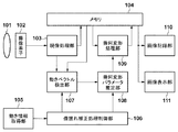
図1は、本発明の第1の実施形態における撮像装置の構成を示すブロック図である。同図において、光学系101は被写体像を形成し、CCDセンサやCMOSセンサ等から構成される撮像素子102により光学系101が形成した被写体像を光電変換する。現像処理部103は不図示のA/D変換部、オートゲイン制御部(AGC)、オートホワイトバランス部を含み、撮像素子102から出力される電気信号からデジタルの映像信号を形成する。撮像素子102及び現像処理部103により、画像の取得を行う撮像系が構成される。メモリ104は、現像処理部103により形成された、1フレームまたは複数フレーム分の画像の映像信号を一時的に記憶保持する。
<First Embodiment>
FIG. 1 is a block diagram illustrating a configuration of an imaging apparatus according to the first embodiment of the present invention. In the figure, an
動き情報取得部105は、手振れやカメラワーク等の撮像装置の動きの種類及び動き量を含む動き情報を取得するジャイロセンサ等の検出装置で構成される。像振れ補正処理制御部106は、動き情報取得部105から得られる撮像装置の動き情報に基づいて後述の動きベクトル検出部107及び幾何変形パラメータ推定部108の処理内容を変更する。動きベクトル検出部107では、現像処理部103及びメモリ104から入力される2枚のフレーム画像間の動きベクトルを検出する。
The motion
幾何変形パラメータ推定部108では、動きベクトル検出部107において検出された動きベクトルを用いて、像振れ補正処理制御部106により変更された処理を行い、フレーム画像間の像振れの動きの補正量を幾何変形パラメータとして出力する。幾何変形処理部109は、像振れ補正の為の幾何変形パラメータに基づいて、フレーム画像に対して像振れを補正するための幾何変形処理を行う。そして、画像記録部110では像振れ補正処理の施された映像を記録媒体に記録し、画像表示部111は像振れ補正処理の施された映像を不図示のディスプレイへ表示する。
The geometric deformation
以上のように構成された撮像装置の動作について、図2に示すフローチャートを用いて説明する。S201では、光学系101によって形成された被写体像を、撮像素子102が被写体輝度に応じたアナログ信号に変換して出力し、現像処理部103の処理を施すことで映像信号が生成される。ここで、現像処理部103は、不図示のA/D変換部によってアナログ信号を例えば12ビットのデジタル信号に変換し、更に、不図示のAGC及びAWBによって信号レベル補正や白レベル補正を行う。そして、現像処理部103により処理されたデジタル映像信号は、メモリ104に記憶保持される。第1の実施形態における撮像装置では、所定のフレームレートで順次フレーム画像が生成され、メモリ104に記憶保持されたフレーム画像は動きベクトル検出部107に入力される。また、メモリ104において記憶保持されているフレーム画像も順次更新される。
The operation of the imaging apparatus configured as described above will be described with reference to the flowchart shown in FIG. In step S <b> 201, the
S202では、画像入力と並行して、動き情報取得部105により撮像装置の動き情報を取得する。動き情報取得の一例としてジャイロセンサを使用した場合には、撮像装置のロール、ピッチ、そしてヨー方向の動き情報を得ることができる。なお、動き情報の取得手段はジャイロセンサに限られるものではなく、撮像装置の動き情報を得られるその他の手段を用いても良い。
In S202, in parallel with the image input, the motion
S203では、像振れ補正処理制御部106において、動き情報取得部105から得られる撮像装置の動き情報に基づいて、動きベクトル検出部107における動きベクトルの検出領域及び検出数を設定する。
In step S <b> 203, the image blur correction
表1は像振れ補正の対象とする像振れの動き成分と、その動き成分を精度良く補正する為に必要となる動きベクトルの検出領域及び検出数との関係を示す。また、図3は像振れの動き成分と検出領域の関係を表す概要図を示している。表1は、例えば像振れ補正の対象とする像振れの動き成分としてあおりの補正を行う場合には、画面全域から多数の動きベクトルを検出する必要があることを示している。 Table 1 shows the relationship between the image blur motion component to be subjected to image blur correction, and the motion vector detection area and the number of detections necessary for accurately correcting the motion component. FIG. 3 is a schematic diagram showing the relationship between the motion component of image blur and the detection area. Table 1 shows that it is necessary to detect a large number of motion vectors from the entire screen when, for example, correction of tilt is performed as a motion component of image blur that is an object of image blur correction.

図3を用いてその理由を説明する。図3の(a)はフレーム画像間で縦方向のあおりの動きが生じている場合に検出される動きベクトルの大きさと方向を模式的に表している。ここで、301はフレーム画像全体、302はあおりの動きを表す動きベクトル、そして303は動きベクトルの検出を行う領域を示している。同図より、あおりの動きでは画像301上の各位置において動きベクトルの大きさや方向が異なる。そのため、画面全域から動きベクトルを検出しなければ、あおりの動きを精度良く推定することはできない。また、あおりのような複雑な動きに対しては多数の動きベクトルを用いなければ安定した推定を行うことができない。従って、あおりの動きまで像振れ補正の対象とする場合には303に示すようにフレーム画像の全域から多数の動きベクトルを検出する必要がある。
The reason will be described with reference to FIG. FIG. 3A schematically shows the magnitude and direction of a motion vector that is detected when vertical tilt motion occurs between frame images. Here,
また、回転の動き成分を像振れ補正の対象とする場合には、画面の中央近辺の領域から動きベクトルを検出すれば良い。ここで、画像上に生じる回転の動きベクトルは、図3(b)のベクトル304が示すように画像中心を回転中心とした点対称の動きを示す。従って、回転の動きの推定には画像中心を基準として点対称の位置関係にある動きベクトル対を検出すれば良く、必ずしも画面全域から動きベクトルを検出する必要は無い。つまり、画像中心を含み、垂直方向が狭くなっている領域305を動きベクトルの検出領域としても、回転の動きを検出するのに必要な動きベクトルを検出することできる。このとき、画像は上から下へ向かってラスタ的に入力されるため、検出領域305を画像の上部や中央部の近傍に配置することで画像全域の入力が完了するよりも早い時点で動きベクトルの検出を完了することができる。ただし、回転の動き成分を精度良く推定するためには、回転中心及び回転中心を基準として点対称の位置関係にある動きベクトル対が検出できるような配置にする必要がある。
In addition, when a rotational motion component is a target for image blur correction, a motion vector may be detected from an area near the center of the screen. Here, the rotational motion vector generated on the image indicates a point-symmetrical motion with the center of the image as the rotational center, as indicated by the
また、あおりの検出領域303と比較して検出領域が狭くなる分だけ、検出する動きベクトルの数を少なくすることができる。以上のことから、あおりの動きが像振れ補正の対象に含まれていなければ、回転の動きを像振れ補正対象とした場合に、あおりの動きが像振れ補正の対象に含まれている場合よりも処理時間を短く、演算量を少なくすることができる。
In addition, the number of motion vectors to be detected can be reduced by the amount that the detection area is narrower than the
また、図3(c)における動きベクトル群306に示されるような並進の動きを像振れ補正の対象とする場合には、画像上のごく一部の領域307について動きベクトルの検出を行えば良い。撮像装置の支配的な動きが並進の動きである場合には、そこから検出される動きベクトル306は画像上のどの位置においても同じ大きさと方向を有している。従って、動きベクトルを検出する位置に制限は無く、回転の動きよりもさらに少ない数の動きベクトルからでも精度良く並進の動きを推定することが可能となる。また、回転の動きの場合とは異なり、点対称の位置関係で動きベクトルを検出する必要も無いため、検出領域を画像のより上部に配置することが可能となる。これにより、あおり及び回転の動きが像振れ補正の対象に含まれていなければ、並進の動きを推定する場合に、更なる演算量の削減と処理時間の短縮を図ることが可能となる。
In addition, when translational motion as shown in the
このように、補正の対象とする像振れの動き成分に応じて動きベクトルの検出領域及び検出数を変更することで演算量を削減し、処理時間を短縮し、消費電力を少なくすることが可能となる。 In this way, it is possible to reduce the amount of calculation by reducing the motion vector detection area and the number of detections according to the image blur motion component to be corrected, shorten the processing time, and reduce the power consumption. It becomes.
ここで、表1においてより上段に示されている像振れの動き成分に対する動きベクトルの検出領域及び検出数は、より下段に示されている像振れの動き成分のもの包含している。例えば、あおりの動きを対象とした動きベクトルの検出領域と検出数を選択した場合には、同時に回転及び並進の幾何変形成分を推定するための動きベクトルを検出することが可能である。本第1の実施形態では、あおり、回転、並進の動きについて述べたがこれに限るものではなく、例えば変倍やせん断の動きについても同様の考えに基づいて動きベクトルの検出領域と検出数を変更することで、演算量の削減を図ることが可能となる。このようにしてS203で変更された動きベクトル検出領域及び検出数の情報は動きベクトル検出部107へ伝送される。
Here, the motion vector detection region and the number of detections for the image blur motion component shown in the upper part of Table 1 include those of the image blur motion component shown in the lower part. For example, when a motion vector detection region and the number of detections for the tilt motion are selected, it is possible to detect a motion vector for estimating rotational and translational geometric deformation components at the same time. In the first embodiment, the movement of tilt, rotation and translation has been described. However, the present invention is not limited to this. For example, the motion vector detection region and the number of detections are also based on the same idea for zooming and shearing movements. By changing, it becomes possible to reduce the amount of calculation. The information on the motion vector detection region and the number of detections changed in S203 in this way is transmitted to the motion
S204では、動きベクトル検出部107において、像振れ補正処理制御部106で決定された動きベクトル検出領域及び検出数に基づいて、入力された2枚のフレーム画像間での動きベクトルの検出を行う。第1の実施形態では、動きベクトル検出方法の一例としてテンプレートマッチングを用いた方法について説明する。
In S204, the motion
ここで、図4を参照してテンプレートマッチングの概要について説明する。図4(a)は原画像、図4(b)は参照画像であり、これらの画像は現像処理部103及びメモリ104から入力されるフレーム画像である。そして、図4の401に示すように原画像中の任意の位置にテンプレートブロックを配置し、テンプレートブロック401と参照画像の各領域との相関値を算出する。このとき、参照画像の全領域に対して相関値を算出するのでは演算量が膨大なものとなるため、実際には参照画像上の相関値を算出する矩形領域をサーチ範囲402として設定する。サーチ範囲402の位置や大きさについては特に制限は無いが、サーチ範囲402の内部にテンプレートブロック401の移動先に相当する領域が含まれていないと正しい動きベクトルを検出することはできない。
Here, an outline of template matching will be described with reference to FIG. 4A is an original image, and FIG. 4B is a reference image. These images are frame images input from the
本第1の実施形態では、相関値の算出方法の一例として差分絶対値和(Sum of Absolute Difference、以下「SAD」と略す。)を使用する。SADの計算式を式(1)に示す。 In the first embodiment, a sum of absolute difference (hereinafter abbreviated as “SAD”) is used as an example of a correlation value calculation method. The calculation formula of SAD is shown in Formula (1).
本第1の実施形態では、相関値の一例としてSADを使用しているが、これに限るものではなく、差分二乗和(SSD)や正規化相互相関(NCC)等の他の相関値を用いても良い。そして、サーチ範囲402の全領域について相関値算出領域403を移動させて相関値を算出する。テンプレートブロック401とサーチ範囲402との間で相関値を算出し、相関が最も高くなる位置を判定することにより、原画像上のテンプレートブロックが参照画像においてどの位置に移動したか、つまり画像間の動きベクトルを検出することが可能となる。以上のような動きベクトル検出処理を入力されたフレーム画像間の複数の領域で行う。そして、検出された動きベクトル群は幾何変形パラメータ推定部108に伝送される。
In the first embodiment, SAD is used as an example of the correlation value. However, the present invention is not limited to this, and other correlation values such as sum of squares of differences (SSD) and normalized cross correlation (NCC) are used. May be. Then, the correlation
また、S205では、像振れ補正処理制御部106において、像振れ補正の対象とする像振れの動き成分に応じて幾何変形パラメータの推定方法を選択する。本第1の実施形態では、幾何変形を表す手段の一例としてホモグラフィ行列と呼ばれる3×3の行列式を用いる場合について説明する。
In step S <b> 205, the image shake correction
まず、画像上のある点a、
a = [x, y, 1]T …(2)
が次フレームにおいて点a′、
a' = [x', y', 1]T …(3)
に移動したとする。ここで、添え字Tは転置行列であること示す。
First, a certain point a on the image,
a = [x, y, 1] T (2)
Is the point a ′ in the next frame,
a '= [x', y ', 1] T ... (3)
Suppose you move to. Here, the subscript T indicates a transposed matrix.
式(2)の点aと式(3)の点a′の対応関係は、ホモグラフィ行列Hを用いることにより、
a' = Ha …(4)
と表すことができる。
The correspondence between the point a in the equation (2) and the point a ′ in the equation (3) is obtained by using the homography matrix H:
a '= Ha (4)
It can be expressed as.
ホモグラフィ行列Hは画像間の並進、回転、変倍、せん断、あおりによる変形量を示す行列式であり、以下の式(5)により表すことができる。
ホモグラフィ行列Hの各要素は、ステップS204で得られる動きベクトル群、つまりフレーム画像間における代表点の対応関係を用いて推定処理を行うことにより求めることができる。 Each element of the homography matrix H can be obtained by performing an estimation process using the motion vector group obtained in step S204, that is, the correspondence of representative points between frame images.
表1には、上述した動きベクトルの検出領域及び検出数の他に、像振れ補正対象とする像振れの動き成分に対する幾何変形パラメータの推定方法が示されている。表1より、あおりの動きまでを像振れ補正の対象とした場合には8自由度の最小二乗法を使用して、幾何変形パラメータを推定する必要がある。ここで、式(5)のホモグラフィ行列Hでは、パラメータh13、h23が並進の動き成分、h11、h12、h21、h22が回転、変倍、せん断の動き成分を表し、そしてh31、h32があおりの動き成分を表している。従って、あおりの動き成分までを像振れ補正の対象とする場合には上記の8個のパラメータ全てを推定しなければならないため、8自由度の最小二乗法を使用する必要がある。 Table 1 shows a method of estimating a geometric deformation parameter with respect to a motion component of an image blur to be corrected for image blur, in addition to the above-described motion vector detection region and the number of detections. From Table 1, when up to the tilt movement is the target of image blur correction, it is necessary to estimate the geometric deformation parameter using the least square method with 8 degrees of freedom. Here, in the homography matrix H of Equation (5), the parameters h 13 and h 23 represent translational motion components, and h 11 , h 12 , h 21 and h 22 represent rotational, scaling and shearing motion components, H 31 and h 32 represent the movement components of the cage. Accordingly, in the case where even the motion component of the tilt is the target of image blur correction, since all the above eight parameters must be estimated, it is necessary to use the least square method with 8 degrees of freedom.
次に、回転の動き成分までを像振れ補正の対象とする場合には、あおりの動き成分を表すパラメータであるh31及びh32を推定する必要が無いため、それ以外の6個のパラメータ推定、つまり6自由度での最小二乗法による推定を行えば良いことになる。従って、補正する像振れの動き成分を回転の動き成分まで(並進成分と回転成分)とした場合には、あおりまで(並進成分、回転成分、およびあおり成分)の場合と比較して自由度が少ない分、ベクトル数が少なくても安定した解を得ることが可能である。この場合、さらに演算量を削減することができる。 Next, in the case of subjecting the rotational motion component to image blur correction, there is no need to estimate the parameters h 31 and h 32 representing the tilt motion component, so the other six parameter estimations are performed. In other words, estimation by the least square method with six degrees of freedom may be performed. Therefore, if the motion component of the image blur to be corrected is up to the rotational motion component (translational component and rotational component), the degree of freedom is higher than that in the case of up to the tilt (translational component, rotational component, and tilt component). Therefore, a stable solution can be obtained even if the number of vectors is small. In this case, the calculation amount can be further reduced.
そして、並進の動き成分のみを像振れ補正の対象とする場合には、式(5)におけるh13及びh23のパラメータについてのみ推定を行えば良い。また、並進の動き成分は画像の平行移動という簡単な動きであるため、最小二乗法のような統計的な推定方法を使用する必要はなく、ヒストグラム処理のような単純な処理でも精度良く推定を行うことが可能となる。さらに、画像上に生じているのが並進の動きのみであれば、画像上のどの位置においても同じ大きさ、同じ方向の動きとなるため、少ない数の動きベクトルでも精度良く並進の動きを推定することが可能である。以上のように並進の幾何変形量の推定では少ない動きベクトルによる単純な推定方法でパラメータの推定が可能であるため、演算量を大幅に削減することができる。 When only the translational motion component is to be subjected to image blur correction, only the parameters h 13 and h 23 in equation (5) may be estimated. In addition, since the translational motion component is a simple motion called parallel translation of the image, there is no need to use a statistical estimation method such as the least square method, and the estimation can be performed with a simple process such as histogram processing with high accuracy. Can be done. In addition, if only translational motion is occurring on the image, the motion will be the same in the same direction and in the same direction at any position on the image, so the translational motion can be accurately estimated with a small number of motion vectors. Is possible. As described above, since the estimation of the translational geometric deformation amount enables parameter estimation by a simple estimation method using a small number of motion vectors, the calculation amount can be greatly reduced.
なお、上記例では、幾何変形量の推定方法として最小二乗法やヒストグラム処理を用いているが、これに限られるものではなく他の推定手法を用いても良い。 In the above example, the least square method or the histogram process is used as the geometric deformation amount estimation method, but the present invention is not limited to this, and other estimation methods may be used.
また、S205では像振れ補正対象とする像振れの動き成分に応じて推定方法を変更することで演算量の削減を図っているが、総合的な演算量はS203で決定した動きベクトルの検出領域及び検出数との組み合わせで決定される。表1より、あおりの動き成分に対しては画面全体から多くの動きベクトルを検出し、統計的な処理で式(5)に示した8個全ての幾何変形パラメータを求める必要があるため演算量は増大する。それに対して、例えば並進の幾何変形に対しては画面の一部の領域から小数の動きベクトルを検出すれば良く、さらに推定方法もヒストグラム処理のような単純なもので良いため、演算量を大幅に削減することが可能である。そして、選択された幾何変形量推定方法の情報は幾何変形パラメータ推定部108へ伝送される。
In S205, the amount of calculation is reduced by changing the estimation method in accordance with the image blur motion component to be subjected to image blur correction, but the total amount of calculation is the motion vector detection region determined in S203. And a combination with the number of detections. From Table 1, it is necessary to detect a large number of motion vectors from the entire screen and to calculate all eight geometric deformation parameters shown in Equation (5) by statistical processing for the tilt motion component. Will increase. On the other hand, for example, for translational geometric deformation, it is only necessary to detect a small number of motion vectors from a partial area of the screen, and the estimation method can be as simple as histogram processing. Can be reduced. Information on the selected geometric deformation amount estimation method is transmitted to the geometric deformation
S206では、動きベクトル検出部107から得られた動きベクトル群を用いて、像振れ補正処理制御部106で選択された幾何変形量推定方法に基づいてフレーム画像間の幾何変形量の推定を行い、像振れの補正量を算出する。ここで、S205で述べたような方法で推定されたホモグラフィ行列Hは、撮像装置の像振れによる画像の変形量を表す。このため、画像の像振れを補正するには、像振れによる変形を打ち消すような画像変形量となるようにホモグラフィ行列Hを変換する必要がある。つまり、ホモグラフィ行列Hを逆行列Hに変換することにより、点a′と点aの対応関係は、
a = H-1a' …(6)
と表すことができる。式(6)により、像振れが生じた後の点a’を、像振れが生じる前の点aと同じ座標に戻すことが可能となる。
In S206, the amount of geometric deformation between the frame images is estimated based on the geometric deformation amount estimation method selected by the image blur correction
a = H -1 a '(6)
It can be expressed as. Expression (6) makes it possible to return the point a ′ after image blurring to the same coordinates as the point a before image blurring.
S207では、幾何変形処理部109において、S206で得られた像振れ補正の為の幾何変形量を用いて画像に幾何変換処理を施すことで像振れ補正を行う。そして、S208では像振れ補正処理が施された映像を、画像記録部110によって不図示の記憶装置に記憶したり、画像表示部111において不図示の表示装置に表示したりする。
In step S207, the geometric
ここまで、像振れ補正対象とする像振れの動き成分に応じて動きベクトルの算出方法及び画像変形量の推定方法を切り替えることにより演算量を削減することについて述べた。ここで、実際にどの像振れの動き成分を補正するべきかについて、動き情報取得部105より得られるジャイロセンサで計測された撮像装置の動き情報を利用して判定する方法について説明する。
Up to this point, it has been described that the amount of calculation is reduced by switching between the motion vector calculation method and the image deformation amount estimation method in accordance with the image blur motion component to be subjected to image blur correction. Here, a method for determining which image shake motion component should actually be corrected using the motion information of the imaging device measured by the gyro sensor obtained from the motion
表2に、動き情報取得部105のジャイロセンサから得られる撮像装置の動き情報と、それに対する像振れの動き成分の組み合わせを示す。ジャイロセンサからは撮像装置のパン・チルト及びロールの動き量の大きさを取得することが可能である。即ち、光軸に直交する2軸回りの撮像装置の回転と、光軸回りの撮像装置の回転の動き量の大きさを得られる。このとき、撮像装置のパン・チルトの動きが画像上でのあおりの変形を表し、撮像装置のロールの動きが画像上での回転の動き(画像の傾き)を示している。
Table 2 shows a combination of the motion information of the imaging device obtained from the gyro sensor of the motion
従って、例えばパン・チルトの動き量が予め定められた閾値よりも小さく、さらにロールの動き量も予め定められた閾値よりも小さい場合には画像上に現れている像振れの動き成分としてはあおりと回転の成分は小さく、並進の成分が支配的であると判定できる。この場合には、並進の動き成分のみを像振れ補正対象とすれば良いので、表1に示すように、画像の一部の領域から少数の動きベクトルを検出し、ヒストグラム処理により並進の動きを推定すれば良い。また、パン・チルトの動き量は閾値より小さいが、ロールの動き量が閾値以上の場合には、画像上に現れている像振れの動き成分としてはあおりの成分は小さく、回転の成分が大きいと判定できる。この場合には、回転の像振れの動き成分まで(並進成分と回転成分)を像振れ補正対象とする必要がある。そのため、表1に示すように、画面中央付近の領域から動きベクトルを検出し、6自由度の最小二乗法を用いて式(5)に示したホモグラフィ行列の回転の動きを表すパラメータまでの推定を行う。さらに、ロールの動き量の大きさに関わらず、パンニングやチルティングの動き量が閾値以上の場合には画像上に現れている像振れの動き成分としてあおりの成分が顕著になっていると判定できる。このような場合には、表1に示すように、画面全域から多数の動きベクトルを検出し、それらを用いて8自由度の最小二乗法により、式(5)に示したホモグラフィ行列のあおりの動きを表すパラメータまでの推定を行う。 Therefore, for example, when the amount of pan / tilt movement is smaller than a predetermined threshold and the amount of movement of the roll is also smaller than a predetermined threshold, the movement component of the image blur appearing on the image is an increase. It can be determined that the rotation component is small and the translation component is dominant. In this case, since only the translational motion component needs to be subject to image blur correction, as shown in Table 1, a small number of motion vectors are detected from a partial region of the image, and the translational motion is detected by histogram processing. You can estimate. Also, the pan / tilt motion amount is smaller than the threshold value, but when the roll motion amount is greater than or equal to the threshold value, the movement component of the image blur appearing on the image is small and the rotation component is large. Can be determined. In this case, it is necessary to set the image blur correction target up to the rotational image blur motion component (translation component and rotation component). Therefore, as shown in Table 1, a motion vector is detected from the area near the center of the screen, and the parameters representing the rotation motion of the homography matrix shown in Equation (5) using the least square method with 6 degrees of freedom are used. Make an estimate. Furthermore, regardless of the amount of roll motion, if the amount of panning or tilting is greater than or equal to a threshold, it is determined that the tilt component is prominent as a motion component of image blurring that appears on the image. it can. In such a case, as shown in Table 1, a large number of motion vectors are detected from the entire screen, and the homography matrix shown in Equation (5) is tilted by using the least square method with 8 degrees of freedom. Up to a parameter representing the motion of the.
以上説明したように、像振れ補正処理制御部106は、動き情報取得部105から得られる撮像装置の動き情報を用いて画像上に現れる像振れの動き成分を判定する。そして、判定結果に応じて、良好な像振れ補正を行うために十分な動きベクトルの検出領域及び検出数、そして幾何変形パラメータ推定方法を選択する。これにより、撮像装置に生じている像振れの状況に応じて像振れ補正処理に要する演算量を削減することができるため、消費電力を抑えることが可能となる。
As described above, the image shake correction
しかしながら、撮影中に像振れ補正方法を単純に切り替えるだけでは、切り替わりの前後のフレーム画像間で幾何変形のモデルが変わることにより、動きに不連続さが生じてしまう可能性がある。これを解消する方法の一例としては、幾何変形パラメータに時間的な平滑化処理を施すというものがある。これは、像振れ補正処理をしている間は過去の数フレーム分の幾何変形パラメータを記憶保持しておき、切り替わった直後の数フレームに対して過去の幾何変形パラメータの影響を残した幾何変形パラメータに補正して像振れ補正処理を行うというものである。これにより、切り替わりの瞬間の不連続な動きを解消し、徐々に異なる推定方法による像振れ補正結果に切り替えていくことが可能となる。ここで、平滑化の方法には特に制限は無く、例えば移動平均や、IIRフィルタ等、どのような方法を用いても良い。また、以上の処理は幾何変形パラメータ推定部108において行われる。
However, simply switching the image blur correction method during shooting may cause discontinuity in motion due to a change in the geometric deformation model between frame images before and after the switching. As an example of a method for solving this, there is a method of performing temporal smoothing processing on the geometric deformation parameter. This is because geometric deformation parameters for the past several frames are stored and retained during image blur correction processing, and the geometric deformation parameters that leave the influence of the past geometric deformation parameters on the few frames immediately after switching are stored. Image blur correction processing is performed by correcting the parameters. As a result, it is possible to eliminate the discontinuous movement at the moment of switching and gradually switch to the image blur correction result by different estimation methods. Here, the smoothing method is not particularly limited, and any method such as a moving average or an IIR filter may be used. The above processing is performed in the geometric deformation
なお、上記説明では、撮像装置の動きが、あおり、回転、並進のいずれかであるかに応じて、動きベクトルの検出領域及び検出数、及び幾何変形量の推定方法を変更した。しかしながら、本発明はこれに限るものではなく、撮像装置の動きがあおりか否か、回転か否か、並進か否かのいずれかを判断し、判断結果に応じて動きベクトルの検出領域及び検出数、及び幾何変形量の推定方法を変更しても良い。例えば、並進か否かを判断する場合、並進であれば表1に示すように検出領域を画面上部、検出数を少、幾何変形量の推定方法をヒストグラムとし、並進でなければ、検出領域を画面全域、検出数を多、幾何変形量の推定方法を8自由度の最小二乗法とする。このように制御することで、常に画面全体を検出領域とし、検出数を多、幾何変形量の推定方法を8自由度の最小二乗法とする場合と比較して、並進時の像振れ補正処理に要する演算量を削減することができる。 In the above description, the motion vector detection area, the number of detections, and the estimation method of the geometric deformation amount are changed according to whether the motion of the imaging apparatus is tilt, rotation, or translation. However, the present invention is not limited to this, and it is determined whether the imaging apparatus is moving, rotating, or translating, and the motion vector detection region and detection are determined according to the determination result. The estimation method of the number and the geometric deformation amount may be changed. For example, when determining whether or not to translate, if translation, the detection area is the upper part of the screen as shown in Table 1, the number of detection is small, the estimation method of the geometric deformation is a histogram, and if not translation, the detection area is The entire screen, the number of detections are large, and the method of estimating the geometric deformation is a least square method with 8 degrees of freedom. By controlling in this way, image blur correction processing during translation is always performed as compared with the case where the entire screen is always set as the detection region, the number of detections is large, and the geometric deformation amount estimation method is the least square method with 8 degrees of freedom. Can reduce the amount of computation required.
以上説明したように、本第1の実施形態によれば、撮像装置の動きに応じて動きベクトルの検出領域及び検出数、及び画像幾何変形量の推定方法を変更することで、像振れ補正処理に要する演算量を削減することができる。これにより、撮像装置の動きに応じた効率的な像振れ補正処理を行うことが可能となり、消費電力を削減することが可能となる。 As described above, according to the first embodiment, the image blur correction process is performed by changing the detection area and the number of motion vectors and the estimation method of the image geometric deformation amount according to the motion of the imaging apparatus. Can reduce the amount of computation required. Accordingly, it is possible to perform an efficient image blur correction process according to the movement of the imaging device, and it is possible to reduce power consumption.
<第2の実施形態>
次に、本発明の第2の実施形態について説明する。図5は、第2の実施形態における撮像装置の構成を示すブロック図である。本第2の実施形態では、入力画像上に存在する特定の領域を避けて動きベクトル検出領域を設定することで、より良好な像振れ補正映像を生成する。なお、図5に示す本第2の実施形態の撮像装置は、図1に示した構成に加えて、領域判定部501を更に有する。それ以外は図1に示した構成要素と同じであるので、図1と同符号を付して説明を省略する。
<Second Embodiment>
Next, a second embodiment of the present invention will be described. FIG. 5 is a block diagram illustrating a configuration of the imaging apparatus according to the second embodiment. In the second embodiment, a better image blur correction image is generated by setting a motion vector detection region while avoiding a specific region existing on the input image. Note that the imaging apparatus according to the second embodiment illustrated in FIG. 5 further includes an
また、本第2の実施形態における撮像装置の動作のフローチャートを図6に示す。本第2の実施形態では、第1の実施形態と異なる処理を行う部分についてのみ詳細に説明する。 Further, FIG. 6 shows a flowchart of the operation of the imaging apparatus in the second embodiment. In the second embodiment, only a portion that performs processing different from that of the first embodiment will be described in detail.
S201及びS202で行われる処理は、図2におけるS201及びS202で行われる処理と同じである。S601では、領域判定部501において、S201で入力された画像中に存在する像振れの動きを検出することが困難な、予め決められた条件を満たす除外領域を特定する。ここで、像振れの動きを検出することが困難な領域とは、次のような領域のことを指す。まず、画像中に移動物体が存在している領域である。移動物体から検出される動きベクトルは移動物体の動きを表すものであり、これらの動きを用いても像振れの動きを表す幾何変形パラメータを推定することはできない。また、低コントラスト領域では、その領域についてはテクスチャが存在しないためテンプレートマッチングでは動きベクトルを正しく検出することはできない。更に、繰り返し領域では、同じテクスチャが複数存在するためにどれが正しい動きベクトルであるかを判定することは困難である。
The processing performed in S201 and S202 is the same as the processing performed in S201 and S202 in FIG. In step S601, the
そこで、本ステップでは上記のような像振れを表す動きベクトルを正しく検出することが困難な領域を検出し、以降の処理における動きベクトル検出領域の設定時にこれらの領域を避けて検出領域の設定を行うように指示する。 Therefore, in this step, the areas where it is difficult to detect the motion vector representing the image blur as described above are detected, and when setting the motion vector detection area in the subsequent processing, avoid these areas and set the detection area. Instruct to do.
ここで、移動物体の検出方法としては、例えば背景差分法を利用したり、ジャイロセンサから得られる撮像装置の動き情報を利用する方法等がある。また、低コントラスト領域の判定方法としては、例えば画像中の各領域について分散値を算出してその領域のテクスチャの複雑さを判定すれば良い。さらに、繰り返し領域の判定方法については、例えば画像の各領域について輝度勾配のような特徴量を算出し、周辺領域の特徴量との比較を行うことで同じようなテクスチャが存在しているかどうかを判定することができる。それ以外にも、例えば歩行中の人物のような領域を移動物体として抽出する場合には、一般的な顔認識の手法を使用して人物の位置や大きさを抽出するといった方法がある。 Here, as a method for detecting a moving object, for example, there are a method using a background difference method, a method using motion information of an imaging device obtained from a gyro sensor, and the like. As a method for determining a low contrast region, for example, a variance value may be calculated for each region in the image to determine the texture complexity of the region. Further, regarding the determination method of the repetitive region, for example, a feature amount such as a luminance gradient is calculated for each region of the image, and it is determined whether or not a similar texture exists by comparing with a feature amount of the peripheral region. Can be determined. In addition, for example, when a region such as a walking person is extracted as a moving object, there is a method of extracting the position and size of the person using a general face recognition method.
そして、S602では、像振れ補正処理制御部106において、動き情報取得部から得られる撮像装置の動き情報に加えて、領域判定部501から得られる移動物体領域情報を用いて動きベクトルの検出領域を設定する。
In step S <b> 602, the image blur correction
ここでは、像振れを表す動きベクトルが検出困難な領域の例として、画像中に移動物体が存在している場合について説明する。図7に、入力画像中に移動物体が存在している場合の概要図を示す。同図において、701は移動物体を示しており、702が移動物体701から検出される動きベクトルを示している。それに対して703は、撮像装置が縦方向に動いた場合に生じる像振れの動きを表す動きベクトルを示している。像振れの動きは撮像装置の動きに起因するものであり、静止している領域の動きベクトルから得ることができるため、多くの場合において動きベクトル703に示すような背景領域の動きが像振れの動きを表していることになる。また、像振れの動きを表す動きベクトル703は画像中に並進の像振れが生じていることを示している。このような場合には、並進の像振れのみを像振れ補正対象となる動き成分とすればよいので、表1より、動きベクトルの検出領域は画像上のどこか一部の領域に設定すればよいことになる。
Here, a case where a moving object is present in an image will be described as an example of a region in which a motion vector representing image blur is difficult to detect. FIG. 7 shows a schematic diagram when a moving object is present in the input image. In the figure,
しかしながら、例えば動きベクトルの検出領域を図7の704に示すような位置に設定してしまうと、移動物体の動きベクトルが検出されることになるため、像振れの動き成分を表す動きベクトルを検出することはできない。そこで、領域判定部501から得られる移動物体領域の判定情報を用いることで、705に示すような、移動物体の存在していない領域、つまり背景領域に動きベクトルの検出領域を設定する。これにより、画像上に移動物体が存在している場合でも、正しく像振れの動きを表す動きベクトルを検出することが可能となる。また、例えば画像上の多くの領域が移動物体の存在する領域であった場合には動きベクトル検出領域の位置だけでなく大きさも変更することにより、正しい動きベクトルのみを検出することができる。
However, for example, if the motion vector detection area is set to a position as indicated by
本第2の実施形態においては、並進の像振れを像振れ補正の対象とする場合について述べたが、回転やあおりの動きについても同様の方法により動きベクトル検出領域を設定すれば良好な像振れ補正結果を得ることが可能である。 In the second embodiment, the case where the translational image blur is the target of the image blur correction has been described. However, if the motion vector detection region is set by the same method for the rotation and the movement of the tilt, a good image blur is achieved. It is possible to obtain a correction result.
なお、図6におけるS204からS208における処理は、第1の実施形態で説明した図2におけるS204からS208における処理と同様であるため、説明を省略する。 Note that the processing from S204 to S208 in FIG. 6 is the same as the processing from S204 to S208 in FIG. 2 described in the first embodiment, and thus description thereof is omitted.
上記の通り本第2の実施形態によれば、第1の実施形態と同様に撮像装置の動き情報に基づいて動きベクトルの検出領域や幾何変形パラメータの推定を行うことに加えて、像振れ補正に必要な動きベクトルを正しく求めることが困難な領域の判定を行う。そして、判定された領域を避けるように、動きベクトルを検出する領域の位置や大きさを設定する。これにより、第1の実施形態と同様の効果に加えて、どのようなシーンに対しても良好に像振れ補正処理を行うことができる。 As described above, according to the second embodiment, in addition to the estimation of the motion vector detection area and the geometric deformation parameter based on the motion information of the imaging apparatus, as in the first embodiment, image blur correction is performed. A region where it is difficult to correctly obtain a motion vector necessary for the determination is determined. Then, the position and size of the area where the motion vector is detected are set so as to avoid the determined area. Accordingly, in addition to the same effects as those of the first embodiment, it is possible to perform the image blur correction process satisfactorily for any scene.
Claims (11)
被写体像を撮像して画像を出力する撮像手段と、
前記撮像装置の動き情報を取得する動き情報取得手段と、
前記撮像手段により撮像された画像の検出領域から動きベクトルを検出するベクトル検出手段と、
前記動き情報取得手段により取得した動き情報に応じて、前記検出領域及び前記画像の像振れを補正するための像振れ補正方法を決定する制御手段と、
前記ベクトル検出手段により検出された動きベクトルに基づいて、前記制御手段により決定された像振れ補正方法を用いて前記画像の像振れを補正する像振れ補正手段と
を有することを特徴とする撮像装置。 An imaging device that performs image blur correction processing,
Imaging means for capturing a subject image and outputting the image;
Motion information acquisition means for acquiring motion information of the imaging device;
Vector detection means for detecting a motion vector from a detection region of an image captured by the imaging means;
Control means for determining an image blur correction method for correcting the image blur of the detection area and the image according to the motion information acquired by the motion information acquisition means;
An image blur correction unit that corrects image blur of the image using an image blur correction method determined by the control unit based on a motion vector detected by the vector detection unit; .
前記制御手段は、前記撮像装置の光軸に直交する軸回り方向の回転の動き量と光軸回り方向の回転の動き量の大きさに応じて、前記撮像装置の動きを決定することを特徴とする請求項2乃至6のいずれか1項に記載の撮像装置。 The motion information acquisition means acquires, as the motion information of the imaging device, a rotational amount of rotation around the axis orthogonal to the optical axis of the imaging device and a rotational amount of rotation around the optical axis,
The control means determines the movement of the imaging device according to the amount of rotational movement around the axis orthogonal to the optical axis of the imaging device and the amount of rotational movement around the optical axis. The imaging device according to any one of claims 2 to 6.
前記制御手段は、
前記撮像装置の光軸に直交する軸回り方向の回転の動き量が閾値よりも小さく、前記光軸回り方向の回転の動き量が閾値よりも小さい場合に、前記撮像装置の動きが並進と判断し、
前記撮像装置の光軸回り方向の回転の動き量が閾値よりも小さく、前記撮像装置の光軸に直交する軸回り方向の回転の動き量が閾値以上の場合に、前記撮像装置の動きが回転と判断し、
前記撮像装置の光軸に直交する軸回り方向の回転の動き量が閾値以上である場合に、前記撮像装置の光軸回り方向の回転の動き量に関わらず、前記撮像装置の動きをあおりと判断する
ことを特徴とする請求項4乃至6のいずれか1項に記載の撮像装置。 The motion information acquisition means acquires, as motion information of the imaging device, a motion amount in the direction around the axis orthogonal to the optical axis of the image pickup device and a motion amount of rotation in the direction around the optical axis,
The control means includes
When the amount of rotational movement around the axis orthogonal to the optical axis of the imaging device is smaller than a threshold and the amount of rotational movement around the optical axis is smaller than the threshold, the motion of the imaging device is determined to be translational. And
The movement of the imaging device rotates when the amount of rotational movement around the optical axis of the imaging device is smaller than a threshold and the amount of rotational movement around the axis orthogonal to the optical axis of the imaging device is greater than or equal to the threshold. Judging
When the amount of rotational movement around the axis orthogonal to the optical axis of the imaging device is greater than or equal to a threshold value, the movement of the imaging device is controlled regardless of the amount of rotational movement around the optical axis of the imaging device. The image pickup apparatus according to claim 4, wherein the image pickup apparatus is determined.
前記制御手段は、前記除外領域を前記検出領域に含めないことを特徴とする請求項1乃至8のいずれか1項に記載の撮像装置。 In the image picked up by the image pickup means, it further comprises area determination means for detecting an excluded area that satisfies a predetermined condition, which is difficult to detect a motion vector representing a shake of the image pickup apparatus,
The imaging apparatus according to claim 1, wherein the control unit does not include the exclusion area in the detection area.
撮像手段が、被写体像を撮像して画像を出力する撮像工程と、
動き情報取得手段が、前記撮像装置の動き情報を取得する動き情報取得工程と、
制御手段が、前記動き情報取得工程で取得した動き情報に応じて、動きベクトルを検出する前記画像における検出領域を決定する決定工程と、
ベクトル検出手段が、前記撮像工程で撮像された画像の前記検出領域から、動きベクトルを検出するベクトル検出工程と、
前記制御手段が、前記画像の像振れを補正するための像振れ補正方法を決定する制御工程と、
像振れ補正手段が、前記ベクトル検出工程で検出された動きベクトルに基づいて、前記制御工程で決定された像振れ補正方法を用いて前記画像の像振れを補正する像振れ補正手段と
を有することを特徴とする像振れ補正処理方法。 An image shake correction processing method in an imaging apparatus,
An imaging step in which an imaging unit images a subject image and outputs the image;
A motion information acquisition step in which the motion information acquisition means acquires the motion information of the imaging device;
A determining step for determining a detection region in the image for detecting a motion vector according to the motion information acquired in the motion information acquiring step;
A vector detection step in which a vector detection unit detects a motion vector from the detection region of the image captured in the imaging step;
A control step in which the control means determines an image blur correction method for correcting image blur of the image;
The image blur correction unit includes an image blur correction unit that corrects the image blur of the image using the image blur correction method determined in the control step based on the motion vector detected in the vector detection step. An image blur correction processing method characterized by the above.
Priority Applications (1)
| Application Number | Priority Date | Filing Date | Title |
|---|---|---|---|
| JP2013144854A JP6178646B2 (en) | 2013-07-10 | 2013-07-10 | Imaging apparatus and image shake correction processing method |
Applications Claiming Priority (1)
| Application Number | Priority Date | Filing Date | Title |
|---|---|---|---|
| JP2013144854A JP6178646B2 (en) | 2013-07-10 | 2013-07-10 | Imaging apparatus and image shake correction processing method |
Publications (3)
| Publication Number | Publication Date |
|---|---|
| JP2015019231A true JP2015019231A (en) | 2015-01-29 |
| JP2015019231A5 JP2015019231A5 (en) | 2016-08-25 |
| JP6178646B2 JP6178646B2 (en) | 2017-08-09 |
Family
ID=52439848
Family Applications (1)
| Application Number | Title | Priority Date | Filing Date |
|---|---|---|---|
| JP2013144854A Expired - Fee Related JP6178646B2 (en) | 2013-07-10 | 2013-07-10 | Imaging apparatus and image shake correction processing method |
Country Status (1)
| Country | Link |
|---|---|
| JP (1) | JP6178646B2 (en) |
Cited By (4)
| Publication number | Priority date | Publication date | Assignee | Title |
|---|---|---|---|---|
| JP2016201637A (en) * | 2015-04-08 | 2016-12-01 | キヤノン株式会社 | Image processing apparatus and image processing method |
| JP2017098884A (en) * | 2015-11-27 | 2017-06-01 | カシオ計算機株式会社 | Movement detection device, movement detection method, and program |
| US9674441B2 (en) | 2014-08-05 | 2017-06-06 | Canon Kabushiki Kaisha | Image processing apparatus, image processing method, and storage medium |
| US10560631B2 (en) | 2017-03-24 | 2020-02-11 | Casio Computer Co., Ltd. | Motion vector acquiring device, motion vector acquiring method, and storage medium |
Citations (2)
| Publication number | Priority date | Publication date | Assignee | Title |
|---|---|---|---|---|
| JP2000092499A (en) * | 1998-09-08 | 2000-03-31 | Canon Inc | Image coding controller, image coding control method and storage medium thereof |
| JP2007166269A (en) * | 2005-12-14 | 2007-06-28 | Canon Inc | Image processor, image pickup device and image processing method |
-
2013
- 2013-07-10 JP JP2013144854A patent/JP6178646B2/en not_active Expired - Fee Related
Patent Citations (2)
| Publication number | Priority date | Publication date | Assignee | Title |
|---|---|---|---|---|
| JP2000092499A (en) * | 1998-09-08 | 2000-03-31 | Canon Inc | Image coding controller, image coding control method and storage medium thereof |
| JP2007166269A (en) * | 2005-12-14 | 2007-06-28 | Canon Inc | Image processor, image pickup device and image processing method |
Cited By (4)
| Publication number | Priority date | Publication date | Assignee | Title |
|---|---|---|---|---|
| US9674441B2 (en) | 2014-08-05 | 2017-06-06 | Canon Kabushiki Kaisha | Image processing apparatus, image processing method, and storage medium |
| JP2016201637A (en) * | 2015-04-08 | 2016-12-01 | キヤノン株式会社 | Image processing apparatus and image processing method |
| JP2017098884A (en) * | 2015-11-27 | 2017-06-01 | カシオ計算機株式会社 | Movement detection device, movement detection method, and program |
| US10560631B2 (en) | 2017-03-24 | 2020-02-11 | Casio Computer Co., Ltd. | Motion vector acquiring device, motion vector acquiring method, and storage medium |
Also Published As
| Publication number | Publication date |
|---|---|
| JP6178646B2 (en) | 2017-08-09 |
Similar Documents
| Publication | Publication Date | Title |
|---|---|---|
| JP5284048B2 (en) | Image processing apparatus, imaging apparatus, and image processing method | |
| US8508605B2 (en) | Method and apparatus for image stabilization | |
| JP4755490B2 (en) | Blur correction method and imaging apparatus | |
| US9055217B2 (en) | Image compositing apparatus, image compositing method and program recording device | |
| JP4377932B2 (en) | Panorama image generating apparatus and program | |
| JP2011029735A5 (en) | ||
| JP6656035B2 (en) | Image processing apparatus, imaging apparatus, and control method for image processing apparatus | |
| JP2015219603A (en) | Image processor, image processing method, and program | |
| JP6178646B2 (en) | Imaging apparatus and image shake correction processing method | |
| JP6282133B2 (en) | Imaging device, control method thereof, and control program | |
| JP6231816B2 (en) | IMAGING DEVICE, ITS CONTROL METHOD, PROGRAM, AND STORAGE MEDIUM | |
| JP2008217330A (en) | Speed estimation method and speed estimation program | |
| US9270883B2 (en) | Image processing apparatus, image pickup apparatus, image pickup system, image processing method, and non-transitory computer-readable storage medium | |
| JP2014027580A (en) | Imaging device, and image processing method | |
| JP2009027437A (en) | Image processor, image processing method and imaging device | |
| JP6381212B2 (en) | Imaging apparatus and control method thereof | |
| JP2016129281A (en) | Image processor | |
| JP4760484B2 (en) | Camera shake correction apparatus, camera shake correction method, and program | |
| JP2019176261A (en) | Image processor | |
| US10885348B2 (en) | Information processing device, information processing method, and storage medium | |
| JP6525693B2 (en) | Image processing apparatus and image processing method | |
| JP2011070572A (en) | Image processor and program therefor | |
| JP2018072942A (en) | Image processing apparatus, image processing method, program, and storage medium | |
| EP2747417B1 (en) | Combined rectification and video stabilisation | |
| JP2021118523A (en) | Image processing device and image processing method, program, and storage medium |
Legal Events
| Date | Code | Title | Description |
|---|---|---|---|
| A521 | Request for written amendment filed |
Free format text: JAPANESE INTERMEDIATE CODE: A523 Effective date: 20160708 |
|
| A621 | Written request for application examination |
Free format text: JAPANESE INTERMEDIATE CODE: A621 Effective date: 20160708 |
|
| A977 | Report on retrieval |
Free format text: JAPANESE INTERMEDIATE CODE: A971007 Effective date: 20170328 |
|
| A131 | Notification of reasons for refusal |
Free format text: JAPANESE INTERMEDIATE CODE: A131 Effective date: 20170410 |
|
| A521 | Request for written amendment filed |
Free format text: JAPANESE INTERMEDIATE CODE: A523 Effective date: 20170605 |
|
| TRDD | Decision of grant or rejection written | ||
| A01 | Written decision to grant a patent or to grant a registration (utility model) |
Free format text: JAPANESE INTERMEDIATE CODE: A01 Effective date: 20170616 |
|
| A61 | First payment of annual fees (during grant procedure) |
Free format text: JAPANESE INTERMEDIATE CODE: A61 Effective date: 20170714 |
|
| R151 | Written notification of patent or utility model registration |
Ref document number: 6178646 Country of ref document: JP Free format text: JAPANESE INTERMEDIATE CODE: R151 |
|
| LAPS | Cancellation because of no payment of annual fees |