JP6231816B2 - IMAGING DEVICE, ITS CONTROL METHOD, PROGRAM, AND STORAGE MEDIUM - Google Patents
IMAGING DEVICE, ITS CONTROL METHOD, PROGRAM, AND STORAGE MEDIUM Download PDFInfo
- Publication number
- JP6231816B2 JP6231816B2 JP2013170818A JP2013170818A JP6231816B2 JP 6231816 B2 JP6231816 B2 JP 6231816B2 JP 2013170818 A JP2013170818 A JP 2013170818A JP 2013170818 A JP2013170818 A JP 2013170818A JP 6231816 B2 JP6231816 B2 JP 6231816B2
- Authority
- JP
- Japan
- Prior art keywords
- image
- motion vector
- geometric deformation
- imaging
- motion
- Prior art date
- Legal status (The legal status is an assumption and is not a legal conclusion. Google has not performed a legal analysis and makes no representation as to the accuracy of the status listed.)
- Expired - Fee Related
Links
Images


Description
本発明は、画像の像振れを低減する防振技術に関する。 The present invention relates to an image stabilization technique for reducing image blur of an image.
従来のデジタルカメラでは、時間的に前後の2枚のフレーム画像間の動きベクトルを検出し、検出された動きベクトルを用いてフレーム画像間の位置ずれ量を推定し、位置ずれを打ち消すように画像に幾何変形処理を施すことで電子防振機能を実現している。ここで、フレーム画像間の動きベクトルを検出する方法としては、ジャイロセンサを用いる方法やフレーム画像から推定する方法などがある。また、テンプレートマッチングを用いてフレーム画像間の動きベクトルを推定する方法もある。 In a conventional digital camera, a motion vector between two frame images before and after is detected in time, an amount of positional deviation between the frame images is estimated using the detected motion vector, and an image is canceled out. The electronic anti-vibration function is realized by applying geometric deformation processing to. Here, as a method of detecting a motion vector between frame images, there are a method using a gyro sensor, a method of estimating from a frame image, and the like. There is also a method for estimating a motion vector between frame images using template matching.
上記テンプレートマッチングを用いて動きベクトルを推定する方法では、まず撮影した映像の2枚のフレーム画像の一方を原画像、もう一方を参照画像と定義する。そして、原画像上に配置した所定の大きさの矩形領域をテンプレートブロックとし、参照画像の各位置においてテンプレートブロック内の輝度値の分布との相関を求める。このとき、参照画像中で最も相関が高くなる位置がテンプレートブロックの移動先であり、原画像のテンプレートブロックの位置を基準とした移動先への向きと移動量が動きベクトルとなる。このようにして求められた複数の動きベクトルを用いて統計的な処理などを行うことでフレーム画像間の動きを幾何変形量として算出する。 In the method of estimating a motion vector using the template matching, first, one of two frame images of a captured video is defined as an original image and the other is defined as a reference image. Then, a rectangular area having a predetermined size arranged on the original image is used as a template block, and a correlation with the luminance value distribution in the template block is obtained at each position of the reference image. At this time, the position where the correlation is highest in the reference image is the destination of the template block, and the direction to the destination and the amount of movement based on the position of the template block of the original image are the motion vectors. A motion between frame images is calculated as a geometric deformation amount by performing statistical processing or the like using the plurality of motion vectors thus obtained.
画像に生じる像振れの動き成分としては、並進、回転、変倍(拡大、縮小)、あおりなどがあり、撮影状況に応じて支配的な像振れの種類は異なっいる。そこで、撮影状況により異なる支配的な像振れの種類に応じて防振処理の内容を変更することで、より良好な防振制御を実現する方法が提案されている(例えば、特許文献1)。 Image blur motion components generated in an image include translation, rotation, scaling (enlargement and reduction), tilt, and the like, and the type of dominant image blur varies depending on the shooting situation. In view of this, there has been proposed a method for realizing better image stabilization control by changing the content of image stabilization processing according to the type of dominant image blur that varies depending on the shooting situation (for example, Patent Document 1).
従来の電子防振機能は、フレーム画像の領域全体について動きベクトルを検出し、その検出結果を用いて幾何変形量の推定を行い、さらに推定結果を幾何変形モジュールに与えているため、演算量や消費電力が多大となる。 The conventional electronic image stabilization function detects a motion vector for the entire region of the frame image, estimates the geometric deformation amount using the detection result, and gives the estimation result to the geometric deformation module. Power consumption becomes enormous.
また、上記特許文献1は、防振処理の安定性向上のために、撮影状況に応じて防振対象とする像振れの動き成分を変更し、像振れの情報に基づいて防振用の幾何変形パラメータの推定方法を変更しているものの、演算量や消費電力の削減に着目していない。また、防振対象とする像振れの動き成分に応じて動きベクトルの検出方法を変更することについても示唆がされていない。 Further, in Patent Document 1, in order to improve the stability of the image stabilization process, the motion component of the image blur to be the image stabilization target is changed according to the shooting situation, and the image stabilization geometry is based on the image blur information. Although the deformation parameter estimation method has been changed, no attention has been paid to the reduction of calculation amount and power consumption. Further, there is no suggestion of changing a motion vector detection method in accordance with a motion component of image blur that is a subject of image stabilization.
本発明は、上記課題に鑑みてなされ、その目的は、防振処理に要する演算量を削減し、消費電力を抑える技術を実現することである。 The present invention has been made in view of the above problems, its object is to reduce the calculation amount required for the anti-vibration processing, implementing the techniques to reduce power consumption.
上記課題を解決し、目的を達成するために、本発明の撮像装置は、画像の像振れを補正する撮像装置であって、画像を撮影する撮像手段と、前記撮像手段による撮影パラメータを取得する取得手段と、前記撮像手段から得られる第1の画像と第2の画像から動きベクトルを検出する動きベクトル検出手段と、前記動きベクトル検出手段により検出された動きベクトルを用いて、前記第1の画像と前記第2の画像の間の像振れを幾何変形パラメータとして推定する幾何変形パラメータ推定手段と、前記幾何変形パラメータ推定手段により推定された幾何変形パラメータを用いて前記第1の画像と前記第2の画像に幾何変形を施して像振れを補正する幾何変形手段と、前記撮影パラメータに基づいて、前記幾何変形パラメータ推定手段よる幾何変形パラメータ推定方法を変更する防振制御手段と、を有する。 In order to solve the above-described problems and achieve the object, an imaging apparatus of the present invention is an imaging apparatus that corrects image shake of an image, and acquires an imaging unit that captures an image, and imaging parameters by the imaging unit. Using the acquisition means, the motion vector detection means for detecting a motion vector from the first image and the second image obtained from the imaging means, and the motion vector detected by the motion vector detection means, A geometric deformation parameter estimating means for estimating an image shake between the image and the second image as a geometric deformation parameter; and the first image and the first image using the geometric deformation parameter estimated by the geometric deformation parameter estimating means. and geometric deformation means for correcting the image blur by performing geometric deformation second image, on the basis of the imaging parameters, before Symbol geometric deformation parameter estimating means by geometric variables Having a stabilization control means for changing a parameter estimation method.
本発明によれば、防振処理に要する演算量を削減し、消費電力を抑えることができる。 According to the present invention, to reduce the calculation amount required for the anti-vibration processing, power consumption can be suppressed.
以下に、本発明を実施するための形態について詳細に説明する。尚、以下に説明する実施の形態は、本発明を実現するための一例であり、本発明が適用される装置の構成や各種条件によって適宜修正又は変更されるべきものであり、本発明は以下の実施の形態に限定されるものではない。また、後述する各実施形態の一部を適宜組み合わせて構成しても良い。 Hereinafter, embodiments for carrying out the present invention will be described in detail. The embodiment described below is an example for realizing the present invention, and should be appropriately modified or changed according to the configuration and various conditions of the apparatus to which the present invention is applied. It is not limited to the embodiment. Moreover, you may comprise combining suitably one part of each embodiment mentioned later.
[実施形態1]
以下、本発明を、例えば、動画や静止画を撮影するデジタルビデオカメラなどの撮像装置に適用した実施形態について説明する。
[Embodiment 1]
Hereinafter, an embodiment in which the present invention is applied to an imaging device such as a digital video camera that captures a moving image or a still image will be described.
<装置構成>まず、図1を参照して、本発明に係る実施形態の撮像装置の構成および機能の概略について説明する。 <Apparatus Configuration> First, with reference to FIG. 1, an outline of the configuration and functions of an imaging apparatus according to an embodiment of the present invention will be described.
撮像光学系101は、ズームレンズやフォーカスレンズからなるレンズ群および絞り機構を含む。撮像部102は、CCDやCMOS等の撮像素子からなるイメージセンサを含み、撮像光学系101により撮像素子に結像された被写体像を光電変換して電気信号に変換する。
The imaging
現像処理部103は、AD変換部やAGC(オートゲイン制御部)、AWB(オートホワイトバランス部)を含む。現像処理部103は、撮像素子から出力されるアナログ信号をAD変換部によって、例えば12ビットのデジタル信号に変換し、AGCおよびAWBによって信号レベル補正や白レベル補正などを施して映像信号を生成する。
The
メモリ104は、現像処理部103により生成された映像信号の1つ又は複数のフレーム画像データを一時的に保持する。
The
撮影パラメータ取得部105は、撮像光学系101のレンズの焦点距離情報を取得する。なお、焦点距離情報は、撮像光学系101がズームレンズの場合には、ズーム倍率に応じて変更される。
The imaging
防振制御部106は、撮影パラメータ取得部105により得られた焦点距離情報に基づいて、後述する動きベクトル検出部107および幾何変形パラメータ推定部108の処理内容を変更する。
The image
動きベクトル検出部107は、現像処理部103で生成され、メモリ104に保持されているフレーム画像を読み出し、時間的に前後の2枚のフレーム画像間の差分から動きベクトルを検出する。動きベクトルの検出方法としては、後述するテンプレートマッチングを用いた方法がある。
The motion
幾何変形パラメータ推定部108は、動きベクトル検出部107により検出された動きベクトルを用いて、撮像装置の手振れにより発生するフレーム画像間の像振れを補正するための補正量を防振処理の幾何変形パラメータとして算出する。
The geometric deformation
幾何変形処理部109は、防振処理の幾何変形パラメータに基づいて、フレーム画像に対して像振れを補正するための幾何変形処理を行う。ここでの幾何変形処理とは、並進、回転、変倍(拡大、縮小)、あおりの少なくとも1つを含む。
The geometric
画像記録部110は、防振処理により像振れが補正された映像データを所定の記録フォーマットに圧縮して記録媒体に記録する。また、画像記録部110は、記録媒体から映像データを読み出して伸張してメモリ104に保持する。画像記録部110での記録フォーマットは、静止画データの場合にはJPEG圧縮、動画データの場合にはMotionJPEGやH.264/AVC圧縮などが適用される。特に、H.264/AVCに代表される動画データの圧縮方式は、フレーム間参照などを使用することにより、高圧縮率を実現できる。記録媒体は、ハードディスク等の内蔵メモリや、着脱可能なメモリカードである。
The
画像表示部111は、メモリ104に保持されている映像データをLCDパネルや有機ELディスプレイなどの表示装置に表示する。
The
なお、本実施形態の撮像装置は、上述した構成以外に、撮像光学系101のレンズや撮像部102の撮像素子の駆動などを制御することにより、AF(オートフォーカス)処理、AE(自動露出)処理、AWB(オートホワイトバランス)処理を実施する。
In addition to the above-described configuration, the imaging apparatus of the present embodiment controls AF (autofocus) processing and AE (automatic exposure) by controlling the lens of the imaging
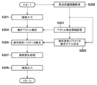
<防振処理>次に、図2を参照して、本実施形態の撮像装置による防振処理について説明する。 <Anti-Vibration Processing> Next, with reference to FIG. 2, the anti-vibration processing by the imaging apparatus of this embodiment will be described.
なお、図2の処理は、防振制御部106が、不図示の不揮発性メモリに格納されたファームウェアのプログラムを実行することにより実現される。
2 is realized by the image
図2において、ステップS201では、撮像光学系101から入力される被写体像が、撮像部102にて光電変換されて被写体輝度に応じたアナログ信号として現像処理部103に出力され、現像処理部103で映像信号が生成される。現像処理部103により所定のフレームレートで順次生成されるフレーム画像はメモリ104に保持されると共に、メモリ104に保持されたフレーム画像が動きベクトル検出部107に出力され、メモリ104に保持されるフレーム画像が順次更新される。
In FIG. 2, in step S <b> 201, the subject image input from the imaging
ステップS202では、撮影パラメータ取得部105が撮像光学系101のレンズの焦点距離情報を取得する。
In step S202, the imaging
ステップS203では、防振制御部106が、撮影パラメータ取得部105から得られる撮像装置の焦点距離情報に基づいて動きベクトル検出部107で検出された動きベクトルの検出領域および検出数を選択する。
In step S <b> 203, the image

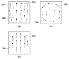
表1は、防振の対象とする像振れの動き成分と、その動き成分を精度良く補正するために必要となる動きベクトルの検出領域および動きベクトル検出数の関係を示している。図3は、像振れの動き成分と検出領域の関係を示している。表1からわかるように、防振の対象とする像振れの動き成分として、あおりの動きを補正する場合には、画面全域から多数の動きベクトルを検出する必要がある。その理由は以下の通りである。 Table 1 shows the relationship between the image blur motion component to be image-stabilized, the motion vector detection area and the number of motion vector detections necessary for accurately correcting the motion component. FIG. 3 shows the relationship between the image blur motion component and the detection area. As can be seen from Table 1, it is necessary to detect a large number of motion vectors from the entire screen when correcting the movement of the tilt as the motion component of the image blur that is the subject of image stabilization. The reason is as follows.
図3(a)はフレーム画像間で縦方向のあおりが発生している場合に検出される動きベクトルの大きさと方向を模式的に示しており、301はフレーム画像全体、302はあおりの動きを表す動きベクトル、303は動きベクトルの検出を行う領域を示している。図3(a)に示すように、あおりの動きは画像上の各位置において動きベクトルの大きさや方向が異なるため、画面全域から動きベクトルを検出しなければ、あおりの動きを精度良く推定することはできない。また、あおりのような複雑な動きに対しては多数の動きベクトルを用いなければ推定精度を安定化させることができない。このような理由により、あおりの動きを防振の対象とする場合には、検出領域303のようにフレーム画像の全域から多数の動きベクトルを検出する必要がある。
FIG. 3A schematically shows the magnitude and direction of a motion vector detected when vertical tilt occurs between frame images. 301 indicates the entire frame image, and 302 indicates the motion of the tilt. A motion vector to be represented, 303, indicates a region where motion vectors are detected. As shown in FIG. 3A, since the movement of the tilt is different in the magnitude and direction of the motion vector at each position on the image, if the motion vector is not detected from the entire screen, the movement of the tilt is accurately estimated. I can't. Further, for a complicated motion such as a tilt, the estimation accuracy cannot be stabilized unless a large number of motion vectors are used. For these reasons, when the movement of the tilt is targeted for image stabilization, it is necessary to detect a large number of motion vectors from the entire frame image like the
また、回転の動き成分を防振の対象とする場合には、画面の中央近辺の領域から動きベクトルを検出すれば良い。ここで、画像上に生じる回転の動きベクトルは、図3(b)の304に示すように画像中心を回転中心とした点対称の動きとなる。従って、回転の動きの推定には画像中心を基準として点対称の位置関係にある動きベクトル対を検出すれば良く、必ずしも画面全域から動きベクトルを検出する必要はない。つまり、図3(b)の305に示すような画像中心を含み、垂直方向が狭くなっている領域を動きベクトルの検出領域としても、回転の動きを検出するのに必要な動きベクトルを検出することできる。この場合、画像は上から下へ向かってラスタ的に入力されるため、検出領域305を画像の上部に配置することで画像全域の入力が完了するよりも早い時点で動きベクトルの検出を完了することができる。また、あおりの検出領域303と比較して検出領域が狭くなる分だけ、検出する動きベクトルの数を少なくすることができる。以上のことから、回転の動き成分を防振対象とすることで、あおりの動きを防振の対象とした場合よりも処理時間を短く、演算量を少なくすることができる。
In addition, in the case where the rotational motion component is the object of image stabilization, a motion vector may be detected from an area near the center of the screen. Here, the rotational motion vector generated on the image is a point-symmetrical motion with the center of the image as the rotational center, as indicated by 304 in FIG. Therefore, in order to estimate the rotational motion, it is only necessary to detect a motion vector pair having a point-symmetric positional relationship with respect to the image center, and it is not always necessary to detect a motion vector from the entire screen. That is, a motion vector necessary for detecting a rotational motion is detected even if an area including the image center as indicated by
これに対して、図3(c)の動きベクトル群306に示されるような並進の動きのみを防振の対象とする場合には、検出領域307のように画像上のごく一部の領域について動きベクトルの検出を行えば良い。撮像装置の支配的な動きが並進の動きである場合には、検出される動きベクトルは画像上のどの位置においても同じ大きさと方向を有している。従って、動きベクトルを検出する位置に制限がなく、さらに回転の動きよりも少ない数の動きベクトルからでも精度良く並進の動きを推定できる。また、回転の動きの場合とは異なり、点対称の位置関係で動きベクトルを検出する必要もないため、検出領域を画像のより上部に配置することが可能となる。これにより、並進の動きを推定する場合には更なる演算量の削減と処理時間の短縮を図ることが可能となる。
On the other hand, when only the translational motion as shown in the
上述したように、補正の対象とする像振れの動き成分の種類に応じて動きベクトルの検出領域および検出数を変更することで演算量を削減し、処理時間の短縮および消費電力を少なくすることが可能となる。 As described above, the amount of calculation is reduced by changing the detection area and the number of detections of the motion vector according to the type of the motion component of the image blur to be corrected, thereby shortening the processing time and power consumption. Is possible.
ここで、表1の上位に記載されている検出対象の像振れの動き成分は、それより下位にある像振れの動き成分を包含している。例えば、あおりの動きを対象とした動きベクトルの検出領域と検出数を選択した場合には、同時に回転および並進の幾何変形成分を推定するための動きベクトルを検出することが可能である。 Here, the image blur motion component of the detection target described at the top of Table 1 includes the image blur motion component at the lower level. For example, when a motion vector detection region and the number of detections for the tilt motion are selected, it is possible to detect a motion vector for estimating rotational and translational geometric deformation components at the same time.
本実施形態では、像ぶれの動き成分として、あおり、回転、並進に基づいて動きベクトルの検出領域と検出数を変更する例を説明したが、これに限るものではなく、例えば変倍(拡大/縮小)やせん断などの動き成分についても同様に適用できる。 In the present embodiment, the example in which the motion vector detection region and the number of detections are changed based on tilt, rotation, and translation as the motion component of the image blur has been described. However, the present invention is not limited to this. The same applies to motion components such as reduction and shear.
図2の説明に戻り、ステップS203で設定された動きベクトル検出領域および検出数の情報は動きベクトル検出部107へ送出される。
Returning to the description of FIG. 2, the information on the motion vector detection region and the number of detections set in step S <b> 203 is sent to the motion
ステップS204では、動きベクトル検出部107が、防振制御部106で設定された動きベクトル検出領域および検出数に基づいて、2枚のフレーム画像間での動きベクトルの検出を行う。本実施形態では、動きベクトル検出方法の一例としてテンプレートマッチングを用いた方法について説明する。
In step S204, the motion
図4はテンプレートマッチングを用いた動きベクトル検出方法を説明する図である。 FIG. 4 is a diagram for explaining a motion vector detection method using template matching.
図4(a)は原画像、図4(b)は参照画像を示しており、これらの画像は現像処理部103およびメモリ104から入力されるフレーム画像である。図示のように原画像中の任意の位置にテンプレートブロック401を配置し、テンプレートブロック401と参照画像の各領域との相関値を算出する。この場合、参照画像の全領域に対して相関値を算出するのでは演算量が膨大となるため、実際には参照画像上の相関値を算出する矩形領域をサーチ範囲402として設定する。ここで、サーチ範囲402の位置や大きさについては特に制限はないが、サーチ範囲402の内部にテンプレートブロック401の移動先に相当する領域が含まれていないと正しい動きベクトルを検出することはできない。
4A shows an original image, and FIG. 4B shows a reference image. These images are frame images input from the
本実施形態では、相関値の算出方法の一例として差分絶対値和(Sum of Absolute Difference、以下SADと略す)を使用する。SADは式1から求められる。 In this embodiment, a sum of absolute difference (hereinafter abbreviated as SAD) is used as an example of a correlation value calculation method. SAD is obtained from Equation 1.
式1において、f(i,j)はテンプレートブロック401内の座標(i,j)における輝度値を表し、g(i,j)はサーチ範囲402において相関値算出の対象となるブロック403内の各輝度値を表している。SADは、両ブロック内の各輝度値f(i,j)およびg(i,j)について差の絶対値を算出し、その総和を求めることで相関値S_SADを得ることができる。従って、相関値S_SADの値が小さいほど両ブロック間の輝度値の差分が小さい、つまりテンプレートブロック401と相関値算出領域のブロック403内のテクスチャが類似していることを意味する。
In Equation 1, f (i, j) represents the luminance value at the coordinates (i, j) in the
本実施形態では、相関値の一例としてSADを使用しているが、これに限るものではなく、差分二乗和(SSD)や正規化相互相関(NCC)などの他の相関値を用いても良い。この場合は、サーチ範囲402の全領域について相関値対象ブロック403を移動させて相関値を算出する。そしてテンプレートブロック401とサーチ範囲402との間で相関値を算出し、相関が最も高くなる位置を判定することにより、原画像上のテンプレートブロックが参照画像においてどの位置に移動したか、つまり画像間の動きベクトルを検出することができる。
In the present embodiment, SAD is used as an example of the correlation value, but the present invention is not limited to this, and other correlation values such as sum of squares of differences (SSD) and normalized cross-correlation (NCC) may be used. . In this case, the correlation value is calculated by moving the correlation
以上のような動きベクトルの検出処理を、入力されたフレーム画像間の複数の領域で行い、検出された動きベクトル群は幾何変形パラメータ推定部108に送出される。
The motion vector detection process as described above is performed in a plurality of regions between the input frame images, and the detected motion vector group is sent to the geometric deformation
ステップS205では、防振制御部106が、防振の対象とする像振れの動き成分の種類に応じて幾何変形パラメータの推定方法を選択する。本実施形態では、幾何変形を表す手段の一例としてホモグラフィ行列と呼ばれる3×3の行列式を用いる場合について説明する。
In step S <b> 205, the image
まず、画像上のある点a、 First, a certain point a on the image,
が次フレームにおいて点a′、 Is the point a ′ in the next frame,
に移動したとする。ここで、添え字Tは転置行列であること表す。式2の点aと式3の点a′の対応関係は、ホモグラフィ行列Hを用いることにより、 Suppose you move to. Here, the subscript T represents a transposed matrix. The correspondence between the point a in Equation 2 and the point a ′ in Equation 3 is obtained by using the homography matrix H:
と表すことができる。 It can be expressed as.
ホモグラフィ行列Hは画像間の並進、回転、変倍、せん断、あおりによる変形量を示す行列式であり、以下の式により表すことができる。 The homography matrix H is a determinant showing the amount of deformation caused by translation, rotation, scaling, shearing, and tilting between images, and can be expressed by the following equation.
ホモグラフィ行列Hの各要素は、ステップS204で得られる動きベクトル群、つまりフレーム画像間における代表点の対応関係を用いて推定処理を行うことにより求めることができる。 Each element of the homography matrix H can be obtained by performing an estimation process using the motion vector group obtained in step S204, that is, the correspondence of representative points between frame images.
表1に、防振対象とする像振れの動き成分に対する幾何変形パラメータの推定方法が示されている。表1から、あおりの動きを防振の対象とした場合には8自由度の最小二乗法を使用して、幾何変形パラメータを推定する必要がある。ここで、式5のホモグラフィ行列Hでは、パラメータh13、h23が並進の動き成分、h11、h12、h21、h22が回転、変倍、せん断の動き成分を表し、そしてh31、h32があおりの動き成分を表している。従って、あおりの動き成分を防振の対象とする場合には上記8個のパラメータ全てを推定しなければならないため、8自由度の最小二乗法を使用する必要がある。 Table 1 shows a method for estimating a geometric deformation parameter with respect to a motion component of image blur as an image stabilization target. From Table 1, it is necessary to estimate the geometric deformation parameter using the least-squares method with 8 degrees of freedom when the movement of the tilt is targeted for vibration isolation. Here, in the homography matrix H of Equation 5, parameters h13 and h23 represent translational motion components, h11, h12, h21 and h22 represent rotational, scaling, and shearing motion components, and h31 and h32 represent lateral motions. Represents ingredients. Therefore, when the tilt motion component is the object of image stabilization, it is necessary to use the 8-square degree least-squares method because all the 8 parameters must be estimated.
次に、回転の動き成分を防振の対象とする場合には、あおりの動き成分を表すパラメータであるh31およびh32を推定する必要がないため、それ以外の6個のパラメータを推定、つまり6自由度での最小二乗法による推定を行えば良いことになる。従って、補正する像振れの動き成分を回転の動き成分までとした場合には、あおりまでの場合と比較して自由度が少ない分、ベクトル数が少なくても安定した結果を得ることが可能であり、演算量を削減することができる。 Next, in the case where the rotational motion component is the object of image stabilization, it is not necessary to estimate h31 and h32 which are parameters representing the tilting motion component, so the other six parameters are estimated, that is, 6 It suffices to perform estimation by the least square method with degrees of freedom. Therefore, when the motion component of the image blur to be corrected is up to the rotational motion component, it is possible to obtain a stable result even if the number of vectors is small because the degree of freedom is smaller than in the case of tilting. Yes, the amount of calculation can be reduced.
そして、並進の動き成分のみを防振の対象とする場合には、式5におけるh13およびh23のパラメータについてのみ推定を行えば良い。また、並進の動き成分は画像の平行移動という簡単な動きであるため、最小二乗法のような統計的な推定方法を使用する必要はなく、ヒストグラム処理のような多数決処理でも精度良く推定を行うことが可能となる。 When only the translational motion component is the object of image stabilization, it is sufficient to estimate only the parameters h13 and h23 in Equation 5. In addition, since the translational motion component is a simple motion such as translation of the image, there is no need to use a statistical estimation method such as the least square method, and the estimation is performed with high accuracy even by majority processing such as histogram processing. It becomes possible.
さらに、画像上に生じているのが並進の動きのみであれば、画像上のどの位置においても同じ大きさ、同じ方向の動きとなるため、少ない数の動きベクトルでも精度良く並進の動きを推定することが可能である。 In addition, if only translational motion is occurring on the image, the motion will be the same in the same direction and in the same direction at any position on the image, so the translational motion can be accurately estimated with a small number of motion vectors. Is possible.
以上のように、並進の幾何変形量の推定では少ない動きベクトルによる単純な推定方法でパラメータの推定が可能であるため、演算量を大幅に削減することができる。 As described above, in the estimation of the translational geometric deformation amount, the parameter can be estimated by a simple estimation method using a small number of motion vectors, so that the calculation amount can be greatly reduced.
本実施形態では、幾何変形量の推定方法として最小二乗法やヒストグラム処理を用いているが、これに限られるものではなく他の推定手法を用いても良い。 In the present embodiment, the least square method or the histogram processing is used as the geometric deformation amount estimation method, but the present invention is not limited to this, and other estimation methods may be used.
ステップS205では、防振対象とする像振れの動き成分に応じて推定方法を変更することで演算量の削減を図っているが、総合的な演算量はステップS203で設定された動きベクトルの検出方法との組み合わせで決定される。表1から、あおりの動き成分に対しては画面全体から多くの動きベクトルを検出し、統計的な処理で式5に示した8個全ての幾何変形パラメータを求める必要があるため演算量は増大する。これに対して、例えば並進の幾何変形に対しては画面の一部の領域から少数の動きベクトルを検出すれば良く、さらに推定方法もヒストグラム処理のような単純なもので良いため演算量を大幅に削減することが可能である。 In step S205, the amount of calculation is reduced by changing the estimation method in accordance with the motion component of the image blur that is the object of image stabilization, but the total amount of calculation is the detection of the motion vector set in step S203. Determined in combination with the method. From Table 1, it is necessary to detect a large number of motion vectors from the entire screen for tilt motion components, and to calculate all eight geometric deformation parameters shown in Equation 5 by statistical processing, so that the amount of computation increases. To do. On the other hand, for example, for translational geometric deformation, it is sufficient to detect a small number of motion vectors from a partial area of the screen, and the estimation method can be as simple as histogram processing. Can be reduced.
上述のように選択された幾何変形量推定方法の情報は幾何変形パラメータ推定部108へ送出される。
Information on the geometric deformation amount estimation method selected as described above is sent to the geometric deformation
ステップS206では、動きベクトル検出部107から得られた動きベクトル群と、防振制御部106で選択された幾何変形量推定方法とを用いてフレーム画像間の幾何変形量の推定を行い、像振れの補正量を算出する。
In step S206, the amount of geometric deformation between the frame images is estimated using the motion vector group obtained from the motion
ステップS205で述べた方法で推定されたホモグラフィ行列Hは、画像の像振れによる画像の変形量を表す。このため、画像の像振れを補正するには、像振れによる変形を打ち消すような画像変形量となるようにホモグラフィ行列Hを変換する必要がある。つまり、ホモグラフィ行列Hを逆行列Hに変換することにより、点a′と点aの対応関係は、 The homography matrix H estimated by the method described in step S205 represents the amount of deformation of the image due to image blurring. For this reason, in order to correct the image blur of the image, it is necessary to convert the homography matrix H so that the image deformation amount cancels the deformation due to the image blur. That is, by converting the homography matrix H to the inverse matrix H, the correspondence between the points a ′ and a is
![]()
![]()
と表すことができる。式6により、像振れが生じた後の点a´を、像振れが生じる前の点aと同じ座標に戻すことが可能となる。 It can be expressed as. Expression 6 makes it possible to return the point a ′ after image blurring to the same coordinates as the point a before image blurring.
上述した実施形態によれば、防振対象とする像振れの動き成分の種類に応じて、動きベクトルの検出方法および幾何変形量の推定方法を切り替えることにより演算量を削減することができる。 According to the above-described embodiment, it is possible to reduce the amount of calculation by switching between the motion vector detection method and the geometric deformation amount estimation method according to the type of the motion component of the image blur that is the image stabilization target.
次に、防振対象とする像振れの動き成分の種類を判定する方法について説明する。 Next, a method for determining the type of motion component of image blur that is the object of image stabilization will be described.
本実施形態では、判定を行うための情報として、撮影パラメータ取得部105で得られる焦点距離情報を用いるため、像振れの動き成分の大きさと焦点距離との関係を考慮する必要がある。
In the present embodiment, since the focal length information obtained by the imaging
ここで、像振れの動き成分の大きさとは、像振れの動き成分を表すホモグラフィで画像を変形する場合に、画像上のある着目画素が移動する量を意味している。例えば、画像の四隅の点に対して、像振れの動き成分を表すホモグラフィによる移動量をそれぞれ求め、そのうち絶対値が最大のものを、その成分の大きさとする。 Here, the magnitude of the image blur motion component means the amount by which a pixel of interest on the image moves when the image is deformed by homography representing the image blur motion component. For example, with respect to the four corner points of the image, the movement amounts by homography representing the motion component of the image shake are respectively obtained, and the one having the maximum absolute value is set as the size of the component.
画像の像振れの動きを表すホモグラフィRは、ヨー方向、ピッチ方向、ロール方向の像振れ角度をα、β、γとすると、以下の式7のように表すことができる。 The homography R representing the image shake movement of the image can be expressed as the following Expression 7, where α, β, and γ are image shake angles in the yaw direction, the pitch direction, and the roll direction.
なお、ここでは簡単のため、撮像装置の回転の動きだけを考えたが、並進の動きを考慮した場合も、以下について同様のことが言える。 Here, for the sake of simplicity, only the rotational movement of the imaging device is considered, but the same can be said for the following when the translational movement is taken into consideration.
画像の像振れの動きを補正するためのホモグラフィは、式7の逆行列を取ることで、次のように表すことができる。 The homography for correcting the movement of the image shake of the image can be expressed as follows by taking the inverse matrix of Equation 7.
式8を簡略するため、(3,3)要素で正規化すると以下の式9のようになる。 In order to simplify Expression 8, when normalized by the (3, 3) element, the following Expression 9 is obtained.
さらに、撮影パラメータの影響を考慮するため、式10の撮影パラメータ行列Kを用いて正規化を行うと、式11のように表すことができる。 Furthermore, in order to consider the influence of the shooting parameters, when normalization is performed using the shooting parameter matrix K of Expression 10, it can be expressed as Expression 11.
ここで、fはピクセル単位の焦点距離、cx、cyは光軸中心のX座標、Y座標を表す。また簡単のためcx=cy=0として考えた。 Here, f represents the focal length in pixel units, and cx and cy represent the X coordinate and Y coordinate of the optical axis center. For simplicity, it was considered that cx = cy = 0.
ところで、画像の変形量を表すホモグラフィHは、並進、回転、変倍、せん断、あおりの各成分を用いて、以下の式12のように表すことができる。 By the way, the homography H representing the deformation amount of the image can be expressed as the following Expression 12 using the translation, rotation, zooming, shear, and tilt components.
ここで、Hsは並進、回転、変倍による画像の変形量を表すホモグラフィ、Haはせん断による画像の変形量を表すホモグラフィ、Hpはあおりによる画像の変形量を表すホモグラフィである。 Here, Hs is a homography that represents the amount of deformation of the image due to translation, rotation, and scaling, Ha is a homography that represents the amount of deformation of the image due to shear, and Hp is a homography that represents the amount of deformation of the image due to tilt.
また、vx、vyは水平方向と垂直方向のあおり成分、θは画像中心を基準とした回転成分、tx、tyは水平方向と垂直方向の並進成分、sは変倍成分、aおよびφはせん断成分を表す。 Also, vx and vy are horizontal and vertical tilt components, θ is a rotation component based on the image center, tx and ty are horizontal and vertical translation components, s is a magnification component, and a and φ are shearing Represents an ingredient.
式12は、式11のホモグラフィを、並進、回転、変倍、せん断、あおりの各成分を用いて表現したものと考えられる。両者は等価であるから、vx、vy、θ、tx、tyは、焦点距離fとα、β、γを用いて、以下のように表すことができる。 Expression 12 is considered to represent the homography of Expression 11 using translation, rotation, zooming, shearing, and tilt components. Since both are equivalent, vx, vy, θ, tx, and ty can be expressed as follows using the focal length f and α, β, and γ.
ここで、α、β、γが焦点距離に依存せず一定であれば、像振れの動き成分の大きさと焦点距離の関係について次のことが言える。 Here, if α, β, and γ are constant without depending on the focal length, the following can be said with respect to the relationship between the magnitude of the image blur motion component and the focal length.
式13から、あおり成分は焦点距離に反比例する。式14から、回転成分は焦点距離に依存せず一定である。式15から、並進成分は焦点距離に比例する。 From Equation 13, the tilt component is inversely proportional to the focal length. From Equation 14, the rotation component is constant regardless of the focal length. From Equation 15, the translational component is proportional to the focal length.
しかし、実際に撮像装置を使用する際は、焦点距離に応じて撮影方法が変化することで、α、β、γは、焦点距離が長くなるほど小さくなる傾向がある。 However, when the imaging apparatus is actually used, α, β, and γ tend to become smaller as the focal length becomes longer because the photographing method changes according to the focal length.
焦点距離が短い場合は、α、β、γが大きくなりやすい。なぜなら、画角(撮像装置で撮影できる範囲)が大きいため、画像の像振れが大きくても被写体が画面に収まりやすく、撮影者が意図的に像振れを抑えることが少ないためである。そのため、焦点距離が短い場合は、歩き撮りのような撮影方法が多くなり、α、β、γが大きくなる。 When the focal length is short, α, β, and γ tend to be large. This is because the angle of view (the range that can be captured by the imaging device) is large, so that even if the image shake of the image is large, the subject tends to fit on the screen, and the photographer does not intentionally suppress the image shake. For this reason, when the focal length is short, there are many photographing methods such as walk shooting, and α, β, and γ increase.
焦点距離が長い場合は、α、β、γが小さくなりやすい。なぜなら、画角が小さいため、画像の像振れが大きいと被写体が画面に収まらず、撮影者が意図的に像振れを抑えることが多いためである。そのため、焦点距離が長い場合には、両手持ち撮影のようにしっかりと固定した撮影方法が多くなり、α、β、γが小さくなる。 When the focal length is long, α, β, and γ tend to be small. This is because, since the angle of view is small, if the image blur of the image is large, the subject does not fit on the screen, and the photographer often intentionally suppress the image blur. Therefore, when the focal length is long, there are many photographing methods that are firmly fixed, such as two-handed photographing, and α, β, and γ are reduced.
焦点距離が中程度の場合は、短い場合と長い場合の中間に位置するので、片手持ち撮影のように、歩き撮りよりは像振れが小さく、両手持ち撮影よりは像振れが大きくなるような撮影方法が多くなり、α、β、γも中間的な値になると考える。 When the focal length is medium, it is positioned between the short and long cases, so that the image shake is smaller than the walk shot and the image shake is larger than the two-hand hold shot. The number of methods increases, and α, β, and γ are considered to be intermediate values.
最終的に、像振れの動き成分の大きさと焦点距離の関係は、α、β、γが、焦点距離が長くなるほど小さくなることを考慮すると、次のように考えられる。 Finally, the relationship between the magnitude of the image blur motion component and the focal length is considered as follows, considering that α, β, and γ become smaller as the focal length becomes longer.
あおり成分は、式13から焦点距離に反比例するが、焦点距離が長くなるほどα、βも小さくなるため、急激に小さくなる。回転成分は、式14からγそのもので、焦点距離が長くなるほど小さくなる。並進成分は、式15から焦点距離に比例するが、焦点距離が長くなるほどα、β、γが小さくなるため、両者が相殺し、焦点距離による変動は小さい。 The tilt component is inversely proportional to the focal length from Equation 13, but α and β become smaller as the focal length becomes longer, and therefore, the tilt component becomes abruptly smaller. The rotational component is γ itself from Equation 14, and decreases as the focal length increases. Although the translational component is proportional to the focal length from Equation 15, α, β, and γ decrease as the focal length increases, so that they cancel each other, and the variation due to the focal length is small.
表2は、像振れの動き成分と焦点距離の関係を示しており、表2から以下のことがわかる。すなわち、
焦点距離が短い場合には、あおり、回転、並進成分のいずれも大きい。一方、焦点距離が中程度の場合には、回転、並進成分は大きく、あおり成分は小さい。また、焦点距離が長い場合には、並進成分は大きく、あおりと回転の成分は小さい。
Table 2 shows the relationship between the motion component of image blur and the focal length, and Table 2 shows the following. That is,
When the focal length is short, the tilt, rotation, and translation components are large. On the other hand, when the focal length is medium, the rotation and translation components are large and the tilt component is small. When the focal length is long, the translation component is large and the tilt and rotation components are small.
従って、防振対象とする像振れの動き成分の種類の判定は、焦点距離に応じて以下のように行うべきである。
(1)焦点距離が所定の閾値T1より短い場合は、あおり、回転、並進成分の全ての成分を防振対象と判定する。
(2)焦点距離が所定の閾値T1とT2(T1<T2)の間である場合は、支配的な回転、並進成分だけを防振対象と判定する。
(3)焦点距離が所定の閾値T2より長い場合は、支配的な並進成分だけを防振対象と判定する。
Therefore, the determination of the type of the image blur motion component that is the object of image stabilization should be performed as follows according to the focal length.
(1) When the focal length is shorter than the predetermined threshold T1, all components of the tilt, rotation, and translation components are determined as the image stabilization targets.
(2) When the focal length is between the predetermined threshold values T1 and T2 (T1 <T2), only the dominant rotation and translation components are determined as the image stabilization target.
(3) When the focal length is longer than the predetermined threshold value T2, only the dominant translation component is determined as the image stabilization target.
上記判定結果に対して、動きベクトル検出方法および幾何変形パラメータ推定方法をどのように切り替えるかについては、表1で説明した通りである。 How the motion vector detection method and the geometric deformation parameter estimation method are switched with respect to the determination result is as described in Table 1.
以上のように、本実施形態によれば、支配的な像振れの動き成分の種類を、撮像装置の焦点距離情報から判定し、その判定結果に基づいて、動きベクトル検出方法および幾何変形パラメータ推定方法を切り替える。 As described above, according to the present embodiment, the type of the dominant image shake motion component is determined from the focal length information of the imaging apparatus, and the motion vector detection method and the geometric deformation parameter estimation are performed based on the determination result. Switch methods.
その結果、支配的な像振れを抑えた良好な防振を行いつつも、防振処理に要する演算量を減らし、消費電力を抑えることができる。 As a result, it is possible to reduce power consumption by reducing the amount of calculation required for the image stabilization process while performing excellent image stabilization with suppressed dominant image blur.
本実施形態によれば、焦点距離が長い状態が多いほど、動きベクトル検出領域を狭くし、さらに推定すべき幾何変形パラメータ数を減らすことができるので、演算量の削減、消費電力の抑圧が見込める。 According to this embodiment, as the focal length is longer, the motion vector detection area can be narrowed and the number of geometric deformation parameters to be estimated can be reduced, so that the amount of calculation can be reduced and the power consumption can be reduced. .
しかしながら、撮影中に防振処理内容をそのまま切り替えてしまうと、切り替えの前後で幾何変形のモデルが変わるため、不連続な動きが生じてしまう可能性がある。これを解消する方法の一例としては、幾何変形パラメータに時間的な平滑化処理を施す方法がある。 However, if the image stabilization processing contents are switched as they are during shooting, the geometric deformation model changes before and after the switching, and therefore, discontinuous movement may occur. As an example of a method for solving this, there is a method of performing a temporal smoothing process on the geometric deformation parameter.
これは、防振処理中は過去の数フレーム分の幾何変形パラメータを記憶しておき、切り替わった直後の数フレームについては過去の幾何変形パラメータの影響を考慮に入れた幾何変形パラメータを生成して防振処理を行う方法である。これにより、切り替えの瞬間の不連続を抑制し、徐々に異なる推定方法での防振結果に切り替わることが可能となる。ここで、平滑化の方法に特に制限はなく、移動平均や、IIRフィルタなど、どのような方法を用いても良い。以上の処理は幾何変形パラメータ推定部108において行われる。
This is because the geometric deformation parameters for the past several frames are stored during the image stabilization process, and the geometric deformation parameters taking into account the influence of the past geometric deformation parameters are generated for the few frames immediately after switching. This is a method for performing the image stabilization process. Thereby, it becomes possible to suppress discontinuity at the moment of switching and gradually switch to the image stabilization result by different estimation methods. Here, the smoothing method is not particularly limited, and any method such as a moving average or an IIR filter may be used. The above processing is performed in the geometric deformation
図2の説明に戻り、ステップS207では、ステップS206で得られた防振用の幾何変形量を用いて、幾何変形処理部109が画像に幾何変換処理を施すことで防振を行う。
Returning to the description of FIG. 2, in step S207, the geometric
ステップS208では防振処理が施された映像データを、画像記録部110によって記憶媒体に記憶したり、画像表示部111によって表示装置に表示する。
In step S208, the image data subjected to the image stabilization process is stored in a storage medium by the
以上説明したように、本実施形態によれば、撮像装置の焦点距離情報に応じて動きベクトルの検出方法および画像幾何変形量の推定方法を変更することで、防振処理に要する演算量を削減する。これにより、撮像装置の手振れに応じた効率的な防振処理を行うことが可能となり消費電力を削減することができる。 As described above, according to the present embodiment, the amount of calculation required for the image stabilization process is reduced by changing the motion vector detection method and the image geometric deformation amount estimation method according to the focal length information of the imaging device. To do. As a result, it is possible to perform an effective image stabilization process in accordance with the camera shake of the imaging apparatus, thereby reducing power consumption.
なお、本実施形態では撮影パラメータとして焦点距離を例に挙げたが、撮影パラメータとして焦点距離が得られないような場合などに、AFセンサにより得られた被写体距離を用いることもできる。この場合、被写体距離が近い場合は、被写体が画面に収まる大きさで写るようにするために、焦点距離を短くして撮影していると判定し、前述した焦点距離が短いときの防振処理を行う。一方、被写体距離が遠い場合は、被写体が画面に大きく写るようにするために、焦点距離を長くして撮影していると判定し、先述した焦点距離が長いときの防振処理を行う。 In this embodiment, the focal length is taken as an example of the shooting parameter, but the subject distance obtained by the AF sensor can also be used when the focal length cannot be obtained as the shooting parameter. In this case, when the subject distance is short, it is determined that the subject is shot with a short focal length so that the subject is captured in a size that fits on the screen, and the above-described image stabilization processing when the focal length is short I do. On the other hand, if the subject distance is long, it is determined that the subject is being photographed with a long focal length so that the subject is shown on the screen larger, and the above-described image stabilization processing is performed when the focal length is long.
上述した実施形態では、本発明をデジタルビデオカメラなどの撮像装置に適用した場合を例にして説明したが、これに限定されるものではない。例えば、ゲーム機器、携帯電話、スマートフォン、タブレット端末のように、撮影機能が搭載された装置にも本発明は適用可能である。また、パーソナルコンピュータなどの画像処理装置が、撮影機能を有する装置から取得した画像データを対象として、動きベクトルを検出し、像振れを補正するような構成であっても、本発明は適用可能である。 In the above-described embodiment, the case where the present invention is applied to an imaging apparatus such as a digital video camera has been described as an example. However, the present invention is not limited to this. For example, the present invention can be applied to an apparatus equipped with a photographing function such as a game machine, a mobile phone, a smartphone, and a tablet terminal. Further, the present invention can be applied even when an image processing device such as a personal computer is configured to detect a motion vector and correct image blur for image data acquired from a device having a photographing function. is there.
[その他の実施形態]
本発明は、以下の処理を実行することによっても実現される。即ち、本実施形態の機能を実現するソフトウェア(プログラム)を、ネットワーク又は各種記憶媒体を介してシステムあるいは装置に供給し、そのシステムあるいは装置のコンピュータ(またはCPUやMPUなど)がプログラムを読み出して実行する処理である。
[Other Embodiments]
The present invention is also realized by executing the following processing. That is, software (program) that realizes the functions of this embodiment is supplied to a system or apparatus via a network or various storage media, and a computer (or CPU, MPU, etc.) of the system or apparatus reads out and executes the program. It is processing to do.
Claims (11)
画像を撮影する撮像手段と、
前記撮像手段による撮影パラメータを取得する取得手段と、
前記撮像手段から得られる第1の画像と第2の画像から動きベクトルを検出する動きベクトル検出手段と、
前記動きベクトル検出手段により検出された動きベクトルを用いて、前記第1の画像と前記第2の画像の間の像振れを幾何変形パラメータとして推定する幾何変形パラメータ推定手段と、
前記幾何変形パラメータ推定手段により推定された幾何変形パラメータを用いて前記第1の画像と前記第2の画像に幾何変形を施して像振れを補正する幾何変形手段と、
前記撮影パラメータに基づいて、前記幾何変形パラメータ推定手段よる幾何変形パラメータ推定方法を変更する防振制御手段と、を有することを特徴とする撮像装置。 An imaging apparatus that corrects image shake of an image,
Imaging means for taking an image;
Obtaining means for obtaining imaging parameters by the imaging means;
Motion vector detection means for detecting a motion vector from the first image and the second image obtained from the imaging means;
Geometric deformation parameter estimation means for estimating an image shake between the first image and the second image as a geometric deformation parameter using the motion vector detected by the motion vector detection means;
Geometric deformation means for correcting image blur by performing geometric deformation on the first image and the second image using the geometric deformation parameter estimated by the geometric deformation parameter estimation means;
Based on said imaging parameters, before Symbol imaging apparatus comprising: the image stabilization control means, for changing the geometric deformation parameter estimation means according geometric deformation parameter estimation methods.
前記動きベクトルの検出領域の大きさは、前記動きベクトル検出手段が検出対象とする像振れの動き成分の種類が少ないほど小さくなり、
前記動きベクトルの検出数は、前記動きベクトル検出手段が検出対象とする像振れの動き成分の種類が少ないほど少なくなることを特徴とする請求項2に記載の撮像装置。 The motion component of image blur to be detected by the motion vector detection means includes at least one of translation, rotation, and tilt,
The size of the detection area of the motion vector becomes smaller as the number of types of image blur motion components to be detected by the motion vector detection means decreases.
The imaging apparatus according to claim 2, wherein the number of motion vectors detected decreases as the number of types of image blur motion components to be detected by the motion vector detection unit decreases.
前記防振制御手段は、前記撮影パラメータとして前記焦点距離が長いほど、前記動きベクトル検出手段が検出対象とする像振れの動き成分の種類が少なくなるように制御することを特徴とする請求項2または3に記載の撮像装置。 The shooting parameter includes either a focal length or a subject distance of the imaging device,
The image stabilization control means, the more the longer the focal length as the imaging parameters, the claim motion vector detecting means and controlling such type of motion component of image vibration detection target is reduced 2 Or the imaging device of 3 .
前記被写体距離が長い場合は、前記被写体距離が短い場合と比べて、前記防振の対象となる像振れの動き成分の種類が少なくなるように制御することを特徴とする請求項4に記載の撮像装置。 When the focal length cannot be obtained as the imaging parameter, the image stabilization control unit changes the motion vector detection method and the geometric deformation parameter estimation method using the subject distance,
5. The control according to claim 4, wherein when the subject distance is long, control is performed so that there are fewer types of motion components of the image blur that are subject to image stabilization than when the subject distance is short. Imaging device.
前記防振制御手段は、前記撮影パラメータとして前記焦点距離が長いほど、前記幾何変形パラメータ推定手段が算出する幾何変形パラメータの数が少なくなるように制御することを特徴とする請求項6に記載の撮像装置。 The shooting parameter includes either a focal length or a subject distance of the imaging device,
7. The image stabilization control unit according to claim 6, wherein the image stabilization control unit controls the number of geometric deformation parameters calculated by the geometric deformation parameter estimation unit to decrease as the focal length increases as the imaging parameter. Imaging device.
撮像手段による撮影パラメータを取得する取得ステップと、
前記撮像手段から得られる第1の画像と第2の画像から動きベクトルを検出する動きベクトル検出ステップと、
前記動きベクトル検出ステップにより検出された動きベクトルを用いて、前記第1の画像と前記第2の画像の間の像振れを幾何変形パラメータとして推定する幾何変形パラメータ推定ステップと、
前記幾何変形パラメータ推定ステップにより推定された幾何変形パラメータを用いて前記第1の画像と前記第2の画像に幾何変形を施して像振れを補正する幾何変形ステップと、
前記撮影パラメータに基づいて、前記幾何変形パラメータ推定ステップよる幾何変形パラメータ推定方法を変更する防振制御ステップと、を有することを特徴とする撮像装置の制御方法。 An image pickup apparatus control method for correcting image blur of an image,
An acquisition step of acquiring imaging parameters by the imaging means;
A motion vector detection step of detecting a motion vector from the first image and the second image obtained from the imaging means;
A geometric deformation parameter estimation step for estimating an image shake between the first image and the second image as a geometric deformation parameter using the motion vector detected by the motion vector detection step;
A geometric deformation step of correcting image blur by performing geometric deformation on the first image and the second image using the geometric deformation parameter estimated by the geometric deformation parameter estimating step;
Based on said imaging parameter, the control method of the preceding Symbol geometric deformation parameters and image stabilization control step of changing the estimation step by geometrical transformation parameter estimation method, an imaging apparatus characterized by having a.
Priority Applications (1)
| Application Number | Priority Date | Filing Date | Title |
|---|---|---|---|
| JP2013170818A JP6231816B2 (en) | 2013-08-20 | 2013-08-20 | IMAGING DEVICE, ITS CONTROL METHOD, PROGRAM, AND STORAGE MEDIUM |
Applications Claiming Priority (1)
| Application Number | Priority Date | Filing Date | Title |
|---|---|---|---|
| JP2013170818A JP6231816B2 (en) | 2013-08-20 | 2013-08-20 | IMAGING DEVICE, ITS CONTROL METHOD, PROGRAM, AND STORAGE MEDIUM |
Publications (3)
| Publication Number | Publication Date |
|---|---|
| JP2015041819A JP2015041819A (en) | 2015-03-02 |
| JP2015041819A5 JP2015041819A5 (en) | 2016-09-15 |
| JP6231816B2 true JP6231816B2 (en) | 2017-11-15 |
Family
ID=52695763
Family Applications (1)
| Application Number | Title | Priority Date | Filing Date |
|---|---|---|---|
| JP2013170818A Expired - Fee Related JP6231816B2 (en) | 2013-08-20 | 2013-08-20 | IMAGING DEVICE, ITS CONTROL METHOD, PROGRAM, AND STORAGE MEDIUM |
Country Status (1)
| Country | Link |
|---|---|
| JP (1) | JP6231816B2 (en) |
Families Citing this family (3)
| Publication number | Priority date | Publication date | Assignee | Title |
|---|---|---|---|---|
| JP6667268B2 (en) | 2015-11-26 | 2020-03-18 | キヤノン株式会社 | Motion vector detection device, control method therefor, and imaging device |
| JP6702729B2 (en) * | 2016-01-18 | 2020-06-03 | キヤノン株式会社 | Light emission control device, control method thereof, control program, and imaging device |
| CN115022548A (en) * | 2022-06-23 | 2022-09-06 | Oppo广东移动通信有限公司 | Control method, control device, electronic apparatus, and medium |
Family Cites Families (5)
| Publication number | Priority date | Publication date | Assignee | Title |
|---|---|---|---|---|
| US7646891B2 (en) * | 2002-12-26 | 2010-01-12 | Mitshubishi Denki Kabushiki Kaisha | Image processor |
| JP4958610B2 (en) * | 2007-04-06 | 2012-06-20 | キヤノン株式会社 | Image stabilization apparatus, imaging apparatus, and image stabilization method |
| JP5074322B2 (en) * | 2008-08-05 | 2012-11-14 | オリンパス株式会社 | Image processing apparatus, image processing method, image processing program, and imaging apparatus |
| JP2012085205A (en) * | 2010-10-14 | 2012-04-26 | Canon Inc | Image processing apparatus, imaging device, image processing method, and image processing program |
| JP6046931B2 (en) * | 2011-08-18 | 2016-12-21 | キヤノン株式会社 | Imaging apparatus and control method thereof |
-
2013
- 2013-08-20 JP JP2013170818A patent/JP6231816B2/en not_active Expired - Fee Related
Also Published As
| Publication number | Publication date |
|---|---|
| JP2015041819A (en) | 2015-03-02 |
Similar Documents
| Publication | Publication Date | Title |
|---|---|---|
| JP5205337B2 (en) | Target tracking device, image tracking device, operation control method thereof, and digital camera | |
| US10027909B2 (en) | Imaging device, imaging method, and image processing device | |
| US9467625B2 (en) | Imaging device capable of combining images | |
| JP5189678B2 (en) | Image stabilization apparatus and method for moving image | |
| US9906732B2 (en) | Image processing device, image capture device, image processing method, and program | |
| JP2008160300A (en) | Image processor, and imaging apparatus | |
| JP2013074313A (en) | Image processing device, image processing method, and program | |
| US20140368682A1 (en) | Real-time image processing method and device | |
| JP2017175364A (en) | Image processing device, imaging device, and control method of image processing device | |
| US8644555B2 (en) | Device and method for detecting movement of object | |
| JP6231816B2 (en) | IMAGING DEVICE, ITS CONTROL METHOD, PROGRAM, AND STORAGE MEDIUM | |
| JP2011239157A5 (en) | ||
| KR102592745B1 (en) | Posture estimating apparatus, posture estimating method and computer program stored in recording medium | |
| JP6282133B2 (en) | Imaging device, control method thereof, and control program | |
| JP6178646B2 (en) | Imaging apparatus and image shake correction processing method | |
| EP3836540B1 (en) | Image processing apparatus and image capturing apparatus | |
| JP6316030B2 (en) | Imaging apparatus and control method thereof | |
| JP6245847B2 (en) | Image processing apparatus and image processing method | |
| CN114449130A (en) | Multi-camera video fusion method and system | |
| US20110249130A1 (en) | Electronic camera | |
| JP6381212B2 (en) | Imaging apparatus and control method thereof | |
| JP5146223B2 (en) | Program, camera, image processing apparatus, and image contour extraction method | |
| JP6808446B2 (en) | Image processing equipment, image processing methods and programs | |
| JP7278737B2 (en) | IMAGING DEVICE, CONTROL METHOD THEREOF, AND PROGRAM | |
| JP2009290588A (en) | Motion vector detecting device and its method, and image pickup device |
Legal Events
| Date | Code | Title | Description |
|---|---|---|---|
| A521 | Request for written amendment filed |
Free format text: JAPANESE INTERMEDIATE CODE: A523 Effective date: 20160802 |
|
| A621 | Written request for application examination |
Free format text: JAPANESE INTERMEDIATE CODE: A621 Effective date: 20160802 |
|
| A131 | Notification of reasons for refusal |
Free format text: JAPANESE INTERMEDIATE CODE: A131 Effective date: 20170220 |
|
| A521 | Request for written amendment filed |
Free format text: JAPANESE INTERMEDIATE CODE: A523 Effective date: 20170418 |
|
| TRDD | Decision of grant or rejection written | ||
| A01 | Written decision to grant a patent or to grant a registration (utility model) |
Free format text: JAPANESE INTERMEDIATE CODE: A01 Effective date: 20170922 |
|
| A61 | First payment of annual fees (during grant procedure) |
Free format text: JAPANESE INTERMEDIATE CODE: A61 Effective date: 20171020 |
|
| R151 | Written notification of patent or utility model registration |
Ref document number: 6231816 Country of ref document: JP Free format text: JAPANESE INTERMEDIATE CODE: R151 |
|
| LAPS | Cancellation because of no payment of annual fees |