JP4755490B2 - Blur correction method and imaging apparatus - Google Patents
Blur correction method and imaging apparatus Download PDFInfo
- Publication number
- JP4755490B2 JP4755490B2 JP2005352376A JP2005352376A JP4755490B2 JP 4755490 B2 JP4755490 B2 JP 4755490B2 JP 2005352376 A JP2005352376 A JP 2005352376A JP 2005352376 A JP2005352376 A JP 2005352376A JP 4755490 B2 JP4755490 B2 JP 4755490B2
- Authority
- JP
- Japan
- Prior art keywords
- image
- target pixel
- pixel block
- vector
- target
- Prior art date
- Legal status (The legal status is an assumption and is not a legal conclusion. Google has not performed a legal analysis and makes no representation as to the accuracy of the status listed.)
- Expired - Fee Related
Links
- 238000003384 imaging method Methods 0.000 title claims abstract description 71
- 238000012937 correction Methods 0.000 title claims abstract description 69
- 238000000034 method Methods 0.000 title claims description 116
- 239000013598 vector Substances 0.000 claims abstract description 227
- 230000009466 transformation Effects 0.000 claims abstract description 47
- PXFBZOLANLWPMH-UHFFFAOYSA-N 16-Epiaffinine Natural products C1C(C2=CC=CC=C2N2)=C2C(=O)CC2C(=CC)CN(C)C1C2CO PXFBZOLANLWPMH-UHFFFAOYSA-N 0.000 claims abstract description 35
- 230000002093 peripheral effect Effects 0.000 claims abstract description 7
- 238000012545 processing Methods 0.000 claims description 99
- 230000008569 process Effects 0.000 claims description 64
- 238000006243 chemical reaction Methods 0.000 claims description 46
- 238000000605 extraction Methods 0.000 claims description 35
- 239000011159 matrix material Substances 0.000 claims description 33
- 239000000284 extract Substances 0.000 claims description 17
- 230000003287 optical effect Effects 0.000 claims description 14
- 230000006835 compression Effects 0.000 claims description 5
- 238000007906 compression Methods 0.000 claims description 5
- 230000005484 gravity Effects 0.000 claims description 4
- 238000013459 approach Methods 0.000 claims description 3
- 230000001131 transforming effect Effects 0.000 claims 1
- 230000014509 gene expression Effects 0.000 description 12
- 238000004891 communication Methods 0.000 description 10
- 238000010586 diagram Methods 0.000 description 10
- 238000011156 evaluation Methods 0.000 description 10
- 230000006870 function Effects 0.000 description 4
- 238000012986 modification Methods 0.000 description 4
- 230000004048 modification Effects 0.000 description 4
- 238000003702 image correction Methods 0.000 description 3
- 238000003672 processing method Methods 0.000 description 3
- 230000008859 change Effects 0.000 description 2
- 238000001514 detection method Methods 0.000 description 2
- 239000004973 liquid crystal related substance Substances 0.000 description 2
- 230000035945 sensitivity Effects 0.000 description 2
- 238000000926 separation method Methods 0.000 description 2
- 239000006185 dispersion Substances 0.000 description 1
- 238000005401 electroluminescence Methods 0.000 description 1
- 230000007246 mechanism Effects 0.000 description 1
- 238000013519 translation Methods 0.000 description 1
Images
Classifications
-
- G06T5/73—
-
- G—PHYSICS
- G06—COMPUTING; CALCULATING OR COUNTING
- G06T—IMAGE DATA PROCESSING OR GENERATION, IN GENERAL
- G06T5/00—Image enhancement or restoration
- G06T5/50—Image enhancement or restoration by the use of more than one image, e.g. averaging, subtraction
-
- H—ELECTRICITY
- H04—ELECTRIC COMMUNICATION TECHNIQUE
- H04N—PICTORIAL COMMUNICATION, e.g. TELEVISION
- H04N23/00—Cameras or camera modules comprising electronic image sensors; Control thereof
- H04N23/60—Control of cameras or camera modules
- H04N23/68—Control of cameras or camera modules for stable pick-up of the scene, e.g. compensating for camera body vibrations
- H04N23/681—Motion detection
- H04N23/6811—Motion detection based on the image signal
-
- H—ELECTRICITY
- H04—ELECTRIC COMMUNICATION TECHNIQUE
- H04N—PICTORIAL COMMUNICATION, e.g. TELEVISION
- H04N23/00—Cameras or camera modules comprising electronic image sensors; Control thereof
- H04N23/60—Control of cameras or camera modules
- H04N23/68—Control of cameras or camera modules for stable pick-up of the scene, e.g. compensating for camera body vibrations
- H04N23/682—Vibration or motion blur correction
- H04N23/683—Vibration or motion blur correction performed by a processor, e.g. controlling the readout of an image memory
-
- G—PHYSICS
- G06—COMPUTING; CALCULATING OR COUNTING
- G06T—IMAGE DATA PROCESSING OR GENERATION, IN GENERAL
- G06T2207/00—Indexing scheme for image analysis or image enhancement
- G06T2207/10—Image acquisition modality
- G06T2207/10016—Video; Image sequence
-
- G—PHYSICS
- G06—COMPUTING; CALCULATING OR COUNTING
- G06T—IMAGE DATA PROCESSING OR GENERATION, IN GENERAL
- G06T2207/00—Indexing scheme for image analysis or image enhancement
- G06T2207/20—Special algorithmic details
- G06T2207/20021—Dividing image into blocks, subimages or windows
Abstract
Description
本発明は、画像のブレを補正するブレ補正方法と、このブレ補正方法を用い、被写体像を撮像するとともに撮像した画像のブレを補正する撮像装置とに関し、特に動画像のブレ補正および撮像に適用して好適なブレ補正方法および撮像装置に関するものである。 The present invention relates to a blur correction method for correcting blur of an image and an imaging apparatus that uses this blur correction method to capture a subject image and correct blur of the captured image, and more particularly to blur correction and imaging of a moving image. The present invention relates to a shake correction method and an imaging apparatus that are suitable for application.
従来、回転を含む位置ずれを検出して2つの画像の位置合わせを行う位置合わせ装置が知られている(たとえば、特許文献1参照)。この位置合わせ装置は、位置合わせの基準となる基準画像を複数の画素ブロックに分割してブロックマッチング処理を行い、基準画像と位置合わせの対象となる対象画像との間の回転を含む位置ずれを検出し、この検出結果をもとに2つの画像の位置合わせを行うようにしている。また、この位置合わせ装置は、分割した各画素ブロックの濃度分布の分散を求め、求めた分散値が所定の閾値以下の画素ブロックではブロックマッチング処理は誤った結果を導く可能性が高いものと判断し、対応する画素ブロックをブロックマッチング処理の対象から除外して、位置ずれの検出精度を向上させるようにしている。 2. Description of the Related Art Conventionally, there has been known an alignment device that detects misalignment including rotation and aligns two images (see, for example, Patent Document 1). This alignment apparatus divides a reference image serving as a reference for alignment into a plurality of pixel blocks, performs block matching processing, and detects a positional shift including rotation between the reference image and a target image to be aligned. Then, based on the detection result, the two images are aligned. In addition, this alignment device calculates the variance of the density distribution of each divided pixel block, and determines that the block matching process is likely to lead to an erroneous result for pixel blocks whose calculated variance value is equal to or less than a predetermined threshold. Then, the corresponding pixel block is excluded from the target of the block matching process, so that the detection accuracy of the positional deviation is improved.
しかしながら、上述した従来の位置合わせ装置では、各画素ブロックの濃度分布の分散のみによってブロックマッチング処理に対する信頼度を判断し、信頼度が低いと判断した画素ブロックを処理対象から除外する一方で、信頼度が高いと判断した画素ブロックのすべてを等しい信頼度で処理するようにしているため、撮像する被写体によっては必ずしも高い精度で2つの画像間の位置ずれを検出することができないという問題があった。 However, in the conventional alignment apparatus described above, the reliability of the block matching process is determined only by the distribution of the density distribution of each pixel block, and the pixel block determined to be low in reliability is excluded from the processing target, while the reliability is determined. Since all the pixel blocks determined to have a high degree are processed with equal reliability, there is a problem in that a positional deviation between two images cannot always be detected with high accuracy depending on the subject to be imaged. .
本発明は、上記に鑑みてなされたものであって、分割した画素ブロックの種々の特性値をもとに、ブロックマッチング処理等によって演算される各画素ブロックの動きベクトルの信頼度を判断し、この信頼度に応じた動きベクトルの演算処理を行って、常に高い精度で2つの画像間の位置ずれを検出できるようにするとともに、この位置ずれに対応した画像のブレを正確に補正することができるブレ補正方法および撮像装置を提供することを目的とする。 The present invention has been made in view of the above, and based on various characteristic values of the divided pixel blocks, the reliability of the motion vector of each pixel block calculated by block matching processing or the like is determined, By performing motion vector calculation processing according to this reliability, it is possible to detect a positional deviation between two images with high accuracy at all times, and to accurately correct image blur corresponding to this positional deviation. An object of the present invention is to provide a blur correction method and an image pickup apparatus that can be used.
上記の目的を達成するために、本発明にかかるブレ補正方法は、撮像装置によって撮像された複数の画像の中から、画像のブレを補正する対象となる対象画像および該補正の基準となる基準画像を選択する画像選択ステップと、前記対象画像から、少なくとも2つの対象画素ブロックを抽出するブロック抽出ステップと、前記ブロック抽出ステップによって抽出された各対象画素ブロックの位置に対応する前記基準画像上の位置から該各対象画素ブロックの位置までの移動量を示す動きベクトルを演算するベクトル演算ステップと、前記ベクトル演算ステップによって演算された各動きベクトルの前記画像のブレに対する信頼度をもとに、前記各対象画素ブロックの重み付け係数を設定する重み設定ステップと、所定の座標原点を基準とした前記各対象画素ブロックの位置ベクトル、前記各動きベクトルおよび前記重み設定ステップによって設定された各重み付け係数をもとに、前記対象画像をアフィン変換するための変換係数を演算する係数演算ステップと、前記係数演算ステップの演算結果をもとに前記対象画像をアフィン変換して該対象画像のブレを補正する補正演算ステップと、を含むことを特徴とする。 In order to achieve the above object, a blur correction method according to the present invention includes a target image that is a target for correcting blur of an image among a plurality of images captured by an imaging device, and a reference that is a reference for the correction. An image selection step for selecting an image, a block extraction step for extracting at least two target pixel blocks from the target image, and a position on the reference image corresponding to the position of each target pixel block extracted by the block extraction step A vector calculation step of calculating a motion vector indicating a movement amount from the position to the position of each target pixel block, and the reliability of the motion vector calculated by the vector calculation step with respect to blurring of the image, A weight setting step for setting a weighting coefficient for each target pixel block and a predetermined coordinate origin as a reference A coefficient calculation step for calculating a conversion coefficient for affine transformation of the target image based on the position vector of each target pixel block, each motion vector, and each weighting coefficient set by the weight setting step; And a correction calculation step of correcting the blur of the target image by affine transformation of the target image based on the calculation result of the coefficient calculation step.
また、本発明にかかるブレ補正方法は、上記の発明において、前記対象画像を複数の画素エリアに分割するエリア分割ステップを含み、前記ブロック抽出ステップは、前記エリア分割ステップによって分割された複数の画素エリアから少なくとも2つの前記対象画素ブロックを抽出することを特徴とする。 The blur correction method according to the present invention includes, in the above invention, an area dividing step of dividing the target image into a plurality of pixel areas, wherein the block extracting step includes a plurality of pixels divided by the area dividing step. At least two target pixel blocks are extracted from an area.
また、本発明にかかるブレ補正方法は、上記の発明において、前記対象画像は、予め複数の画素エリアに分割された画像であり、前記ブロック抽出ステップは、予め分割された前記複数の画素エリアから少なくとも2つの前記対象画素ブロックを抽出することを特徴とする。 In the blur correction method according to the present invention, in the above invention, the target image is an image previously divided into a plurality of pixel areas, and the block extraction step is performed based on the plurality of pixel areas divided in advance. At least two of the target pixel blocks are extracted.
また、本発明にかかるブレ補正方法は、上記の発明において、前記重み設定ステップは、前記対象画像内の前記対象画素ブロックの位置に対応した前記信頼度をもとに、前記対象画素ブロックに対する前記重み付け係数を設定することを特徴とする。 Further , the blur correction method according to the present invention is the blur correction method according to the above invention, wherein the weight setting step is based on the reliability corresponding to the position of the target pixel block in the target image. A weighting coefficient is set.
また、本発明にかかるブレ補正方法は、上記の発明において、前記重み設定ステップは、前記対象画像の略中央部に位置する前記対象画素ブロックに対する前記重み付け係数に比して、前記対象画像内の周辺部に位置する前記対象画素ブロックに対する前記重み付け係数を大きく設定することを特徴とする。 Further , the blur correction method according to the present invention is the blur correction method according to the above invention, wherein the weight setting step is performed in the target image as compared with the weighting coefficient for the target pixel block located at a substantially central portion of the target image. The weighting coefficient for the target pixel block located in the peripheral portion is set to be large.
また、本発明にかかるブレ補正方法は、上記の発明において、前記重み設定ステップは、前記動きベクトルの方向および大きさの少なくとも一方に基づいた前記信頼度をもとに、前記対象画素ブロックに対する前記重み付け係数を設定することを特徴とする。 Also, the blur correction method according to the present invention is the blur correction method according to the above invention, wherein the weight setting step is based on the reliability based on at least one of the direction and the magnitude of the motion vector. A weighting coefficient is set.
また、本発明にかかるブレ補正方法は、上記の発明において、前記対象画素ブロック内の画像のコントラストを演算するコントラスト演算ステップを含み、前記重み設定ステップは、前記コントラスト演算ステップの演算結果に基づいた前記信頼度をもとに、前記対象画素ブロックに対する前記重み付け係数を設定することを特徴とする。 The blur correction method according to the present invention includes a contrast calculation step of calculating a contrast of an image in the target pixel block in the above invention, wherein the weight setting step is based on a calculation result of the contrast calculation step. The weighting coefficient for the target pixel block is set based on the reliability.
また、本発明にかかるブレ補正方法は、上記の発明において、前記対象画素ブロックの近傍に位置する近傍画素ブロックの前記動きベクトルを演算する近傍ベクトル演算ステップと、前記対象画素ブロックの動きベクトルに対する前記近傍画素ブロックの動きベクトルのばらつき程度を示す発散度を演算する発散度演算ステップと、を含み、前記重み設定ステップは、前記発散度演算ステップの演算結果に基づいた前記信頼度をもとに、前記対象画素ブロックに対する前記重み付け係数を設定することを特徴とする。 According to the blur correction method of the present invention, in the above invention, a neighborhood vector computing step of computing the motion vector of a neighboring pixel block located in the vicinity of the target pixel block, and the motion vector of the target pixel block A divergence degree calculating step for calculating a divergence degree indicating the degree of variation in motion vectors of neighboring pixel blocks, and the weight setting step is based on the reliability based on the calculation result of the divergence degree calculating step. The weighting coefficient for the target pixel block is set.
また、本発明にかかるブレ補正方法は、上記の発明において、前記係数演算ステップは、前記各対象画素ブロックに対応する前記各位置ベクトル、前記各動きベクトルおよび前記各重み付け係数をそれぞれXi(i=1,2,・・・,n)、Vi(i=1,2,・・・,n)およびwi(i=1,2,・・・,n)とし、該各重み付け係数の総和をwとした場合、前記各位置ベクトルの重み付き重心を示す位置重心ベクトルXcをXc=(w1・X1+w2・X2+・・・+wn・Xn)/wによって演算し、前記各動きベクトルの重み付き重心を示す動き重心ベクトルVcをVc=(w1・V1+w2・V2+・・・+wn・Vn)/wによって演算し、前記変換係数の線形変換成分に対応する回転マトリックスの回転角φを数式1によって演算することを特徴とする。 In the blur correction method according to the present invention as set forth in the invention described above, in the coefficient calculation step, each position vector, each motion vector, and each weighting coefficient corresponding to each target pixel block is represented by X i (i = 1, 2,..., N), V i (i = 1, 2,..., N) and w i (i = 1, 2,..., N). When the sum is w, the position centroid vector X c indicating the weighted centroid of each position vector is expressed by X c = (w 1 · X 1 + w 2 · X 2 +... + W n · X n ) / w The motion centroid vector V c indicating the weighted centroid of each motion vector is calculated by V c = (w 1 · V 1 + w 2 · V 2 +... + W n · V n ) / w, The rotation angle φ of the rotation matrix corresponding to the linear conversion component of the conversion coefficient is calculated by Equation 1. And wherein the Rukoto.

また、本発明にかかるブレ補正方法は、上記の発明において、前記係数演算ステップは、前記変換係数のシフト成分に対応するシフトベクトルSをS=Xc−Vcによって演算し、前記補正演算ステップは、前記回転マトリックスによって前記位置ベクトルの重み付き重心を中心に前記回転角だけ反時計周りに前記対象画像を回転した後、前記シフトベクトルによって該対象画像をシフトすることを特徴とする。 In the blur correction method according to the present invention, in the above invention, the coefficient calculation step calculates a shift vector S corresponding to a shift component of the transform coefficient by S = X c −V c , and the correction calculation step Is characterized in that the target image is rotated counterclockwise by the rotation angle around the weighted center of gravity of the position vector by the rotation matrix, and then the target image is shifted by the shift vector.
また、本発明にかかるブレ補正方法は、上記の発明において、前記ブロック抽出ステップおよび前記重み設定ステップは、前記位置重心ベクトルがゼロベクトルとなるように、それぞれ前記対象画素ブロックを抽出し、前記重み付け係数を設定することを特徴とする。 In the blur correction method according to the present invention, in the above invention, the block extraction step and the weight setting step each extract the target pixel block so that the position centroid vector becomes a zero vector, and the weighting step. A coefficient is set.
また、本発明にかかるブレ補正方法は、上記の発明において、前記係数演算ステップは、前記回転角φだけ反時計回りに回転変換を行う前記回転マトリックスをR(φ)として、前記変換係数のシフト成分に対応するシフトベクトルSをS=R(−φ)・(Xc−Vc)−Xcによって演算し、前記補正演算ステップは、前記シフトベクトルによって前記対象画像をシフトした後、前記回転マトリックスによって前記座標原点を中心に前記回転角だけ反時計方向に該対象画像を回転することを特徴とする。 In the blur correction method according to the present invention, in the above invention, in the coefficient calculation step, the rotation matrix for performing the rotation conversion counterclockwise by the rotation angle φ is R (φ), and the conversion coefficient is shifted. A shift vector S corresponding to a component is calculated by S = R (−φ) · (X c −V c ) −X c , and the correction calculation step shifts the target image by the shift vector and then rotates the rotation The target image is rotated counterclockwise by the rotation angle around the coordinate origin by a matrix.
また、本発明にかかるブレ補正方法は、上記の発明において、前記係数演算ステップは、前記各動きベクトルの大きさが所定値よりも小さい場合、数式1を近似した数式2によって前記回転角φを演算することを特徴とする。
In the blur correction method according to the present invention as set forth in the invention described above, the coefficient calculation step determines the rotation angle φ according to
また、本発明にかかるブレ補正方法は、上記の発明において、前記ブロック抽出ステップは、前記対象画像の各隅に位置する隅領域のうち異なる2つの該隅領域のそれぞれから前記対象画素ブロックを抽出し、前記係数演算ステップは、前記2つの隅領域から抽出された対象画素ブロックのうち一方の対象画素ブロックの位置を前記座標原点とし、該座標原点に位置する前記対象画素ブロックに対応する前記位置ベクトル、前記動きベクトルおよび前記重み付け係数をそれぞれX1,V1およびw1とし、前記重み設定ステップによって、前記座標原点に位置する対象画素ブロックに対する前記重み付け係数および他方の対象画素ブロックに対する前記重み付け係数がそれぞれ1および0に限りなく近づけられた場合、数式1を近似した数式3によって前記回転角φを演算することを特徴とする。 In the blur correction method according to the present invention as set forth in the invention described above, the block extraction step extracts the target pixel block from each of two different corner areas among the corner areas located at each corner of the target image. In the coefficient calculation step, the position of one target pixel block of the target pixel blocks extracted from the two corner regions is set as the coordinate origin, and the position corresponding to the target pixel block located at the coordinate origin vector, wherein the motion X 1 vector and the weighting factor, respectively, V 1 and w 1, by said weight setting step, said weighting factor for the weighting factors and other target pixel block with respect to the target pixel block located at the coordinate origin Is approximated to 1 and 0 as much as possible. To calculate the rotation angle φ.
また、本発明にかかるブレ補正方法は、上記の発明において、前記複数の画像は、動画像であり、前記各対象画素ブロックは、前記動画像の圧縮符号化処理中に行われるフレーム間予測処理の処理対象となるブロックであり、前記各動きベクトルは、前記フレーム間予測処理中に演算されることを特徴とする。 In the blur correction method according to the present invention, in the above invention, the plurality of images are moving images, and each of the target pixel blocks is an inter-frame prediction process performed during the compression encoding process of the moving images. The motion vectors are calculated during the inter-frame prediction process.
また、本発明にかかる撮像装置は、被写体からの光を集光して被写体像を結像する撮像光学系と、前記被写体像に対応する画像を撮像する撮像手段と、前記撮像手段によって撮像された複数の画像の中から、画像のブレを補正する対象となる対象画像および該補正の基準となる基準画像を選択する画像選択手段と、前記対象画像から、少なくとも2つの対象画素ブロックを抽出するブロック抽出手段と、前記ブロック抽出手段によって抽出された各対象画素ブロックの位置に対応する前記基準画像上の位置から該各対象画素ブロックの位置までの移動量を示す動きベクトルを演算するベクトル演算手段と、前記ベクトル演算手段によって演算された各動きベクトルの前記画像のブレに対する信頼度をもとに、前記各対象画素ブロックの重み付け係数を設定する重み設定手段と、所定の座標原点を基準とした前記各対象画素ブロックの位置ベクトル、前記各動きベクトルおよび前記重み設定手段によって設定された各重み付け係数をもとに、前記対象画像をアフィン変換するための変換係数を演算する係数演算手段と、前記係数演算手段の演算結果をもとに前記対象画像をアフィン変換して該対象画像のブレを補正する補正演算手段と、を備えたことを特徴とする。 The imaging apparatus according to the present invention is imaged by an imaging optical system that focuses light from a subject to form a subject image, an imaging unit that captures an image corresponding to the subject image, and the imaging unit. An image selection unit that selects a target image that is a target for correcting image blur and a reference image that is a reference for the correction, and at least two target pixel blocks are extracted from the target image. Block extraction means and vector calculation means for calculating a motion vector indicating a movement amount from a position on the reference image corresponding to the position of each target pixel block extracted by the block extraction means to the position of each target pixel block And weighting of each target pixel block based on the reliability of each motion vector calculated by the vector calculation means against blurring of the image A weight setting means for setting a coefficient, and a position vector of each target pixel block based on a predetermined coordinate origin, each motion vector, and each weighting coefficient set by the weight setting means based on the target image Coefficient calculating means for calculating a conversion coefficient for affine transformation, and correction calculating means for correcting blur of the target image by affine transformation of the target image based on the calculation result of the coefficient calculating means. It is characterized by that.
また、本発明にかかる撮像装置は、上記の発明において、前記対象画像を複数の画素エリアに分割するエリア分割手段を含み、前記ブロック抽出手段は、前記エリア分割手段によって分割された複数の画素エリアから少なくとも2つの前記対象画素ブロックを抽出することを特徴とする。 The imaging apparatus according to the present invention includes, in the above invention, an area dividing unit that divides the target image into a plurality of pixel areas, and the block extracting unit includes a plurality of pixel areas divided by the area dividing unit. And extracting at least two of the target pixel blocks.
また、本発明にかかる撮像装置は、上記の発明において、前記対象画像は、予め複数の画素エリアに分割された画像であり、前記ブロック抽出手段は、予め分割された前記複数の画素エリアから少なくとも2つの前記対象画素ブロックを抽出することを特徴とする。 In the imaging device according to the present invention, in the above invention, the target image is an image that has been divided into a plurality of pixel areas in advance, and the block extraction unit includes at least the plurality of pixel areas that have been divided in advance. Two target pixel blocks are extracted.
また、本発明にかかる撮像装置は、上記の発明において、前記重み設定手段は、前記動きベクトルの方向および大きさの少なくとも一方に基づいた前記信頼度をもとに、前記対象画素ブロックに対する前記重み付け係数を設定することを特徴とする。 In the imaging device according to the present invention as set forth in the invention described above, the weight setting unit may weight the target pixel block based on the reliability based on at least one of the direction and the magnitude of the motion vector. A coefficient is set.
また、本発明にかかる撮像装置は、上記の発明において、前記対象画素ブロック内の画像のコントラストを演算するコントラスト演算手段を含み、前記重み設定手段は、前記コントラスト演算手段の演算結果に基づいた前記信頼度をもとに、前記対象画素ブロックに対する前記重み付け係数を設定することを特徴とする。 The imaging apparatus according to the present invention includes, in the above invention, a contrast calculation unit that calculates a contrast of an image in the target pixel block, and the weight setting unit is based on a calculation result of the contrast calculation unit. The weighting coefficient for the target pixel block is set based on the reliability.
また、本発明にかかる撮像装置は、上記の発明において、前記対象画素ブロックの近傍に位置する近傍画素ブロックの前記動きベクトルを演算する近傍ベクトル演算手段と、前記対象画素ブロックの動きベクトルに対する前記近傍画素ブロックの動きベクトルのばらつき程度を示す発散度を演算する発散度演算手段と、を含み、前記重み設定手段は、前記発散度演算手段の演算結果に基づいた前記信頼度をもとに、前記対象画素ブロックに対する前記重み付け係数を設定することを特徴とする。 In the imaging device according to the present invention, in the above invention, a neighborhood vector computing unit that computes the motion vector of a neighboring pixel block located in the vicinity of the target pixel block; and the neighborhood of the motion vector of the target pixel block A divergence degree calculating means for calculating a divergence degree indicating a degree of variation of the motion vector of the pixel block, wherein the weight setting means is based on the reliability based on the calculation result of the divergence degree calculating means. The weighting coefficient for the target pixel block is set.
また、本発明にかかる撮像装置は、上記の発明において、前記係数演算手段は、前記各対象画素ブロックに対応する前記各位置ベクトル、前記各動きベクトルおよび前記各重み付け係数をそれぞれXi(i=1,2,・・・,n)、Vi(i=1,2,・・・,n)およびwi(i=1,2,・・・,n)とし、該各重み付け係数の総和をwとした場合、前記各位置ベクトルの重み付き重心を示す位置重心ベクトルXcをXc=(w1・X1+w2・X2+・・・+wn・Xn)/wによって演算し、前記各動きベクトルの重み付き重心を示す動き重心ベクトルVcをVc=(w1・V1+w2・V2+・・・+wn・Vn)/wによって演算し、前記変換係数の線形変換成分に対応する回転マトリックスの回転角φを数式4によって演算することを特徴とする。 In the image pickup apparatus according to the present invention, in the above invention, the coefficient calculation means sets the position vectors, the motion vectors, and the weighting coefficients corresponding to the target pixel blocks to X i (i = , N), V i (i = 1, 2,..., N) and w i (i = 1, 2,..., N), and the sum of the respective weighting coefficients Where w is the position centroid vector X c indicating the weighted centroid of each position vector, calculated by X c = (w 1 · X 1 + w 2 · X 2 +... + W n · X n ) / w The motion centroid vector V c indicating the weighted centroid of each motion vector is calculated by V c = (w 1 · V 1 + w 2 · V 2 +... + W n · V n ) / w, and the conversion is performed. The rotation angle φ of the rotation matrix corresponding to the linear transformation component of the coefficient is calculated by Equation 4 And features.
また、本発明にかかる撮像装置は、上記の発明において、前記係数演算手段は、前記変換係数のシフト成分に対応するシフトベクトルSをS=Xc−Vcによって演算し、前記補正演算手段は、前記回転マトリックスによって前記位置ベクトルの重み付き重心を中心に前記回転角だけ反時計周りに前記対象画像を回転した後、前記シフトベクトルによって該対象画像をシフトすることを特徴とする。 In the imaging device according to the present invention, in the above invention, the coefficient calculation unit calculates a shift vector S corresponding to a shift component of the conversion coefficient by S = X c −V c , and the correction calculation unit includes: The object image is rotated counterclockwise by the rotation angle around the weighted center of gravity of the position vector by the rotation matrix, and then the object image is shifted by the shift vector.
また、本発明にかかる撮像装置は、上記の発明において、前記ブロック抽出手段および前記重み設定手段は、前記位置重心ベクトルがゼロベクトルとなるように、それぞれ前記対象画素ブロックを抽出し、前記重み付け係数を設定することを特徴とする。 In the imaging device according to the present invention, in the above invention, the block extracting unit and the weight setting unit extract the target pixel block so that the position centroid vector becomes a zero vector, and the weighting coefficient Is set.
また、本発明にかかる撮像装置は、上記の発明において、前記係数演算手段は、前記各動きベクトルの大きさが所定値よりも小さい場合、数式4を近似した数式5によって前記回転角φを演算することを特徴とする。
In the image pickup apparatus according to the present invention, in the above invention, the coefficient calculation means calculates the rotation angle φ according to
また、本発明にかかる撮像装置は、上記の発明において、前記ブロック抽出手段は、前記対象画像の各隅に位置する隅領域のうち異なる2つの該隅領域のそれぞれから前記対象画素ブロックを抽出し、前記係数演算手段は、前記2つの隅領域から抽出された対象画素ブロックのうち一方の対象画素ブロックの位置を前記座標原点とし、該座標原点に位置する前記対象画素ブロックに対応する前記位置ベクトル、前記動きベクトルおよび前記重み付け係数をそれぞれX1,V1およびw1とし、前記重み設定手段によって、前記座標原点とした対象画素ブロックに対する前記重み付け係数および他方の対象画素ブロックに対する前記重み付け係数がそれぞれ1および0に限りなく近づけられた場合、数式4を近似した数式6によって前記回転角φを演算することを特徴とする。
In the imaging device according to the present invention as set forth in the invention described above, the block extraction unit extracts the target pixel block from each of two different corner areas among the corner areas located at each corner of the target image. The coefficient calculation means uses the position of one target pixel block of the target pixel blocks extracted from the two corner regions as the coordinate origin, and the position vector corresponding to the target pixel block located at the coordinate origin , the motion vector and the weighting factor and X 1, V 1 and w 1, respectively, by the weight setting means, the weighting factor for the weighting factors and other target pixel block with respect to the target pixel block and the coordinate origin respectively When it is close to 1 and 0 as much as possible, the rotation angle φ is expressed by
本発明にかかるブレ補正方法および撮像装置によれば、分割した画素ブロックの種々の特性値をもとに、ブロックマッチング処理等によって演算される各画素ブロックの動きベクトルの信頼度を判断し、この信頼度に応じた動きベクトルの演算処理を行って、常に高い精度で2つの画像間の位置ずれを検出できるようにするとともに、この位置ずれに対応した画像のブレを正確に補正することができる。 According to the blur correction method and the imaging apparatus according to the present invention, the reliability of the motion vector of each pixel block calculated by block matching processing or the like is determined based on various characteristic values of the divided pixel blocks. By performing motion vector calculation processing according to the reliability, it is possible to always detect a positional deviation between two images with high accuracy, and to accurately correct image blur corresponding to this positional deviation. .
以下、添付図面を参照して、本発明にかかる撮像装置の好適な実施の形態を詳細に説明する。なお、この実施の形態によりこの発明が限定されるものではない。また、図面の記載において、同一部分には同一の符号を付している。 DESCRIPTION OF EXEMPLARY EMBODIMENTS Hereinafter, exemplary embodiments of an imaging device according to the invention will be described in detail with reference to the accompanying drawings. Note that the present invention is not limited to the embodiments. In the description of the drawings, the same parts are denoted by the same reference numerals.
(実施の形態1)
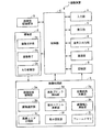
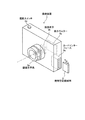
まず、本発明の実施の形態1にかかる撮像装置について説明する。図1は、この実施の形態1にかかる撮像装置の構成を示すブロック図である。また、図2は、この実施の形態1にかかる撮像装置の概要構成を示す斜視図である。図1に示すように、この実施の形態1にかかる撮像装置1は、被写体像を撮像して画像信号を生成する撮像部2と、撮像部2が生成した画像信号を処理する画像処理部3と、各種指示情報が入力される入力部4と、各種情報を表示する表示部5と、音声情報の入出力処理を行う音声入出力部6と、外部装置との間で情報通信を行う通信部7と、各種情報を記憶する記憶部8と、外部装置との間でデータの受け渡しを行うための携帯型記録媒体9と、撮像装置1の全体の処理および動作を制御する制御部Cとを備える。撮像部2、画像処理部3、入力部4、表示部5、音声入出力部6、通信部7、記憶部8および携帯型記録媒体9は、制御部Cに電気的に接続され、制御部Cは、これらの各構成部位を制御する。
(Embodiment 1)
First, the imaging apparatus according to the first embodiment of the present invention will be described. FIG. 1 is a block diagram illustrating a configuration of the imaging apparatus according to the first embodiment. FIG. 2 is a perspective view illustrating a schematic configuration of the imaging apparatus according to the first embodiment. As illustrated in FIG. 1, an imaging apparatus 1 according to the first embodiment includes an
撮像部2は、撮像光学系2a、撮像素子2bおよびA/D変換部2cを備える。撮像光学系2aは、任意の被写体からの光を集光し、撮像素子2b上に被写体像を結像する。撮像手段としての撮像素子2bは、CCD、CMOS等の個体撮像素子を用いて実現され、撮像光学系2aが集光した光を光信号として検出して被写体像に対応した画像を撮像し、撮像した画像をアナログ信号である電気信号に変換して出力する。A/D変換部2cは、撮像素子2bが出力したアナログ信号をデジタル信号に変換し、画像処理部3に出力する。撮像光学系2aは、焦点距離が可変なズームレンズで実現され、たとえば図2に示すように、複数のレンズを組み合わせて構成される。また、撮像光学系2aは、制御部Cの制御のもと、不図示の駆動装置により一部または全部のレンズが光軸方向に移動されることによって、焦点距離を変更するとともに撮像する画像のピント合わせを行う。なお、撮像光学系2aは、焦点距離が固定された単焦点レンズであってもよく、また、筐体に対して着脱可能に取り付けられ、他の撮像光学系と交換可能に構成してもよい。
The
画像処理部3は、撮像部2から取得した画像信号に対する種々の画像処理の制御を行う画像処理制御部3aと、撮像部2から取得した画像信号の中から、画像のブレを補正する対象となる対象画像およびこの補正の基準となる基準画像を選択する画像選択部3bと、選択された対象画像を複数の画素エリアに分割する画素エリア分割部3cと、この分割された各画素エリアの境界を含まないとともに各画素エリアからはみ出さない少なくとも2つの対象画素ブロックを対象画像から抽出する画素ブロック抽出部3dと、この抽出された各対象画素ブロックの位置に対応する基準画像上の位置からこの各対象画素ブロックの位置までの移動量を示す動きベクトルを演算する動きベクトル演算部3eと、この演算された各動きベクトルの対象画像のブレに対する信頼度をもとに抽出した各対象画素ブロックの重みを示す重み付け係数を設定する重み設定部3fと、所定の座標原点を基準とした各対象画素ブロックの位置ベクトル、動きベクトル演算部3eによって演算された各動きベクトルおよび重み設定部3fによって設定された各重み付け係数をもとに、対象画像をアフィン変換するための変換係数を演算する変換係数演算部3gと、この演算結果をもとに対象画像をアフィン変換してこの対象画像のブレを補正する画像補正演算部3hと、画像情報を一時的に記憶するフレームメモリ3iとを備える。画像処理部3が備えるこれらの各構成部位は、制御部Cからの指示に基づいた画像処理制御部3aからの指示にしたがって画像信号を処理し、処理結果である画像情報、ブレ補正情報、演算結果等を適宜に制御部Cまたは記憶部8に出力する。また、画像処理部3は、取得した画像信号に対し、γ補正、Y/C分離(輝度信号/色信号分離)、色変換等の各種画像処理を行うようにしてもよい。
The
入力部4は、撮像装置1が行う各種処理および動作の指示情報の入力を外部から受け付けるとともに、入力された指示情報を制御部Cに出力する。入力部4が受け付ける指示情報には、撮像装置1の起動/終了、撮影の開始/終了、撮像光学系2aのピント合わせおよびズームポジションの設定、撮像モードの設定、撮像した画像信号の処理方法の設定等が含まれる。入力部4は、ボタン型、トグル型等の各種スイッチ、入力キー、タッチパネルなどによって実現され、たとえば、図2に示すように、撮影の開始/終了を指示する撮影スイッチ4aが配置される。
The input unit 4 receives input of instruction information for various processes and operations performed by the imaging apparatus 1 from the outside, and outputs the input instruction information to the control unit C. The instruction information received by the input unit 4 includes start / end of the image pickup apparatus 1, start / end of shooting, focusing and zoom position setting of the image pickup
表示部5は、たとえば、液晶ディスプレイ、有機EL(Electroluminescence)ディスプレイ、LED等を用いた表示装置を備え、制御部Cからの指示に基づいて各種情報を表示する。表示部4が表示する情報には、撮像部2が撮像して生成した画像情報、画像処理部3が処理した画像情報、制御部Cが制御する各種処理および動作の開始や完了を報知する報知情報、各種処理および動作で発生したエラーを報知するエラー情報等がある。表示部5は、たとえば、図2に示すように、撮像装置1の背面部に液晶ディスプレイで実現した表示モニター5aを備え、撮像装置1が撮像する画像をほぼリアルタイムで表示する。さらに、表示モニター5aは、記憶部8に記憶された画像等、各種情報を表示するようにしてもよい。
The
音声入出力部6は、マイクロフォンおよびスピーカーを用いて実現され、外部から音声情報の入力を受け付け、入力された音声情報を制御部Cに出力するとともに、制御部Cから入力された音声情報を外部に出力する。音声入出力部6が入出力を行う情報には、撮像部2が撮影した映像に対応する音声情報等がある。なお、音声入出力部6は、各構成部位が行う処理の開始や完了を報知する所定の報知音の出力、あるいは各種処理および動作で発生したエラーを報知する所定の警告音の出力を行うようにしてもよい。
The voice input /
通信部7は、RS232C、USB、IEEE1394等の外部通信用インターフェース、あるいはIrDA規格に準拠した赤外線通信インターフェース等を用いて実現され、制御部Cからの指示に基づいて外部装置との間で画像情報、音声情報等の各種情報通信を行う。
The
記憶部8は、所定のOSを起動するプログラム、処理プログラム等の各種情報が予め記憶されたROMと、各処理の各種処理パラメータ、各構成部位に入出力される各種情報等を記憶するRAMとを用いて実現される。記憶部8が記憶する情報には、撮像部2が撮像した画像情報、画像処理部3の処理結果である画像情報、補正情報、演算結果等、画像処理部3で用いる演算パラメータ、撮像部2が撮影した映像に対応する音声情報、撮像装置1の各種設定情報等がある。
The
携帯型記録媒体9は、不揮発性メモリであるスマートメディア(登録商標)等のフラッシュメモリ、DVD(DigitalVersatileDisk)等の光記憶媒体等が用いられ、たとえば図2に示すように、カードインターフェース9aを介して撮像装置1に着脱可能に接続され、撮像装置1に挿着された場合、画像データ等の各種情報の出力または記録が可能となる。携帯型記録媒体9は、制御部Cからの指示に基づいて情報の出力および記録を行う。
As the
制御部Cは、記憶部8が記憶する処理プログラムを実行するCPU等によって実現され、撮像装置1の各構成部位を制御する。特に、制御部Cは、画像処理制御部3aに画像を処理してブレを補正させ、補正した画像情報を表示部5に表示させるとともに、記憶部8に記憶させる。また、制御部Cは、撮像部2が撮像した画像情報を通信部7によって外部に出力するか、あるいは携帯型記録媒体9に記録する。なお、制御部Cは、画像処理部3の処理結果である画像情報を外部に出力するようにしてもよい。
The control unit C is realized by a CPU or the like that executes a processing program stored in the
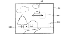
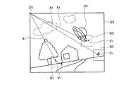
つぎに、画像処理部3が行う画像のブレの補正処理について説明する。図3−1および図3−2は、撮像装置1によって撮像した動画像の一部の画像であり、それぞれ画像のブレを補正する基準となる基準画像およびブレを補正する対象となる対象画像の一例を示す図である。図3−1および図3−2に示すように、対象画像G1は、基準画像G0に対し、撮影時の撮像装置1の動きに対応した画像のブレを生じている。このような画像のブレは、一般にアフィン変換によって表現することが可能であり、逆に、対象画像G1をアフィン変換することによって画像のブレを補正することができる。ここで、アフィン変換とは、回転変換等の線形変換と、平行移動であるシフト変換との組み合わせによる図形等の変換であり、一般に次式(1)によって表わされる。
X’=T・X+S ・・・(1)
ここで、アフィン変換前後の図形の対応する任意の点を示す位置ベクトルをそれぞれXおよびX’とし、アフィン変換の線形変換部分を示す変換係数であるマトリックスをTとし、アフィン変換のシフト変換部分を示す変換係数であるベクトルをSとしている。ただし、図3−2に示すようにシフトおよび回転からなる画像のブレの場合、線形変換を示すマトリックスTは、回転角がφである反時計回りの回転変換を示す回転マトリックスR(φ)に置き換えることができる。なお、対象画像G1および基準画像G0の一部の被写体は、基準画像G0中の被写体像U0と対象画像G1中の被写体像U1の関係に示すように、画像のブレとは別に位置および姿勢を変化させており、この変化は、アフィン変換によって補正されない。
Next, image blur correction processing performed by the
X ′ = T · X + S (1)
Here, the position vectors indicating the corresponding arbitrary points of the figure before and after the affine transformation are X and X ′, respectively, the matrix that is the transformation coefficient indicating the linear transformation part of the affine transformation is T, and the shift transformation part of the affine transformation is The vector which is the conversion coefficient shown is S. However, as shown in FIG. 3-2, in the case of image blur consisting of shift and rotation, the matrix T indicating the linear conversion is a rotation matrix R (φ) indicating the counterclockwise rotation conversion whose rotation angle is φ. Can be replaced. Note that some of the subjects in the target image G1 and the reference image G0 have positions and orientations apart from image blurring, as shown in the relationship between the subject image U0 in the reference image G0 and the subject image U1 in the target image G1. This change is not corrected by the affine transformation.
画像処理部3は、たとえば、図3−2に示すように、対象画像G1から対象画素ブロックB1〜B3を抽出し、抽出した各対象画素ブロックB1〜B3の動きベクトルV1〜V3をブロックマッチング処理によって演算する。そして、画像処理部3は、演算した動きベクトルV1〜V3と、動きベクトルV1〜V3の画像のブレに対する信頼度をもとに設定した各対象画素ブロックB1〜B3の重み付け係数w1〜w3と、各対象画素ブロックB1〜B3の中心位置を指す位置ベクトルX1〜X3とをもとに、対象画像G1のブレに対応するアフィン変換の変換係数を演算し、演算した変換係数をもとに対象画像G1をアフィン変換して画像のブレを補正する。ここで、ブロックマッチング処理とは、抽出した各対象画素ブロックB1〜B3の基準画像G0からの平行移動量を求める処理であり、具体的には、対象画素ブロックB1〜B3のそれぞれに最も一致する画素ブロックB01,B02,B03を基準画像G0上で検出し、検出した各画素ブロックB01,B02,B03の中心位置から、それぞれ対応する対象画素ブロックB1〜B3の中心位置までの移動量を示す動きベクトルV1〜V3を求める処理である。一般に、画素ブロック間の一致度は、画素ブロック内の画素の差分諧調値の絶対値の和、平均諧調値の差の絶対値、諧調値の標準偏差の差の絶対値、諧調値の相互相関関数、諧調値のフーリエ係数等を用いて評価することができる。なお、位置ベクトルX1〜X3を示す基準となる座標原点は、図3−2では対象画像G1の左上角部の点O1としているが、これに限らず、対象画像G1の内部および外部の任意の点でよい。
The
また、画像処理部3は、最小二乗法によって、対象画像G1を補正するためのアフィン変換の変換係数を演算する。すなわち、画像処理部3は、次式(2)に示す評価関数Fの値が最小となるように、アフィン変換の線形変換成分の変換係数である回転マトリックスR(φ)およびシフト変換成分の変換係数であるシフトベクトルSを演算する。
Further, the
評価関数Fの値が最小となる場合、回転マトリックスR(φ)およびシフトベクトルSは、次式(3)および式(4)を満足し、それぞれ式(5)および式(6)によって演算される。 When the value of the evaluation function F is minimized, the rotation matrix R (φ) and the shift vector S satisfy the following expressions (3) and (4) and are calculated by the expressions (5) and (6), respectively. The
Xc=(w1・X1+w2・X2+・・・+wn・Xn)/w ・・・(7)
Vc=(w1・V1+w2・V2+・・・+wn・Vn)/w ・・・(8)
また、回転マトリックスR(φ)は、次式(9)によって表わされる。
X c = (w 1 · X 1 + w 2 · X 2 +... + W n · X n ) / w (7)
V c = (w 1 · V 1 + w 2 · V 2 +... + W n · V n ) / w (8)
The rotation matrix R (φ) is expressed by the following equation (9).
なお、あらかじめ回転角φが小さいとわかっている場合、あるいは各動きベクトルViの大きさが所定値よりも小さい場合などには、式(6)を近似した次式(10)によって回転角φを演算するようにしてもよい。これによって、画像処理部3は、回転マトリックスR(φ)を求める演算処理を高速化することができる。
When it is known in advance that the rotation angle φ is small, or when the magnitude of each motion vector V i is smaller than a predetermined value, the rotation angle φ is obtained by the following equation (10) approximating equation (6). May be calculated. As a result, the
このようにして求められた回転マトリックスR(φ)およびシフトベクトルSによって、画像処理部3は、対象画像G1を次式(11)に示すようにアフィン変換して画像のブレを補正する。
X’=R(φ)・X+{Xc−Vc−R(φ)・Xc} ・・・(11)
このアフィン変換では、画像処理部3は、座標原点O1を中心に対象画像G1を反時計周りに回転角φだけ回転し、この回転した対象画像G1をシフトベクトルS=Xc−Vc−R(φ)・Xcによってシフトする。
Based on the rotation matrix R (φ) and the shift vector S thus obtained, the
X ′ = R (φ) · X + {X c −V c −R (φ) · X c } (11)
In this affine transformation, the
なお、式(11)は、次式(12)に示すように変形することができる。
X’=(R(φ)・(X−Xc)+Xc)−Vc ・・・(12)
すなわち、式(11)に示したアフィン変換は、式(12)に示すように、位置重心ベクトルXcが示す各位置ベクトルXiの重み付き重心を中心に対象画像G1を反時計回りに回転角φだけ回転し、この回転した対象画像G1をベクトル(−Vc)によってシフトする変換に置き換えることができる。この場合、式(11)に示したアフィン変換の演算に比して、画像処理部3が行う演算を簡易にすることができ、画像処理部3の処理負荷を軽減して処理速度を向上させることができる。
Equation (11) can be modified as shown in the following equation (12).
X ′ = (R (φ) · (X−X c ) + X c ) −V c (12)
That is, the affine transformation shown in Expression (11) rotates the target image G1 counterclockwise around the weighted centroid of each position vector X i indicated by the position centroid vector X c as shown in Expression (12). It is possible to replace the rotation of the target image G1 rotated by an angle φ with a vector (−V c ). In this case, the calculation performed by the
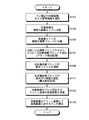
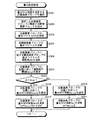
ここで、画像処理部3が行う画像のブレの補正処理手順について、図4を参照して説明する。図4は、画像処理制御部3aが制御する画像のブレの補正処理手順を示すフローチャートである。なお、図4に示すフローチャートは、1つの対象画像に対するブレ補正の処理手順を例示しており、たとえば、動画像のブレを補正する場合、この処理手順を連続して繰り返すようにすればよい。
Here, an image blur correction processing procedure performed by the
図4に示すように、画像処理制御部3aの制御のもと、画像選択部3bは、撮像部2から取得した画像情報の中からブレ補正の対象画像Gtおよび基準画像Goを選択し(ステップS101)、画素エリア分割部3cは、選択した対象画像Gtを複数の画素エリアAs(s=1,2,・・・,h;hは分割数)に分割し(ステップS103)、画素ブロック抽出部3dは、分割した各画素エリアAsをさらに複数の画素ブロックに分割するとともに(ステップS105)、分割した全画素ブロックの中から少なくとも2つの画素ブロックを対象画素ブロックBiとして抽出するブロック抽出処理を行う(ステップS107)。そして、動きベクトル演算部3eは、ブロックマッチング処理によって、各対象画素ブロックBiの動きベクトルViを演算し(ステップS109)、重み設定部3fは、演算した各動きベクトルViの画像のブレに対する信頼度をもとに、各対象画素ブロックBiの重み付け係数wiを設定する重み設定処理を行う(ステップS111)。その後、変換係数演算部3gは、対象画像Gtを補正するためのアフィン変換の変換係数を演算し(ステップS113)、画像補正演算部3hは、演算した変換係数をもとに対象画像Gtをアフィン変換して基準画像Goに対するブレを補正し(ステップS115)、一連のブレ補正処理を終了する。
As shown in FIG. 4, under the control of the image
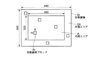
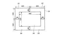
ステップS103では、画素エリア分割部3cは、たとえば図5に示すように、画素エリアAsとして対象画像Gtの中央部にある内側エリアIAと、対象画像Gt内の周辺部にある外側エリアOAとの2つの画素エリアに対象画像Gtを分割する。図5は、具体的に、解像度がVGA(Video Graphics Array)であり640×480画素の対象画像Gtに対し、内側エリアIAを480×320画素とした場合を例示している。なお、画素エリア分割部3cは、さらに多くの領域に対象画像Gtを分割してもよく、たとえば、16×16画素の画素エリア毎に対象画像Gtの全領域を分割するようにしてもよく、この場合、対象画像Gtは、40×30個の画素エリアに分割されることになる。また、対象画像Gtの解像度は、VGAに限らず、XGA(Extended Graphics Array)等、任意の解像度でよい。
In step S103, as shown in FIG. 5, for example, the pixel
ステップS105では、画素ブロック抽出部3dは、8×8画素の画素ブロック毎に対象画像Gt内を分割する。この場合、対象画像Gtは、全体で80×60個の画素ブロックに分割され、そのうち内側エリアIAは、60×40個の画素ブロックに分割される。ここで、8×8画素の画素ブロックは、一般に動画像の圧縮符号化処理中に行われるフレーム間予測処理の処理対象とされる画素ブロックとサイズおよび形状が等しい。このように異なる処理間で分割する画素ブロックの共通化をはかることによって、たとえば、フレーム間予測処理中に演算された各画素ブロックの動きベクトルをこの実施の形態1のブレ補正処理に用いることができ、処理全体の簡易化および処理速度の高速化を促進させることができる。なお、画素エリア分割部3cは、画素ブロック抽出部3dが分割する8×8画素の画素ブロックの大きさを考慮して、縦横がこの画素ブロックの整数倍の大きさである画素エリアAsに分割するようにしている。
In step S105, the pixel
ステップS107では、画素ブロック抽出部3dは、たとえば図5に示すように、各画素エリアIA,OAから複数の対象画素ブロックBiを抽出する。そして、ステップS111では、重み設定部3fは、対象画素ブロックBiが含まれる画素エリアAsに応じて、各対象画素ブロックBiに重み付け係数wiを設定する。この際、重み設定部3fは、対象画像Gtの中央部に近い位置にある対象画素ブロックBiに比して、対象画像Gt内の周辺部に位置する対象画素ブロックBiに対する重み付け係数wiを大きく設定する。すなわち、図5に示した複数の対象画素ブロックBiに対し、重み設定部3fは、内側エリアIA内に位置する画素ブロックBiの重み付け係数wiよりも外側エリアOA内に位置する対象画素ブロックBiの重み付け係数wiを大きく設定する。
In step S107, the pixel
通常、回転をともなう画像のブレは、対象画像Gt内の周辺部で大きなブレを生じるため、外側エリアOA内に位置する対象画素ブロックBiの動きベクトルViは大きなベクトルとなり、高い精度で演算することができる。一方、対象画像Gtの中央部の回転によるブレは小さく、内側エリアIA内に位置する対象画素ブロックBiの動きベクトルViは小さくなる。また、対象画像Gtの中央部では、一般に被写体像が集中することが多く、画像のブレと異なる被写体の動きによって動きベクトルViが変化しやすいため、内側エリアIA内に位置する対象画素ブロックBiの動きベクトルViの演算精度は低くなる。このため、対象画像Gtのブレに対する動きベクトルViの信頼度は、外側エリアOAで高く、内側エリアIAで低く判断され、この結果、内側エリアIA内に位置する対象画素ブロックBiの重み付け係数wiよりも外側エリアOA内に位置する対象画素ブロックBiの重み付け係数wiが大きく設定される。 Normally, image blur with rotation causes large blurring in the periphery of the target image Gt, so that the motion vector V i of the target pixel block Bi located in the outer area OA becomes a large vector and is calculated with high accuracy. be able to. On the other hand, the blur due to the rotation of the central portion of the target image Gt is small, and the motion vector V i of the target pixel block Bi located in the inner area IA is small. In addition, in the central portion of the target image Gt, the subject image is generally concentrated, and the motion vector V i is likely to change due to the movement of the subject that is different from the blur of the image, so the target pixel block Bi located in the inner area IA. The calculation accuracy of the motion vector V i becomes low. For this reason, the reliability of the motion vector V i against blurring of the target image Gt is determined to be high in the outer area OA and low in the inner area IA. As a result, the weighting coefficient w of the target pixel block Bi located in the inner area IA. i weighting coefficients w i of the target pixel block Bi which is located outside area OA is set larger than the.
このように重み設定部3fが、画素エリアAsに応じて各対象画素ブロックBiの重み付け係数wiを設定することにより、この実施の形態1にかかる撮像装置1では、画像のブレと関係ない被写体の動きの影響を軽減することができ、アフィン変換の変換係数である回転マトリックスR(φ)およびシフトベクトルSを高精度に演算して画像のブレを正確に補正することができる。なお、重み設定部3fは、同じ画素エリアAs内に位置する複数の対象画素ブロックBiに対し、さらに各対象画素ブロックBiの位置に応じて画像のブレに対する信頼度を判断し、各重み付け係数wiを設定するようにしてもよい。これによって、変換係数3gは、一層厳密に回転マトリックスR(φ)およびシフトベクトルSを演算することができるようになる。
As described above, the
なお、画素ブロック抽出部3dが分割する画素ブロックは、8×8画素の画素ブロックに限らず、16×16画素等、任意サイズの画素ブロックでよい。また、画素ブロック抽出部3dが抽出する対象画素ブロックBiは、各画素エリアAsからはみ出さなければよく、画素エリアAsの1つであってもよい。さらに、対象画素ブロックBiは、個々に異なるサイズおよび形状であってもよい。なお、画素ブロック抽出部3dは、必ずしもすべての画素エリアAsから対象画素ブロックBiを抽出する必要はなく、たとえば、1つの画素エリアAsだけから抽出するようにしてもよい。
The pixel block divided by the pixel
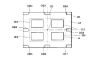
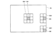
ここで、画素ブロック抽出部3dが抽出する対象画素ブロックBiの他の一例を図6に示す。図6に示すように、画素ブロック抽出部3dは、対象画素ブロックBiとして、内側エリアIAから比較的大きな対象画素ブロックIB1〜IB4を抽出し、外側エリアOAから比較的小さな対象画素ブロックOB1〜OB8を抽出する。これは、重み設定部3fが、内側エリアIA内に位置する対象画素ブロックBiの重み付け係数wiよりも外側エリアOA内に位置する対象画素ブロックBiの重み付け係数wiを大きく設定したのと同様の理由による。すなわち、対象画素ブロックOB1〜OB8の動きベクトルは大きなベクトルとなるため、対象画素ブロックOB1〜OB8のサイズを小さくしても高い精度で動きベクトルを演算することができ、このサイズを小さくすることによって演算の処理負荷を軽減し、処理速度を向上させることができる。一方、対象画素ブロックIB1〜IB4の動きベクトルの演算精度は低いため、大きな領域によって平均化した動きベクトルを演算できるように、抽出する対象画素ブロックIB1〜IB4のサイズを大きくしている。
Here, another example of the target pixel block Bi extracted by the pixel
なお、対象画素ブロックIB1〜IB4およびOB1〜OB8は、対象画像Gtの中心点O2を通る縦横の中心線に対し、各画素エリアIA,OA内で互いに対称に位置するように抽出されている。このように、対象画素ブロックを対称的に抽出することによって、たとえば、重み設定部3fが同じ画素エリアAs内にある対象画素ブロックBiに対して均等に重み付け係数wiを設定した場合、位置重心ベクトルXcで示される各位置ベクトルXiの重み付き重心を中心点O2と一致させることができる。この場合、さらに対象画像Gtに対する座標原点を中心点O2に設定することによって、位置重心ベクトルXcをゼロベクトルにすることができ、式(12)に示すアフィン変換の演算を次式(13)に示すように簡略化することができ、これによって画像処理部3の処理負荷を一層軽減し、処理速度をさらに向上させることができる。
X’=R(φ)・X−Vc ・・・(13)
The target pixel blocks IB 1 to IB 4 and OB 1 to OB 8 are extracted so as to be positioned symmetrically with respect to each other in the pixel areas IA and OA with respect to the vertical and horizontal center lines passing through the center point O2 of the target image Gt. Has been. Thus, by extracting the target pixel block symmetrically, for example, when the
X ′ = R (φ) · X−V c (13)
また、内側エリアIA、外側エリアOA、対象画素ブロックIB1〜IB4および対象画素ブロックOB1〜OB8は、いずれも図6に示したように矩形の領域としたが、任意形状でよい。さらに、画像エリアAsおよび対象画素ブロックBiは、あらかじめ設定された所定の領域であってもよく、対象画像Gtに応じて任意に抽出するようにしてもよく、あるいは対象画像Gtの種々の特性値に応じて抽出するようにしてもよい。 Further, the inner area IA, the outer area OA, the target pixel blocks IB 1 to IB 4 and the target pixel blocks OB 1 to OB 8 are all rectangular areas as shown in FIG. Furthermore, the image area As and the target pixel block Bi may be a predetermined region set in advance, or may be arbitrarily extracted according to the target image Gt, or various characteristic values of the target image Gt. You may make it extract according to.
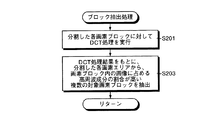
ここで、画素ブロック抽出部3dが、対象画像Gtの特性値に応じて対象画素ブロックBiを抽出する処理の一例について説明する。図7は、図4に示したステップS107のブロック抽出処理をサブルーチン化した処理手順を示すフローチャートである。図7に示すように、このブロック抽出処理では、画素ブロック抽出部3dは、画像処理制御部3aの制御のもと、ステップS105によって分割した各画素ブロックに対してDCT(Discrete Cosine Transform;離散コサイン変換)処理を行い(ステップS201)、このDCT処理結果をもとに、ステップS103によって分割した各画素エリアAsから、画素ブロック内の画像に占める高周波成分の割合が高い複数の画素ブロックを対象画素ブロックBiとして抽出し(ステップS203)、ステップS107へリターンする。ステップS203では、画素ブロック抽出部3dは、DCT処理結果であるDCT係数をDuv(u,v=0,1,・・・,7)として、次式(14)で定める評価値Cr(r=1,2,・・・,h)を用い、評価値Crが大きいほど画素ブロック内の画像に占める高周波成分の割合が高いものと判断する。
Here, an example of processing in which the pixel
このように、画像に占める高周波成分の割合が高い対象画素ブロックBiを抽出することによって、ブロックマッチング処理での処理感度が高い対象画素ブロックBiを抽出することができ、抽出した各対象画素ブロックBiの動きベクトルViを高精度に演算することができるようになるとともに、高精度に回転マトリックスR(φ)およびシフトベクトルSを演算できるようになる。なお、ステップS201によるDCT処理は、必ずしも分割したすべての画素ブロックに対して行う必要はなく、たとえば、各画素エリアAs内で評価値Crが所定値以上である画素ブロックが8ブロック抽出された時点で処理を終了するようにしてもよい。また、このような場合、対象画像Gtから一様に対象画素ブロックBiを抽出するように、たとえば図8に示すように、対象画像Gt内を中央部および4隅部の5つの画素エリアA1〜A5に分割するとよい。なお、図8に示した各画素エリアA1〜A5のサイズを示す数値は、解像度をVGAとした対象画像Gtに対して画素エリアA1〜A5を設定した一例であり、各画素エリアA1〜A5の大きさはこれに限定されるものではない。 As described above, by extracting the target pixel block Bi having a high ratio of the high-frequency component in the image, it is possible to extract the target pixel block Bi having high processing sensitivity in the block matching process, and each extracted target pixel block Bi. together comprising a motion vector V i to be able to calculate with high precision, it becomes possible to calculates the rotation matrix R (phi) and the shift vector S with high accuracy. Note that the DCT process in step S201 does not necessarily have to be performed on all divided pixel blocks. For example, eight pixel blocks having an evaluation value Cr greater than or equal to a predetermined value in each pixel area As are extracted. You may make it complete | finish a process at the time. Further, in such a case, the target pixel block Bi is extracted from the target image Gt uniformly, for example, as shown in FIG. It is good to divide into A5. The numerical values indicating the sizes of the pixel areas A1 to A5 shown in FIG. 8 are an example in which the pixel areas A1 to A5 are set for the target image Gt with the resolution VGA. The size is not limited to this.
つぎに、ステップS111に示した重み設定処理の変形例について説明する。上述した重み設定処理では、各対象画素ブロックBiが含まれる画素エリアAsに応じて、各対象画素ブロックBiの重み付け係数wiを設定するようにしていたが、各対象画素ブロックBiの動きベクトルViの大きさに応じて重み付け係数wiを設定するようにしてもよい。この場合、重み設定部3fは、たとえば、各対象画素ブロックBiの重み付け係数wiをwi=Vi・Vi=|Vi|2によって求めるようにすればよい。このような重み設定処理は、動きベクトルViが大きいほど画像のブレに対する動きベクトルViの信頼度が高いと判断する処理であり、たとえば、木の葉の揺らぎなど細かな動きが多い被写体を撮像した対象画像Gtのブレを補正する場合に有効である。この場合、被写体の動きと同程度に動きベクトルViが小さい対象画素ブロックBiの重み付け係数wiを小さくすることができ、被写体の動きに起因した演算誤差を低減させることができる。
Next, a modification of the weight setting process shown in step S111 will be described. In the weight setting process described above, the weighting coefficient w i of each target pixel block Bi is set according to the pixel area As including each target pixel block Bi, but the motion vector V of each target pixel block Bi is set. The weighting coefficient w i may be set according to the size of i . In this case, for example, the
なお、各対象画素ブロックBiが含まれる画素エリアAsと、各対象画素ブロックBiの動きベクトルViの大きさとの両方に対応し、たとえば次式(15)によって、重み付け係数wiを設定するようにしてもよい。
wi=warea+(Vi・Vi)/k2 ・・・(15)
ただし、画素エリアAsに応じた重み付け係数をwareaとし、動きベクトルViの大きさを規格化する係数をkとしている。係数kは、動きベクトルViの大きさの最大値を画素数単位で想定した数値である。たとえば、動きの激しいスポーツ等を撮影する場合、動きベクトルViの大きさが大きくなる可能性が高いので係数kの値を大きく設定し、風景等を撮影する場合、動きベクトルViの大きさが大きくなる可能性が低いので係数kの値を小さく設定するようにすればよく、被写体に応じて適宜変更できるようにするとよい。
It should be noted that the weighting coefficient w i is set by the following equation (15), for example, corresponding to both the pixel area As including each target pixel block Bi and the magnitude of the motion vector V i of each target pixel block Bi. It may be.
w i = w area + (V i · V i ) / k 2 (15)
However, the weighting coefficient corresponding to the pixel area As is w area and the coefficient for normalizing the magnitude of the motion vector V i is k. The coefficient k is a numerical value assuming the maximum value of the motion vector V i in units of the number of pixels. For example, when shooting a sport or the like where the motion is intense, there is a high possibility that the size of the motion vector V i is large. Therefore, when the value of the coefficient k is set large and a landscape or the like is shot, the size of the motion vector V i Therefore, the value of the coefficient k may be set small, and may be changed as appropriate according to the subject.
また、ステップS111に示した重み設定処理の別の変形例として、対象画素ブロックBiの動きベクトルViと、対象画素ブロックBiに隣接する各隣接画素ブロックBij(j=1,2,・・・,m)の動きベクトルVij(j=1,2,・・・,m)とをもとに、動きベクトルViに対する動きベクトルVijのばらつき程度を示す発散度diを演算し、この発散度diに応じて重み付け係数wiを設定するようにしてもよい。ここで、発散度diは、次式(16)によって演算される特性値である。 As another modification of the weight setting process shown in step S111, the motion vector V i of the target pixel block Bi and each adjacent pixel block Bij adjacent to the target pixel block Bi (j = 1, 2,... , motion vector V ij (j = 1,2 of m), · · ·, m) and based on, I calculate the divergence d i indicating the degree of dispersion of the motion vector V ij for the motion vector V i, this The weighting coefficient w i may be set according to the divergence degree d i . Here, the divergence degree d i is a characteristic value calculated by the following equation (16).
この発散度diに応じて重み付け係数wiを設定する重み設定処理では、重み設定部3fは、発散度diが小さいほど重み付け係数wiを大きく設定する。すなわち、重み設定部3fは、対象画素ブロックBiおよびこの周囲近傍の領域の移動方向の統一性が高く、発散度diが小さいほど、画像のブレに対する動きベクトルViの信頼度が高いと判断する。このような重み設定処理を用いると、被写体の動きや画像信号のノイズ等に起因する局所的な動きベクトルViの演算誤差の影響を軽減することができ、回転マトリックスR(φ)およびシフトベクトルSを高精度に演算して画像のブレを正確に補正することができる。
In the weight setting process for setting the weighting coefficient w i according to the divergence degree d i , the
ここで、発散度diに応じて重み付け係数wiを設定する重み設定処理の処理手順の一例を説明する。図9は、図4に示したステップS111の重み設定処理をサブルーチン化した処理手順を示すフローチャートである。図9に示すように、画像処理制御部3aの制御のもと、重み設定部3fは、重み付け係数wiを設定する対象画素ブロックBiを選択し(ステップS301)、選択した対象画素ブロックBiに隣接する隣接画素ブロックBijを抽出する(ステップS303)。そして、重み設定部3fは、ステップ109で演算された対象画素ブロックBiの動きベクトルViを取得し(ステップS305)、各隣接画素ブロックBijの動きベクトルVijを演算し(ステップS307)、対象画素ブロックBiに対する隣接画素ブロックBijの発散度diを式(16)によって演算する(ステップS309)。その後、重み設定部3fは、対象画素ブロックBiの位置に応じて発散度diの閾値dmaxを設定し(ステップS311)、発散度diと閾値dmaxの大きさを比較して(ステップS313)、発散度diが閾値dmaxよりも小さい場合(ステップS313:Yes)、対象画素ブロックBiの位置に対応した重み付け係数wareaを設定し(ステップS315)、対象画素ブロックBiの重み付け係数wiを式(15)によって演算して(ステップS317)、ステップS111にリターンする。一方、発散度diが閾値dmaxよりも小さくない場合(ステップS313:No)、重み設定部3fは、対象画素ブロックBiの位置に対応した重み付け係数wareaを設定し(ステップS319)、対象画素ブロックBiの重み付け係数wiをwi=warea/2によって演算して(ステップS321)、ステップS111にリターンする。
Here, an example of a processing procedure of a weight setting process for setting the weighting coefficient w i according to the divergence degree d i will be described. FIG. 9 is a flowchart showing a processing procedure in which the weight setting processing in step S111 shown in FIG. As shown in FIG. 9, under the control of the image
ステップS303では、重み設定部3fは、たとえば図10に示すように、隣接画素ブロックBijを抽出する。すなわち、対象画素ブロックBiとしての対象画素ブロックB4,B5,B6に対し、対象画像Gtの外周エッジに隣接しない対象画素ブロックB4では、対象画素ブロックB4と同じ大きさの周囲8個の隣接画素ブロックB41〜B48を抽出し、対象画素ブロックのエッジに隣接する対象画素ブロックB5では、周囲5個の隣接画素ブロックB51〜B55を抽出し、対象画像Gtのコーナーに位置する対象画素ブロックB6では、周囲3個の隣接画素ブロックB61〜B63を抽出する。なお、重み設定部3fは、隣接画素ブロックBijを抽出する代わりに、対象画素ブロックBiに隣接しないが周囲近傍にある画素ブロックを近傍画素ブロックとして抽出するようにしてもよい。また、画像処理制御部3aは、画素ブロック抽出部3dに隣接画素ブロックBijを抽出させ、重み設定部3fは、この抽出結果を取得するようにしてもよい。
In step S303, the
ステップS311では、重み設定部3fは、ステップS303で抽出した隣接画素ブロックBijの個数mに応じて閾値dmaxを設定し、たとえば、閾値dmaxをdmax=m・322によって設定する。具体的に、図10に示した対象画素ブロックB4,B5,B6に対しては、それぞれ閾値dmaxをdmax=8・322,5・322,3・322に設定する。なお、閾値dmaxの設定方法は、これに限定されず、隣接画素ブロックBijの個数mに対応した他の条件式によって設定してもよく、個数m等の隣接画素ブロックBijの情報を用いずに設定してもよい。また、対象画像の撮像条件等に応じて、閾値dmaxの設定条件を適宜変更できるようにしてもよい。
In step S311, the
なお、ステップS313では、重み設定部3fは、発散度diと閾値dmaxとの関係に応じて、さらに多くの分岐条件を判断するようにしてもよい。また、ステップS317,S321で用いる重み付け係数wiの演算式は、上述した演算式に限定されず、他の演算式を用いてもよい。さらに、ステップS307では、画像処理制御部3aは、動きベクトル演算部3eに動きベクトルVijを演算させ、重み設定部3fは、この演算結果を取得するようにしてもよい。
In step S313, the
また、ステップS111に示した重み設定処理の他の変形例として、対象画素ブロックBiの画像コントラストConiに応じて重み付け係数wiを設定するようにしてもよい。ここで、画像コントラストConiは、種々の方法によって演算し、評価され得るが、たとえば、重み設定部3fは、次式(17)によって画像コントラストConiを演算して評価するようにしてもよい。
As another modification of the weight setting process shown in step S111, the weighting coefficient w i may be set according to the image contrast Con i of the target pixel block Bi. Here, the image contrast Con i can be calculated and evaluated by various methods. For example, the
また、重み設定部3fは、式(14)に示した評価値CrによってConi=Crとして画像コントラストConiを評価するようにしてもよい。この場合、MPEG4動画圧縮等、一般の動画像の圧縮符号化処理中に行われるDCT処理の結果をDCT係数Duvとして共通に利用することができ、全体処理の簡易化および高速化を促進させることができる。なお、評価値CrのようにDCT係数Duvの高周波成分によって表わした評価値を画像コントラストの評価値として併用する技術は、たとえば、特許文献2に開示されている。
Further, the
さらに、重み設定部3fは、従来の撮像装置が備えるオートフォーカス機構によって処理される画像コントラストを利用して、対象画像Biの画像コントラストConiを評価するようにしてもよい。この場合にも、異なる処理間で評価値を共通に利用することができ、全体処理の簡易化および高速化を促進させることができる。
Furthermore, the
このように画像コントラストConiに応じて重み付け係数wiを設定する重み設定処理では、重み設定部3fは、対象画素ブロックBiの画像コントラストConiが高いほど重み付け係数wiを大きく設定する。すなわち、重み設定部3fは、画像コントラストConiが高いほど画像のブレに対する動きベクトルViの信頼度が高いと判断する。このような重み設定処理を用いると、ブロックマッチング処理での処理感度が高い対象画素ブロックBiほど重み付け係数wiを大きく設定することができ、回転マトリックスR(φ)およびシフトベクトルSを高精度に演算して画像のブレを正確に補正することができる。
Thus, in the weight setting process for setting the weighting coefficient w i according to the image contrast Con i , the
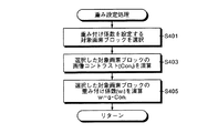
ここで、画像コントラストConiに応じて重み付け係数wiを設定する重み設定処理の処理手順の一例を説明する。図11は、図4に示したステップS111の重み設定処理をサブルーチン化した処理手順を示すフローチャートである。図11に示すように、画像処理制御部3aの制御のもと、重み設定部3fは、重み付け係数wiを設定する対象画素ブロックBiを選択し(ステップS401)、選択した対象画素ブロックBiの画像コントラストConiを演算し(ステップS403)、重み付け係数wiをwi=g・Coniによって演算し(ステップS405)、ステップS111にリターンする。ここで、係数gは、g=1/4程度のゼロより大きな実数値に設定するとよい。ただし、これに限定されず、たとえば、対象画素ブロックBiの諸特性値をもとに係数gを設定するようにしてもよく、係数gを関数値として設定してもよい。
Here, an example of a processing procedure of a weight setting process for setting the weighting coefficient w i according to the image contrast Con i will be described. FIG. 11 is a flowchart showing a processing procedure in which the weight setting processing in step S111 shown in FIG. As shown in FIG. 11, under the control of the image
また、ステップS111に示した重み設定処理の他の変形例として、回転マトリックスR(φ)およびシフトベクトルSの演算精度に対する各対象画素ブロックBiの重要度に応じて、画像のブレに対する動きベクトルViの信頼度を判断し、この信頼度をもとに重み付け係数wiを設定するようにしてもよい。ここで、回転マトリックスR(φ)およびシフトベクトルSの演算精度は、演算に用いる各動きベクトルViの信頼度が等しい場合、対応する各対象画素ブロックBiの相互間隔が大きいほど向上する。このため、相互間隔が大きな対象画素ブロックBiほど演算精度に対する重要度が高く、逆に、この重要度が高い対象画素ブロックBiほど重み付け係数wiを大きく設定することによって、回転マトリックスR(φ)およびシフトベクトルSを高精度に演算して画像のブレを正確に補正することができる。 Further, as another modification of the weight setting process shown in step S111, the motion vector V with respect to the blurring of the image depends on the importance of each target pixel block Bi with respect to the calculation accuracy of the rotation matrix R (φ) and the shift vector S. The reliability of i may be determined, and the weighting coefficient w i may be set based on this reliability. Here, when the reliability of each motion vector V i used in the calculation is equal, the calculation accuracy of the rotation matrix R (φ) and the shift vector S improves as the mutual interval between the corresponding target pixel blocks Bi increases. Therefore, the target pixel block Bi having a larger mutual interval has a higher importance for the calculation accuracy, and conversely, by setting the weighting coefficient w i to be larger for the target pixel block Bi having a higher importance, the rotation matrix R (φ). In addition, the shift vector S can be calculated with high accuracy to correct the image blur accurately.
さらに、ステップS111に示した重み設定処理には、ここに示した設定処理方法に限定されず様々な処理方法を用いることができる。また、個々の設定処理方法を組み合わせて各動きベクトルViの信頼度を判断し、重み付け係数wiを設定するようにしてもよい。 Furthermore, the weight setting processing shown in step S111 is not limited to the setting processing method shown here, and various processing methods can be used. Alternatively, the weighting coefficient w i may be set by determining the reliability of each motion vector V i by combining individual setting processing methods.
以上説明したこの実施の形態1にかかる撮像装置1では、複数の画像の中から対象画像を選択し、選択した対象画像を画素エリアに分割し、分割した画素エリアから複数の対象画素ブロックを抽出し、抽出した対象画素ブロックの種々の特性値をもとに画像のブレに対する動きベクトルの信頼度を判断し、この信頼度をもとに各画素ブロックの重み付け係数を設定して信頼度に応じた動きベクトルの演算処理を行うため、常に高い精度で対象画像のブレに対応するアフィン変換の変換係数を演算することができ、この演算した変換係数をもとに対象画像をアフィン変換して対象画像のブレを正確に補正することができる。また、対象画素ブロックの位置、動きベクトルの大きさ、画像の高周波成分の割合、画像コントラスト、近傍画素ブロックとの関連性を示す動きベクトルの発散度など、対象画素ブロックの種々の特性値をもとに、対象画素ブロックの抽出および動きベクトルの信頼度の判定を行っているため、被写体あるいは被写体像の様々な動きや状態に適応し、常に高精度で確実に画像のブレを検出して補正することができる。 In the imaging apparatus 1 according to the first embodiment described above, a target image is selected from a plurality of images, the selected target image is divided into pixel areas, and a plurality of target pixel blocks are extracted from the divided pixel areas. Then, the reliability of the motion vector against image blur is determined based on the various characteristic values of the extracted target pixel block, and the weighting coefficient of each pixel block is set based on this reliability, depending on the reliability. Since the motion vector calculation process is performed, the conversion coefficient of the affine transformation corresponding to the blurring of the target image can always be calculated with high accuracy, and the target image is affine transformed based on the calculated conversion coefficient. Image blur can be corrected accurately. It also has various characteristic values of the target pixel block such as the position of the target pixel block, the size of the motion vector, the ratio of the high frequency component of the image, the image contrast, and the divergence of the motion vector indicating the relationship with the neighboring pixel block. In addition, since the target pixel block is extracted and the reliability of the motion vector is determined, it can be applied to various movements and states of the subject or subject image, and it can always detect and correct image blurring with high accuracy. can do.
(実施の形態2)
つぎに、本発明の実施の形態2について説明する。上述した実施の形態1では、対象画像を分割した各画素エリアAsから複数の対象画素ブロックBiを抽出し、画像のブレに対応するアフィン変換の変換係数を高精度に演算するようにしていたが、この実施の形態2では、対象画像の4つの隅領域から2つの対象画素ブロックBiを抽出し、簡易かつ高速にアフィン変換の変換係数を演算するようにしている。
(Embodiment 2)
Next, a second embodiment of the present invention will be described. In the first embodiment described above, a plurality of target pixel blocks Bi are extracted from each pixel area As obtained by dividing the target image, and the conversion coefficient of the affine transformation corresponding to the blurring of the image is calculated with high accuracy. In the second embodiment, the two target pixel blocks Bi are extracted from the four corner regions of the target image, and the conversion coefficient of the affine transformation is calculated easily and at high speed.
図12は、対象画像の隅領域から2つの対象画素ブロックを抽出した状態の一例を示す模式図である。図12に示すように、この実施の形態2では、対象画像Gtの4隅の領域のうち、図上で右下および左上の隅領域から、それぞれ対象画素ブロックBiとしての対象画素ブロックBS1,BS2を抽出している。また、抽出した対象画素ブロックBS1の中心点OSをこの対象画像Gtに対する座標原点に設定して、対象画素ブロックBS2を示す位置ベクトルをXS2とし、対象画素ブロックBS1,BS2のそれぞれの動きベクトルをVS1,VS2としている。なお、対象画素ブロックBS1を示す位置ベクトルはゼロベクトルとなる。 FIG. 12 is a schematic diagram illustrating an example of a state in which two target pixel blocks are extracted from a corner area of the target image. As shown in FIG. 12, in the second embodiment, among the four corner regions of the target image Gt, the target pixel blocks BS1 and BS2 as the target pixel block Bi from the lower right and upper left corner regions in the drawing, respectively. Is extracted. Further, the center point OS of the extracted target pixel block BS1 is set as the coordinate origin for the target image Gt, the position vector indicating the target pixel block BS2 is set to X S2, and the respective motion vectors of the target pixel blocks BS1 and BS2 are set. V S1 and V S2 are set. Note that the position vector indicating the target pixel block BS1 is a zero vector.
対象画素ブロックBS1,BS2の重み付け係数をそれぞれwS1,wS2とすると、重み付け係数の総和wはw=wS1+wS2となり、位置重心ベクトルXcは、式(7)によってXc=wS2・XS2/wとなり、動き重心ベクトルVcは、式(8)によってVc=(VS1+wS2・VS2)/wとなる。重み設定処理では、重み設定部3fは、各重み付け係数wS1,wS2の大きさをwS1≒1、wS2≪1とし、それぞれ限りなく「1」および「0」に近づける。この場合、重み付け係数の総和wはw≒1に近似され、位置重心ベクトルXcはゼロベクトルに近似され、動き重心ベクトルVcはVc≒VS1に近似される。これによって、回転マトリックスR(φ)の回転角φおよびシフトベクトルSは、それぞれ式(5)および式(6)を用いた次式(18)および式(19)によって表わされる。
S=VS1 ・・・(18)
Assuming that the weighting coefficients of the target pixel blocks BS1 and BS2 are w S1 and w S2 , respectively, the total sum w of the weighting coefficients is w = w S1 + w S2 , and the position centroid vector X c is expressed by X c = w S2 according to Expression (7) X S2 / w, and the motion centroid vector V c becomes V c = (V S1 + w S2 · V S2 ) / w according to the equation (8). In the weight setting process, the
S = V S1 (18)
このように、この実施の形態2では、対象画像Gtの4隅の領域のうち対角関係にある2つの隅領域から対象画素ブロックBS1,BS2を抽出し、一方の対象画素ブロックBS1の中心位置を座標原点に設定し、対象画素ブロックBS1,BS2の重み付け係数wS1,wS1をそれぞれ限りなく「1」および「0」に近づけることによって、実施の形態1に比して簡易な演算式を用いた回転マトリックスR(φ)およびシフトベクトルSの演算処理を行うことができ、この結果、さらに高速に演算処理を行うことができる。このような高速のブレ補正処理は、たとえば、図2に示した表示モニター5aによって撮像中の動画像を観察する場合など、リアルタイムで連続してブレを補正する必要がある場合に有効である。
As described above, in the second embodiment, the target pixel blocks BS1 and BS2 are extracted from two corner areas having a diagonal relationship among the four corner areas of the target image Gt, and the center position of one target pixel block BS1 is extracted. Is set as the coordinate origin, and the weighting coefficients w S1 and w S1 of the target pixel blocks BS1 and BS2 are each made as close as possible to “1” and “0”, so that a simple arithmetic expression can be obtained as compared with the first embodiment. Calculation processing of the used rotation matrix R (φ) and shift vector S can be performed, and as a result, calculation processing can be performed at higher speed. Such high-speed blur correction processing is effective when it is necessary to continuously correct blur in real time, for example, when a moving image being captured is observed with the
なお、この実施の形態2の重み設定処理では、重み設定部3fは、座標原点に設定した対象画素ブロックBS1を重視して演算処理に対する重要度を高く設定し、この重要度に対応して動きベクトルVS1の信頼度を高く判断した結果として、各重み付け係数wS1,wS1を限りなく「1」および「0」に近づけるようにしている。
In the weight setting process according to the second embodiment, the
また、図12に示した対象画素ブロックBS1,BS2は、対象画像Gt内で対角位置にある右下および左上の隅領域から抽出されているが、対象画素ブロックBiの抽出方法はこれに限定されず、対象画像Gt内の4隅の領域のうち任意の2つの隅領域から各1つの対象画素ブロックBiを抽出するようにすればよい。すなわち、抽出した2つの対象画素ブロックBiは、必ずしも対角位置にある必要はなく、対象画像Gt内で横方向または縦方向に並んだ位置関係にあってもよい。 Further, the target pixel blocks BS1 and BS2 shown in FIG. 12 are extracted from the lower right and upper left corner regions at the diagonal positions in the target image Gt, but the extraction method of the target pixel block Bi is limited to this. Instead, one target pixel block Bi may be extracted from any two corner regions of the four corner regions in the target image Gt. That is, the two extracted target pixel blocks Bi do not necessarily have to be in a diagonal position, and may be in a positional relationship aligned in the horizontal direction or the vertical direction in the target image Gt.
なお、上述した実施の形態1および2では、撮像装置1によって撮像した画像のブレ補正を行うようにしていたが、外部から入力された画像または記憶部8に記憶していた画像のブレ補正を行うようにしてもよい。また、本発明のブレ補正方法を撮像装置1と異なるコンピュータ等の画像処理装置に適用し、この画像処理装置に外部から入力された画像のブレ補正を行うようにしてもよい。この場合、たとえば、撮像装置1によって撮像された画像に対し、表示モニター5aに出力する場合にブレ補正処理を適用し、携帯型記憶媒体9または通信部7を介して外部に出力する場合にはブレ補正処理を適用せず、出力した外部装置である画像処理装置上でブレ補正処理を行うようにしてもよい。この場合、画像処理部3の処理負荷を軽減し、処理を高速化することができる。
In the first and second embodiments described above, blur correction of an image captured by the imaging apparatus 1 is performed. However, blur correction of an image input from the outside or an image stored in the
また、上述した実施の形態1および2の各種ブレ補正処理は、入力部4等から入力されたブレ補正処理のモードの選択情報をもとに、随時選択し切り替えるようにしてもよい。 The various blur correction processes of the first and second embodiments described above may be selected and switched as needed based on the selection information of the blur correction process mode input from the input unit 4 or the like.
1 撮像装置
2 撮像部
2a 撮像光学系
2b 撮像素子
2c A/D変換部
3 画像処理部
3a 画像処理制御部
3b 画像選択部
3c 画素エリア分割部
3d 画素ブロック抽出部
3e 動きベクトル演算部
3f 重み設定部
3g 変換係数演算部
3h 画像補正演算部
3i フレームメモリ
4 入力部
4a 撮影スイッチ
5 表示部
5a 表示モニター
6 音声入出力部
7 通信部
8 記憶部
9 携帯型記録媒体
9a カードインターフェース
A1〜A4 画素エリア
B1〜B6,B01,B02,B03,Bi,BS1,BS2,IB1〜IB4,OB1〜OB8 画素ブロック
G0,G1,Gt 対象画像
O1,O2,Os 座標原点
V1〜V3,VS1,VS2 動きベクトル
X,X1〜X3 位置ベクトル
DESCRIPTION OF SYMBOLS 1 Image pick-up
Claims (14)
前記対象画像から、画像の中央部に近い内寄りに位置する対象画素ブロックと、画像の周辺部に近い外寄りに位置する対象画素ブロックの2つの対象画素ブロックを少なくとも抽出するブロック抽出ステップと、
前記ブロック抽出ステップによって抽出された各対象画素ブロックの位置に対応する前記基準画像上の位置から該各対象画素ブロックの位置までの移動量を示す動きベクトルを演算するベクトル演算ステップと、
前記ベクトル演算ステップによって演算された各動きベクトルの前記画像のブレに対する信頼度をもとに、前記各対象画素ブロックの重み付け係数を設定する重み設定ステップと、
所定の座標原点を基準とした前記各対象画素ブロックの位置ベクトル、前記各動きベクトルおよび前記重み設定ステップによって設定された各重み付け係数をもとに、前記対象画像をアフィン変換するための変換係数を演算する係数演算ステップと、
前記係数演算ステップの演算結果をもとに前記対象画像をアフィン変換して該対象画像のブレを補正する補正演算ステップと、
を有し、
前記重み設定ステップは、
(a)前記各対象画像で内寄りに位置する画素ブロックの重み付け係数よりも前記各対象画像で外寄りに位置する対象画素ブロックの重み付け係数を大きく設定する、
(b)前記各対象画素ブロックの動きベクトルの大きさが大きいほど重み付け係数を大きく設定する、
(c)前記各対象ブロックのうち、前記アフィン変換における前記変換係数の線形変換成分およびシフト成分にそれぞれ対応する回転マトリックスおよびシフトベクトルの演算精度に対する重要度が高いほど重み付け係数を大きく設定する、
の何れかの手順に基づいて前記各対象画素ブロックの重み付け係数を設定することを特徴とするブレ補正方法。 An image selection step of selecting a target image that is a target for correcting image blur and a reference image that is a reference for the correction from a plurality of images captured by the imaging device;
A block extraction step for extracting at least two target pixel blocks from the target image: a target pixel block located on the inner side near the center of the image and a target pixel block located on the outer side near the peripheral part of the image ;
A vector calculation step of calculating a motion vector indicating a movement amount from a position on the reference image corresponding to a position of each target pixel block extracted by the block extraction step to a position of each target pixel block;
A weight setting step for setting a weighting coefficient of each target pixel block based on the reliability of the motion vector calculated by the vector calculation step with respect to blurring of the image;
Based on the position vector of each target pixel block with respect to a predetermined coordinate origin, each motion vector, and each weighting coefficient set by the weight setting step, a conversion coefficient for affine transformation of the target image is obtained. A coefficient calculation step to be calculated;
A correction calculation step of correcting the blur of the target image by affine transforming the target image based on the calculation result of the coefficient calculation step;
Have
The weight setting step includes:
(A) setting a weighting coefficient of a target pixel block positioned outward in each target image to be larger than a weighting coefficient of a pixel block positioned inward in each target image;
(B) The weighting coefficient is set to be larger as the size of the motion vector of each target pixel block is larger.
(C) among the target blocks, the weighting coefficient is set to be larger as the importance of the rotation matrix and the shift vector corresponding to the linear transformation component and the shift component of the transformation coefficient in the affine transformation is higher.
A blur correction method, wherein a weighting coefficient for each target pixel block is set based on any one of the procedures .
前記補正演算ステップは、前記回転マトリックスによって前記位置ベクトルの重み付き重心を中心に前記回転角だけ反時計周りに前記対象画像を回転した後、前記シフトベクトルによって該対象画像をシフトすることを特徴とする請求項2に記載のブレ補正方法。 The coefficient calculating step calculates a shift vector S corresponding to the shift component of the transform coefficient by S = X c −V c ,
In the correction calculation step, the target image is rotated counterclockwise by the rotation angle around the weighted center of gravity of the position vector by the rotation matrix, and then the target image is shifted by the shift vector. The blur correction method according to claim 2 .
前記補正演算ステップは、前記シフトベクトルによって前記対象画像をシフトした後、前記回転マトリックスによって前記座標原点を中心に前記回転角だけ反時計方向に該対象画像を回転することを特徴とする請求項2に記載のブレ補正方法。 In the coefficient calculation step, the rotation matrix that performs rotation conversion counterclockwise by the rotation angle φ is R (φ), and the shift vector S corresponding to the shift component of the conversion coefficient is S = R (−φ) · (X c −V c ) −X c
The correction calculation step, after shifting the target image by the shift vector, claim 2, characterized in that rotating the object image only in a counterclockwise direction the rotation angles about the coordinate origin by the rotation matrix The blur correction method described in 1.
前記係数演算ステップは、前記2つの隅領域から抽出された対象画素ブロックのうち一方の対象画素ブロックの位置を前記座標原点とし、該座標原点に位置する前記対象画素ブロックに対応する前記位置ベクトル、前記動きベクトルおよび前記重み付け係数をそれぞれX1,V1およびw1とし、前記重み設定ステップによって、前記座標原点に位置する対象画素ブロックに対する前記重み付け係数および他方の対象画素ブロックに対する前記重み付け係数がそれぞれ1および0に限りなく近づけられた場合、数式1を近似した数式3によって前記回転角φを演算することを特徴とする請求項2に記載のブレ補正方法。
The coefficient calculation step uses the position of one target pixel block of the target pixel blocks extracted from the two corner regions as the coordinate origin, and the position vector corresponding to the target pixel block located at the coordinate origin, wherein the motion X 1 vector and the weighting factor, respectively, V 1 and w 1, by the weight setting step, said weighting factor for the weighting factors and other target pixel block with respect to the target pixel block located at the coordinate origin, respectively The blur correction method according to claim 2 , wherein when the angle is close to 1 and 0 as much as possible, the rotation angle φ is calculated by Formula 3 that approximates Formula 1.
前記各対象画素ブロックは、前記動画像の圧縮符号化処理中に行われるフレーム間予測処理の処理対象となるブロックであり、
前記各動きベクトルは、前記フレーム間予測処理中に演算されることを特徴とする請求項2〜7のいずれか一つに記載のブレ補正方法。 The plurality of images are moving images,
Each of the target pixel blocks is a block that is a processing target of an inter-frame prediction process performed during the compression encoding process of the moving image,
Wherein each motion vector, motion compensation method according to any one of claims 2-7, characterized in that which is calculated during the prediction process between the frames.
前記被写体像に対応する画像を撮像する撮像手段と、
前記撮像手段によって撮像された複数の画像の中から、画像のブレを補正する対象となる対象画像および該補正の基準となる基準画像を選択する画像選択手段と、
前記対象画像から、画像の中央部に近い内寄りに位置する対象画素ブロックと、画像の周辺部に近い外寄りに位置する対象画素ブロックの2つの対象画素ブロックを少なくとも抽出するブロック抽出手段と、
前記ブロック抽出手段によって抽出された各対象画素ブロックの位置に対応する前記基準画像上の位置から該各対象画素ブロックの位置までの移動量を示す動きベクトルを演算するベクトル演算手段と、
前記ベクトル演算手段によって演算された各動きベクトルの前記画像のブレに対する信頼度をもとに、前記各対象画素ブロックの重み付け係数を設定する重み設定手段と、
所定の座標原点を基準とした前記各対象画素ブロックの位置ベクトル、前記各動きベクトルおよび前記重み設定手段によって設定された各重み付け係数をもとに、前記対象画像をアフィン変換するための変換係数を演算する係数演算手段と、
前記係数演算手段の演算結果をもとに前記対象画像をアフィン変換して該対象画像のブレを補正する補正演算手段と、
を備え、
前記重み設定手段は、
(d)前記各対象画像で内寄りに位置する画素ブロックの重み付け係数よりも前記各対象画像で外寄りに位置する対象画素ブロックの重み付け係数を大きく設定する、
(e)前記各対象画素ブロックの動きベクトルの大きさが大きいほど重み付け係数を大きく設定する、
(f)前記各対象ブロックのうち、前記アフィン変換における前記変換係数の線形変換成分およびシフト成分にそれぞれ対応する回転マトリックスおよびシフトベクトルの演算精度に対する重要度が高いほど重み付け係数を大きく設定する、
の何れかの処理に基づいて前記各対象画素ブロックの重み付け係数を設定することを特徴とする撮像装置。 An imaging optical system that focuses light from a subject to form a subject image; and
Imaging means for imaging an image corresponding to the subject image;
An image selection means for selecting a target image to be corrected for image blur and a reference image to be a reference for the correction from a plurality of images picked up by the image pickup means;
A block extraction means for extracting at least two target pixel blocks, a target pixel block located on the inner side near the center of the image and a target pixel block located on the outer side near the peripheral part of the image, from the target image;
Vector calculation means for calculating a motion vector indicating a movement amount from the position on the reference image corresponding to the position of each target pixel block extracted by the block extraction means to the position of each target pixel block;
Weight setting means for setting a weighting coefficient for each target pixel block based on the reliability of the motion vector calculated by the vector calculation means with respect to blurring of the image;
Based on the position vector of each target pixel block with respect to a predetermined coordinate origin, each motion vector, and each weighting coefficient set by the weight setting means, a conversion coefficient for affine transformation of the target image is obtained. Coefficient calculating means for calculating;
Correction calculation means for correcting blur of the target image by affine transformation of the target image based on the calculation result of the coefficient calculation means;
Equipped with a,
The weight setting means includes
(D) setting a weighting coefficient of a target pixel block positioned outward in each target image to be larger than a weighting coefficient of a pixel block positioned inward in each target image;
(E) A larger weighting coefficient is set as the magnitude of the motion vector of each target pixel block is larger.
(F) Among the target blocks, the weighting coefficient is set to be larger as the importance of the rotation matrix and the shift vector corresponding to the linear transformation component and the shift component of the transformation coefficient in the affine transformation is higher.
An imaging apparatus, wherein a weighting coefficient for each target pixel block is set based on any one of the processes .
前記補正演算手段は、前記回転マトリックスによって前記位置ベクトルの重み付き重心を中心に前記回転角だけ反時計周りに前記対象画像を回転した後、前記シフトベクトルによって該対象画像をシフトすることを特徴とする請求項10に記載の撮像装置。 The coefficient calculation means calculates a shift vector S corresponding to the shift component of the transform coefficient by S = X c −V c ,
The correction calculation means rotates the target image counterclockwise by the rotation angle around the weighted center of gravity of the position vector by the rotation matrix, and then shifts the target image by the shift vector. The imaging device according to claim 10 .
前記係数演算手段は、前記2つの隅領域から抽出された対象画素ブロックのうち一方の対象画素ブロックの位置を前記座標原点とし、該座標原点に位置する前記対象画素ブロックに対応する前記位置ベクトル、前記動きベクトルおよび前記重み付け係数をそれぞれX1,V1およびw1とし、前記重み設定手段によって、前記座標原点に位置する対象画素ブロックに対する前記重み付け係数および他方の対象画素ブロックに対する前記重み付け係数がそれぞれ1および0に限りなく近づけられた場合、数式4を近似した数式6によって前記回転角φを演算することを特徴とする請求項10に記載の撮像装置。
The coefficient calculation means uses the position of one target pixel block of the target pixel blocks extracted from the two corner areas as the coordinate origin, and the position vector corresponding to the target pixel block located at the coordinate origin, wherein the motion X 1 vector and the weighting factor, respectively, V 1 and w 1, by the weight setting means, the weighting factor for the weighting factors and other target pixel block with respect to the target pixel block located at the coordinate origin, respectively 11. The imaging apparatus according to claim 10 , wherein the rotation angle φ is calculated by using Formula 6 that approximates Formula 4 when the value approaches 1 and 0 as much as possible.
Priority Applications (2)
| Application Number | Priority Date | Filing Date | Title |
|---|---|---|---|
| JP2005352376A JP4755490B2 (en) | 2005-01-13 | 2005-12-06 | Blur correction method and imaging apparatus |
| US11/320,454 US7773828B2 (en) | 2005-01-13 | 2005-12-28 | Method and device for stabilizing an image by applying an affine transform based on a weighted average of motion vectors |
Applications Claiming Priority (3)
| Application Number | Priority Date | Filing Date | Title |
|---|---|---|---|
| JP2005006771 | 2005-01-13 | ||
| JP2005006771 | 2005-01-13 | ||
| JP2005352376A JP4755490B2 (en) | 2005-01-13 | 2005-12-06 | Blur correction method and imaging apparatus |
Publications (2)
| Publication Number | Publication Date |
|---|---|
| JP2006222933A JP2006222933A (en) | 2006-08-24 |
| JP4755490B2 true JP4755490B2 (en) | 2011-08-24 |
Family
ID=36653318
Family Applications (1)
| Application Number | Title | Priority Date | Filing Date |
|---|---|---|---|
| JP2005352376A Expired - Fee Related JP4755490B2 (en) | 2005-01-13 | 2005-12-06 | Blur correction method and imaging apparatus |
Country Status (2)
| Country | Link |
|---|---|
| US (1) | US7773828B2 (en) |
| JP (1) | JP4755490B2 (en) |
Families Citing this family (83)
| Publication number | Priority date | Publication date | Assignee | Title |
|---|---|---|---|---|
| US7440593B1 (en) | 2003-06-26 | 2008-10-21 | Fotonation Vision Limited | Method of improving orientation and color balance of digital images using face detection information |
| US7792970B2 (en) | 2005-06-17 | 2010-09-07 | Fotonation Vision Limited | Method for establishing a paired connection between media devices |
| US8989453B2 (en) | 2003-06-26 | 2015-03-24 | Fotonation Limited | Digital image processing using face detection information |
| US7565030B2 (en) | 2003-06-26 | 2009-07-21 | Fotonation Vision Limited | Detecting orientation of digital images using face detection information |
| US8593542B2 (en) | 2005-12-27 | 2013-11-26 | DigitalOptics Corporation Europe Limited | Foreground/background separation using reference images |
| US9129381B2 (en) | 2003-06-26 | 2015-09-08 | Fotonation Limited | Modification of post-viewing parameters for digital images using image region or feature information |
| US8948468B2 (en) | 2003-06-26 | 2015-02-03 | Fotonation Limited | Modification of viewing parameters for digital images using face detection information |
| US8155397B2 (en) | 2007-09-26 | 2012-04-10 | DigitalOptics Corporation Europe Limited | Face tracking in a camera processor |
| US8498452B2 (en) | 2003-06-26 | 2013-07-30 | DigitalOptics Corporation Europe Limited | Digital image processing using face detection information |
| US8896725B2 (en) * | 2007-06-21 | 2014-11-25 | Fotonation Limited | Image capture device with contemporaneous reference image capture mechanism |
| US7620218B2 (en) | 2006-08-11 | 2009-11-17 | Fotonation Ireland Limited | Real-time face tracking with reference images |
| US7844076B2 (en) | 2003-06-26 | 2010-11-30 | Fotonation Vision Limited | Digital image processing using face detection and skin tone information |
| US9692964B2 (en) | 2003-06-26 | 2017-06-27 | Fotonation Limited | Modification of post-viewing parameters for digital images using image region or feature information |
| US8330831B2 (en) | 2003-08-05 | 2012-12-11 | DigitalOptics Corporation Europe Limited | Method of gathering visual meta data using a reference image |
| US8682097B2 (en) | 2006-02-14 | 2014-03-25 | DigitalOptics Corporation Europe Limited | Digital image enhancement with reference images |
| US7269292B2 (en) | 2003-06-26 | 2007-09-11 | Fotonation Vision Limited | Digital image adjustable compression and resolution using face detection information |
| US7471846B2 (en) | 2003-06-26 | 2008-12-30 | Fotonation Vision Limited | Perfecting the effect of flash within an image acquisition devices using face detection |
| US7574016B2 (en) | 2003-06-26 | 2009-08-11 | Fotonation Vision Limited | Digital image processing using face detection information |
| US8645294B1 (en) * | 2004-02-03 | 2014-02-04 | Hrl Laboratories, Llc | Method for image registration utilizing particle swarm optimization |
| US8320641B2 (en) * | 2004-10-28 | 2012-11-27 | DigitalOptics Corporation Europe Limited | Method and apparatus for red-eye detection using preview or other reference images |
| US7315631B1 (en) | 2006-08-11 | 2008-01-01 | Fotonation Vision Limited | Real-time face tracking in a digital image acquisition device |
| KR100736041B1 (en) * | 2005-06-30 | 2007-07-06 | 삼성전자주식회사 | Method and apparatus for concealing error of entire frame loss |
| EP2005747A4 (en) * | 2006-03-29 | 2010-04-07 | Univ Curtin Tech | Testing surveillance camera installations |
| JP2007306106A (en) * | 2006-05-09 | 2007-11-22 | Sony Corp | Imaging apparatus, imaging method, and program |
| DE602007012246D1 (en) | 2006-06-12 | 2011-03-10 | Tessera Tech Ireland Ltd | PROGRESS IN EXTENDING THE AAM TECHNIQUES FROM GRAY CALENDAR TO COLOR PICTURES |
| US7403643B2 (en) | 2006-08-11 | 2008-07-22 | Fotonation Vision Limited | Real-time face tracking in a digital image acquisition device |
| US7916897B2 (en) | 2006-08-11 | 2011-03-29 | Tessera Technologies Ireland Limited | Face tracking for controlling imaging parameters |
| US8055067B2 (en) | 2007-01-18 | 2011-11-08 | DigitalOptics Corporation Europe Limited | Color segmentation |
| JP2008219755A (en) * | 2007-03-07 | 2008-09-18 | Fujifilm Corp | Camera shake determination device and method, program, and imaging apparatus |
| JP2009015749A (en) * | 2007-07-09 | 2009-01-22 | Seiko Epson Corp | Device and method for displaying image, and program |
| US8538195B2 (en) * | 2007-09-17 | 2013-09-17 | Raytheon Company | Hyperspectral image dimension reduction system and method |
| JP5052301B2 (en) * | 2007-11-21 | 2012-10-17 | オリンパス株式会社 | Image processing apparatus and image processing method |
| JP4940164B2 (en) * | 2008-02-07 | 2012-05-30 | オリンパス株式会社 | Imaging apparatus and imaging method |
| JP5048542B2 (en) * | 2008-02-07 | 2012-10-17 | オリンパス株式会社 | Image processing apparatus and image processing program |
| US20090201427A1 (en) * | 2008-02-12 | 2009-08-13 | Brian Heng | Method and system for pixel adaptive weighted median filtering for block motion vector decomposition |
| KR101442610B1 (en) * | 2008-02-18 | 2014-09-19 | 삼성전자주식회사 | Digital photographing apparatus, method for controlling the same, and recording medium storing program to implement the method |
| US7924317B2 (en) * | 2008-03-12 | 2011-04-12 | Aptina Imaging Corporation | Method and apparatus for reducing motion blur in digital images |
| WO2009133900A1 (en) * | 2008-04-30 | 2009-11-05 | 日本電気株式会社 | Picture quality evaluation system, method, and program |
| JP5605570B2 (en) | 2008-04-30 | 2014-10-15 | 日本電気株式会社 | Image quality evaluation method, image quality evaluation system, and program |
| JP4935930B2 (en) * | 2008-06-10 | 2012-05-23 | 富士通株式会社 | Image correction apparatus and image correction method |
| WO2009149601A1 (en) * | 2008-06-13 | 2009-12-17 | Shanghai Hewlett-Packard Co., Ltd | Processing a super-resolution target image |
| CN106919911A (en) | 2008-07-30 | 2017-07-04 | 快图有限公司 | Modified using the automatic face and skin of face detection |
| JP5029543B2 (en) * | 2008-09-09 | 2012-09-19 | 富士通株式会社 | Encoding device and encoding program |
| US8238694B2 (en) * | 2008-10-03 | 2012-08-07 | Microsoft Corporation | Alignment of sharp and blurred images based on blur kernel sparseness |
| EP2175416A1 (en) * | 2008-10-13 | 2010-04-14 | Sony Corporation | Method and system for image deblurring |
| WO2010100677A1 (en) * | 2009-03-05 | 2010-09-10 | 富士通株式会社 | Image processing device and shake amount calculation method |
| US8379917B2 (en) | 2009-10-02 | 2013-02-19 | DigitalOptics Corporation Europe Limited | Face recognition performance using additional image features |
| WO2011048531A1 (en) * | 2009-10-22 | 2011-04-28 | Koninklijke Philips Electronics N.V. | Alignment of an ordered stack of images from a specimen. |
| US8179446B2 (en) * | 2010-01-18 | 2012-05-15 | Texas Instruments Incorporated | Video stabilization and reduction of rolling shutter distortion |
| KR101426417B1 (en) * | 2010-02-05 | 2014-08-07 | 삼성테크윈 주식회사 | System and method for stabilizing images |
| TW201136298A (en) * | 2010-04-12 | 2011-10-16 | Novatek Microelectronics Corp | Filter and filtering method for reducing image noise |
| JP2011233039A (en) | 2010-04-28 | 2011-11-17 | Sony Corp | Image processor, image processing method, imaging device, and program |
| JP5543280B2 (en) * | 2010-06-01 | 2014-07-09 | キヤノン株式会社 | Image processing apparatus and image processing method |
| EP2582127B1 (en) | 2010-06-11 | 2018-04-18 | Panasonic Intellectual Property Corporation of America | Image processing apparatus and image processing method |
| JP2012075088A (en) * | 2010-09-03 | 2012-04-12 | Pentax Ricoh Imaging Co Ltd | Image processing system and image processing method |
| US8797414B2 (en) * | 2010-12-23 | 2014-08-05 | Samsung Electronics Co., Ltd. | Digital image stabilization device |
| US9031354B2 (en) | 2011-03-31 | 2015-05-12 | Raytheon Company | System and method for post-detection artifact reduction and removal from images |
| US9064308B2 (en) | 2011-04-13 | 2015-06-23 | Raytheon Company | System and method for residual analysis of images |
| US8675989B2 (en) | 2011-04-13 | 2014-03-18 | Raytheon Company | Optimized orthonormal system and method for reducing dimensionality of hyperspectral images |
| KR101773845B1 (en) * | 2011-05-16 | 2017-09-01 | 삼성전자주식회사 | Method of processing input signal in portable terminal and apparatus teereof |
| US9036936B2 (en) * | 2011-06-20 | 2015-05-19 | Fujifilm Corporation | Image processing device, image processing method, and image processing program |
| JP2013041387A (en) | 2011-08-15 | 2013-02-28 | Sony Corp | Image processing device, image processing method, imaging device, electronic device, and program |
| US8842937B2 (en) * | 2011-11-22 | 2014-09-23 | Raytheon Company | Spectral image dimensionality reduction system and method |
| US8810666B2 (en) * | 2012-01-16 | 2014-08-19 | Google Inc. | Methods and systems for processing a video for stabilization using dynamic crop |
| US8655091B2 (en) | 2012-02-24 | 2014-02-18 | Raytheon Company | Basis vector spectral image compression |
| KR101804215B1 (en) * | 2012-03-06 | 2017-12-05 | 삼성전자주식회사 | A method and an apparatus for estimating a non-uniform motion blur robustly |
| US9147265B2 (en) | 2012-06-04 | 2015-09-29 | Raytheon Company | System and method for rapid cluster analysis of hyperspectral images |
| US8660360B1 (en) | 2012-08-03 | 2014-02-25 | Raytheon Company | System and method for reduced incremental spectral clustering |
| JP6057629B2 (en) * | 2012-09-07 | 2017-01-11 | キヤノン株式会社 | Image processing apparatus, control method thereof, and control program |
| JP6253312B2 (en) * | 2012-09-10 | 2017-12-27 | キヤノン株式会社 | Control device, actuator provided with control device, image shake correction device, replacement lens, imaging device, and automatic stage |
| US8805115B2 (en) | 2012-11-02 | 2014-08-12 | Raytheon Company | Correction of variable offsets relying upon scene |
| IN2015DN03877A (en) * | 2012-11-12 | 2015-10-02 | Behavioral Recognition Sys Inc | |
| KR101783990B1 (en) * | 2012-12-21 | 2017-10-10 | 한화테크윈 주식회사 | Digital image processing apparatus and, method for estimating global motion of image |
| JP2014225108A (en) * | 2013-05-16 | 2014-12-04 | ソニー株式会社 | Image processing apparatus, image processing method, and program |
| KR102072014B1 (en) | 2013-09-16 | 2020-01-31 | 에스케이 텔레콤주식회사 | Method and Apparatus for Using Image Stabilization |
| TWI536319B (en) * | 2014-06-24 | 2016-06-01 | 瑞昱半導體股份有限公司 | De-noising method and image system |
| US9684970B2 (en) * | 2015-02-27 | 2017-06-20 | Qualcomm Incorporated | Fast adaptive estimation of motion blur for coherent rendering |
| CN106296578B (en) * | 2015-05-29 | 2020-04-28 | 阿里巴巴集团控股有限公司 | Image processing method and device |
| JP6725979B2 (en) * | 2015-11-27 | 2020-07-22 | キヤノン株式会社 | Image blur correction device, control method thereof, and storage medium |
| US9838594B2 (en) * | 2016-03-02 | 2017-12-05 | Qualcomm Incorporated | Irregular-region based automatic image correction |
| WO2018131986A1 (en) * | 2017-01-16 | 2018-07-19 | 세종대학교 산학협력단 | Image encoding/decoding method and device |
| CN110211105B (en) * | 2019-05-24 | 2021-09-07 | 厦门美柚股份有限公司 | Blurred image detection method, device and system |
| EP3912556A1 (en) * | 2020-05-19 | 2021-11-24 | Koninklijke Philips N.V. | X-ray imaging system |
Family Cites Families (17)
| Publication number | Priority date | Publication date | Assignee | Title |
|---|---|---|---|---|
| JP2595841B2 (en) * | 1991-07-17 | 1997-04-02 | 松下電器産業株式会社 | Motion detection circuit |
| JP2989364B2 (en) * | 1992-03-12 | 1999-12-13 | シャープ株式会社 | Image processing apparatus and image processing method |
| US6205259B1 (en) * | 1992-04-09 | 2001-03-20 | Olympus Optical Co., Ltd. | Image processing apparatus |
| JP3279417B2 (en) | 1993-12-27 | 2002-04-30 | オリンパス光学工業株式会社 | camera |
| JPH0937255A (en) | 1995-07-19 | 1997-02-07 | Sony Corp | Motion parameter detector, motion parameter detection method and image coder |
| US5923786A (en) * | 1995-07-17 | 1999-07-13 | Sony Corporation | Method and device for encoding and decoding moving images |
| JPH0998424A (en) * | 1995-09-29 | 1997-04-08 | Matsushita Electric Ind Co Ltd | Method and device for extracting affine transformation parameter |
| US5986668A (en) * | 1997-08-01 | 1999-11-16 | Microsoft Corporation | Deghosting method and apparatus for construction of image mosaics |
| JP3006560B2 (en) | 1997-09-10 | 2000-02-07 | 日本電気株式会社 | Alignment device and computer-readable recording medium storing alignment program |
| US6597816B1 (en) * | 1998-10-30 | 2003-07-22 | Hewlett-Packard Development Company, L.P. | Correcting distortion in an imaging system using parametric motion estimation |
| JP2000161913A (en) | 1998-12-01 | 2000-06-16 | Philips Japan Ltd | Method and device for mutually positioning plural bodies |
| JP2000224462A (en) * | 1999-02-02 | 2000-08-11 | Minolta Co Ltd | Camera system |
| US6628711B1 (en) * | 1999-07-02 | 2003-09-30 | Motorola, Inc. | Method and apparatus for compensating for jitter in a digital video image |
| JP2003018604A (en) | 2001-07-04 | 2003-01-17 | Matsushita Electric Ind Co Ltd | Image signal encoding method, device thereof and recording medium |
| US7221776B2 (en) * | 2001-10-31 | 2007-05-22 | Arcsoft, Inc. | Video stabilizer |
| JP2004015376A (en) * | 2002-06-06 | 2004-01-15 | Canon Inc | Apparatus for preventing image shake and camera |
| EP1377040A1 (en) * | 2002-06-19 | 2004-01-02 | STMicroelectronics S.r.l. | Method of stabilizing an image sequence |
-
2005
- 2005-12-06 JP JP2005352376A patent/JP4755490B2/en not_active Expired - Fee Related
- 2005-12-28 US US11/320,454 patent/US7773828B2/en not_active Expired - Fee Related
Also Published As
| Publication number | Publication date |
|---|---|
| US20060153472A1 (en) | 2006-07-13 |
| US7773828B2 (en) | 2010-08-10 |
| JP2006222933A (en) | 2006-08-24 |
Similar Documents
| Publication | Publication Date | Title |
|---|---|---|
| JP4755490B2 (en) | Blur correction method and imaging apparatus | |
| US8411154B2 (en) | Image processing apparatus for calculating global motion vector of plurality of image frames | |
| JP6106921B2 (en) | Imaging apparatus, imaging method, and imaging program | |
| EP2424226B1 (en) | Image-processing apparatus and method, and program | |
| JP5720275B2 (en) | Imaging apparatus and imaging method | |
| US20110096143A1 (en) | Apparatus for generating a panoramic image, method for generating a panoramic image, and computer-readable medium | |
| JP2010258710A (en) | Motion vector detection apparatus, method for controlling the same, and image capturing apparatus | |
| US10013632B2 (en) | Object tracking apparatus, control method therefor and storage medium | |
| US20120154544A1 (en) | Image processing device and method | |
| JP6491581B2 (en) | Image processing apparatus, control method therefor, and program | |
| US10430660B2 (en) | Image processing apparatus, control method thereof, and storage medium | |
| KR20170034299A (en) | Posture estimating apparatus, posture estimating method and computer program stored in recording medium | |
| JP6178646B2 (en) | Imaging apparatus and image shake correction processing method | |
| US20230148125A1 (en) | Image processing apparatus and method, and image capturing apparatus | |
| WO2015198478A1 (en) | Image distortion correction apparatus, information processing apparatus and image distortion correction method | |
| JP5539565B2 (en) | Imaging apparatus and subject tracking method | |
| JP6099973B2 (en) | Subject area tracking device, control method thereof, and program | |
| US20140028894A1 (en) | Digital photographing apparatus and method of controlling same | |
| JP2008141616A (en) | Motion vector calculating apparatus, method and program, moving image compressing and recording device, and imaging apparatus | |
| JP2017174094A (en) | Image processing device, image processing method, and program | |
| JP2009027437A (en) | Image processor, image processing method and imaging device | |
| JP2015055988A (en) | Image processor, image processing method, and program | |
| JP6525693B2 (en) | Image processing apparatus and image processing method | |
| JP7278737B2 (en) | IMAGING DEVICE, CONTROL METHOD THEREOF, AND PROGRAM | |
| JP2018180964A (en) | Image processing apparatus and image processing method |
Legal Events
| Date | Code | Title | Description |
|---|---|---|---|
| A621 | Written request for application examination |
Free format text: JAPANESE INTERMEDIATE CODE: A621 Effective date: 20080903 |
|
| A977 | Report on retrieval |
Free format text: JAPANESE INTERMEDIATE CODE: A971007 Effective date: 20101019 |
|
| A131 | Notification of reasons for refusal |
Free format text: JAPANESE INTERMEDIATE CODE: A131 Effective date: 20101026 |
|
| A521 | Request for written amendment filed |
Free format text: JAPANESE INTERMEDIATE CODE: A523 Effective date: 20101224 |
|
| TRDD | Decision of grant or rejection written | ||
| A01 | Written decision to grant a patent or to grant a registration (utility model) |
Free format text: JAPANESE INTERMEDIATE CODE: A01 Effective date: 20110524 |
|
| A01 | Written decision to grant a patent or to grant a registration (utility model) |
Free format text: JAPANESE INTERMEDIATE CODE: A01 |
|
| A61 | First payment of annual fees (during grant procedure) |
Free format text: JAPANESE INTERMEDIATE CODE: A61 Effective date: 20110527 |
|
| FPAY | Renewal fee payment (event date is renewal date of database) |
Free format text: PAYMENT UNTIL: 20140603 Year of fee payment: 3 |
|
| R151 | Written notification of patent or utility model registration |
Ref document number: 4755490 Country of ref document: JP Free format text: JAPANESE INTERMEDIATE CODE: R151 |
|
| FPAY | Renewal fee payment (event date is renewal date of database) |
Free format text: PAYMENT UNTIL: 20140603 Year of fee payment: 3 |
|
| S111 | Request for change of ownership or part of ownership |
Free format text: JAPANESE INTERMEDIATE CODE: R313111 |
|
| R350 | Written notification of registration of transfer |
Free format text: JAPANESE INTERMEDIATE CODE: R350 |
|
| S531 | Written request for registration of change of domicile |
Free format text: JAPANESE INTERMEDIATE CODE: R313531 |
|
| R350 | Written notification of registration of transfer |
Free format text: JAPANESE INTERMEDIATE CODE: R350 |
|
| R250 | Receipt of annual fees |
Free format text: JAPANESE INTERMEDIATE CODE: R250 |
|
| LAPS | Cancellation because of no payment of annual fees |