JP2015019182A - Signal processor, signal processing method, program, signal transmission system - Google Patents
Signal processor, signal processing method, program, signal transmission system Download PDFInfo
- Publication number
- JP2015019182A JP2015019182A JP2013144086A JP2013144086A JP2015019182A JP 2015019182 A JP2015019182 A JP 2015019182A JP 2013144086 A JP2013144086 A JP 2013144086A JP 2013144086 A JP2013144086 A JP 2013144086A JP 2015019182 A JP2015019182 A JP 2015019182A
- Authority
- JP
- Japan
- Prior art keywords
- data
- data stream
- sdi
- bits
- unit
- Prior art date
- Legal status (The legal status is an assumption and is not a legal conclusion. Google has not performed a legal analysis and makes no representation as to the accuracy of the status listed.)
- Pending
Links
Images


Classifications
-
- H—ELECTRICITY
- H04—ELECTRIC COMMUNICATION TECHNIQUE
- H04N—PICTORIAL COMMUNICATION, e.g. TELEVISION
- H04N19/00—Methods or arrangements for coding, decoding, compressing or decompressing digital video signals
- H04N19/40—Methods or arrangements for coding, decoding, compressing or decompressing digital video signals using video transcoding, i.e. partial or full decoding of a coded input stream followed by re-encoding of the decoded output stream
-
- H—ELECTRICITY
- H04—ELECTRIC COMMUNICATION TECHNIQUE
- H04N—PICTORIAL COMMUNICATION, e.g. TELEVISION
- H04N7/00—Television systems
- H04N7/015—High-definition television systems
-
- H—ELECTRICITY
- H04—ELECTRIC COMMUNICATION TECHNIQUE
- H04N—PICTORIAL COMMUNICATION, e.g. TELEVISION
- H04N1/00—Scanning, transmission or reproduction of documents or the like, e.g. facsimile transmission; Details thereof
- H04N1/46—Colour picture communication systems
- H04N1/56—Processing of colour picture signals
-
- H—ELECTRICITY
- H04—ELECTRIC COMMUNICATION TECHNIQUE
- H04N—PICTORIAL COMMUNICATION, e.g. TELEVISION
- H04N7/00—Television systems
- H04N7/12—Systems in which the television signal is transmitted via one channel or a plurality of parallel channels, the bandwidth of each channel being less than the bandwidth of the television signal
-
- H—ELECTRICITY
- H04—ELECTRIC COMMUNICATION TECHNIQUE
- H04N—PICTORIAL COMMUNICATION, e.g. TELEVISION
- H04N9/00—Details of colour television systems
Abstract
Description
本技術は、信号処理装置、信号処理方法、プログラム、及び、信号伝送システムに関し、例えば、ベイヤ配列等の映像データをSDI(Serial Digital Interface)を用いて伝送する場合に適用して好適な信号処理装置、信号処理方法、プログラム、及び、信号伝送システムに関する。 The present technology relates to a signal processing device, a signal processing method, a program, and a signal transmission system. For example, signal processing suitable for application when video data such as a Bayer array is transmitted using SDI (Serial Digital Interface). The present invention relates to an apparatus, a signal processing method, a program, and a signal transmission system.
従来、HD(High Definition)の映像データ(2K映像データ)を超える超高精細映像データ(4K映像データ)をHD-SDI(High Definition- Serial Digital Interface)等を用いて伝送する技術が提案されている(例えば、特許文献1参照)。 Conventionally, a technique for transmitting ultra-high definition video data (4K video data) exceeding HD (High Definition) video data (2K video data) using HD-SDI (High Definition Serial Digital Interface) or the like has been proposed. (For example, refer to Patent Document 1).
しかしながら、従来、2×2画素のブロック単位で画素が配列されたベイヤ配列等の映像データを、SDIを用いて伝送する技術は確立されていない。 However, a technique for transmitting video data such as a Bayer array in which pixels are arranged in block units of 2 × 2 pixels using SDI has not been established.
そこで、本技術は、2×2画素のブロック単位で画素が配列されたベイヤ配列等の映像データを、SDIを用いて伝送できるようにするものである。 Therefore, the present technology enables transmission of video data such as a Bayer arrangement in which pixels are arranged in block units of 2 × 2 pixels using SDI.
本技術の第1の側面の信号処理装置は、第1乃至第4の色にそれぞれ対応する2×2画素のブロック単位で画素が配列された映像データの前記第1乃至第4の色にそれぞれ対応する第1乃至第4の画素データを所定のSDI(Serial Digital Interface)のフォーマットで規定されるデータストリームの第1乃至第4の信号の領域にそれぞれ多重するマッピング部を備える。 The signal processing device according to the first aspect of the present technology provides the first to fourth colors of the video data in which pixels are arranged in 2 × 2 pixel block units corresponding to the first to fourth colors, respectively. There is provided a mapping unit that multiplexes corresponding first to fourth pixel data in first to fourth signal areas of a data stream defined in a predetermined SDI (Serial Digital Interface) format.
前記マッピング部には、前記データストリームがNビット(N≧10)単位で構成され、Nビットのうちの上位mビット(8≦m≦N−2)が全て同じ値のデータが禁止コードに設定されている場合、前記データストリームのNビットのうちの上位m−2ビット及び下位N−mビットに前記映像データの画素データを多重し、前記データストリームの上位mビットのうちの下位2ビットを互いに異なる値に設定させることができる。 In the mapping unit, the data stream is configured in units of N bits (N ≧ 10), and data having the same value in all the upper m bits (8 ≦ m ≦ N−2) of N bits is set as a prohibited code. The pixel data of the video data is multiplexed on the upper m-2 bits and the lower Nm bits of the N bits of the data stream, and the lower 2 bits of the upper m bits of the data stream are Different values can be set.
前記マッピング部には、前記映像データの画素データのデータ長がN−2ビットより大きく2N−4ビット以下である場合、前記画素データの上位N−2ビットと残りのビットとを異なるデータストリームに多重させることができる。 When the data length of the pixel data of the video data is greater than N-2 bits and equal to or less than 2N-4 bits, the mapping unit converts the upper N-2 bits and the remaining bits of the pixel data into different data streams. Can be multiplexed.
前記マッピング部には、前記映像データの画素データの上位N−2ビットを画素単位で第1のデータストリームと第2のデータストリームに分けて多重し、前記映像データの画素データの残りのビットを画素単位で第3のデータストリームと第4のデータストリームに分けて多重させることができる。 The mapping unit multiplexes the upper N-2 bits of the pixel data of the video data into a first data stream and a second data stream in units of pixels and multiplexes the remaining bits of the pixel data of the video data The third data stream and the fourth data stream can be divided and multiplexed on a pixel basis.
前記第1のデータストリームと前記第2のデータストリームを多重化することにより、3G-SDI(3G-Serial Digital Interface)のフォーマットで規定される第1の3G-SDIのデータストリームを生成し、前記第3のデータストリームと前記第4のデータストリームを多重化することにより、第2の3G-SDIのデータストリームを生成する多重部をさらに設けることができる。 By multiplexing the first data stream and the second data stream, a first 3G-SDI data stream defined by a 3G-SDI (3G-Serial Digital Interface) format is generated, and A multiplexing unit that generates a second 3G-SDI data stream by multiplexing a third data stream and the fourth data stream can be further provided.
前記マッピング部には、前記映像データの画素を前記ブロック単位で水平方向に交互に間引くことにより生成される第1の映像データ及び第2の映像データのうち、前記第1の映像データの画素データの上位N−2ビットを前記第1のデータストリームに多重し、前記第1の映像データの画素データの残りのビットを前記第3のデータストリームに多重させ、前記第2の映像データの画素データの上位N−2ビットを前記第2のデータストリームに多重し、前記第2の映像データの画素データの残りのビットを前記第4のデータストリームに多重させることができる。 The mapping unit includes pixel data of the first video data among first video data and second video data generated by alternately thinning out pixels of the video data in the horizontal direction in units of blocks. Are multiplexed with the first data stream, the remaining bits of the pixel data of the first video data are multiplexed with the third data stream, and the pixel data of the second video data Can be multiplexed with the second data stream, and the remaining bits of the pixel data of the second video data can be multiplexed with the fourth data stream.
前記映像データの前記ブロック単位の水平方向のラインを交互に間引くことにより、第1の映像データと第2の映像データに分離する分離部をさらに設け、前記マッピング部には、前記第1の映像データの画素データの上位N−2ビットを画素単位で第1のデータストリームと第2のデータストリームに分けて多重させ、前記第1の映像データの画素データの残りのビットを画素単位で第3のデータストリームと第4のデータストリームに分けて多重させ、前記第2の映像データの画素データの上位N−2ビットを画素単位で第5のデータストリームと第6のデータストリームに分けて多重させ、前記第2の映像データの画素データの残りのビットを画素単位で第7のデータストリームと第8のデータストリームに分けて多重させることができる。 A separation unit is further provided for separating the first video data and the second video data by alternately thinning out the horizontal lines of the block unit of the video data, and the mapping unit includes the first video. The upper N-2 bits of the pixel data of the data are multiplexed by being divided into a first data stream and a second data stream in units of pixels, and the remaining bits of the pixel data of the first video data are third in units of pixels. And the upper N-2 bits of the pixel data of the second video data are divided into the fifth data stream and the sixth data stream in a pixel unit and multiplexed. The remaining bits of the pixel data of the second video data can be divided and multiplexed into a seventh data stream and an eighth data stream in pixel units. That.
前記第1のデータストリームと前記第2のデータストリームを多重化することにより、3G-SDI(3G-Serial Digital Interface)のフォーマットで規定される第1の3G-SDIのデータストリームを生成し、前記第3のデータストリームと前記第4のデータストリームを多重化することにより、第2の3G-SDIのデータストリームを生成し、前記第5のデータストリームと前記第6のデータストリームを多重化することにより、第3の3G-SDIのデータストリームを生成し、前記第7のデータストリームと前記第8のデータストリームを多重化することにより、第4の3G-SDIのデータストリームを生成する第1の多重部をさらに設けることができる。 By multiplexing the first data stream and the second data stream, a first 3G-SDI data stream defined by a 3G-SDI (3G-Serial Digital Interface) format is generated, and Generating a second 3G-SDI data stream by multiplexing the third data stream and the fourth data stream, and multiplexing the fifth data stream and the sixth data stream To generate a third 3G-SDI data stream, and multiplex the seventh data stream and the eighth data stream to generate a fourth 3G-SDI data stream. Multiplexing units can be further provided.
前記第1乃至前記第4の3G-SDIのデータストリームを多重化することにより、10.692GbpsのSDIのフォーマットで規定されるデータストリームを生成する第2の多重部をさらに設けることができる。 By multiplexing the first to fourth 3G-SDI data streams, a second multiplexing unit for generating a data stream defined by the 10.692 Gbps SDI format can be further provided.
前記第1乃至前記第8のデータストリームを多重化することにより、10.692GbpsのSDIのフォーマットで規定されるデータストリームを生成する多重部をさらに設けることができる。 By multiplexing the first to eighth data streams, a multiplexing unit that generates a data stream defined by the 10.692 Gbps SDI format can be further provided.
前記マッピング部には、前記映像データの画素データを画素単位で第1のデータストリームと第2のデータストリームに分けて多重させることができる。 The mapping unit may multiplex pixel data of the video data by dividing the data into a first data stream and a second data stream in units of pixels.
前記映像データの前記ブロック単位の水平方向のラインを交互に間引くことにより、第1の映像データと第2の映像データに分離する分離部をさらに設け、前記マッピング部には、前記第1の映像データの画素データを画素単位で第1のデータストリームと第2のデータストリームに分けて多重させ、前記第2の映像データの画素データを画素単位で第3のデータストリームと第4のデータストリームに分けて多重させることができる。 A separation unit is further provided for separating the first video data and the second video data by alternately thinning out the horizontal lines of the block unit of the video data, and the mapping unit includes the first video. Pixel data of data is divided into a first data stream and a second data stream in units of pixels and multiplexed, and pixel data of the second video data is divided into a third data stream and a fourth data stream in units of pixels. Can be multiplexed separately.
前記映像データの画素がベイヤ配列に従って配列され、前記第1の色及び前記第2の色が緑、前記第3の色が青、前記第4の色が赤である場合、前記第1の信号及び前記第2の信号がY信号、前記第3の信号がCb信号、前記第4の信号がCr信号であるか、或いは、前記第1の信号がG信号、前記第2の信号がA(Auxiliary)信号、前記第3の信号がB信号、前記第4の信号がR信号であるようにすることができる。 When the pixels of the video data are arranged according to a Bayer array, and the first color and the second color are green, the third color is blue, and the fourth color is red, the first signal And the second signal is a Y signal, the third signal is a Cb signal, and the fourth signal is a Cr signal, or the first signal is a G signal and the second signal is A ( Auxiliary) signal, the third signal may be a B signal, and the fourth signal may be an R signal.
前記映像データの画素がRGBW配列に従って配列され、前記第1の色が赤、前記第2の色が緑、前記第3の色が青、前記第4の色が白である場合、前記第1の信号がR信号、前記第2の信号がG信号、前記第3の信号がB信号、前記第4の信号がA(Auxiliary)信号であるようにすることができる。 When the pixels of the video data are arranged according to an RGBW arrangement, the first color is red, the second color is green, the third color is blue, and the fourth color is white. The second signal may be an R signal, the second signal may be a G signal, the third signal may be a B signal, and the fourth signal may be an A (Auxiliary) signal.
本技術の第1の側面の信号処理方法は、信号処理装置が、第1乃至第4の色にそれぞれ対応する2×2画素のブロック単位で画素が配列された映像データの前記第1乃至第4の色にそれぞれ対応する第1乃至第4の画素データを所定のSDI(Serial Digital Interface)のフォーマットで規定されるデータストリームの第1乃至第4の信号の領域にそれぞれ多重するマッピングステップを含む。 In the signal processing method according to the first aspect of the present technology, the signal processing device has the first to the second video data in which pixels are arranged in 2 × 2 pixel block units corresponding to the first to fourth colors, respectively. A mapping step of multiplexing the first to fourth pixel data respectively corresponding to the four colors into the first to fourth signal areas of the data stream defined in a predetermined SDI (Serial Digital Interface) format; .
本技術の第1の側面のプログラムは、第1乃至第4の色にそれぞれ対応する2×2画素のブロック単位で画素が配列された映像データの前記第1乃至第4の色にそれぞれ対応する第1乃至第4の画素データを所定のSDI(Serial Digital Interface)のフォーマットで規定されるデータストリームの第1乃至第4の信号の領域にそれぞれ多重するマッピングステップを含む処理をコンピュータに実行させる。 The program according to the first aspect of the present technology corresponds to the first to fourth colors of video data in which pixels are arranged in 2 × 2 pixel block units corresponding to the first to fourth colors, respectively. A computer is caused to execute a process including a mapping step of multiplexing the first to fourth pixel data in first to fourth signal areas of a data stream defined in a predetermined SDI (Serial Digital Interface) format.
本技術の第2の側面の信号処理装置は、第1乃至第4の色にそれぞれ対応する2×2画素のブロック単位で画素が配列された映像データの前記第1乃至第4の色にそれぞれ対応する第1乃至第4の画素データが所定のSDI(Serial Digital Interface)のフォーマットで規定されるデータストリームの第1乃至第4の信号の領域にそれぞれ多重されたデータストリームから、前記第1乃至第4の画素データを抽出し、前記映像データを復元する再生部を備える。 The signal processing device according to the second aspect of the present technology provides the first to fourth colors of the video data in which the pixels are arranged in 2 × 2 pixel block units corresponding to the first to fourth colors, respectively. From the data streams in which the corresponding first to fourth pixel data are respectively multiplexed in the first to fourth signal areas of the data stream defined in a predetermined SDI (Serial Digital Interface) format, A reproduction unit that extracts fourth pixel data and restores the video data is provided.
本技術の第2の側面の信号処理方法は、信号処理装置が、第1乃至第4の色にそれぞれ対応する2×2画素のブロック単位で画素が配列された映像データの前記第1乃至第4の色にそれぞれ対応する第1乃至第4の画素データが所定のSDI(Serial Digital Interface)のフォーマットで規定されるデータストリームの第1乃至第4の信号の領域にそれぞれ多重されたデータストリームから、前記第1乃至第4の画素データを抽出し、前記映像データを復元する再生ステップを含む。 In the signal processing method according to the second aspect of the present technology, the signal processing device has the first to the second video data in which pixels are arranged in 2 × 2 pixel block units corresponding to the first to fourth colors, respectively. From the data stream in which the first to fourth pixel data respectively corresponding to the four colors are multiplexed in the first to fourth signal areas of the data stream defined in a predetermined SDI (Serial Digital Interface) format, respectively. A reproduction step of extracting the first to fourth pixel data and restoring the video data.
本技術の第2の側面のプログラムは、第1乃至第4の色にそれぞれ対応する2×2画素のブロック単位で画素が配列された映像データの前記第1乃至第4の色にそれぞれ対応する第1乃至第4の画素データが所定のSDI(Serial Digital Interface)のフォーマットで規定されるデータストリームの第1乃至第4の信号の領域にそれぞれ多重されたデータストリームから、前記第1乃至第4の画素データを抽出し、前記映像データを復元する再生ステップを含む処理をコンピュータに実行させる。 The program according to the second aspect of the present technology corresponds to the first to fourth colors of video data in which pixels are arranged in 2 × 2 pixel block units corresponding to the first to fourth colors, respectively. From the data streams in which the first to fourth pixel data are multiplexed in the first to fourth signal areas of the data stream defined by a predetermined SDI (Serial Digital Interface) format, The pixel data is extracted, and the computer is caused to execute a process including a reproduction step of restoring the video data.
本技術の第3の側面の信号伝送システムは、第1乃至第4の色にそれぞれ対応する2×2画素のブロック単位で画素が配列された映像データの前記第1乃至第4の色にそれぞれ対応する第1乃至第4の画素データを所定のSDI(Serial Digital Interface)のフォーマットで規定されるデータストリームの第1乃至第4の信号の領域にそれぞれ多重するマッピング部と、前記データストリームの送信を制御する送信制御部とを備える信号送信装置と、前記データストリームの受信を制御する受信制御部と、前記データストリームから前記第1乃至第4の画素データを抽出し、前記映像データを復元する再生部とを備える信号受信装置とを含む。 The signal transmission system according to the third aspect of the present technology provides the first to fourth colors of the video data in which pixels are arranged in 2 × 2 pixel block units corresponding to the first to fourth colors, respectively. A mapping unit that multiplexes corresponding first to fourth pixel data in first to fourth signal areas of a data stream defined in a predetermined SDI (Serial Digital Interface) format; and transmission of the data stream A signal transmission device including a transmission control unit for controlling the data stream; a reception control unit for controlling reception of the data stream; and extracting the first to fourth pixel data from the data stream to restore the video data And a signal receiving device including a reproducing unit.
本技術の第1の側面においては、第1乃至第4の色にそれぞれ対応する2×2画素のブロック単位で画素が配列された映像データの前記第1乃至第4の色にそれぞれ対応する第1乃至第4の画素データを所定のSDI(Serial Digital Interface)のフォーマットで規定されるデータストリームの第1乃至第4の信号の領域にそれぞれ多重される。 In the first aspect of the present technology, the first to fourth colors corresponding to the first to fourth colors of the video data in which the pixels are arranged in 2 × 2 pixel block units corresponding to the first to fourth colors, respectively. The first to fourth pixel data are multiplexed respectively in the first to fourth signal areas of the data stream defined in a predetermined SDI (Serial Digital Interface) format.
本技術の第2の側面においては、第1乃至第4の色にそれぞれ対応する2×2画素のブロック単位で画素が配列された映像データの前記第1乃至第4の色にそれぞれ対応する第1乃至第4の画素データが所定のSDI(Serial Digital Interface)のフォーマットで規定されるデータストリームの第1乃至第4の信号の領域にそれぞれ多重されたデータストリームから、前記第1乃至第4の画素データが抽出され、前記映像データが復元される。 In the second aspect of the present technology, the first to fourth colors of the video data in which pixels are arranged in 2 × 2 pixel block units corresponding to the first to fourth colors, respectively. From the data streams in which the first to fourth pixel data are respectively multiplexed in the first to fourth signal areas of the data stream defined in a predetermined SDI (Serial Digital Interface) format, the first to fourth Pixel data is extracted and the video data is restored.
本技術の第3の側面においては、第1乃至第4の色にそれぞれ対応する2×2画素のブロック単位で画素が配列された映像データの前記第1乃至第4の色にそれぞれ対応する第1乃至第4の画素データが所定のSDI(Serial Digital Interface)のフォーマットで規定されるデータストリームの第1乃至第4の信号の領域にそれぞれ多重され、前記データストリームの送信が制御され、前記データストリームの受信が制御され、前記データストリームから前記第1乃至第4の画素データが抽出され、前記映像データが復元される。 In the third aspect of the present technology, the first to fourth colors of the video data in which pixels are arranged in block units of 2 × 2 pixels corresponding to the first to fourth colors, respectively. The first to fourth pixel data are multiplexed respectively in the first to fourth signal areas of the data stream defined by a predetermined SDI (Serial Digital Interface) format, and transmission of the data stream is controlled, and the data The reception of the stream is controlled, the first to fourth pixel data are extracted from the data stream, and the video data is restored.
本技術の第1乃至第3の側面によれば、2×2画素のブロック単位で画素が配列されたベイヤ配列等の映像データを、SDIを用いて伝送することができる。 According to the first to third aspects of the present technology, video data such as a Bayer array in which pixels are arrayed in units of 2 × 2 pixels can be transmitted using SDI.
以下、本技術を実施するための形態(以下、実施の形態という)について説明する。なお、説明は以下の順序で行う。
1.信号伝送システムの構成例
2.RAWデータの構成例
3.第1の実施の形態(23.98P-30Pの4KのRAWデータを3G-SDIのレベルB等を用いて伝送する場合)
4.第1の実施の形態の変形例
5.第2の実施の形態(47.95P-60Pの4KのRAWデータを3G-SDIのレベルB等を用いて伝送する場合)
6.第2の実施の形態の変形例
7.第3の実施の形態(10G-SDIを用いて伝送する場合)
8.第3の実施の形態の変形例
9.第4の実施の形態(RAWデータとともにトランクラインを伝送する場合)
10.第4の実施の形態の変形例
11.第5の実施の形態(23.98P-30Pの4KのRAWデータを3G-SDIのレベルAを用いて伝送する場合)
12.第6の実施の形態(47.95P-60Pの4KのRAWデータを3G-SDIのレベルAを用いて伝送する場合)
13.その他の変形例
Hereinafter, modes for carrying out the present technology (hereinafter referred to as embodiments) will be described. The description will be given in the following order.
1. 1. Configuration example of
4). 4. Modification of the first embodiment Second embodiment (when 47.95P-60P 4K RAW data is transmitted using 3G-SDI level B, etc.)
6). 6. Modification of second embodiment Third embodiment (when transmitting using 10G-SDI)
8).
10.
12 Sixth embodiment (when 47.95P-60P 4K RAW data is transmitted using level A of 3G-SDI)
13. Other variations
<1.信号伝送システム1の構成例>
まず、図1を参照して、後述する本技術の第1乃至第6の実施の形態において共通に用いられる信号伝送システム1の構成例について説明する。
<1. Configuration Example of
First, a configuration example of a
信号伝送システム1は、n台の放送用カメラ11−1乃至11−n及びCCU(カメラコントロールユニット)12を含むように構成される。放送用カメラ11−1乃至11−nは、それぞれ光ファイバケーブル13−1乃至13−nを介してCCU12に接続されている。
The
なお、以下、放送用カメラ11−1乃至11−nを個々に区別する必要がない場合、単に、放送用カメラ11と称する。また、以下、光ファイバケーブル13−1乃至13−nを個々に区別する必要がない場合、単に、光ファイバケーブル13と称する。
Hereinafter, the broadcast cameras 11-1 to 11-n are simply referred to as the
放送用カメラ11は、SDIを用いてベイヤ配列のRAWデータを送信する信号送信方法を適用した信号送信装置として用いられる。また、CCU12は、SDIを用いてベイヤ配列のRAWデータを受信する信号受信方法を適用した信号受信装置として用いられる。そして、放送用カメラ11とCCU12を組み合わせた信号伝送システム1は、SDIを用いてベイヤ配列のRAWデータを送受信する信号伝送システムとして用いられる。
The
各放送用カメラ11は、撮影の結果得られるベイヤ配列のRAWデータを、光ファイバケーブル13を介してCCU12に送信する。
Each
CCU12は、各放送用カメラ11を制御したり、各放送用カメラ11からRAWデータを受信したり、各放送用カメラ11のモニタに他の放送用カメラ11で撮影中の映像を表示させるための映像信号(リターンビデオ)を送信したりする。
The
<2.RAWデータの構成例>
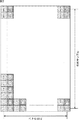
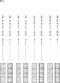
図2は、後述する本技術の第1乃至第6の実施の形態において伝送する対象となる4KのRAWデータの1フレーム分のデータ構成例を示している。図2の各マスは1つの画素を示し、画素内の数字は座標を示している。なお、以下、座標(x,y)の画素を画素(x,y)と表す。
<2. RAW data configuration example>
FIG. 2 shows a data configuration example for one frame of 4K RAW data to be transmitted in the first to sixth embodiments of the present technology to be described later. Each square in FIG. 2 represents one pixel, and the numbers in the pixels represent coordinates. Hereinafter, a pixel at coordinates (x, y) is represented as a pixel (x, y).
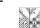
このRAWデータでは、4096サンプル×2160ラインの画素がベイヤ配列に従って並べられている。すなわち、図3に示されるように、Gr(Rの横に隣接する緑)、Gb(Bの横に隣接する緑)、R(赤)及びB(青)の各色にそれぞれ対応する2×2画素のブロック単位(以下、ベイヤ配列単位と称する)で画素が配列されている。例えば、Rに対応する画素(0,0)、Grに対応する画素(1,0)、Gbに対応する画素(0,1)及びBに対応する画素(1,1)の4画素が、1つのベイヤ配列単位を構成する。 In this RAW data, pixels of 4096 samples × 2160 lines are arranged according to the Bayer array. That is, as shown in FIG. 3, 2 × 2 corresponding to each of the colors Gr (green adjacent to R), Gb (green adjacent to B), R (red), and B (blue), respectively. Pixels are arranged in pixel block units (hereinafter referred to as Bayer array units). For example, there are four pixels: a pixel (0,0) corresponding to R, a pixel (1,0) corresponding to Gr, a pixel (0,1) corresponding to Gb, and a pixel (1,1) corresponding to B, One Bayer array unit is configured.
なお、図2の各画素の背景には、図3の各色に対応する画素の背景のパターンに従って、対応する色ごとに異なるパターンが施されている。 The background of each pixel in FIG. 2 has a different pattern for each corresponding color according to the background pattern of the pixel corresponding to each color in FIG.
また、以下、例えば、R(0,0)、Gr(1,0)、Gb(0,1)、B(1,1)のように、各画素を対応する色と座標により表す場合がある。さらに、以下、Gr、Gb、R、Bに対応する画素を、それぞれGrサンプル、Gbサンプル、Rサンプル、Bサンプルとも称する。また、以下、RAWデータをベイヤ配列単位で扱う場合、左端のベイヤ配列単位を0番目のサンプルとし、以下、右方向に1番目のサンプル、2番目のサンプル、・・・と数えることとする。従って、例えば、ベイヤ配列単位で1ライン目の0番目のサンプルには、R(0,0)、Gr(1,0)、Gb(0,1)、B(1,1)が含まれ、1番目のサンプルには、R(2,0)、Gr(3,0)、Gb(2,1)、B(3,1)が含まれる。さらに、以下、ベイヤ配列単位で偶数番目のサンプルを偶数サンプルと称し、奇数番目のサンプルを奇数サンプルと称する。従って、ベイヤ配列単位で、0番目、2番目、4番目・・・のサンプルが偶数サンプルとなり、1番目、3番目、5番目・・・のサンプルが奇数サンプルとなる。 Hereinafter, for example, each pixel may be represented by a corresponding color and coordinate, such as R (0,0), Gr (1,0), Gb (0,1), and B (1,1). . Further, hereinafter, pixels corresponding to Gr, Gb, R, and B are also referred to as Gr sample, Gb sample, R sample, and B sample, respectively. In the following, when RAW data is handled in Bayer array units, the leftmost Bayer array unit is defined as the 0th sample, and hereinafter, it is counted as the first sample, the second sample,. Thus, for example, the 0th sample of the first line in the Bayer array unit includes R (0,0), Gr (1,0), Gb (0,1), B (1,1), The first sample includes R (2, 0), Gr (3, 0), Gb (2, 1), and B (3, 1). Further, hereinafter, even-numbered samples in Bayer array units are referred to as even-numbered samples, and odd-numbered samples are referred to as odd-numbered samples. Therefore, in the Bayer array unit, the 0th, 2nd, 4th... Samples are even samples, and the 1st, 3rd, 5th.
RAWデータの各画素の画素値は、受光レベルを所定のビット数Pで量子化しただけの未加工の値で表される。なお、RAWデータのビット数Pは、例えば、16ビット以下の所定の値(例えば、16ビット、14ビット又は12ビット等)に設定される。 The pixel value of each pixel of the RAW data is represented by an unprocessed value obtained by quantizing the light reception level with a predetermined number of bits P. Note that the number of bits P of the RAW data is set to a predetermined value of 16 bits or less (for example, 16 bits, 14 bits, 12 bits, etc.), for example.
なお、以下、RAWデータ等の映像データの画素値の各ビットを上位から順番に、b15,b14,b13,b12,b11,b10,b9,b8,b7,b6,b5,b4,b3,b2,b1,b0により表す。なお、画素値が16ビット未満である場合にも、同様に画素値の上位からb15,b14,b13・・・の順に表す。例えば、画素値が10ビットの場合、各ビットを上位からb15,b14,b13,b12,b11,b10,b9,b8,b7,b6により表す。 In the following description, each bit of the pixel value of video data such as RAW data is assigned in order from the higher order, b15, b14, b13, b12, b11, b10, b9, b8, b7, b6, b5, b4, b3, b2, This is represented by b1 and b0. When the pixel value is less than 16 bits, the pixel values are similarly represented in the order of b15, b14, b13. For example, when the pixel value is 10 bits, each bit is represented by b15, b14, b13, b12, b11, b10, b9, b8, b7, b6 from the top.
また、以下、SDIフォーマットで規定された10ビット単位(ワード長が10ビット)のデータストリームの10ビットのデータを、上位からB9,B8,B7,B6,B5,B4,B3,B2,B1,B0の順に表す。 In addition, hereinafter, 10-bit data of a 10-bit unit data stream (word length is 10 bits) defined in the SDI format is converted into B9, B8, B7, B6, B5, B4, B3, B2, B1, Expressed in the order of B0.
さらに、以下、mサンプル(画素)×nラインで表される映像データを、m×nと略記する。また、以下、水平方向のサンプル数m×垂直方向のライン数nで1秒当たりのフレーム数fの映像データを、m×n/fと略記する。さらに、以下、フレームレートの範囲をf1−f2により表す。例えば、23.98P−60Pと記載した場合、23.98Hz,24Hz,25Hz,29.97Hz,30Hz,50Hz,59.94Hz,60Hzのフレームレートのプログレッシブ方式の映像データが含まれる。 Further, hereinafter, video data represented by m samples (pixels) × n lines is abbreviated as m × n. Also, hereinafter, video data of the number of samples in the horizontal direction m × the number of lines in the vertical direction n and the number of frames f per second is abbreviated as m × n / f. Further, hereinafter, the range of the frame rate is represented by f1-f2. For example, when 23.98P-60P is described, it includes progressive format video data with frame rates of 23.98 Hz, 24 Hz, 25 Hz, 29.97 Hz, 30 Hz, 50 Hz, 59.94 Hz, and 60 Hz.
また、以下、原色信号伝送方式の赤信号R:緑信号G:青信号Bの比率、又は、色差信号伝送方式の輝度信号Y:第1色差信号Cb:第2色差信号Crの比率を、x:y:zで表す。さらに、以下、R:G:B=x:y:zの映像データを、x:y:z(RGB)の映像データと略記し、Y:Cb:Cr=x:y:zの映像データを、x:y:z(YCbCr)の映像データと略記する。 Further, hereinafter, the ratio of the red signal R: green signal G: blue signal B in the primary color signal transmission system, or the ratio of the luminance signal Y: first color difference signal Cb: second color difference signal Cr in the color difference signal transmission system is expressed as x: y: represented by z. Further, hereinafter, video data of R: G: B = x: y: z is abbreviated as video data of x: y: z (RGB), and video data of Y: Cb: Cr = x: y: z is referred to as “x: y: z (RGB)”. , X: y: z (YCbCr) video data.
また、以下、HD-SDIフォーマットで規定されたデータストリームをHD-SDIのデータストリーム又は単にHD-SDIと略記する場合がある。さらに、以下、3G-SDIフォーマットで規定されたデータストリームを3G-SDIのデータストリーム又は単に3G-SDIと略記する場合がある。 Hereinafter, a data stream defined in the HD-SDI format may be abbreviated as an HD-SDI data stream or simply HD-SDI. Furthermore, hereinafter, a data stream defined in the 3G-SDI format may be abbreviated as a 3G-SDI data stream or simply 3G-SDI.
<3.第1の実施の形態>
次に、図4乃至図13を参照して、本技術の第1の実施の形態について説明する。本技術の第1の実施の形態は、SMPTE 425-1に規定される3G-SDIのレベルBの規定に従って、23.98P-30Pの4Kのベイヤ配列のRAWデータを2チャネルのデータストリームにより伝送できるようにするものである。
<3. First Embodiment>
Next, a first embodiment of the present technology will be described with reference to FIGS. 4 to 13. In the first embodiment of the present technology, 23.98P-30P 4K Bayer array RAW data can be transmitted as a two-channel data stream in accordance with the 3G-SDI level B standard defined in SMPTE 425-1. It is what you want to do.
[放送用カメラ11aの回路構成例]
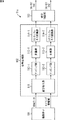
図4は、図1の放送用カメラ11の第1の実施の形態である放送用カメラ11aの一部の機能の構成例を示すブロック図である。
[Circuit Configuration Example of
FIG. 4 is a block diagram showing a configuration example of a part of the function of the
放送用カメラ11aは、撮像素子101、信号処理部102及び送信制御部103を含むように構成される。また、信号処理部102は、並び替え部111、マッピング部112−1,112−2、多重部113−1,113−2、及び、スクランブル・P/S(パラレル/シリアル)変換部114−1,114−2を含むように構成される。
The
撮像素子101は、例えば、CMOSイメージセンサ、CCDイメージセンサ等により構成される。撮像素子101は、撮影の結果得られる23.98P-30Pの4KのRAWデータを信号処理部102の並び替え部111に供給する。また、撮像素子101は、信号処理部102の処理に必要なタイミング情報等を並び替え部111に供給する。
The
並び替え部111は、図7等を参照して後述するように、RAWデータの各画素データを上位8ビットと下位8ビットに分割するとともに、画素データの並び替えを行う。並び替え部111は、並び替えた後の上位8ビットの画素データのデータ列をマッピング部112−1に供給し、下位8ビットの画素データのデータ列をマッピング部112−2に供給する。
As will be described later with reference to FIG. 7 and the like, the
マッピング部112−1は、後述するように、並び替え部111から供給される画素データを多重した複数のデータストリームを生成し、多重部113−1に供給する。同様に、マッピング部112−2は、並び替え部111から供給される画素データを多重した複数のデータストリームを生成し、多重部113−2に供給する。
As described later, the mapping unit 112-1 generates a plurality of data streams obtained by multiplexing the pixel data supplied from the
多重部113−1は、後述するように、マッピング部112−1から供給される複数のデータストリームを多重化することにより、3G-SDIのCh1のデータストリームを生成し、スクランブル・P/S変換部114−1に供給する。同様に、多重部113−2は、マッピング部112−2から供給される複数のデータストリームを多重化することにより、3G-SDIのCh2のデータストリームを生成し、スクランブル・P/S変換部114−2に供給する。 As will be described later, the multiplexing unit 113-1 generates a 3G-SDI Ch1 data stream by multiplexing a plurality of data streams supplied from the mapping unit 112-1, and scrambles and P / S converts the data stream. To the unit 114-1. Similarly, the multiplexing unit 113-2 generates a 3G-SDI Ch2 data stream by multiplexing the plurality of data streams supplied from the mapping unit 112-2, and scrambles / P / S conversion unit 114. -2.
スクランブル・P/S変換部114−1は、後述するように、3G-SDIのCh1のデータストリームのスクランブル及びP/S(パラレル/シリアル)変換を行い、処理後のデータストリームを送信制御部103に供給する。同様に、スクランブル・P/S変換部114−2は、3G-SDIのCh2のデータストリームのスクランブル及びP/S変換を行い、処理後のデータストリームを送信制御部103に供給する。
As will be described later, the scramble / P / S converter 114-1 performs scramble and P / S (parallel / serial) conversion of the 3G-SDI Ch1 data stream, and transmits the processed data stream to the
送信制御部103は、3G-SDIのCh1及びCh2のデータストリームのCCU12aへの送信を制御する。
The
[CCU12aの回路構成例]
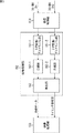
図5は、図1のCCU12の第1の実施の形態であるCCU12aの一部の機能の構成例を示すブロック図である。
[CCU 12a circuit configuration example]
FIG. 5 is a block diagram illustrating a configuration example of a part of functions of the CCU 12a which is the first embodiment of the
CCU12aは、受信制御部151、信号処理部152及び映像処理部153を含むように構成される。また、受信制御部151は、S/P(シリアル/パラレル)変換・デスクランブル部161−1,161−2、分離部162−1,162−2、及び、再生部163を含むように構成される。
The CCU 12a is configured to include a
受信制御部151は、各放送用カメラ11aからの3G-SDIのCh1及びCh2のデータストリームの受信を制御する。受信制御部151は、受信した3G-SDIのCh1のデータストリームをS/P変換・デスクランブル部161−1に供給し、3G-SDIのCh2のデータストリームをS/P変換・デスクランブル部161−2に供給する。
The
S/P変換・デスクランブル部161−1は、3G-SDIのCh1のデータストリームのS/P(シリアル/パラレル)変換及びデスクランブルを行い、処理後のデータストリームを分離部162−1に供給する。同様に、S/P変換・デスクランブル部161−2は、3G-SDIのCh2のデータストリームのS/P変換及びデスクランブルを行い、処理後のデータストリームを分離部162−2に供給する。 The S / P conversion / descrambling unit 161-1 performs S / P (serial / parallel) conversion and descrambling of the 3G-SDI Ch1 data stream, and supplies the processed data stream to the separation unit 162-1 To do. Similarly, the S / P conversion / descrambling unit 161-2 performs S / P conversion and descrambling of the 3G-SDI Ch2 data stream, and supplies the processed data stream to the separation unit 162-2.
分離部162−1は、3G-SDIのCh1のデータストリームを複数のデータストリームに分離して再生部163に供給する。同様に、分離部162−2は、3G-SDIのCh2のデータストリームを複数のデータストリームに分離して再生部163に供給する。
The separation unit 162-1 separates the 3G-SDI Ch1 data stream into a plurality of data streams and supplies the data stream to the
再生部163は、分離部162−1及び分離部162−2から供給されるデータストリームから元のRAWデータを復元し、映像処理部153に供給する。また、再生部163は、映像処理部153の処理に必要なタイミング情報等を映像処理部153に供給する。
The
映像処理部153は、RAWデータに対する各種の処理を行う装置により構成され、再生部163から供給されるRAWデータに対して所定の処理を行う。例えば、映像処理部153は、RAWデータに基づく映像を表示するディスプレイ、RAWデータを記憶する記憶装置等により構成される。
The
[RAWデータ送信処理]
次に、図6のフローチャートを参照して、放送用カメラ11aにより実行されるRAWデータ送信処理について説明する。なお、この処理は1フレーム分のRAWデータを送信する場合の処理を示しており、複数フレームのRAWデータを送信する場合には、この処理が繰り返し実行される。
[RAW data transmission processing]
Next, RAW data transmission processing executed by the
図2のRAWデータは、色毎のサンプル数の比が、G:B:R=2:1:1であるため、4:2:2(YCbCr)の映像データと同様のデータ構造を有しているとみなすことができる。すなわち、RAWデータの1つのベイヤ配列単位が、4:2:2(YCbCr)の映像データの水平方向に隣接する2画素分と同様のデータ構造を有しているとみなすことができる。そして、ベイヤ配列単位で換算すると、図2のRAWデータは、2048サンプル×1080ラインの4:2:2(YCbCr)の映像データと同様のデータ構造を有しているとみなすことができる。 The RAW data in FIG. 2 has the same data structure as 4: 2: 2 (YCbCr) video data because the ratio of the number of samples for each color is G: B: R = 2: 1: 1. Can be considered. That is, it can be considered that one Bayer array unit of RAW data has the same data structure as two pixels adjacent in the horizontal direction of 4: 2: 2 (YCbCr) video data. When converted in Bayer array units, the RAW data in FIG. 2 can be regarded as having the same data structure as the 4: 2: 2 (YCbCr) video data of 2048 samples × 1080 lines.
そこで、放送用カメラ11aは、RAWデータの画素をベイヤ配列単位で水平方向に1サンプルずつ交互に間引くことにより、2つのRAWデータに分離して送信する。これにより、2048サンプル×1080ラインの2Kの4:2:2(YCbCr)の映像データを2つ並行して送信する場合と同様の処理により、RAWデータを送信することができる。
Therefore, the
ステップS1において、並び替え部111は、画素データの並び替えを行う。すなわち、並び替え部111は、RAWデータの画素データを、図7の左側に示されるデータ列に並べ替える。
In step S1, the
具体的には、図7の1行目のデータ列は、RAWデータの左から右方向かつ上から下方向の順番(ラスタスキャン順)に従って、ベイヤ配列単位の偶数サンプルに含まれるGrサンプル及びGbサンプルの画素データの上位8ビット(b15−b9)を、Gr、Gb、Gr、Gb・・・の順に並べたものである。 Specifically, the data column in the first row in FIG. 7 includes Gr samples and Gb included in even-numbered samples in the Bayer array unit according to the order of RAW data from left to right and from top to bottom (raster scan order). The upper 8 bits (b15-b9) of the sample pixel data are arranged in the order of Gr, Gb, Gr, Gb.
2行目のデータ列は、RAWデータの左から右方向かつ上から下方向の順番に従って、ベイヤ配列単位の偶数サンプルに含まれるBサンプル及びRサンプルの画素データの上位8ビットを、B、R、B、R・・・の順に並べたものである。 The data row in the second row includes the upper 8 bits of the pixel data of B samples and R samples included in the even samples of the Bayer array unit in accordance with the order of RAW data from left to right and from top to bottom. , B, R...
3行目のデータ列は、RAWデータの左から右方向かつ上から下方向の順番に従って、ベイヤ配列単位の奇数サンプルに含まれるGrサンプル及びGbサンプルの画素データの上位8ビットを、Gr、Gb、Gr、Gb・・・の順に並べたものである。 The data row in the third row is the upper 8 bits of the pixel data of the Gr sample and Gb sample included in the odd sample of the Bayer arrangement unit in the order from left to right and from top to bottom of the RAW data. , Gr, Gb,...
4行目のデータ列は、RAWデータの左から右方向かつ上から下方向の順番に従って、ベイヤ配列単位の奇数サンプルに含まれるBサンプル及びRサンプルの画素データの上位8ビットを、B、R、B、R・・・の順に並べたものである。 The data column in the fourth row includes the upper 8 bits of the pixel data of the B sample and the R sample included in the odd samples of the Bayer array unit in accordance with the order from the left to the right and from the top to the bottom of the RAW data. , B, R...
5行目のデータ列は、RAWデータの左から右方向かつ上から下方向の順番に従って、ベイヤ配列単位の偶数サンプルに含まれるGrサンプル及びGbサンプルの画素データの下位8ビットを、Gr、Gb、Gr、Gb・・・の順に並べたものである。 The data row in the fifth row includes the lower 8 bits of the pixel data of the Gr sample and Gb sample included in the even sample of the Bayer array unit in the order from the left to the right and from the top to the bottom of the RAW data. , Gr, Gb,...
6行目のデータ列は、RAWデータの左から右方向かつ上から下方向の順番に従って、ベイヤ配列単位の偶数サンプルに含まれるBサンプル及びRサンプルの画素データの下位8ビットを、B、R、B、R・・・の順に並べたものである。 The data string in the sixth row includes the lower 8 bits of the pixel data of B samples and R samples included in the even samples of the Bayer array unit according to the order from the left to the right and from the top to the bottom of the RAW data. , B, R...
7行目のデータ列は、RAWデータの左から右方向かつ上から下方向の順番に従って、ベイヤ配列単位の奇数サンプルに含まれるGrサンプル及びGbサンプルの画素データの下位8ビットを、Gr、Gb、Gr、Gb・・・の順に並べたものである。 The seventh row of data columns includes the lower 8 bits of the pixel data of Gr samples and Gb samples included in odd-numbered samples of the Bayer array unit in the order from left to right and from top to bottom of RAW data. , Gr, Gb,...
8行目のデータ列は、RAWデータの左から右方向かつ上から下方向の順番に従って、ベイヤ配列単位の奇数サンプルに含まれるBサンプル及びRサンプルの画素データの下位8ビットを、B、R、B、R・・・の順に並べたものである。 The data string in the eighth row includes the lower 8 bits of the B sample and R sample pixel data included in the odd sample of the Bayer arrangement unit in accordance with the order from the left to the right and from the top to the bottom of the RAW data. , B, R...
そして、並び替え部111は、図7の1行目から4行目までのデータ列をマッピング部112−1に供給し、5行目から8行目までのデータ列をマッピング部112−2に供給する。
Then, the
ステップS2において、マッピング部112−1,112−2は、画素データのマッピングを行う。具体的には、マッピング部112−1は、図7の1行目の画素データを、図8の上側に示されるように、SMPTE 274M等に規定されるHD-SDIのYチャネル(Y信号)のデータストリーム(以下、Yチャネルデータストリームと称する)に多重する。すなわち、RAWデータのベイヤ配列単位の偶数サンプルに含まれるGサンプルの画素データの上位8ビット(b15−b8)のうち、上位6ビット(b15−b10)が、Yチャネルデータストリームの有効映像データ領域の上位6ビット(B9−B4)に多重される。また、RAWデータのベイヤ配列単位の偶数サンプルに含まれるGサンプルの画素データの上位8ビット(b15−b9)のうち、下位2ビット(b9−b8)が、Yチャネルデータストリームの有効映像データ領域の下位2ビット(B1−B0)に多重される。 In step S2, the mapping units 112-1 and 112-2 perform pixel data mapping. Specifically, the mapping unit 112-1 converts the pixel data of the first row in FIG. 7 into an HD-SDI Y channel (Y signal) defined in SMPTE 274M or the like as shown in the upper side of FIG. Are multiplexed into a data stream (hereinafter referred to as a Y channel data stream). That is, among the upper 8 bits (b15-b8) of the G sample pixel data included in the even samples of the RAW data Bayer array unit, the upper 6 bits (b15-b10) are the effective video data area of the Y channel data stream. Are multiplexed into the upper 6 bits (B9-B4). Also, among the upper 8 bits (b15-b9) of the G sample pixel data included in the even samples of the RAW data Bayer array unit, the lower 2 bits (b9-b8) are the effective video data area of the Y channel data stream. Are multiplexed into the lower two bits (B1-B0).
また、マッピング部112−1は、図7の2行目の画素データを、図8の下側に示されるように、SMPTE 274M等に規定されるHD-SDIのCb/Crチャネル(Cb/Cr信号)のデータストリーム(以下、Cチャネルデータストリームと称する)に多重する。すなわち、RAWデータのベイヤ配列単位の偶数サンプルに含まれるBサンプル及びRサンプルの画素データの上位8ビット(b15−b8)のうち、上位6ビット(b15−b10)が、Cチャネルデータストリームの有効映像データ領域の上位6ビット(B9−B4)に多重される。また、RAWデータのベイヤ配列単位の偶数サンプルに含まれるBサンプル及びRサンプルの画素データの上位8ビット(b15−b9)のうち、下位2ビット(b9−b8)が、Cチャネルデータストリームの有効映像データ領域の下位2ビット(B1−B0)に多重される。なお、Bサンプルの画素データは、CチャネルデータストリームのCbチャネルの領域に多重され、Rサンプルの画素データは、CチャネルデータストリームのCrチャネルの領域に多重される。 Further, the mapping unit 112-1 converts the pixel data in the second row of FIG. 7 into an HD-SDI Cb / Cr channel (Cb / Cr channel) defined in SMPTE 274M or the like as shown in the lower side of FIG. Signal) data stream (hereinafter referred to as C channel data stream). That is, among the upper 8 bits (b15-b8) of the B sample and R sample pixel data included in the even samples in the Bayer array unit of the RAW data, the upper 6 bits (b15-b10) are valid for the C channel data stream. Multiplexed in the upper 6 bits (B9-B4) of the video data area. The lower 2 bits (b9-b8) of the upper 8 bits (b15-b9) of the B sample and R sample pixel data included in the even samples of the RAW data Bayer array unit are valid for the C channel data stream. Multiplexed in the lower 2 bits (B1-B0) of the video data area. The B sample pixel data is multiplexed in the Cb channel region of the C channel data stream, and the R sample pixel data is multiplexed in the Cr channel region of the C channel data stream.
さらに、マッピング部112−1は、図7の3行目の画素データを、1行目の画素データと同様にして、Yチャネルデータストリームに多重する。また、マッピング部112−1は、図7の4行目の画素データを、2行目の画素データと同様にして、Cチャネルデータストリームに多重する。 Further, the mapping unit 112-1 multiplexes the pixel data of the third row in FIG. 7 into the Y channel data stream in the same manner as the pixel data of the first row. Further, the mapping unit 112-1 multiplexes the pixel data in the fourth row in FIG. 7 into the C channel data stream in the same manner as the pixel data in the second row.
マッピング部112−2は、図7の5行目の画素データを、図9の上側に示されるようにYチャネルデータストリームに多重する。すなわち、RAWデータのベイヤ配列単位の偶数サンプルに含まれるGサンプルの画素データの下位8ビット(b7−b0)のうち、上位6ビット(b7−b2)が、Yチャネルデータストリームの有効映像データ領域の上位6ビット(B9−B4)に多重される。また、RAWデータのベイヤ配列単位の偶数サンプルに含まれるGサンプルの画素データの下位8ビット(b7−b0)のうち、下位2ビット(b1−b0)が、Yチャネルデータストリームの有効映像データ領域の下位2ビット(B1−B0)に多重される。なお、RAWデータの画素データが16ビット未満である場合、有効映像データ領域のビットの中に画素データが多重されないビットが生じるが、そのビットには、任意の値を設定することができる。 The mapping unit 112-2 multiplexes the pixel data in the fifth row of FIG. 7 into the Y channel data stream as shown in the upper side of FIG. That is, the upper 6 bits (b7-b2) of the lower 8 bits (b7-b0) of the G sample pixel data included in the even-numbered samples of the RAW data Bayer array unit are the effective video data area of the Y channel data stream. Are multiplexed into the upper 6 bits (B9-B4). Also, among the lower 8 bits (b7-b0) of the G sample pixel data included in the even samples in the Bayer array unit of the RAW data, the lower 2 bits (b1-b0) are the effective video data area of the Y channel data stream. Are multiplexed into the lower two bits (B1-B0). When the pixel data of the RAW data is less than 16 bits, a bit in which the pixel data is not multiplexed is generated in the bits of the effective video data area. An arbitrary value can be set for the bit.
また、マッピング部112−2は、図7の6行目の画素データを、図9の下側に示されるようにCチャネルデータストリームに多重する。すなわち、RAWデータのベイヤ配列単位の偶数サンプルに含まれるBサンプル及びRサンプルの画素データの下位8ビット(b7−b0)のうち、上位6ビット(b7−b2)が、Cチャネルデータストリームの有効映像データ領域の上位6ビット(B9−B4)に多重される。また、RAWデータのベイヤ配列単位の偶数サンプルに含まれるBサンプル及びRサンプルの画素データの下位8ビット(b7−b0)のうち、下位2ビット(b1−b0)が、Cチャネルデータストリームの有効映像データ領域の下位2ビット(B1−B0)に多重される。なお、Bサンプルの画素データは、CチャネルデータストリームのCbチャネルの領域に多重され、Rサンプルの画素データは、CチャネルデータストリームのCrチャネルの領域に多重される。また、RAWデータの画素データが16ビット未満である場合、有効映像データ領域のビットの中に画素データが多重されないビットが生じるが、そのビットには、任意の値を設定することができる。 Further, the mapping unit 112-2 multiplexes the pixel data in the sixth row in FIG. 7 into the C channel data stream as shown in the lower side of FIG. That is, the upper 6 bits (b7-b2) of the lower 8 bits (b7-b0) of the B sample and R sample pixel data included in the even samples in the Bayer array unit of the RAW data are valid C channel data streams. Multiplexed in the upper 6 bits (B9-B4) of the video data area. Also, among the lower 8 bits (b7-b0) of the B sample and R sample pixel data included in the even samples of the RAW data Bayer array unit, the lower 2 bits (b1-b0) are valid for the C channel data stream. Multiplexed in the lower 2 bits (B1-B0) of the video data area. The B sample pixel data is multiplexed in the Cb channel region of the C channel data stream, and the R sample pixel data is multiplexed in the Cr channel region of the C channel data stream. Further, when the pixel data of the RAW data is less than 16 bits, a bit in which the pixel data is not multiplexed is generated in the bits of the effective video data area, and an arbitrary value can be set for the bit.
さらに、マッピング部112−2は、図7の7行目の画素データを、5行目の画素データと同様にして、Yチャネルデータストリームに多重する。また、マッピング部112−2は、図7の8行目の画素データを、6行目の画素データと同様にして、Cチャネルデータストリームに多重する。 Further, the mapping unit 112-2 multiplexes the pixel data of the seventh row in FIG. 7 into the Y channel data stream in the same manner as the pixel data of the fifth row. Further, the mapping unit 112-2 multiplexes the pixel data in the eighth row in FIG. 7 into the C channel data stream in the same manner as the pixel data in the sixth row.
以上のようにして、RAWデータの画素データが、4つのYチャネルデータストリーム及び4つのCチャネルデータストリームに多重される。 As described above, pixel data of RAW data is multiplexed into four Y channel data streams and four C channel data streams.
また、マッピング部112−1及びマッピング部112−2は、各データストリームの有効映像データ領域及び水平補助データ領域(HANC)の画素データが多重されないB3,B2の2ビットに異なる値を設定する。例えば、図8及び図9に示されるように、B3=1、B2=0の固定値が設定される。或いは、B3=0、B2=1の固定値を設定したり、ワード毎に、B3=1、B2=0か、B3=0、B2=1のいずれかを可変で設定するようにしてもよい。 Also, the mapping unit 112-1 and the mapping unit 112-2 set different values for the two bits B3 and B2 in which the pixel data of the effective video data region and the horizontal auxiliary data region (HANC) of each data stream are not multiplexed. For example, as shown in FIGS. 8 and 9, fixed values of B3 = 1 and B2 = 0 are set. Alternatively, a fixed value of B3 = 0 and B2 = 1 may be set, or B3 = 1 and B2 = 0 or B3 = 0 and B2 = 1 may be variably set for each word. .
これにより、データストリームの有効映像データ領域及び水平補助データ領域に、HD-SDI及び3G-SDIで禁止されている000h乃至003h及び3FCh乃至3FFhの禁止コードが設定されるのを防ぐことができる。すなわち、これらの禁止コードは、10ビットのうちの上位8ビットが同じ値であるが、有効映像データ領域及び水平補助データ領域のB3,B2の2ビットに異なる値を設定することにより、上位8ビットに同じ値が設定されることが防止される。なお、hは16進表現であることを示している。 Thereby, it is possible to prevent the prohibition codes of 000h to 003h and 3FCh to 3FFh, which are prohibited by HD-SDI and 3G-SDI, from being set in the effective video data area and the horizontal auxiliary data area of the data stream. That is, these prohibition codes have the same value in the upper 8 bits of the 10 bits, but by setting different values in the 2 bits of B3 and B2 in the effective video data area and the horizontal auxiliary data area, It is prevented that the same value is set in the bits. Note that h indicates hexadecimal representation.
なお、以下、図7の1行目、3行目、5行目、7行目の画素データが多重されたデータストリームを、Yチャネルデータストリーム1、2、3又は4と称する。また、以下、図7の2行目、4行目、6行目、8行目の画素データが多重されたデータストリームを、それぞれCチャネルデータストリーム1、2、3又は4と称する。 Hereinafter, the data stream in which the pixel data of the first row, the third row, the fifth row, and the seventh row in FIG. Hereinafter, the data streams in which the pixel data in the second row, the fourth row, the sixth row, and the eighth row in FIG.
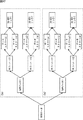
ステップS3において、マッピング部112−1及びマッピング部112−2は、HD-SDI相当のデータストリームを生成する。具体的には、マッピング部112−1及びマッピング部112−2は、SMPTE 274、SMPTE 292-1、又は、SMPTE 424M/425-1の規定に従って、水平ブランキングデータ(H-Blank)、垂直ブランキングデータ(V-Blank)、SAV(Start of Active Video)、EAV(End of Active Video)、LN(Line Number)、CRCC(Cyclic Redundancy Check)を各データストリームに付加する。 In step S3, the mapping unit 112-1 and the mapping unit 112-2 generate a data stream corresponding to HD-SDI. Specifically, the mapping unit 112-1 and the mapping unit 112-2 are configured to perform horizontal blanking data (H-Blank) and vertical blanking according to SMPTE 274, SMPTE 292-1, or SMPTE 424M / 425-1, respectively. Ranking data (V-Blank), SAV (Start of Active Video), EAV (End of Active Video), LN (Line Number), and CRCC (Cyclic Redundancy Check) are added to each data stream.
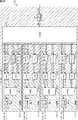
また、マッピング部112−1は、Yチャネルデータストリーム1とCチャネルデータストリーム1をワード単位でバイトインタリーブして多重化することにより、図10の3G-SDIのCh1のリンクAのデータストリームを生成する。このデータストリームは、HD-SDI相当のデータストリームであり、SMPTE 425-1の図5のリンクAのデータストリームと同様のデータ構造を有している。また、このデータストリームは、RAWデータのベイヤ配列単位の偶数サンプルに含まれるGr、Gb、B、Rの各サンプルの画素データの上位8ビットが多重されたものである。換言すれば、このデータストリームは、RAWデータのベイヤ配列単位の偶数サンプルを抽出することにより生成されるRAWデータの各画素データの上位8ビットが多重されたものである。
Also, the mapping unit 112-1 generates a data stream of the link A of Ch1 of 3G-SDI in FIG. 10 by multiplexing the Y
同様に、マッピング部112−1は、Yチャネルデータストリーム2とCチャネルデータストリーム2をワード単位でバイトインタリーブして多重化することにより、図10の3G-SDIのCh1のリンクBのデータストリームを生成する。このデータストリームは、HD-SDI相当のデータストリームであり、SMPTE 425-1の図5のリンクBのデータストリームと同様のデータ構造を有している。また、このデータストリームは、RAWデータのベイヤ配列単位の奇数サンプルに含まれるGr、Gb、B、Rの各サンプルの画素データの上位8ビットが多重されたものである。換言すれば、このデータストリームは、RAWデータのベイヤ配列単位の奇数サンプルを抽出することにより生成されるRAWデータの各画素データの上位8ビットが多重されたものである。
Similarly, the mapping unit 112-1 multiplexes the Y
このように、RAWデータのGr、Gb、B、Rの各サンプルの画素データの上位8ビットが、画素(サンプル)単位(より正確にはベイヤ配列単位)で2つのデータストリームに分けて多重される。 As described above, the upper 8 bits of the pixel data of the Gr, Gb, B, and R samples of the RAW data are divided and multiplexed into two data streams in pixel (sample) units (more precisely, Bayer array units). The
また、マッピング部112−2は、Yチャネルデータストリーム3とCチャネルデータストリーム3をワード単位でバイトインタリーブして多重化することにより、図10の3G-SDIのCh2のリンクAのデータストリームを生成する。このデータストリームは、HD-SDI相当のデータストリームであり、SMPTE 425-1の図5のリンクAのデータストリームと同様のデータ構造を有している。また、このデータストリームは、RAWデータのベイヤ配列単位の偶数サンプルに含まれるGr、Gb、B、Rの各サンプルの画素データの下位8ビットが多重されたものである。換言すれば、このデータストリームは、RAWデータのベイヤ配列単位の偶数サンプルを抽出することにより生成されるRAWデータの各画素データの下位8ビットが多重されたものである。
Also, the mapping unit 112-2 generates a data stream of the link A of Ch2 of 3G-SDI in FIG. 10 by multiplexing the Y
同様に、マッピング部112−2は、Yチャネルデータストリーム4とCチャネルデータストリーム4をワード単位でバイトインタリーブして多重化することにより、図10の3G-SDIのCh2のリンクBのデータストリームを生成する。このデータストリームは、HD-SDI相当のデータストリームであり、SMPTE 425-1の図5のリンクBのデータストリームと同様のデータ構造を有している。また、このデータストリームは、RAWデータのベイヤ配列単位の奇数サンプルに含まれるGr、Gb、B、Rの各サンプルの画素データの下位8ビットが多重されたものである。このデータストリームは、RAWデータのベイヤ配列単位の奇数サンプルを抽出することにより生成されるRAWデータの各画素データの下位8ビットが多重されたものである。
Similarly, the mapping unit 112-2 multiplexes the Y-
このように、RAWデータのGr、Gb、B、Rの各サンプルの画素データの下位8ビットが、画素(サンプル)単位(より正確にはベイヤ配列単位)で2つのデータストリームに分けて多重される。 In this way, the lower 8 bits of the pixel data of Gr, Gb, B, and R samples of RAW data are divided and multiplexed into two data streams in pixel (sample) units (more precisely, Bayer array units). The
そして、マッピング部112−1は、3G-SDIのCh1のリンクA及びリンクBのデータストリームを多重部113−1に供給する。マッピング部112−2は、3G-SDIのCh2のリンクA及びリンクBのデータストリームを多重部113−2に供給する。 Then, the mapping unit 112-1 supplies the data stream of the 3G-SDI Ch1 link A and link B to the multiplexing unit 113-1. The mapping unit 112-2 supplies the data stream of the link A and the link B of Ch2 of 3G-SDI to the multiplexing unit 113-2.
ステップS4において、多重部113−1及び多重部113−2は、3G-SDIのデータストリームを生成する。具体的には、多重部113−1は、3G-SDIのCh1のリンクAとリンクBのデータストリームをワード単位でバイトインタリーブして多重化することにより、3G-SDIのCh1のデータストリームを生成する。このデータストリームは、RAWデータのGr、Gb、B、Rの各サンプルの画素データの上位8ビットが多重されたものである。多重部113−1は、生成した3G-SDIのCh1のデータストリームをスクランブル・P/S変換部114−1に供給する。 In step S4, the multiplexing unit 113-1 and the multiplexing unit 113-2 generate a 3G-SDI data stream. Specifically, the multiplexing unit 113-1 generates the 3G-SDI Ch1 data stream by byte-interleaving and multiplexing the 3G-SDI Ch1 link A and link B data streams in units of words. To do. In this data stream, the upper 8 bits of pixel data of Gr, Gb, B, and R samples of RAW data are multiplexed. The multiplexing unit 113-1 supplies the generated 3G-SDI Ch1 data stream to the scramble / P / S conversion unit 114-1.
多重部113−2は、3G-SDIのCh2のリンクAとリンクBのデータストリームをワード単位でバイトインタリーブして多重化することにより、3G-SDIのCh2のデータストリームを生成する。このデータストリームは、RAWデータのGr、Gb、B、Rの各サンプルの画素データの下位8ビットが多重されたものである。多重部113−2は、生成した3G-SDIのCh2のデータストリームをスクランブル・P/S変換部114−2に供給する。 The multiplexing unit 113-2 generates a 3G-SDI Ch2 data stream by byte-interleaving and multiplexing the 3G-SDI Ch2 link A and link B data streams in units of words. This data stream is obtained by multiplexing the lower 8 bits of pixel data of Gr, Gb, B, and R samples of RAW data. The multiplexing unit 113-2 supplies the generated 3G-SDI Ch2 data stream to the scramble / P / S conversion unit 114-2.
なお、3G-SDI(又はHD-SDI)のデータストリームの有効映像データ領域は、1920又は2048サンプルである。一方、上述したように、図2のRAWデータをベイヤ配列単位で水平方向に1サンプルずつ交互に間引いて、2つのRAWデータに分離することにより、分離後のRAWデータの1ライン当たりのGサンプルのサンプル数、及び、BサンプルとRサンプルの合計サンプル数は、ともに2048サンプルとなる。 The effective video data area of the 3G-SDI (or HD-SDI) data stream is 1920 or 2048 samples. On the other hand, as described above, the RAW data in FIG. 2 is alternately thinned out one sample at a time in the Bayer array unit and separated into two RAW data, so that G samples per line of the separated RAW data are obtained. The total number of samples of B and R samples is 2048 samples.
従って、例えば、3G-SDI(又はHD-SDI)の2048サンプル分の有効映像データ領域に、分離後のRAWデータの全ての画素データを多重することが可能である。或いは、3G-SDI(又はHD-SDI)の1920サンプル分の有効映像データ領域に、分離後のRAWデータの全ての画素データを多重し、有効映像データ領域に多重できない2048−1920=128サンプル分の画素データを水平補助データ領域に多重するようにしてもよい。また、RAWデータの水平ブランキング領域に補助データ等が多重されている場合、そのデータを水平補助データ領域に多重することも可能である。 Therefore, for example, it is possible to multiplex all the pixel data of the RAW data after separation into the effective video data area for 2048 samples of 3G-SDI (or HD-SDI). Alternatively, all the pixel data of the separated RAW data is multiplexed on the effective video data area for 1920 samples of 3G-SDI (or HD-SDI) and cannot be multiplexed on the effective video data area for 2048-1920 = 128 samples. These pixel data may be multiplexed in the horizontal auxiliary data area. Further, when auxiliary data or the like is multiplexed in the horizontal blanking area of RAW data, the data can be multiplexed in the horizontal auxiliary data area.
ステップS5において、スクランブル・P/S変換部114−1及び114−2は、3G-SDIのデータストリームのスクランブル及びP/S変換を行う。具体的には、スクランブル・P/S変換部114−1は、SMPTE 424Mの規定と同様の方法により、3G-SDIのCh1のデータストリームのスクランブルを行う。さらに、スクランブル・P/S変換部114−1は、3G-SDIのCh1のデータストリームをP/S変換し、送信制御部103に供給する。
In step S5, the scramble / P / S converters 114-1 and 114-2 perform scramble and P / S conversion of the 3G-SDI data stream. Specifically, the scramble / P / S converter 114-1 scrambles the 3G-SDI Ch1 data stream by the same method as defined in SMPTE 424M. Further, the scramble / P / S conversion unit 114-1 performs P / S conversion on the Ch1 data stream of 3G-SDI and supplies it to the
同様に、スクランブル・P/S変換部114−2は、SMPTE 424Mの規定と同様の方法により、3G-SDIのCh2のデータストリームのスクランブルを行う。さらに、スクランブル・P/S変換部114−2は、3G-SDIのCh2のデータストリームをP/S変換し、送信制御部103に供給する。
Similarly, the scramble / P / S converter 114-2 scrambles the 3G-SDI Ch2 data stream by the same method as defined in SMPTE 424M. Further, the scramble / P / S converter 114-2 performs P / S conversion on the 3G-SDI Ch2 data stream and supplies the P2 to the
ステップS6において、送信制御部103は、3G-SDIのデータストリームを送信する。すなわち、送信制御部103は、Ch1及びCh2の2チャネルの3G-SDIのシリアル系列のデータストリームを送信することにより、RAWデータをCCU12aに送信する。
In step S6, the
その後、信号送信処理は終了する。 Thereafter, the signal transmission process ends.
[RAWデータ受信処理]
次に、図11のフローチャートを参照して、図6の放送用カメラ11aによるRAWデータ送信処理に対応して、CCU12aにより実行されるRAWデータ受信処理について説明する。
[RAW data reception processing]
Next, the RAW data reception process executed by the CCU 12a in correspondence with the RAW data transmission process by the
ステップS51において、受信制御部151は、3G-SDIのデータストリームを受信する。すなわち、受信制御部151は、放送用カメラ11aから送信されてきた3G-SDIのCh1及びCh2のデータストリームを受信する。受信制御部151は、Ch1のデータストリームをS/P変換・デスクランブル部161−1に供給し、Ch2のデータストリームをS/P変換・デスクランブル部161−2に供給する。
In step S51, the
ステップS52において、S/P変換・デスクランブル部161−1及び161−2は、3G-SDIのデータストリームのS/P変換及びデスクランブルを行う。具体的には、S/P変換・デスクランブル部161−1は、放送用カメラ11aのスクランブル・P/S変換部114−1とは逆の処理により、Ch1のデータストリームのS/P変換及びデスクランブルを行う。S/P変換・デスクランブル部161−1は、処理後のCh1のデータストリームを分離部162−1に供給する。
In step S52, the S / P conversion / descrambling units 161-1 and 161-2 perform S / P conversion and descrambling of the 3G-SDI data stream. Specifically, the S / P conversion / descrambling unit 161-1 performs S / P conversion of the data stream of Ch1 by reverse processing to the scramble / P / S conversion unit 114-1 of the
同様に、S/P変換・デスクランブル部161−2は、Ch2のデータストリームのS/P変換及びデスクランブルを行い、処理後のCh2のデータストリームを分離部162−2に供給する。 Similarly, the S / P conversion / descrambling unit 161-2 performs S / P conversion and descrambling of the Ch2 data stream, and supplies the processed Ch2 data stream to the separation unit 162-2.
ステップS53において、分離部162−1及び162−2は、3G-SDIのデータストリームを分離する。具体的には、分離部162−1は、Ch1のデータストリームのワード同期検出を行い、さらにCh1のデータストリームを図10のリンクAとリンクBに分離し、再生部163に供給する。同様に、分離部162−2は、Ch2のデータストリームを図10のリンクAとリンクBに分離し、再生部163に供給する。
In step S53, the separation units 162-1 and 162-2 separate the 3G-SDI data stream. Specifically, the separation unit 162-1 performs word synchronization detection of the Ch1 data stream, further separates the Ch1 data stream into the link A and the link B in FIG. Similarly, the separation unit 162-2 separates the Ch2 data stream into the link A and the link B in FIG. 10 and supplies them to the
ステップS54において、再生部163は、RAWデータの再生を行う。具体的には、再生部163は、Ch1のデータストリームのリンクA及びリンクBから、RAWデータのGr、Gb、B、Rの各サンプルの画素データの上位8ビットを抽出する。また、再生部163は、Ch2のデータストリームのリンクA及びリンクBから、RAWデータのGr、Gb、B、Rの各サンプルの画素データの下位8ビットを抽出する。
In step S54, the
そして、再生部163は、抽出した各画素データの上位8ビット及び下位8ビットから、元の画素データを復元し、ベイヤ配列に従って並べ替えることにより、元のRAWデータを復元する。そして、再生部163は、復元したRAWデータを映像処理部153に供給する。
Then, the
なお、このとき、RAWデータと異なる形式の映像データに変換して、映像処理部153に供給するようにしてもよい。
At this time, it may be converted into video data of a format different from the RAW data and supplied to the
その後、RAWデータ受信処理は終了する。 Thereafter, the RAW data reception process ends.
このようにして、3G-SDIのレベルBの規定に従って、例えば、既存の3G-SDI用のICや装置を用いて、23.98P-30Pの4Kのベイヤ配列のRAWデータを伝送することができる。また、Ch1のデータストリームには、RAWデータの各画素データの上位8ビットが多重されている。従って、例えば、3G-SDI用の観測装置を用いて、Ch1のデータストリームによりRAWデータの映像を目で見て確認することができる。さらに、各データストリームに付加されているCRCCを用いて、3G-SDIの観測装置により伝送系のエラーをモニタすることができる。 In this way, according to the definition of Level B of 3G-SDI, for example, 23.98P-30P 4K Bayer array RAW data can be transmitted using an existing 3G-SDI IC or device. In the data stream of Ch1, the upper 8 bits of each pixel data of the RAW data are multiplexed. Therefore, for example, using an observation device for 3G-SDI, it is possible to visually check the video of RAW data using the Ch1 data stream. Furthermore, using the CRCC attached to each data stream, it is possible to monitor transmission system errors with a 3G-SDI observation device.
<4.第1の実施の形態の変形例>
以下、上述した第1の実施の形態の変形例について説明する。
<4. Modification of First Embodiment>
Hereinafter, a modification of the first embodiment described above will be described.
[RAWデータの多重方法の変形例]
RAWデータを3G-SDIのデータストリームの各チャネルに多重する方法は、上述した図7等に示す方法に限定されるものではなく、他の方法を採用することが可能である。
[Variation of RAW data multiplexing method]
The method of multiplexing RAW data on each channel of the 3G-SDI data stream is not limited to the method shown in FIG. 7 and the like, and other methods can be adopted.
例えば、図12に示されるように、RAWデータを3G-SDIの各チャネルに多重するようにしてもよい。具体的には、図12と図7を比較すると、B及びRサンプルの画素データの多重方法は共通である一方、Gr及びGbサンプルの画素データの多重方法が異なっている。すなわち、Grサンプルの画素データの上位8ビットが、3G-SDIのCh1のリンクAのデータストリームのYチャネルに多重され、下位8ビットが、3G-SDIのCh2のリンクAのデータストリームのYチャネルに多重される。また、Gbサンプルの画素データの上位8ビットが、3G-SDIのCh1のリンクBのデータストリームのYチャネルに多重され、下位8ビットが、3G-SDIのCh2のリンクBのデータストリームのYチャネルに多重される。 For example, as shown in FIG. 12, RAW data may be multiplexed on each channel of 3G-SDI. Specifically, comparing FIG. 12 and FIG. 7, the multiplexing method of pixel data of B and R samples is common, but the multiplexing method of pixel data of Gr and Gb samples is different. That is, the upper 8 bits of the pixel data of the Gr sample are multiplexed on the Y channel of the link A data stream of 3G-SDI Ch1, and the lower 8 bits are the Y channel of the link A data stream of Ch2 of 3G-SDI. Is multiplexed. The upper 8 bits of the pixel data of the Gb sample are multiplexed on the Y channel of the 3G-SDI Ch1 link B data stream, and the lower 8 bits are the Y channel of the 3G-SDI Ch2 link B data stream. Is multiplexed.
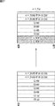
また、図2のRAWデータは、Gb、Gr、B、Rの各サンプルの数が同じであり、ベイヤ配列単位に換算すると2048サンプル×1080ラインの映像データとみなすことができる。従って、図13に示されるように、SMPTE 372の図3及び図4等に示される4:4:4:4(RGB+A)の映像データを3G-SDIのレベルBにより伝送する場合の規定に従って、RAWデータを3G-SDIのデータストリームに多重して伝送することが可能である。
The RAW data in FIG. 2 has the same number of Gb, Gr, B, and R samples, and can be regarded as video data of 2048 samples × 1080 lines when converted to a Bayer array unit. Therefore, as shown in FIG. 13, the specification for transmitting 4: 4: 4: 4 (RGB + A) video data shown in FIG. 3 and FIG. 4 of
具体的には、図7及び図12の場合と同様に、RAWデータの各画素データの上位8ビットが3G-SDIのCh1のデータストリームに多重され、下位8ビットがCh2のデータストリームに多重される。また、この2チャネルのデータストリームは、SMPTE 372の図3及び図4の方法で、2チャネルのHDI-SDIのデータストリームのYチャネル及びCチャネルにRGBAを多重した場合の3G-SDIのレベルBのフォーマットに従う。
Specifically, as in the case of FIGS. 7 and 12, the upper 8 bits of each pixel data of the RAW data are multiplexed on the Ch1 data stream of 3G-SDI, and the lower 8 bits are multiplexed on the Ch2 data stream. The Also, this 2-channel data stream is the level B of 3G-SDI when RGBA is multiplexed on the Y-channel and C-channel of the 2-channel HDI-SDI data stream by the method of
より具体的には、RAWデータのGrサンプルの画素データの上位8ビットが、3G-SDIのレベルBのCh1のデータストリームのGチャネルに多重され、下位8ビットが、3G-SDIのレベルBのCh2のデータストリームのGチャネルに多重される。 More specifically, the upper 8 bits of the pixel data of the Gr sample of RAW data are multiplexed on the G channel of the 3G-SDI level B Ch1 data stream, and the lower 8 bits of the 3G-SDI level B It is multiplexed to the G channel of the Ch2 data stream.
RAWデータのBサンプルの画素データの上位8ビットが、3G-SDIのレベルBのCh1のデータストリームのBチャネルに多重され、下位8ビットが、3G-SDIのレベルBのCh2のデータストリームのBチャネルに多重される。 The upper 8 bits of pixel data of B samples of RAW data are multiplexed on the B channel of the Ch1 data stream of 3G-SDI level B, and the lower 8 bits are B of the Ch2 data stream of 3G-SDI level B Multiplexed into a channel.
RAWデータのRサンプルの画素データの上位8ビットが、3G-SDIのレベルBのCh1のデータストリームのRチャネルに多重され、下位8ビットが、3G-SDIのレベルBのCh2のデータストリームのRチャネルに多重される。 The upper 8 bits of the pixel data of R samples of RAW data are multiplexed on the R channel of the Ch1 data stream of 3G-SDI level B, and the lower 8 bits are R of the Ch2 data stream of 3G-SDI level B Multiplexed into a channel.
RAWデータのGbサンプルの画素データの上位8ビットが、3G-SDIのレベルBのCh1のデータストリームのA(Auxiliary)チャネルに多重され、下位8ビットが、3G-SDIのレベルBのCh2のデータストリームのAチャネルに多重される。 The upper 8 bits of Gb sample pixel data of RAW data are multiplexed on the A (Auxiliary) channel of the Ch1 data stream of 3G-SDI level B, and the lower 8 bits are Ch2 data of level B of 3G-SDI. It is multiplexed on the A channel of the stream.
なお、GrサンプルとGbサンプルを多重するチャネルを逆にしてもよい。すなわち、Grサンプルの画素データを3G-SDIのレベルBのデータストリームのAチャネルに多重し、Gbサンプルの画素データを3G-SDIのレベルBのデータストリームのGチャネルに多重するようにしてもよい。 In addition, you may reverse the channel which multiplexes a Gr sample and a Gb sample. That is, Gr sample pixel data may be multiplexed on the A channel of the 3G-SDI level B data stream, and Gb sample pixel data may be multiplexed on the G channel of the 3G-SDI level B data stream. .
また、図12及び図13のいずれの場合においても、RAWデータの各画素データのビット多重の方法は、図8及び図9を参照して上述した方法と同様である。 In both cases of FIGS. 12 and 13, the method of bit multiplexing each pixel data of the RAW data is the same as the method described above with reference to FIGS.
[HD-SDIを用いて伝送する場合]
以上の説明では、3G-SDIを用いてRAWデータを伝送する例を示したが、HD-SDIを用いて伝送することも可能である。具体的には、図10の3G-SDIのCh1及びCh2のリンクA及びリンクBのデータストリームは、それぞれHD-SDIのデータストリームと同様のデータ構造を有している。従って、各データストリームを個別にスクランブルし、P/S変換して伝送することにより、4チャネルのHD-SDIのデータストリームにより、23.98P-30Pの4KのRAWデータを伝送することが可能になる。
[When transmitting using HD-SDI]
In the above description, an example in which RAW data is transmitted using 3G-SDI has been described, but transmission using HD-SDI is also possible. Specifically, the 3G-SDI Ch1 and Ch2 link A and link B data streams in FIG. 10 each have the same data structure as the HD-SDI data stream. Therefore, each data stream is individually scrambled, P / S converted, and transmitted, so that it is possible to transmit 23.98P-30P 4K RAW data using a 4-channel HD-SDI data stream. .
この場合も、3G-SDIを用いた場合と同様に、例えば、既存のHD-SDI用のICや装置を用いて、23.98P-30Pの4Kのベイヤ配列のRAWデータを伝送することができる。また、HD-SDI用の観測装置を用いて、RAWデータの各画素データの上位8ビットが多重されているデータストリームによりRAWデータの映像を目で見て確認することができる。さらに、各データストリームに付加されているCRCCを用いて、HD-SDIの観測装置により伝送系のエラーをモニタすることができる。 Also in this case, as in the case of using 3G-SDI, for example, 23.98P-30P 4K Bayer array RAW data can be transmitted using an existing HD-SDI IC or device. Also, using an HD-SDI observation device, it is possible to visually check the video of the RAW data with a data stream in which the upper 8 bits of each pixel data of the RAW data are multiplexed. Furthermore, using the CRCC attached to each data stream, it is possible to monitor transmission system errors with an HD-SDI observation device.
[RAWデータの画素データが8ビット以下の場合の伝送方法]
RAWデータの画素データが8ビット以下の場合、図7、図12及び図13の5行目から8行目までのデータ列を伝送する必要がなくなる。従って、1チャネルの3G-SDIのデータストリーム、又は、2チャネルのHD-SDIのデータストリームでRAWデータを伝送することが可能である。
[Transmission method when pixel data of RAW data is 8 bits or less]
When the pixel data of the RAW data is 8 bits or less, it is not necessary to transmit the data string from the 5th line to the 8th line in FIGS. Accordingly, it is possible to transmit RAW data using a 1-
<5.第2の実施の形態>
次に、図14乃至図20を参照して、本技術の第2の実施の形態について説明する。本技術の第2の実施の形態は、SMPTE 372及びSMPTE 425-1に規定される3G-SDIのレベルBの規定に従って、47.95P-60Pの4Kのベイヤ配列のRAWデータを4チャネルのデータストリームにより伝送できるようにするものである。
<5. Second Embodiment>
Next, a second embodiment of the present technology will be described with reference to FIGS. In the second embodiment of the present technology, in accordance with the 3G-SDI level B specification defined in
[放送用カメラ11bの回路構成例]
図14は、図1の放送用カメラ11の第2の実施の形態である放送用カメラ11bの一部の機能の構成例を示すブロック図である。
[Circuit Configuration Example of
FIG. 14 is a block diagram illustrating a configuration example of a part of a function of a
放送用カメラ11bは、撮像素子201、信号処理部202及び送信制御部203を含むように構成される。また、信号処理部202は、分離部211、並び替え部212−1,212−2、マッピング部213−1乃至213−4、多重部214−1乃至214−4、及び、スクランブル・P/S変換部215−1乃至215−4を含むように構成される。
The
撮像素子201は、例えば、CMOSイメージセンサ、CCDイメージセンサ等により構成される。撮像素子201は、撮影の結果得られる47.95P-60Pの4KのRAWデータを信号処理部202の分離部211に供給する。また、撮像素子201は、信号処理部202の処理に必要なタイミング情報等を分離部211に供給する。
The
分離部211は、図17を参照して後述するように、RAWデータをリンクAとリンクBの2チャネルの映像データに分離する。分離部211は、リンクAの映像データを並び替え部212−1に供給し、リンクBの映像データを並び替え部212−2に供給する。
As will be described later with reference to FIG. 17, the
並び替え部212−1は、図4の放送用カメラ11aの並び替え部111と同様に、リンクAの映像データの各画素データを上位8ビットと下位8ビットに分割するとともに、画素データの並び替えを行う。並び替え部212−1は、並び替えた後の上位8ビットの画素データのデータ列をマッピング部213−1に供給し、下位8ビットの画素データのデータ列をマッピング部213−2に供給する。
Similar to the
同様に、並び替え部212−2は、リンクBの映像データの各画素データを上位8ビットと下位8ビットに分割するとともに、画素データの並び替えを行う。並び替え部212−2は、並び替えた後の上位8ビットの画素データのデータ列をマッピング部213−3に供給し、下位8ビットの画素データのデータ列をマッピング部213−4に供給する。 Similarly, the rearrangement unit 212-2 divides each pixel data of the video data of link B into upper 8 bits and lower 8 bits and rearranges the pixel data. The rearrangement unit 212-2 supplies the data sequence of the higher-order 8-bit pixel data after the rearrangement to the mapping unit 213-3, and supplies the data sequence of the lower-order 8-bit pixel data to the mapping unit 213-4. .
マッピング部213−1及び213−2は、図4の放送用カメラ11aのマッピング部112−1,112−2と同様に、それぞれ、並び替え部212−1から供給される画素データを多重した複数のデータストリームを生成する。そして、マッピング部213−1及び213−2は、それぞれ、生成した複数のデータストリームを多重部214−1及び214−2に供給する。同様に、マッピング部213−3及び213−4は、それぞれ、並び替え部212−2から供給される画素データを多重した複数のデータストリームを生成し、多重部214−3及び214−4に供給する。
Similar to the mapping units 112-1 and 112-2 of the
多重部214−1乃至214−4は、それぞれ、図4の放送用カメラ11aの多重部113−1,113−2と同様に、マッピング部213−1乃至213−4から供給される複数のデータストリームを多重化することにより、3G-SDIのCh1乃至Ch4のデータストリームを生成する。そして、多重部214−1乃至214−4は、それぞれ、生成した3G-SDIのCh1乃至Ch4のデータストリームをスクランブル・P/S変換部215−1乃至215−4に供給する。
The multiplexing units 214-1 to 214-4 are each a plurality of data supplied from the mapping units 213-1 to 213-4, similarly to the multiplexing units 113-1 and 113-2 of the
スクランブル・P/S変換部215−1乃至215−4は、それぞれ、図4の放送用カメラ11aのスクランブル・P/S変換部114−1,114−2と同様に、3G-SDIのCh1乃至Ch4のデータストリームのスクランブル及びP/S変換を行う。そして、スクランブル・P/S変換部215−1乃至215−4は、それぞれ、処理後のデータストリームを送信制御部203に供給する。
The scramble / P / S converters 215-1 to 215-4 are similar to the scramble / P / S converters 114-1 and 114-2 of the
送信制御部203は、3G-SDIのCh1乃至Ch4のデータストリームのCCU12bへの送信を制御する。
The
[CCU12bの回路構成例]
図15は、図1のCCU12の第2の実施の形態であるCCU12bの一部の機能の構成例を示すブロック図である。なお、図中、図5と対応する部分には、同じ符号を付してあり、処理が同じ部分については、その説明は適宜省略する。
[
FIG. 15 is a block diagram showing a configuration example of a part of functions of the
CCU12bは、受信制御部251、信号処理部252及び映像処理部153を含むように構成される。また、信号処理部252は、S/P変換・デスクランブル部261−1乃至261−4、分離部262−1乃至261−4、及び、再生部263を含むように構成される。
The
受信制御部251は、各放送用カメラ11bからの3G-SDIのCh1乃至Ch4のデータストリームの受信を制御する。受信制御部251は、受信した3G-SDIのCh1乃至Ch4のデータストリームを、S/P変換・デスクランブル部261−1乃至261−4に供給する。
The
S/P変換・デスクランブル部261−1乃至261−4は、それぞれ、3G-SDIのCh1乃至Ch4のデータストリームのS/P変換及びデスクランブルを行い、処理後のデータストリームを分離部262−1乃至262−4に供給する。 The S / P conversion / descrambling units 261-1 to 261-4 perform S / P conversion and descrambling of 3G-SDI Ch1 to Ch4 data streams, respectively, and separate the processed data stream into a separation unit 262- 1 to 262-4.
分離部262−1乃至262−4は、それぞれ、3G-SDIのCh1乃至Ch4のデータストリームを複数のデータストリームに分離して再生部263に供給する。
The demultiplexing units 262-1 to 262-4 demultiplex the 3G-SDI Ch1 to Ch4 data streams into a plurality of data streams, and supply the data streams to the
再生部263は、分離部262−1乃至分離部262−4から供給されるデータストリームから元のRAWデータを復元し、映像処理部153に供給する。また、再生部263は、映像処理部153の処理に必要なタイミング情報等を映像処理部153に供給する。
The
[RAWデータ送信処理]
次に、図16のフローチャートを参照して、放送用カメラ11bにより実行されるRAWデータ送信処理について説明する。なお、この処理は2フレーム分のRAWデータを送信する場合の処理を示しており、3フレーム以上のRAWデータを送信する場合には、この処理が繰り返し実行される。
[RAW data transmission processing]
Next, the RAW data transmission process executed by the
ステップS101において、分離部211は、RAWデータを2チャネルの映像データに分離する。
In step S101, the
この第2の実施の形態のRAWデータのフレームレートは、第1の実施の形態のRAWデータのフレームレートの2倍である。そこで、分離部211は、SMPTE 372の図2の規定に従って、図17に示されるように、水平ブランキング領域を含めてRAWデータのベイヤ配列単位の水平方向のラインを交互に間引くことにより、RAWデータを23.98P-30P(47.95I-60I)相当の2チャネルの映像データに分離する。
The frame rate of the RAW data in the second embodiment is twice the frame rate of the RAW data in the first embodiment. Therefore, in accordance with the definition of FIG. 2 of
具体的には、図17に示されるように、RAWデータを2フレーム単位でリンクAとリンクBの2チャネルの映像データに分離する。なお、リンクAとリンクBの中に示されている番号は、RAWデータの水平ブランキング領域を含めたベイヤ配列単位のライン番号を示している。なお、例えば、図2のRAWデータのいちばん上のラインと次のラインを合わせたラインが、ベイヤ配列単位では1ラインに換算される。 Specifically, as shown in FIG. 17, RAW data is separated into video data of two channels of link A and link B in units of two frames. The numbers shown in the links A and B indicate the line numbers in the Bayer arrangement unit including the horizontal blanking area of the RAW data. For example, the line obtained by combining the top line of the RAW data and the next line in FIG. 2 is converted into one line in the Bayer array unit.
例えば、RAWデータのフレームiとフレームi+1の連続するフレームをリンクAとリンクBの2チャネルの映像データに分離する場合について説明する。 For example, a case where a continuous frame of RAW data frame i and frame i + 1 is separated into video data of two channels of link A and link B will be described.
リンクAの1ラインから562ラインまでの範囲には、RAWデータのフレームiのベイヤ配列単位の偶数ラインが割り当てられる。そのうち、1ラインから20ラインまで、及び、561ラインから562ラインまでの範囲には、図2では図示していないRAWデータのフレームiの水平ブランキング領域内のベイヤ配列単位の偶数ラインが割り当てられる。21ラインから560ラインまでの範囲には、RAWデータのフレームiの有効映像データ領域内のベイヤ配列単位の偶数ラインが割り当てられる。 In the range from 1 line to 562 lines of link A, even lines in the Bayer array unit of the frame i of RAW data are assigned. Of these, even lines in the Bayer arrangement unit in the horizontal blanking area of the frame i of RAW data not shown in FIG. 2 are assigned to the range from 1 line to 20 lines and from 561 lines to 562 lines. . In the range from the 21st line to the 560th line, even-numbered lines in the Bayer arrangement unit in the effective video data area of the frame i of the RAW data are allocated.
また、リンクAの563ラインから1125ラインまでの範囲には、RAWデータのフレームi+1のベイヤ配列単位の奇数ラインが割り当てられる。そのうち、563ラインから583ラインまで、及び、1124ラインから1125ラインまでの範囲には、図2では図示していないRAWデータのフレームi+1の水平ブランキング領域内のベイヤ配列単位の奇数ラインが割り当てられる。584ラインから1123ラインまでの範囲には、RAWデータのフレームi+1の有効映像データ領域内のベイヤ配列単位の奇数ラインが割り当てられる。 In addition, the odd number lines of the Bayer arrangement unit of the frame i + 1 of the RAW data are allocated to the range from the 563 line to the 1125 line of the link A. Of these lines, the range from 563 to 583 and the range from 1124 to 1125 are assigned odd lines of Bayer arrangement units in the horizontal blanking region of frame i + 1 of RAW data not shown in FIG. . In the range from 584 lines to 1123 lines, odd lines in the Bayer array unit in the effective video data area of the frame i + 1 of the RAW data are allocated.
一方、リンクBの1ラインから562ラインまでの範囲には、RAWデータのフレームiのベイヤ配列単位の奇数ラインが割り当てられる。そのうち、1ラインから20ラインまで、及び、561ラインから562ラインまでの範囲には、図2では図示していないRAWデータのフレームiの水平ブランキング領域内のベイヤ配列単位の奇数ラインが割り当てられる。21ラインから560ラインまでの範囲には、RAWデータのフレームiの有効映像データ領域内のベイヤ配列単位の奇数ラインが割り当てられる。 On the other hand, in the range from 1 line to 562 lines of link B, odd lines in the Bayer array unit of frame i of RAW data are assigned. Of these, the odd lines of the Bayer arrangement unit in the horizontal blanking region of the frame i of the RAW data not shown in FIG. 2 are allocated to the range from the 1st line to the 20th line and from the 561th line to the 562th line. . In the range from the 21st line to the 560th line, odd-numbered lines in the Bayer arrangement unit in the effective video data area of the frame i of the RAW data are allocated.
また、リンクBの563ラインから1124ラインまでの範囲には、RAWデータのフレームi+1のベイヤ配列単位の偶数ラインが割り当てられる。そのうち、563ラインから582ラインまで、及び、1123ラインから1124ラインまでの範囲には、図1では図示していないRAWデータのフレームi+1の水平ブランキング領域内のベイヤ配列単位の偶数ラインが割り当てられる。583ラインから1122ラインまでの範囲には、RAWデータのフレームi+1の有効映像データ領域内のベイヤ配列単位の偶数ラインが割り当てられる。なお、リンクBの1125ラインには、RAWデータのフレームi+2のベイヤ配列単位の1ライン目が割り当てられる。 Further, even lines in the Bayer arrangement unit of the frame i + 1 of the RAW data are allocated to the range from 563 lines to 1124 lines of the link B. Among them, the range from 563 lines to 582 lines and the range from 1123 lines to 1124 lines are assigned even lines in the Bayer arrangement unit in the horizontal blanking area of the frame i + 1 of the RAW data not shown in FIG. . In the range from 583 lines to 1122 lines, even lines in the Bayer array unit in the effective video data area of the frame i + 1 of the RAW data are allocated. The first line of the Bayer array unit of the frame i + 2 of the RAW data is assigned to the 1125 line of the link B.
このようにして、RAWデータが、2フレーム単位でリンクAとリンクBの2チャネルの映像データに分離される。そして、分離部211は、リンクAの映像データを並び替え部212−1に供給し、リンクBの映像データを並び替え部212−2に供給する。
In this way, RAW data is separated into video data of two channels, link A and link B, in units of two frames. Then, the
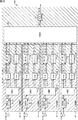
そして、ステップS102乃至S104において、リンクA及びリンクBの各映像データに対して、図6のステップS1乃至S3と同様の処理が行われる。その結果、リンクAの映像データから、図18に示されるCh1及びCh2のリンクAとリンクBの4つのHD-SDI相当のデータストリームが生成される。また、リンクBの映像データから、図19に示される3G-SDIのCh3及びCh4のリンクAとリンクBの4つのHD-SDI相当のデータストリームが生成される。 In steps S102 to S104, the same processing as steps S1 to S3 in FIG. 6 is performed on the video data of link A and link B. As a result, the four HD-SDI equivalent data streams of the links A and B of Ch1 and Ch2 shown in FIG. 18 are generated from the video data of link A. Further, four HD-SDI equivalent data streams of link A and link B of 3G-SDI Ch3 and Ch4 shown in FIG. 19 are generated from the video data of link B.
Ch1のリンクAのデータストリームは、図17のリンクAの映像データのベイヤ配列単位の偶数サンプルに含まれるGr、Gb、B、Rの各サンプルの画素データの上位8ビットが多重されたものである。換言すれば、このデータストリームは、リンクAの映像データのベイヤ配列単位の偶数サンプルを抽出することにより生成される映像データの各画素データの上位8ビットが多重されたものである。 The data stream of the link A of Ch1 is obtained by multiplexing the upper 8 bits of the pixel data of each sample of Gr, Gb, B, and R included in the even samples of the Bayer array unit of the video data of the link A in FIG. is there. In other words, this data stream is obtained by multiplexing the upper 8 bits of each pixel data of the video data generated by extracting the even samples of the Bayer array unit of the video data of the link A.
Ch1のリンクBのデータストリームは、図17のリンクAの映像データのベイヤ配列単位の奇数サンプルに含まれるGr、Gb、B、Rの各サンプルの画素データの上位8ビットが多重されたものである。換言すれば、このデータストリームは、リンクAの映像データのベイヤ配列単位の奇数サンプルを抽出することにより生成される映像データの各画素データの上位8ビットが多重されたものである。 The data stream of the link B of Ch1 is obtained by multiplexing the upper 8 bits of the pixel data of each sample of Gr, Gb, B, and R included in the odd sample of the Bayer array unit of the video data of the link A in FIG. is there. In other words, this data stream is obtained by multiplexing the upper 8 bits of each pixel data of the video data generated by extracting the odd samples of the Bayer array unit of the video data of link A.
Ch2のリンクAのデータストリームは、図17のリンクAの映像データのベイヤ配列単位の偶数サンプルに含まれるGr、Gb、B、Rの各サンプルの画素データの下位8ビットが多重されたものである。換言すれば、このデータストリームは、リンクAの映像データのベイヤ配列単位の偶数サンプルを抽出することにより生成される映像データの各画素データの下位8ビットが多重されたものである。 The data stream of the link A of Ch2 is obtained by multiplexing the lower 8 bits of the pixel data of each sample of Gr, Gb, B, and R included in the even sample of the Bayer array unit of the video data of the link A in FIG. is there. In other words, this data stream is obtained by multiplexing the lower 8 bits of each pixel data of the video data generated by extracting the even sample of the Bayer array unit of the video data of link A.
Ch2のリンクBのデータストリームは、図17のリンクAの映像データのベイヤ配列単位の奇数サンプルに含まれるGr、Gb、B、Rの各サンプルの画素データの下位8ビットが多重されたものである。換言すれば、このデータストリームは、リンクAの映像データのベイヤ配列単位の奇数サンプルを抽出することにより生成される映像データの各画素データの下位8ビットが多重されたものである。 The data stream of the link B of Ch2 is obtained by multiplexing the lower 8 bits of the pixel data of each sample of Gr, Gb, B, and R included in the odd sample of the Bayer array unit of the video data of the link A in FIG. is there. In other words, this data stream is obtained by multiplexing the lower 8 bits of each pixel data of the video data generated by extracting the odd samples of the Bayer array unit of the video data of link A.
Ch3のリンクAのデータストリームは、図17のリンクBの映像データのベイヤ配列単位の偶数サンプルに含まれるGr、Gb、B、Rの各サンプルの画素データの上位8ビットが多重されたものである。換言すれば、このデータストリームは、リンクBの映像データのベイヤ配列単位の偶数サンプルを抽出することにより生成される映像データの各画素データの上位8ビットが多重されたものである。 The data stream of link A of Ch3 is obtained by multiplexing the upper 8 bits of the pixel data of each sample of Gr, Gb, B, R included in the even sample of Bayer array unit of the video data of link B of FIG. is there. In other words, this data stream is obtained by multiplexing the upper 8 bits of each pixel data of the video data generated by extracting the even samples of the Bayer array unit of the video data of the link B.
Ch3のリンクBのデータストリームは、図17のリンクBの映像データのベイヤ配列単位の奇数サンプルに含まれるGr、Gb、B、Rの各サンプルの画素データの上位8ビットが多重されたものである。換言すれば、このデータストリームは、リンクBの映像データのベイヤ配列単位の奇数サンプルを抽出することにより生成される映像データの各画素データの上位8ビットが多重されたものである。 The link B data stream of Ch3 is obtained by multiplexing the upper 8 bits of the pixel data of each sample of Gr, Gb, B, and R included in odd-numbered samples of the Bayer array unit of the video data of link B in FIG. is there. In other words, this data stream is obtained by multiplexing the upper 8 bits of each pixel data of the video data generated by extracting the odd number samples of the Bayer arrangement unit of the video data of the link B.
Ch4のリンクAのデータストリームは、図17のリンクBの映像データのベイヤ配列単位の偶数サンプルに含まれるGr、Gb、B、Rの各サンプルの画素データの下位8ビットが多重されたものである。換言すれば、このデータストリームは、リンクBの映像データのベイヤ配列単位の偶数サンプルを抽出することにより生成される映像データの各画素データの下位8ビットが多重されたものである。 The data stream of link A of Ch4 is obtained by multiplexing the lower 8 bits of pixel data of each sample of Gr, Gb, B, and R included in the even sample of Bayer array unit of the video data of link B in FIG. is there. In other words, this data stream is obtained by multiplexing the lower 8 bits of each pixel data of the video data generated by extracting the even samples of the Bayer array unit of the video data of the link B.
Ch4のリンクBのデータストリームは、図17のリンクBの映像データのベイヤ配列単位の奇数サンプルに含まれるGr、Gb、B、Rの各サンプルの画素データの下位8ビットが多重されたものである。換言すれば、このデータストリームは、リンクBの映像データのベイヤ配列単位の奇数サンプルを抽出することにより生成される映像データの各画素データの下位8ビットが多重されたものである。 The data stream of the link B of Ch4 is obtained by multiplexing the lower 8 bits of the pixel data of each sample of Gr, Gb, B, and R included in the odd sample of the Bayer array unit of the video data of the link B in FIG. is there. In other words, this data stream is obtained by multiplexing the lower 8 bits of each pixel data of video data generated by extracting odd samples of Bayer array units of video data of link B.
なお、各画素データの各ビットは、図9を参照して上述した方法により、各データストリームに多重される。 Each bit of each pixel data is multiplexed into each data stream by the method described above with reference to FIG.
ステップS105において、多重部214−1乃至214−4は、3G-SDIのデータストリームを生成する。具体的には、多重部214−1は、図18の3G-SDIのCh1のリンクAとリンクBのデータストリームをワード単位でバイトインタリーブして多重化することにより、3G-SDIのCh1のデータストリームを生成する。このデータストリームは、図17のリンクAの映像データのGr、Gb、B、Rの各サンプルの画素データの上位8ビットが多重されたものである。多重部214−1は、生成した3G-SDIのCh1のデータストリームをスクランブル・P/S変換部215−1に供給する。 In step S105, the multiplexing units 214-1 to 214-4 generate 3G-SDI data streams. Specifically, the multiplexing unit 214-1 multiplexes the 3G-SDI Ch1 link A and link B data streams of FIG. 18 by byte interleaving in units of words and multiplexing the data streams. Create a stream. This data stream is obtained by multiplexing the upper 8 bits of the pixel data of the Gr, Gb, B, and R samples of the video data of link A in FIG. The multiplexing unit 214-1 supplies the generated 3G-SDI Ch1 data stream to the scramble / P / S conversion unit 215-1.
多重部214−2は、図18の3G-SDIのCh2のリンクAとリンクBのデータストリームをワード単位でバイトインタリーブして多重化することにより、3G-SDIのCh2のデータストリームを生成する。このデータストリームは、図17のリンクAの映像データのGr、Gb、B、Rの各サンプルの画素データの下位8ビットが多重されたものである。多重部214−2は、生成した3G-SDIのCh2のデータストリームをスクランブル・P/S変換部215−2に供給する。 The multiplexing unit 214-2 generates a 3G-SDI Ch2 data stream by byte-interleaving and multiplexing the 3G-SDI Ch2 link A and link B data streams of FIG. 18 in units of words. This data stream is obtained by multiplexing the lower 8 bits of the pixel data of the Gr, Gb, B, and R samples of the video data of link A in FIG. The multiplexing unit 214-2 supplies the generated 3G-SDI Ch2 data stream to the scramble / P / S conversion unit 215-2.
多重部214−3は、図19の3G-SDIのCh3のリンクAとリンクBのデータストリームをワード単位でバイトインタリーブして多重化することにより、3G-SDIのCh3のデータストリームを生成する。このデータストリームは、図17のリンクBの映像データのGr、Gb、B、Rの各サンプルの画素データの上位8ビットが多重されたものである。多重部214−3は、生成した3G-SDIのCh3のデータストリームをスクランブル・P/S変換部215−3に供給する。 The multiplexing unit 214-3 generates a 3G-SDI Ch3 data stream by byte interleaving and multiplexing the 3G-SDI Ch3 link A and link B data streams of FIG. 19 in units of words. This data stream is obtained by multiplexing the upper 8 bits of the pixel data of the Gr, Gb, B, and R samples of the video data of link B in FIG. The multiplexing unit 214-3 supplies the generated 3G-SDI Ch3 data stream to the scramble / P / S conversion unit 215-3.
多重部214−4は、図19の3G-SDIのCh4のリンクAとリンクBのデータストリームをワード単位でバイトインタリーブして多重化することにより、3G-SDIのCh4のデータストリームを生成する。このデータストリームは、図17のリンクBの映像データのGr、Gb、B、Rの各サンプルの画素データの下位8ビットが多重されたものである。多重部214−4は、生成した3G-SDIのCh4のデータストリームをスクランブル・P/S変換部215−4に供給する。 The multiplexing unit 214-4 generates a 3G-SDI Ch4 data stream by byte-interleaving and multiplexing the 3G-SDI Ch4 link A and link B data streams of FIG. 19 in units of words. This data stream is obtained by multiplexing the lower 8 bits of the pixel data of each sample of Gr, Gb, B, and R of the video data of link B in FIG. The multiplexing unit 214-4 supplies the generated 3G-SDI Ch4 data stream to the scramble / P / S conversion unit 215-4.
ステップS106において、スクランブル・P/S変換部215−1乃至215−4は、3G-SDIのデータストリームのスクランブル及びP/S変換を行う。すなわち、スクランブル・P/S変換部215−1乃至215−4は、図6のステップS5の処理と同様に、3G-SDIのCh1乃至Ch4のデータストリームのスクランブル及びP/S変換をそれぞれ行う。スクランブル・P/S変換部215−1乃至215−4は、処理後の3G-SDIのCh1乃至Ch4のデータストリームを送信制御部203に供給する。
In step S106, the scramble / P / S converters 215-1 to 215-4 scramble and P / S convert the 3G-SDI data stream. That is, the scramble / P / S converters 215-1 to 215-4 perform scramble and P / S conversion of 3G-SDI Ch1 to Ch4 data streams, respectively, in the same manner as the process of step S5 of FIG. The scramble / P / S conversion units 215-1 to 215-4 supply the 3G-SDI Ch1 to Ch4 data streams after processing to the
ステップS107において、送信制御部203は、3G-SDIのデータストリームを送信する。すなわち、送信制御部203は、Ch1乃至Ch4の4チャネルの3G-SDIのシリアル系列のデータストリームを送信することにより、RAWデータをCCU12bに送信する。
In step S107, the
その後、RAWデータ送信処理は終了する。 Thereafter, the RAW data transmission process ends.
[RAWデータ受信処理]
次に、図20のフローチャートを参照して、図16の放送用カメラ11bによるRAWデータ送信処理に対応して、CCU12bにより実行されるRAWデータ受信処理について説明する。
[RAW data reception processing]
Next, a RAW data reception process executed by the
ステップS151において、受信制御部251は、3G-SDIのデータストリームを受信する。すなわち、受信制御部251は、放送用カメラ11bから送信されてきた3G-SDIのCh1乃至Ch4のデータストリームを受信する。受信制御部251は、Ch1乃至Ch4のデータストリームをそれぞれS/P変換・デスクランブル部261−1乃至261−4に供給する。
In step S151, the
ステップS152において、S/P変換・デスクランブル部261−1乃至261−4は、3G-SDIのデータストリームのS/P変換及びデスクランブルを行う。具体的には、S/P変換・デスクランブル部261−1乃至261−4は、図11のステップS51と同様の処理により、それぞれCh1乃至Ch4のデータストリームのS/P変換及びデスクランブルを行う。そして、S/P変換・デスクランブル部261−1乃至261−4は、処理後のCh1乃至Ch4のデータストリームを分離部262−1乃至262−4に供給する。 In step S152, the S / P conversion / descrambling units 261-1 to 261-4 perform S / P conversion and descrambling of the 3G-SDI data stream. Specifically, the S / P conversion / descrambling units 261-1 to 261-4 perform S / P conversion and descrambling of the data streams of Ch1 to Ch4, respectively, by the same processing as step S51 of FIG. . Then, the S / P conversion / descramble units 261-1 to 261-4 supply the processed Ch1 to Ch4 data streams to the separation units 262-1 to 262-4.
ステップS153において、分離部262−1乃至262−4は、3G-SDIのデータストリームを分離する。具体的には、分離部262−1は、Ch1のデータストリームのワード同期検出を行い、さらにCh1のデータストリームを図18のリンクAとリンクBに分離し、再生部263に供給する。分離部262−2乃至262−4も同様に、それぞれCh2乃至Ch4のデータストリームを図18又は図19のリンクAとリンクBに分離し、再生部263に供給する。
In step S153, the demultiplexing units 262-1 to 262-4 demultiplex the 3G-SDI data stream. Specifically, the separation unit 262-1 performs word synchronization detection of the Ch1 data stream, further separates the Ch1 data stream into the link A and the link B in FIG. Similarly, the separation units 262-2 to 262-4 separate the Ch2 to Ch4 data streams into the link A and the link B in FIG. 18 or 19 and supply them to the
ステップS154において、再生部263は、RAWデータの再生を行う。具体的には、再生部263は、Ch1及びCh3のリンクA及びリンクBのデータストリームから、RAWデータのGr、Gb、B、Rの各サンプルの画素データの上位8ビットを抽出する。また、再生部263は、Ch2及びCh4のリンクA及びリンクBのデータストリームから、RAWデータのGr、Gb、B、Rの各サンプルの画素データの下位8ビットを抽出する。
In step S154, the
そして、再生部263は、抽出した各画素データの上位8ビット及び下位8ビットから、元の画素データを復元し、ベイヤ配列に従って並べ替えることにより、元の2フレーム分のRAWデータを復元する。そして、再生部263は、復元したRAWデータを映像処理部153に供給する。
Then, the reproducing
なお、このとき、RAWデータと異なる形式の映像データに変換して、映像処理部153に供給するようにしてもよい。
At this time, it may be converted into video data of a format different from the RAW data and supplied to the
その後、RAWデータ受信処理は終了する。 Thereafter, the RAW data reception process ends.
このようにして、3G-SDIのレベルBの規定に従って、例えば、既存の3G-SDI用のICや装置を用いて、47.95P-60Pの4Kのベイヤ配列のRAWデータを伝送することができる。また、Ch1及びCh3のデータストリームには、RAWデータの各画素データの上位8ビットが多重されている。従って、例えば、3G-SDI用の観測装置を用いて、Ch1又はCh3のデータストリームによりRAWデータの映像を目で見て確認することができる。さらに、各データストリームに付加されているCRCCを用いて、3G-SDIの観測装置により伝送系のエラーをモニタすることができる。 In this way, according to 3G-SDI level B regulations, for example, 47.95P-60P 4K Bayer array RAW data can be transmitted using existing 3G-SDI ICs and devices. In the data streams of Ch1 and Ch3, the upper 8 bits of each pixel data of RAW data are multiplexed. Therefore, for example, using an observation device for 3G-SDI, it is possible to visually check the video of RAW data using the Ch1 or Ch3 data stream. Furthermore, using the CRCC attached to each data stream, it is possible to monitor transmission system errors with a 3G-SDI observation device.
<6.第2の実施の形態の変形例>
以下、上述した第2の実施の形態の変形例について説明する。
<6. Modification of Second Embodiment>
Hereinafter, a modified example of the above-described second embodiment will be described.
[RAWデータの多重方法の変形例]
第1の実施の形態と同様に、RAWデータの各サンプルの画素データを3G-SDIの各チャネルに多重する方法として、図7、図12又は図13に示される方法を適用することができる。
[Variation of RAW data multiplexing method]
As in the first embodiment, the method shown in FIG. 7, FIG. 12 or FIG. 13 can be applied as a method of multiplexing pixel data of each sample of RAW data on each channel of 3G-SDI.
[HD-SDIを用いて伝送する場合]
以上の説明では、3G-SDIを用いてRAWデータを伝送する例を示したが、HD-SDIを用いて伝送することも可能である。具体的には、図18及び図19の3G-SDIのCh1乃至Ch4のリンクA及びリンクBのデータストリームは、それぞれHD-SDIのデータストリームと同様のデータ構造を有している。従って、各データストリームを個別にスクランブルし、P/S変換して伝送することにより、8チャネルのHD-SDIのデータストリームにより、47.95P-60Pの4KのRAWデータを伝送することが可能になる。
[When transmitting using HD-SDI]
In the above description, an example in which RAW data is transmitted using 3G-SDI has been described, but transmission using HD-SDI is also possible. Specifically, the 3G-SDI Ch1 to Ch4 link A and link B data streams in FIGS. 18 and 19 each have the same data structure as the HD-SDI data stream. Therefore, it is possible to transmit 47.95P-60P 4K RAW data by 8-channel HD-SDI data stream by individually scrambled each data stream, P / S converted and transmitted. .
この場合も、3G-SDIを用いた場合と同様に、例えば、既存のHD-SDI用のICや装置を用いて、47.95P-60Pの4Kのベイヤ配列のRAWデータを伝送することができる。また、HD-SDI用の観測装置を用いて、RAWデータの各画素データの上位8ビットが多重されているデータストリームによりRAWデータの映像を目で見て確認することができる。さらに、各データストリームに付加されているCRCCを用いて、HD-SDIの観測装置により伝送系のエラーをモニタすることができる。 In this case, as in the case of using 3G-SDI, for example, 47.95P-60P 4K Bayer array RAW data can be transmitted using an existing HD-SDI IC or device. Also, using an HD-SDI observation device, it is possible to visually check the video of the RAW data with a data stream in which the upper 8 bits of each pixel data of the RAW data are multiplexed. Furthermore, using the CRCC attached to each data stream, it is possible to monitor transmission system errors with an HD-SDI observation device.
[RAWデータの画素データが8ビット以下の場合の伝送方法]
RAWデータの画素データが8ビット以下の場合、図7、図12及び図13の5行目から8行目までのデータ列を伝送する必要がなくなる。従って、2チャネルの3G-SDIのデータストリーム、又は、4チャネルのHD-SDIのデータストリームでRAWデータを伝送することが可能である。
[Transmission method when pixel data of RAW data is 8 bits or less]
When the pixel data of the RAW data is 8 bits or less, it is not necessary to transmit the data string from the 5th line to the 8th line in FIGS. Accordingly, it is possible to transmit RAW data using a 2-
<7.第3の実施の形態>
次に、図21乃至図31を参照して、本技術の第3の実施の形態について説明する。本技術の第3の実施の形態は、ベイヤ配列のRAWデータを10.692Gbpsシリアルデジタルインターフェース(以下、10G-SDIとも称する)を用いて伝送できるようにするものである。
<7. Third Embodiment>
Next, a third embodiment of the present technology will be described with reference to FIGS. The third embodiment of the present technology enables transmission of Bayer array RAW data using a 10.692 Gbps serial digital interface (hereinafter also referred to as 10G-SDI).
[放送用カメラ11cの回路構成例]
図21は、図1の放送用カメラ11の第3の実施の形態である放送用カメラ11cの一部の機能の構成例を示すブロック図である。なお、図中、図14と対応する部分には同じ符号を付してあり、処理が同じ部分については、その説明は繰り返しになるため適宜省略する。
[Circuit Configuration Example of
FIG. 21 is a block diagram illustrating a configuration example of a part of a function of a
放送用カメラ11cは、撮像素子201、信号処理部202、信号処理部301及び送信制御部302を含むように構成される。
The
信号処理部301は、信号処理部202から供給される3G-SDIのCh1乃至Ch4のデータストリームから10G-SDIのデータストリームを生成して、生成した10G-SDIのデータストリームを送信制御部302に供給する。
The
送信制御部302は、10G-SDIのデータストリームのCCU12cへの送信を制御する。
The
[信号処理部301の構成例]
図22は、信号処理部301の構成例を示すブロック図である。信号処理部301は、データ処理部321−1乃至321−4、多重部322、及び、P/S変換部323を含むように構成される。また、データ処理部321−i(i=1,2,3,4)は、S/P変換・デスクランブル部331−i、分離部332−i、RAM333a−i,333b−i、8B/10Bエンコーダ334−i、及び、スクランブラ335−iを含むように構成される。さらに、データ処理部321−1は、8B/10Bエンコーダ334−5を含む。
[Configuration Example of Signal Processing Unit 301]
FIG. 22 is a block diagram illustrating a configuration example of the
S/P変換・デスクランブル部331−1乃至331−4は、それぞれ、信号処理部202から供給される3G-SDIのCh1乃至Ch4のデータストリームのS/P変換及びデスクランブルを行う。そして、S/P変換・デスクランブル部331−1乃至331−4は、それぞれ、処理後の3G-SDIのCh1乃至Ch4のデータストリームを分離部332−1乃至332−4に供給する。
The S / P conversion / descrambling units 331-1 to 331-4 respectively perform S / P conversion and descrambling of the 3G-SDI Ch1 to Ch4 data streams supplied from the
分離部332−1乃至332−4は、それぞれ、Ch1乃至Ch4のデータストリームを図18又は図19のリンクA及びリンクBの2チャネルのデータストリームに分離する。そして、分離部332−1乃至332−4は、それぞれ、3G-SDIのCh1乃至Ch4のリンクAのデータストリームをRAM333a−1乃至333a−4に記憶させる。また、分離部332−1乃至332−4は、それぞれ、3G-SDIのCh1乃至Ch4のリンクBのデータストリームをRAM333b−1乃至333b−4に記憶させる。
The demultiplexing units 332-1 to 332-4 demultiplex the Ch1 to Ch4 data streams into the two-channel data streams of the link A and the link B of FIG. The demultiplexers 332-1 to 332-4 store the 3G-SDI Ch1 to Ch4 link A data streams in the
8B/10Bエンコーダ334−1乃至334−4は、後述するように、それぞれ、RAM333a−1乃至333a−4に記憶されている3G-SDIのCh1乃至Ch4のリンクAのデータストリームを所定の単位ごとに8B/10B(8ビット/10ビット)変換する。そして、8B/10Bエンコーダ334−1乃至334−4は、それぞれ、処理の結果得られたデータブロックを多重部322に供給する。
As will be described later, the 8B / 10B encoders 334-1 through 334-4 process the 3G-SDI Ch1 through Ch4 link A data streams stored in the
8B/10Bエンコーダ334−5は、後述するように、RAM333b−1に記憶されている3G-SDIのCh1のリンクBのデータストリームの一部を所定の単位ごとに8B/10B変換し、処理の結果得られたデータブロックを多重部322に供給する。
As will be described later, the 8B / 10B encoder 334-5 performs 8B / 10B conversion of a part of the 3G-SDI Ch1 link B data stream stored in the
スクランブラ335−1乃至335−4は、後述するように、それぞれ、RAM333b−1乃至333b−4に記憶されている3G-SDIのCh1乃至Ch4のリンクBのデータストリームの一部を所定の単位ごとにスクランブルする。そして、スクランブラ335−1乃至335−4は、それぞれ、処理の結果得られたデータブロックを多重部322に供給する。
As will be described later, the scramblers 335-1 to 335-4 each of a part of the 3G-SDI Ch1 to Ch4 link B data stream stored in the
多重部322は、後述するように、8B/10Bエンコーダ334−1乃至334−5及びスクランブラ335−1乃至335−4から供給されるデータブロックを多重化することにより、10G-SDIのデータストリームを生成する。多重部322は、生成した10G-SDIのデータストリームをP/S変換部323に供給する。
As will be described later, the
P/S変換部323は、10G-SDIのデータストリームをP/S変換して、送信制御部302に供給する。
The P /
なお、信号処理部301のRAM333a−1乃至333a−4及びRAM333b−1乃至333b−4より前の部分は、148.5MHzのクロック信号に同期して動作する。一方、信号処理部301のRAM333a−1乃至333a−4及びRAM333b−1乃至333b−4より後の部分は、133.65MHzのクロック信号に同期して動作する。
Note that portions of the
また、以下、データ処理部321−1乃至321−4を個々に区別する必要がない場合、単に、データ処理部321と称する。さらに、以下、S/P変換・デスクランブル部331−1乃至331−4、分離部332−1乃至332−2、RAM333a−1乃至333a−4、RAM333b−1乃至333b−4、8B/10Bエンコーダ334−1乃至334−5、及び、スクランブラ335−1乃至335−4を個々に区別する必要がない場合、それぞれ、単にS/P変換・デスクランブル部331、分離部332、RAM333a、RAM333b、8B/10Bエンコーダ334、及び、スクランブラ335と称する。
Hereinafter, when it is not necessary to individually distinguish the data processing units 321-1 to 321-4, they are simply referred to as the
[CCU12cの回路構成例]
図23は、図1のCCU12の第3の実施の形態であるCCU12cの一部の機能の構成例を示すブロック図である。なお、図中、図15と対応する部分には同じ符号を付してあり、処理が同じ部分については、その説明は繰り返しになるため適宜省略する。
[
FIG. 23 is a block diagram illustrating a configuration example of a part of functions of the
CCU12cは、受信制御部351、信号処理部352、信号処理部252、及び、映像処理部153を含むように構成される。
The
受信制御部351は、各放送用カメラ11cからの10G-SDIのデータストリームの受信を制御する。受信制御部351は、受信した10G-SDIのデータストリームを信号処理部352に供給する。
The
信号処理部352は、10G-SDIのデータストリームを3G-SDIのCh1乃至Ch4のデータストリームに分離し、信号処理部252に供給する。
The
[信号処理部352の構成例]
図24は、信号処理部352の構成例を示すブロック図である。信号処理部352は、S/P変換部371、分離部372、及び、データ処理部373−1乃至373−4を含むように構成される。また、データ処理部373−i(i=1,2,3,4)は、8B/10Bデコーダ381−i、デスクランブラ382−i、RAM383a−i,383b−i、多重部384−i、及び、スクランブル・P/S変換部385−iを含むように構成される。さらに、データ処理部373−1は、8B/10Bデコーダ381−5を含む。
[Configuration Example of Signal Processing Unit 352]
FIG. 24 is a block diagram illustrating a configuration example of the
S/P変換部371は、10G-SDIのデータストリームをS/P変換して、分離部372に供給する。
The S /
分離部372は、図22の信号処理部301の多重部322と逆の処理により、10G-SDIのデータストリームを所定のデータブロックに分離する。そして、分離部372は、分離後のデータブロックを、8B/10Bデコーダ381−1乃至381−5及びデスクランブラ382−1乃至382−4に供給する。
The
8B/10Bデコーダ381−1乃至381−4は、後述するように、それぞれ、分離部372から供給されるデータブロックを10ビット/8ビット(10B/8B)変換し、RAM383a−1乃至383a−4に記憶させる。
As will be described later, the 8B / 10B decoders 381-1 to 381-4 respectively convert the data blocks supplied from the
8B/10Bデコーダ381−5は、後述するように、分離部372から供給されるデータブロックを10B/8B変換し、RAM383b−1に記憶させる。
As will be described later, the 8B / 10B decoder 381-5 performs 10B / 8B conversion on the data block supplied from the
デスクランブラ382−1乃至382−4は、後述するように、それぞれ、分離部372から供給されるデータブロックをデスクランブルし、RAM383b−1乃至383b−4に記憶させる。
As described later, the descramblers 382-1 to 382-4 descramble the data blocks supplied from the
多重部384−1乃至384−4は、後述するように、それぞれ、RAM383a−1乃至383a−4及びRAM383b−1乃至383b−4に記憶されているデータブロックを用いて、3G-SDIのCh1乃至Ch4のデータストリームを生成する。そして、多重部384−1乃至384−4は、それぞれ、生成した3G-SDIのCh1乃至Ch4のデータストリームをスクランブル・P/S変換部385−1乃至385−4に供給する。
As will be described later, the multiplexing units 384-1 to 384-4 use the data blocks stored in the RAMs 383 a-1 to 383 a-4 and the
スクランブル・P/S変換部385−1乃至385−4は、それぞれ、3G-SDIのCh1乃至Ch4のデータストリームのスクランブル及びP/S変換を行う。そして、スクランブル・P/S変換部385−1乃至385−4は、それぞれ、処理後の3G-SDIのCh1乃至Ch4のデータストリームを信号処理部252に供給する。
The scramble / P / S converters 385-1 to 385-4 perform scramble and P / S conversion of 3G-SDI Ch1 to Ch4 data streams, respectively. The scramble / P / S converters 385-1 to 385-4 supply the processed 3G-SDI Ch1 to Ch4 data streams to the
なお、信号処理部352のRAM383a−1乃至383a−4及びRAM383b−1乃至383b−4より前の部分は、133.65MHzのクロック信号に同期して動作する。一方、信号処理部352のRAM383a−1乃至383a−4及びRAM383b−1乃至383b−4より後の部分は、148.5MHzのクロック信号に同期して動作する。
Note that portions of the
また、以下、データ処理部373−1乃至373−4を個々に区別する必要がない場合、単に、データ処理部373と称する。さらに、以下、8B/10Bデコーダ381−1乃至381−5、デスクランブラ382−1乃至382−4、RAM383a−1乃至383a−4、RAM383b−1乃至383b−4、多重部384−1乃至384−4、及び、スクランブル・P/S変換部385−1乃至385−4を個々に区別する必要がない場合、単に、8B/10Bデコーダ381、デスクランブラ382、RAM383a、RAM383b、多重部384、及び、スクランブル・P/S変換部385と称する。
Hereinafter, when it is not necessary to individually distinguish the data processing units 373-1 to 373-4, they are simply referred to as the data processing unit 373. Further, hereinafter, 8B / 10B decoders 381-1 to 381-5, descramblers 382-1 to 382-4,
[RAWデータ送信処理]
次に、図25のフローチャートを参照して、放送用カメラ11cにより実行されるRAWデータ送信処理について説明する。なお、この処理は2フレーム分のRAWデータを送信する場合の処理を示しており、3フレーム以上のRAWデータを送信する場合には、この処理が繰り返し実行される。
[RAW data transmission processing]
Next, the RAW data transmission process executed by the
ステップS201乃至S206において、図16のステップS101乃至S106と同様の処理が実行される。これにより、RAWデータが3G-SDIのCh1乃至Ch4のデータストリームに多重され、各チャネルのデータストリームが信号処理部301のS/P変換・デスクランブル部331−1乃至331−4に供給される。
In steps S201 to S206, processing similar to that in steps S101 to S106 in FIG. 16 is executed. As a result, the RAW data is multiplexed into 3G-SDI Ch1 to Ch4 data streams, and the data stream of each channel is supplied to the S / P conversion / descrambling units 331-1 to 331-4 of the
ステップS207において、S/P変換・デスクランブル部331−1乃至331−4は、図20のステップS152と同様の処理により、3G-SDIのCh1乃至Ch4のデータストリームのS/P変換及びデスクランブルをそれぞれ行う。S/P変換・デスクランブル部331−1乃至331−4は、処理後のCh1乃至Ch4のデータストリームをそれぞれ分離部332−1乃至332−4に供給する。 In step S207, the S / P conversion / descrambling units 331-1 to 331-4 perform S / P conversion and descrambling of the 3G-SDI Ch1 to Ch4 data streams by the same processing as in step S152 of FIG. Do each. The S / P conversion / descrambling units 331-1 to 331-4 supply the processed Ch1 to Ch4 data streams to the demultiplexing units 332-1 to 332-4, respectively.
ステップS208において、分離部332−1乃至332−4は、図20のステップS153と同様の処理により、3G-SDIのCh1乃至Ch4のデータストリームを図18及び図19に示されるリンクAとリンクBのデータストリームに分離する。そして、Ch1乃至Ch4のリンクAのデータストリームは、RAM333a−1に記憶され、Ch1乃至Ch4のリンクBのデータストリームは、RAM333b−1に記憶される。
In step S208, the demultiplexing units 332-1 to 332-4 process the 3G-SDI Ch1 to Ch4 data streams in the links A and B shown in FIGS. To separate data streams. The data stream of link A from Ch1 to Ch4 is stored in the
なお、以下、3G-SDIのCh1のリンクAのデータストリームを(HD-SDIの)Ch1のデータストリームとも称し、3G-SDIのCh1のリンクBのデータストリームを(HD-SDIの)Ch2のデータストリームとも称する。また、以下、3G-SDIのCh2のリンクAのデータストリームを(HD-SDIの)Ch3のデータストリームとも称し、3G-SDIのCh2のリンクBのデータストリームを(HD-SDIの)Ch4のデータストリームとも称する。さらに、以下、3G-SDIのCh3のリンクAのデータストリームを(HD-SDIの)Ch5のデータストリームとも称し、3G-SDIのCh3のリンクBのデータストリームを(HD-SDIの)Ch6のデータストリームとも称する。また、以下、3G-SDIのCh4のリンクAのデータストリームを(HD-SDIの)Ch7のデータストリームとも称し、3G-SDIのCh4のリンクBのデータストリームを(HD-SDIの)Ch8のデータストリームとも称する。 In the following, the 3G-SDI Ch1 link A data stream is also referred to as the (HD-SDI) Ch1 data stream, and the 3G-SDI Ch1 link B data stream is the (HD-SDI) Ch2 data stream. Also called a stream. In the following, the 3G-SDI Ch2 link A data stream is also called the (HD-SDI) Ch3 data stream, and the 3G-SDI Ch2 link B data stream is the (HD-SDI) Ch4 data stream. Also called a stream. In the following, the 3G-SDI Ch3 link A data stream is also called the (HD-SDI) Ch5 data stream, and the 3G-SDI Ch3 link B data stream is the (HD-SDI) Ch6 data. Also called a stream. In the following, the 3G-SDI Ch4 link A data stream is also referred to as the (HD-SDI) Ch7 data stream, and the 3G-SDI Ch4 link B data stream is the (HD-SDI) Ch8 data. Also called a stream.
ステップS209において、信号処理部301は、10G-SDIのデータストリームを生成する。まず、8B/10Bエンコーダ334−1は、RAM333a−1に記憶されているCh1のデータストリームのSAVの最初のワードからEAV/LN/CRCの最後のワードまでの領域から8ビット単位でデータを抜き出す。
In step S209, the
具体的には、Ch1のデータストリームの有効映像データ領域(H-Active)からは、RAWデータの画素データの上位8ビットが多重されている上位6ビット(B9−B4)と下位2ビット(B1−B0)の計8ビットのデータが抜き出される。また、SAV及びEAVの3FFh,000h,000h,XYZは、下位2ビットがリザーブ=0又は1であるので、10ビットのデータのうちの上位8ビットが抜き出される。 Specifically, from the effective video data area (H-Active) of the data stream of Ch1, the upper 6 bits (B9-B4) in which the upper 8 bits of the pixel data of the RAW data are multiplexed and the lower 2 bits (B1) -B0), a total of 8 bits of data is extracted. In addition, since the lower 2 bits of the SAV and EAV 3FFh, 000h, 000h, XYZ are reserved = 0 or 1, the upper 8 bits of the 10-bit data are extracted.
EAVの後のLN及びCRCについては、以下の手順で、図26に示されるようにデータの抽出及び整列が行われ、1ワード(10ビット)単位のデータが、1バイト(8ビット)単位のデータに変換される。なお、CLNはCチャネルのLNを表し、YLNはYチャネルのLNを表し、CCRはCチャネルのCRCを表し、YCRはYチャネルのCRCを表す。 For LN and CRC after EAV, data is extracted and arranged as shown in FIG. 26 according to the following procedure, and data in units of 1 word (10 bits) is converted into units of 1 byte (8 bits). Converted to data. CLN represents C channel LN, YLN represents Y channel LN, CCR represents C channel CRC, and YCR represents Y channel CRC.
・CLN0の下位8ビットであるCLN0:0-7(第0ビットから第7ビットを表す。以下、同様に表記する。)
・CLN0:8-9、YLN0:2-7
・CLN1:0-7
・CLN0:8-9、YCR0:0-5
・CCR:0-7
・CCR:8-9、YCR0:6-8、YCR1:0-2
・CCR1:0-7
・CCR1:8-9、YCR1:3-8
CLN0: 0-7, which is the lower 8 bits of CLN0 (represents 0th to 7th bits, hereinafter the same)
・ CLN0: 8-9, YLN0: 2-7
・ CLN1: 0-7
・ CLN0: 8-9, YCR0: 0-5
・ CCR: 0-7
・ CCR: 8-9, YCR0: 6-8, YCR1: 0-2
・ CCR1: 0-7
・ CCR1: 8-9, YCR1: 3-8
なお、CLNとYLNは同じデータであるため、YLNは基本的に削除され、多重されない。従って、YLN0:2-7はCLN0:2-7から判明するため、YLN0:2-7の代わりに、オール1のようなデータを埋め込んでもよい。また、CRCの第9ビットは第8ビットの反転ビットなので、削除され多重されない。また、CCRとYCRには、RAWデータをデータストリームに多重した後に計算されたデータが設定される。 Since CLN and YLN are the same data, YLN is basically deleted and not multiplexed. Therefore, since YLN0: 2-7 is determined from CLN0: 2-7, data such as all 1 may be embedded instead of YLN0: 2-7. Also, since the ninth bit of CRC is an inverted bit of the eighth bit, it is deleted and not multiplexed. In CCR and YCR, data calculated after multiplexing RAW data into a data stream is set.
また、8B/10Bエンコーダ334−1は、図27に示されるように、SAVの最初の2バイト(16ビット)を2バイトのK28.5に置き換える。置き換えられた部分は、8バイト/10バイト変換符号のワード同期信号として用いられる。なお、この置き換えは、Ch1のデータストリームに対してのみ行われる。 Further, as shown in FIG. 27, the 8B / 10B encoder 334-1 replaces the first 2 bytes (16 bits) of the SAV with 2 bytes of K28.5. The replaced portion is used as a word synchronization signal of an 8-byte / 10-byte conversion code. This replacement is performed only for the data stream of Ch1.
そして、8B/10Bエンコーダ334−1は、Ch1のデータストリームのSAVからEAV/LN/CRCまでの領域(以下、SAV-EAV領域と称する)から抜き出した8ビット単位のデータ列を、順次32ビット(8ビット×4サンプル)単位で8B/10B変換し、40ビットのデータブロックを生成し、多重部322に供給する。
The 8B / 10B encoder 334-1 then sequentially converts the 8-bit unit data string extracted from the area from the SAV to the EAV / LN / CRC of the Ch1 data stream (hereinafter referred to as the SAV-EAV area) into 32 bits. 8B / 10B conversion is performed in units of (8 bits × 4 samples), a 40-bit data block is generated, and supplied to the
また、8B/10Bエンコーダ334−1は、Ch1のデータストリームの水平補助データ領域から40ビット(10ビット×4サンプル)単位でデータを抜き出し、8B/10B変換により50ビットのデータブロックを生成し、多重部322に供給する。
The 8B / 10B encoder 334-1 extracts data in units of 40 bits (10 bits × 4 samples) from the horizontal auxiliary data area of the data stream of Ch1, and generates a 50-bit data block by 8B / 10B conversion. This is supplied to the
同様に、8B/10Bエンコーダ334−2は、Ch3のデータストリームのSAV-EAV領域から抜き出した8ビット単位のデータ列を、順次32ビット(8ビット×4サンプル)単位で8B/10B変換し、40ビットのデータブロックを生成し、多重部322に供給する。また、8B/10Bエンコーダ334−2は、Ch3のデータストリームの水平補助データ領域から40ビット(10ビット×4サンプル)単位でデータを抜き出し、8B/10B変換により50ビットのデータブロックを生成し、多重部322に供給する。
Similarly, the 8B / 10B encoder 334-2 sequentially converts the 8-bit unit data string extracted from the SAV-EAV area of the Ch3 data stream into 8B / 10B units in units of 32 bits (8 bits × 4 samples), A 40-bit data block is generated and supplied to the
8B/10Bエンコーダ334−3は、Ch5のデータストリームのSAV-EAV領域から抜き出した8ビット単位のデータ列を、順次32ビット(8ビット×4サンプル)単位で8B/10B変換し、40ビットのデータブロックを生成し、多重部322に供給する。また、8B/10Bエンコーダ334−3は、Ch5のデータストリームの水平補助データ領域から40ビット(10ビット×4サンプル)単位でデータを抜き出し、8B/10B変換により50ビットのデータブロックを生成し、多重部322に供給する。
The 8B / 10B encoder 334-3 sequentially converts the 8-bit unit data string extracted from the SAV-EAV area of the Ch5 data stream into 8B / 10B units in units of 32 bits (8 bits × 4 samples), and generates 40-bit units. A data block is generated and supplied to the
8B/10Bエンコーダ334−4は、Ch7のデータストリームのSAV-EAV領域から抜き出した8ビット単位のデータ列を、順次32ビット(8ビット×4サンプル)単位で8B/10B変換し、40ビットのデータブロックを生成し、多重部322に供給する。また、8B/10Bエンコーダ334−3は、Ch7のデータストリームの水平補助データ領域から40ビット(10ビット×4サンプル)単位でデータを抜き出し、8B/10B変換して50ビットのデータブロックを生成し、多重部322に供給する。
The 8B / 10B encoder 334-4 sequentially converts the 8-bit unit data sequence extracted from the SAV-EAV area of the Ch7 data stream into 8B / 10B units in units of 32 bits (8 bits × 4 samples), and generates 40 bits. A data block is generated and supplied to the
また、スクランブラ335−1は、8B/10Bエンコーダ334−1と同様に、Ch2のデータストリームのSAV-EAV領域から8ビット単位でデータを抜き出す。そして、スクランブラ335−1は、抜き出したデータを順次32ビット単位でスクランブルして、32ビットのデータブロックを生成し、多重部322に供給する。
Similarly to the 8B / 10B encoder 334-1, the scrambler 335-1 extracts data in units of 8 bits from the SAV-EAV area of the Ch2 data stream. Then, the scrambler 335-1 sequentially scrambles the extracted data in units of 32 bits, generates a 32-bit data block, and supplies the data block to the
同様に、スクランブラ335−2は、Ch4のデータストリームのSAV-EAV領域から8ビット単位でデータを抜き出す。そして、スクランブラ335−2は、抜き出したデータを順次32ビット単位でスクランブルして、32ビットのデータブロックを生成し、多重部322に供給する。
Similarly, the scrambler 335-2 extracts data in 8-bit units from the SAV-EAV area of the data stream of Ch4. Then, the scrambler 335-2 sequentially scrambles the extracted data in units of 32 bits, generates a 32-bit data block, and supplies the data block to the
スクランブラ335−3は、Ch6のデータストリームのSAV-EAV領域から8ビット単位でデータを抜き出す。そして、スクランブラ335−3は、抜き出したデータを順次32ビット単位でスクランブルして、32ビットのデータブロックを生成し、多重部322に供給する。
The scrambler 335-3 extracts data in 8-bit units from the SAV-EAV area of the Ch6 data stream. The scrambler 335-3 scrambles the extracted data sequentially in units of 32 bits, generates a 32-bit data block, and supplies the data block to the
スクランブラ335−4は、Ch8のデータストリームのSAV-EAV領域から8ビット単位でデータを抜き出す。そして、スクランブラ335−4は、抜き出したデータを順次32ビット単位でスクランブルして、32ビットのデータブロックを生成し、多重部322に供給する。
The scrambler 335-4 extracts data in 8-bit units from the SAV-EAV area of the Ch8 data stream. The scrambler 335-4 scrambles the extracted data sequentially in units of 32 bits, generates a 32-bit data block, and supplies the data block to the
また、8B/10Bエンコーダ334−5は、Ch2のデータストリームの水平補助データ領域から40ビット(10ビット×4サンプル)単位でデータを抜き出し、8B/10B変換して50ビットのデータブロックを生成し、多重部322に供給する。
The 8B / 10B encoder 334-5 extracts data from the horizontal auxiliary data area of the Ch2 data stream in units of 40 bits (10 bits × 4 samples), and performs 8B / 10B conversion to generate a 50-bit data block. , And supplied to the
多重部322は、以上のようにしてデータ処理部321−1乃至321−4から供給されるデータブロックを、図28の右側及び図29に示されるように多重化することにより、10G-SDIのデータストリームを生成する。なお、図29は、10G-SDIのデータストリームの1ライン期間のデータの構成例を示している。
The
すなわち、多重部322は、Ch1乃至Ch8のデータストリームのSAV-EAV領域から生成された40ビット又は32ビットのデータブロックを、Ch1,Ch2,Ch3,Ch4,Ch5,Ch6,Ch7,Ch8,Ch1,Ch2・・・の順に1ブロックずつ多重する。これにより、10G-SDIのデータストリームのSAV、有効映像データ領域、EAV/LN/CRCの領域が生成される。
That is, the
また、多重部322は、Ch1、Ch2、Ch3、Ch5、Ch7のデータストリームの水平補助データ領域から生成された50ビットのデータブロックを、Ch1,Ch2,Ch3,Ch5,Ch7,Ch1,Ch2・・・の順に1ブロックずつ多重する。これにより、10G-SDIのデータストリームの水平補助データ領域が生成される。
Further, the
さらに、多重部322は、1ラインの周期を揃えるために、水平補助データ領域の後に8B/10B符号のD0.0からなる付加データを多重する。
Further, the
そして、多重部322は、生成した10G-SDIのデータストリームをP/S変換部323に供給する。
Then, the
ステップS210において、P/S変換部323は、10G-SDIのデータストリームのP/S変換を行う。すなわち、P/S変換部323は、多重部322から供給される10G-SDIのデータストリームをP/S変換し、送信制御部302に供給する。
In step S210, the P /
ステップS211において、送信制御部302は、10G-SDIのデータストリームを送信する。すなわち、送信制御部302は、10G-SDIのシリアル系列のデータストリームを送信することにより、RAWデータをCCU12cに送信する。
In step S211, the
図30は、第3の実施の形態の10G-SDIのデータストリームの1ラインあたりの全ワード数、有効映像データ領域のデータ数、水平補助データ領域及びSAV/EAV/LN/CRCのデータ数、付加データのデータ数を、伝送するRAWデータのフォーマット及びフレームレート毎に示している。 FIG. 30 shows the total number of words per line of the 10G-SDI data stream of the third embodiment, the number of valid video data areas, the number of horizontal auxiliary data areas and the number of SAV / EAV / LN / CRC data, The number of additional data is shown for each RAW data format and frame rate to be transmitted.
[RAWデータ受信処理]
次に、図31のフローチャートを参照して、図25の放送用カメラ11cによるRAWデータ送信処理に対応して、CCU12cにより実行されるRAWデータ受信処理について説明する。
[RAW data reception processing]
Next, the RAW data reception process executed by the
ステップS251において、受信制御部351は、放送用カメラ11cから送信されてきた10G-SDIのデータストリームを受信し、S/P変換部371に供給する。
In step S251, the
ステップS252において、S/P変換部371は、10G-SDIのデータストリームをS/P変換し、分離部372に供給する。
In step S <b> 252, the S /
ステップS253において、信号処理部352は、10G-SDIのデータストリームを3G-SDIのデータストリームに分離する。具体的には、分離部372は、放送用カメラ11の多重部322と逆の処理により、10G-SDIのデータストリームを各データブロックに分離する。そして、分離部372は、HD-SDIのCh1,Ch3,Ch5,Ch7のデータストリームのSAV-EAV領域のデータからなる40ビットのデータブロックを、8B/10Bデコーダ381−1乃至381−4にそれぞれ供給する。また、分離部372は、HD-SDIのCh2,Ch4,Ch6,Ch8のデータストリームのSAV-EAV領域のデータからなる32ビットのデータブロックを、デスクランブラ382−1乃至382−4にそれぞれ供給する。
In step S253, the
さらに、分離部372は、HD-SDIのCh1,Ch3,Ch5,Ch7のデータストリームの水平補助データ領域のデータからなる50ビットのデータブロックを、8B/10Bデコーダ381−1乃至381−4にそれぞれ供給する。また、分離部372は、HD-SDIのCh2のデータストリームの水平補助データ領域のデータからなる50ビットのデータブロックを、8B/10Bデコーダ381−5に供給する。
Further, the
8B/10Bデコーダ381−1乃至381−4は、分離部372から供給されるデータブロックを10B/8B変換し、RAM383a−1乃至383a−4に記憶させる。
The 8B / 10B decoders 381-1 to 381-4
デスクランブラ382−1乃至382−4は、分離部372から供給されるデータブロックをデスクランブルし、RAM383b−1乃至383b−4に記憶させる。
The descramblers 382-1 to 382-4 descramble the data blocks supplied from the
8B/10Bデコーダ381−5は、分離部372から供給されるデータブロックを10B/8B変換し、RAM383b−1に記憶させる。
The 8B / 10B decoder 381-5 performs 10B / 8B conversion on the data block supplied from the
多重部384−1は、放送用カメラ11cの分離部332−1と逆の処理により、RAM383a−1及びRAM383b−1に記憶されているデータブロックを用いて、3G-SDIのCh1のデータストリームを生成する。多重部384−1は、生成した3G-SDIのCh1のデータストリームをスクランブル・P/S変換部385−1に供給する。
The multiplexing unit 384-1 uses the data block stored in the RAM 383 a-1 and the
多重部384−2は、放送用カメラ11cの分離部332−2と逆の処理により、RAM383a−2及びRAM383b−2に記憶されているデータブロックを用いて、3G-SDIのCh2のデータストリームを生成する。多重部384−2は、生成した3G-SDIのCh2のデータストリームをスクランブル・P/S変換部385−2に供給する。
The multiplexing unit 384-2 performs the reverse processing to the separation unit 332-2 of the
多重部384−3は、放送用カメラ11cの分離部332−3と逆の処理により、RAM383a−3及びRAM383b−3に記憶されているデータブロックを用いて、3G-SDIのCh3のデータストリームを生成する。多重部384−3は、生成した3G-SDIのCh3のデータストリームをスクランブル・P/S変換部385−3に供給する。
The multiplexing unit 384-3 performs processing reverse to that of the separation unit 332-3 of the
多重部384−4は、放送用カメラ11cの分離部332−4と逆の処理により、RAM383a−4及びRAM383b−4に記憶されているデータブロックを用いて、3G-SDIのCh4のデータストリームを生成する。多重部384−4は、生成した3G-SDIのCh4のデータストリームをスクランブル・P/S変換部385−4に供給する。
The multiplexing unit 384-4 performs the reverse processing to the separation unit 332-4 of the
ステップS254において、スクランブル・P/S変換部385−1乃至385−4は、3G-SDIのデータストリームのスクランブル及びP/S変換を行う。すなわち、スクランブル・P/S変換部385−1乃至385−4は、図6のステップS5の処理と同様に、3G-SDIのCh1乃至Ch4のデータストリームのスクランブル及びP/S変換をそれぞれ行う。スクランブル・P/S変換部385−1乃至385−4は、処理後の3G-SDIのCh1乃至Ch4のデータストリームを、信号処理部252のS/P変換・デスクランブル部261−1乃至261−4に供給する。
In step S254, the scramble / P / S converters 385-1 to 385-4 scramble and P / S convert the 3G-SDI data stream. That is, the scramble / P / S converters 385-1 to 385-4 perform scramble and P / S conversion of 3G-SDI Ch1 to Ch4 data streams, respectively, in the same manner as the process of step S5 of FIG. The scramble / P / S converters 385-1 to 385-4 convert the processed 3G-SDI Ch1 to Ch4 data streams into S / P conversion / descramble units 261-1 to 261- 1 of the
その後、ステップS255乃至S257において、図20のステップS152乃至S154と同様の処理が実行される。これにより、元の2フレーム分のRAWデータが復元され、映像処理部153に供給される。
Thereafter, in steps S255 to S257, processing similar to that in steps S152 to S154 in FIG. 20 is executed. Thereby, the original two frames of RAW data are restored and supplied to the
その後、RAWデータ受信処理は終了する。 Thereafter, the RAW data reception process ends.
このようにして、10G-SDIを用いて、47.95P-60Pの4Kのベイヤ配列のRAWデータを伝送することができる。 In this way, 47.95P-60P 4K Bayer array RAW data can be transmitted using 10G-SDI.
<8.第3の実施の形態の変形例>
以下、上述した第3の実施の形態の変形例について説明する。
<8. Modification of Third Embodiment>
Hereinafter, a modification of the above-described third embodiment will be described.
例えば、放送用カメラ11cの信号処理部202から信号処理部301に、スクランブル及びP/S変換を行う前の3G-SDIのデータストリームを供給するようにすることも可能である。これにより、信号処理部202のスクランブル・P/S変換部215−1乃至215−4を削除して、スクランブル及びP/S変換を省略したり、信号処理部301のS/P変換・デスクランブル部331−1乃至331−4を削除して、S/P変換及びデスクランブルの処理を省略したりすることが可能になる。
For example, a 3G-SDI data stream before being scrambled and P / S converted may be supplied from the
さらに、例えば、放送用カメラ11cの信号処理部202から信号処理部301に、3G-SDIのデータストリームに多重化する前のHD-SDIのデータストリームを供給するようにすることも可能である。これにより、信号処理部202の多重部214−1乃至214−4を削除してHD-SDIから3G-SDIへの多重化処理を省略したり、信号処理部301の分離部332−1乃至332−4を削除して3G-SDIからHD-SDIへの分離処理を省略したりすることが可能になる。
Further, for example, the HD-SDI data stream before being multiplexed with the 3G-SDI data stream can be supplied from the
さらに、例えば、CCU12cの信号処理部352から信号処理部252に、スクランブル及びP/S変換を行う前の3G-SDIのデータストリームを供給するようにすることも可能である。これにより、信号処理部352のスクランブル及びP/S変換、並びに、信号処理部252のS/P変換及びデスクランブルの処理を省略することが可能になる。
Further, for example, a 3G-SDI data stream before being scrambled and P / S converted may be supplied from the
また、例えば、CCU12cの信号処理部352から信号処理部252に、3G-SDIのデータストリームに多重化する前のHD-SDIのデータストリームを供給するようにしてもよい。これにより、信号処理部352のHD-SDIから3G-SDIへの多重化処理、並びに、信号処理部252の3G-SDIからHD-SDIへの分離処理を省略することが可能になる。
Further, for example, the HD-SDI data stream before being multiplexed with the 3G-SDI data stream may be supplied from the
<9.第4の実施の形態>
次に、図32乃至図38を参照して、本技術の第4の実施の形態について説明する。
<9. Fourth Embodiment>
Next, a fourth embodiment of the present technology will be described with reference to FIGS. 32 to 38.
上述した第3の実施の形態は、RAWデータを8チャネルのHD-SDI(4チャネルの3G-SDI)のデータストリームに多重したものを1チャネルの10G-SDIのデータストリームに変換して伝送する技術に関するものであった。これに対して、第4の実施の形態は、8チャネルのHD-SDIのデータストリームのうち7チャネルにRAWデータを多重し、残りの1チャネル(以下、トランクラインとも称する)にRAWデータとは別のデータを多重したものを1チャネルの10G-SDIのデータストリームに変換して伝送するものである。
In the third embodiment described above, RAW data multiplexed into an 8-channel HD-SDI (4-
[放送用カメラ11dの回路構成例]
図32は、図1の放送用カメラ11の第4の実施の形態である放送用カメラ11dの一部の機能の構成例を示すブロック図である。なお、図中、図21と対応する部分には同じ符号を付してあり、処理が同じ部分については、その説明は繰り返しになるため適宜省略する。
[Circuit Configuration Example of
FIG. 32 is a block diagram illustrating a configuration example of a part of a function of a
放送用カメラ11dは、図21の放送用カメラ11cと比較して、信号処理部301の代わりに信号処理部401が設けられている点が異なる。
The
信号処理部401は、信号処理部202から供給される3G-SDIのCh1乃至Ch4のデータストリームから10G-SDIのデータストリームを生成して、生成した10G-SDIのデータストリームを送信制御部302に供給する。
The
[信号処理部401の構成例]
図33は、信号処理部401の構成例を示すブロック図である。なお、図中、図22と対応する部分には同じ符号を付してあり、処理が同じ部分については、その説明は繰り返しになるため適宜省略する。
[Configuration Example of Signal Processing Unit 401]
FIG. 33 is a block diagram illustrating a configuration example of the
信号処理部401は、図22の信号処理部301と比較して、データ処理部321−1、データ処理部321−4、及び、多重部322の代わりに、それぞれデータ処理部421−1、データ処理部421−2、及び、多重部422が設けられている点が異なる。
Compared with the
データ処理部421−1は、信号処理部301のデータ処理部321−1と比較して、8B/10Bエンコーダ334−5が削除されている点が異なる。
The data processing unit 421-1 is different from the data processing unit 321-1 of the
データ処理部421−2は、信号処理部301のデータ処理部321−4と比較して、8B/10Bエンコーダ334−4の代わりに、8B/10Bエンコーダ431が設けられている点が異なる。8B/10Bエンコーダ431は、RAM333a−4に記憶されているCh7のデータストリームを所定の単位ごとに8B/10B(8ビット/10ビット)変換し、得られたデータブロックを多重部422に供給する。
The data processing unit 421-2 is different from the data processing unit 321-4 of the
多重部422は、8B/10Bエンコーダ334−1乃至334−3、8B/10Bエンコーダ431、及び、スクランブラ335−1乃至335−4から供給されるデータブロックを多重化することにより、10G-SDIのデータストリームを生成する。多重部422は、生成した10G-SDIのデータストリームをP/S変換部323に供給する。
The
[CCU12dの回路構成例]
図34は、図1のCCU12の第4の実施の形態であるCCU12dの一部の機能の構成例を示すブロック図である。なお、図中、図23と対応する部分には同じ符号を付してあり、処理が同じ部分については、その説明は繰り返しになるため適宜省略する。
[
FIG. 34 is a block diagram illustrating a configuration example of a part of functions of the
CCU12dは、図23のCCU12cと比較して、信号処理部352の代わりに信号処理部451が設けられている点が異なる。
The
信号処理部451は、10G-SDIのデータストリームを3G-SDIのCh1乃至Ch4のデータストリームに分離し、信号処理部252に供給する。
The
[信号処理部451の構成例]
図35は、信号処理部451の構成例を示すブロック図である。なお、図中、図24と対応する部分には同じ符号を付してあり、処理が同じ部分については、その説明は繰り返しになるため適宜省略する。
[Configuration Example of Signal Processing Unit 451]
FIG. 35 is a block diagram illustrating a configuration example of the
信号処理部451は、図24の信号処理部352と比較して、分離部372、データ処理部373−1、及び、データ処理部373−4、及びの代わりに、それぞれ分離部471、データ処理部472−1、及び、データ処理部472−2が設けられている点が異なる。
The
分離部471は、図33の信号処理部401の多重部422と逆の処理により、10G-SDIのデータストリームを所定のデータブロックに分離する。そして、分離部471は、分離後のデータブロックを、8B/10Bデコーダ381−1乃至381−3、8B/10Bデコーダ481及びデスクランブラ382−1乃至382−4に供給する。
The separation unit 471 separates the 10G-SDI data stream into predetermined data blocks by a process reverse to the
データ処理部472−1は、信号処理部352のデータ処理部373−1と比較して、8B/10Bデコーダ381−5が削除されている点が異なる。
The data processing unit 472-1 is different from the data processing unit 373-1 of the
データ処理部472−2は、信号処理部352のデータ処理部373−4と比較して、8B/10Bデコーダ381−4の代わりに、8B/10Bデコーダ481が設けられている点が異なる。8B/10Bデコーダ481は、分離部471から供給されるデータブロックを10B/8B変換し、RAM383a−4に記憶させる。
The data processing unit 472-2 is different from the data processing unit 373-4 of the
[10G-SDIのデータストリームのデータ構造]
放送用カメラ11dによるRAWデータ送信処理は、図25を参照して上述した第3の実施の形態のRAWデータ送信処理と同様の処理により実行することが可能である。また、CCU12dによるRAWデータ受信処理は、図31を参照して上述した第4の実施の形態のRAWデータ受信処理と同様の処理により実行することが可能である。
[Data structure of 10G-SDI data stream]
The RAW data transmission process by the
ただし、第4の実施の形態では、第3の実施の形態と比較して、放送用カメラ11dとCCU12dとの間で伝送される10G-SDIのデータストリームのデータ構造が異なる。ここで、図36及び図37を参照して、第4の実施の形態における10G-SDIのデータストリームのデータ構造の例について説明する。
However, in the fourth embodiment, the data structure of the 10G-SDI data stream transmitted between the
図36には、HD-SDIのCh1乃至Ch8のデータストリームのうちCh7をトランクラインとする例が示されている。この場合、Ch1乃至Ch6及びCh8のデータストリームについては、図26及び図27を参照して上述したのと同様の方法により、データの抽出、並び替え及びデータブロック化が行われる。 FIG. 36 shows an example in which Ch7 is used as a trunk line in HD-SDI Ch1 to Ch8 data streams. In this case, data extraction, rearrangement, and data blocking are performed on the data streams of Ch1 to Ch6 and Ch8 by the same method as described above with reference to FIGS.
一方、Ch7のデータストリームについては、SAV-EAV領域から順次40ビット(10ビット×4サンプル)単位でデータが抜き出され、8B/10B変換され、50ビットのデータブロックが生成される。また、同様に、水平補助データ領域から順次40ビット(10ビット×4サンプル)単位でデータが抜き出され、8B/10B変換され、50ビットのデータブロックが生成される。 On the other hand, for the data stream of Ch7, data is sequentially extracted from the SAV-EAV area in units of 40 bits (10 bits × 4 samples), 8B / 10B converted, and a 50-bit data block is generated. Similarly, data is sequentially extracted from the horizontal auxiliary data area in units of 40 bits (10 bits × 4 samples), subjected to 8B / 10B conversion, and a 50-bit data block is generated.
そして、Ch1乃至Ch8のデータストリームのSAV-EAV領域のデータから生成された40ビット、32ビット又は50ビットのデータブロックが、Ch1,Ch2,Ch3,Ch4,Ch5,Ch6,Ch7,Ch8,Ch1,Ch2・・・の順に1ブロックずつ多重される。これにより、10G-SDIのデータストリームのSAV、有効映像データ領域、EAV/LN/CRCの領域が生成される。 Then, 40-bit, 32-bit or 50-bit data blocks generated from data in the SAV-EAV area of the data stream of Ch1 to Ch8 are Ch1, Ch2, Ch3, Ch4, Ch5, Ch6, Ch7, Ch8, Ch1, One block is multiplexed in the order of Ch2. As a result, the SAV, the effective video data area, and the EAV / LN / CRC area of the 10G-SDI data stream are generated.
また、Ch1、Ch3、Ch5、Ch7のデータストリームの水平補助データ領域のデータから生成された50ビットのデータブロックが、Ch1,Ch3,Ch5,Ch7,Ch1,Ch2・・・の順に1ブロックずつ多重される。これにより、10G-SDIのデータストリームの水平補助データ領域が生成される。 Also, 50-bit data blocks generated from the data in the horizontal auxiliary data area of the data stream of Ch1, Ch3, Ch5, and Ch7 are multiplexed one block at a time in the order of Ch1, Ch3, Ch5, Ch7, Ch1, Ch2,. Is done. As a result, the horizontal auxiliary data area of the 10G-SDI data stream is generated.
さらに、1ラインの周期を揃えるために、10G-SDIのデータストリームの水平補助データ領域の後に、8B/10B符号のD0.0からなる付加データが多重される。 Further, in order to align the cycle of one line, additional data consisting of D0.0 of the 8B / 10B code is multiplexed after the horizontal auxiliary data area of the 10G-SDI data stream.
そして、このようにして生成された10G-SDIのデータストリームがP/S変換され、放送用カメラ11dからCCU12dに送信される。
The 10G-SDI data stream generated in this way is P / S converted and transmitted from the
このようにして、例えば、制御コマンド、音声データ、RAWデータとは別の映像データ等をRAWデータとともに10G-SDIのデータストリームに多重して伝送することが可能になる。 In this way, for example, video data other than control commands, audio data, RAW data, and the like can be multiplexed and transmitted together with RAW data in a 10G-SDI data stream.
図38は、第4の実施の形態の10G-SDIのデータストリームの1ラインあたりの全ワード数、有効映像データ領域のデータ数、水平補助データ領域及びSAV/EAV/LN/CRCのデータ数、付加データのデータ数を、伝送するRAWデータのフォーマット及びフレームレート毎に示している。なお、この図に示されるように、RAWデータのフォーマットが2048サンプル×1080ラインの場合には、図36及び図37の例とは異なり、Ch1及びCh7のみ水平補助データ領域のデータが10G-SDIのデータストリームに多重されて、伝送される。 FIG. 38 shows the total number of words per line of the 10G-SDI data stream of the fourth embodiment, the number of effective video data areas, the number of horizontal auxiliary data areas and the number of SAV / EAV / LN / CRC data, The number of additional data is shown for each RAW data format and frame rate to be transmitted. As shown in this figure, when the format of the RAW data is 2048 samples × 1080 lines, unlike the examples of FIGS. 36 and 37, only the data of the horizontal auxiliary data area is 10G-SDI only for Ch1 and Ch7. The data stream is multiplexed and transmitted.
<10.第4の実施の形態の変形例>
以上の説明では、HD-SDIのCh7のデータストリームをトランクラインに設定する例を示したが、その他のチャネルのデータストリームをトランクラインに設定するようにしてもよい。また、例えば、トランクラインの数を2チャネル以上に設定することも可能である。
<10. Modification of Fourth Embodiment>
In the above description, an example in which the HD-SDI Ch7 data stream is set to the trunk line has been described. However, data streams of other channels may be set to the trunk line. Further, for example, the number of trunk lines can be set to two or more channels.
<11.第5の実施の形態>
次に、図39を参照して、本技術の第5の実施の形態について説明する。
<11. Fifth embodiment>
Next, a fifth embodiment of the present technology will be described with reference to FIG.
上述した第1の実施の形態は、SMPTE 425-1に規定される3G-SDIのレベルBの規定に従って、23.98P-30Pの4Kのベイヤ配列のRAWデータを2チャネルのデータストリームにより伝送する技術に関するものであった。これに対して、第5の実施の形態は、SMPTE 425-1に規定される3G-SDIのレベルAの規定に従って、23.98P-30Pの4Kのベイヤ配列のRAWデータを2チャネルのデータストリームにより伝送できるようにするものである。 The first embodiment described above is a technique for transmitting RAW data of a 4K Bayer array of 23.98P-30P as a 2-channel data stream in accordance with the 3G-SDI level B specification defined in SMPTE 425-1. Was about. In contrast, in the fifth embodiment, 23.98P-30P 4K Bayer array RAW data is converted into a 2-channel data stream in accordance with the 3G-SDI level A stipulation specified in SMPTE 425-1. It can be transmitted.
なお、第5の実施の形態では、第1の実施の形態の放送用カメラ11a及びCCU12aと同様の構成の放送用カメラ及びCCUを用いることができるため、その説明は省略する。
In the fifth embodiment, since the broadcast camera and CCU having the same configuration as the
第1の実施の形態の図13を参照して上述したように、図2のRAWデータは、Gb、Gr、B、Rの各サンプルの数が同じであり、ベイヤ配列単位に換算すると2048サンプル×1080ラインの映像データとみなすことができる。従って、図39に示されるように、SMPTE 425-1の図2等に示される4:4:4:4(RGB+A)の映像データを3G-SDIのレベルAにより伝送する場合の規定に従って、RAWデータを3G-SDIのデータストリームに多重して伝送することが可能である。 As described above with reference to FIG. 13 of the first embodiment, the RAW data in FIG. 2 has the same number of Gb, Gr, B, and R samples, and 2048 samples when converted to Bayer array units. It can be regarded as video data of × 1080 lines. Therefore, as shown in FIG. 39, the 4: 4: 4: 4 (RGB + A) video data shown in FIG. , RAW data can be multiplexed with a 3G-SDI data stream for transmission.
具体的には、RAWデータの各画素データの上位8ビットが3G-SDIのCh1のデータストリームに多重され、下位8ビットがCh2のデータストリームに多重される。また、この2チャネルのデータストリームは、SMPTE 425-1の図2のフォーマットに従う。 Specifically, the upper 8 bits of each pixel data of the RAW data are multiplexed on the 3G-SDI Ch1 data stream, and the lower 8 bits are multiplexed on the Ch2 data stream. The two-channel data stream conforms to the format shown in FIG. 2 of SMPTE 425-1.
より具体的には、RAWデータのGrサンプルの画素データの上位8ビットが、3G-SDIのレベルAのCh1のデータストリームのGチャネルに多重され、下位8ビットが、3G-SDIのレベルAのCh2のデータストリームのGチャネルに多重される。 More specifically, the upper 8 bits of the pixel data of the Gr sample of RAW data are multiplexed on the G channel of the Ch1 data stream of 3G-SDI level A, and the lower 8 bits are of level A of 3G-SDI. It is multiplexed to the G channel of the Ch2 data stream.
RAWデータのBサンプルの画素データの上位8ビットが、3G-SDIのレベルAのCh1のデータストリームのBチャネルに多重され、下位8ビットが、3G-SDIのレベルAのCh2のデータストリームのBチャネルに多重される。 The upper 8 bits of the pixel data of B samples of RAW data are multiplexed on the B channel of the Ch1 data stream of 3G-SDI level A, and the lower 8 bits are B of the Ch2 data stream of 3G-SDI level A Multiplexed into a channel.
RAWデータのRサンプルの画素データの上位8ビットが、3G-SDIのレベルAのCh1のデータストリームのRチャネルに多重され、下位8ビットが、3G-SDIのレベルAのCh2のデータストリームのRチャネルに多重される。 The upper 8 bits of pixel data of R samples of RAW data are multiplexed on the R channel of the Ch1 data stream of 3G-SDI level A, and the lower 8 bits are R of the Ch2 data stream of 3G-SDI level A. Multiplexed to channel.
RAWデータのGbサンプルの画素データの上位8ビットが、3G-SDIのレベルAのCh1のデータストリームのA(Auxiliary)チャネルに多重され、下位8ビットが、3G-SDIのレベルAのCh2のデータストリームのAチャネルに多重される。 The upper 8 bits of pixel data of Gb samples of RAW data are multiplexed on the A (Auxiliary) channel of the Ch1 data stream of 3G-SDI level A, and the lower 8 bits are Ch2 data of level A of 3G-SDI. It is multiplexed on the A channel of the stream.
なお、GrサンプルとGbサンプルを多重するチャネルを逆にしてもよい。すなわち、Grサンプルの画素データをAチャネルに多重し、Gbサンプルの画素データをGチャネルに多重するようにしてもよい。 In addition, you may reverse the channel which multiplexes a Gr sample and a Gb sample. That is, Gr sample pixel data may be multiplexed on the A channel, and Gb sample pixel data may be multiplexed on the G channel.
また、RAWデータの各画素データのビット多重の方法は、図8及び図9を参照して上述した方法と同様である。 Further, the method of bit multiplexing each pixel data of the RAW data is the same as the method described above with reference to FIGS.
そして、SMPTE 425-1の図2等の規定に従って、Ch1のGチャネルとRチャネルのデータストリームをワード多重することにより、Ch1のデータストリーム1(data stream one)が生成される。このデータストリームは、RAWデータのGrサンプルとRサンプルの画素データの上位8ビットが多重されたものである。 Then, Ch1 data stream 1 (data stream one) is generated by word multiplexing the Ch1 G channel and R channel data streams according to the SMPTE 425-1 FIG. This data stream is obtained by multiplexing the upper 8 bits of pixel data of Gr sample and R sample of RAW data.
また、Ch1のAチャネルとBチャネルのデータストリームをワード多重することにより、Ch1のデータストリーム2(data stream two)が生成される。このデータストリームは、RAWデータのGbサンプルとBサンプルの画素データの上位8ビットが多重されたものである。
Also,
このように、RAWデータのGr、Gb、B、Rの各サンプルの画素データの上位8ビットが、画素(サンプル)単位で2つのデータストリームに分けて多重される。 As described above, the upper 8 bits of the pixel data of each of the Gr, Gb, B, and R samples of the RAW data are multiplexed by being divided into two data streams in units of pixels (samples).
同様に、Ch2のGチャネルとRチャネルのデータストリームをワード多重することにより、Ch2のデータストリーム1(data stream one)が生成される。このデータストリームは、RAWデータのGrサンプルとRサンプルの画素データの下位8ビットが多重されたものである。
Similarly,
また、Ch2のAチャネルとBチャネルのデータストリームをワード多重することにより、Ch2のデータストリーム2(data stream two)が生成される。このデータストリームは、RAWデータのGbサンプルとBサンプルの画素データの下位8ビットが多重されたものである。
Also,
このように、RAWデータのGr、Gb、B、Rの各サンプルの画素データの下位8ビットが、画素(サンプル)単位で2つのデータストリームに分けて多重される。 In this way, the lower 8 bits of the pixel data of each sample of RAW data Gr, Gb, B, and R are divided into two data streams and multiplexed in units of pixels (samples).
次に、SMPTE 424M/425-1の規定に従って、水平ブランキングデータ(H-Blank)、垂直ブランキングデータ(V-Blank)、SAV、EAV、LN、CRCCが各データストリームに付加される。 Next, horizontal blanking data (H-Blank), vertical blanking data (V-Blank), SAV, EAV, LN, and CRCC are added to each data stream in accordance with SMPTE 424M / 425-1.
次に、SMPTE 424Mの規定に従って、Ch1のデータストリーム1とデータストリーム2がワード多重され、スクランブル及びP/S変換が施され、3G-SDIのレベルAのCh1のデータストリームが生成される。このデータストリームは、RAWデータのGr、Gb、B、Rの各サンプルの画素データの上位8ビットが多重されたものである。
Next,
同様に、Ch2のデータストリーム1とデータストリーム2がワード多重され、スクランブル及びP/S変換が施され、3G-SDIのレベルAのCh2のデータストリームが生成される。このデータストリームは、RAWデータのGr、Gb、B、Rの各サンプルの画素データの下位8ビットが多重されたものである。
Similarly, the
そして、Ch1とCh2のデータストリームが伝送される。 Then, the data streams of Ch1 and Ch2 are transmitted.
このようにして、3G-SDIのレベルAの規定に従って、例えば、既存の3G-SDI用のICや装置を用いて、23.98P-30Pの4Kのベイヤ配列のRAWデータを伝送することができる。また、Ch1のデータストリームには、RAWデータの各画素データの上位8ビットが多重されている。従って、例えば、3G-SDI用の観測装置を用いて、Ch1のデータストリームによりRAWデータの映像を目で見て確認することができる。さらに、各データストリームに付加されているCRCCを用いて、3G-SDIの観測装置により伝送系のエラーをモニタすることができる。 In this way, according to the definition of level A of 3G-SDI, for example, using existing 3G-SDI ICs and devices, 23.98P-30P 4K Bayer array RAW data can be transmitted. In the data stream of Ch1, the upper 8 bits of each pixel data of the RAW data are multiplexed. Therefore, for example, using an observation device for 3G-SDI, it is possible to visually check the video of RAW data using the Ch1 data stream. Furthermore, using the CRCC attached to each data stream, it is possible to monitor transmission system errors with a 3G-SDI observation device.
<12.第6の実施の形態>
次に、図40乃至図44を参照して、本技術の第6の実施の形態について説明する。
<12. Sixth Embodiment>
Next, a sixth embodiment of the present technology will be described with reference to FIGS. 40 to 44.
上述した第2の実施の形態は、SMPTE 372及びSMPTE 425-1に規定される3G-SDIのレベルBの規定に従って、47.95P-60Pの4Kのベイヤ配列のRAWデータを4チャネルのデータストリームにより伝送する技術に関するものであった。これに対して、第5の実施の形態は、SMPTE 425-1に規定される3G-SDIのレベルAの規定に従って、23.98P-30Pの4Kのベイヤ配列のRAWデータを4チャネル又は2チャネルのデータストリームにより伝送できるようにするものである。
In the second embodiment described above, the 4K Bayer array RAW data of 47.95P-60P is converted into a 4-channel data stream in accordance with the 3G-SDI level B specification defined in
なお、第6の実施の形態では、第2の実施の形態の放送用カメラ11b及びCCU12bと同様の構成の放送用カメラ及びCCUを用いることができるため、その説明は省略する。
In the sixth embodiment, since the broadcast camera and CCU having the same configuration as the
まず、図40を参照して、第6の実施の形態の第1の方式(以下、方式1と称する)について説明する。方式1では、第1の実施の形態の場合と同様に、RAWデータの画素がベイヤ配列単位で水平方向に交互に1サンプルずつ間引かれ、2つのRAWデータに分離されて伝送される。
First, with reference to FIG. 40, the 1st system (henceforth the system 1) of 6th Embodiment is demonstrated. In the
まず、図40の左側に示されるように、図7と同様の方法により、RAWデータの画素データの並べ替えが行われる。従って、図40の1乃至8行目のデータ列は、図7の1乃至8行目のデータ列と同様のものである。 First, as shown on the left side of FIG. 40, pixel data of RAW data is rearranged by the same method as in FIG. Therefore, the data columns in the first to eighth rows in FIG. 40 are the same as the data columns in the first to eighth rows in FIG.
そして、1行目のデータ列の画素データが、SMPTE 425-1の図1に規定される3G-SDIのレベルAのデータストリーム1(data stream one)の有効映像データ領域に多重され、Ch1のデータストリーム1が生成される。
Then, the pixel data of the data row in the first row is multiplexed into the effective video data area of the 3G-SDI level A data stream 1 (data stream one) defined in FIG. 1 of SMPTE 425-1, and Ch1
2行目のデータ列の画素データが、SMPTE 425-1の図1に規定される3G-SDIのレベルAのデータストリーム2(data stream two)の有効映像データ領域に多重され、Ch1のデータストリーム2が生成される。
The pixel data of the data row in the second row is multiplexed on the effective video data area of the 3G-SDI level A data stream 2 (data stream two) defined in FIG. 1 of SMPTE 425-1, and the data stream of
3行目のデータ列の画素データが、SMPTE 425-1の図1に規定される3G-SDIのレベルAのデータストリーム1(data stream one)の有効映像データ領域に多重され、Ch2のデータストリーム1が生成される。
The pixel data of the third row data string is multiplexed on the effective video data area of the 3G-SDI level A data stream 1 (data stream one) defined in FIG. 1 of SMPTE 425-1, and the data stream of
4行目のデータ列の画素データが、SMPTE 425-1の図1に規定される3G-SDIのレベルAのデータストリーム2(data stream two)の有効映像データ領域に多重され、Ch2のデータストリーム2が生成される。
The pixel data of the data row in the fourth row is multiplexed into the effective video data area of the 3G-SDI level A data stream 2 (data stream two) defined in FIG. 1 of SMPTE 425-1, and the data stream of
5行目のデータ列の画素データが、SMPTE 425-1の図1に規定される3G-SDIのレベルAのデータストリーム1(data stream one)の有効映像データ領域に多重され、Ch3のデータストリーム1が生成される。
The pixel data of the data row in the fifth row is multiplexed into the effective video data area of the 3G-SDI level A data stream 1 (data stream one) defined in FIG. 1 of SMPTE 425-1, and the data stream of
6行目のデータ列の画素データが、SMPTE 425-1の図1に規定される3G-SDIのレベルAのデータストリーム2(data stream two)の有効映像データ領域に多重され、Ch3のデータストリーム2が生成される。
The pixel data of the data row in the sixth row is multiplexed into the effective video data area of the 3G-SDI level A data stream 2 (data stream two) defined in FIG. 1 of SMPTE 425-1, and the data stream of
7行目のデータ列の画素データが、SMPTE 425-1の図1に規定される3G-SDIのレベルAのデータストリーム1(data stream one)の有効映像データ領域に多重され、Ch4のデータストリーム1が生成される。
The pixel data of the seventh row data string is multiplexed into the effective video data area of the 3G-SDI level A data stream 1 (data stream one) defined in FIG. 1 of SMPTE 425-1, and the data stream of
8行目のデータ列の画素データが、SMPTE 425-1の図1に規定される3G-SDIのレベルAのデータストリーム2(data stream two)の有効映像データ領域に多重され、Ch4のデータストリーム2が生成される。
The pixel data of the data row of the 8th row is multiplexed into the effective video data area of the 3G-SDI level A data stream 2 (data stream two) defined in FIG. 1 of SMPTE 425-1, and the data stream of
なお、RAWデータの各画素データのビット多重の方法は、図8及び図9を参照して上述した方法と同様である。 Note that the method of bit multiplexing each pixel data of the RAW data is the same as the method described above with reference to FIGS.
次に、SMPTE 424M/425-1の規定に従って、水平ブランキングデータ(H-Blank)、垂直ブランキングデータ(V-Blank)、SAV、EAV、LN、CRCCが各データストリームに付加される。 Next, horizontal blanking data (H-Blank), vertical blanking data (V-Blank), SAV, EAV, LN, and CRCC are added to each data stream in accordance with SMPTE 424M / 425-1.
次に、SMPTE 424Mの規定に従って、Ch1のデータストリーム1とデータストリーム2がワード多重され、スクランブル及びP/S変換が施され、3G-SDIのレベルAのCh1のデータストリームが生成される。このデータストリームは、RAWデータのベイヤ配列単位の偶数サンプルに含まれるGr、Gb、B、Rの各サンプルの画素データの上位8ビットが多重されたものである。
Next,
同様に、Ch2のデータストリーム1とデータストリーム2がワード多重され、スクランブル及びP/S変換が施され、3G-SDIのレベルAのCh2のデータストリームが生成される。このデータストリームは、RAWデータのベイヤ配列単位の奇数サンプルに含まれるGr、Gb、B、Rの各サンプルの画素データの上位8ビットが多重されたものである。
Similarly, the
このように、RAWデータのGr、Gb、B、Rの各サンプルの画素データの上位8ビットが、画素(サンプル)単位(より正確にはベイヤ配列単位)で2つのデータストリームに分けて多重される。 As described above, the upper 8 bits of the pixel data of the Gr, Gb, B, and R samples of the RAW data are divided and multiplexed into two data streams in pixel (sample) units (more precisely, Bayer array units). The
また、Ch3のデータストリーム1とデータストリーム2がワード多重され、スクランブル及びP/S変換が施され、3G-SDIのレベルAのCh3のデータストリームが生成される。このデータストリームは、RAWデータのベイヤ配列単位の偶数サンプルに含まれるGr、Gb、B、Rの各サンプルの画素データの下位8ビットが多重されたものである。
Further, the
さらに、Ch4のデータストリーム1とデータストリーム2がワード多重され、スクランブル及びP/S変換が施され、3G-SDIのレベルAのCh4のデータストリームが生成される。このデータストリームは、RAWデータのベイヤ配列単位の奇数サンプルに含まれるGr、Gb、B、Rの各サンプルの画素データの下位8ビットが多重されたものである。
Further, the
このように、RAWデータのGr、Gb、B、Rの各サンプルの画素データの下位8ビットが、画素(サンプル)単位(より正確にはベイヤ配列単位)で2つのデータストリームに分けて多重される。 In this way, the lower 8 bits of the pixel data of Gr, Gb, B, and R samples of RAW data are divided and multiplexed into two data streams in pixel (sample) units (more precisely, Bayer array units). The
そして、Ch1乃至Ch4のデータストリームが伝送される。 Then, data streams of Ch1 to Ch4 are transmitted.
このようにして、3G-SDIのレベルAの規定に従って、例えば、既存の3G-SDI用のICや装置を用いて、47.95P-60Pの4Kのベイヤ配列のRAWデータを伝送することができる。また、Ch1及びCh2のデータストリームには、RAWデータの各画素データの上位8ビットが多重されている。従って、例えば、3G-SDI用の観測装置を用いて、Ch1又はCh2のデータストリームによりRAWデータの映像を目で見て確認することができる。さらに、各データストリームに付加されているCRCCを用いて、3G-SDIの観測装置により伝送系のエラーをモニタすることができる。 In this way, according to the definition of level A of 3G-SDI, for example, 47.95P-60P 4K Bayer array RAW data can be transmitted using an existing 3G-SDI IC or device. In the data streams of Ch1 and Ch2, the upper 8 bits of each pixel data of RAW data are multiplexed. Therefore, for example, using an observation device for 3G-SDI, it is possible to visually check the video of RAW data using the Ch1 or Ch2 data stream. Furthermore, using the CRCC attached to each data stream, it is possible to monitor transmission system errors with a 3G-SDI observation device.
次に、図41を参照して、第6の実施の形態の第2の方式(以下、方式2と称する)について説明する。 Next, with reference to FIG. 41, the second system (hereinafter referred to as system 2) of the sixth embodiment will be described.
図41と図40を比較すると、B及びRサンプルの画素データの多重方法は共通である一方、Gr及びGbサンプルの画素データの多重方法が異なっている。すなわち、Grサンプルの画素データの上位8ビットが、3G-SDIのレベルAのCh1のデータストリーム1に多重され、下位8ビットが、3G-SDIのレベルAのCh3のデータストリーム1に多重される。また、Grサンプルの画素データの上位8ビットが、3G-SDIのレベルAのCh2のデータストリーム1に多重され、下位8ビットが、3G-SDIのレベルAのCh4のデータストリーム1に多重される。
Comparing FIG. 41 and FIG. 40, the multiplexing method of pixel data of B and R samples is common, but the multiplexing method of pixel data of Gr and Gb samples is different. That is, the upper 8 bits of the pixel data of the Gr sample are multiplexed to the
次に、図42乃至図44を参照して、第6の実施の形態の第3の方式(以下、方式3と称する)について説明する。 Next, a third system (hereinafter referred to as system 3) of the sixth embodiment will be described with reference to FIGS.
上述したように、図2のRAWデータは、Gb、Gr、B、Rの各サンプルの数が同じであり、ベイヤ配列単位に換算すると2048サンプル×1080ラインの映像データとみなすことができる。従って、4:4:4:4(RGB+A)の映像データを3G-SDIのレベルAにより伝送する場合の規定に従って、RAWデータを3G-SDIのデータストリームに多重して伝送することが可能である。 As described above, the RAW data in FIG. 2 has the same number of Gb, Gr, B, and R samples, and can be regarded as video data of 2048 samples × 1080 lines when converted to a Bayer array unit. Therefore, it is possible to multiplex and transmit RAW data to a 3G-SDI data stream in accordance with the regulations for transmitting 4: 4: 4: 4 (RGB + A) video data at 3G-SDI level A. It is.
ここで、図42を参照して、第6の実施の形態の方式3の概要について説明する。
Here, with reference to FIG. 42, the outline | summary of the
まず、RAWデータの画素データの上位8ビットからなるRAWデータ1が、Ch1のサブイメージ1及びサブイメージ2に分割される。さらに、Ch1のサブイメージ1からCh1のデータストリーム1(data stream one)及びデータストリーム2(data stream two)が生成される。また、Ch1のサブイメージ2からCh1のデータストリーム3(data stream three)及びデータストリーム4(data stream four)が生成される。そして、Ch1のデータストリーム1とデータストリーム2を多重化することにより、3G-SDIのCh1のリンク1のデータストリームが生成される。また、Ch1のデータストリーム3とデータストリーム4を多重化することにより、3G-SDIのCh1のリンク2のデータストリームが生成される。
First,
同様に、RAWデータの画素データの下位8ビットからなるRAWデータ2が、Ch2のサブイメージ1及びサブイメージ2に分割される。さらに、Ch2のサブイメージ1からCh2のデータストリーム1(data stream one)及びデータストリーム2(data stream two)が生成される。また、Ch2のサブイメージ2からCh2のデータストリーム3(data stream three)及びデータストリーム4(data stream four)が生成される。そして、Ch2のデータストリーム1とデータストリーム2を多重化することにより、3G-SDIのCh2のリンク1のデータストリームが生成される。また、Ch2のデータストリーム3とデータストリーム4を多重化することにより、3G-SDIのCh2のリンク2のデータストリームが生成される。
Similarly,
より具体的には、まず、図43の左側に示されるように、図7と同様の方法により、RAWデータの画素データの並べ替えが行われる。すなわち、RAWデータ1を構成する画素データが、図43の1行目から4行目のデータ列のように並べ替えられ、RAWデータ2を構成する画素データが、図43の5行目から8行目のデータ列のように並べ替えられる。
More specifically, as shown on the left side of FIG. 43, the pixel data of the RAW data is rearranged by the same method as in FIG. That is, the pixel data constituting the
次に、RAWデータ1が、図44に示される方法により、Ch1のサブイメージ1及びサブイメージ2に分割される。Ch1のサブイメージ1は、RAWデータ1のGrサンプル、並びに、RAWデータ1のベイヤ配列単位で偶数サンプルに含まれるBサンプル及びRサンプルにより構成される。Ch1のサブイメージ2は、RAWデータ1のGbサンプル、並びに、RAWデータ1のベイヤ配列単位で奇数サンプルに含まれるBサンプル及びRサンプルにより構成される。
Next, the
そして、Ch1のサブイメージ1のGrサンプルの画素データを、SMPTE 425-1の図1或いはSMPTE424Mの図3に示される3G-SDIのレベルAのdata stream oneの有効映像データ領域のYチャネルに多重することにより、Ch1のデータストリーム1が生成される。従って、Ch1のデータストリーム1は、RAWデータのGrサンプルの画素データの上位8ビットが多重されたものである。
Then, the pixel data of the Gr sample of the
また、Ch1のサブイメージ1のBサンプル及びRサンプルの画素データを、SMPTE 425-1の図1或いはSMPTE424Mの図3に示される3G-SDIのレベルAのdata stream twoの有効映像データ領域のCbチャネル及びCrチャネルにそれぞれ多重することにより、Ch1のデータストリーム2が生成される。従って、Ch1のデータストリーム2は、RAWデータのベイヤ配列単位で偶数サンプルに含まれるBサンプル及びRサンプルの画素データの上位8ビットが多重されたものである。
Also, the pixel data of the B sample and the R sample of the
さらに、Ch1のサブイメージ2のGbサンプルの画素データを、SMPTE 425-1の図1或いはSMPTE424Mの図3に示される3G-SDIのレベルAのdata stream oneの有効映像データ領域のYチャネルに多重することにより、Ch1のデータストリーム3が生成される。従って、Ch1のデータストリーム3は、RAWデータのGbサンプルの画素データの上位8ビットが多重されたものである。
Further, the pixel data of the Gb sample of the
また、Ch1のサブイメージ2のBサンプル及びRサンプルの画素データを、SMPTE 425-1の図1或いはSMPTE424Mの図3に示される3G-SDIのレベルAのdata stream twoの有効映像データ領域のCbチャネル及びCrチャネルにそれぞれ多重することにより、Ch1のデータストリーム4が生成される。従って、Ch1のデータストリーム4は、RAWデータのベイヤ配列単位で奇数サンプルに含まれるBサンプル及びRサンプルの画素データの上位8ビットが多重されたものである。
Also, the pixel data of the B sample and the R sample of the
また、RAWデータ2に対しても同様の処理を行うことにより、Ch2のデータストリーム1乃至4が生成される。なお、Ch2のデータストリーム1は、RAWデータのGrサンプルの画素データの下位8ビットが多重されたものである。Ch2のデータストリーム2は、RAWデータのベイヤ配列単位で偶数サンプルに含まれるBサンプル及びRサンプルの画素データの下位8ビットが多重されたものである。Ch2のデータストリーム3は、RAWデータのGbサンプルの画素データの下位8ビットが多重されたものである。Ch2のデータストリーム4は、RAWデータのベイヤ配列単位で奇数サンプルに含まれるBサンプル及びRサンプルの画素データの下位8ビットが多重されたものである。
The same processing is performed on the
なお、RAWデータの各画素データのビット多重の方法は、図8及び図9を参照して上述した方法と同様である。 Note that the method of bit multiplexing each pixel data of the RAW data is the same as the method described above with reference to FIGS.
次に、SMPTE 424M/425-1の規定に従って、水平ブランキングデータ(H-Blank)、垂直ブランキングデータ(V-Blank)、SAV、EAV、LN、CRCCが、Ch1のデータストリーム1乃至4及びCh2のデータストリーム1乃至4に付加される。
Next, in accordance with the provisions of SMPTE 424M / 425-1, horizontal blanking data (H-Blank), vertical blanking data (V-Blank), SAV, EAV, LN, CRCC are Ch1 data streams 1 to 4 and It is added to
そして、SMPTE 424Mの規定に従って、Ch1のデータストリーム1とデータストリーム2がワード多重され、スクランブル及びP/S変換が施され、3G-SDIのレベルAのCh1のリンク1のデータストリームが生成される。同様に、Ch1のデータストリーム3とデータストリーム4がワード多重され、スクランブル及びP/S変換が施され、3G-SDIのレベルAのCh1のリンク2のデータストリームが生成される。
Then, in accordance with SMPTE 424M,
このように、RAWデータのGr、Gb、B、Rの各サンプルの画素データの上位8ビットが、画素(サンプル)単位で2つのデータストリームに分けて多重される。 As described above, the upper 8 bits of the pixel data of each of the Gr, Gb, B, and R samples of the RAW data are multiplexed by being divided into two data streams in units of pixels (samples).
また、Ch2のデータストリーム1とデータストリーム2がワード多重され、スクランブル及びP/S変換が施され、3G-SDIのレベルAのCh2のリンク1のデータストリームが生成される。Ch2のデータストリーム3とデータストリーム4がワード多重され、スクランブル及びP/S変換が施され、3G-SDIのレベルAのCh2のリンク2のデータストリームが生成される。
Also, the
このように、RAWデータのGr、Gb、B、Rの各サンプルの画素データの下位8ビットが、画素(サンプル)単位で2つのデータストリームに分けて多重される。 In this way, the lower 8 bits of the pixel data of each sample of RAW data Gr, Gb, B, and R are divided into two data streams and multiplexed in units of pixels (samples).
そして、Ch1及びCh2のリンクAとリンクBの4チャネルのデータストリームが伝送される。或いは、Ch1のリンクAとリンクBのデータストリームをdual linkにより伝送し、Ch2のリンクAとリンクBのデータストリームをdual linkにより伝送することも可能である。 Then, the 4-channel data streams of the links A and B of Ch1 and Ch2 are transmitted. Alternatively, the Ch1 link A and link B data streams may be transmitted by a dual link, and the Ch2 link A and link B data streams may be transmitted by a dual link.
このようにして、3G-SDIのレベルAの規定に従って、例えば、既存の3G-SDI用のICや装置を用いて、47.95P-60Pの4Kのベイヤ配列のRAWデータを伝送することができる。また、Ch1のリンクA及びリンクBのデータストリームには、RAWデータの各画素データの上位8ビットが多重されている。従って、例えば、3G-SDI用の観測装置を用いて、Ch1のリンクA又はリンクBのデータストリームによりRAWデータの映像を目で見て確認することができる。さらに、各データストリームに付加されているCRCCを用いて、3G-SDIの観測装置により伝送系のエラーをモニタすることができる。 In this way, according to the definition of level A of 3G-SDI, for example, 47.95P-60P 4K Bayer array RAW data can be transmitted using an existing 3G-SDI IC or device. Further, the upper 8 bits of each pixel data of the RAW data are multiplexed in the data stream of the link A and the link B of Ch1. Therefore, for example, using a 3G-SDI observation device, it is possible to visually check the video of the RAW data using the Ch1 link A or link B data stream. Furthermore, using the CRCC attached to each data stream, it is possible to monitor transmission system errors with a 3G-SDI observation device.
<13.変形例>
以下、本技術の実施の形態において、上述した変形例以外の変形例について説明する。
<13. Modification>
Hereinafter, in the embodiment of the present technology, modifications other than the above-described modifications will be described.
以上の説明では、データストリームを10ビット単位(ワード長が10ビット)で構成する例を示したが、10ビット以上の任意のNビットに設定することが可能である。 In the above description, an example in which the data stream is configured in units of 10 bits (word length is 10 bits) has been described, but it is possible to set any N bits of 10 bits or more.
また、Nビットのうちの上位mビット(8≦m≦N−2)が全て同じ値のデータが禁止コードに設定されている場合、Nビットのうちの上位m−2ビット及び下位N−mビットにRAWデータの画素データを多重し、上位mビットのうちの下位2ビットを互いに異なる値に設定するようにすればよい。ちなみに、上述した実施の形態では、N=10ビット、m=8ビットに設定されている。 Further, when data having the same value in all the upper m bits (8 ≦ m ≦ N−2) of the N bits is set as the prohibition code, the upper m−2 bits and the lower N−m of the N bits It is only necessary to multiplex pixel data of RAW data into bits and set the lower two bits of the upper m bits to different values. Incidentally, in the above-described embodiment, N = 10 bits and m = 8 bits are set.
さらに、Nが10ビット以外の値に設定され、RAWデータの画素データのデータ長がN−2ビットより大きく2N−4ビット以下である場合、上述した実施の形態と同様にして、画素データの上位N−2ビットと残りのビットとを分けて、異なるHD-SDIのデータストリームに多重することが可能である。 Further, when N is set to a value other than 10 bits and the data length of the pixel data of the RAW data is greater than N-2 bits and equal to or less than 2N-4 bits, the pixel data The upper N-2 bits and the remaining bits can be divided and multiplexed into different HD-SDI data streams.
また、以上の説明では、4KのRAWデータを伝送する例を示したが、本技術は、4K以外の解像度のRAWデータを伝送する場合にも適用できる。すなわち、上述した例と同様に、4K以外の解像度のRAWデータのGサンプル、Bサンプル、Rサンプルの画素データを、SDIのデータストリームのYチャネル、Cbチャネル、Crチャネル、或いは、Gチャネル及びAチャネル、Bチャネル、Rチャネルに多重化して伝送することが可能である。また、4Kも、必ずしも上述した4096サンプル×2140ラインに限定されるものではなく、4000サンプル×2000ライン前後の解像度(例えば、3840サンプル×2160ライン等)を含む。 In the above description, an example of transmitting 4K RAW data has been described. However, the present technology can also be applied to transmitting RAW data having a resolution other than 4K. That is, similarly to the above-described example, G sample, B sample, and R sample pixel data of RAW data with a resolution other than 4K is converted into Y channel, Cb channel, Cr channel, G channel, and A channel of SDI data stream. It is possible to multiplex and transmit to the channel, B channel, and R channel. 4K is not necessarily limited to the above-described 4096 samples × 2140 lines, and includes a resolution of about 4000 samples × 2000 lines (for example, 3840 samples × 2160 lines).
さらに、以上の説明では、ベイヤ配列のRAWデータを伝送する場合について説明したが、本技術は、ベイヤ配列以外の2×2画素のブロック単位で画素が配列された映像データを伝送する場合にも適用できる。より具体的には、例えば、ベイヤ配列と同様に2×2画素のブロック内に3色の異なる色に対応する画素が2:1:1の割合で配置されている映像データを伝送する場合にも本技術を適用することが可能である。この場合、上述したベイヤ配列のRAWデータを伝送する場合と同様の方法により、映像データを伝送することが可能である。 Furthermore, in the above description, the case of transmitting Bayer array RAW data has been described. However, the present technology may also be used to transmit video data in which pixels are arrayed in block units of 2 × 2 pixels other than the Bayer array. Applicable. More specifically, for example, when transmitting video data in which pixels corresponding to three different colors are arranged in a ratio of 2: 1: 1 in a 2 × 2 pixel block as in the Bayer array. It is also possible to apply this technique. In this case, the video data can be transmitted by the same method as the case of transmitting the Bayer array RAW data described above.
或いは、例えば、図45に示されるRGBW配列のように2×2画素のブロック内に4色の異なる色に対応する画素が配置されている映像データを伝送する場合にも本技術を適用することが可能である。この場合、上述したベイヤ配列のRAWデータを4:4:4:4(RGB+A)の映像データを伝送する方法により伝送する場合と同様の方法を適用することが可能である。例えば、RGBW配列の映像データの場合、Rサンプル、Gサンプル、Bサンプル、Wサンプルの画素データを、SDIのデータストリームのRチャネル、Gチャネル、Bチャネル、A(Auxiliary)チャネルにそれぞれ多重して伝送するようにすればよい。また、この場合、例えば、3G-SDIやのHD-SDIのdual-linkの伝送方式を採用することが可能である。 Alternatively, for example, the present technology is also applied when transmitting video data in which pixels corresponding to four different colors are arranged in a 2 × 2 pixel block as in the RGBW array shown in FIG. Is possible. In this case, it is possible to apply a method similar to the case where the above-described Bayer array RAW data is transmitted by a method of transmitting 4: 4: 4: 4 (RGB + A) video data. For example, in the case of RGBW array video data, R sample, G sample, B sample, and W sample pixel data are multiplexed on the R channel, G channel, B channel, and A (Auxiliary) channel of the SDI data stream, respectively. What is necessary is just to transmit. In this case, for example, a 3G-SDI or HD-SDI dual-link transmission scheme can be employed.
[コンピュータの構成例]
上述した一連の処理は、ハードウエアにより実行することもできるし、ソフトウエアにより実行することもできる。一連の処理をソフトウエアにより実行する場合には、そのソフトウエアを構成するプログラムが、コンピュータにインストールされる。ここで、コンピュータには、専用のハードウエアに組み込まれているコンピュータや、各種のプログラムをインストールすることで、各種の機能を実行することが可能な、例えば汎用のパーソナルコンピュータなどが含まれる。
[Computer configuration example]
The series of processes described above can be executed by hardware or can be executed by software. When a series of processing is executed by software, a program constituting the software is installed in the computer. Here, the computer includes, for example, a general-purpose personal computer capable of executing various functions by installing various programs by installing a computer incorporated in dedicated hardware.
図46は、上述した一連の処理をプログラムにより実行するコンピュータのハードウエアの構成例を示すブロック図である。 FIG. 46 is a block diagram illustrating a hardware configuration example of a computer that executes the above-described series of processing by a program.
コンピュータにおいて、CPU(Central Processing Unit)601,ROM(Read Only Memory)602,RAM(Random Access Memory)603は、バス604により相互に接続されている。
In a computer, a CPU (Central Processing Unit) 601, a ROM (Read Only Memory) 602, and a RAM (Random Access Memory) 603 are connected to each other by a
バス604には、さらに、入出力インタフェース605が接続されている。入出力インタフェース605には、入力部606、出力部607、記憶部608、通信部609、及びドライブ610が接続されている。
An input /
入力部606は、キーボード、マウス、マイクロフォンなどよりなる。出力部607は、ディスプレイ、スピーカなどよりなる。記憶部608は、ハードディスクや不揮発性のメモリなどよりなる。通信部609は、ネットワークインタフェースなどよりなる。ドライブ610は、磁気ディスク、光ディスク、光磁気ディスク、又は半導体メモリなどのリムーバブルメディア611を駆動する。
The
以上のように構成されるコンピュータでは、CPU601が、例えば、記憶部608に記憶されているプログラムを、入出力インタフェース605及びバス604を介して、RAM603にロードして実行することにより、上述した一連の処理が行われる。
In the computer configured as described above, the
コンピュータ(CPU601)が実行するプログラムは、例えば、パッケージメディア等としてのリムーバブルメディア611に記録して提供することができる。また、プログラムは、ローカルエリアネットワーク、インターネット、デジタル衛星放送といった、有線または無線の伝送媒体を介して提供することができる。
The program executed by the computer (CPU 601) can be provided by being recorded on a
コンピュータでは、プログラムは、リムーバブルメディア611をドライブ610に装着することにより、入出力インタフェース605を介して、記憶部608にインストールすることができる。また、プログラムは、有線または無線の伝送媒体を介して、通信部609で受信し、記憶部608にインストールすることができる。その他、プログラムは、ROM602や記憶部608に、あらかじめインストールしておくことができる。
In the computer, the program can be installed in the
なお、コンピュータが実行するプログラムは、本明細書で説明する順序に沿って時系列に処理が行われるプログラムであっても良いし、並列に、あるいは呼び出しが行われたとき等の必要なタイミングで処理が行われるプログラムであっても良い。 The program executed by the computer may be a program that is processed in time series in the order described in this specification, or in parallel or at a necessary timing such as when a call is made. It may be a program for processing.
また、本明細書において、システムとは、複数の構成要素(装置、モジュール(部品)等)の集合を意味し、すべての構成要素が同一筐体中にあるか否かは問わない。したがって、別個の筐体に収納され、ネットワークを介して接続されている複数の装置、及び、1つの筐体の中に複数のモジュールが収納されている1つの装置は、いずれも、システムである。 In this specification, the system means a set of a plurality of components (devices, modules (parts), etc.), and it does not matter whether all the components are in the same housing. Accordingly, a plurality of devices housed in separate housings and connected via a network and a single device housing a plurality of modules in one housing are all systems. .
さらに、本技術の実施の形態は、上述した実施の形態に限定されるものではなく、本技術の要旨を逸脱しない範囲において種々の変更が可能である。 Furthermore, the embodiments of the present technology are not limited to the above-described embodiments, and various modifications can be made without departing from the gist of the present technology.
例えば、上述のフローチャートで説明した各ステップは、1つの装置で実行する他、複数の装置で分担して実行することができる。 For example, each step described in the above flowchart can be executed by being shared by a plurality of apparatuses in addition to being executed by one apparatus.
また、1つのステップに複数の処理が含まれる場合には、その1つのステップに含まれる複数の処理は、1つの装置で実行する他、複数の装置で分担して実行することができる。 In addition, when a plurality of processes are included in one step, the plurality of processes included in the one step can be executed by being shared by a plurality of apparatuses in addition to being executed by one apparatus.
さらに、例えば、本技術は以下のような構成も取ることができる。 Furthermore, for example, the present technology can take the following configurations.
(1)
第1乃至第4の色にそれぞれ対応する2×2画素のブロック単位で画素が配列された映像データの前記第1乃至第4の色にそれぞれ対応する第1乃至第4の画素データを所定のSDI(Serial Digital Interface)のフォーマットで規定されるデータストリームの第1乃至第4の信号の領域にそれぞれ多重するマッピング部を
備える信号処理装置。
(2)
前記マッピング部は、前記データストリームがNビット(N≧10)単位で構成され、Nビットのうちの上位mビット(8≦m≦N−2)が全て同じ値のデータが禁止コードに設定されている場合、前記データストリームのNビットのうちの上位m−2ビット及び下位N−mビットに前記映像データの画素データを多重し、前記データストリームの上位mビットのうちの下位2ビットを互いに異なる値に設定する
前記(1)に記載の信号処理装置。
(3)
前記マッピング部は、前記映像データの画素データのデータ長がN−2ビットより大きく2N−4ビット以下である場合、前記画素データの上位N−2ビットと残りのビットとを異なるデータストリームに多重する
前記(2)に記載の信号処理装置。
(4)
前記マッピング部は、前記映像データの画素データの上位N−2ビットを画素単位で第1のデータストリームと第2のデータストリームに分けて多重し、前記映像データの画素データの残りのビットを画素単位で第3のデータストリームと第4のデータストリームに分けて多重する
前記(3)に記載の信号処理装置。
(5)
前記第1のデータストリームと前記第2のデータストリームを多重化することにより、3G-SDI(3G-Serial Digital Interface)のフォーマットで規定される第1の3G-SDIのデータストリームを生成し、前記第3のデータストリームと前記第4のデータストリームを多重化することにより、第2の3G-SDIのデータストリームを生成する多重部を
さらに備える前記(4)に記載の信号処理装置。
(6)
前記マッピング部は、前記映像データの画素を前記ブロック単位で水平方向に交互に間引くことにより生成される第1の映像データ及び第2の映像データのうち、前記第1の映像データの画素データの上位N−2ビットを前記第1のデータストリームに多重し、前記第1の映像データの画素データの残りのビットを前記第3のデータストリームに多重し、前記第2の映像データの画素データの上位N−2ビットを前記第2のデータストリームに多重し、前記第2の映像データの画素データの残りのビットを前記第4のデータストリームに多重する
前記(4)に記載の信号処理装置。
(7)
前記映像データの前記ブロック単位の水平方向のラインを交互に間引くことにより、第1の映像データと第2の映像データに分離する分離部を
さらに備え、
前記マッピング部は、前記第1の映像データの画素データの上位N−2ビットを画素単位で第1のデータストリームと第2のデータストリームに分けて多重し、前記第1の映像データの画素データの残りのビットを画素単位で第3のデータストリームと第4のデータストリームに分けて多重し、前記第2の映像データの画素データの上位N−2ビットを画素単位で第5のデータストリームと第6のデータストリームに分けて多重し、前記第2の映像データの画素データの残りのビットを画素単位で第7のデータストリームと第8のデータストリームに分けて多重する
前記(3)に記載の信号処理装置。
(8)
前記第1のデータストリームと前記第2のデータストリームを多重化することにより、3G-SDI(3G-Serial Digital Interface)のフォーマットで規定される第1の3G-SDIのデータストリームを生成し、前記第3のデータストリームと前記第4のデータストリームを多重化することにより、第2の3G-SDIのデータストリームを生成し、前記第5のデータストリームと前記第6のデータストリームを多重化することにより、第3の3G-SDIのデータストリームを生成し、前記第7のデータストリームと前記第8のデータストリームを多重化することにより、第4の3G-SDIのデータストリームを生成する第1の多重部を
さらに備える前記(7)に記載の信号処理装置。
(9)
前記第1乃至前記第4の3G-SDIのデータストリームを多重化することにより、10.692GbpsのSDIのフォーマットで規定されるデータストリームを生成する第2の多重部を
さらに備える前記(8)に記載の信号処理装置。
(10)
前記第1乃至前記第8のデータストリームを多重化することにより、10.692GbpsのSDIのフォーマットで規定されるデータストリームを生成する多重部を
さらに備える前記(7)に記載の信号処理装置。
(11)
前記マッピング部は、前記映像データの画素データを画素単位で第1のデータストリームと第2のデータストリームに分けて多重する
前記(1)乃至(3)のいずれかに記載の信号処理装置。
(12)
前記映像データの前記ブロック単位の水平方向のラインを交互に間引くことにより、第1の映像データと第2の映像データに分離する分離部を
さらに備え、
前記マッピング部は、前記第1の映像データの画素データを画素単位で第1のデータストリームと第2のデータストリームに分けて多重し、前記第2の映像データの画素データを画素単位で第3のデータストリームと第4のデータストリームに分けて多重する
前記(1)乃至(3)のいずれかに記載の信号処理装置。
(13)
前記映像データの画素がベイヤ配列に従って配列され、前記第1の色及び前記第2の色が緑、前記第3の色が青、前記第4の色が赤である場合、前記第1の信号及び前記第2の信号がY信号、前記第3の信号がCb信号、前記第4の信号がCr信号であるか、或いは、前記第1の信号がG信号、前記第2の信号がA(Auxiliary)信号、前記第3の信号がB信号、前記第4の信号がR信号である
前記(1)乃至(12)のいずれかに記載の信号処理装置。
(14)
前記映像データの画素がRGBW配列に従って配列され、前記第1の色が赤、前記第2の色が緑、前記第3の色が青、前記第4の色が白である場合、前記第1の信号がR信号、前記第2の信号がG信号、前記第3の信号がB信号、前記第4の信号がA(Auxiliary)信号である
前記(1)乃至(12)のいずれかに記載の信号処理装置。
(15)
信号処理装置が、
第1乃至第4の色にそれぞれ対応する2×2画素のブロック単位で画素が配列された映像データの前記第1乃至第4の色にそれぞれ対応する第1乃至第4の画素データを所定のSDI(Serial Digital Interface)のフォーマットで規定されるデータストリームの第1乃至第4の信号の領域にそれぞれ多重するマッピングステップを
含む信号処理方法。
(16)
第1乃至第4の色にそれぞれ対応する2×2画素のブロック単位で画素が配列された映像データの前記第1乃至第4の色にそれぞれ対応する第1乃至第4の画素データを所定のSDI(Serial Digital Interface)のフォーマットで規定されるデータストリームの第1乃至第4の信号の領域にそれぞれ多重するマッピングステップを
含む処理をコンピュータに実行させるためのプログラム。
(17)
第1乃至第4の色にそれぞれ対応する2×2画素のブロック単位で画素が配列された映像データの前記第1乃至第4の色にそれぞれ対応する第1乃至第4の画素データが所定のSDI(Serial Digital Interface)のフォーマットで規定されるデータストリームの第1乃至第4の信号の領域にそれぞれ多重されたデータストリームから、前記第1乃至第4の画素データを抽出し、前記映像データを復元する再生部を
備える信号処理装置。
(18)
信号処理装置が、
第1乃至第4の色にそれぞれ対応する2×2画素のブロック単位で画素が配列された映像データの前記第1乃至第4の色にそれぞれ対応する第1乃至第4の画素データが所定のSDI(Serial Digital Interface)のフォーマットで規定されるデータストリームの第1乃至第4の信号の領域にそれぞれ多重されたデータストリームから、前記第1乃至第4の画素データを抽出し、前記映像データを復元する再生ステップを
含む信号処理方法。
(19)
第1乃至第4の色にそれぞれ対応する2×2画素のブロック単位で画素が配列された映像データの前記第1乃至第4の色にそれぞれ対応する第1乃至第4の画素データが所定のSDI(Serial Digital Interface)のフォーマットで規定されるデータストリームの第1乃至第4の信号の領域にそれぞれ多重されたデータストリームから、前記第1乃至第4の画素データを抽出し、前記映像データを復元する再生ステップを
含む処理をコンピュータに実行させるためのプログラム。
(20)
第1乃至第4の色にそれぞれ対応する2×2画素のブロック単位で画素が配列された映像データの前記第1乃至第4の色にそれぞれ対応する第1乃至第4の画素データを所定のSDI(Serial Digital Interface)のフォーマットで規定されるデータストリームの第1乃至第4の信号の領域にそれぞれ多重するマッピング部と、
前記データストリームの送信を制御する送信制御部と
を備える信号送信装置と、
前記データストリームの受信を制御する受信制御部と、
前記データストリームから前記第1乃至第4の画素データを抽出し、前記映像データを復元する再生部と
を備える信号受信装置と
を含む信号伝送システム。
(1)
First to fourth pixel data respectively corresponding to the first to fourth colors of the video data in which pixels are arranged in block units of 2 × 2 pixels respectively corresponding to the first to fourth colors are predetermined. A signal processing apparatus comprising a mapping unit that multiplexes each of first to fourth signal regions of a data stream defined by an SDI (Serial Digital Interface) format.
(2)
In the mapping unit, the data stream is configured in units of N bits (N ≧ 10), and data having the same value in all the upper m bits (8 ≦ m ≦ N−2) of N bits is set as a prohibition code. The pixel data of the video data is multiplexed with the upper m-2 bits and the lower Nm bits of the N bits of the data stream, and the lower 2 bits of the upper m bits of the data stream are mutually connected. The signal processing device according to (1), wherein the signal processing device is set to a different value.
(3)
The mapping unit multiplexes the upper N-2 bits of the pixel data and the remaining bits into different data streams when the data length of the pixel data of the video data is greater than N-2 bits and 2N-4 bits or less. The signal processing apparatus according to (2).
(4)
The mapping unit multiplexes the upper N-2 bits of the pixel data of the video data into a first data stream and a second data stream in units of pixels and multiplexes the remaining bits of the pixel data of the video data as pixels The signal processing device according to (3), wherein the third data stream and the fourth data stream are multiplexed separately in units.
(5)
By multiplexing the first data stream and the second data stream, a first 3G-SDI data stream defined by a 3G-SDI (3G-Serial Digital Interface) format is generated, and The signal processing apparatus according to (4), further including a multiplexing unit that generates a second 3G-SDI data stream by multiplexing the third data stream and the fourth data stream.
(6)
The mapping unit includes pixel data of the first video data among the first video data and the second video data generated by alternately thinning out the pixels of the video data in the horizontal direction in units of blocks. The upper N-2 bits are multiplexed into the first data stream, the remaining bits of the pixel data of the first video data are multiplexed into the third data stream, and the pixel data of the second video data The signal processing device according to (4), wherein upper N-2 bits are multiplexed into the second data stream, and the remaining bits of the pixel data of the second video data are multiplexed into the fourth data stream.
(7)
The image data further includes a separation unit that separates the first video data and the second video data by alternately thinning out the horizontal lines of the block unit of the video data,
The mapping unit multiplexes the upper N-2 bits of the pixel data of the first video data into a first data stream and a second data stream in units of pixels, and multiplexes the pixel data of the first video data Are divided into a third data stream and a fourth data stream in units of pixels, and the upper N-2 bits of the pixel data of the second video data are combined with the fifth data stream in units of pixels. The sixth data stream is divided and multiplexed, and the remaining bits of the pixel data of the second video data are multiplexed into a seventh data stream and an eighth data stream in units of pixels. Signal processing equipment.
(8)
By multiplexing the first data stream and the second data stream, a first 3G-SDI data stream defined by a 3G-SDI (3G-Serial Digital Interface) format is generated, and Generating a second 3G-SDI data stream by multiplexing the third data stream and the fourth data stream, and multiplexing the fifth data stream and the sixth data stream To generate a third 3G-SDI data stream, and multiplex the seventh data stream and the eighth data stream to generate a fourth 3G-SDI data stream. The signal processing device according to (7), further including a multiplexing unit.
(9)
The method according to (8), further including a second multiplexing unit that multiplexes the first to fourth 3G-SDI data streams to generate a data stream defined by the 10.692 Gbps SDI format. Signal processing equipment.
(10)
The signal processing apparatus according to (7), further including a multiplexing unit that multiplexes the first to eighth data streams to generate a data stream defined by a 10.692 Gbps SDI format.
(11)
The signal processing device according to any one of (1) to (3), wherein the mapping unit divides and multiplexes pixel data of the video data into a first data stream and a second data stream in units of pixels.
(12)
The image data further includes a separation unit that separates the first video data and the second video data by alternately thinning out the horizontal lines of the block unit of the video data,
The mapping unit divides and multiplexes pixel data of the first video data into a first data stream and a second data stream in units of pixels, and third pixel data of the second video data in units of pixels. The signal processing apparatus according to any one of (1) to (3), wherein the data stream and the fourth data stream are multiplexed separately.
(13)
When the pixels of the video data are arranged according to a Bayer array, and the first color and the second color are green, the third color is blue, and the fourth color is red, the first signal And the second signal is a Y signal, the third signal is a Cb signal, and the fourth signal is a Cr signal, or the first signal is a G signal and the second signal is A ( The signal processing device according to any one of (1) to (12), wherein the Auxiliary) signal, the third signal is a B signal, and the fourth signal is an R signal.
(14)
When the pixels of the video data are arranged according to an RGBW arrangement, the first color is red, the second color is green, the third color is blue, and the fourth color is white. The signal is an R signal, the second signal is a G signal, the third signal is a B signal, and the fourth signal is an A (Auxiliary) signal. Any one of (1) to (12) Signal processing equipment.
(15)
The signal processor
First to fourth pixel data respectively corresponding to the first to fourth colors of the video data in which pixels are arranged in block units of 2 × 2 pixels respectively corresponding to the first to fourth colors are predetermined. A signal processing method including a mapping step of multiplexing each of first to fourth signal areas of a data stream defined by an SDI (Serial Digital Interface) format.
(16)
First to fourth pixel data respectively corresponding to the first to fourth colors of the video data in which pixels are arranged in block units of 2 × 2 pixels respectively corresponding to the first to fourth colors are predetermined. A program for causing a computer to execute a process including a mapping step of multiplexing each of first to fourth signal areas of a data stream defined by an SDI (Serial Digital Interface) format.
(17)
First to fourth pixel data corresponding to the first to fourth colors of video data in which pixels are arranged in block units of 2 × 2 pixels respectively corresponding to the first to fourth colors are predetermined. The first to fourth pixel data are extracted from the data streams multiplexed in the first to fourth signal areas of the data stream defined in the SDI (Serial Digital Interface) format, and the video data is extracted. A signal processing apparatus comprising a reproducing unit for restoration.
(18)
The signal processor
First to fourth pixel data corresponding to the first to fourth colors of video data in which pixels are arranged in block units of 2 × 2 pixels respectively corresponding to the first to fourth colors are predetermined. The first to fourth pixel data are extracted from the data streams multiplexed in the first to fourth signal areas of the data stream defined in the SDI (Serial Digital Interface) format, and the video data is extracted. A signal processing method including a reproduction step for restoration.
(19)
First to fourth pixel data corresponding to the first to fourth colors of video data in which pixels are arranged in block units of 2 × 2 pixels respectively corresponding to the first to fourth colors are predetermined. The first to fourth pixel data are extracted from the data streams multiplexed in the first to fourth signal areas of the data stream defined in the SDI (Serial Digital Interface) format, and the video data is extracted. A program that causes a computer to execute a process that includes a playback step to be restored.
(20)
First to fourth pixel data respectively corresponding to the first to fourth colors of the video data in which pixels are arranged in block units of 2 × 2 pixels respectively corresponding to the first to fourth colors are predetermined. A mapping unit for multiplexing each of the first to fourth signal areas of the data stream defined in the SDI (Serial Digital Interface) format;
A signal transmission device comprising: a transmission control unit that controls transmission of the data stream;
A reception control unit for controlling reception of the data stream;
A signal transmission system comprising: a signal receiving device including: a reproduction unit that extracts the first to fourth pixel data from the data stream and restores the video data.
1 信号伝送システム, 11−1乃至11−n,11a乃至11d 放送用カメラ, 12,12a乃至12d CCU, 13−1乃至13−n 光ファイバケーブル, 101 撮像素子, 102 信号処理部, 103 送信制御部, 111 並び替え部, 112−1,112−2 マッピング部, 113−1,113−2 多重部, 114−1,114−2 スクランブル・P/S変換部, 151 受信制御部, 152 信号処理部, 161−1,161−2 S/P変換・デスクランブル部, 162−1,162−2 分離部, 163 再生部, 201 撮像素子, 202 信号処理部, 203 送信制御部, 211 分離部, 212−1,212−2 並び替え部, 213−1乃至213−4 マッピング部, 214−1乃至214−4 多重部, 215−1乃至215−4 スクランブル・P/S変換部, 251 受信制御部, 252 信号処理部, 261−1乃至261−4 S/P変換・デスクランブル部, 262−1乃至262−4 分離部, 263 再生部, 301 信号処理部, 302 送信制御部, 321−1乃至321−4 データ処理部, 322 多重部, 323 P/S変換部, 331−1乃至331−4 S/P変換・デスクランブル部, 332−1乃至332−4 分離部, 334−1乃至334−5 8B/10Bエンコーダ, 335−1乃至335−4 スクランブラ, 351 受信制御部, 352 信号処理部, 371 S/P変換部, 372 分離部, 373−1乃至373−4 データ処理部, 381−1乃至381−5 8B/10Bデコーダ, 382−1乃至382−4 デスクランブラ, 384−1乃至384−4 多重部, 385−1乃至385−4 スクランブル・P/S変換部, 401 信号処理部, 421−1,421−2 データ処理部, 422 多重部, 431 8B/10Bエンコーダ, 451 信号処理部, 471 分離部, 472−1,472−2 データ処理部, 481 8B/10Bデコーダ DESCRIPTION OF SYMBOLS 1 Signal transmission system, 11-1 thru | or 11-n, 11a thru | or 11d Broadcast camera, 12, 12a thru | or 12d CCU, 13-1 thru | or 13-n Optical fiber cable, 101 Image pick-up element, 102 Signal processing part, 103 Transmission control Unit, 111 rearrangement unit, 112-1, 112-2 mapping unit, 113-1, 113-2 multiplexing unit, 114-1, 114-2 scramble / P / S conversion unit, 151 reception control unit, 152 signal processing , 161-1, 161-2 S / P conversion / descrambling unit, 162-1, 162-2 separation unit, 163 reproduction unit, 201 imaging device, 202 signal processing unit, 203 transmission control unit, 211 separation unit, 212-1, 212-2 rearrangement unit, 213-1 to 213-4 mapping unit, 214-1 to 214-4 Multiplexer, 215-1 to 215-4 Scramble / P / S converter, 251 Reception controller, 252 Signal processor, 261-1 to 261-4 S / P converter / descrambler, 262-1 to 262 4 separation unit, 263 reproduction unit, 301 signal processing unit, 302 transmission control unit, 321-1 to 321-4 data processing unit, 322 multiplexing unit, 323 P / S conversion unit, 331-1 to 331-4 S / P Conversion / descrambling unit, 332-1 to 332-4 separation unit, 334-1 to 334-5 8B / 10B encoder, 335-1 to 335-4 scrambler, 351 reception control unit, 352 signal processing unit, 371 S / P conversion unit, 372 separation unit, 373-1 to 373-4 data processing unit, 381-1 to 381-5 8B / 10B decoder, 382-1 to 82-4 descrambler, 384-1 to 384-4 multiplexing unit, 385-1 to 385-4 scramble / P / S conversion unit, 401 signal processing unit, 421-1 and 421-2 data processing unit, 422 multiplexing unit 431 8B / 10B encoder, 451 signal processing unit, 471 separation unit, 472-1, 472-2 data processing unit, 481 8B / 10B decoder
Claims (20)
備える信号処理装置。 First to fourth pixel data respectively corresponding to the first to fourth colors of the video data in which pixels are arranged in block units of 2 × 2 pixels respectively corresponding to the first to fourth colors are predetermined. A signal processing apparatus comprising a mapping unit that multiplexes each of first to fourth signal regions of a data stream defined by an SDI (Serial Digital Interface) format.
請求項1に記載の信号処理装置。 In the mapping unit, the data stream is configured in units of N bits (N ≧ 10), and data having the same value in all the upper m bits (8 ≦ m ≦ N−2) of N bits is set as a prohibition code. The pixel data of the video data is multiplexed with the upper m-2 bits and the lower Nm bits of the N bits of the data stream, and the lower 2 bits of the upper m bits of the data stream are mutually connected. The signal processing device according to claim 1, wherein the signal processing device is set to a different value.
請求項2に記載の信号処理装置。 The mapping unit multiplexes the upper N-2 bits of the pixel data and the remaining bits into different data streams when the data length of the pixel data of the video data is greater than N-2 bits and 2N-4 bits or less. The signal processing apparatus according to claim 2.
請求項3に記載の信号処理装置。 The mapping unit multiplexes the upper N-2 bits of the pixel data of the video data into a first data stream and a second data stream in units of pixels and multiplexes the remaining bits of the pixel data of the video data as pixels The signal processing apparatus according to claim 3, wherein the signal processing apparatus divides and multiplexes the third data stream and the fourth data stream in units.
さらに備える請求項4に記載の信号処理装置。 By multiplexing the first data stream and the second data stream, a first 3G-SDI data stream defined by a 3G-SDI (3G-Serial Digital Interface) format is generated, and The signal processing apparatus according to claim 4, further comprising a multiplexing unit that multiplexes a third data stream and the fourth data stream to generate a second 3G-SDI data stream.
請求項4に記載の信号処理装置。 The mapping unit includes pixel data of the first video data among the first video data and the second video data generated by alternately thinning out the pixels of the video data in the horizontal direction in units of blocks. The upper N-2 bits are multiplexed into the first data stream, the remaining bits of the pixel data of the first video data are multiplexed into the third data stream, and the pixel data of the second video data 5. The signal processing device according to claim 4, wherein upper N−2 bits are multiplexed into the second data stream, and the remaining bits of the pixel data of the second video data are multiplexed into the fourth data stream.
さらに備え、
前記マッピング部は、前記第1の映像データの画素データの上位N−2ビットを画素単位で第1のデータストリームと第2のデータストリームに分けて多重し、前記第1の映像データの画素データの残りのビットを画素単位で第3のデータストリームと第4のデータストリームに分けて多重し、前記第2の映像データの画素データの上位N−2ビットを画素単位で第5のデータストリームと第6のデータストリームに分けて多重し、前記第2の映像データの画素データの残りのビットを画素単位で第7のデータストリームと第8のデータストリームに分けて多重する
請求項3に記載の信号処理装置。 The image data further includes a separation unit that separates the first video data and the second video data by alternately thinning out the horizontal lines of the block unit of the video data,
The mapping unit multiplexes the upper N-2 bits of the pixel data of the first video data into a first data stream and a second data stream in units of pixels, and multiplexes the pixel data of the first video data Are divided into a third data stream and a fourth data stream in units of pixels, and the upper N-2 bits of the pixel data of the second video data are combined with the fifth data stream in units of pixels. The division of the sixth data stream and multiplexing, and the remaining bits of the pixel data of the second video data are divided into the seventh data stream and the eighth data stream in units of pixels and multiplexed. Signal processing device.
さらに備える請求項7に記載の信号処理装置。 By multiplexing the first data stream and the second data stream, a first 3G-SDI data stream defined by a 3G-SDI (3G-Serial Digital Interface) format is generated, and Generating a second 3G-SDI data stream by multiplexing the third data stream and the fourth data stream, and multiplexing the fifth data stream and the sixth data stream To generate a third 3G-SDI data stream, and multiplex the seventh data stream and the eighth data stream to generate a fourth 3G-SDI data stream. The signal processing device according to claim 7, further comprising a multiplexing unit.
さらに備える請求項8に記載の信号処理装置。 9. The second multiplexing unit according to claim 8, further comprising a second multiplexing unit configured to multiplex the first to fourth 3G-SDI data streams to generate a data stream defined by a 10.692 Gbps SDI format. Signal processing device.
さらに備える請求項7に記載の信号処理装置。 The signal processing apparatus according to claim 7, further comprising a multiplexing unit that multiplexes the first to eighth data streams to generate a data stream defined by a 10.692 Gbps SDI format.
請求項1に記載の信号処理装置。 The signal processing apparatus according to claim 1, wherein the mapping unit divides and multiplexes the pixel data of the video data into a first data stream and a second data stream in units of pixels.
さらに備え、
前記マッピング部は、前記第1の映像データの画素データを画素単位で第1のデータストリームと第2のデータストリームに分けて多重し、前記第2の映像データの画素データを画素単位で第3のデータストリームと第4のデータストリームに分けて多重する
請求項1に記載の信号処理装置。 The image data further includes a separation unit that separates the first video data and the second video data by alternately thinning out the horizontal lines of the block unit of the video data,
The mapping unit divides and multiplexes pixel data of the first video data into a first data stream and a second data stream in units of pixels, and third pixel data of the second video data in units of pixels. The signal processing apparatus according to claim 1, wherein the data stream is multiplexed by being divided into a fourth data stream and a fourth data stream.
請求項1に記載の信号処理装置。 When the pixels of the video data are arranged according to a Bayer array, and the first color and the second color are green, the third color is blue, and the fourth color is red, the first signal And the second signal is a Y signal, the third signal is a Cb signal, and the fourth signal is a Cr signal, or the first signal is a G signal and the second signal is A ( The signal processing apparatus according to claim 1, wherein the Auxiliary signal, the third signal is a B signal, and the fourth signal is an R signal.
請求項1に記載の信号処理装置。 When the pixels of the video data are arranged according to an RGBW arrangement, the first color is red, the second color is green, the third color is blue, and the fourth color is white. The signal processing apparatus according to claim 1, wherein the signal is an R signal, the second signal is a G signal, the third signal is a B signal, and the fourth signal is an A (Auxiliary) signal.
第1乃至第4の色にそれぞれ対応する2×2画素のブロック単位で画素が配列された映像データの前記第1乃至第4の色にそれぞれ対応する第1乃至第4の画素データを所定のSDI(Serial Digital Interface)のフォーマットで規定されるデータストリームの第1乃至第4の信号の領域にそれぞれ多重するマッピングステップを
含む信号処理方法。 The signal processor
First to fourth pixel data respectively corresponding to the first to fourth colors of the video data in which pixels are arranged in block units of 2 × 2 pixels respectively corresponding to the first to fourth colors are predetermined. A signal processing method including a mapping step of multiplexing each of first to fourth signal areas of a data stream defined by an SDI (Serial Digital Interface) format.
含む処理をコンピュータに実行させるためのプログラム。 First to fourth pixel data respectively corresponding to the first to fourth colors of the video data in which pixels are arranged in block units of 2 × 2 pixels respectively corresponding to the first to fourth colors are predetermined. A program for causing a computer to execute a process including a mapping step of multiplexing each of first to fourth signal areas of a data stream defined by an SDI (Serial Digital Interface) format.
備える信号処理装置。 First to fourth pixel data corresponding to the first to fourth colors of video data in which pixels are arranged in block units of 2 × 2 pixels respectively corresponding to the first to fourth colors are predetermined. The first to fourth pixel data are extracted from the data streams multiplexed in the first to fourth signal areas of the data stream defined in the SDI (Serial Digital Interface) format, and the video data is extracted. A signal processing apparatus comprising a reproducing unit for restoration.
第1乃至第4の色にそれぞれ対応する2×2画素のブロック単位で画素が配列された映像データの前記第1乃至第4の色にそれぞれ対応する第1乃至第4の画素データが所定のSDI(Serial Digital Interface)のフォーマットで規定されるデータストリームの第1乃至第4の信号の領域にそれぞれ多重されたデータストリームから、前記第1乃至第4の画素データを抽出し、前記映像データを復元する再生ステップを
含む信号処理方法。 The signal processor
First to fourth pixel data corresponding to the first to fourth colors of video data in which pixels are arranged in block units of 2 × 2 pixels respectively corresponding to the first to fourth colors are predetermined. The first to fourth pixel data are extracted from the data streams multiplexed in the first to fourth signal areas of the data stream defined in the SDI (Serial Digital Interface) format, and the video data is extracted. A signal processing method including a reproduction step for restoration.
含む処理をコンピュータに実行させるためのプログラム。 First to fourth pixel data corresponding to the first to fourth colors of video data in which pixels are arranged in block units of 2 × 2 pixels respectively corresponding to the first to fourth colors are predetermined. The first to fourth pixel data are extracted from the data streams multiplexed in the first to fourth signal areas of the data stream defined in the SDI (Serial Digital Interface) format, and the video data is extracted. A program that causes a computer to execute a process that includes a playback step to be restored.
前記データストリームの送信を制御する送信制御部と
を備える信号送信装置と、
前記データストリームの受信を制御する受信制御部と、
前記データストリームから前記第1乃至第4の画素データを抽出し、前記映像データを復元する再生部と
を備える信号受信装置と
を含む信号伝送システム。 First to fourth pixel data respectively corresponding to the first to fourth colors of the video data in which pixels are arranged in block units of 2 × 2 pixels respectively corresponding to the first to fourth colors are predetermined. A mapping unit for multiplexing each of the first to fourth signal areas of the data stream defined in the SDI (Serial Digital Interface) format;
A signal transmission device comprising: a transmission control unit that controls transmission of the data stream;
A reception control unit for controlling reception of the data stream;
A signal transmission system comprising: a signal receiving device including: a reproduction unit that extracts the first to fourth pixel data from the data stream and restores the video data.
Priority Applications (3)
| Application Number | Priority Date | Filing Date | Title |
|---|---|---|---|
| JP2013144086A JP2015019182A (en) | 2013-07-10 | 2013-07-10 | Signal processor, signal processing method, program, signal transmission system |
| US14/289,286 US9479789B2 (en) | 2013-07-10 | 2014-05-28 | Signal processing apparatus, signal processing method, program, and signal transmission system |
| CN201410314635.9A CN104284205B (en) | 2013-07-10 | 2014-07-03 | Signal handling equipment, signal processing method, program and signal transmission system |
Applications Claiming Priority (1)
| Application Number | Priority Date | Filing Date | Title |
|---|---|---|---|
| JP2013144086A JP2015019182A (en) | 2013-07-10 | 2013-07-10 | Signal processor, signal processing method, program, signal transmission system |
Publications (1)
| Publication Number | Publication Date |
|---|---|
| JP2015019182A true JP2015019182A (en) | 2015-01-29 |
Family
ID=52258612
Family Applications (1)
| Application Number | Title | Priority Date | Filing Date |
|---|---|---|---|
| JP2013144086A Pending JP2015019182A (en) | 2013-07-10 | 2013-07-10 | Signal processor, signal processing method, program, signal transmission system |
Country Status (3)
| Country | Link |
|---|---|
| US (1) | US9479789B2 (en) |
| JP (1) | JP2015019182A (en) |
| CN (1) | CN104284205B (en) |
Cited By (6)
| Publication number | Priority date | Publication date | Assignee | Title |
|---|---|---|---|---|
| WO2016199606A1 (en) * | 2015-06-12 | 2016-12-15 | ソニー株式会社 | Signal processing device, signal processing method, program and signal transmission system |
| WO2017090283A1 (en) * | 2015-11-26 | 2017-06-01 | ソニー株式会社 | Frame generation device, frame generation method, image synthesis device, image synthesis method, signal generation device, signal generation method and image transmission system |
| JP2019029692A (en) * | 2017-07-25 | 2019-02-21 | 池上通信機株式会社 | Transmitting apparatus of digital signal and transmitting method of digital signal |
| JP2019047452A (en) * | 2017-09-07 | 2019-03-22 | キヤノン株式会社 | Image transmission device and control method therefor |
| WO2019194307A1 (en) * | 2018-04-06 | 2019-10-10 | 株式会社ニコン | Imaging device and image transmission/recording system |
| CN112672981A (en) * | 2018-02-22 | 2021-04-16 | 懿华水处理技术有限责任公司 | Electro-chlorination system configuration for producing high product strength solutions |
Families Citing this family (2)
| Publication number | Priority date | Publication date | Assignee | Title |
|---|---|---|---|---|
| US9906782B2 (en) * | 2015-01-14 | 2018-02-27 | Cinder LLC | Source agnostic audio/visual analysis framework |
| CN114040226B (en) * | 2022-01-10 | 2022-03-11 | 北京小鸟科技股份有限公司 | Data transmission method, system and equipment for low-bandwidth high-resolution video transmission |
Family Cites Families (9)
| Publication number | Priority date | Publication date | Assignee | Title |
|---|---|---|---|---|
| US4355324A (en) * | 1980-03-03 | 1982-10-19 | Rca Corporation | Sampled or digitized color in a high speed search record and replay system |
| GB2261144B (en) * | 1991-10-30 | 1995-06-21 | Thomson Consumer Electronics | Apparatus for generating graphics |
| US6775417B2 (en) * | 1997-10-02 | 2004-08-10 | S3 Graphics Co., Ltd. | Fixed-rate block-based image compression with inferred pixel values |
| JP2004088272A (en) * | 2002-08-26 | 2004-03-18 | Victor Co Of Japan Ltd | Image transmission system |
| US8861922B2 (en) * | 2003-09-29 | 2014-10-14 | Alcatel Lucent | Watermarking scheme for digital video |
| US7477778B2 (en) * | 2006-12-26 | 2009-01-13 | Texas Instruments Incorporated | Sequential color reproduction method |
| JP2009116098A (en) * | 2007-11-07 | 2009-05-28 | Victor Co Of Japan Ltd | Optical system and projection display device |
| JP4645638B2 (en) * | 2007-11-22 | 2011-03-09 | ソニー株式会社 | Signal transmitting apparatus, signal transmitting method, signal receiving apparatus, and signal receiving method |
| JP4662187B2 (en) * | 2008-11-10 | 2011-03-30 | ソニー株式会社 | Transmitting apparatus, receiving apparatus and signal transmission system |
-
2013
- 2013-07-10 JP JP2013144086A patent/JP2015019182A/en active Pending
-
2014
- 2014-05-28 US US14/289,286 patent/US9479789B2/en active Active
- 2014-07-03 CN CN201410314635.9A patent/CN104284205B/en active Active
Cited By (16)
| Publication number | Priority date | Publication date | Assignee | Title |
|---|---|---|---|---|
| US11044439B2 (en) | 2015-06-12 | 2021-06-22 | Sony Corporation | Signal processing apparatus, signal processing method, program, and signal transmission system |
| WO2016199606A1 (en) * | 2015-06-12 | 2016-12-15 | ソニー株式会社 | Signal processing device, signal processing method, program and signal transmission system |
| JPWO2016199606A1 (en) * | 2015-06-12 | 2018-04-05 | ソニー株式会社 | Signal processing apparatus, signal processing method, program, and signal transmission system |
| JP6992509B2 (en) | 2015-11-26 | 2022-01-13 | ソニーグループ株式会社 | Frame generator, frame generator, image synthesizer, image synthesizer and image transmission system |
| US10791349B2 (en) | 2015-11-26 | 2020-09-29 | Sony Corporation | Frame generation apparatus, frame generation method, image synthesis apparatus, image synthesis method, signal generation apparatus, signal generation method, and image transmission system |
| JPWO2017090283A1 (en) * | 2015-11-26 | 2018-09-13 | ソニー株式会社 | Frame generation device, frame generation method, image synthesis device, image synthesis method, signal generation device, signal generation method, and image transmission system |
| WO2017090283A1 (en) * | 2015-11-26 | 2017-06-01 | ソニー株式会社 | Frame generation device, frame generation method, image synthesis device, image synthesis method, signal generation device, signal generation method and image transmission system |
| JP2019029692A (en) * | 2017-07-25 | 2019-02-21 | 池上通信機株式会社 | Transmitting apparatus of digital signal and transmitting method of digital signal |
| JP2019047452A (en) * | 2017-09-07 | 2019-03-22 | キヤノン株式会社 | Image transmission device and control method therefor |
| US10694116B2 (en) | 2017-09-07 | 2020-06-23 | Canon Kabushiki Kaisha | Image transmission apparatus and control method thereof |
| CN112672981A (en) * | 2018-02-22 | 2021-04-16 | 懿华水处理技术有限责任公司 | Electro-chlorination system configuration for producing high product strength solutions |
| CN112672981B (en) * | 2018-02-22 | 2024-01-12 | 懿华水处理技术有限责任公司 | Electrochlorination system configuration for producing high product strength solutions |
| WO2019194307A1 (en) * | 2018-04-06 | 2019-10-10 | 株式会社ニコン | Imaging device and image transmission/recording system |
| JPWO2019194307A1 (en) * | 2018-04-06 | 2021-04-15 | 株式会社ニコン | Imaging equipment, image transmission recording system and programs |
| US11546529B2 (en) | 2018-04-06 | 2023-01-03 | Nikon Corporation | Image-capturing device and image transmission recording system |
| JP7310801B2 (en) | 2018-04-06 | 2023-07-19 | 株式会社ニコン | IMAGING DEVICE, IMAGE TRANSMISSION RECORDING SYSTEM AND PROGRAM |
Also Published As
| Publication number | Publication date |
|---|---|
| CN104284205A (en) | 2015-01-14 |
| US20150016538A1 (en) | 2015-01-15 |
| CN104284205B (en) | 2018-12-21 |
| US9479789B2 (en) | 2016-10-25 |
Similar Documents
| Publication | Publication Date | Title |
|---|---|---|
| JP2015019182A (en) | Signal processor, signal processing method, program, signal transmission system | |
| KR101595018B1 (en) | Video signal transmitting device, video signal receiving device and recording medium | |
| US8421915B2 (en) | HD signal transmitting device, HD signal transmitting method, HD signal receiving device, and signal receiving method using a conventional interface | |
| JP6221606B2 (en) | Signal processing apparatus, signal processing method, program, and signal transmission system | |
| US20130010187A1 (en) | Signal transmitting device, signal transmitting method, signal receiving device, signal receiving method, and signal transmission system | |
| JP5189167B2 (en) | Method and system for processing images | |
| US20120300124A1 (en) | Signal transmission apparatus, signal transmission method, signal reception apparatus, signal reception method, and signal transmission system | |
| US8982959B2 (en) | Signal transmission apparatus, signal transmission method, signal reception apparatus, signal reception method, and signal transmission system | |
| JP6620955B2 (en) | Signal processing apparatus, signal processing method, program, and signal transmission system | |
| US9071375B2 (en) | Signal transmitting apparatus, signal transmitting method, signal receiving apparatus, signal receiving method, and signal transmission system | |
| JP6729573B2 (en) | Signal processing device, signal processing method, program, and signal transmission system | |
| JP2011239061A (en) | Signal transmission device and signal transmission method | |
| JP2010124245A (en) | Broadband video signal transmission device and broadband video signal reception device | |
| JP2011061327A (en) | Video signal digital interface device | |
| JP2013055395A (en) | Signal transmitting device, signal transmitting method, signal receiving device, signal receiving method and signal transmitting system | |
| JP7068787B2 (en) | Video signal transmitter | |
| GB2482264A (en) | Combining reduced bit depth image data streams into a single, merged stream |