US7477778B2 - Sequential color reproduction method - Google Patents
Sequential color reproduction method Download PDFInfo
- Publication number
- US7477778B2 US7477778B2 US11/616,170 US61617006A US7477778B2 US 7477778 B2 US7477778 B2 US 7477778B2 US 61617006 A US61617006 A US 61617006A US 7477778 B2 US7477778 B2 US 7477778B2
- Authority
- US
- United States
- Prior art keywords
- color
- image
- output
- input
- components
- Prior art date
- Legal status (The legal status is an assumption and is not a legal conclusion. Google has not performed a legal analysis and makes no representation as to the accuracy of the status listed.)
- Active, expires
Links
Images


Classifications
-
- H—ELECTRICITY
- H04—ELECTRIC COMMUNICATION TECHNIQUE
- H04N—PICTORIAL COMMUNICATION, e.g. TELEVISION
- H04N1/00—Scanning, transmission or reproduction of documents or the like, e.g. facsimile transmission; Details thereof
- H04N1/46—Colour picture communication systems
- H04N1/56—Processing of colour picture signals
- H04N1/60—Colour correction or control
- H04N1/6016—Conversion to subtractive colour signals
-
- G—PHYSICS
- G09—EDUCATION; CRYPTOGRAPHY; DISPLAY; ADVERTISING; SEALS
- G09G—ARRANGEMENTS OR CIRCUITS FOR CONTROL OF INDICATING DEVICES USING STATIC MEANS TO PRESENT VARIABLE INFORMATION
- G09G5/00—Control arrangements or circuits for visual indicators common to cathode-ray tube indicators and other visual indicators
- G09G5/02—Control arrangements or circuits for visual indicators common to cathode-ray tube indicators and other visual indicators characterised by the way in which colour is displayed
-
- G—PHYSICS
- G09—EDUCATION; CRYPTOGRAPHY; DISPLAY; ADVERTISING; SEALS
- G09G—ARRANGEMENTS OR CIRCUITS FOR CONTROL OF INDICATING DEVICES USING STATIC MEANS TO PRESENT VARIABLE INFORMATION
- G09G2310/00—Command of the display device
- G09G2310/02—Addressing, scanning or driving the display screen or processing steps related thereto
- G09G2310/0235—Field-sequential colour display
-
- G—PHYSICS
- G09—EDUCATION; CRYPTOGRAPHY; DISPLAY; ADVERTISING; SEALS
- G09G—ARRANGEMENTS OR CIRCUITS FOR CONTROL OF INDICATING DEVICES USING STATIC MEANS TO PRESENT VARIABLE INFORMATION
- G09G2320/00—Control of display operating conditions
- G09G2320/06—Adjustment of display parameters
- G09G2320/0666—Adjustment of display parameters for control of colour parameters, e.g. colour temperature
-
- G—PHYSICS
- G09—EDUCATION; CRYPTOGRAPHY; DISPLAY; ADVERTISING; SEALS
- G09G—ARRANGEMENTS OR CIRCUITS FOR CONTROL OF INDICATING DEVICES USING STATIC MEANS TO PRESENT VARIABLE INFORMATION
- G09G2340/00—Aspects of display data processing
- G09G2340/06—Colour space transformation
Definitions
- an imaging system may use an image engine having an array of individually addressable pixels, such as reflective and deflectable micromirrors, reflective and movable membranes (e.g. IMOD), liquid-crystal cells (LCDs), liquid-crystal-on-silicon cells (LCOS), or emissive cells (e.g. plasma cells).
- the imaging systems further may incorporate a passive display screen or an active display screen.
- color separation artifact which is also called color breakup.
- the color separation artifact is perceived as multiple color images during pursuit and saccadic eye movements. This artifact is most prevalent in a scene containing high contrast spatial transitions such as scrolling white text on a black background.
- different imaging systems may have different color spaces or different combinations of primary colors for producing color images. These color spaces and combinations of primary colors may not be the same as the color space or the combination of primary colors of the image source.
- an image to be projected using a specific imaging system may use red, green, and blue primary colors; whereas the specific imaging system uses an array of pixels with each pixel being composed of red, green, blue, and a fourth color, such as yellow. It is clear that displaying the image with the pixels having a different color combination than that of the input image without proper color processing will cause inferior images.
- a method for processing an image comprises: upon receiving an image having a first set of color image components of a first group of colors, deriving a second set of color image components of a second group of colors; wherein the second group of colors comprises an additional color that is not in the first group of colors; and wherein the derivation of an image component of said additional color involves a non-linear transformation.
- an imaging system comprising: an image processor having an input for receiving an input image to be reproduced, wherein the image processor further comprises: deriving means for, upon receiving an image having a first set of color image components of a first group of colors, deriving a second set of color image components of a second group of colors; wherein the second group of colors comprises an additional color that is not in the first group of colors; and wherein the derivation of an image component of said additional color involves a non-linear transformation; and an image engine having an array of pixels for reproducing the input image based on a set of image data derived from the second set of color image components.
- an imaging system for reproducing an input image comprises: an image processor having an input for receiving an input image to be reproduced, wherein the image processor further comprises: an input for receiving a set of color components of the input image; a first transformation module for obtaining an intermediate value from the set of color components; a non-linear filter in connection with first transformation module for transforming an output of the first transformation module using a non-linear function; a set of subtraction nodes and multiplexers connected to the inputs of the first transformation module and the output of the non-linear filter for obtaining a transformed set of color image components; and an outputs for outputting the transformed set of color image components; an image engine having an array of pixels for reproducing the input image based on a set of image data derived from the transformed set of color image components.
- a device for processing an image comprises: an input for receiving a set of color components of the input image; a first transformation module for obtaining an intermediate value from the set of color components; a non-linear filter in connection with first transformation module for transforming the intermediate value using a non-linear function; a set of subtraction nodes connected to the inputs of the first transformation module and the output of the non-linear filter for subtracting a value proportional to the non-linearly transformed value from each individual input color image component; and a set of outputs for outputting a set of transformed color image components having the subtracted color image components.
- FIG. 1 is a block diagram illustrating a color engine
- FIG. 2 schematically illustrates an exemplary imaging system
- FIG. 3 is a diagram illustrating an exemplary image processor in the imaging system of FIG. 1 , wherein the image processor comprises a color engine of FIG. 1 ;
- FIG. 4 is a diagram illustrating another exemplary image processor in the imaging system of FIG. 1 , wherein the image processor comprises a color engine of FIG. 1 ;
- FIG. 5 is a flow chart showing the steps executed for calculating an additional color component other than the primary color components in the input image
- FIG. 6 diagrammatically illustrates a device for processing images
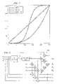
- FIG. 7 shows a set of exemplary non-linear transfer functions that can be used in determining the additional color component and a set of primary color components for producing images
- FIG. 8 diagrammatically illustrates another device for processing images
- FIG. 9 shows the (R, G, B) vs. white in full-on white reproduced images, wherein the white components are generated using a power law transfer function with different powers;
- FIG. 10 schematically illustrates an exemplary sequential color imaging system
- FIG. 11 schematically illustrates an exemplary color wheel having a white segment and a set of primary colors of red, green, and blue for use in the sequential imaging system as shown in FIG. 10 .
- the color management method transforms a set of primary color image components of an input image into another set of color image components commensurate with the imaging system used for producing the input image, wherein at least one of said another set of color image components is transformed with a non-linear transformation function. After the transformation, intensities of (or energies carried by) the primary color image components of the input image are re-distributed among the transformed set of primary color image components.
- an additional color channel e.g. a white color channel
- additional color can be determined based on the color that is associated with the potential sequential color separation artifact in the produced color image.
- color image components of the produced image have reduced or minimum amount of intensities (or energies); whereas the white color image component of the produced image has enhanced intensity (or energy)—thereby, significantly reducing the color separation artifact in the produced white-and-black image.
- the additional colors may be other colors than white.
- the intensity or energy re-distribution can be accomplished by calculating the additional color component of the image to be re-produced using a non-linear transfer function; and reducing intensities (or energies) of other primary color components accordingly.
- the calculation of the additional color component can be based on the tolerance of the human eyes to the sequential color artifact.
- the improved color management method is applicable to a variety of imaging systems including digital and analog imaging systems.
- the improved color management method is also applicable in imaging applications other than display.
- the imaging systems can be front projector and rear projection TV.
- the imaging systems can be systems employing an image engine having an array of individually addressable pixels, such as reflective and deflectable micromirrors, reflective and movable membranes (e.g. IMOD), liquid-crystal cells (LCDs), liquid-crystal-on-silicon cells (LCOS), or emissive cells (e.g. plasma cells).
- the imaging systems further may incorporate a passive display screen or an active display screen.
- the improved color management method is also applicable to imaging systems that use a spatially tessellated pattern of sub-pixels either in the form of red-green-blue triplets along with an achromatic sub-pixel, which may render an achromatic color on screen either using only the achromatic sub-pixel, or a desired combination of the other colored sub-pixels as well for enhanced reproduction of highlights and added brightness for white.
- the improved color management method may also be used solely or in combination with not just an achromatic sub-pixel or segment but also with sub-pixels or segments of other colors.
- FIG. 1 schematically illustrates a color engine.
- the input color set ⁇ C i ⁇ may comprise red, green, and blue colors, or other colors such as YCbCr, YPbPr, and YUV.
- One or more additional color components not included in the input set ⁇ C i ⁇ are generated by the color engine.
- ⁇ t is a transfer function, which can be linear or non-linear functions.
- An exemplary non-linear form of function ⁇ t is Min(X i ), which finds the minimum value of the set of variables X i .
- Another exemplary linear form of function ⁇ t can be:
- the transformed set ⁇ P k ⁇ has all colors of the input color image components ⁇ C i ⁇ ; and the additional color of the additional color image component is a linear combination of additive colors of the input color image components.
- P i can be any desired color combinations depending upon the input color set.
- the output color set can comprise colors that are selected from red, green, blue, cyan, magenta, and yellow and white.
- the “white” in the context is not limited to any specific white point in a specific standard. Instead, the “white” can be any “white point” specified in current video and monitor systems.
- the “white” in this disclosure can be a color when used as a segment of a spinning color wheel, the white segment still filters the incident light—that is, the exit (filtered) light from the white segment has a spectrum that is different from the spectrum of the incident light.
- Intensities of or energies carried by the input color image components ⁇ C i ⁇ are re-distributed among the output color image components ⁇ P k ⁇ . Specifically, the intensity of (or the energy carried by) the out additional color component is allotted from the input color image components; and intensities of the input color components are reduced. Accordingly, other output color image components having the same colors as the input color image components have less intensities and energies than the input color image components.
- the transformation of at least one additional color image component includes a non-linear transfer function.
- the white color is the linear combination of red, green, and blue colors of substantially the same amount; while the amplitude is obtained through a non-linear power law transfer function, which will be discussed more afterwards.
- the input and output of the color engine are parallel such that the input color image components can be delivered to the color engine in parallel; and the output transformed color image components can be output in parallel.
- the input and/or the output of the color engine can be serial, which is not shown in the figure.
- imaging system 100 comprises image engine 108 that is designated to produce images using image data derived from desired images.
- Image engine may comprise an array of individually addressable pixels, such as reflective and deflectable micromirrors, reflective and movable membranes (e.g. IMOD), liquid-crystal cells (LCDs), liquid-crystal-on-silicon cells (LCOS), or emissive cells (e.g. plasma cells).
- IMOD reflective and deflectable micromirrors
- LCDs liquid-crystal cells
- LCOS liquid-crystal-on-silicon cells
- emissive cells e.g. plasma cells
- the image engine also may comprise a spatially tessellated pattern of sub-pixels either in the form of red-green-blue triplets along with an achromatic sub-pixel, which may render an achromatic color on screen either using only the achromatic sub-pixel, or a desired combination of the other colored sub-pixels as well for enhanced reproduction of highlights and added brightness for white.
- the image data used by the image engine for generating the desired image is prepared by image processor 106 of system controller 104 as shown in FIG. 2 .
- the image processor retrieves (or receives) input image signals from image source 102 , which may or may not be a member of the imaging system; and processes the input image signals accordingly; and transforms the processed image signals into proper format, such as bitplane data format, that can be used by the image engine.
- the system controller is designated to control and synchronize operations of the functional members of the imaging system.
- the image processor is a device in which examples of the improved color management method can be implemented.
- the image processor comprises the color engine 110 as discussed above with reference to FIG. 1 .
- FIG. 3 schematically illustrates a structure of image processor 106 in FIG. 2 .
- image processor 106 comprises color engine 110 and data formatter that transforms the image data from one format to the proper data format that can be directly used by the image engine,
- the data formatter is capable of transforming pixel-by-pixel data (pixel data) into bitplane-by-bitplane data (bitplane data).
- the input image signals ⁇ C i ⁇ is transformed by color engine 110 into transformed image signals ⁇ P k ⁇ that is further formatted by the data formatter into bitplane data.
- FIG. 4 Another exemplary image processor is schematically illustrated in FIG. 4 .
- the image processor comprises color space converter 114 , color multiplexer 116 , color engine 110 , and data formatter 112 .
- the color space converter ( 114 ) is designated for mapping the color space of the input images into the color space of the imaging system ( 100 in FIG. 2 ).
- Color multiplexer 116 outputs color image components based on the input image and the output of the color space converter ( 114 ).
- the processed image signals are delivered to color engine 110 that processes the color image, which will be discussed in the following.
- the processed color image from color engine 110 can then be delivered to data formatter 112 that formats the image data to proper format, such as bitplane data that can be directly used by the image engine.
- data formatter 112 formats the image data to proper format, such as bitplane data that can be directly used by the image engine.
- other functional modules such as a de-gamma module can be provided, for example between the color multiplexer and data formatter.
- the color engine ( 110 ) transforms the input color image components into a new set of color image components as discussed above. This operation will be discussed in the following with particular examples wherein the input color image components have red, green, and blue colors and the output color image components comprise red, green, blue, and an additional color—white. It will be appreciated by those skilled in the art that the following discussion is for demonstration purpose, and should not be interpreted as a limitation. Other variations without departing from the spirit of the invention are also applicable.
- the input color image components can be any color combinations, the color of each preferably selected from red, green, blue, cyan, magenta, yellow, and white.
- the transformed color image components also may comprise different color combinations.
- the generated additional color is not necessarily one white color, instead, can be any other colors or any other number of different colors.
- an intermediate value W is calculated from input C i that comprises red, green, and blue by transfer function ⁇ t .
- ⁇ t is the minimum operation of the input variants
- W then is the minimum value of the input R (red), G (green), and B (blue) signals (step 118 ).
- the minimum value W is then transferred to W′ using a non-linear transfer function ⁇ (step 120 ).
- FIG. 7 presents three exemplary non-linear transfer functions that can be used in the improved color management method. Of course, other non-linear functions are also applicable, such as the following equations:
- W′ is then subtracted from the R, G, and B, values to obtain new primary color values of R′, G′, and B′ (step 122 ) as expressed in the following.
- R′ R ⁇ W′
- G′ G ⁇ W′
- B′ B ⁇ W′
- W is set to 30, which is the minimum of R, G, and B.
- the calculated W′, R′, G′, and B′ are then used to independently drive the four color channels in the display operation.
- the above method can be implemented as a software module having computer-executable instructions; and the software can be stored in a computer-readable medium.
- the above method can be implemented in an electronic circuit device that can be included in the color engine as discussed above with reference to FIG. 1 .
- An exemplary electronic circuit is shown in FIG. 6 .
- the electronic circuit can be Field-programmable-gate-arrays (FPGA) or ASIC.
- device 126 comprises multiple inputs for receiving primary color components ⁇ C i ⁇ , such as R i , G i , and B i . Though the inputs are parallel as shown in the figure, the inputs can alternatively be serial, which is not shown in the figure.
- Transformation module ⁇ t 128 is connected to the inputs and is designated to transform the input color image components into an intermediate value W.
- ⁇ t can be the minimum operation
- the intermediate vale W is then the minimum value of the input color image components.
- the output W of the ⁇ t function module is connected to the input of the non-linear filter ⁇ 130 that transfers the input signal W into a transferred new value W′.
- the new value W′ is output, for example, to other functional modules, such as de-gamma module for further processing.
- the calculated W′ is fed into multipliers and multiplied by coefficients ⁇ R , ⁇ G , and ⁇ B ; and the products are respectively delivered to subtract nodes respectively connected to the input R i , G i , and B i signals to generate outputs R o , G o , and B o .
- the output W o such as output white component, is obtained as a sum of W multiplied by coefficient ⁇ and W′ multiplied by coefficient ⁇ .
- coefficients ⁇ R , ⁇ G , and ⁇ B can be 1.0. Otherwise, the coefficients can be used to individually adjusting the primary color levels, in which instance, ⁇ R , ⁇ G , and ⁇ B may or may not be the same, but preferably between 0 and 1 inclusive.
- Coefficients ⁇ and ⁇ are predetermined and preferably dynamically adjustable coefficients, which can be 1.
- a 3-dimensional Look-Up-Table can be used along with the improved color management method.
- primary color inputs e.g. three primary colors of red, green, and blue
- This configuration with 3D LUT enables precise control of W′.
- W can be assigned to the minimum value of input primary colors, such as R, G, and B; and R′, G′, and B′ can be calculated as a result of the application of the non-linear function, which is then subtracted from the input primary color values of R, G, and B.
- ⁇ and ⁇ are variables with ⁇ being assigned to control the amount of white component contributed by the input (R, G, and B.), and the input is anyone of R, G, and B.
- the above method can be implemented as a software module having computer-executable instructions; and the software can be stored in a computer-readable medium.
- the above method can be implemented in an electronic circuit device that can be included as a member of the color engine 110 as discussed above with reference to FIG. 1 .
- the electronic circuit is schematically illustrated in FIG. 8 .
- the electronic circuit can be Field-programmable-gate-arrays (FPGA) or ASIC.
- device 132 comprises multiple inputs for receiving primary color components, such as R i , G i , and B i . Though the inputs are parallel as shown in the figure, the inputs can alternatively be serial, which is not shown in the figure.
- the ⁇ t transformation function module which can be a Min function, is connected to the inputs and is designated to obtain the minimum value of the inputs.
- the output W of the min function module is connected to the input of the non-linear filter f that transfers the input signal W into a transferred new value W′.
- the calculated W′ is fed into multipliers and multiplied by coefficients ⁇ R , ⁇ G , and ⁇ B ; and the products are respectively delivered to subtract nodes respectively connected to the input R i , G i , and B i signals to generate outputs R o , G o , and B o ,
- Coefficients ⁇ R , ⁇ G , and ⁇ B are used to control the amount of deduction from individual primary colors. These coefficients can also be assigned as the color correction factors for correcting the difference the “white color” defined by the white segment of the color
- the calculated R o , G o , and B o are delivered to multiple multipliers and respectively multiplied by coefficients of ⁇ R , ⁇ G , and ⁇ B .
- the products are input to an adder to be added with the calculated W′ multiplied by coefficient ⁇ and W multiplied by coefficient ⁇ .
- the summation is then output as the white signal W o .
- R o R i ⁇ R ⁇ W′
- G o G i ⁇ G ⁇ W′
- B o B i ⁇ B ⁇ W′
- W o ⁇ W′+ ⁇ W+[ ⁇ R ⁇ ( R i ⁇ R ⁇ W ′)+ ⁇ G ⁇ ( G i ⁇ G ⁇ W ′)+ ⁇ B ⁇ ( B i ⁇ B ⁇ W ′)]
- FIG. 9 shows the (R, G, B) vs. white in a full-on white reproduced image with the white being generated by the low-law function in equation 2 with different power ⁇ .
- the full-on white is W′ equals 255; and R′, G′, and B′ are 255.
- the power ⁇ is preferably less than 1, and more preferably less than 0.8.
- the improved color management method can be implemented in imaging systems.
- it can be implemented in sequential color imaging systems with reduced or eliminated sequential color artifacts appeared in most current sequential color imaging systems.
- FIG. 10 schematically illustrates a sequential color imaging system employing a spinning color wheel.
- imaging system 134 comprises illumination system 136 for providing illumination light, image engine 110 that modulates the incident light based on image data so as to reproduce the desired image, projection lens 146 that projects the modulated light onto screen 108 for viewing.
- the illumination system further comprises light source 138 that can be an arc lamp or other light sources capable of emitting light, such as lasers and LEDs, light integrator 140 , color wheel 142 , and condensing lens 144 .
- the image engine comprises an array of individually addressable pixels of any suitable forms.
- the pixels can be reflective and deflectable micromirrors, LCD cells, LCOS cells, and other suitable devices.
- the image data used by the display is derived from input images from image source 102 by image processor 106 of system controller 104 .
- the system controller is designated to control and synchronize operations of the functional members of the imaging system.
- Color wheel 142 comprises a set of primary colors and a white segment, as shown in FIG. 11 .
- the primary colors in this particular example comprises red, green, and blue, along with the white segment.
- Each color segment may have any suitable angles.
- the red, green, blue, and white segments may respectively have 120, 90, 90, and 60 degree angles.
- FIG. 11 shows only one of many possible examples.
- the primary colors of red, green, and blue may not in the order as shown in FIG. 11 .
- the color wheel may have other primary color combinations with the primary colors preferably selected from, red, green, blue, cyan, magenta, and yellow.
- the additional color or colors may be other colors than white.
Abstract
Description
{P k }=ƒ t({C i}), wherein k=[1,M],i=[1,N], and M>N (Eq. 1)
ƒt is a transfer function, which can be linear or non-linear functions. An exemplary non-linear form of function ƒt is Min(Xi), which finds the minimum value of the set of variables Xi. Another exemplary linear form of function ƒt can be:
wherein ηi is a set of coefficients; and xi are variants.
wherein τ and ζ are variables.
W′=ƒ(W)=ƒ[ƒt,(R,G,B)]=ƒ[Min(R,G,B)]
R′=R−W′
G′=G−W′
B′=B−W′
W′=ƒ(W)=ƒ[ƒt(R i ,G i ,B i)]=ƒ[Min(R i ,G i ,B i)]
W o =ω×W+λ×W′=ω×Min(R i ,G i ,B i)+λ׃[Min(R i ,G i ,B i)]
R o ′=R i−αR ×W′
G o ′=G i−αG ×W′
B o ′=B i−αB ×W′
Coefficients αR, αG, and αB are used to control the amount of deduction from individual primary colors. These coefficients can also be assigned as the color correction factors for correcting the difference the “white color” defined by the white segment of the color filter and the “white color” generated by the combination of other primary color segments in the color filter. When the difference is substantially zero or below a predetermined threshold, the coefficients αR, αG, and αB all can be 1.0. Otherwise, the coefficients can be used to individually adjusting the primary color levels, in which instance, αR, αG, and αB may or may not be the same, but preferably between 0 and 1 inclusive. Coefficients ω and λ are predetermined and preferably dynamically adjustable coefficients, which can be 1.
wherein τ and ζ are variables with τ being assigned to control the amount of white component contributed by the input (R, G, and B.), and the input is anyone of R, G, and B.
W′=ƒ(W)=ƒ[ƒt(R i ,G i ,B i)]=ƒ[Min(R i ,G i ,B i)]
R o ′=R i−αR ×W′
G o ′=G i−αG ×W′
B o ′=B i−αB ×W′
Coefficients αR, αG, and αB are used to control the amount of deduction from individual primary colors. These coefficients can also be assigned as the color correction factors for correcting the difference the “white color” defined by the white segment of the color filter and the “white color” generated by the combination of other color segments in the color filter.
W′=ƒ(W)=ƒ[ƒt(R i ,G i ,B i)]=ƒ[Min(R i ,G i ,B i)]
R o =R i−αR ×W′
G o =G i−αG ×W′
B o =B i−αB ×W′
W o =λ×W′+ω×W+[β R×(R i−αR ×W′)+βG×(G i−αG ×W′)+βB×(B i−αB ×W′)]
Claims (34)
Priority Applications (3)
| Application Number | Priority Date | Filing Date | Title |
|---|---|---|---|
| US11/616,170 US7477778B2 (en) | 2006-12-26 | 2006-12-26 | Sequential color reproduction method |
| PCT/US2007/088018 WO2008082965A2 (en) | 2006-12-26 | 2007-12-19 | Sequential color reproduction method and apparatus |
| TW096150407A TWI364713B (en) | 2006-12-26 | 2007-12-26 | Sequential color reproduction method and apparatus |
Applications Claiming Priority (1)
| Application Number | Priority Date | Filing Date | Title |
|---|---|---|---|
| US11/616,170 US7477778B2 (en) | 2006-12-26 | 2006-12-26 | Sequential color reproduction method |
Publications (2)
| Publication Number | Publication Date |
|---|---|
| US20080152219A1 US20080152219A1 (en) | 2008-06-26 |
| US7477778B2 true US7477778B2 (en) | 2009-01-13 |
Family
ID=39542893
Family Applications (1)
| Application Number | Title | Priority Date | Filing Date |
|---|---|---|---|
| US11/616,170 Active 2027-02-08 US7477778B2 (en) | 2006-12-26 | 2006-12-26 | Sequential color reproduction method |
Country Status (3)
| Country | Link |
|---|---|
| US (1) | US7477778B2 (en) |
| TW (1) | TWI364713B (en) |
| WO (1) | WO2008082965A2 (en) |
Cited By (2)
| Publication number | Priority date | Publication date | Assignee | Title |
|---|---|---|---|---|
| US20090009664A1 (en) * | 2003-10-30 | 2009-01-08 | Masahiro Kawashima | Color image processing apparatus, color image processing method, program and recording medium |
| US20150016538A1 (en) * | 2013-07-10 | 2015-01-15 | Sony Corporation | Signal processing apparatus, signal processing method, program, and signal transmission system |
Families Citing this family (8)
| Publication number | Priority date | Publication date | Assignee | Title |
|---|---|---|---|---|
| KR101479993B1 (en) | 2008-10-14 | 2015-01-08 | 삼성디스플레이 주식회사 | Four color display device and method of converting image signal therefor |
| US8952980B2 (en) * | 2010-08-09 | 2015-02-10 | Gsi Group, Inc. | Electronic color and luminance modification |
| JP2014515838A (en) * | 2011-04-21 | 2014-07-03 | ザ ユニバーシティ オブ ワシントン スルー イッツ センター フォー コマーシャライゼーション | Video display to suppress myopia |
| CN103680413B (en) * | 2013-12-31 | 2015-07-01 | 京东方科技集团股份有限公司 | Image processing device and image processing method |
| US10192477B2 (en) * | 2015-01-08 | 2019-01-29 | Lighthouse Technologies Limited | Pixel combination of full color LED and white LED for use in LED video displays and signages |
| CN105425407B (en) * | 2015-12-31 | 2019-03-19 | 上海天马微电子有限公司 | A kind of 3D display device and electronic equipment |
| US20190057673A1 (en) | 2016-01-18 | 2019-02-21 | Waveshift Llc | Method and apparatus for reducing myopiagenic effect of electronic displays |
| GB2613194A (en) * | 2021-11-29 | 2023-05-31 | Samsung Electronics Co Ltd | Image processing |
Citations (7)
| Publication number | Priority date | Publication date | Assignee | Title |
|---|---|---|---|---|
| US5929843A (en) * | 1991-11-07 | 1999-07-27 | Canon Kabushiki Kaisha | Image processing apparatus which extracts white component data |
| US6335734B1 (en) * | 1998-11-26 | 2002-01-01 | Fujitsu Limited | Color converting method |
| US6529291B1 (en) * | 1999-09-22 | 2003-03-04 | Xerox Corporation | Fuzzy black color conversion using weighted outputs and matched tables |
| US6536904B2 (en) * | 2000-12-30 | 2003-03-25 | Texas Instruments Incorporated | Reduced color separation white enhancement for sequential color displays |
| US6552495B1 (en) * | 2001-12-19 | 2003-04-22 | Koninklijke Philips Electronics N.V. | Adaptive control system and method with spatial uniform color metric for RGB LED based white light illumination |
| US6876764B2 (en) * | 1999-10-08 | 2005-04-05 | Samsung Electronics Co., Ltd. | Method and apparatus for generating white component and controlling the brightness in display devices |
| US20060214945A1 (en) | 2005-03-23 | 2006-09-28 | Seiko Epson Corporation | Display device and display method |
-
2006
- 2006-12-26 US US11/616,170 patent/US7477778B2/en active Active
-
2007
- 2007-12-19 WO PCT/US2007/088018 patent/WO2008082965A2/en active Application Filing
- 2007-12-26 TW TW096150407A patent/TWI364713B/en active
Patent Citations (7)
| Publication number | Priority date | Publication date | Assignee | Title |
|---|---|---|---|---|
| US5929843A (en) * | 1991-11-07 | 1999-07-27 | Canon Kabushiki Kaisha | Image processing apparatus which extracts white component data |
| US6335734B1 (en) * | 1998-11-26 | 2002-01-01 | Fujitsu Limited | Color converting method |
| US6529291B1 (en) * | 1999-09-22 | 2003-03-04 | Xerox Corporation | Fuzzy black color conversion using weighted outputs and matched tables |
| US6876764B2 (en) * | 1999-10-08 | 2005-04-05 | Samsung Electronics Co., Ltd. | Method and apparatus for generating white component and controlling the brightness in display devices |
| US6536904B2 (en) * | 2000-12-30 | 2003-03-25 | Texas Instruments Incorporated | Reduced color separation white enhancement for sequential color displays |
| US6552495B1 (en) * | 2001-12-19 | 2003-04-22 | Koninklijke Philips Electronics N.V. | Adaptive control system and method with spatial uniform color metric for RGB LED based white light illumination |
| US20060214945A1 (en) | 2005-03-23 | 2006-09-28 | Seiko Epson Corporation | Display device and display method |
Cited By (4)
| Publication number | Priority date | Publication date | Assignee | Title |
|---|---|---|---|---|
| US20090009664A1 (en) * | 2003-10-30 | 2009-01-08 | Masahiro Kawashima | Color image processing apparatus, color image processing method, program and recording medium |
| US7643094B2 (en) * | 2003-10-30 | 2010-01-05 | Panasonic Corporation | Color image processing apparatus, color image processing method, program and recording medium |
| US20150016538A1 (en) * | 2013-07-10 | 2015-01-15 | Sony Corporation | Signal processing apparatus, signal processing method, program, and signal transmission system |
| US9479789B2 (en) * | 2013-07-10 | 2016-10-25 | Sony Corporation | Signal processing apparatus, signal processing method, program, and signal transmission system |
Also Published As
| Publication number | Publication date |
|---|---|
| TWI364713B (en) | 2012-05-21 |
| TW200842730A (en) | 2008-11-01 |
| US20080152219A1 (en) | 2008-06-26 |
| WO2008082965A3 (en) | 2008-09-04 |
| WO2008082965A2 (en) | 2008-07-10 |
Similar Documents
| Publication | Publication Date | Title |
|---|---|---|
| US7477778B2 (en) | Sequential color reproduction method | |
| KR101207318B1 (en) | Method of driving displays comprising a conversion from the rgb colour space to the rgbw colour space | |
| US6453067B1 (en) | Brightness gain using white segment with hue and gain correction | |
| US20080158259A1 (en) | Image warping and lateral color correction | |
| US6536904B2 (en) | Reduced color separation white enhancement for sequential color displays | |
| KR100565810B1 (en) | Color signal processing apparatus and method of using the same | |
| EP2238504B1 (en) | Display with two binary spatial light modulators | |
| EP2460358B1 (en) | Display method with expanded color gamut | |
| EP1427221A2 (en) | Dynamic range enhancement of image display apparatus | |
| CN104509105A (en) | Display system providing observer metameric failure reduction | |
| JP2009500654A (en) | Method and apparatus for converting signals for driving a display, and display using the method and apparatus | |
| US9390660B2 (en) | Image control for displays | |
| CN104509106A (en) | Observer metameric failure compensation method | |
| CN104509104A (en) | Observer metameric failure reduction method | |
| JPWO2003001499A1 (en) | Image display system, projector, image processing method, and information storage medium | |
| EP2161918B1 (en) | Image processor, image display device, image processing method, and image display method | |
| US20120218283A1 (en) | Method for Obtaining Brighter Images from an LED Projector | |
| KR20150081174A (en) | Liquid crystal display apparatus and the drivinig method of the same | |
| JP5487597B2 (en) | Image processing apparatus, image display apparatus, and image processing method | |
| JP2006153914A (en) | Liquid crystal projector | |
| JP5785996B2 (en) | Method and system for improving an image provided by a spatial light modulation (SLM) display system | |
| US20190012950A1 (en) | Projector for projecting a multi-colored image | |
| US20110149167A1 (en) | Full Visible Gamut Color Video Display | |
| JP3969414B2 (en) | Video signal processing device | |
| JP2010157900A (en) | Signal processing device and projection video display device |
Legal Events
| Date | Code | Title | Description |
|---|---|---|---|
| AS | Assignment |
Owner name: TEXAS INSTRUMENTS INCORPORATED, TEXAS Free format text: ASSIGNMENT OF ASSIGNORS INTEREST;ASSIGNORS:RAMANATH, RAJEEV;DOHERTY, DONALD B;PETTIT, GREGORY S;REEL/FRAME:019960/0588 Effective date: 20070102 |
|
| STCF | Information on status: patent grant |
Free format text: PATENTED CASE |
|
| FPAY | Fee payment |
Year of fee payment: 4 |
|
| FPAY | Fee payment |
Year of fee payment: 8 |
|
| MAFP | Maintenance fee payment |
Free format text: PAYMENT OF MAINTENANCE FEE, 12TH YEAR, LARGE ENTITY (ORIGINAL EVENT CODE: M1553); ENTITY STATUS OF PATENT OWNER: LARGE ENTITY Year of fee payment: 12 |