JP2015018954A - Method for manufacturing nanocomposite thermoelectric conversion material - Google Patents
Method for manufacturing nanocomposite thermoelectric conversion material Download PDFInfo
- Publication number
- JP2015018954A JP2015018954A JP2013145503A JP2013145503A JP2015018954A JP 2015018954 A JP2015018954 A JP 2015018954A JP 2013145503 A JP2013145503 A JP 2013145503A JP 2013145503 A JP2013145503 A JP 2013145503A JP 2015018954 A JP2015018954 A JP 2015018954A
- Authority
- JP
- Japan
- Prior art keywords
- nanoparticles
- group element
- thermoelectric conversion
- conversion material
- phonon scattering
- Prior art date
- Legal status (The legal status is an assumption and is not a legal conclusion. Google has not performed a legal analysis and makes no representation as to the accuracy of the status listed.)
- Granted
Links
- 238000006243 chemical reaction Methods 0.000 title claims abstract description 99
- 239000000463 material Substances 0.000 title claims abstract description 80
- 239000002114 nanocomposite Substances 0.000 title claims abstract description 30
- 238000004519 manufacturing process Methods 0.000 title claims abstract description 15
- 238000000034 method Methods 0.000 title claims abstract description 6
- 239000002105 nanoparticle Substances 0.000 claims abstract description 148
- 239000002245 particle Substances 0.000 claims abstract description 94
- 239000002243 precursor Substances 0.000 claims abstract description 35
- 150000003839 salts Chemical class 0.000 claims abstract description 33
- 239000000203 mixture Substances 0.000 claims abstract description 27
- 239000002131 composite material Substances 0.000 claims abstract description 24
- 239000011159 matrix material Substances 0.000 claims abstract description 22
- 238000001556 precipitation Methods 0.000 claims abstract description 16
- 238000010335 hydrothermal treatment Methods 0.000 claims abstract description 13
- 239000000956 alloy Substances 0.000 claims abstract description 12
- 229910045601 alloy Inorganic materials 0.000 claims abstract description 12
- 238000006116 polymerization reaction Methods 0.000 claims abstract description 9
- 238000005245 sintering Methods 0.000 claims abstract description 9
- 239000003638 chemical reducing agent Substances 0.000 claims description 23
- 239000002244 precipitate Substances 0.000 claims description 6
- -1 respectively Substances 0.000 claims description 3
- 229910004298 SiO 2 Inorganic materials 0.000 description 30
- KFZMGEQAYNKOFK-UHFFFAOYSA-N Isopropanol Chemical compound CC(C)O KFZMGEQAYNKOFK-UHFFFAOYSA-N 0.000 description 21
- LFQSCWFLJHTTHZ-UHFFFAOYSA-N Ethanol Chemical compound CCO LFQSCWFLJHTTHZ-UHFFFAOYSA-N 0.000 description 17
- 239000002904 solvent Substances 0.000 description 14
- 230000000694 effects Effects 0.000 description 13
- 230000000052 comparative effect Effects 0.000 description 12
- HHFAWKCIHAUFRX-UHFFFAOYSA-N ethoxide Chemical compound CC[O-] HHFAWKCIHAUFRX-UHFFFAOYSA-N 0.000 description 11
- BOTDANWDWHJENH-UHFFFAOYSA-N Tetraethyl orthosilicate Chemical compound CCO[Si](OCC)(OCC)OCC BOTDANWDWHJENH-UHFFFAOYSA-N 0.000 description 9
- 239000000843 powder Substances 0.000 description 9
- 239000002994 raw material Substances 0.000 description 9
- 229910015902 Bi 2 O 3 Inorganic materials 0.000 description 8
- 229910010413 TiO 2 Inorganic materials 0.000 description 8
- 230000007423 decrease Effects 0.000 description 8
- 229960004592 isopropanol Drugs 0.000 description 7
- 230000015572 biosynthetic process Effects 0.000 description 6
- 150000004703 alkoxides Chemical class 0.000 description 5
- XLYOFNOQVPJJNP-UHFFFAOYSA-N water Substances O XLYOFNOQVPJJNP-UHFFFAOYSA-N 0.000 description 5
- IJGRMHOSHXDMSA-UHFFFAOYSA-N Atomic nitrogen Chemical compound N#N IJGRMHOSHXDMSA-UHFFFAOYSA-N 0.000 description 4
- 239000012298 atmosphere Substances 0.000 description 4
- 230000008021 deposition Effects 0.000 description 4
- 229910001873 dinitrogen Inorganic materials 0.000 description 4
- OKKJLVBELUTLKV-UHFFFAOYSA-N Methanol Chemical compound OC OKKJLVBELUTLKV-UHFFFAOYSA-N 0.000 description 3
- 239000004115 Sodium Silicate Substances 0.000 description 3
- 239000000470 constituent Substances 0.000 description 3
- BDERNNFJNOPAEC-UHFFFAOYSA-N propan-1-ol Chemical compound CCCO BDERNNFJNOPAEC-UHFFFAOYSA-N 0.000 description 3
- 239000002002 slurry Substances 0.000 description 3
- NTHWMYGWWRZVTN-UHFFFAOYSA-N sodium silicate Chemical compound [Na+].[Na+].[O-][Si]([O-])=O NTHWMYGWWRZVTN-UHFFFAOYSA-N 0.000 description 3
- 229910052911 sodium silicate Inorganic materials 0.000 description 3
- CIWBSHSKHKDKBQ-JLAZNSOCSA-N Ascorbic acid Chemical compound OC[C@H](O)[C@H]1OC(=O)C(O)=C1O CIWBSHSKHKDKBQ-JLAZNSOCSA-N 0.000 description 2
- 239000006185 dispersion Substances 0.000 description 2
- 238000003756 stirring Methods 0.000 description 2
- 230000005641 tunneling Effects 0.000 description 2
- PEDCQBHIVMGVHV-UHFFFAOYSA-N Glycerine Chemical compound OCC(O)CO PEDCQBHIVMGVHV-UHFFFAOYSA-N 0.000 description 1
- 229960005070 ascorbic acid Drugs 0.000 description 1
- 235000010323 ascorbic acid Nutrition 0.000 description 1
- 239000011668 ascorbic acid Substances 0.000 description 1
- 239000000969 carrier Substances 0.000 description 1
- 239000013065 commercial product Substances 0.000 description 1
- 230000003247 decreasing effect Effects 0.000 description 1
- 238000009792 diffusion process Methods 0.000 description 1
- 238000001035 drying Methods 0.000 description 1
- 238000001027 hydrothermal synthesis Methods 0.000 description 1
- 239000012535 impurity Substances 0.000 description 1
- 238000005259 measurement Methods 0.000 description 1
- 238000002360 preparation method Methods 0.000 description 1
- 239000000376 reactant Substances 0.000 description 1
- 238000003786 synthesis reaction Methods 0.000 description 1
- 238000002604 ultrasonography Methods 0.000 description 1
- 238000005406 washing Methods 0.000 description 1
Images


Classifications
-
- B—PERFORMING OPERATIONS; TRANSPORTING
- B22—CASTING; POWDER METALLURGY
- B22F—WORKING METALLIC POWDER; MANUFACTURE OF ARTICLES FROM METALLIC POWDER; MAKING METALLIC POWDER; APPARATUS OR DEVICES SPECIALLY ADAPTED FOR METALLIC POWDER
- B22F9/00—Making metallic powder or suspensions thereof
- B22F9/16—Making metallic powder or suspensions thereof using chemical processes
- B22F9/18—Making metallic powder or suspensions thereof using chemical processes with reduction of metal compounds
- B22F9/24—Making metallic powder or suspensions thereof using chemical processes with reduction of metal compounds starting from liquid metal compounds, e.g. solutions
-
- B—PERFORMING OPERATIONS; TRANSPORTING
- B22—CASTING; POWDER METALLURGY
- B22F—WORKING METALLIC POWDER; MANUFACTURE OF ARTICLES FROM METALLIC POWDER; MAKING METALLIC POWDER; APPARATUS OR DEVICES SPECIALLY ADAPTED FOR METALLIC POWDER
- B22F3/00—Manufacture of workpieces or articles from metallic powder characterised by the manner of compacting or sintering; Apparatus specially adapted therefor ; Presses and furnaces
- B22F3/10—Sintering only
- B22F3/105—Sintering only by using electric current other than for infrared radiant energy, laser radiation or plasma ; by ultrasonic bonding
-
- C—CHEMISTRY; METALLURGY
- C22—METALLURGY; FERROUS OR NON-FERROUS ALLOYS; TREATMENT OF ALLOYS OR NON-FERROUS METALS
- C22C—ALLOYS
- C22C32/00—Non-ferrous alloys containing at least 5% by weight but less than 50% by weight of oxides, carbides, borides, nitrides, silicides or other metal compounds, e.g. oxynitrides, sulfides, whether added as such or formed in situ
- C22C32/001—Non-ferrous alloys containing at least 5% by weight but less than 50% by weight of oxides, carbides, borides, nitrides, silicides or other metal compounds, e.g. oxynitrides, sulfides, whether added as such or formed in situ with only oxides
- C22C32/0015—Non-ferrous alloys containing at least 5% by weight but less than 50% by weight of oxides, carbides, borides, nitrides, silicides or other metal compounds, e.g. oxynitrides, sulfides, whether added as such or formed in situ with only oxides with only single oxides as main non-metallic constituents
-
- H—ELECTRICITY
- H10—SEMICONDUCTOR DEVICES; ELECTRIC SOLID-STATE DEVICES NOT OTHERWISE PROVIDED FOR
- H10N—ELECTRIC SOLID-STATE DEVICES NOT OTHERWISE PROVIDED FOR
- H10N10/00—Thermoelectric devices comprising a junction of dissimilar materials, i.e. devices exhibiting Seebeck or Peltier effects
- H10N10/01—Manufacture or treatment
-
- H—ELECTRICITY
- H10—SEMICONDUCTOR DEVICES; ELECTRIC SOLID-STATE DEVICES NOT OTHERWISE PROVIDED FOR
- H10N—ELECTRIC SOLID-STATE DEVICES NOT OTHERWISE PROVIDED FOR
- H10N10/00—Thermoelectric devices comprising a junction of dissimilar materials, i.e. devices exhibiting Seebeck or Peltier effects
- H10N10/80—Constructional details
- H10N10/85—Thermoelectric active materials
- H10N10/851—Thermoelectric active materials comprising inorganic compositions
- H10N10/853—Thermoelectric active materials comprising inorganic compositions comprising arsenic, antimony or bismuth
-
- H—ELECTRICITY
- H10—SEMICONDUCTOR DEVICES; ELECTRIC SOLID-STATE DEVICES NOT OTHERWISE PROVIDED FOR
- H10N—ELECTRIC SOLID-STATE DEVICES NOT OTHERWISE PROVIDED FOR
- H10N10/00—Thermoelectric devices comprising a junction of dissimilar materials, i.e. devices exhibiting Seebeck or Peltier effects
- H10N10/80—Constructional details
- H10N10/85—Thermoelectric active materials
- H10N10/857—Thermoelectric active materials comprising compositions changing continuously or discontinuously inside the material
-
- B—PERFORMING OPERATIONS; TRANSPORTING
- B22—CASTING; POWDER METALLURGY
- B22F—WORKING METALLIC POWDER; MANUFACTURE OF ARTICLES FROM METALLIC POWDER; MAKING METALLIC POWDER; APPARATUS OR DEVICES SPECIALLY ADAPTED FOR METALLIC POWDER
- B22F9/00—Making metallic powder or suspensions thereof
- B22F9/16—Making metallic powder or suspensions thereof using chemical processes
- B22F9/18—Making metallic powder or suspensions thereof using chemical processes with reduction of metal compounds
- B22F9/24—Making metallic powder or suspensions thereof using chemical processes with reduction of metal compounds starting from liquid metal compounds, e.g. solutions
- B22F2009/245—Reduction reaction in an Ionic Liquid [IL]
-
- B—PERFORMING OPERATIONS; TRANSPORTING
- B22—CASTING; POWDER METALLURGY
- B22F—WORKING METALLIC POWDER; MANUFACTURE OF ARTICLES FROM METALLIC POWDER; MAKING METALLIC POWDER; APPARATUS OR DEVICES SPECIALLY ADAPTED FOR METALLIC POWDER
- B22F2301/00—Metallic composition of the powder or its coating
- B22F2301/05—Light metals
- B22F2301/052—Aluminium
-
- B—PERFORMING OPERATIONS; TRANSPORTING
- B22—CASTING; POWDER METALLURGY
- B22F—WORKING METALLIC POWDER; MANUFACTURE OF ARTICLES FROM METALLIC POWDER; MAKING METALLIC POWDER; APPARATUS OR DEVICES SPECIALLY ADAPTED FOR METALLIC POWDER
- B22F2301/00—Metallic composition of the powder or its coating
- B22F2301/20—Refractory metals
- B22F2301/205—Titanium, zirconium or hafnium
-
- B—PERFORMING OPERATIONS; TRANSPORTING
- B22—CASTING; POWDER METALLURGY
- B22F—WORKING METALLIC POWDER; MANUFACTURE OF ARTICLES FROM METALLIC POWDER; MAKING METALLIC POWDER; APPARATUS OR DEVICES SPECIALLY ADAPTED FOR METALLIC POWDER
- B22F2301/00—Metallic composition of the powder or its coating
- B22F2301/30—Low melting point metals, i.e. Zn, Pb, Sn, Cd, In, Ga
-
- B—PERFORMING OPERATIONS; TRANSPORTING
- B22—CASTING; POWDER METALLURGY
- B22F—WORKING METALLIC POWDER; MANUFACTURE OF ARTICLES FROM METALLIC POWDER; MAKING METALLIC POWDER; APPARATUS OR DEVICES SPECIALLY ADAPTED FOR METALLIC POWDER
- B22F2302/00—Metal Compound, non-Metallic compound or non-metal composition of the powder or its coating
- B22F2302/25—Oxide
- B22F2302/253—Aluminum oxide (Al2O3)
-
- B—PERFORMING OPERATIONS; TRANSPORTING
- B22—CASTING; POWDER METALLURGY
- B22F—WORKING METALLIC POWDER; MANUFACTURE OF ARTICLES FROM METALLIC POWDER; MAKING METALLIC POWDER; APPARATUS OR DEVICES SPECIALLY ADAPTED FOR METALLIC POWDER
- B22F2302/00—Metal Compound, non-Metallic compound or non-metal composition of the powder or its coating
- B22F2302/25—Oxide
- B22F2302/256—Silicium oxide (SiO2)
-
- B—PERFORMING OPERATIONS; TRANSPORTING
- B22—CASTING; POWDER METALLURGY
- B22F—WORKING METALLIC POWDER; MANUFACTURE OF ARTICLES FROM METALLIC POWDER; MAKING METALLIC POWDER; APPARATUS OR DEVICES SPECIALLY ADAPTED FOR METALLIC POWDER
- B22F2302/00—Metal Compound, non-Metallic compound or non-metal composition of the powder or its coating
- B22F2302/45—Others, including non-metals
-
- B—PERFORMING OPERATIONS; TRANSPORTING
- B22—CASTING; POWDER METALLURGY
- B22F—WORKING METALLIC POWDER; MANUFACTURE OF ARTICLES FROM METALLIC POWDER; MAKING METALLIC POWDER; APPARATUS OR DEVICES SPECIALLY ADAPTED FOR METALLIC POWDER
- B22F2304/00—Physical aspects of the powder
- B22F2304/05—Submicron size particles
-
- B—PERFORMING OPERATIONS; TRANSPORTING
- B22—CASTING; POWDER METALLURGY
- B22F—WORKING METALLIC POWDER; MANUFACTURE OF ARTICLES FROM METALLIC POWDER; MAKING METALLIC POWDER; APPARATUS OR DEVICES SPECIALLY ADAPTED FOR METALLIC POWDER
- B22F2998/00—Supplementary information concerning processes or compositions relating to powder metallurgy
- B22F2998/10—Processes characterised by the sequence of their steps
-
- B—PERFORMING OPERATIONS; TRANSPORTING
- B82—NANOTECHNOLOGY
- B82Y—SPECIFIC USES OR APPLICATIONS OF NANOSTRUCTURES; MEASUREMENT OR ANALYSIS OF NANOSTRUCTURES; MANUFACTURE OR TREATMENT OF NANOSTRUCTURES
- B82Y30/00—Nanotechnology for materials or surface science, e.g. nanocomposites
-
- B—PERFORMING OPERATIONS; TRANSPORTING
- B82—NANOTECHNOLOGY
- B82Y—SPECIFIC USES OR APPLICATIONS OF NANOSTRUCTURES; MEASUREMENT OR ANALYSIS OF NANOSTRUCTURES; MANUFACTURE OR TREATMENT OF NANOSTRUCTURES
- B82Y40/00—Manufacture or treatment of nanostructures
Abstract
Description
本発明は、特定の形状を有するフォノン散乱粒子が熱電変換材料マトリクス中に分散したナノコンポジット熱電変換材料の製造方法に関する。 The present invention relates to a method for producing a nanocomposite thermoelectric conversion material in which phonon scattering particles having a specific shape are dispersed in a thermoelectric conversion material matrix.
ナノコンポジット熱電変換材料は、熱電変換材料をマトリクスとし、このマトリクス中にナノサイズのフォノン散乱粒子をナノオーダーの間隔で分散させたナノコンポジット構造を有する熱電変換材料である。 The nanocomposite thermoelectric conversion material is a thermoelectric conversion material having a nanocomposite structure in which a thermoelectric conversion material is used as a matrix and nano-sized phonon scattering particles are dispersed in the matrix at nano-order intervals.
熱電変換材料の変換効率は下記の無次元性能指数ZTによって表される。また、α2×σ=PFは、出力因子あるいは電気特性と呼ばれる。
ZT=α2×σ×T/κ………変換効率(無次元性能指数)
α2×σ=PF…………………出力因子(電気特性)
α:ゼーベック係数
σ:電気伝導率
κ:熱伝導率
T:絶対温度
The conversion efficiency of the thermoelectric conversion material is represented by the following dimensionless figure of merit ZT. Α 2 × σ = PF is called an output factor or electrical characteristics.
ZT = α 2 × σ × T / κ ... Conversion efficiency (dimensionless figure of merit)
α 2 × σ = PF ………………… Output factor (electrical characteristics)
α: Seebeck coefficient σ: Electrical conductivity κ: Thermal conductivity T: Absolute temperature
最上式に示したように変換効率は熱伝導率κの逆数に比例するため、熱伝導率が小さいほど変換効率は高まる。ナノコンポジット熱電変換材料は、ナノサイズのフォノン散乱粒子をナノオーダーの間隔で配置してフォノン散乱を増強し、熱伝導率κのうちフォノン伝導分を低下させて熱伝導率κを低下させる。 Since the conversion efficiency is proportional to the reciprocal of the thermal conductivity κ as shown in the uppermost equation, the conversion efficiency increases as the thermal conductivity decreases. The nanocomposite thermoelectric conversion material enhances phonon scattering by arranging nano-sized phonon scattering particles at nano-order intervals, and lowers the phonon conductivity of the thermal conductivity κ to lower the thermal conductivity κ.
より高い熱電変換性能を達成するには、フォノン散乱粒子によるフォノン散乱効果を高める必要がある。例えば、特許文献1には、熱電変換材料マトリクスとフォノン散乱粒子との界面が0.1nm以上の界面粗さを付与することで、フォノン散乱効果を高めている。これにより、それ以前に比べると熱伝導率が低下し熱電変換性能が向上する。
In order to achieve higher thermoelectric conversion performance, it is necessary to enhance the phonon scattering effect by the phonon scattering particles. For example, in
しかし、フォノン散乱粒子と熱電変換材料マトリクスとの界面の粗さによる効果には限界があった。すなわち界面の粗さに留まらず、フォノン散乱粒子の形状全体をフォノン散乱に有利な形状にすれば、更に熱伝導率が低下して熱電変換性能の向上が期待されていた。 However, the effect due to the roughness of the interface between the phonon scattering particles and the thermoelectric conversion material matrix is limited. That is, if the entire shape of the phonon scattering particles is not limited to the roughness of the interface, and the shape is advantageous for phonon scattering, the thermal conductivity is further lowered and the thermoelectric conversion performance is expected to be improved.
本発明は、特定の形状のフォノン散乱粒子を分散させて熱伝導率を低減し熱電変換性能を高めたナノコンポジット熱電変換材料を製造する方法を提供することを目的とする。 An object of the present invention is to provide a method for producing a nanocomposite thermoelectric conversion material in which phonon scattering particles having a specific shape are dispersed to reduce thermal conductivity and to improve thermoelectric conversion performance.
上記の目的を達成するために、本発明の製造方法は、熱電変換材料のマトリクス中にフォノン散乱粒子として酸化物が分散したナノコンポジット熱電変換材料の製造方法であって、
溶液中で、熱電変換材料を構成する元素を塩の還元により、フォノン散乱粒子を構成する酸化物を前駆体の重合により、それぞれナノ粒子として析出および成長させ、これらナノ粒子の混合物を回収する第1段階、および
上記混合物を水熱処理により合金化して複合ナノ粒子とした後に焼結する第2段階を含み、
上記第1段階において、熱電変換材料を構成する第1群元素のナノ粒子の析出または成長を、フォノン散乱粒子を構成する第2群元素酸化物のナノ粒子の析出または成長よりも先行させることを特徴とする。
In order to achieve the above object, the production method of the present invention is a method for producing a nanocomposite thermoelectric conversion material in which an oxide is dispersed as phonon scattering particles in a matrix of a thermoelectric conversion material,
In the solution, the elements constituting the thermoelectric conversion material are precipitated and grown as nanoparticles by reduction of the salt and the oxides constituting the phonon scattering particles by polymerization of the precursor, respectively, and a mixture of these nanoparticles is recovered. And a second step of sintering the mixture by hydrothermal treatment to form composite nanoparticles,
In the first step, the precipitation or growth of the nanoparticles of the first group element constituting the thermoelectric conversion material is preceded by the precipitation or growth of the nanoparticles of the second group element oxide constituting the phonon scattering particles. Features.
本発明によれば、熱電変換材料を構成する第1群元素のナノ粒子の析出または成長を、フォノン散乱粒子を構成する第2群元素酸化物のナノ粒子の析出または成長に対して先行させることにより、先行して析出・成長し凝集した熱電変換材料ナノ粒子間の間隙または谷間を充填する状態でフォノン散乱ナノ粒子が析出・成長するので、フォノン散乱ナノ粒子の外形は2つ以上の円弧から成る多重円弧形となり、従来得られた概略球形に比べて下記(1),(2),(3)の効果が得られる。 According to the present invention, the precipitation or growth of the nanoparticles of the first group element constituting the thermoelectric conversion material precedes the precipitation or growth of the nanoparticles of the second group element oxide constituting the phonon scattering particles. The phonon scattering nanoparticles are deposited and grown in a state where the gaps or valleys between the thermoelectric conversion material nanoparticles that have been deposited, grown and aggregated in advance are filled, so that the outer shape of the phonon scattering nanoparticles can be obtained from two or more arcs. Thus, the following effects (1), (2), and (3) can be obtained as compared with the generally obtained spherical shape.
(1)同量の球形フォノン散乱粒子に比べて、フォノン散乱界面積が著しく増加し、熱伝導率が大幅に低減できる。
(2)従来の球形フォノン散乱粒子に比べて、少ない量のフォノン散乱粒子で等しい熱伝導率低減効果を達成できるので、電気絶縁性のフォノン散乱粒子を用いた場合に導電性の低下を軽減できる。
(3)伝導キャリアの入射方向によっては、キャリアのトンネル効果が起き、電気伝導率の低下を更に低減できる。
上記(1)(2)(3)の効果により、熱電変換効率ZTが大幅に向上する。
(1) Compared with the same amount of spherical phonon scattering particles, the phonon scattering interface area is remarkably increased, and the thermal conductivity can be greatly reduced.
(2) Compared to conventional spherical phonon scattering particles, the same thermal conductivity reduction effect can be achieved with a small amount of phonon scattering particles, so that the decrease in conductivity can be reduced when electrically insulating phonon scattering particles are used. .
(3) Depending on the incident direction of the conductive carrier, a tunneling effect of the carrier occurs, and the decrease in electrical conductivity can be further reduced.
Due to the effects (1), (2), and (3), the thermoelectric conversion efficiency ZT is greatly improved.
本発明は、熱電変換材料のマトリクス中にフォノン散乱粒子として酸化物が分散したナノコンポジット熱電変換材料の製造方法であって、
溶液中で、熱電変換材料を構成する元素を塩の還元により、フォノン散乱粒子を構成する酸化物を前駆体の重合により、それぞれナノ粒子として析出および成長させ、これらナノ粒子の混合物を回収する第1段階、および
上記混合物を水熱処理により合金化して複合ナノ粒子とした後に焼結する第2段階を含み、
上記第1段階において、熱電変換材料を構成する第1群元素のナノ粒子の析出または成長を、フォノン散乱粒子を構成する第2群元素酸化物のナノ粒子の析出または成長よりも先行させることを特徴とする。
The present invention is a method for producing a nanocomposite thermoelectric conversion material in which an oxide is dispersed as phonon scattering particles in a matrix of a thermoelectric conversion material,
In the solution, the elements constituting the thermoelectric conversion material are precipitated and grown as nanoparticles by reduction of the salt and the oxides constituting the phonon scattering particles by polymerization of the precursor, respectively, and a mixture of these nanoparticles is recovered. And a second step of sintering the mixture by hydrothermal treatment to form composite nanoparticles,
In the first step, the precipitation or growth of the nanoparticles of the first group element constituting the thermoelectric conversion material is preceded by the precipitation or growth of the nanoparticles of the second group element oxide constituting the phonon scattering particles. Features.
本発明において、上記第1段階において、熱電変換材料構成元素のナノ粒子の析出または成長を、フォノン散乱粒子構成酸化物のナノ粒子の析出または成長よりも先行させる方法は、下記<A><B><C>のいずれかの形態による。 In the present invention, in the first step, precipitation or growth of the thermoelectric conversion material constituting element nanoparticles precedes precipitation or growth of the phonon scattering particle constituting oxide nanoparticles by the following <A> <B > According to any form of <C>.
形態<A>
下記の工程(1)(2)を順次行う:
(1)下記条件《1》を満たすように、熱電変換材料を構成する第1群元素の塩と、
フォノン散乱粒子を構成する第2群元素酸化物の前駆体との溶液を形成する。
《1》上記溶液中において、同一の還元剤の存在下で、塩が還元されて第1群元
素のナノ粒子が析出する速度が、前駆体が重合して第2群元素酸化物のナノ粒子
が析出する速度より大きくなるように、塩および前駆体を選択する。
(2)上記溶液に還元剤を混合して塩から第1群元素のナノ粒子を析出させるのと同
時に、前駆体の重合により第2群元素酸化物のナノ粒子を析出させ、これらナノ粒子
の混合物を回収する。
Form <A>
The following steps (1) and (2) are sequentially performed:
(1) a salt of the first group element constituting the thermoelectric conversion material so as to satisfy the following condition << 1 >>
A solution is formed with a precursor of the second group element oxide constituting the phonon scattering particles.
<< 1 >> In the above solution, in the presence of the same reducing agent, the rate at which the salt is reduced and the nanoparticles of the first group element precipitate out is determined by the polymerization of the precursor and the second group element oxide nanoparticle. The salt and precursor are selected to be greater than the rate at which the particles precipitate.
(2) At the same time that the reducing agent is mixed in the above solution to precipitate the first group element nanoparticles from the salt, the second group element oxide nanoparticles are precipitated by polymerization of the precursor, and these nanoparticles The mixture of is recovered.
形態<B>
下記の工程(1)(2)を順次行う:
(1)下記条件《1》を満たすように、熱電変換材料を構成する第1群元素の塩の第
1溶液およびフォノン散乱粒子を構成する第2群元素酸化物の前駆体の第2溶液をそ
れぞれ形成する。
《1》同一の還元剤の存在下で、塩が還元されて第1群元素のナノ粒子が析出す
る速度が、前駆体が重合して第2群元素酸化物のナノ粒子が析出する速度より大
きくなるように、塩および前駆体を選択する。
(2)第1溶液に還元剤を混合して第1群元素のナノ粒子を析出させた後、第2溶液
を投入し第2群元素酸化物のナノ粒子を析出させ、これらナノ粒子の混合物を回収す
る。望ましくは、上記投入後、1〜48hr撹拌熟成させる。アルコキシドの場合は
、ゾルゲル反応を促進させるために水を白濁しない程度に投入する。
Form <B>
The following steps (1) and (2) are sequentially performed:
(1) A first solution of a salt of the first group element constituting the thermoelectric conversion material and a second solution of a precursor of the second group element oxide constituting the phonon scattering particles so as to satisfy the following condition << 1 >> Form each one.
<< 1 >> In the presence of the same reducing agent, the rate at which the salt is reduced and the nanoparticles of the first group element are precipitated is the rate at which the precursor is polymerized and the nanoparticles of the second group element oxide are precipitated. Select salts and precursors to be larger.
(2) After the reducing agent is mixed with the first solution to precipitate the first group element nanoparticles, the second solution is added to precipitate the second group element oxide nanoparticles, and the mixture of these nanoparticles. Collect. Desirably, after the addition, the mixture is aged for 1 to 48 hours with stirring. In the case of alkoxide, water is added to the extent that it does not become cloudy in order to promote the sol-gel reaction.
<C>下記の工程(1)(2)を順次行う:
(1)下記条件《1》を満たすように、熱電変換材料を構成する第1群元素の塩の第
1溶液およびフォノン散乱粒子を構成する第2群元素酸化物の前駆体の第2溶液をそ
れぞれ形成する。
《1》同一の還元剤の存在下で、塩が還元されて第1群元素のナノ粒子が析出す
る速度が、前駆体が重合して第2群元素酸化物のナノ粒子が析出する速度より大
きくなるように、塩および前駆体を選択する。
(2)第1溶液に還元剤を混合して第1群元素のナノ粒子を析出させ、静置して凝集
させた後、第2溶液を投入し第2群元素酸化物のナノ粒子を析出させ、これらナノ粒
子の混合物を回収する。望ましくは、上記静置は1〜48hr行い、十分に凝集させ
る。望ましくは、第2溶液の投入後は、超音波で十分に拡散促進させた後、1〜48
hr撹拌熟成させる。アルコキシドの場合は、ゾルゲル反応を促進させるために水を
白濁しない程度に投入する。
<C> The following steps (1) and (2) are sequentially performed:
(1) A first solution of a salt of the first group element constituting the thermoelectric conversion material and a second solution of a precursor of the second group element oxide constituting the phonon scattering particles so as to satisfy the following condition << 1 >> Form each one.
<< 1 >> In the presence of the same reducing agent, the rate at which the salt is reduced and the nanoparticles of the first group element are precipitated is the rate at which the precursor is polymerized and the nanoparticles of the second group element oxide are precipitated. Select salts and precursors to be larger.
(2) A reducing agent is mixed in the first solution to deposit the first group element nanoparticles, and after allowing to stand and aggregate, the second solution is added to deposit the second group element oxide nanoparticles. To collect a mixture of these nanoparticles. Desirably, the said standing is performed for 1 to 48 hours, and it fully aggregates. Desirably, after the second solution is added, after sufficiently accelerating diffusion with ultrasound, 1 to 48 is used.
Aged with stirring for hr. In the case of alkoxide, water is added to the extent that it does not become cloudy in order to promote the sol-gel reaction.
本発明の方法における上記第2段階は、具体的には下記の工程(3)(4)を順次行う。 Specifically, in the second stage in the method of the present invention, the following steps (3) and (4) are sequentially performed.
(3)上記混合物を水熱処理して第1群元素のナノ粒子と第2群元素酸化物のナノ粒子とを合金化して複合ナノ粒子とする。水熱処理の温度は、一般に175〜550℃、望ましくは240〜350℃、より望ましくは240〜300℃である。
通常、水熱処理に供するナノ粒子の混合物は、洗浄により不純物成分を除去する。
水熱処理後には、乾燥により溶媒を除去して、複合ナノ粒子の粉末として回収する。
(3) The mixture is hydrothermally treated to alloy the first group element nanoparticles and the second group element oxide nanoparticles into composite nanoparticles. The temperature of the hydrothermal treatment is generally 175 to 550 ° C, desirably 240 to 350 ° C, more desirably 240 to 300 ° C.
Usually, a mixture of nanoparticles subjected to hydrothermal treatment removes impurity components by washing.
After the hydrothermal treatment, the solvent is removed by drying and recovered as a composite nanoparticle powder.
(4)上記複合ナノ粒子を焼結してバルク体とする。焼結の温度は、一般に250〜550℃、望ましくは300〜500℃、より望ましくは300〜450℃である。 (4) The composite nanoparticles are sintered into a bulk body. The sintering temperature is generally 250 to 550 ° C, desirably 300 to 500 ° C, more desirably 300 to 450 ° C.
図1を参照して、本発明の(1)複合ナノ粒子の析出・成長状況および(2)焼結体中のフォノン散乱粒子の分散状況を説明する。
まず図1(1)に示すように、本発明の第1段階において、熱電変換材料の球形のナノ粒子M’が先行して析出・成長し、次いで、(A)単独の熱電変換材料ナノ粒子M’の表面にフォノン散乱ナノ粒子Pが析出し、断面が2個の円弧から成る2重円弧(三日月)状に成長する、または(B)2個の熱電変換材料ナノ粒子M’の接触した谷間にフォノン散乱ナノ粒子Pが析出し、断面が3個の円弧から成る3重円弧状に成長する、または(C)3個の熱電変換材料ナノ粒子M’の2個の接触した谷間にまたは3個の接触した穴に、フォノン散乱粒子Pが析出し、断面が3個の円弧から成る3重円弧状に成長する。
このようにして、熱電変換材料ナノ粒子M’とフォノン散乱ナノ粒子Pとの混合物が得られる。
With reference to FIG. 1, (1) the state of precipitation / growth of composite nanoparticles and (2) the state of dispersion of phonon scattering particles in the sintered body will be described.
First, as shown in FIG. 1 (1), in the first stage of the present invention, spherical nanoparticles M ′ of the thermoelectric conversion material are first precipitated and grown, and then (A) single thermoelectric conversion material nanoparticles. Phonon scattering nanoparticles P are deposited on the surface of M ′, and the cross section grows into a double arc (crescent moon) consisting of two arcs, or (B) two thermoelectric conversion material nanoparticles M ′ are in contact with each other. Phonon-scattering nanoparticles P are deposited in the valleys, and the cross-section grows in a triple arc shape having three arcs, or (C) two contact valleys of three thermoelectric conversion material nanoparticles M ′ or Phonon scattering particles P are deposited in the three contact holes, and the cross section grows in a triple arc shape composed of three arcs.
In this way, a mixture of thermoelectric conversion material nanoparticles M ′ and phonon scattering nanoparticles P is obtained.
本発明の第2段階において、この複合ナノ粒子Cを水熱反応により合金化した後に焼結すると、図1(2)に示すように、熱電変換材料のマトリクスM中に2重または3重円弧状のフォノン散乱粒子Pが分散したナノコンポジット熱電変換材料10が得られる。
In the second stage of the present invention, when the composite nanoparticles C are alloyed by hydrothermal reaction and then sintered, as shown in FIG. 1 (2), double or triple circles are formed in the matrix M of the thermoelectric conversion material. A nanocomposite
図2を参照して、熱電変換材料ナノ粒子M’の表面に析出・成長したフォノン散乱ナノ粒子Pの2重円弧形状(三日月状)の断面の両端部と熱電変換材料ナノ粒子M’の表面との接触角θについて説明する。 Referring to FIG. 2, both ends of a double arc-shaped (crescent-shaped) cross section of phonon scattering nanoparticles P deposited and grown on the surface of thermoelectric conversion material nanoparticles M ′ and the surface of thermoelectric conversion material nanoparticles M ′ Will be described.
望ましくは、接触角θは1°<θ<90°であり、ナノ粒子の直径aは1nm<a<50nmであり、より望ましくはθ<60°、a<15nmである。 Preferably, the contact angle θ is 1 ° <θ <90 °, and the diameter a of the nanoparticles is 1 nm <a <50 nm, more preferably θ <60 ° and a <15 nm.
θが90°未満になることで、同じ体積でもフォノン散乱界面積が大幅に増加する。ナノ粒子直径aが小さくなると同様に界面積が増加する。 When θ is less than 90 °, the phonon scattering interface area is greatly increased even with the same volume. As the nanoparticle diameter a decreases, the interfacial area increases as well.
図3に、本発明の多重円弧形状のナノ粒子の直径bの値を種々に変えた場合について、熱交換器熱電変換材料中のフォノン散乱粒子の体積率(vol%)と界面密度との関係を計算値で示す。従来の球形状のナノ粒子に比較して、本発明の多重円弧形状によりナノ粒子界面積が大幅に増大することが分かる。図中、aはフォノン散乱粒子の直径である。 FIG. 3 shows the relationship between the volume fraction (vol%) of phonon scattering particles in the heat exchanger thermoelectric conversion material and the interface density when the value of the diameter b of the multi-arc nanoparticles of the present invention is variously changed. Is shown as a calculated value. It can be seen that the interfacial area of the nanoparticles is greatly increased by the multi-arc shape of the present invention as compared with the conventional spherical nanoparticles. In the figure, a is the diameter of the phonon scattering particles.
更に、上記θ、aの範囲内であれば、キャリアの入射方向によっては、トンネル効果が発生するサイズ(数原子層〜数nm)を含むことが可能になる。
これについて、図4に、(1)(2)本発明により形成した多重円弧形状のフォノン散乱粒子と(3)従来の球形のフォノン散乱粒子について、キャリア散乱およびトンネル効果の様子を模式的に示す。本発明によれば、(1)接触角θが大きい場合には三日月状断面の両端部で、(2)接触角θが小さい場合には三日月状断面の全体について、トンネル効果が発生するサイズ(フォノン散乱粒子の断面厚さ)になり得る。従来の球形(3)では、トンネル効果が発生するサイズは得難い。
Furthermore, within the range of θ and a, depending on the incident direction of carriers, it is possible to include a size (several atomic layers to several nm) at which a tunnel effect occurs.
In this regard, FIG. 4 schematically shows the state of carrier scattering and tunnel effect for (1) (2) multi-arc shaped phonon scattering particles formed according to the present invention and (3) conventional spherical phonon scattering particles. . According to the present invention, (1) the size at which the tunnel effect occurs on both ends of the crescent-shaped cross section when the contact angle θ is large, and (2) the entire crescent-shaped cross section when the contact angle θ is small ( The cross-sectional thickness of the phonon scattering particles). In the conventional spherical shape (3), it is difficult to obtain a size at which the tunnel effect occurs.
なお、図5を参照して、本発明の形態<A><B>における「析出する速度」を説明する。図5に示されるように、一般に合成反応において、時間と反応体濃度の低下率(反応率)の関係を表すグラフの傾きを反応速度と呼ぶ。例えば、図5の一次反応の場合は、ln(C/C0)=−kt、C:濃度(時刻t)、C0:初期濃度(時刻t=0)、t:反応開始からの経過時間、k:反応速度定数である。アレニウスの式により、k=Aexp(−E/RT)である。 In addition, with reference to FIG. 5, the “deposition rate” in the embodiments <A> and <B> of the present invention will be described. As shown in FIG. 5, generally, in a synthesis reaction, the slope of a graph representing the relationship between time and the rate of decrease in reactant concentration (reaction rate) is called the reaction rate. For example, in the case of the primary reaction in FIG. 5, ln (C / C0) = − kt, C: concentration (time t), C0: initial concentration (time t = 0), t: elapsed time from the start of reaction, k : Reaction rate constant. According to the Arrhenius equation, k = Aexp (−E / RT).
本発明の実施形態A、B、Cを比較すると相対的に下記の特徴がある。
実施形態A…長所:フォノン散乱粒子の直径aが小さい。
短所:接触角θが大きい。
実施形態B…長所:接触角θが小さい。したがって、界面密度が大きい。
短所:フォノン散乱粒子の直径aが中程度。
実施形態C…長所:弧の数が多い。
したがって、同一のフォノン散乱粒子直径での界面積が大きい。
短所:フォノン散乱粒子の直径aが大きい。
When the embodiments A, B, and C of the present invention are compared, there are relatively the following features.
Embodiment A ... Advantage: The diameter a of the phonon scattering particles is small.
Cons: Large contact angle θ.
Embodiment B. Advantages: The contact angle θ is small. Therefore, the interface density is high.
Cons: Medium diameter a of phonon scattering particles.
Embodiment C ... Advantages: There are many arcs.
Therefore, the interface area at the same phonon scattering particle diameter is large.
Cons: The diameter a of the phonon scattering particles is large.
本発明の実施形態A、B、Cにより、表1に示す条件でBiTeSb合金の熱電変換材料マトリクス中に断面が多重円弧状のフォノン散乱粒子が0.5〜11vol%分散したナノコンポジット熱電変換材料を作製し、接触角θ、ナノ粒子直径a、格子熱伝導率κ、電気伝導率を測定した。測定結果も表1に示した。 According to Embodiments A, B, and C of the present invention, a nanocomposite thermoelectric conversion material in which 0.5 to 11 vol% of phonon scattering particles having a multi-arc-shaped cross section are dispersed in a thermoelectric conversion material matrix of a BiTeSb alloy under the conditions shown in Table 1 The contact angle θ, the nanoparticle diameter a, the lattice thermal conductivity κ, and the electrical conductivity were measured. The measurement results are also shown in Table 1.
《本発明例のサンプル作製》
〔マトリクス熱電変換材料用原料〕
ナノコンポジット熱電変換材料のマトリクス熱電変換材料として、各形態共通のBiTeSb熱電変換材料を構成する第1群元素(Bi、Sb、Te)の塩として、下記原料を用いた。
[第1群元素の塩]
Bi源:BiCl3 0.24g
Sb源:SbCl3 0.68g
Te源:TeCl4 1.51g
以下、実施形態A、B、C毎に説明する。
<< Preparation of Sample of Example of the Invention >>
[Raw materials for matrix thermoelectric conversion materials]
As the matrix thermoelectric conversion material of the nanocomposite thermoelectric conversion material, the following raw materials were used as salts of the first group elements (Bi, Sb, Te) constituting the BiTeSb thermoelectric conversion material common to the respective forms.
[First group element salt]
Bi source: BiCl 3 0.24 g
Sb source: 0.68 g of SbCl 3
Te source: TeCl 4 1.51 g
Hereinafter, each embodiment A, B, and C will be described.
実施形態<A>:実施例1〜7
〔フォノン散乱粒子用原料〕
表1の実施例1〜7に示すように、フォノン散乱粒子を構成する第2群元素酸化物(SiO2)の前駆体として、TEOS(テトラエトキシシラン:Si(OC2H5)4)を用いた。
Embodiment <A>: Examples 1 to 7
[Raw material for phonon scattering particles]
As shown in Examples 1 to 7 in Table 1, TEOS (tetraethoxysilane: Si (OC 2 H 5 ) 4 ) is used as a precursor of the second group element oxide (SiO 2 ) constituting the phonon scattering particles. Using.
[第2群元素酸化物の前駆体]
SiO2源:TEOS 0.14g
溶媒として、表1の実施例1〜7に示したように、メタノール、エタノール、1−プロパノール、2プロパノールのいずれかを用いた。
[Precursor of
SiO 2 source: TEOS 0.14 g
As a solvent, as shown in Examples 1 to 7 in Table 1, any of methanol, ethanol, 1-propanol, and 2propanol was used.
まず、第1段階として、下記の工程(1)(2)を順次行った。
(1)溶液の形成
上記の第1群元素の塩と第2群元素酸化物の前駆体とを上記各溶媒100mlに溶解して表1に示した実施例1〜7の各溶液を作製した。
上記の溶液に、還元剤としてNaBH4(1.59g)、N2H4・H2O(2.10g)、アスコルビン酸(7.40g)のいずれかを上記溶媒100mlに溶解した溶液を表1に示したように用いた。
First, as the first stage, the following steps (1) and (2) were sequentially performed.
(1) Formation of Solution The solutions of Examples 1 to 7 shown in Table 1 were prepared by dissolving the salt of the first group element and the precursor of the second group element oxide in 100 ml of the respective solvents. .
A solution obtained by dissolving any of NaBH 4 (1.59 g), N 2 H 4 .H 2 O (2.10 g), and ascorbic acid (7.40 g) as a reducing agent in 100 ml of the above solvent is shown in the above solution. Used as shown in 1.
実施形態<A>に必要な条件《1》は下記のとおり満たされている。
条件《1》:実施例1〜7の各溶液中において、各還元剤に対して、第1塩(BiCl3、SbCl3、TeCl4)が還元されて第1群元素(Bi、Sb、Te)が析出する速度は、前駆体(TEOS)が重合して第2群元素酸化物(SiO2)が析出する速度より大きい。
Condition <1> necessary for the embodiment <A> is satisfied as follows.
Condition << 1 >>: In each solution of Examples 1 to 7, the first salt (BiCl 3 , SbCl 3 , TeCl 4 ) is reduced and the first group element (Bi, Sb, Te) is added to each reducing agent. ) Is greater than the rate at which the precursor (TEOS) is polymerized and the second group element oxide (SiO 2 ) is precipitated.
(2)ナノ粒子の析出・成長
実施例1〜7の各溶液に表1に示した各還元剤溶液を滴下し、第1群元素(Bi、Sb、Te)を析出させつつ、第2群元素酸化物(SiO2)を析出させた。その際、図1(1)に示すように、析出速度が大きい第1群元素(Bi、Sb、Te)が先に成長して球状のナノ粒子となり、そのナノ粒子の表面あるいはナノ粒子間の間隙または谷間に第2群元素酸化物(SiO2)のナノ粒子が多重円弧状に成長した。
(2) Nanoparticle Precipitation / Growth Each reductant solution shown in Table 1 was dropped into each solution of Examples 1 to 7 to precipitate the first group element (Bi, Sb, Te), while the second group. Elemental oxide (SiO 2 ) was precipitated. At that time, as shown in FIG. 1 (1), the first group element (Bi, Sb, Te) having a high deposition rate grows first to form spherical nanoparticles, and the surface of the nanoparticles or between the nanoparticles The nanoparticles of the second group element oxide (SiO 2 ) grew in multiple arcs between the gaps or valleys.
得られた実施例1〜7の各溶媒のスラリーを水500mlでろ過洗浄し、その後更に、同じ溶媒300mlでろ過洗浄した。これによりナノ粒子の混合物が得られた。 The obtained slurry of each solvent of Examples 1 to 7 was filtered and washed with 500 ml of water, and then further filtered and washed with 300 ml of the same solvent. This gave a mixture of nanoparticles.
次に、第2段階として、下記の工程(3)(4)を順次行った。
(3)水熱処理:複合ナノ粒子の形成
上記の混合物を密閉のオートクレーブに入れ、240℃、48hrの水熱処理を行い、合金化させた。その後、窒素ガスフロー雰囲気中で乾燥させた。これにより、BiTeSb合金ナノ粒子とSiO2ナノ粒子との複合ナノ粒子の粉末が回収された。
Next, as the second stage, the following steps (3) and (4) were sequentially performed.
(3) Hydrothermal treatment: Formation of composite nanoparticles The above mixture was placed in a closed autoclave and subjected to hydrothermal treatment at 240 ° C for 48 hours to form an alloy. Then, it was dried in a nitrogen gas flow atmosphere. Thus, the powder of the composite nanoparticles as BiTeSb alloy nanoparticles and SiO 2 nanoparticles were recovered.
(4)焼結:ナノコンポジット熱電変換材料の完成
複合ナノ粒子粉末を360℃でSPS焼結した。これにより、BiTeSb熱電変換材料マトリクス中にフォノン散乱粒子としてのSiO2ナノ粒子が分散したナノコンポジット熱電変換材料のバルク体が得られた。
(4) Sintering: Completion of nanocomposite thermoelectric conversion material The composite nanoparticle powder was SPS sintered at 360 ° C. As a result, a bulk body of a nanocomposite thermoelectric conversion material in which SiO 2 nanoparticles as phonon scattering particles were dispersed in a BiTeSb thermoelectric conversion material matrix was obtained.
TEM観察により、実施例1〜7のSiO2の接触角θおよび直径aを測定し、各々表1に示す。
得られた焼結体の格子熱伝導率および電気伝導率を測定し、結果を表1に示す。
The contact angle θ and the diameter a of SiO 2 of Examples 1 to 7 were measured by TEM observation, and are shown in Table 1, respectively.
The lattice thermal conductivity and electrical conductivity of the obtained sintered body were measured, and the results are shown in Table 1.
実施形態<B>:実施例8〜14
〔フォノン散乱粒子用原料〕
〔フォノン散乱粒子用原料〕
表1の実施例8〜14に示すように、フォノン散乱粒子を構成する第2群元素酸化物(SiO2、Bi2O3、Sb2O3、TeO2、TiO2)の前駆体として、それぞれ珪酸ソーダ3号、TEOS、Biエトキシド、Sbエトキシド、Teエトキシド、Tiアルコキシドを用いた。
Embodiment <B>: Examples 8 to 14
[Raw material for phonon scattering particles]
[Raw material for phonon scattering particles]
As shown in Examples 8 to 14 in Table 1, as a precursor of the second group element oxide (SiO 2 , Bi 2 O 3 , Sb 2 O 3 , TeO 2 , TiO 2 ) constituting the phonon scattering particles, Sodium silicate No. 3, TEOS, Bi ethoxide, Sb ethoxide, Te ethoxide and Ti alkoxide were used.
[第2群元素酸化物の前駆体]
SiO2源 :TEOS 0.14g
:珪酸ソーダ 0.08g
Bi2O3源:Biエトキシド 0.23g
Sb2O3源:Sbエトキシド 0.17g
TeO2源 :Teエトキシド 0.21g
TiO2源 :Tiアルコキシド 0.15g
溶媒として、表1の実施例8〜14に示したように、2−プロパノールを用いた。
[Precursor of
SiO 2 source: TEOS 0.14 g
: Sodium silicate 0.08g
Bi 2 O 3 source: Bi ethoxide 0.23 g
Sb 2 O 3 source: Sb ethoxide 0.17 g
TeO 2 source: Te ethoxide 0.21 g
TiO 2 source: Ti alkoxide 0.15 g
As a solvent, 2-propanol was used as shown in Examples 8 to 14 in Table 1.
まず、第1段階として、下記の工程(1)(2)を順次行った。
(1)溶液の形成
上記の第1群元素の塩を溶媒2−プロパノール100mlに溶解して第1溶液とし、上記の第2群元素酸化物の前駆体を溶媒2−プロパノール100mlに溶解して第2溶液とした。
上記の溶液に、還元剤としてNaBH4(1.59g)、N2H4・H2O(2.10g)のいずれかを溶媒2−プロパノール100mlに溶解した溶液を表1に示したように用いた。
First, as the first stage, the following steps (1) and (2) were sequentially performed.
(1) Formation of solution The first group element salt is dissolved in 100 ml of solvent 2-propanol to form a first solution, and the second group element oxide precursor is dissolved in 100 ml of solvent 2-propanol. A second solution was obtained.
As shown in Table 1, a solution obtained by dissolving either NaBH 4 (1.59 g) or N 2 H 4 .H 2 O (2.10 g) as a reducing agent in 100 ml of the solvent 2-propanol was added to the above solution. Using.
実施形態<B>に必要な条件《1》は下記のとおり満たされている。
条件《1》:実施例8〜14の各溶液中において、各還元剤に対して、塩(BiCl3、SbCl3、TeCl4)が還元されて第1群元素(Bi、Sb、Te)が析出する速度は、前駆体(珪酸ソーダ3号、TEOS、Biエトキシド、Sbエトキシド、Teエトキシド、Tiアルコキシド)が重合して第2群元素酸化物(SiO2、Bi2O3、Sb2O3、TeO2、TiO2)が析出する速度より大きい。
Condition <1> required for the embodiment <B> is satisfied as follows.
Condition << 1 >>: In each solution of Examples 8 to 14, for each reducing agent, the salt (BiCl 3 , SbCl 3 , TeCl 4 ) is reduced and the first group element (Bi, Sb, Te) is reduced. The deposition rate is determined by the polymerization of the precursors (sodium silicate 3, TEOS, Bi ethoxide, Sb ethoxide, Te ethoxide, Ti alkoxide) and the second group element oxides (SiO 2 , Bi 2 O 3 , Sb 2 O 3). , the speed is greater than the TeO 2, TiO 2) is precipitated.
(2)ナノ粒子の析出・成長
実施例8〜14の各第1溶液に表1に示した各還元剤溶液を滴下し、第1群元素(Bi、Sb、Te)を析出させた後、第2溶液を投入し第2群元素酸化物(SiO2、Bi2O3、Sb2O3、TeO2、TiO2)を析出させた。その際、図1(1)に示すように、析出速度が大きい第1群元素(Bi、Sb、Te)が先に析出・成長して球状のナノ粒子となり、そのナノ粒子の表面あるいはナノ粒子間の間隙または谷間に第2群元素酸化物(SiO2、Bi2O3、Sb2O3、TeO2、TiO2)のナノ粒子が多重円弧状に成長した。
(2) Nanoparticle Precipitation / Growth After each reducing agent solution shown in Table 1 was dropped into each first solution of Examples 8 to 14 to precipitate the first group elements (Bi, Sb, Te), the second group element oxide was charged with second solution (SiO 2, Bi 2 O 3 , Sb 2 O 3,
得られた実施例8〜14の2−プロパノールのスラリーを水500mlでろ過洗浄し、その後更に、2−プロパノール300mlでろ過洗浄した。これによりナノ粒子の混合物が得られた。 The obtained 2-propanol slurry of Examples 8 to 14 was filtered and washed with 500 ml of water, and then further filtered and washed with 300 ml of 2-propanol. This gave a mixture of nanoparticles.
次に、第2段階として、下記の工程(3)(4)を順次行った。
(3)水熱処理:複合ナノ粒子の形成
上記の混合物を密閉のオートクレーブに入れ、240℃、48hrの水熱処理を行い、合金化させた。その後、窒素ガスフロー雰囲気中で乾燥させた。これにより、BiTeSb合金ナノ粒子とSiO2、Bi2O3、Sb2O3、TeO2またはTiO2のナノ粒子との複合ナノ粒子の粉末が回収された。
Next, as the second stage, the following steps (3) and (4) were sequentially performed.
(3) Hydrothermal treatment: Formation of composite nanoparticles The above mixture was placed in a closed autoclave and subjected to hydrothermal treatment at 240 ° C for 48 hours to form an alloy. Then, it was dried in a nitrogen gas flow atmosphere. Thereby, powder of composite nanoparticles of BiTeSb alloy nanoparticles and SiO 2 , Bi 2 O 3 , Sb 2 O 3 , TeO 2 or TiO 2 nanoparticles was collected.
(4)焼結:ナノコンポジット熱電変換材料の完成
複合ナノ粒子粉末を360℃でSPS焼結した。これにより、BiTeSb熱電変換材料マトリクス中にフォノン散乱粒子としてのSiO2ナノ粒子、Bi2O3ナノ粒子、Sb2O3ナノ粒子、TeO2ナノ粒子またはTiO2ナノ粒子が分散したナノコンポジット熱電変換材料のバルク体が得られた。
(4) Sintering: Completion of nanocomposite thermoelectric conversion material The composite nanoparticle powder was SPS sintered at 360 ° C. Thereby, nanocomposite thermoelectric conversion in which SiO 2 nanoparticles, Bi 2 O 3 nanoparticles, Sb 2 O 3 nanoparticles, TeO 2 nanoparticles or TiO 2 nanoparticles as phonon scattering particles are dispersed in a BiTeSb thermoelectric conversion material matrix. A bulk body of material was obtained.
TEM観察により、実施例8〜14のSiO2、Bi2O3、Sb2O3、TeO2またはTiO2の接触角θおよび直径aを測定し、各々表1に示す。
得られた焼結体の格子熱伝導率および電気伝導率を測定し、結果を表1に示す。
The contact angle θ and diameter a of SiO 2 , Bi 2 O 3 , Sb 2 O 3 , TeO 2 or TiO 2 of Examples 8 to 14 were measured by TEM observation, and are shown in Table 1, respectively.
The lattice thermal conductivity and electrical conductivity of the obtained sintered body were measured, and the results are shown in Table 1.
実施形態<C>:実施例15〜16
〔フォノン散乱粒子用原料〕
〔フォノン散乱粒子用原料〕
表1の実施例15〜16に示すように、フォノン散乱粒子を構成する第2群元素酸化物(SiO2、Sb2O3)の前駆体として、それぞれTEOS、Sbエトキシドを用いた。
Embodiment <C>: Examples 15 to 16
[Raw material for phonon scattering particles]
[Raw material for phonon scattering particles]
As shown in Examples 15 to 16 in Table 1, TEOS and Sb ethoxide were used as precursors of the second group element oxides (SiO 2 , Sb 2 O 3 ) constituting the phonon scattering particles, respectively.
[第2群元素酸化物の前駆体]
SiO2源 :TEOS 0.14g
Sb2O3源:Sbエトキシド 0.17g
溶媒として、表1の実施例15〜16に示したように、エタノールを用いた。
[Precursor of
SiO 2 source: TEOS 0.14 g
Sb 2 O 3 source: Sb ethoxide 0.17 g
As the solvent, ethanol was used as shown in Examples 15 to 16 in Table 1.
まず、第1段階として、下記の工程(1)(2)を順次行った。
(1)溶液の形成
上記の第1群元素の塩を溶媒エタノール100mlに溶解して第1溶液とし、上記の第2群元素酸化物の前駆体を溶媒エタノール100mlに溶解して第2溶液とした。
上記の溶液に、還元剤としてN2H4・H2O(2.10g)を溶媒エタノール100mlに溶解した還元剤溶液を表1に示したように用いた。
First, as the first stage, the following steps (1) and (2) were sequentially performed.
(1) Formation of a solution The salt of the first group element is dissolved in 100 ml of solvent ethanol to form a first solution, and the precursor of the second group element oxide is dissolved in 100 ml of solvent ethanol. did.
As shown in Table 1, a reducing agent solution in which N 2 H 4 .H 2 O (2.10 g) as a reducing agent was dissolved in 100 ml of solvent ethanol was used as the above solution.
(2)ナノ粒子の析出・成長
実施例15〜16の各第1溶液に表1に示した各還元剤溶液を滴下し、第1群元素(Bi、Sb、Te)を析出させた。48時間静置して、ナノ粒子を凝集させた。その後、第2溶液を投入し第2群元素酸化物(SiO2、Sb2O3)を析出させた。その際、図1(1)に示すように、第1群元素(Bi、Sb、Te)が既に析出・成長して球状のナノ粒子となった状態であり、そのナノ粒子の表面あるいはナノ粒子間の間隙または谷間に第2群元素酸化物(SiO2、Sb2O3)のナノ粒子が多重円弧状に成長した。
(2) Nanoparticle Precipitation / Growth Each reducing agent solution shown in Table 1 was dropped into each first solution of Examples 15 to 16 to precipitate a first group element (Bi, Sb, Te). The nanoparticles were agglomerated by standing for 48 hours. Thereafter, it precipitated second group element oxide was charged with second solution (SiO 2, Sb 2 O 3 ). At that time, as shown in FIG. 1 (1), the first group elements (Bi, Sb, Te) are already deposited and grown into spherical nanoparticles, and the surface of the nanoparticles or the nanoparticles The second group element oxide (SiO 2 , Sb 2 O 3 ) nanoparticles grew in multiple arcs between the gaps or valleys.
得られた実施例15〜16のエタノールスラリーを水500mlでろ過洗浄し、その後更に、エタノール300mlでろ過洗浄した。これによりナノ粒子の混合物が得られた。 The obtained ethanol slurries of Examples 15 to 16 were filtered and washed with 500 ml of water, and further filtered and washed with 300 ml of ethanol. This gave a mixture of nanoparticles.
次に、第2段階として、下記の工程(3)(4)を順次行った。
(3)水熱処理:複合ナノ粒子の形成
上記の混合物を密閉のオートクレーブに入れ、240℃、48hrの水熱処理を行い、合金化させた。その後、窒素ガスフロー雰囲気中で乾燥させた。これにより、BiTeSb合金ナノ粒子とSiO2またはSb2O3のナノ粒子との複合ナノ粒子の粉末が回収された。
Next, as the second stage, the following steps (3) and (4) were sequentially performed.
(3) Hydrothermal treatment: Formation of composite nanoparticles The above mixture was placed in a closed autoclave and subjected to hydrothermal treatment at 240 ° C for 48 hours to form an alloy. Then, it was dried in a nitrogen gas flow atmosphere. Thereby, powder of composite nanoparticles of BiTeSb alloy nanoparticles and SiO 2 or Sb 2 O 3 nanoparticles was collected.
(4)焼結:ナノコンポジット熱電変換材料の完成
複合ナノ粒子粉末を360℃でSPS焼結した。これにより、BiTeSb熱電変換材料マトリクス中にフォノン散乱粒子としてのSiO2ナノ粒子またはSb2O3ナノ粒子が分散したナノコンポジット熱電変換材料のバルク体が得られた。
(4) Sintering: Completion of nanocomposite thermoelectric conversion material The composite nanoparticle powder was SPS sintered at 360 ° C. Thereby, a bulk body of a nanocomposite thermoelectric conversion material in which SiO 2 nanoparticles or Sb 2 O 3 nanoparticles as phonon scattering particles were dispersed in a BiTeSb thermoelectric conversion material matrix was obtained.
TEM観察により、実施例15〜16のSiO2、Sb2O3の接触角θおよび直径aを測定し、各々表1に示す。
得られた焼結体の格子熱伝導率および電気伝導率を測定し、結果を表1に示す。
The contact angle θ and the diameter a of SiO 2 and Sb 2 O 3 of Examples 15 to 16 were measured by TEM observation, and are shown in Table 1, respectively.
The lattice thermal conductivity and electrical conductivity of the obtained sintered body were measured, and the results are shown in Table 1.
〔比較例〕
比較のため、上記合金マトリクス中にフォノン散乱粒子として従来の球状のSiO2ナノ粒子(市販品:粒径5nmまたは15nm)が10〜15vol%分散したナノコンポジット熱電変換材料を作製した。
[Comparative Example]
For comparison, a nanocomposite thermoelectric conversion material in which 10 to 15 vol% of conventional spherical SiO 2 nanoparticles (commercial product:
《比較例の作製条件》
〔マトリクス熱電変換材料用原料〕
実施例1〜16と共通の原料を用いた。
[第1群元素の塩]
Bi源:BiCl3 0.24g
Sb源:SbCl3 0.68g
Te源:TeCl4 1.51g
〔フォノン散乱粒子〕
市販品SiO2(粒径5nmまたは15nm)を0.034〜0.054g(15vol%の場合)用いた。
<< Production conditions of comparative example >>
[Raw materials for matrix thermoelectric conversion materials]
The raw material common to Examples 1-16 was used.
[First group element salt]
Bi source: BiCl 3 0.24 g
Sb source: 0.68 g of SbCl 3
Te source: TeCl 4 1.51 g
[Phonon scattering particles]
Commercially available SiO 2 (
100mlのエタノール中に上記第1群元素の第1塩およびフォノン散乱粒子を投入し、得られた溶液に還元剤としてNaBH41.59gの100ml溶液の還元剤溶液を滴下して、第1群元素(Bi、Sb、Te)のナノ粒子とSiO2ナノ粒子との混合物を得た。この混合物を密閉のオートクレーブに入れ、240℃、48hrの水熱処理を行い、合金化させた。その後、窒素ガスフロー雰囲気中で乾燥させた。これにより、BiTeSb合金ナノ粒子とSiO2ナノ粒子との複合ナノ粒子の粉末が回収された。 The first salt of the first group element and phonon scattering particles are put into 100 ml of ethanol, and a reducing agent solution of NaBH 4 1.59 g as a reducing agent is dropped into the obtained solution as the first group. A mixture of elemental (Bi, Sb, Te) nanoparticles and SiO 2 nanoparticles was obtained. This mixture was placed in a closed autoclave and hydrothermally treated at 240 ° C. for 48 hours to be alloyed. Then, it was dried in a nitrogen gas flow atmosphere. Thus, the powder of the composite nanoparticles as BiTeSb alloy nanoparticles and SiO 2 nanoparticles were recovered.
この複合ナノ粒子粉末を360℃でSPS焼結した。その際、SiO2ナノ粒子はそのまま維持され、BiTeSb熱電変換材料マトリクス中に分散したナノコンポジット熱電変換材料のバルク体が得られた。 The composite nanoparticle powder was SPS sintered at 360 ° C. At that time, the SiO 2 nanoparticles were maintained as they were, and a bulk body of the nanocomposite thermoelectric conversion material dispersed in the BiTeSb thermoelectric conversion material matrix was obtained.

実施形態A、B、Cを比較する。
Embodiments A, B, and C are compared.
接触角θは、実施形態A>B>Cの順に小さくなっている。 The contact angle θ decreases in the order of the embodiment A> B> C.
粒子直径aは、実施形態A<B<Cの順に大きくなっている。 The particle diameter a increases in the order of embodiment A <B <C.
これはいずれも、熱電変換材料ナノ粒子の比表面積がA<B<Cの順に大きくなるためである。それにより格子熱伝導率および電気伝導率が全般的に高くなる。 This is because the specific surface area of the thermoelectric conversion material nanoparticles increases in the order of A <B <C. This generally increases the lattice thermal conductivity and electrical conductivity.
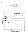
図6、7に、本発明例と比較例について、ナノコンポジット熱電変換材料のフォノン散乱粒子の体積分率と各特性との関係を示す。 6 and 7 show the relationship between the volume fraction of the phonon scattering particles of the nanocomposite thermoelectric conversion material and the characteristics of the present invention example and the comparative example.
まず図6にフォノン散乱粒子の体積率に対して格子熱伝導率をプロットした。体積率は、本発明例0.5〜11vol%、比較例5〜20vol%(粒径5nm)および10〜30vol%(粒径15nm)である。本発明例の代表として実施形態Bの結果を示した(図6、7、8について共通)。 First, in FIG. 6, the lattice thermal conductivity is plotted against the volume fraction of phonon scattering particles. The volume ratios are 0.5 to 11 vol% of inventive examples, 5 to 20 vol% of comparative examples (5 nm particle size), and 10 to 30 vol% (15 nm particle size). The result of Embodiment B is shown as a representative example of the present invention (common to FIGS. 6, 7 and 8).
図中上部の水平破線(「BiSbTe」と付記)は、フォノン散乱粒子を含まないBiSbTe熱電変換材料(本発明のマトリクス材料)のみの場合の格子熱伝導率κphであり、0.90W/m/Kである。 Drawing the horizontal dashed line at the top (the reference character "BiSbTe") is, BiSbTe thermoelectric conversion material containing no phonon scattering particles (matrix material of the present invention) is a lattice thermal conductivity kappa ph cases only, 0.90W / m / K.
これに対して、球状のフォノン散乱粒子(SiO2)が分散している比較例は、フォノン散乱粒子の粒径15nm(体積率10〜30vol%)の場合に格子熱伝導率κphが0.57〜0.52W/m/Kであり、粒径5nm(体積率5〜20vol%)の場合に格子熱伝導率κphが0.34〜0.12W/m/Kであり、フォノン散乱粒子の分散により、大幅に低下している。 On the other hand, in the comparative example in which spherical phonon scattering particles (SiO 2 ) are dispersed, the lattice thermal conductivity κ ph is 0.00 when the particle size of the phonon scattering particles is 15 nm (volume ratio: 10 to 30 vol%). Phonon scattering particles having a lattice thermal conductivity κ ph of 0.34 to 0.12 W / m / K in the case of a particle size of 5 nm (volume ratio of 5 to 20 vol%) when the particle diameter is 57 to 0.52 W / m / K Due to the dispersion of.
更に、多重円弧状のフォノン散乱粒子(体積率0.5〜11vol%)が分散している本発明例は、フォノン散乱粒子体積率の増加に伴い0.5〜0.02W/m/Kと低下の度合いが大きくなっており、少ない体積率で極めて大幅に格子熱伝導率κphが低下している。 Furthermore, the example of the present invention in which multiple arc-shaped phonon scattering particles (volume ratio 0.5 to 11 vol%) are dispersed is 0.5 to 0.02 W / m / K as the phonon scattering particle volume ratio increases. The degree of the decrease is large, and the lattice thermal conductivity κph is extremely greatly decreased with a small volume ratio.
このように本発明によれば、多重円弧形状のフォノン散乱粒子により、フォノン散乱界面が大幅に増大(図3参照)したことにより、格子熱伝導率κphが大幅に低下する。 As described above, according to the present invention, the lattice thermal conductivity κ ph is greatly reduced due to the phonon scattering interface greatly increased (see FIG. 3) due to the multi-arc arc phonon scattering particles.
次に図7に、フォノン散乱粒子の体積率に対して電気伝導率をプロットした。
図中上部の水平破線(「BiSbTe」と付記)は、フォノン散乱粒子を含まないBiSbTe熱電変換材料(本発明のマトリクス材料)のみの場合の電気伝導率σであり、900S/cmである。
Next, in FIG. 7, the electric conductivity is plotted against the volume fraction of the phonon scattering particles.
The horizontal broken line (supplied as “BiSbTe”) at the top of the figure is the electrical conductivity σ in the case of only the BiSbTe thermoelectric conversion material (matrix material of the present invention) that does not contain phonon scattering particles, and is 900 S / cm.
これに対して、球状のフォノン散乱粒子(SiO2、粒径5nm、体積率10〜30vol%)が分散している比較例は、電気伝導率σが、270〜390S/cmであり、多重円弧状のフォノン散乱粒子(体積率0.5〜11vol%)が分散している本発明例は、比較例より高い体積率でフォノン散乱粒子が分散しているにもかかわらず320〜700S/cmと比較例より高い値を示している。
On the other hand, in the comparative example in which spherical phonon scattering particles (SiO 2 ,
この結果は、本発明によれば多重円弧状のフォノン散乱粒子は界面密度が高いにも関わらず、比較例の球状フォノン散乱粒子の場合と同一曲線上の変化となっていると観ることができる。これは、本発明の多重円弧状のフォノン散乱粒子は、トンネル効果(図4(1)(2)参照)により、界面増加によるキャリア散乱の増加(=電気伝導率の低下)が抑制されているためである。 According to the present invention, it can be seen that, according to the present invention, the multi-arc phonon scattering particles have the same curve change as the spherical phonon scattering particles of the comparative example, although the interface density is high. . This is because the multi-arc-shaped phonon scattering particles of the present invention suppress the increase in carrier scattering (= decrease in electrical conductivity) due to the increase in the interface due to the tunnel effect (see FIGS. 4 (1) and (2)). Because.
本発明によれば、多重円弧状のフォノン散乱粒子を分散させて熱伝導率を低減し熱電変換性能を高めたナノコンポジット熱電変換材料を製造する方法が提供される。 According to the present invention, there is provided a method for producing a nanocomposite thermoelectric conversion material in which multiple arc-shaped phonon scattering particles are dispersed to reduce thermal conductivity and to improve thermoelectric conversion performance.
Claims (4)
溶液中で、熱電変換材料を構成する元素を塩の還元により、フォノン散乱粒子を構成する酸化物を前駆体の重合により、それぞれナノ粒子として析出および成長させ、これらナノ粒子の混合物を回収する第1段階、および
上記混合物を水熱処理により合金化して複合ナノ粒子とした後に焼結する第2段階を含み、
上記第1段階において、熱電変換材料を構成する第1群元素のナノ粒子の析出または成長を、フォノン散乱粒子を構成する第2群元素酸化物のナノ粒子の析出または成長よりも先行させることを特徴とするナノコンポジット熱電変換材料の製造方法。 A method for producing a nanocomposite thermoelectric conversion material in which an oxide is dispersed as phonon scattering particles in a matrix of a thermoelectric conversion material,
In the solution, the elements constituting the thermoelectric conversion material are precipitated and grown as nanoparticles by reduction of the salt and the oxides constituting the phonon scattering particles by polymerization of the precursor, respectively, and a mixture of these nanoparticles is recovered. And a second step of sintering the mixture by hydrothermal treatment to form composite nanoparticles,
In the first step, the precipitation or growth of the nanoparticles of the first group element constituting the thermoelectric conversion material is preceded by the precipitation or growth of the nanoparticles of the second group element oxide constituting the phonon scattering particles. A method for producing a nanocomposite thermoelectric conversion material.
上記第1段階は、下記<A><B><C>のいずれかの処理:
<A>下記の工程(1)(2)を順次行う:
(1)下記条件《1》を満たすように、熱電変換材料を構成する第1群元素の塩と、
フォノン散乱粒子を構成する第2群元素酸化物の前駆体との溶液を形成する。
《1》上記溶液中において、同一の還元剤の存在下で、塩が還元されて第1群元
素のナノ粒子が析出する速度が、前駆体が重合して第2群元素酸化物のナノ粒子
が析出する速度より大きくなるように、塩および前駆体を選択する。
(2)上記溶液に還元剤を混合して塩から第1群元素のナノ粒子を析出させるのと同
時に、前駆体の重合により第2群元素酸化物のナノ粒子を析出させ、これらナノ粒子
の混合物を回収する。
または、
<B>下記の工程(1)(2)を順次行う:
(1)下記条件《1》を満たすように、熱電変換材料を構成する第1群元素の塩の第
1溶液およびフォノン散乱粒子を構成する第2群元素酸化物の前駆体の第2溶液をそ
れぞれ形成する。
《1》同一の還元剤の存在下で、塩が還元されて第1群元素のナノ粒子が析出す
る速度が、前駆体が重合して第2群元素酸化物のナノ粒子が析出する速度より大
きくなるように、塩および前駆体を選択する。
(2)第1溶液に還元剤を混合して第1群元素のナノ粒子を析出させた後、第2溶液
を投入し第2群元素酸化物のナノ粒子を析出させ、これらナノ粒子の混合物を回収す
る。
または、
<C>下記の工程(1)(2)を順次行う:
(1)下記条件《1》を満たすように、熱電変換材料を構成する第1群元素の塩の第
1溶液およびフォノン散乱粒子を構成する第2群元素酸化物の前駆体の第2溶液をそ
れぞれ形成する。
《1》同一の還元剤の存在下で、塩が還元されて第1群元素のナノ粒子が析出す
る速度が、前駆体が重合して第2群元素酸化物のナノ粒子が析出する速度より大
きくなるように、塩および前駆体を選択する。
(2)第1溶液に還元剤を混合して第1群元素のナノ粒子を析出させ、静置して凝集
させた後、第2溶液を投入し第2群元素酸化物のナノ粒子を析出させ、これらナノ粒
子の混合物を回収する。
を行い、
次いで、上記第2段階は、下記の工程(3)(4):
(3)上記混合物を水熱処理して第1群元素のナノ粒子と第2群元素酸化物のナノ粒子とを合金化して複合ナノ粒子とする。
(4)上記複合ナノ粒子を焼結してバルク体とする。
を順次行うことを特徴とするナノコンポジット熱電変換材料の製造方法。 In claim 1,
In the first stage, any one of the following <A>, <B>, and <C> processes:
<A> The following steps (1) and (2) are sequentially performed:
(1) a salt of the first group element constituting the thermoelectric conversion material so as to satisfy the following condition << 1 >>
A solution is formed with a precursor of the second group element oxide constituting the phonon scattering particles.
<< 1 >> In the above solution, in the presence of the same reducing agent, the rate at which the salt is reduced and the nanoparticles of the first group element precipitate out is determined by the polymerization of the precursor and the second group element oxide nanoparticle. The salt and precursor are selected to be greater than the rate at which the particles precipitate.
(2) At the same time that the reducing agent is mixed in the above solution to precipitate the first group element nanoparticles from the salt, the second group element oxide nanoparticles are precipitated by polymerization of the precursor, and these nanoparticles The mixture of is recovered.
Or
<B> The following steps (1) and (2) are sequentially performed:
(1) A first solution of a salt of the first group element constituting the thermoelectric conversion material and a second solution of a precursor of the second group element oxide constituting the phonon scattering particles so as to satisfy the following condition << 1 >> Form each one.
<< 1 >> In the presence of the same reducing agent, the rate at which the salt is reduced and the nanoparticles of the first group element are precipitated is the rate at which the precursor is polymerized and the nanoparticles of the second group element oxide are precipitated. Select salts and precursors to be larger.
(2) After the reducing agent is mixed with the first solution to precipitate the first group element nanoparticles, the second solution is added to precipitate the second group element oxide nanoparticles, and the mixture of these nanoparticles. Collect.
Or
<C> The following steps (1) and (2) are sequentially performed:
(1) A first solution of a salt of the first group element constituting the thermoelectric conversion material and a second solution of a precursor of the second group element oxide constituting the phonon scattering particles so as to satisfy the following condition << 1 >> Form each one.
<< 1 >> In the presence of the same reducing agent, the rate at which the salt is reduced and the nanoparticles of the first group element are precipitated is the rate at which the precursor is polymerized and the nanoparticles of the second group element oxide are precipitated. Select salts and precursors to be larger.
(2) A reducing agent is mixed in the first solution to deposit the first group element nanoparticles, and after allowing to stand and aggregate, the second solution is added to deposit the second group element oxide nanoparticles. To collect a mixture of these nanoparticles.
And
Next, the second stage includes the following steps (3) and (4):
(3) The mixture is hydrothermally treated to alloy the first group element nanoparticles and the second group element oxide nanoparticles into composite nanoparticles.
(4) The composite nanoparticles are sintered into a bulk body.
A method for producing a nanocomposite thermoelectric conversion material, characterized by sequentially performing steps.
第1群元素を、Si、Bi、Sb、Te、Seから選択することを特徴とするナノコンポジット熱電変換材料の製造方法。 In claim 1 or 2,
A method for producing a nanocomposite thermoelectric conversion material, wherein the first group element is selected from Si, Bi, Sb, Te, and Se.
第2群元素を、Si、Bi、Sb、Te、Se、Ti、Alから選択することを特徴とするナノコンポジット熱電変換材料の製造方法。 In any one of Claims 1-3,
A method for producing a nanocomposite thermoelectric conversion material, wherein the second group element is selected from Si, Bi, Sb, Te, Se, Ti, and Al.
Priority Applications (5)
| Application Number | Priority Date | Filing Date | Title |
|---|---|---|---|
| JP2013145503A JP5714660B2 (en) | 2013-07-11 | 2013-07-11 | Method for producing nanocomposite thermoelectric conversion material |
| PCT/JP2014/065868 WO2015005065A1 (en) | 2013-07-11 | 2014-06-16 | Method for manufacturing nanocomposite thermoelectric conversion material |
| CN201480003802.6A CN104885242A (en) | 2013-07-11 | 2014-06-16 | Method for manufacturing nanocomposite thermoelectric conversion material |
| DE112014000361.1T DE112014000361T5 (en) | 2013-07-11 | 2014-06-16 | A method of making a thermoelectric nanocomposite conversion material |
| US14/652,306 US20160107239A1 (en) | 2013-07-11 | 2014-06-16 | Method for manufacturing nanocomposite thermoelectric conversion material |
Applications Claiming Priority (1)
| Application Number | Priority Date | Filing Date | Title |
|---|---|---|---|
| JP2013145503A JP5714660B2 (en) | 2013-07-11 | 2013-07-11 | Method for producing nanocomposite thermoelectric conversion material |
Publications (2)
| Publication Number | Publication Date |
|---|---|
| JP2015018954A true JP2015018954A (en) | 2015-01-29 |
| JP5714660B2 JP5714660B2 (en) | 2015-05-07 |
Family
ID=52279754
Family Applications (1)
| Application Number | Title | Priority Date | Filing Date |
|---|---|---|---|
| JP2013145503A Expired - Fee Related JP5714660B2 (en) | 2013-07-11 | 2013-07-11 | Method for producing nanocomposite thermoelectric conversion material |
Country Status (5)
| Country | Link |
|---|---|
| US (1) | US20160107239A1 (en) |
| JP (1) | JP5714660B2 (en) |
| CN (1) | CN104885242A (en) |
| DE (1) | DE112014000361T5 (en) |
| WO (1) | WO2015005065A1 (en) |
Cited By (2)
| Publication number | Priority date | Publication date | Assignee | Title |
|---|---|---|---|---|
| JP2016178251A (en) * | 2015-03-20 | 2016-10-06 | トヨタ自動車株式会社 | Thermoelectric conversion material, method for manufacturing the same, and thermoelectric conversion element arranged by use thereof |
| JP2017014578A (en) * | 2015-07-01 | 2017-01-19 | トヨタ自動車株式会社 | METHOD FOR PRODUCING ALLOY PARTICLES INCLUDING Bi AND Te |
Families Citing this family (1)
| Publication number | Priority date | Publication date | Assignee | Title |
|---|---|---|---|---|
| US20230110366A1 (en) * | 2017-02-16 | 2023-04-13 | Wake Forest University | Composite nanoparticle compositions and assemblies |
Citations (5)
| Publication number | Priority date | Publication date | Assignee | Title |
|---|---|---|---|---|
| JPH06163996A (en) * | 1992-11-20 | 1994-06-10 | Matsushita Electric Ind Co Ltd | Manufacture of thermoelectric material |
| JP2003533363A (en) * | 2000-05-17 | 2003-11-11 | ユニヴァーシティ オヴ フロリダ | Coated nanoparticles |
| JP2011003741A (en) * | 2009-06-18 | 2011-01-06 | Toyota Motor Corp | Nano-composite thermoelectric conversion material, and method of manufacturing the same |
| US20120152294A1 (en) * | 2010-12-17 | 2012-06-21 | Samsung Electronics Co., Ltd. | Thermoelectric material including coating layers, method of preparing the thermoelectric material, and thermoelectric device including the thermoelectric material |
| JP2013074051A (en) * | 2011-09-27 | 2013-04-22 | Toyota Motor Corp | Method of manufacturing nano-composite thermoelectric conversion material, and nano-composite thermoelectric conversion material manufactured by the method |
Family Cites Families (3)
| Publication number | Priority date | Publication date | Assignee | Title |
|---|---|---|---|---|
| CN100546063C (en) * | 2008-02-26 | 2009-09-30 | 杭州电子科技大学 | A kind of preparation method of core-shell structure nano pyroelectric material |
| JP4715953B2 (en) * | 2008-10-10 | 2011-07-06 | トヨタ自動車株式会社 | Nanocomposite thermoelectric conversion material, thermoelectric conversion element using the same, and method for producing nanocomposite thermoelectric conversion material |
| JP5024393B2 (en) * | 2010-01-18 | 2012-09-12 | トヨタ自動車株式会社 | Nanocomposite thermoelectric conversion material and method for producing the same |
-
2013
- 2013-07-11 JP JP2013145503A patent/JP5714660B2/en not_active Expired - Fee Related
-
2014
- 2014-06-16 US US14/652,306 patent/US20160107239A1/en not_active Abandoned
- 2014-06-16 DE DE112014000361.1T patent/DE112014000361T5/en not_active Withdrawn
- 2014-06-16 WO PCT/JP2014/065868 patent/WO2015005065A1/en active Application Filing
- 2014-06-16 CN CN201480003802.6A patent/CN104885242A/en active Pending
Patent Citations (5)
| Publication number | Priority date | Publication date | Assignee | Title |
|---|---|---|---|---|
| JPH06163996A (en) * | 1992-11-20 | 1994-06-10 | Matsushita Electric Ind Co Ltd | Manufacture of thermoelectric material |
| JP2003533363A (en) * | 2000-05-17 | 2003-11-11 | ユニヴァーシティ オヴ フロリダ | Coated nanoparticles |
| JP2011003741A (en) * | 2009-06-18 | 2011-01-06 | Toyota Motor Corp | Nano-composite thermoelectric conversion material, and method of manufacturing the same |
| US20120152294A1 (en) * | 2010-12-17 | 2012-06-21 | Samsung Electronics Co., Ltd. | Thermoelectric material including coating layers, method of preparing the thermoelectric material, and thermoelectric device including the thermoelectric material |
| JP2013074051A (en) * | 2011-09-27 | 2013-04-22 | Toyota Motor Corp | Method of manufacturing nano-composite thermoelectric conversion material, and nano-composite thermoelectric conversion material manufactured by the method |
Non-Patent Citations (2)
| Title |
|---|
| RENJIS T. TOM ET AL.: "Freely Dispersible Au@TiO2, Au@ZiO2, Ag@TiO2, and Ag@ZrO2 Core-Shell Nanoparticles: One-Step Synthes", LANGMUIR, vol. 19, JPN6014039462, 2003, pages 3439 - 3445, XP002586209, ISSN: 0003008747, DOI: 10.1021/la0266435 * |
| YOSHIO KOBAYASHI ET AL.: "Silica coating of silver nanoparticles using a modified Stoeber method", JOURNAL OF COLLOID AND INTERFACE SCIENCE, vol. 283, JPN6014039460, 2005, pages 392 - 396, ISSN: 0003008746 * |
Cited By (2)
| Publication number | Priority date | Publication date | Assignee | Title |
|---|---|---|---|---|
| JP2016178251A (en) * | 2015-03-20 | 2016-10-06 | トヨタ自動車株式会社 | Thermoelectric conversion material, method for manufacturing the same, and thermoelectric conversion element arranged by use thereof |
| JP2017014578A (en) * | 2015-07-01 | 2017-01-19 | トヨタ自動車株式会社 | METHOD FOR PRODUCING ALLOY PARTICLES INCLUDING Bi AND Te |
Also Published As
| Publication number | Publication date |
|---|---|
| WO2015005065A1 (en) | 2015-01-15 |
| DE112014000361T5 (en) | 2015-10-08 |
| JP5714660B2 (en) | 2015-05-07 |
| CN104885242A (en) | 2015-09-02 |
| US20160107239A1 (en) | 2016-04-21 |
Similar Documents
| Publication | Publication Date | Title |
|---|---|---|
| JP5214695B2 (en) | Thermoelectric material, composite material using the same, and method for producing the same | |
| US8333912B2 (en) | Thermoelectric composite material and method of producing the same | |
| JP2018525304A (en) | Aqueous-based method for preparing metal chalcogenide nanomaterials | |
| JP5024393B2 (en) | Nanocomposite thermoelectric conversion material and method for producing the same | |
| JP4803282B2 (en) | Nanocomposite thermoelectric conversion material and method for producing the same | |
| JP2010114419A (en) | Nano-composite thermoelectric conversion material, thermoelectric conversion element using the same, production process of nano-composite thermoelectric conversion material | |
| JP2018521943A (en) | Method for preparing metal chalcogenide nanomaterials | |
| US8535554B2 (en) | High-Ph synthesis of nanocomposite thermoelectric material | |
| JP5714660B2 (en) | Method for producing nanocomposite thermoelectric conversion material | |
| US8641917B2 (en) | Ternary thermoelectric material containing nanoparticles and process for producing the same | |
| JP5149761B2 (en) | BiTe / Ceramics / Nanocomposite Thermoelectric Material Manufacturing Method | |
| JP5702315B2 (en) | Synthesis of nanocomposite thermoelectric materials | |
| JP6189582B2 (en) | Method for producing nanocomposite thermoelectric conversion material | |
| KR101068964B1 (en) | Thermoelectric material and method of manufacturing thermoelectric material by chemical process | |
| CN104953020A (en) | Phonon scattering material, nanocomposite thermoelectric material, and method of producing the same | |
| KR101142917B1 (en) | Method for fabricating thermoelectric nano composition powder | |
| JP5387215B2 (en) | Nanocomposite thermoelectric conversion material and method for producing the same | |
| JP2014165260A (en) | Method of producing thermoelectric conversion material | |
| TWI589039B (en) | N-type bismuth telluride based thermoelectric composite and method for manufacturing the same | |
| KR102064464B1 (en) | Method of manufacturing nanoparticles containing Au, copper core and silica shell | |
| JP6001338B2 (en) | Method for producing nanocomposite thermoelectric conversion material | |
| JP6747828B2 (en) | Thermoelectric conversion material and manufacturing method thereof | |
| JP2014013869A (en) | Nano-composite thermoelectric conversion material and manufacturing method thereof | |
| JP2011129635A (en) | Nano-composite thermoelectric conversion material and method of manufacturing the same | |
| JP5397500B2 (en) | Nanocomposite thermoelectric conversion material and method for producing the same |
Legal Events
| Date | Code | Title | Description |
|---|---|---|---|
| A521 | Request for written amendment filed |
Free format text: JAPANESE INTERMEDIATE CODE: A523 Effective date: 20141117 |
|
| TRDD | Decision of grant or rejection written | ||
| A01 | Written decision to grant a patent or to grant a registration (utility model) |
Free format text: JAPANESE INTERMEDIATE CODE: A01 Effective date: 20150217 |
|
| A61 | First payment of annual fees (during grant procedure) |
Free format text: JAPANESE INTERMEDIATE CODE: A61 Effective date: 20150311 |
|
| LAPS | Cancellation because of no payment of annual fees |