JP2015018794A - Method of manufacturing crimp terminal, and terminal fitting - Google Patents
Method of manufacturing crimp terminal, and terminal fitting Download PDFInfo
- Publication number
- JP2015018794A JP2015018794A JP2014103445A JP2014103445A JP2015018794A JP 2015018794 A JP2015018794 A JP 2015018794A JP 2014103445 A JP2014103445 A JP 2014103445A JP 2014103445 A JP2014103445 A JP 2014103445A JP 2015018794 A JP2015018794 A JP 2015018794A
- Authority
- JP
- Japan
- Prior art keywords
- terminal
- crimping
- equivalent
- bending
- shape
- Prior art date
- Legal status (The legal status is an assumption and is not a legal conclusion. Google has not performed a legal analysis and makes no representation as to the accuracy of the status listed.)
- Granted
Links
Images


Classifications
-
- H—ELECTRICITY
- H01—ELECTRIC ELEMENTS
- H01R—ELECTRICALLY-CONDUCTIVE CONNECTIONS; STRUCTURAL ASSOCIATIONS OF A PLURALITY OF MUTUALLY-INSULATED ELECTRICAL CONNECTING ELEMENTS; COUPLING DEVICES; CURRENT COLLECTORS
- H01R4/00—Electrically-conductive connections between two or more conductive members in direct contact, i.e. touching one another; Means for effecting or maintaining such contact; Electrically-conductive connections having two or more spaced connecting locations for conductors and using contact members penetrating insulation
- H01R4/10—Electrically-conductive connections between two or more conductive members in direct contact, i.e. touching one another; Means for effecting or maintaining such contact; Electrically-conductive connections having two or more spaced connecting locations for conductors and using contact members penetrating insulation effected solely by twisting, wrapping, bending, crimping, or other permanent deformation
- H01R4/18—Electrically-conductive connections between two or more conductive members in direct contact, i.e. touching one another; Means for effecting or maintaining such contact; Electrically-conductive connections having two or more spaced connecting locations for conductors and using contact members penetrating insulation effected solely by twisting, wrapping, bending, crimping, or other permanent deformation by crimping
- H01R4/183—Electrically-conductive connections between two or more conductive members in direct contact, i.e. touching one another; Means for effecting or maintaining such contact; Electrically-conductive connections having two or more spaced connecting locations for conductors and using contact members penetrating insulation effected solely by twisting, wrapping, bending, crimping, or other permanent deformation by crimping for cylindrical elongated bodies, e.g. cables having circular cross-section
-
- H—ELECTRICITY
- H01—ELECTRIC ELEMENTS
- H01R—ELECTRICALLY-CONDUCTIVE CONNECTIONS; STRUCTURAL ASSOCIATIONS OF A PLURALITY OF MUTUALLY-INSULATED ELECTRICAL CONNECTING ELEMENTS; COUPLING DEVICES; CURRENT COLLECTORS
- H01R43/00—Apparatus or processes specially adapted for manufacturing, assembling, maintaining, or repairing of line connectors or current collectors or for joining electric conductors
- H01R43/16—Apparatus or processes specially adapted for manufacturing, assembling, maintaining, or repairing of line connectors or current collectors or for joining electric conductors for manufacturing contact members, e.g. by punching and by bending
-
- H—ELECTRICITY
- H01—ELECTRIC ELEMENTS
- H01R—ELECTRICALLY-CONDUCTIVE CONNECTIONS; STRUCTURAL ASSOCIATIONS OF A PLURALITY OF MUTUALLY-INSULATED ELECTRICAL CONNECTING ELEMENTS; COUPLING DEVICES; CURRENT COLLECTORS
- H01R13/00—Details of coupling devices of the kinds covered by groups H01R12/70 or H01R24/00 - H01R33/00
- H01R13/46—Bases; Cases
- H01R13/52—Dustproof, splashproof, drip-proof, waterproof, or flameproof cases
- H01R13/5219—Sealing means between coupling parts, e.g. interfacial seal
- H01R13/5221—Sealing means between coupling parts, e.g. interfacial seal having cable sealing means
-
- H—ELECTRICITY
- H01—ELECTRIC ELEMENTS
- H01R—ELECTRICALLY-CONDUCTIVE CONNECTIONS; STRUCTURAL ASSOCIATIONS OF A PLURALITY OF MUTUALLY-INSULATED ELECTRICAL CONNECTING ELEMENTS; COUPLING DEVICES; CURRENT COLLECTORS
- H01R4/00—Electrically-conductive connections between two or more conductive members in direct contact, i.e. touching one another; Means for effecting or maintaining such contact; Electrically-conductive connections having two or more spaced connecting locations for conductors and using contact members penetrating insulation
- H01R4/10—Electrically-conductive connections between two or more conductive members in direct contact, i.e. touching one another; Means for effecting or maintaining such contact; Electrically-conductive connections having two or more spaced connecting locations for conductors and using contact members penetrating insulation effected solely by twisting, wrapping, bending, crimping, or other permanent deformation
- H01R4/18—Electrically-conductive connections between two or more conductive members in direct contact, i.e. touching one another; Means for effecting or maintaining such contact; Electrically-conductive connections having two or more spaced connecting locations for conductors and using contact members penetrating insulation effected solely by twisting, wrapping, bending, crimping, or other permanent deformation by crimping
- H01R4/187—Electrically-conductive connections between two or more conductive members in direct contact, i.e. touching one another; Means for effecting or maintaining such contact; Electrically-conductive connections having two or more spaced connecting locations for conductors and using contact members penetrating insulation effected solely by twisting, wrapping, bending, crimping, or other permanent deformation by crimping combined with soldering or welding
-
- H—ELECTRICITY
- H01—ELECTRIC ELEMENTS
- H01R—ELECTRICALLY-CONDUCTIVE CONNECTIONS; STRUCTURAL ASSOCIATIONS OF A PLURALITY OF MUTUALLY-INSULATED ELECTRICAL CONNECTING ELEMENTS; COUPLING DEVICES; CURRENT COLLECTORS
- H01R43/00—Apparatus or processes specially adapted for manufacturing, assembling, maintaining, or repairing of line connectors or current collectors or for joining electric conductors
- H01R43/02—Apparatus or processes specially adapted for manufacturing, assembling, maintaining, or repairing of line connectors or current collectors or for joining electric conductors for soldered or welded connections
-
- H—ELECTRICITY
- H01—ELECTRIC ELEMENTS
- H01R—ELECTRICALLY-CONDUCTIVE CONNECTIONS; STRUCTURAL ASSOCIATIONS OF A PLURALITY OF MUTUALLY-INSULATED ELECTRICAL CONNECTING ELEMENTS; COUPLING DEVICES; CURRENT COLLECTORS
- H01R43/00—Apparatus or processes specially adapted for manufacturing, assembling, maintaining, or repairing of line connectors or current collectors or for joining electric conductors
- H01R43/04—Apparatus or processes specially adapted for manufacturing, assembling, maintaining, or repairing of line connectors or current collectors or for joining electric conductors for forming connections by deformation, e.g. crimping tool
- H01R43/048—Crimping apparatus or processes
- H01R43/05—Crimping apparatus or processes with wire-insulation stripping
-
- H—ELECTRICITY
- H01—ELECTRIC ELEMENTS
- H01R—ELECTRICALLY-CONDUCTIVE CONNECTIONS; STRUCTURAL ASSOCIATIONS OF A PLURALITY OF MUTUALLY-INSULATED ELECTRICAL CONNECTING ELEMENTS; COUPLING DEVICES; CURRENT COLLECTORS
- H01R4/00—Electrically-conductive connections between two or more conductive members in direct contact, i.e. touching one another; Means for effecting or maintaining such contact; Electrically-conductive connections having two or more spaced connecting locations for conductors and using contact members penetrating insulation
- H01R4/58—Electrically-conductive connections between two or more conductive members in direct contact, i.e. touching one another; Means for effecting or maintaining such contact; Electrically-conductive connections having two or more spaced connecting locations for conductors and using contact members penetrating insulation characterised by the form or material of the contacting members
- H01R4/62—Connections between conductors of different materials; Connections between or with aluminium or steel-core aluminium conductors
-
- H—ELECTRICITY
- H01—ELECTRIC ELEMENTS
- H01R—ELECTRICALLY-CONDUCTIVE CONNECTIONS; STRUCTURAL ASSOCIATIONS OF A PLURALITY OF MUTUALLY-INSULATED ELECTRICAL CONNECTING ELEMENTS; COUPLING DEVICES; CURRENT COLLECTORS
- H01R43/00—Apparatus or processes specially adapted for manufacturing, assembling, maintaining, or repairing of line connectors or current collectors or for joining electric conductors
- H01R43/04—Apparatus or processes specially adapted for manufacturing, assembling, maintaining, or repairing of line connectors or current collectors or for joining electric conductors for forming connections by deformation, e.g. crimping tool
- H01R43/048—Crimping apparatus or processes
Abstract
Description
この発明は、板状の端子基材を、端子形状へ曲げ加工する端子曲げ加工工程において、導体を絶縁被覆で被覆した被覆電線における少なくとも先端側の前記絶縁被覆を剥離した導体先端部をかしめて圧着する圧着部に相当する箇所である、前記板状の端子基材における圧着箇所相当部を、未加工形状から筒状の圧着部として曲げ加工して製造する圧着端子、該圧着端子の製造方法、該圧着端子の製造装置に関する。 In the terminal bending process of bending a plate-shaped terminal base material into a terminal shape, the present invention caulks the conductor tip part from which at least the tip side insulation coating is peeled off in the coated electric wire in which the conductor is coated with the insulation coating. A crimping terminal that is a part corresponding to a crimping part to be crimped, which is produced by bending a crimping part equivalent part in the plate-like terminal base material from a non-processed shape into a cylindrical crimping part, and a method for producing the crimping terminal The present invention relates to a crimp terminal manufacturing apparatus.
圧着端子は、帯状に形成されたキャリアを備えた端子連結帯を板状の端子基材から打ち抜いて形成した端子連結帯をキャリア長手方向に沿って間欠的に送りながらキャリアの幅方向の少なくとも一端側から突出する端子金具に対して、適宜の曲げ加工工程を経て端子形状に加工し、該端子金具をキャリアに対して切断することで製造する。例えば、特許文献1に開示の「金型装置及び金型装置を用いた加工方法」もその一つである。
At least one end in the width direction of the carrier while the terminal connection band formed by punching a terminal connection band provided with a carrier formed in a band shape from a plate-shaped terminal base material is intermittently sent along the carrier longitudinal direction. The terminal fitting protruding from the side is processed into a terminal shape through an appropriate bending process, and is manufactured by cutting the terminal fitting with respect to the carrier. For example, “a mold apparatus and a processing method using the mold apparatus” disclosed in
ところで、上述した圧着端子には、被覆電線に圧着する圧着部の形態に応じてオープンバレル型のものとクローズドバレル型のものがある。 By the way, in the crimp terminal mentioned above, there are an open barrel type and a closed barrel type depending on the form of the crimp part to be crimped to the covered electric wire.
オープンバレル型の圧着端子の圧着部は、特許文献1に開示のバレルのように、上方が開放された縦断面略U字形に形成されている。被覆電線の先端に対する接続に際しては、導体を剥き出しにした被覆電線の導体先端部を圧着部に配置した後、圧着部を、被覆電線の先端側の少なくとも導体先端部に圧着する。
The crimp portion of the open barrel-type crimp terminal is formed in a substantially U-shaped longitudinal section with the top opened, like the barrel disclosed in
クローズドバレル型の圧着端子の圧着部は、導体先端部を圧着部に挿入したのち、圧着部を縮径方向に塑性変形して圧着できるように、筒状に形成されている。 The crimping portion of the closed barrel type crimp terminal is formed in a cylindrical shape so that the crimping portion can be plastically deformed in the reduced diameter direction after the conductor tip portion is inserted into the crimping portion.
このようなクローズドバレル型の圧着端子は、筒状の圧着部の内部に挿入した状態で圧着した導体先端部を外周全体で囲繞することができるため、水分等の外的要因から導体先端部をしっかりと保護することができるという圧着部が筒状であるが故の優れた特性を有している。
このような優れた特性を有する筒状の圧着部の高い信頼性を保つために、圧着部を、確実に、且つ容易に筒状に加工する必要があった。
Such a closed barrel type crimp terminal can surround the conductor tip part crimped in a state of being inserted into the inside of the cylindrical crimp part over the entire outer periphery, so that the conductor tip part can be removed from external factors such as moisture. The crimping part that can be securely protected has a superior characteristic because it is cylindrical.
In order to maintain the high reliability of the cylindrical pressure-bonding part having such excellent characteristics, it is necessary to reliably and easily process the pressure-bonding part into a cylindrical shape.
そこで、この発明は、筒状に曲げ加工する曲げ加工箇所における対向端部同士が対向する対向部分を確実に溶接可能な状態に該対向端部同士を対向させることができる筒状体、圧着部を備えた圧着端子、及びこれらの製造方法、並びに圧着端子の製造装置を提供することを目的とする。 In view of this, the present invention provides a cylindrical body and a crimping portion that can be opposed to each other in such a manner that the opposed portions facing each other at the bending portions to be bent into a tubular shape can be reliably welded. It is an object of the present invention to provide a crimp terminal, a manufacturing method thereof, and a crimp terminal manufacturing apparatus.
この発明は、板材における少なくとも一部の曲げ加工箇所を未加工形状から筒状に曲げ加工する筒状体の製造方法であって、前記曲げ加工箇所の幅方向の少なくとも一部を、前記未加工形状から前記所定の曲げ加工形状に塑性変形させる曲げ率よりも高い曲げ率で曲げ加工する高曲げ率加工工程と、前記高曲げ率加工工程で加工した前記曲げ加工箇所を、筒状へ整形させる整形工程とを、この順で行うことを特徴とする。 The present invention relates to a method of manufacturing a cylindrical body in which at least a part of a bent portion of a plate material is bent from an unprocessed shape into a tubular shape, and at least a part of the bent portion in the width direction is processed into the unprocessed portion. A high bending rate processing step for bending at a bending rate higher than a bending rate for plastic deformation from a shape to the predetermined bending shape, and the bending portion processed in the high bending rate processing step are shaped into a cylinder. The shaping step is performed in this order.
上述した構成によれば、対向端部同士が突き合わさった突合せ部分において端部同士の隙間が不測に生じることがなく、確実に筒状の形状に保つことができる曲げ加工箇所を備えた筒状体を提供することができる。 According to the above-described configuration, a cylindrical shape provided with a bending portion that can reliably maintain a cylindrical shape without causing a gap between the end portions unexpectedly in the abutting portion where the opposing end portions abut each other. The body can be provided.
詳述すると、前記曲げ加工箇所を単純に筒状に曲げ加工した場合、曲げ加工箇所の厚み方向の外側部分には、内部応力として圧縮力(引張力の反力)が作用するとともに、内側部分には、引張力(圧縮力の反力)が作用し、曲げ加工後においても曲げ加工箇所においては、このような応力が残留することになる。 More specifically, when the bent portion is simply bent into a cylindrical shape, a compressive force (reaction force of tensile force) acts as an internal stress on the outer portion in the thickness direction of the bent portion, and an inner portion. In this case, a tensile force (reaction force of the compressive force) acts, and such a stress remains in the bent portion even after the bending.
そうすると、曲げ加工前の形状に復元しようとする内部応力が曲げ加工箇所に作用することになり、曲げ加工箇所の対向端部同士が突き合わさった突合せ部分において端部同士の間に隙間が不測に生じるなど、曲げ加工後の筒状の形状に留めておくことができなかった。 If it does so, the internal stress which is going to restore to the shape before bending will act on a bending part, and a gap will be unexpectedly formed between the ends in the abutting part where opposite ends of the bending part are abutted. For example, it could not be kept in a cylindrical shape after bending.
これに対して、高曲げ率加工工程を行うことで、前記曲げ加工箇所における厚み方向の外側部分においては、内部応力が作用しない状態、或いは周方向の外側へ引っ張る引張り力、すなわち圧縮力に対する反力を作用させることができる。 On the other hand, by performing a high bending rate processing step, in the outer portion in the thickness direction at the bending portion, the internal stress is not applied, or the tensile force pulling outward in the circumferential direction, that is, the reaction against the compressive force. Force can be applied.
さらに、前記曲げ加工箇所における厚み方向の内側部分においては、内部応力が作用しない状態、或いは周方向の内側へ圧縮する圧縮力、すなわち引っ張り力に対する反力を作用させることができる。 Furthermore, in the inner portion in the thickness direction at the bending portion, a state in which no internal stress is applied, or a compressive force that compresses inward in the circumferential direction, that is, a reaction force against a tensile force, can be applied.
従って、対向端部同士が突き合わさった突合せ部分において端部同士の間に隙間が不測に生じることがなく、曲げ加工後の曲げ加工箇所を、確実に筒状の形状に保つことができる。 Therefore, a gap is not unexpectedly generated between the end portions where the opposing end portions are abutted with each other, and the bent portion after bending can be reliably maintained in a cylindrical shape.
前記筒状体は、前記板材における少なくとも一部の曲げ加工箇所を未加工形状から筒状に曲げ加工して、筒状の形状に保つ必要がある部材であれば特に限定せず、例えば、後述する圧着端子が好適である。 The cylindrical body is not particularly limited as long as it is a member that needs to bend a cylindrical portion from an unprocessed shape into a cylindrical shape by bending at least a part of the plate material, for example, described later. A crimp terminal is preferred.
またこの発明は、導体を絶縁被覆で被覆した被覆電線における少なくとも先端側の前記絶縁被覆を剥離した導体先端部を圧着する筒状の圧着部を備えた圧着端子を製造する圧着端子の製造方法であって、上述した筒状体を、前記圧着端子で形成し、上述した板材を、曲げ加工前の前記圧着部に相当する圧着箇所相当部を備えた板状の端子基材で形成し、上述した曲げ加工箇所を、前記圧着箇所相当部で形成し、前記端子基材における少なくとも前記圧着箇所相当部を未加工形状から前記筒状に曲げ加工するに伴って、前記圧着箇所相当部における、所定の曲げ加工形状に塑性変形させる変形箇所の少なくとも一部を、前記未加工形状から前記所定の曲げ加工形状に塑性変形させる曲げ率よりも高い曲げ率で曲げ加工する高曲げ率加工工程と、
前記高曲げ率加工工程で加工した前記圧着箇所相当部を、筒状の前記圧着部へ整形させる整形工程とを、この順で行うことを特徴とする。
The present invention also relates to a method of manufacturing a crimp terminal comprising a crimped terminal provided with a cylindrical crimp part for crimping a conductor tip part from which at least the tip side insulation coating has been peeled off in a coated electric wire having a conductor coated with an insulation coating. Then, the above-described cylindrical body is formed by the crimp terminal, and the above-described plate material is formed by a plate-like terminal base material provided with a crimp-corresponding portion equivalent portion corresponding to the crimp portion before bending. Forming the bent portion at the crimping portion equivalent portion, and bending the at least the crimping portion equivalent portion of the terminal base material from the unprocessed shape into the cylindrical shape. A high bending rate processing step of bending at least a part of the deformation portion to be plastically deformed into a bending shape of the material at a bending rate higher than a bending rate to plastically deform from the unprocessed shape to the predetermined bending shape;
A shaping step of shaping the crimped portion corresponding portion machined in the high bending rate machining step into the cylindrical crimped portion is performed in this order.
上述した構成によれば、前記圧着箇所相当部を前記未加工形状から直接、前記筒状に曲げ加工するのではなく、前記高曲げ率加工工程において、前記圧着箇所相当部における前記変形箇所の少なくとも一部を、前記未加工形状から前記所定の曲げ加工形状に塑性変形させる曲げ率よりも高い曲げ率で曲げ加工を行う。 According to the above-described configuration, at least the deformation portion in the crimping portion corresponding portion is not bent in the cylindrical shape directly from the unprocessed shape in the high bending rate machining step. A part is bent at a bending rate higher than a bending rate for plastic deformation from the unprocessed shape to the predetermined bent shape.
この状態で、前記端子曲げ加工工程によって最終的に加工しようとしていた筒状の前記圧着部となるように、整形工程を行うことで、前記圧着箇所相当部を曲げ加工する曲げ率によっては、圧着部における対向部分に、該対向端部同士が互いに密着しようとする内向きの力を発生させることができ、対向端部同士が押し合うように突き合わせることができる。 In this state, depending on the bending rate at which the portion corresponding to the crimping portion is bent by performing a shaping step so as to be the cylindrical crimping portion that was finally processed by the terminal bending step, An inward force in which the opposing end portions are in close contact with each other can be generated at the opposing portion of the portion, and the opposing end portions can be abutted against each other.
すなわち、前記圧着部が前記所定の加工形状から前記未加工形状へ復元しようとして対向端部同士が離間しようとする外向きの力を解消することができる。 That is, it is possible to eliminate the outward force that the opposing end portions try to separate from each other as the crimping portion tries to restore from the predetermined processed shape to the unprocessed shape.
従って、筒状に曲げ加工した圧着部における対向端部同士が対向する対向部分に隙間が生じることがなく、又は対向端部同士を溶接可能な隙間に留めておくことができるため、該対向部分を確実に溶接することができる。 Accordingly, there is no gap in the facing portion where the facing ends of the crimped portion bent into a cylindrical shape face each other, or the facing ends can be kept in a weldable gap. Can be reliably welded.
なお、前記変形箇所の少なくとも一部に対して行う前記高曲げ率加工工程は、圧着部の周方向において対向する対向端部同士を積極的に密着させる内向きの力が生じる方向の内部応力が残留する程度の曲げ率で加工することが好ましいがこれに限らず、単に、対向端部同士が離間しようとする外向きの力を抑制する程度の曲げ率で加工することも含むものとする。 Note that the high bending rate processing step performed on at least a part of the deformed portion has an internal stress in a direction in which an inward force that positively contacts the opposing end portions facing each other in the circumferential direction of the crimping portion is generated. It is preferable to perform the processing with a bending rate that remains, but the processing is not limited to this, and the processing includes simply processing with a bending rate that suppresses an outward force that the opposing ends tend to separate from each other.
すなわち、少なくとも周方向において対向する対向端部同士が離間する方向の内部応力が作用しなければ、対向端部同士が離間する方向の内部応力を抑制する程度の力が作用していれば必ずしも周方向において対向する対向端部同士が積極的に密着する内部応力が作用していない場合も含むものとする。 In other words, at least if there is no internal stress acting in the direction in which the opposed ends facing each other in the circumferential direction are separated, it is not always necessary if a force is applied to suppress the internal stress in the direction separating the opposed ends. It also includes the case where the internal stress where the opposing end portions facing each other in the direction are in close contact is not acting.
高曲げ率加工工程において曲げ加工する前記曲げ率は、前記未加工形状から前記所定の曲げ加工形状に塑性変形させる曲げ率よりも高い曲げ率であれば特に限定せず、例えば、板状の端子基材の材質、板厚、曲げ加工する際の曲げ力、曲げ半径に応じて決定することができる。 The bending rate for bending in the high bending rate processing step is not particularly limited as long as the bending rate is higher than the bending rate for plastic deformation from the unprocessed shape to the predetermined bending shape. For example, a plate-shaped terminal It can be determined according to the material of the substrate, the plate thickness, the bending force when bending, and the bending radius.
前記所定の曲げ加工形状とは、前記圧着箇所相当部を前記端子曲げ加工工程により塑性変形させた前記変形箇所の最終形状を示す。 The predetermined bending shape indicates the final shape of the deformed portion obtained by plastically deforming the crimped portion corresponding portion by the terminal bending step.
前記未加工形状とは、前記圧着箇所相当部を筒状に曲げ加工する前の該圧着箇所相当部の形状を示し、例えば、平坦形状を示す。 The unprocessed shape refers to the shape of the crimping portion equivalent portion before the crimping portion corresponding portion is bent into a cylindrical shape, for example, a flat shape.
前記圧着部は、長手方向に対して直交する直交断面が正円形状、楕円形状、多角形状など、筒状であれば特に限定しない。 The pressure-bonding part is not particularly limited as long as the orthogonal cross section orthogonal to the longitudinal direction has a cylindrical shape such as a perfect circle shape, an elliptical shape, or a polygonal shape.
前記圧着箇所相当部における前記変形箇所は、前記圧着箇所相当部の端子軸方向に直交する直交方向の全体であっても、複数に亘る箇所であってもよく、前記圧着箇所相当部における少なくとも一部であれば特に限定しない。 The deformation part in the crimping part equivalent part may be the whole of the orthogonal direction orthogonal to the terminal axis direction of the crimping part equivalent part or a plurality of places, and at least one in the crimping part equivalent part. If it is a part, it will not specifically limit.
同様に、前記変形箇所において前記高曲げ率加工工程を行う箇所は、前記変形箇所の端子軸方向に直交する直交方向における全体であっても、複数に亘る箇所であってもよく、前記変形箇所の少なくとも一部であれば特に限定しない。 Similarly, the portion where the high bending rate machining step is performed in the deformed portion may be the entire portion in the orthogonal direction orthogonal to the terminal axis direction of the deformed portion, or may be a plurality of portions. If it is at least a part of, it will not specifically limit.
前記導体は、素線を撚った撚線あるいは単線とすることができ、また、例えば、アルミニウムやアルミニウム合金からなるアルミニウム系導体で形成するなどして、圧着端子を構成する金属に対して卑な金属である異種金属で構成することができるが、これに限らず、例えば、銅や銅合金からなる銅系導体で形成するなどして、圧着端子と同系金属で構成してもよい。 The conductor may be a stranded wire or a single wire obtained by twisting a strand, and may be formed of an aluminum-based conductor made of aluminum or an aluminum alloy, for example, so that the conductor is a base. However, the present invention is not limited to this. For example, it may be formed of a copper-based conductor made of copper or a copper alloy, and may be formed of the same metal as the crimp terminal.
この発明の態様として、前記変形箇所を、前記圧着箇所相当部の端子軸方向に直交する直交方向の全体に設定し、前記整形工程において、前記高曲げ率加工工程で加工した前記圧着箇所相当部を、端子軸方向に直交する直交断面が円形状になるように整形させて加工することができる。 As an aspect of the present invention, the deformed portion is set in the entire orthogonal direction orthogonal to the terminal axis direction of the crimp portion corresponding portion, and the crimp portion corresponding portion processed in the high bending rate processing step in the shaping step. Can be shaped and processed so that the orthogonal cross section orthogonal to the terminal axis direction is circular.
上述した構成によれば、周方向における対向端部同士が互いに離間する方向の内部応力を解消した円筒状の圧着部を備えた圧着端子を製造することができる。 According to the configuration described above, it is possible to manufacture a crimp terminal including a cylindrical crimp portion in which internal stress in a direction in which opposed end portions in the circumferential direction are separated from each other.
前記整形工程において、前記圧着箇所相当部を、前記直交断面が円形状になるように整形させて加工する方法は特に限定せず、例えば、円柱状の芯棒に、前記圧着箇所相当部を巻き付けるようにして整形することができる。 In the shaping step, there is no particular limitation on the method of shaping the crimped portion equivalent portion so that the orthogonal cross section is circular, and for example, the crimped portion equivalent portion is wound around a cylindrical core rod. Can be shaped in this way.
前記整形工程において、一種類の曲げ率の治具を用いて一度に、前記圧着箇所相当部を、円筒状の圧着部に整形するに限らず、曲げ率に応じた複数の治具を用いて複数回に亘って段階的に行ってもよい。 In the shaping step, using a jig with one kind of bending rate at a time, not only shaping the crimping portion corresponding portion into a cylindrical crimping portion, but using a plurality of jigs according to the bending rate. You may carry out in steps over multiple times.
またこの発明の態様として、前記変形箇所の少なくとも一部を、前記圧着箇所相当部における端子軸方向に直交する直交方向の中間部分に設定し、前記高曲げ率加工工程において、前記中間部分を、前記未加工形状から前記所定の曲げ加工形状に塑性変形させる曲げ率よりも高い曲げ率になるように曲げ加工することができる。 Further, as an aspect of the present invention, at least a part of the deformed portion is set to an intermediate portion in an orthogonal direction orthogonal to the terminal axis direction in the crimping portion corresponding portion, and in the high bending rate processing step, the intermediate portion is The bending can be performed so that the bending rate is higher than the bending rate for plastic deformation from the unprocessed shape to the predetermined bending shape.
上述した構成によれば、前記変形箇所の少なくとも一部を、前記圧着箇所相当部の前記直交方向の中間部分に設定することで、高い曲げ率で加工した箇所となる前記中間部分に対して一方側と他方側とを、同じ長さとすることができる。 According to the configuration described above, by setting at least a part of the deformed portion as an intermediate portion in the orthogonal direction of the crimp-corresponding portion corresponding portion, one side with respect to the intermediate portion that becomes a portion processed at a high bending rate. The side and the other side can be the same length.
これにより、整形工程において、圧着箇所相当部を、円筒状に整形させる際に、例えば、高い曲げ率で加工した箇所に対して一方側と他方側とがそれぞれ異なる長さである場合と比較して、一方側部分と他方側部分とをバランスよく円弧状に整形できるため、円筒状に整形した際に、圧着部の対向部分において一対の対向端部のそれぞれにおいて、略同じ大きさの内向きの力を発生させることができ、一対の対向端部が押し合う力を互いにバランスよく作用させることができる。 Thereby, in the shaping process, when the crimped portion corresponding portion is shaped into a cylindrical shape, for example, compared with a case where one side and the other side have different lengths with respect to a portion processed at a high bending rate. Since the one side portion and the other side portion can be shaped into an arc shape in a balanced manner, when shaped into a cylindrical shape, each of the pair of opposed end portions of the crimped portion faces substantially inward. Force can be generated, and the force of pressing the pair of opposed end portions can be applied in a balanced manner.
またこの発明の態様として、前記端子基材に、圧着箇所相当部に対して端子軸方向の先端側で連設するトランジション相当部備え、前記高曲げ率加工工程の前に、前記圧着箇所相当部の幅方向の端部を立ち上げるとともに、前記圧着箇所相当部の立ち上げ方向と同方向にトランジション相当部を立ち上げる端部立ち上げ工程を行い、前記圧着箇所相当部、及び前記トランジション相当部の端部立ち上げと同時に、前記トランジション相当部を底上げする底上げ工程を行い、前記底上げ工程の後に、前記トランジション相当部における前記圧着部との連通箇所に備えた封止箇所相当部を、前記圧着箇所相当部の筒状への曲げ加工とともに筒状に曲げ加工を行うことができる。 Further, as an aspect of the present invention, the terminal base material is provided with a transition equivalent portion continuously provided on the distal end side in the terminal axis direction with respect to the crimping portion corresponding portion, and before the high bending rate processing step, the crimping portion corresponding portion. The end portion in the width direction is raised, and an end raising step of raising the transition equivalent portion in the same direction as the rising direction of the crimping portion corresponding portion is performed, and the crimping portion corresponding portion and the transition corresponding portion are At the same time that the end portion is raised, a bottom raising step of raising the transition equivalent portion is performed, and after the bottom raising step, a sealing portion equivalent portion provided in a communication portion with the crimp portion in the transition equivalent portion Bending can be performed in a cylindrical shape along with bending the corresponding portion into a cylindrical shape.
またこの発明の態様として、前記高曲げ率加工工程と前記整形工程とのうち少なくとも一方の工程において、前記圧着箇所相当部の幅方向の端部同士を周方向において近接させた後に、前記圧着箇所相当部の内部に芯棒を挿入する工程と、
芯棒を挿入した状態の前記圧着箇所相当部を押圧型で押圧する工程とを行うことができる。
Further, as an aspect of the present invention, in at least one of the high bending rate processing step and the shaping step, after the end portions in the width direction of the crimping portion corresponding portions are brought close to each other in the circumferential direction, the crimping portion Inserting a core rod into the corresponding part;
And a step of pressing the portion corresponding to the crimping portion with the core rod inserted with a pressing die.
またこの発明の態様として、前記芯棒の断面が円形であり、前記整形工程において、前記芯棒が挿入された前記圧着箇所相当部を押圧型で外側から押圧する工程によって筒状の圧着部を形成することができる。 Further, as an aspect of the present invention, a cross-section of the core rod is circular, and in the shaping step, a cylindrical crimping portion is formed by pressing the portion corresponding to the crimping portion into which the core rod is inserted from the outside with a pressing die. Can be formed.
またこの発明の態様として、前記封止箇所相当部を厚み方向に押し潰して偏平形状の封止部として形成することができる。 Moreover, as an aspect of this invention, the said sealing location equivalent part can be crushed in the thickness direction, and it can form as a flat-shaped sealing part.
またこの発明の態様として、前記整形工程の後に、前記圧着部の周方向における両端部同士を端子軸方向に沿って高エネルギー密度熱源により溶接する溶接工程を行うことができる。 As an aspect of the present invention, after the shaping step, a welding step of welding both ends in the circumferential direction of the crimping portion along the terminal axis direction with a high energy density heat source can be performed.
上述した圧着端子の製造方法によれば、溶接工程において、前記圧着部の周方向の対向端部同士を端子軸方向に沿って高エネルギー密度熱源により溶接することで、スムーズ、且つ、確実に固着することができる。 According to the above-described method for manufacturing a crimp terminal, in the welding process, the opposing ends in the circumferential direction of the crimp part are welded together with a high energy density heat source along the terminal axis direction, thereby ensuring smooth and reliable fixing. can do.
圧着部に挿入した導体先端部を該圧着部により隙間なく囲繞した状態で導体先端部と圧着部とで圧着することができ、優れた止水性を得ることができる。 The conductor tip portion inserted into the crimping portion can be crimped by the conductor tip portion and the crimping portion in a state where the conductor tip portion is surrounded by the crimping portion without any gap, and excellent water stoppage can be obtained.
ここで、前記高エネルギー密度熱源により溶接するとは、例えば、レーザー、電子ビーム、或いはプラズマにより溶接することを示す。 Here, welding with the high energy density heat source indicates welding with a laser, an electron beam, or plasma, for example.
特に、レーザーの中でもファイバーレーザー溶接は、他のレーザ溶接と比べ、焦点を極小なスポットに合わせることができ、高出力なレーザ溶接を実現することができるとともに、連続照射可能である点で好ましい。 In particular, among lasers, fiber laser welding is preferable compared to other laser welding because the focal point can be adjusted to a minimum spot, high-power laser welding can be realized, and continuous irradiation is possible.
この発明は、導体を絶縁被覆で被覆した被覆電線における少なくとも先端側の前記絶縁被覆を剥離した導体先端部を圧着する筒状の圧着部を備えた圧着端子を製造する圧着端子の製造装置であって、板状の端子基材における前記圧着部に相当する圧着箇所相当部を未加工形状から前記筒状に曲げ加工するに伴って、前記圧着箇所相当部における、所定の曲げ加工形状に塑性変形させる変形箇所の少なくとも一部を、前記未加工形状から前記所定の曲げ加工形状に塑性変形させる曲げ率よりも高い曲げ率で曲げ加工する高曲げ率加工治具と、前記高曲げ率加工治具で曲げ加工した前記圧着箇所相当部を、筒状の前記圧着部へ整形させる整形治具とを備えたことを特徴とする。 The present invention is a crimp terminal manufacturing apparatus that manufactures a crimp terminal including a cylindrical crimp portion that crimps a conductor tip portion from which at least the tip end insulation coating is peeled in a coated electric wire in which a conductor is coated with an insulation coating. As the crimped portion corresponding to the crimped portion of the plate-shaped terminal base material is bent from an unprocessed shape into the cylindrical shape, the plastic deformation to a predetermined bent shape at the crimped portion corresponding portion is performed. A high bending rate processing jig for bending at least a part of the deformed portion at a bending rate higher than a bending rate for plastic deformation from the unprocessed shape to the predetermined bending shape, and the high bending rate processing jig And a shaping jig for shaping the crimped portion corresponding to the crimped portion into a cylindrical crimped portion.
前記高曲げ率加工治具と前記整形治具には、それぞれ前記圧着箇所相当部をプレス加工する治具に限らず、前記圧着箇所相当部を巻き付けて曲げ加工する芯棒などの治具を備えた構成であってもよい。 The high bending rate processing jig and the shaping jig are not limited to a jig that presses the portion corresponding to the crimping portion, but includes a jig such as a core rod that is wound by bending the portion corresponding to the crimping portion. It may be a configuration.
この発明の態様として、前記変形箇所を、前記圧着箇所相当部の端子軸方向に直交する直交方向の全体に設定し、前記整形治具により、前記高曲げ率加工治具で加工した前記圧着箇所相当部を、端子軸方向に直交する直交断面が円形状になるように整形させて加工することができる。 As an aspect of the present invention, the deformed portion is set in the entire orthogonal direction perpendicular to the terminal axis direction of the crimped portion corresponding portion, and the crimped portion processed by the high bending rate processing jig by the shaping jig. The corresponding portion can be processed by shaping so that the orthogonal cross section orthogonal to the terminal axis direction has a circular shape.
前記圧着部は、例えば、円柱状の芯棒に、前記圧着箇所相当部を巻き付けるようにして整形することができる。 The said crimping | compression-bonding part can be shape | molded, for example so that the said crimping | compression-bonding location equivalent part may be wound around a cylindrical core rod.
前記整形工程において、前記筒状の圧着部へ整形させるための工程を一種類の曲げ率の治具を用いて一度で行うに限らず、曲げ率に応じた複数の治具を用いて複数回に亘って段階的に行ってもよい。 In the shaping step, the step for shaping the cylindrical crimping part is not limited to one time using a single bending rate jig, but multiple times using a plurality of jigs according to the bending rate. May be performed step by step.
またこの発明の態様として、前記変形箇所の少なくとも一部を、前記圧着箇所相当部の前記直交方向の中間部分に設定し、前記中間部分を、前記未加工形状から前記所定の曲げ加工形状に塑性変形させる曲げ率よりも高い曲げ率になるように前記高曲げ率加工治具により曲げ加工することができる。 As an aspect of the present invention, at least a part of the deformed portion is set as an intermediate portion in the orthogonal direction of the crimped portion corresponding portion, and the intermediate portion is plasticized from the unprocessed shape to the predetermined bent shape. Bending can be performed by the high bending rate processing jig so that the bending rate is higher than the bending rate to be deformed.
またこの発明の態様として、前記端子曲げ加工ユニットにより筒状に曲げ加工した前記圧着部の周方向における両端部同士を端子軸方向に沿って高エネルギー密度熱源発生溶接手段により溶接することができる。 As an aspect of the present invention, both end portions in the circumferential direction of the crimped portion bent into a cylindrical shape by the terminal bending unit can be welded along the terminal axis direction by a high energy density heat source generating welding means.
この発明は、板材における少なくとも一部の曲げ加工箇所を筒状に曲げ加工した筒状体であって、前記曲げ加工箇所のおける厚み方向の外側部分に、周方向の外側へ引っ張る内部応力が作用するとともに、厚み方向の内側部分に、周方向の内側へ圧縮する内部応力が作用していることを特徴とする。 The present invention is a cylindrical body obtained by bending at least a part of a bent portion of a plate material into a cylindrical shape, and an internal stress that pulls outward in the circumferential direction acts on an outer portion in the thickness direction at the bent portion. In addition, an internal stress that compresses inward in the circumferential direction acts on the inner portion in the thickness direction.
上述した構成によれば、前記曲げ加工箇所における厚み方向の外側部分においては、内部応力が作用しない状態、或いは周方向の外側へ引っ張る引張り力、すなわち圧縮力に対する反力を作用させることができる。 According to the above-described configuration, in the outer portion in the thickness direction at the bending portion, a state in which no internal stress is applied, or a tensile force pulling outward in the circumferential direction, that is, a reaction force against the compressive force can be applied.
さらに、前記曲げ加工箇所における厚み方向の内側部分においては、内部応力が作用しない状態、或いは周方向の内側へ圧縮する圧縮力、すなわち引っ張り力に対する反力を作用させることができる。 Furthermore, in the inner portion in the thickness direction at the bending portion, a state in which no internal stress is applied, or a compressive force that compresses inward in the circumferential direction, that is, a reaction force against a tensile force, can be applied.
従って、対向端部同士が突き合わさった突合せ部分において端部同士の隙間が不測に生じることがなく、曲げ加工後の曲げ加工箇所を、確実に筒状の形状に保つことができる。 Therefore, the gap between the end portions does not occur unexpectedly at the abutting portion where the opposed end portions abut each other, and the bent portion after bending can be reliably maintained in a cylindrical shape.
この発明は、端子軸方向の先端側から基部側に向けて、接続相手側部材に接続する接続部と、該接続部と前記圧着部とを連結するトランジション部と、前記圧着部とをこの順で配設し、前記トランジション部を、前記接続部と前記圧着部とに対して底上げして形成したことを特徴とする。 According to the present invention, a connecting portion that is connected to a connection counterpart member, a transition portion that connects the connecting portion and the crimping portion, and the crimping portion are arranged in this order from the distal end side to the base side in the terminal axis direction. The transition part is formed by raising the connection part and the crimping part.
この発明の態様として、前記端子曲げ加工ユニットにより筒状に曲げ加工した前記圧着部の周方向における両端部同士を端子軸方向に沿って高エネルギー密度熱源による溶接により固着する溶接部を、前記両端部に形成することができる。 As an aspect of the present invention, a welded portion that fixes both ends in the circumferential direction of the crimped portion bent into a cylindrical shape by the terminal bending unit along the terminal axis direction by welding with a high energy density heat source is used. Can be formed on the part.
この発明は、導体を絶縁被覆で被覆した被覆電線における少なくとも先端側の前記絶縁被覆を剥離した導体先端部を圧着する筒状の圧着部と、該圧着部の端子軸方向の先端側の開口部を封止する封止部とを備えるとともに、上述した圧着端子の曲げ加工前の状態である板状の端子金具であって、前記圧着部には、前記導体先端部を圧着する導体圧着部、前記被覆先端部を圧着する被覆圧着部、及び、これら前記導体圧着部と前記被覆圧着部との間に介在する段差部を備え、曲げ加工前の前記圧着部に相当する圧着箇所相当部を、端子軸方向の基端側から先端側へ沿って、前記導体圧着部、前記段差部、及び前記被覆圧着部のそれぞれの外周形状に対応する幅で形成するとともに、幅方向の外側端部が徐々に幅小となるように端子軸方向に対して傾斜形状になるように形成し、曲げ加工前の前記封止部に相当する封止箇所相当部を、前記封止部の外周形状に対応する幅で形成するとともに、幅方向の外側端部が端子軸方向と略平行になるように形成したことを特徴とする。 The present invention relates to a tubular crimping portion for crimping a conductor tip part from which at least the tip side insulation coating is peeled in a covered electric wire having a conductor coated with an insulation coating, and an opening part on the tip side in the terminal axis direction of the crimping part. A plate-like terminal fitting that is in a state before bending of the above-described crimp terminal, and the crimp portion includes a conductor crimp portion that crimps the conductor tip portion, A crimping portion corresponding to the crimping portion before bending, comprising a coating crimping portion for crimping the coating tip, and a stepped portion interposed between the conductor crimping portion and the coating crimping portion, A width corresponding to the outer peripheral shape of each of the conductor crimping portion, the stepped portion, and the covering crimping portion is formed from the proximal end side to the distal end side in the terminal axis direction, and the outer end portion in the width direction is gradually increased. To the terminal axis direction so that It is formed to have an inclined shape, and a portion corresponding to the sealing portion before bending is formed with a width corresponding to the outer peripheral shape of the sealing portion, and the outer end in the width direction is It is formed so as to be substantially parallel to the terminal axis direction.
上述した構成によれば、曲げ加工工程において、展開形状の端子金具を、曲げ加工型でプレスすることにより立体形状に曲げ加工する際において前記圧着箇所相当部が荷重を受けることにより、該圧着箇所相当部を形成する材料に伸びが不測に生じることを考慮して、前記圧着箇所相当部を、幅方向の外側端部が端子軸方向の先端側に向けて徐々に幅小となるように端子軸方向に対して傾斜形状になるように形成している。 According to the configuration described above, in the bending process, when the unfolded terminal fitting is bent into a three-dimensional shape by pressing it with a bending die, the crimping portion corresponding portion receives a load, thereby the crimping portion. In consideration of unexpected occurrence of elongation in the material forming the corresponding portion, the crimp-corresponding portion corresponding portion is a terminal whose outer end in the width direction gradually decreases toward the tip end in the terminal axis direction. It is formed so as to be inclined with respect to the axial direction.
これにより、材料の伸びの影響を受け易い前記圧着箇所相当部に対して曲げ加工を行った場合であっても、周方向において対向する対向端部同士が突き合わさる対向部分において隙間が生じることがない円筒状に曲げ加工することができる。 Thereby, even if it is a case where it bend | folds with respect to the said crimping | compression-bonding location equivalent part which is easy to receive to the influence of material elongation, a clearance gap may arise in the opposing part which the opposing edge parts which oppose in the circumferential direction face each other. Can be bent into a cylindrical shape.
一方、曲げ加工工程において、展開形状の端子金具を、曲げ加工型でプレスすることにより立体形状に曲げ加工する際において材料の伸びが生じ難い封止箇所相当部については、幅方向の外側端部が端子軸方向と略平行になるように形成したため、前記封止箇所相当部に対して曲げ加工を行った場合であっても、周方向において対向する対向端部同士が突き合わさる対向部分において隙間が生じることがない円筒状に曲げ加工することができる。 On the other hand, in the bending process, when the unfolded terminal fitting is bent into a three-dimensional shape by pressing it with a bending mold, the portion corresponding to the sealed portion where elongation of the material hardly occurs is the outer end in the width direction. Is formed so as to be substantially parallel to the terminal axis direction, so that even when bending is performed on the portion corresponding to the sealing portion, a gap is formed in the facing portion where the facing ends facing each other in the circumferential direction face each other. Can be bent into a cylindrical shape that does not cause
従って、前記圧着部、及び前記封止部の周方向における両端部同士を隙間なく突き合わせることができるため、該両端部同士を端子軸方向に沿って高エネルギー密度熱源による溶接により、確実に固着することができる。 Therefore, since both ends in the circumferential direction of the crimping part and the sealing part can be abutted without gaps, the both ends are securely fixed together by welding with a high energy density heat source along the terminal axis direction. can do.
またこの発明は、導体を絶縁被覆で被覆した被覆電線における少なくとも、先端側の前記絶縁被覆を剥がして前記導体を露出させた導体先端部に対して、上述した圧着端子における前記圧着部をかしめて圧着接続した圧着接続構造体を複数備えるとともに、前記接続構造体における前記圧着端子を収容可能なコネクタハウジングを備え、前記圧着端子をコネクタハウジング内に配置したワイヤハーネスであることを特徴とする。 Further, the present invention also relates to the above-described crimping terminal in the crimping terminal, which is at least a conductor tip portion of the covered electric wire in which the conductor is covered with an insulation coating and the conductor coating is exposed by peeling off the insulating coating on the tip end side. The wire harness includes a plurality of crimp connection structures that are crimp-connected, a connector housing that can accommodate the crimp terminals in the connection structure, and the crimp terminals arranged in the connector housing.
この発明によれば、筒状に曲げ加工した圧着部における対向端部同士が対向する対向部分を確実に突き合わせた状態で対向させることができる。このため、圧着部の内部に配置した導体先端部をしっかりと囲繞した状態で圧着することができる。 According to this invention, it is possible to make the opposing portions in which the opposing end portions of the crimping portion bent into a cylindrical shape face each other in a state of reliably abutting each other. For this reason, crimping can be performed in a state where the conductor tip disposed inside the crimping portion is firmly surrounded.
このため、被覆電線と圧着端子との接続部分を止水性に優れた状態とすることができる。
従って、本発明のワイヤハーネスは、このような止水性に優れた複数の圧着接続構造体を備えた構成とすることができる。
For this reason, the connection part of a covered electric wire and a crimp terminal can be made into the state excellent in water-stopping.
Therefore, the wire harness of this invention can be set as the structure provided with the several crimping connection structure excellent in such a water stop.
なお、前記圧着接続構造体は、被覆電線の先端側の少なくとも前記導体先端部を前記圧着部の内部に挿入した状態で、前記導体先端部に対して前記圧着部を圧着接続した例えば、端子付き電線を示す。 In addition, the crimping connection structure includes, for example, a terminal in which the crimping part is crimped and connected to the conductor tip part in a state where at least the conductor tip part on the tip side of the covered electric wire is inserted into the crimping part. An electric wire is shown.
この発明によれば、筒状に曲げ加工する曲げ加工箇所における対向端部同士が対向する対向部分を確実に溶接可能な状態に該対向端部同士を対向させることができる筒状体、圧着部を備えた圧着端子、及びこれらの製造方法、並びに圧着端子の製造装置を提供することができる。 According to this invention, the cylindrical body and the crimping part that can oppose the opposing ends to each other in a state in which the opposing parts facing each other in the bending portion to be bent into a cylindrical shape can be reliably welded. , A manufacturing method thereof, and a manufacturing apparatus of a crimp terminal can be provided.
この発明の一実施形態を以下図面に基づいて詳述する。
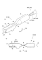
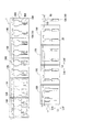
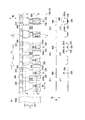
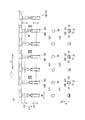
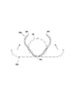
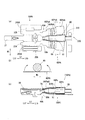
図1(a)は圧着端子10、及び電線先端部500Tの外観図であり、図1(b)は圧着端子10の幅方向の中間部分における縦断面図である。図2は圧着端子10の製造装置1の主要な構成のレイアウトを模式的に示した概念図である。図3(a)は端子連結帯300のキャリア長手方向Lcにおける上流側部分の平面図であり、図3(b1)、(b2)、(b3)は、図3(a)のA−A線断面における、それぞれ端子プレ加工部100、第1端子加工部110、第2端子加工部120に相当する部分の断面図を示す。図3(c1)、(c2)、(c3)は、図3(a)のB−B線断面における、それぞれ端子プレ加工部100、第1端子加工部110、第2端子加工部120に相当する部分の断面図を示す。図4(a)は端子連結帯300のキャリア長手方向Lcにおける中央部分の平面図であり、図4(b1)、(b2)、(b3)は、図4(a)のD−D線断面における、それぞれ第3端子加工部130、第4端子加工部140、第5端子加工部150に相当する部分の断面図を示す。図4(c1)、(c2)、(c3)は、図4(a)のE−E線断面における、それぞれ第3端子加工部130、第4端子加工部140、第5端子加工部150に相当する部分の断面図を示す。図5(a)は端子連結帯300のキャリア長手方向Lcにおける中央部分の平面図であり、図5(b1)、(b2)、(b3)は、図5(a)のG−G線断面における、それぞれ第6端子加工部160、第7端子加工部170、第8端子加工部180に相当する部分の断面図を示す。図5(c1)、(c2)、(c3)は、図5(a)のH−H線断面における、それぞれ第6端子加工部160、第7端子加工部170、第8端子加工部180に相当する部分の断面図を示す。
An embodiment of the present invention will be described in detail with reference to the drawings.
1A is an external view of the
本実施形態の圧着端子10の製造装置1は、平板状の端子基材300A(板条)を、図示しない送り機構により、上流側Lcuから間欠的に送りながら、図2、及び図3(a)に示すように、キャリア320と、該キャリア300の幅方向の少なくとも一端側から突出する端子金具10Aとで成る平板状の端子連結帯300として打ち抜くとともに、キャリア320の長手方向に沿って鎖状に備えた複数の端子金具10Aに対して曲げ加工など適宜の工程を間欠的に行い、端子形状に加工した端子金具10Aをキャリア320に対して切断することで上述した圧着端子10を製造する。
The
ここで、以下の説明において、キャリア320の長手方向をキャリア長手方向Lcに設定するとともに、キャリア320の幅方向をキャリア幅方向Wcに設定する。キャリア長手方向Lcにおける、キャリア320を送る方向(下流側)をキャリア長手方向下流側Lcdに設定するとともに、キャリア320を送る方向と反対方向(上流側)をキャリア長手方向上流側Lcuに設定する。
Here, in the following description, the longitudinal direction of the
さらに、圧着端子10(端子金具10A)の長手方向を端子軸方向Ltに設定するとともに、圧着端子10の幅方向を端子幅方向Wtに設定する。端子幅方向Wtは、キャリア長手方向Lcと一致する方向である。また、端子軸方向Ltにおける圧着部60に対するボックス部20の側を前方Ltf(先端側)とし、逆に、ボックス部20に対する圧着部60の側を後方Ltb(基端側)としている。
Furthermore, the longitudinal direction of the crimp terminal 10 (terminal fitting 10A) is set to the terminal axis direction Lt, and the width direction of the
さらにまた、圧着端子10(端子金具10A)の厚み方向Dにおいて、端子軸回りに曲げ加工する厚み方向の一方側を上方向Duに設定する。 Furthermore, in the thickness direction D of the crimp terminal 10 (terminal fitting 10A), one side of the thickness direction that is bent around the terminal axis is set to the upward direction Du.
まず、圧着端子10の製造方法により製造する圧着端子10の構成について図1(a),(b)、乃至図5を用いて説明する。
圧着端子10は、クローズドバレル型であるとともに、雌型の圧着端子形状に形成され、端子連結帯300におけるキャリア幅方向Wcの一端側から図2乃至図5に示す繋ぎ部310を介してキャリア幅方向Wcの外側へ向けて突出した端子金具10Aをキャリア320から分断して形成している。
First, the structure of the
The
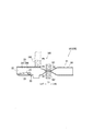
圧着端子10は、端子軸方向Ltの先端側である前方Ltfから後方Ltbに向かって、図示省略する雄型圧着端子10における挿入タブの挿入を許容するボックス部20と、ボックス部20の後方で、所定の長さのトランジション部40に形成された封止部50と、トランジション部40を介して端子軸方向において封止部50と連続して配置された圧着部60とで一体に構成している。
The
ボックス部20は、倒位の中空四角柱体で構成され、内部に、端子軸方向Ltの後方に向かって折り返され、挿入される雄型コネクタの挿入タブ(図示省略)に接触する弾性接触片21を備えている。
The
また、中空四角柱体であるボックス部20は、右側面部22と左側面部23、及び上面部24と底面部25とをそれぞれ対向させて、端子軸方向Ltへ細長い直方体形状に構成している。
Further, the
ボックス部20は、展開形状において、図3(a)に示すように、底面部25に対して端子幅方向Wtの一方側の外側に向けて、右側面部22と一方側上面部240とが連設されるとともに、端子幅方向Wtの他方側の外側に向けて、左側面部23と他方側上面部241とが連設されている。
一方側上面部240と他方側上面部241とは、ボックス部20を構成する各面部を周方向に折り曲げて直方体形状に構成した際に、互いに重合し、上面部24を構成する。
As shown in FIG. 3A, the
The one-side
封止部50は、トランジション部40における圧着部60側の部分を略平板状に押し潰すように変形させて、上下方向に対向する所定部分が互いに重合する偏平形状で構成している。
The sealing
圧着部60は、被覆電線500における少なくとも先端側の電線先端部500Tを挿入可能な円筒状に形成するとともに、周方向全体において連続する連続形状で一体に形成しているが、被覆電線500における少なくとも後述する導体先端部510Tを挿入可能な長さを備えていれば特にその長さは限定しない。
The
被覆電線500は、図1(a)に示すように、アルミニウムやアルミニウム合金などで形成するアルミニウム素線221を複数束ねた導体510を、絶縁樹脂で構成する絶縁被覆520で被覆して構成している。
前記電線先端部500Tは、図1(a)中に示すように、被覆電線500の先端側における、先端側の絶縁被覆520を剥離して導体510を露出させた導体先端部510Tと、被覆電線500の先端側における導体先端部510Tよりも後方であって絶縁被覆部分の先端側の被覆先端部520Tとで構成している
As shown in FIG. 1A, the covered
As shown in FIG. 1 (a), the
圧着部60には、周方向において対向端部60t同士が互いに対向する対向部分に、該対向端部60t同士を溶接する溶接部61を端子軸方向Ltに沿って形成している。
なお、圧着部60は、電線先端部500Tを挿入した状態でかしめて圧着することで、該電線先端部500Tと電気的に接続することができる。
In the crimping
In addition, the crimping | compression-
次に、上述した圧着端子10を製造する製造装置1、及び製造方法について図2乃至図15を用いて説明する。
なお、図6は第2端子加工工程の説明図であり、図7は高加工率加工工程を行った際の端子軸方向Ltの圧着箇所相当部60Aの形状の変化の様子を示す圧着箇所相当部60Aの直交断面図である。図8は第5端子加工工程の説明図であり、図9は第6端子加工工程において、整形工程を行った際の圧着箇所相当部60Aの形状の変化の様子を示す圧着箇所相当部60Aの直交断面図であり、図10は第6端子加工工程の説明図である。図11は第7端子加工工程170の説明図であり、図11(a1)は第7端子加工工程を行う前の端子金具10Aの外観図であり、図11(a2)は第7端子加工工程を行った後の端子金具10Aの外観図である。図11(b1)は端子金具10Aに第7端子加工工程を行う前の様子を示すトランジション相当部40Aの断面図であり、図11(b2)は端子金具10Aに第7端子加工工程を行っている最中の様子を示すトランジション相当部40Aの断面図である。
Next, a
FIG. 6 is an explanatory diagram of the second terminal processing step, and FIG. 7 corresponds to the crimping portion showing the change in the shape of the crimping
図12は、略円筒状の封止箇所相当部50Aを偏平形状に圧縮する様子を断面で示した第8端子加工部180の説明図であり、図12(a1)は封止箇所相当部50Aを後述する一対の封止部プレス型181,182でプレスする直前の様子を示し、図12(a2)は図12(a1)におけるX1部分の拡大図を示し、図12(b1)は封止箇所相当部50Aを一対の封止部プレス型181,182でプレスしている最中の様子を示し、図12(b2)は図12(b1)におけるX2部分の拡大図を示す。図13は、ボックス部押さえ治具183でボックス部20を押さえた様子を断面で示した第8端子加工部180の説明図であり、図14は第8端子加工工程においてファイバーレーザー溶接の様子を示す外観図である。図15(a)は、ファイバーレーザー溶接の様子を断面で示した説明図であり、図15(b)は、図15(a)中のX部拡大図である。
FIG. 12 is an explanatory view of the eighth
製造装置1は、図2乃至図5に示すように、平板状の端子基材300Aを、複数の段階に亘って、打ち抜きや、曲げ等の適宜の加工を段階的に行うユニットとして、キャリア長手方向Lcの上流側Lcuから下流側Lcdに沿って、1つの端子プレ加工部100と8つの端子加工部110〜180を直列に並列配置している。
As shown in FIGS. 2 to 5, the
端子プレ加工部100と端子加工部110〜180とは、図2に示すように、それぞれ、キャリア320の長手方向に沿って所定ピッチごとに等間隔に配設された複数の端子金具10Aのうち、2ピッチ分に相当する、隣り合う2つの端子金具10Aを1セットとして同時に加工可能に配置している。
As shown in FIG. 2, the
端子プレ加工部100において行う端子加工プレ加工工程では、図3(a),(b1),(c1)に示すように、端子基材300Aに対して打ち抜き、及び曲げ加工を行う。
詳しくは、端子プレ加工部100は、図示しないが、平板状の端子基材300Aを上流側から供給させながら、該端子基材300Aの通過部分をプレスにより帯状の端子連結帯300の形状に打ち抜く打ち抜き刃型を有した打ち抜きユニットと、ボックス部20における底面部25から端子軸方向の先端側へ舌片状に延設した弾性接触片21を曲げ加工する弾性接触片曲げ加工ユニットとで構成している。
In the terminal processing pre-processing step performed in the
Specifically, although not shown, the
ここで、平板状の端子金具10Aのうちボックス部20に相当する部分を、ボックス箇所相当部20Aに設定し、トランジション部40に相当する部分をトランジション相当部40Aに設定し、圧着部60に相当する部分を圧着箇所相当部60Aに設定する。さらに、ボックス部20における、底面部25、右側面部22、左側面部23、及び上面部24(一方側上面部240、及び他方側上面部241)のそれぞれを、底面相当部25A、右側面相当部22A、左側面相当部23A、上面相当部24A(一方側上面相当部240A、及び他方側上面相当部241A)に設定する。また、トランジション相当部40Aにおける封止部50に相当する部分を封止箇所相当部50に設定する。
Here, the portion corresponding to the
なお、端子プレ加工部100において、上述した打ち抜きユニットと弾性接触片曲げ加工ユニットとは別々に配置しても、キャリア長手方向Lcにおいて同じ箇所に配置してもいずれであってもよく、また、打ち抜きユニットと弾性接触片曲げ加工ユニットとをキャリア長手方向Lcにおいて別々に配置する場合は、その配列順位についても特に限定しない。
In the
8つの端子加工部110〜180は、主に、端子軸方向回りの曲げ加工を行う箇所であり、図2に示すように、端子プレ加工部100を通過した端子連結帯300の端子金具10Aに対して行う加工内容に応じて、第1端子加工部110、第2端子加工部120、第3端子加工部130、第4端子加工部140、第5端子加工部150、第6端子加工部160、第7端子加工部170、及び、第8端子加工部180で構成し、それぞれキャリア長手方向Lcの上流側から下流側に沿ってこの順に配置している。
また、これら第1端子加工部110から第8端子加工部180において行う加工を、それぞれ第1端子加工工程から第8端子加工工程に設定する。
The eight
Further, the processing performed in the first
端子製造方法は、主に、第1端子加工工程から第4端子加工工程によって、端子金具10Aの端子軸方向Ltにおける主に、ボックス箇所相当部20Aに対して端子軸方向Lt回りの曲げ加工を行うとともに、主に、第5端子加工工程と第6端子加工工程によって、端子金具10Aの端子軸方向Ltにおける主に、圧着箇所相当部60Aに対して加工を行い、第7端子加工工程と第8端子加工工程によって、封止箇所相当部50に対して加工を行う。
The terminal manufacturing method mainly performs bending processing around the terminal axis direction Lt with respect to the box portion
第1端子加工工程では、第1端子加工部110において、図3(c2)に示すように、平板状のボックス箇所相当部20Aの幅方向の両側を立ち上げる。具体的には、ボックス箇所相当部20Aにおける、右側面相当部22Aに対して幅方向の外側で連接している一方側上面相当部240Aと、左側面相当部23Aに対して幅方向の外側で連接している他方側上面相当部241Aを底面相当部25Aに対して絶対値が略60度程度の角度だけ端子軸回りに立ち上げる曲げ加工を行う。
In the first terminal processing step, in the first
第2端子加工工程では、図3(c3)に示すように、第2端子加工部120において、ボックス箇所相当部20Aにおける、右側面相当部22Aと右側面相当部23Aとを底面相当部25Aに対して端子軸回りに立ち上げる曲げ加工を行う。それと同時に、図3(b3)に示すように、トランジション相当部40Aの幅方向の両端部、及び、圧着箇所相当部60Aの幅方向の両端部を、弧状になるように滑らかに立ち上げる立ち上げ加工を行う。
詳しくは、第2端子加工部120では、図6に示すように、押上げ型122と押上受け型123とで構成したトランジション押上げ治具121を備えている。
トランジション相当部40Aに対して上下各側に、図6(a)に示すように、押上受け型123と押上げ型122とを対向配置する。押上受け型123をトランジション相当部40Aの上面に配置した状態で、押上げ型122をトランジション相当部40Aに向けて押圧することで、図6(b)に示すように、トランジション相当部40Aの底面全体を、圧着箇所相当部60Aに対して底上げする底上げ加工を行う。
なお、図6(b)中の端子金具Aの縦断面図は、図3(a)中のC−C線断面図を示している。
In the second terminal processing step, as shown in FIG. 3 (c3), in the second
Specifically, as shown in FIG. 6, the second
As shown in FIG. 6A, a push-up receiving die 123 and a push-up die 122 are arranged opposite to each other on the upper and lower sides with respect to the transition
In addition, the longitudinal cross-sectional view of the terminal metal fitting A in FIG.6 (b) has shown CC sectional view taken on the line in Fig.3 (a).
これにより、トランジション相当部40Aを上げ底とすることで、ボックス箇所相当部20Aにおける右側面相当部22Aと右側面相当部23Aとの立ち上げ形状変形に追従させることができ、トランジション相当部40Aが破断することを回避することができる。
Thereby, by setting the transition
第3端子加工工程では、第3端子加工部130において、図4(c1)に示すように、ボックス箇所相当部20Aにおける、右側面相当部22Aと右側面相当部23Aとを底面相当部25Aに対してそれぞれ絶対値が60度程度の立ち上がり角度となるまで曲げ加工する。
In the third terminal processing step, in the third
これにより、一方側上面相当部240A、及び右側面相当部22Aと、他方側上面相当部241A、及び右側面相当部23Aとは底面相当部25Aの幅方向の両側で互いに左右対称形状で対向した姿勢で曲げ加工される。
なお、第3端子加工工程においては、図4(b1)に示すように、圧着箇所相当部60Aに対しては、何も加工を施さない。
Thereby, the one side upper surface
In the third terminal processing step, as shown in FIG. 4 (b1), no processing is performed on the crimped
第4端子加工工程では、第4端子加工部140において、図4(c2)に示すように、ボックス箇所相当部20Aにおける底面相当部25Aの各側で立ち上がる一対の上面相当部240A,241Aのうち、一方側上面相当部240Aに対して他方側上面相当部241Aが倒伏した状態となるように、図示しない押圧治具により他方側上面相当部241Aを上方から押圧する。
なお、第4端子加工部140においては、図4(b2)に示すように、圧着箇所相当部60Aに対しては何も加工を施さない。
In the fourth terminal processing step, in the fourth
In the fourth
第5端子加工工程では、第5端子加工部150において、図4(c3)に示すように、他方側上面部241に対して一方側上面部240が重合するように、曲げ加工する。これにより、ボックス箇所相当部20Aを端子軸方向Ltへ長い直方体形状のボックス部20として形成することができる。
In the fifth terminal processing step, the fifth
さらに、第5端子加工工程においては、上述したボックス箇所相当部20Aの曲げ加工工程とともに、図4(a),(b3)に示すように、圧着箇所相当部60Aに対して高曲げ率加工工程を行う。
高曲げ率加工工程は、圧着箇所相当部60Aを未加工形状から筒状に曲げ加工するに伴って、圧着箇所相当部60Aにおける、所定の曲げ加工形状に塑性変形させる変形箇所の少なくとも一部を、当該塑性変形させる曲げ率よりも高い曲げ率で曲げ加工する工程である。
Further, in the fifth terminal processing step, as shown in FIGS. 4 (a) and 4 (b3), a high bending rate processing step is performed on the crimping
In the high bending rate processing step, at least a part of the deformed portion that is plastically deformed into a predetermined bent shape in the crimping
詳しくは、圧着箇所相当部60Aを、図7中の一点鎖線で示したように、平板形状に形成するとともに、幅方向の両端部分を端子軸回りに孤状に変形させた形状である未加工形状から第5端子加工部工程以降の工程によって、最終的に、図7の二点鎖線で示したような円筒状に曲げ加工する。
Specifically, as shown by the one-dot chain line in FIG. 7, the crimping portion
圧着箇所相当部60Aを、圧着箇所相当部60Aにおける幅方向の全体を円弧状に塑性変形させて最終的に円筒状へ曲げ加工する前に、第5端子加工部工程における高曲げ率加工工程において、圧着箇所相当部60Aの幅方向(周方向)の中間部分を、圧着箇所相当部60Aを未加工形状から円筒状に塑性変形させる曲率よりも高い曲率で曲げ加工した高曲げ率曲げ部60zを有するように、図7中の実線で示したような略Vの字形状に形成する。
In the high bending rate machining step in the fifth terminal machining portion step, the crimping portion
具体的には、高曲げ率加工工程は、図8に示すような高曲げ率加工治具151を用いて行う。
高曲げ率加工治具151は、凸状押圧治具152と凹型153とで構成する。
凸状押圧治具152は、圧着箇所相当部60Aを上述した未加工形状から円筒状に塑性変形させる曲率よりも高い曲率で径外方向に突出した凸部152aを周方向の一部に有する棒状に形成するとともに、凹型153は、凸状押圧治具152の凸部152aの凸形状に対応する凹形状に形成している。
Specifically, the high bending rate processing step is performed using a high bending
The high bending
The convex
凸状押圧治具152と凹型153とは、図8(a)に示すように、圧着箇所相当部60Aを隔てて上下各側に配置し、凸状押圧治具152の周方向における凸部152aを圧着箇所相当部60Aの幅方向の中間部分に対して上方から対向した状態で圧着箇所相当部60Aを下側に押圧することで、図8(b)に示すように、凸状押圧治具152と凹型153とで圧着箇所相当部60Aを直交断面視略Vの字状に塑性変形させることができる。
これにより、圧着箇所相当部60Aの幅方向の中間部分には、圧着箇所相当部60Aを円筒状に塑性変形させたときの曲率よりも高い曲率で曲げ加工した高曲げ率曲げ部60zを形成することができる。
As shown in FIG. 8A, the convex
Accordingly, a high bending
続く第6端子加工工程では、第6端子加工部160において、高曲げ率加工工程によって直交断面を略Vの字形状に曲げ加工した圧着箇所相当部60Aを、図5(b1)、及び図9に示すように円筒状の圧着部60へ整形させる整形工程を行う。
In the subsequent sixth terminal processing step, the crimped portion
整形工程では、図10に示すような整形治具161を用いて行う。整形治具161は、一対の外周整形用押圧型162,163で構成している。
一対の外周整形用押圧型162,163は、それぞれ圧着箇所相当部60Aに対して上下各側に配置され、それぞれ円筒状の圧着部60の外周面と同じ曲率を有する断面半円形に形成した凹部162a,163aを備えるとともに、それぞれの凹部162a,163aが互いに対向した状態で近接、又は離間可能に移動する。
In the shaping process, a shaping
The pair of outer periphery shaping pressing dies 162, 163 are respectively disposed on the upper and lower sides with respect to the crimping
整形工程では、図10(a)に示すように、一対の外周整形用押圧型162,163を、圧着箇所相当部60Aに対して上下各側に凹部162a,163aが互いに対向した状態で配置し、この状態で図10(b)に示すように、一方の外周整形用押圧型162と外周他方の外周整形用押圧型163とで、直交断面が略Vの字形状の圧着箇所相当部60Aをプレス加工する。
In the shaping step, as shown in FIG. 10 (a), a pair of outer periphery shaping press dies 162, 163 are arranged with the
このとき、圧着箇所相当部60Aの周方向における特に、図9中のドットを付した部分が径外方向へ曲げられることで、最終的に、圧着箇所相当部60Aを圧着部60として、所定の曲率を有する円筒状に整形することができ、幅方向の両端部が周方向において互いに突き合わさった状態の円筒状の圧着部60を形成することができる(図9参照)。
なお、一対の外周整形用押圧型162,163の間には、これら一対の外周整形用押圧型162,163により圧着箇所相当部60Aをプレス加工する際に、圧着箇所相当部60Aを円筒状にガイド可能な図示しない円柱状の芯棒を備えてもよい。
At this time, in particular in the circumferential direction of the crimping
In addition, between the pair of outer periphery shaping press dies 162, 163, when the crimping portion
また、封止箇所相当部50Aは、図5(b2)、及び図11(a1)に示すように、上述した第6端子加工工程において、圧着部60を円筒状に形成するに伴って、直交断面視略Uの字形状となるまで曲げ加工される。
Further, as shown in FIGS. 5 (b2) and 11 (a1), the sealing portion
続く第7端子加工工程は、第8端子加工部180において封止部形成工程を行う際のプレ工程として、封止箇所相当部50Aを、図11(a1)に示す状態から対向端部60t同士が近接するように絞って図11(a2)に示すような略円筒状に整形する。
In the subsequent seventh terminal processing step, as a pre-step when performing the sealing portion forming step in the eighth
具体的には、第7端子加工部170には、図11(b1)、(b2)に示すように、封止箇所相当部50Aを略円筒状に絞る封止部絞り治具171を備え、該封止部整形治具171は、上下各側の一対から成る外周整形型172,173と、内周整形芯棒174とで構成している。
Specifically, as shown in FIGS. 11B1 and 11B2, the seventh
図11(b1)に示すように、内周整形芯棒174を周方向の上端に隙間を有する円弧状の封止箇所相当部50Aに挿入した状態で、図11(b2)に示すように、上下各側に配置した一対の外周整形型172,173で押圧することで、封止箇所相当部50Aを略円筒状に絞ることができる。
As shown in FIG. 11 (b1), as shown in FIG. 11 (b2), the inner peripheral
第8端子加工工程では、第8端子加工部180において、略円筒状の封止箇所相当部50Aを偏平形状に圧縮して封止部50を形成する。
詳しくは、図12(a1)、及び図13に示すように、第8端子加工部180には、封止箇所相当部50Aを圧縮する一対の封止部プレス型181,182と、ボックス部20を押さえるボックス部押さえ治具183とを備えている。
In the eighth terminal processing step, in the eighth
Specifically, as shown in FIGS. 12A1 and 13, the eighth
一対の封止部プレス型181,182には、それぞれ封止箇所相当部50Aに対して対向させる対向面に、封止部50に相当する幅を有する圧着面181A,182Aを形成している。
In the pair of sealing portion press dies 181 and 182, pressure-bonding
一対の封止部プレス型181,182のうち、封止箇所相当部50Aに対して上側に配置する上側封止部プレス型181には、図12(a2)に示すように、圧着面181Aの幅方向の中間部分、すなわち、封止箇所相当部50Aの周方向の対向端部50t同士が突き合わせた状態で対向する対向部分に相当する部分に、凸部181aが形成されている。凸部181aは、先端部分を緩やかな円弧状に形成しているとともに、封止箇所相当部50Aの板厚の略半分程度の突出し長さで下方に突き出して形成している。
Of the pair of sealing portion press dies 181 and 182, the upper sealing portion press die 181 disposed on the upper side with respect to the sealing portion
また、前記ボックス部押さえ治具183は、図13中の仮想線で示したように、ボックス部20の上面部24に対して上方に退避した退避位置P1と、図13中の実線で示したように、ボックス部20の上面部24を押さえる押さえ位置P2との間で昇降自在に構成している。
Further, as shown by the phantom line in FIG. 13, the box
第8端子加工工程における封止部形成工程では、まず、ボックス部押さえ治具183を退避位置P1から押さえ位置P2まで降下させ、該ボックス部押さえ治具183によりボックス部20の上面に軽く当接した状態で該ボックス部20を押さえる。
In the sealing portion forming step in the eighth terminal processing step, first, the box
このように、ボックス部押さえ治具183によりボックス部20を押さえるとともに、上述した構成の一対の封止部プレス型181,182のそれぞれを、封止箇所相当部50Aに対して上下各側に配置した状態で、図12(b1)、及び図13に示すように、下側の封止部プレス型182に対して上側の封止部プレス型181を降下させて略円筒状の封止箇所相当部50Aをプレスすることで該封止箇所相当部50Aは、周方向における上側部分と下側部分とが対向する所定部分が互いに重合する偏平形状に圧縮し、封止部50として形成することができる。
As described above, the
なお、封止部50における、上下各側で互いに重合する重合部分のうち、上側に位置する部分を上側重合部分50uに設定するとともに、下側に位置する部分を下側重合部分50dに設定する(図12(b1)参照)。
Of the overlapping portions that overlap each other on the upper and lower sides of the sealing
このとき、特に、封止部50における対向端部50t同士が突き合わさる対向部分に着目すると、一対の封止部プレス型181,182による封止箇所相当部50Aのプレスに伴って、上側に配置する封止部プレス型181の凸部181aにより、上側重合部分50uの幅方向における対向部分を、図12(b2)に示すように、他の部分と比較して下側重合部分50dへしっかりと押し付けることができる。
At this time, when focusing attention on the facing portion where the facing
これにより、一対の封止部プレス型181,182によるプレスから封止部50を開放した状態において、封止部50の上側重合部分50uの幅方向における一方側と他方側とが下側重合部分50dに対して観音開きするように上方に復元変形することなく、上側重合部分50uと下側重合部分50dとをしっかりと重合した状態に保つことができる。
Thus, in a state where the sealing
また、上述した第8端子加工工程では、トランジション相当部40Aに上述した封止部50を形成することに加えてさらに溶接工程を行う。
溶接工程では、図14、及び図15(a),(b)に示すように、圧着部60の対向端部60t同士を突き合わせた状態で、第8端子加工部180に備えたファイバーレーザー溶接装置Fwを例えば、圧着部60の先端部60P1(ボックス部20側)から基端部60P2(キャリア320側)へ端子長手方向Ltに沿ってスライドさせながら一対の対向端部60t同士を溶接することで溶接部61を形成する。
Moreover, in the 8th terminal processing process mentioned above, in addition to forming the sealing
In the welding process, as shown in FIG. 14 and FIGS. 15A and 15B, a fiber laser welding apparatus provided in the eighth
上述した工程を経て端子形状に形成した端子金具10Aは、図示しないが端子連結帯300における繋ぎ部310においてキャリア320に対して切断することができ、圧着端子10として製造することができる。
Although not shown, the terminal fitting 10A formed in the terminal shape through the above-described steps can be cut with respect to the
上述した製造装置1、及び製造方法が奏する作用効果について説明する。
上述した構成によれば、上述したように、圧着箇所相当部60Aを略平板状の未加工形状から直接、円筒状に曲げ加工するのではなく、第5端子加工工程において、図7に示すように、圧着箇所相当部60Aにおける円筒状に変形する変形箇所の一部である幅方向の中間部分に、高曲げ率曲げ部60zを形成する。すなわち、当該中間部分に対して、未加工形状から、円筒状に対応する曲率を有する円弧形状に塑性変形させる曲げ率よりも高い曲げ率で曲げ加工する高曲げ率加工工程を行う。
The effect which the
According to the configuration described above, as described above, the crimping portion
さらに、この状態で、圧着箇所相当部60Aに対して最終形状である円筒状になるように、図9に示すように、第6端子加工工程において整形工程を行うことで、圧着箇所相当部60Aを、周方向において対向する対向端部60t同士が互いに離間する方向の内部応力が残留していない状態で塑性変形させることができる。
Furthermore, in this state, as shown in FIG. 9, a shaping process is performed in the sixth terminal processing step so that the final shape is a cylindrical shape with respect to the crimping
詳しくは、一般に、圧着部60の対向端部60t同士の隙間が目安として0.5mm以下である必要がある。圧着部60の対向端部60t同士の隙間が0.5mmより大きくなる場合には、ファイバーレーザーにより圧着部60の対向端部60t同士が対向する対向部分を溶接することが困難となるためである。
特に、圧着部60の対向端部60t同士の隙間は0.03mm以下であることが好ましい。圧着部60の対向端部60t同士の隙間が0.03mm以下である場合には、圧着部60の対向部分に、電線先端部500Tの圧着に確実に耐え得る溶接部61を形成することができ、筒状の圧着部60の優れた信頼性を得ることができるためである。
Specifically, in general, the gap between the
In particular, the gap between the
一方、圧着箇所相当部60Aの従来の曲げ加工の様子をあらわす図23(a)に示すように、圧着箇所相当部60Aを略平板状の未加工形状から直接、円筒状に曲げ加工した場合には、図23中の矢印Fに示すように、圧着箇所相当部60Aに元の未加工形状に復元しようとする内部応力Fが残留するなどの要因により、円筒状に曲げ加工しても、周方向において対向する対向端部60t同士が、互いに離間しようとする外向きの力が発生することになる。
On the other hand, as shown in FIG. 23 (a) showing the conventional bending process of the crimping part
そうすると、図23(b)に示すように、圧着部60の対向部分において、対向端部60t同士の間に、例えば、0.5mmより大きな隙間が生じ、該対向部分に対して焦点を合わせた状態でファイバーレーザーを照射することが困難となるため、対向部分に溶接部61を確実に形成できないという課題が生じていた。
Then, as shown in FIG. 23B, a gap larger than, for example, 0.5 mm is generated between the
これに対して、本実施形態では、高曲げ率加工工程において、圧着箇所相当部60Aを、略平板状の未加工形状から最終の曲げ加工形状である円筒状に曲げ加工した場合の曲率よりも大きな曲率の高曲げ率曲げ部60zを有する略Vの字形状に曲げ加工する。
On the other hand, in the present embodiment, in the high bending rate processing step, the crimped portion
さらに、整形工程において、高曲げ率加工工程後の圧着箇所相当部60Aに対して、圧着部60の幅方向の両側の対向端部60t同士を周方向において互いに突き合わせるとともに、幅方向の中間部分に対して両側に有する図9中のドットを付した直線部分が円弧状になるように、該直線部分を径外方向に曲げることで圧着箇所相当部60Aを、略Vの字形状から円筒形状に整形することができる。
Furthermore, in the shaping step, the
ここで、圧着箇所相当部60Aにおける、図9中のドットを付した前記直線部分を、円筒状に整形する際には、特に、径外方向に円弧状になるように曲げられるため、圧着部60の周方向における円弧状に曲げた部分には、円筒状に整形後においては、該円弧状に曲げた部分には、径内方向へ戻ろうとする内部応力Fが作用する。
Here, when the straight portion with dots in FIG. 9 in the crimping
これにより、整形工程後の圧着部60には、内向きの力が発生し、対向端部60t同士が押し合うように突き合わせることができる。
As a result, an inward force is generated in the crimping
従って、上述したように、高曲げ率加工工程を行った後で整形工程を行った圧着部60は、対向端部60t同士の隙間を例えば、0.03mm以下という少なくとも0.5mm以下にすることができるため、図14、及び図15に示すように、対向部分にファイバーレーザーを照射する際に、その焦点を対向端部60t間に合わせた状態で確実に溶接することができる。
Therefore, as described above, the crimping
また、上述したように、前記圧着箇所相当部60Aの幅方向における、一方側部分と他方側部分とが同じ長さとなる中間部分に、高曲げ率曲げ部60zを形成することで、整形工程において、圧着箇所相当部60Aを、円筒状に整形させる際に、例えば、高曲げ率曲げ部60zに対して一方側と他方側とがそれぞれ異なる長さである場合と比較して、これら一方側部分と他方側部分とのそれぞれを同じ長さ、及び曲率の円弧状に整形できるため、円筒状に整形した際に、圧着部60の対向部分において、一対の対向端部60tがバランスよく互いに押し合うように、略同じ大きさの力が作用する内向きの力を発生させることができる。
Further, as described above, in the shaping step, the high bending
また、上述したように、第2端子加工工程では、トランジション相当部40Aの底面全体を、図6に示すように、圧着箇所相当部60Aに対して底上げする加工も行うことで、ボックス箇所相当部20Aを上述したように、端子軸方向Lt回りに曲げ加工するに伴って、ボックス箇所相当部20Aと圧着箇所相当部60Aとの境界部分に相当するトランジション相当部40Aに、応力が集中して破断することを防ぐことができる。
Further, as described above, in the second terminal processing step, the entire bottom surface of the transition
詳しくは、第2端子加工工程において図3(c2)から図3(c3)の形状になるように、ボックス箇所相当部20Aにおける右側面相当部22Aと右側面相当部23Aとの立ち上げの際に、ボックス箇所相当部20Aに大きな曲げ加工を伴う一方で、圧着箇所相当部60Aには、図3(b2)から図3(b3)に示すように、殆ど変形を強いられることがない。
Specifically, in the second terminal machining step, when the right side
このため、このような端子軸方向Ltの各側における曲げ加工による変形量の違いを伴う加工によって、これらボックス箇所相当部20Aと圧着箇所相当部60Aとの間に相当するトランジション相当部40Aにおいては、過大な応力が加わることになり、亀裂が生じるなどのおそれがあった。
For this reason, in the transition
これに対して、第2端子加工工程において、ボックス箇所相当部20Aに対して端子軸方向Lt回りの曲げ加工を行うに伴って、トランジション相当部40Aも同時に上げ底を行うことで、トランジション相当部40Aを、ボックス箇所相当部20Aにおける右側面相当部22Aと右側面相当部23Aとの立ち上げ形状変形に追従させるように変形させることができ、ボックス箇所相当部20Aと圧着箇所相当部60Aとの間の変形量の違いを緩和することができる。
On the other hand, in the second terminal processing step, the transition
従って、トランジション相当部40Aに過大な負荷が加わることで亀裂が生じることを防ぎつつ、ボックス箇所相当部20Aにおける右側面相当部22Aと右側面相当部23Aとを底面相当部25Aに対して略垂直に立ち上げることができるという所望の曲げ加工を行うことができる。
Accordingly, the right side surface
さらに、第2端子加工工程では、トランジション相当部40Aの底面全体を、圧着箇所相当部60Aに対して底上げする加工も行うことで、トランジション相当部40Aと圧着箇所相当部60Aとの境界部分を段状とすることができる(図6の下側の図参照)。
Furthermore, in the second terminal processing step, the entire bottom surface of the transition
このため、第2端子加工工程以降の工程において、ボックス箇所相当部20Aを変形させる際に、該ボックス箇所相当部20Aに加わった応力が圧着箇所相当部60Aにまで不測に伝わることを防ぐことができ、第2端子加工工程以後の工程においてボックス箇所相当部20Aと圧着箇所相当部60Aとのそれぞれを、所望の形状にスムーズに曲げ加工することができる。
For this reason, when deforming the box location
さらに、第8端子加工工程において、一対の封止部プレス型181,182により封止箇所相当部50Aのプレスする際には、図13を用いて説明したように、ボックス部押さえ治具183によってボックス部20を押さえることにより、いわゆるボックス部20の首折れを防ぐことができる。
Furthermore, in the eighth terminal processing step, when the sealed portion
詳述すると、一対の封止部プレス型181,182により、封止箇所相当部50Aをプレスする際に圧着端子10は衝撃を受けて浮き上がろうとする慣性力が作用する。その際、封止部50は一対の封止部プレス型181,182により位置が規制されている。
More specifically, when the sealing portion
このため、ボックス部押さえ治具183を備えていない従来の第8端子加工部の構成の場合、封止箇所相当部50Aをプレスする際の衝撃により、封止部50に対してボックス部20が浮き上がろうとして、ボックス部20が封止部50に対して不測に分断するといういわゆるボックス部20の首折れが生じるおそれがあった。
For this reason, in the case of the structure of the conventional 8th terminal processing part which is not provided with the box part holding | maintenance jig |
これに対して、本実施形態の第8端子加工工程では、図13に示すように、ボックス部押さえ治具183によりボックス部20を押さえ付けることができるため、一対の封止部プレス型181,182により封止箇所相当部50Aをプレスすることに伴って、該封止箇所相当部50Aが衝撃を受けても、ボックス部20に作用する慣性力をボックス部押さえ治具183によって、受け止めることができる。従って、いわゆるボックス部20の首折れを防ぐことができる。
In contrast, in the eighth terminal processing step of the present embodiment, as shown in FIG. 13, the
さらに、ボックス部押さえ治具183によりボックス部20を押さえ付けることにより、封止部50に対してボックス部20が不測に撓み変形することがないため、端子軸方向Ltについて直進精度に優れた圧着端子10を形成することができる。
Furthermore, since the
よって、被覆電線500における電線先端部500Tを圧着部60の内部に端子軸方向Ltに沿って適切に挿入することができる。
Therefore, the electric wire front-end |
なお、圧着端子10におけるボックス部押さえ治具183によりボックス部20を押さえ付ける箇所は、上面部24に限らず、他の箇所であってもよく、また、ボックス部20以外の箇所を押さえ付けてもよい。
In addition, the location where the
この発明の構成と、実施形態との対応において、
この発明の圧着端子は、実施形態の端子金具10A、又は圧着端子10に対応し、
以下同様に、
高エネルギー密度熱源発生溶接手段は、ファイバーレーザー溶接装置Fwに対応するも、この発明は、上述の実施形態の構成のみに限定されるものではなく、請求項に示される技術思想に基づいて応用することができ、多くの実施の形態を得ることができる。
また他の実施形態として、圧着箇所相当部60Aを円筒状の圧着部60として曲げ加工する際に、第5端子加工工程において上述した高曲げ率加工工程を行うとともに、第6端子加工工程において上述した整形工程を行うに限らない。
In the correspondence between the configuration of the present invention and the embodiment,
The crimp terminal of the present invention corresponds to the terminal fitting 10A of the embodiment or the
Similarly,
Although the high energy density heat source generating welding means corresponds to the fiber laser welding apparatus Fw, the present invention is not limited only to the configuration of the above-described embodiment, and is applied based on the technical idea shown in the claims. And many embodiments can be obtained.
As another embodiment, when the crimping portion
例えば、図3(b3)に示すような略平坦状の圧着箇所相当部60Aを、図16(a)に示すように、幅方向の両端部60tが互いに突き合わさるまで曲げ加工する高曲げ率加工工程と、幅方向の両端部60t同士が突き合わさった圧着箇所相当部60Aの突合せ部分60Tを上方から押し込む整形工程を行うことで、圧着箇所相当部60Aを円筒状の圧着部60に曲げ加工してもよい。
For example, a high-bending-rate machining is performed in which a substantially flat crimping portion
具体的には、高曲げ率加工工程において、幅方向の両端部60tが弧状に立ち上がった略平坦状の圧着箇所相当部60A(図3(b3)参照)を、幅方向の中間部分を中心に全周に亘って曲げ加工していき、最終的に圧着箇所相当部60Aの幅方向の両端部60tが互いに突き合わさるまで図16(a)に示すように、幅方向の中間部分に対して両側部分を徐々に円弧状に整形していく。
Specifically, in the high bending rate processing step, the substantially flat crimping portion
高曲げ率加工工程において、このように圧着箇所相当部60Aに対して高曲げ率加工工程を行うことにより、圧着箇所相当部60Aは、端子軸方向Ltに対する直交断面が略立位の楕円形状となり、圧着箇所相当部60Aの幅方向の中間部分には、幅方向の両端部60tが互いに突き合わさる程度の高い曲率を有する高曲げ率曲げ部60zが形成される。
In the high bending rate processing step, by performing the high bending rate processing step on the crimping portion
その後に行う整形工程において、圧着箇所相当部60Aにおける幅方向の両端部60t同士が突き合わさる突合せ部分60Tを、図16(b)に示すように、下方(径内方向)へ押し込むことにより(図16(b)中の矢印D参照)、圧着箇所相当部60Aを、円筒状に整形することができ、円筒状の圧着部60として曲げ加工することができる。
In the subsequent shaping step, as shown in FIG. 16B, the abutting
上述した他の実施形態における加工方法によれば、高曲げ率加工工程において、圧着箇所相当部60Aの幅方向の中間部分に形成した高曲げ率曲げ部60zは、略平坦状から幅方向の両端部60tが互いに突き合わさる程度まで十分に高い曲げ率とする。
According to the processing method in the other embodiments described above, in the high bending rate processing step, the high bending
これにより、円筒状の圧着部60の対向端部60t同士が離間しようとする内部応力が作用するスプリングバックの影響を確実に解消することができる。
すなわち、突合せ部分60Tを下方(径内方向)へ押し込むことにより、圧着部60の対向端部60tに、対向端部60t同士が押し合うような内部応力を作用させることができるため(図16(b)中の矢印F参照、その後に行う整形工程において、圧着箇所相当部60Aを円筒状に確実に整形することができる。
Thereby, the influence of the spring back which the internal stress which the opposing
That is, by pressing the
従って、圧着部60は、正確に円筒状に形成することができるとともに、周方向において対向する端部60t同士が積極的に互いに突き合わさった状態に保つことができる。
Therefore, the crimping
また他の実施形態として、高曲げ率加工工程において、上述した実施形態では、圧着箇所相当部60Aの幅方向の中間部分に高曲げ率曲げ部60zを形成したが、このように、圧着箇所相当部60Aの幅方向の一部に高曲げ率曲げ部60zを形成するに限らず、図17(a1)に示すように、圧着箇所相当部60PAの幅方向の全体を、絞るなどして最終的に円形状に曲げ加工する曲率、すなわち、図17(a2)に示した円筒状の圧着部60の曲率よりも高い曲率に曲げ加工してもよい。
As another embodiment, in the high bending rate processing step, in the above-described embodiment, the high bending
これにより、その後の整形加工において、圧着箇所相当部60PAを、図17(a2)に示すように、円形状に整形した際に、圧着部60における対向部分に内向きの力を発生させることができ、対向端部60t同士が押し合うように突き合わせることができる。
Thus, in the subsequent shaping process, when the crimping portion equivalent portion 60PA is shaped into a circular shape as shown in FIG. 17 (a2), an inward force is generated at the opposing portion of the crimping
また、圧着部60は、円筒状に曲げ加工するに限らず、圧着箇所相当部60Aの幅方向において複数箇所に亘って曲げ加工し、圧着箇所相当部60Aの直交断面が最終的に多角形状になるように曲げ加工してもよい。
例えば、圧着箇所相当部60PBの直交断面が最終的に四角形状になるように曲げ加工する場合には、図17(b1)に示すように、圧着箇所相当部60PBの幅方向における4か所の曲げ加工部のうち、例えば、所定の2箇所を、最終的に四角形状の圧着部60とする際の曲げ角度である直角よりも大きな角度となるように曲げ加工して、該所定の2箇所のそれぞれに高曲げ率曲げ部60zを形成する。
Further, the crimping
For example, when bending is performed so that the orthogonal cross section of the crimping portion corresponding portion 60PB finally becomes a quadrangle shape, as shown in FIG. 17 (b1), four locations in the width direction of the crimping portion corresponding portion 60PB are provided. Among the bent portions, for example, two predetermined portions are bent so as to have an angle larger than a right angle that is a bending angle when finally forming the quadrangular pressure-
そして、図17(b2)に示すように、高曲げ率加工工程の後の整形工程において、高曲げ率曲げ部60zを形成した所定の2箇所のそれぞれが直角になるように圧着箇所相当部60PBを整形してもよい。
Then, as shown in FIG. 17 (b2), in the shaping step after the high bending rate working step, the crimping portion equivalent portion 60PB so that each of the two predetermined portions where the high bending
これにより、圧着箇所相当部60PBを、図17(b2)に示すように、四角形状に整形した際に、圧着部60Bにおける対向部分に内向きの力が発生し、対向端部60t同士が互いに押し合うように突き合わせることができる。
As a result, when the crimping portion corresponding portion 60PB is shaped into a quadrangular shape as shown in FIG. 17 (b2), an inward force is generated at the opposing portion of the crimping
従って、図17(a2)、及び図17(b2)のいずれの圧着部60,60Bにおいても、対向端部60t同士が対向する対向部分に隙間が生じることがないため、該対向部分を確実に溶接することができる。
Accordingly, in any of the crimping
また、他の実施形態として、上述した実施形態における製造装置1では、端子プレ加工部100と端子加工部110〜180とのそれぞれをキャリア長手方向Lcに沿って2つ一組で配置したが(図2参照)、この構成に限定せず、端子プレ加工部100と端子加工部110〜180とのそれぞれを、キャリア長手方向Lcに沿って上流側Lcuから下流側Lcdへ間欠的に送られる端子金具10Aに対して1ピッチずつ加工を行うことが可能に、キャリア長手方向Lcに沿って1つずつ配置してもよい。
または、製造装置1では、端子プレ加工部100と端子加工部110〜180とのそれぞれを、キャリア長手方向Lcに沿って、2つ一組、或いは一つずつ配置するに限らず、その他の配置数で配置してもよく、また、端子加工部ごとに異なる配置数で配置してもよい。
In addition, as another embodiment, in the
Alternatively, in the
他の実施形態として、整形工程において、圧着箇所相当部60Aの円筒形状への整形に用いた整形治具161は、上述したように、一対の外周整形用押圧型162,163のみで構成するに限らず、外周整形用押圧型162,163の他に、圧着箇所相当部60Aを円筒状に整形する際に、該圧着箇所相当部60Aの内周面を整形する内周整形用芯棒を備えて構成してもよい。
As another embodiment, in the shaping step, the shaping
内周整形用芯棒は、図示しないが、円筒状の圧着部60の内周面の曲率と略同じ曲率の外周面を有する円柱状に構成することができる。
Although not shown, the inner peripheral shaping core rod can be formed in a columnar shape having an outer peripheral surface having substantially the same curvature as the curvature of the inner peripheral surface of the
内周整形用芯棒を備えた整形治具161を用いて整形工程を行う場合には、図示しないが、内周整形用芯棒を、断面略Vの字形状の圧着箇所相当部60Aの内側空間に挿入した状態で配置し、この状態で一方の外周整形用押圧型162,163と他方の外周整形用押圧型162,163とで、直交断面が略Vの字形状の圧着箇所相当部60Aをプレス加工することで、内周整形用芯棒の外周面に沿った滑らかな円周形状の内周面を有した円筒状の圧着部60を形成することができる。
When the shaping step is performed using the shaping
また、他の実施形態として、第7端子加工部170には、上述したように、封止部絞り治具171として、一対の外周整形型172,173と、内周整形芯棒174とを備えて構成したが(図11(b1)、(b2)参照)、封止部絞り治具171は、この構成に限定せず、他の構成であってもよい。
As another embodiment, as described above, the seventh
例えば、内部に内周整形芯棒174を挿入しない状態の封止箇所相当部50Aに対して上下各側に配置した一対の外周整形型172,173によって、該封止箇所相当部50Aを押圧しても、略円筒状に絞ることができるのであれば、封止部絞り治具171には、内周整形芯棒174を備えずに、一対の外周整形型172,173のみで構成してもよい。
For example, the sealing
また、他の実施形態として、圧着部60の一対の対向端部60t,60tに溶接部61を形成する溶接工程は、複数の端子加工工程の中でも最終の工程である第8端子加工工程で行ったが、これに限らず、第6端子加工工程において圧着箇所相当部60Aを円筒状に整形する工程以降の工程であれば、いずれの工程において溶接工程を行ってもよい。
As another embodiment, the welding process for forming the welded
また、圧着端子10は、本実施形態では、上述したように、ボックス部20と圧着部60とを備えた雌型圧着端子で構成したが、この構成に限定せず、少なくとも圧着部60を有する構成であれば、他の雌型圧着端子のボックス部20に挿入接続する挿入タブをボックス部20の代わりに備えた雄型圧着端子として構成しても、或いは、圧着部60のみで構成し、複数本の被覆電線500の例えば、アルミニウム芯線などの導体510を束ねて接続するための圧着端子として構成してもよい。
Further, in the present embodiment, the
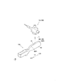
また、他の実施形態として、圧着端子10Pは、図18(a)、(b)に示すように、ボックス部20におけるトランジション部40(封止部50)との連設部分における、端子幅方向Wtの両側の側壁に、基端側から切欠いた切欠き部70を形成してもよい。
As another embodiment, the
このような切欠き部70は、後述する展開形状の圧着端子に基づいて説明すると、図19に示すように、ボックス箇所相当部20Aの右側面部22Aと左側面部23Aとにおけるトランジション相当部40Aとの連接部分に、端子幅方向Wtの外側端部を切欠いて形成している。
Such a
このように、ボックス箇所相当部20Aにおけるトランジション相当部40Aとの連設部分に切欠き部70を形成することにより、圧着端子10Pの全長を所定の端子サイズの規格を満たす端子長に保ちつつ、所望の端子形状に確実に曲げ加工することができる。
In this way, by forming the
詳しくは、圧着端子10Pを図19に示すような展開形状から図18(b)に示すような立体形状に曲げ加工する際には、図3(c2)、(c3)、及び図4(c1)、(c2)に示すように、ボックス箇所相当部20Aの曲げ加工を先行して行い、ボックス箇所相当部20Aの曲げ加工が略完成した段階で、図4(b3)、及び図5(b1)、(b2)、(b3)に示すように圧着箇所相当部60Aの曲げ加工を主体的に行う。
Specifically, when the crimping terminal 10P is bent from the developed shape as shown in FIG. 19 to the three-dimensional shape as shown in FIG. 18B, FIGS. 3C2 and 3C3 and FIG. ), (C2), the box portion
このため、各工程ごとにおけるボックス箇所相当部20Aと圧着箇所相当部60Aとのそれぞれの曲げ加工に伴う変形量の違いにより、ボックス箇所相当部20Aと圧着箇所相当部60Aとの間に相当するトランジション相当部40Aにおいては、過大な応力が加わることになる。中でも特に、ボックス箇所相当部20Aとトランジション相当部40Aとの境界部分において急激な曲げ変形が強いられるため、該境界部分に応力が集中し、亀裂が生じるなどのおそれがあった。
For this reason, the transition corresponding to between the box part
一方、ボックス箇所相当部20Aとトランジション相当部40Aとの境界部分において急激な曲げ変形に伴い集中的に加わる応力を分散するための対策として、トランジション相当部40Aを長く形成することが考えられる。
On the other hand, it is conceivable that the transition
しかし、トランジション相当部40Aを長く形成した場合、それに伴って圧着端子10Pの全長も長くなる。そうすると圧着端子10Pが所定の規格を満たさない端子長となり、例えば、図示しないがコネクタの端子挿通孔に適切に挿入不能となるという別の課題が生じることになる。
However, when the transition
これに対して、本実施形態の圧着端子10Pにおいては、ボックス箇所相当部20Aにおけるトランジション相当部40Aとの連設部分に切欠き部70を形成することで、ボックス箇所相当部20Aを曲げ加工する過程において境界部分に変形量の違いに伴い作用する過大な応力を切欠き部70を有した連設部分にも分散させることができる。
On the other hand, in the
よって、ボックス箇所相当部20Aを曲げ加工する過程において境界部分に応力が集中することを防ぎ、所望の端子形状に確実に曲げ加工することができる。
Therefore, it is possible to prevent stress from concentrating on the boundary portion in the process of bending the box
しかも、本実施形態の圧着端子10Pにおいては、ボックス箇所相当部20Aにおけるトランジション相当部40Aとの連設部分に切欠き部70を形成したため、トランジション相当部40A自体を長尺に形成せずともボックス箇所相当部20Aの曲げ加工を行う際に、トランジション相当部40Aに加わる応力集中を緩和することができる。
In addition, in the
従って、圧着端子10Pの全長を所定の規格を満たす端子長に保つことができるため、コネクタの端子挿通孔に適切に挿入することができるなど、圧着端子10Pの全長を所定の規格を満たす端子長に保つことができる。
Accordingly, since the entire length of the
また、他の実施形態として、圧着端子10Pは、圧着部60Pを端子軸方向Ltに沿って同径となる寸胴に形成するに限らず、図20に示すように、端子軸方向Ltにおいて径が異なるように段状に形成してもよい。
Further, as another embodiment, the
なお、図20は、他の実施形態における圧着端子10Pの斜視図を示している。
FIG. 20 is a perspective view of a
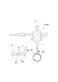
詳しくは、圧着部60Pは、先端側開口閉塞部60Paと、導体圧着部60Pbと、段差部60Pcと、被覆圧着部60Pdとで一体に構成している。
導体圧着部60Pbは、電線先端部500Tを挿入した状態において、端子軸方向Ltにおいて、挿入した導体先端部510Tに相当する箇所であり、導体先端部510Tの外径に対して略同等、或いは僅かに大きな内径を有して被覆圧着部60Pdの外径よりも小径に形成している。
Specifically, the crimping
The conductor crimping portion 60Pb is a portion corresponding to the inserted
被覆圧着部60Pdは、電線先端部500Tを挿入した状態において、端子軸方向Ltにおいて、挿入した被覆先端部520Tに相当する箇所であり、被覆先端部520Tの外径に対して略同等、或いは僅かに大きな内径を有して形成している。
The coated crimping portion 60Pd is a portion corresponding to the inserted coated
圧着部60Pにおける導体圧着部60Pbと被覆圧着部60Pdとの間の段差部60Pcは、端子軸方向Ltに直交するような段差形状ではなく、被覆圧着部60Pdから導体圧着部60Pbにかけて滑らに縮径するような段差形状に形成している。
The stepped portion 60Pc between the conductor crimped portion 60Pb and the coated crimped portion 60Pd in the crimped
先端側開口閉塞部60Paは筒状の圧着部60Pの端子軸方向Ltにおける先端側が開口しないように閉塞している箇所である。
The distal end side opening closing portion 60Pa is a portion where the distal end side in the terminal axial direction Lt of the cylindrical crimping
上述した圧着端子10Pは、図19に示すような端子金具10PAに対して段付き芯棒80を用いて図21(a)、(b)、(c)に示すように製造する。
なお、図21(a)は、端子金具10PAの平面図であり、端子金具10PAにおける圧着箇所相当部60PAに芯棒600を配置した状態の平面図を示し、図21(b)は、図21(a)中のI−I矢視断面図を示し、図21(c)は、圧着箇所相当部60PAを円筒状に形成した状態の縦断面図を示している。
The
FIG. 21A is a plan view of the terminal fitting 10PA, showing a plan view in a state where the core rod 600 is disposed in the crimping portion equivalent portion 60PA of the terminal fitting 10PA, and FIG. 11A is a cross-sectional view taken along the arrow I-I in FIG. 21A, and FIG. 21C is a vertical cross-sectional view in a state where the crimping portion corresponding portion 60PA is formed in a cylindrical shape.
具体的には、端子金具10PAは、図19、及び21(a)に示すように、端子軸方向Ltの先端側Ltfから基端側Ltbに沿ってボックス箇所相当部20A、トランジション相当部40A、圧着箇所相当部60PAをこの順に配設している。
Specifically, as shown in FIGS. 19 and 21 (a), the terminal fitting 10PA includes a box location
トランジション相当部40Aの端子軸方向Ltにおける後側部分には、封止部相当箇所50Aを配設している。また、圧着箇所相当部60PAは、端子軸方向Ltの先端側Ltfから基端側Ltbに沿って加工前の先端側開口閉塞部60Paに相当する先端側開口閉塞相当部60PaA、加工前の導体圧着部60Pbに相当する導体圧着箇所相当部60PbA、加工前の段差部60Pcに相当する段差部分相当箇所60PcA、加工前の被覆圧着部60Pdに相当する被覆圧着箇所相当部60PdAをこの順に配設している。
A sealing portion
図19に示すように、先端側開口閉塞相当部60PaAは、圧着箇所相当部60PAと封止部相当箇所50Aとを連設可能に端子軸方向Ltの基端側Ltbから先端側Ltfに沿って徐々に幅小に形成している。
段差部分相当箇所60PcAは、段差部60Pcに相当し、導体圧着箇所相当部60PbAと被覆圧着箇所相当部60PdAとのそれぞれの幅に応じて端子軸方向Ltの基端側Ltbから先端側Ltfに沿って徐々に幅小になるように、幅方向の外側縁部を端子軸方向Ltに対して傾斜させて形成している。
As shown in FIG. 19, the distal end side opening blocking equivalent portion 60PaA extends from the proximal end side Ltb in the terminal axial direction Lt along the distal end side Ltf so that the crimping portion equivalent portion 60PA and the sealing portion
The step portion equivalent portion 60PcA corresponds to the step portion 60Pc, and extends from the base end side Ltb in the terminal axial direction Lt to the tip end side Ltf in accordance with the widths of the conductor crimping portion equivalent portion 60PbA and the coated crimping portion equivalent portion 60PdA. The outer edge in the width direction is inclined with respect to the terminal axis direction Lt so that the width gradually decreases.
さらに、被覆圧着箇所相当部60PdA、及び導体圧着箇所相当部60PbAについても、端子軸方向Ltの基端側Ltbから先端側Ltfに沿って徐々に幅小になるように、それぞれの幅方向の外側縁部を端子軸方向Ltに対して傾斜させて形成している。 Further, the outer side in the width direction of the covering crimping part corresponding part 60PdA and the conductor crimping part corresponding part 60PbA is gradually reduced from the base end side Ltb in the terminal axial direction Lt along the distal end side Ltf. The edge is formed to be inclined with respect to the terminal axis direction Lt.
加えて、圧着箇所相当部60PAの基端側端部については、端子幅方向Wtにおける中間部分に有する繋ぎ部310に対して端子幅方向Wtの外側部分が、キャリア320との端子軸方向Ltの間隔が徐々に広がるように端子幅方向Wtに対して傾斜させて形成している。
In addition, with respect to the base end side end of the crimping portion corresponding portion 60PA, the outer portion in the terminal width direction Wt is in the terminal axial direction Lt with the
一方、封止部相当箇所50Aの端子幅方向Wtの両側の外側端部は、端子軸方向Ltに対して傾斜せずに平行に形成している。
On the other hand, the outer end portions on both sides in the terminal width direction Wt of the sealing portion
また、導体圧着箇所相当部60PbAには、セレーション68(係合溝)を形成している。セレーション68は、導体圧着箇所相当部60PbAの端子幅方向Wt全長に亘って形成するとともに、端子幅方向Wtの外側に対して中央部分が徐々に端子幅方向Wtの基端側へ湾曲した平面視弓状に形成している。
Further, serrations 68 (engagement grooves) are formed in the conductor crimping portion corresponding portion 60PbA. The
上述した圧着端子10Pは、第5端子加工工程から第6端子加工工程にかけて、上述した端子金具10PAに対して段付き芯棒80を用いて曲げ加工して製造することができる。
The above-described
具体的には、図21に示すように、段付き芯棒80を端子金具10PAにおける封止箇所相当部50A、及び圧着箇所相当部60PAの端子幅方向Wtの中間部分において端子軸方向Ltに沿って封止部相当箇所50Aから圧着箇所相当部60PAにかけて配置する。
Specifically, as shown in FIG. 21, the stepped
このとき、段付き芯棒80の段差部分81と圧着箇所相当部60PAにおける段差部分相当箇所60PcAとを端子軸方向Ltにおいて位置決めした状態に配置する。
At this time, the stepped
この状態で適宜、図示しない押圧型により外側から押圧するなどして、封止部相当箇所50A、及び圧着箇所相当部60PAによって段付き芯棒80を囲繞するように封止箇所相当部50A、及び圧着箇所相当部60PAにかけての部分を段付き芯棒80の外周面に沿って円筒状に曲げ加工する。
In this state, by appropriately pressing from the outside with a pressing mold (not shown), the sealing portion
このとき、特に図21(a)、(b)、(c)に示すように、封止箇所相当部50A、及び圧着箇所相当部60PAは、段付き芯棒80の段差部分81の外周面に弓状の段差部分相当箇所60PcAを当接させながら段付き芯棒80に囲繞する。
At this time, particularly as shown in FIGS. 21A, 21B, and 21C, the sealing portion
以上により、段差形状に形成した圧着部60Pを有する圧着端子10Pを形成することができる。
以下では、上述する段差形状に形成した圧着部60Pを有する圧着端子10Pの作用効果について、図22、及び図24を用いて説明する。
In this way, the
Below, the effect of the
なお、図22は、圧着部60Pを段差形状にした場合における圧着接続工程後の導体圧着部60Pbの断面図を示し、図24は、圧着部600を段差形状に形成していない場合における圧着接続工程後の従来の導体圧着部600Pdの断面図を示している。
22 shows a cross-sectional view of the conductor crimping portion 60Pb after the crimping connection step when the crimping
上述する段差形状に形成した圧着部60Pの場合、導体圧着部60Pbを、段差形状に形成していない従来の圧着部600Pにおける導体圧着部600Pdと比較して導体先端部510Tとの隙間が僅かになるため、導体先端部510Tと圧着接続する際の径方向内側への圧縮量を抑えることができ、余肉の発生を防止することができる。
In the case of the crimping
従って、導体圧着部60Pbを導体先端部510Tに対して密着させることができ、圧着部60P内部の止水性を向上させることができる。
Therefore, the conductor crimping portion 60Pb can be brought into close contact with the
詳述すると、段差形状に形成していない従来の圧着部600は、段差形状に形成した本実施形態の圧着部60Pに比べて、導体圧着部60Pbと導体先端部510Tとの隙間が大きいため、導体圧着部60Pbを導体先端部510Tに対して圧着接続する際に、径方向内側への変形量が大きくなる。
More specifically, the conventional crimping part 600 not formed in a step shape has a larger gap between the conductor crimping part 60Pb and the
そうすると、従来の導体圧着部600Pbは、導体先端部510Tに対して圧着接続した際に余肉が発生し、図24に示すように、該余肉が径方向内側に張り出すように倒れるいわゆる内倒れ部分600zが生じる。
As a result, the conventional conductor crimping portion 600Pb generates a surplus when crimped and connected to the
この圧着部60に内倒れ部分600zが生じた場合、電線先端部500Tと圧着接続する際に、内倒れ部分600zが障害となって、導体圧着部60Pbの内部空間の隅部まで導体先端部510Tが行き渡らず、図24中の一部拡大図のように、導体圧着部60Pbと導体先端部510Tとの間に隙間が発生するおそれがあった。
When an inwardly-turned
すなわち、段差形状に形成していない従来の圧着部600Pの場合、電線先端部500Tと圧着接続した際に、導体圧着部600Pbと導体先端部510Tとの密着性が低下し、毛細管現象により内部に水分が侵入するなどして所望の電気的特性を得られないという課題があった。
That is, in the case of the conventional crimping
これに対して、段付き形状に形成した本実施形態の圧着部60Pは、上述したように段付き形状に形成していない圧着部600Pに比べて、電線先端部500Tを挿入した状態において、導体圧着部60Pbと導体先端部510Tとの隙間を小さくすることができる。
On the other hand, the crimping
このため、圧着部600Pと電線先端部500Tとを圧着接続しても、導体圧着部60Pbに内倒れ部分600zが発生することなく、導体圧着部60Pbと導体先端部510Tとを密着した状態で圧着することができ、優れた電気的特性を得ることができる。
For this reason, even if the crimping
さらに、圧着部60Pにおける段差部60Pcを、被覆圧着部60Pdから導体圧着部60Pbにかけて滑らに縮径させた段差形状に形成したため、電線先端部500Tを圧着部60Pの内部へ挿入する際に、導体先端部510Tが段差部60Pcに引っ掛かかって導体先端部510Tを構成する素線がばらけるこがなく、電線先端部500Tを圧着部60Pの内部へ奥までスムーズに挿入することができる。
Further, since the stepped portion 60Pc in the crimping
封止箇所相当部50A、及び圧着箇所相当部60PAは、平面視弓状に形成した段差部分相当箇所60PcAを、段付き芯棒80の段差部分81の外周面に押し当てるようにして、端子軸方向Ltにおいて位置決めした状態で段付き芯棒80に囲繞するように曲げ加工する。
The sealing part
これにより、圧着箇所相当部60PAを圧着部60Pとして曲げ加工した状態において、端子軸方向Ltにおいて段差部60Pcの位置が位置ズレすることなく、段差部分相当箇所60PcAに段差部60Pcを確実に形成することができる。
Thereby, in a state where the crimping portion equivalent portion 60PA is bent as the crimping
従って、圧着端子10Pを大量に生産した場合であっても、圧着端子10Pごとに圧着部の端子軸方向Ltにおける段差部60Pcがばらつくことがなく、所望の位置に該段差部60Pcを形成することができる。
Therefore, even when the
詳述すると、仮に、圧着部60Pの端子軸方向Ltにおいて段差部60Pcの形成位置がズレすることにより、導体圧着部60Pbが端子軸方向Ltにおいて、所望の長さより長く形成された場合、導体圧着部60Pbは、被覆圧着部60Pdよりも小径に形成しているため、電線先端部500Tを圧着部60Pの内部に挿入している途中で、圧着部60Pの段差部60Pcに絶縁被覆先端部211の先端が引っ掛かり、電線先端部500Tを圧着部60Pの内部においてしっかりと奥まで挿入することができず、導体圧着部60Pbの内部において導体先端部510Tが挿入されていない空間が形成されてしまうおそれがあった。そうすると、圧着部60Pと電線先端部500Tとを圧着接続した際に、導体圧着部60Pbの内部に隙間が形成されてしまうおそれがあった。
More specifically, if the conductor crimping portion 60Pb is formed longer than the desired length in the terminal axial direction Lt by shifting the formation position of the stepped portion 60Pc in the terminal axial direction Lt of the crimping
逆に、圧着部の端子軸方向Ltにおいて段差部60Pcの形成位置がズレすることにより、被覆圧着部60Pdが端子軸方向Ltにおいて、所望の長さより長く形成された場合、電線先端部500Tを圧着部60Pの内部に挿入する際に、圧着部60Pの内部において、導体先端部510Tが圧着部60Pの先端側の壁面に突き当たるまで、或いは突き当たってもさらに電線先端部500Tを挿入し続けてしまうおそれがあり、導体先端部510Tの先端が曲がるおそれがあった。
On the contrary, when the covering crimping part 60Pd is formed longer than the desired length in the terminal axis direction Lt by shifting the formation position of the step part 60Pc in the terminal axis direction Lt of the crimping part, the
さらに、被覆圧着部60Pdが端子軸方向Ltにおいて、所望の長さより長く形成された場合には、電線先端部500Tを圧着部の内部において適切な挿入量で挿入したとしても、導体先端部510Tの基端側Xbの周囲には被覆圧着部60Pdが位置することになる。
Furthermore, when the covering crimping portion 60Pd is formed longer than the desired length in the terminal axis direction Lt, even if the
ここで、導体先端部510Tと被覆圧着部60Pdとの隙間は、導体先端部510Tと導体圧着部60Pbとの隙間と比較して大きくなるため、電線先端部500Tと圧着部60Pとを圧着接続した際に、導体先端部510Tの基端側Xbにおいて、圧着部60Pには、いわゆる内倒れ部分600zが形成されるおそれもあった。
Here, since the gap between the
これに対して、本実施形態の圧着端子10Pは、段付き芯棒80を用いて、圧着部60Pの端子軸方向Ltにおける所望の位置に段差部60Pcを形成したため、圧着部60Pの内部に電線先端部500Tを適切な挿入量でスムーズに挿入することができる。
In contrast, the
従って、圧着部60Pと電線先端部500Tとが密着した状態で圧着接続した良好な電気的接続性を有する端子付き電線を効率よく製造することができる。
Therefore, it is possible to efficiently manufacture a terminal-attached electric wire having good electrical connectivity that is crimped and connected in a state where the crimping
また、図19に示すように、本実施形態の圧着端子10Pは、該圧着端子10Pを曲げ加工する前の端子金具10PAの状態において、圧着箇所相当部60PA、詳しくは、先端側開口閉塞相当部60PaA、導体圧着箇所相当部60PbA、段差部分相当箇所60PcA、及び被覆圧着箇所相当部60PdAにおける端子幅方向Lwの両側の外側端部を、上述したように、端子軸方向Ltの基端側Ltbから先端側Ltfに沿って徐々に幅小になるように、端子軸方向Ltに対して傾斜させて形成している。
Further, as shown in FIG. 19, the
さらに、圧着箇所相当部60PAの基端側端部についても、端子幅方向Wtにおける中間部分を有する繋ぎ部310に対して端子幅方向Wtの外側部分を、キャリア320との間隔が端子幅方向Wtの外側に沿って徐々に広がるように端子幅方向Wtに対して傾斜させて形成している。
Further, the base end side end portion of the crimping portion corresponding portion 60PA also has an outer portion in the terminal width direction Wt with respect to the connecting
圧着箇所相当部60PAは、の外周縁を上述した形状で形成することにより、筒状に曲げ加工する際に用いる図示しない押圧型の押圧による圧縮により、該圧着箇所相当部60PAに生じる材料の伸びを考慮して形成することができる。 By forming the outer peripheral edge of the crimping portion corresponding portion 60PA in the shape described above, the elongation of the material generated in the crimping portion corresponding portion 60PA due to compression by a pressing die (not shown) used when bending into a cylindrical shape is performed. Can be formed in consideration.
これにより、筒状に曲げ加工する際に用いる押圧型の押圧による圧縮により、封止箇所相当部50A、及び圧着箇所相当部60PAのそれぞれを封止部50、及び圧着部60Pとして曲げ加工した状態において、周方向において対向する端部6ot同士を端子軸方向Ltに沿って隙間なく突き合わせることができ、導体圧着部60Pb、被覆圧着部60Pdとを備えた段付の圧着部60Pを確実に形成することができる。
Thus, the state where the sealing portion
なお、上述した段差部60Pcを有した圧着部60Pを備えた圧着端子10PAの製造においても圧着部60Pのスプリングバックを考慮して一旦、高曲げ率加工工程を行った後、整形工程を行い、円筒状に曲げ加工してもよい。
In addition, in the manufacture of the crimp terminal 10PA including the
また、上述した圧着端子10,10Pに接続する被覆電線500は、アルミニウムやアルミ二ウム合金からなるアルミ系の導体510を絶縁被覆520で被覆するだけに限らず、例えば、銅や銅合金からなる銅系の導体510を絶縁被覆520で被覆してもよく、また、導体510は、銅系素線の周りにアルミニウム素線を配置して束ねた異種混合導体や、逆にアルミニウム素線の周りに銅系素線を配置して束ねた異種混合導体などであってもよい。
Further, the above-described covered
1…製造装置
10,10P…圧着端子
10A,10PA…端子金具
60,60B,60P…圧着部
60A,60PA,60PB…圧着箇所相当部
150…第5端子加工部
151…高曲げ率加工治具
160…第6端子加工部
161…整形治具
180…第8端子加工部
300A…端子基材
Fw…ファイバーレーザー溶接装置
DESCRIPTION OF
この発明は、板状の端子基材を、端子形状へ曲げ加工する端子曲げ加工工程において、導体を絶縁被覆で被覆した被覆電線における少なくとも先端側の前記絶縁被覆を剥離した導体先端部をかしめて圧着する圧着部に相当する箇所である、前記板状の端子基材における圧着箇所相当部を、未加工形状から筒状の圧着部として曲げ加工して製造する圧着端子、該圧着端子の製造方法、該圧着端子の製造装置に関する。 In the terminal bending process of bending a plate-shaped terminal base material into a terminal shape, the present invention caulks the conductor tip part from which at least the tip side insulation coating is peeled off in the coated electric wire in which the conductor is coated with the insulation coating. A crimping terminal that is a part corresponding to a crimping part to be crimped, which is produced by bending a crimping part equivalent part in the plate-like terminal base material from a non-processed shape into a cylindrical crimping part, and a method for producing the crimping terminal The present invention relates to a crimp terminal manufacturing apparatus.
圧着端子は、帯状に形成されたキャリアを備えた端子連結帯を板状の端子基材から打ち抜いて形成した端子連結帯をキャリア長手方向に沿って間欠的に送りながらキャリアの幅方向の少なくとも一端側から突出する端子金具に対して、適宜の曲げ加工工程を経て端子形状に加工し、該端子金具をキャリアに対して切断することで製造する。例えば、特許文献1に開示の「金型装置及び金型装置を用いた加工方法」もその一つである。
At least one end in the width direction of the carrier while the terminal connection band formed by punching a terminal connection band provided with a carrier formed in a band shape from a plate-shaped terminal base material is intermittently sent along the carrier longitudinal direction. The terminal fitting protruding from the side is processed into a terminal shape through an appropriate bending process, and is manufactured by cutting the terminal fitting with respect to the carrier. For example, “a mold apparatus and a processing method using the mold apparatus” disclosed in
ところで、上述した圧着端子には、被覆電線に圧着する圧着部の形態に応じてオープンバレル型のものとクローズドバレル型のものがある。 By the way, in the crimp terminal mentioned above, there are an open barrel type and a closed barrel type depending on the form of the crimp part to be crimped to the covered electric wire.
オープンバレル型の圧着端子の圧着部は、特許文献1に開示のバレルのように、上方が開放された縦断面略U字形に形成されている。被覆電線の先端に対する接続に際しては、導体を剥き出しにした被覆電線の導体先端部を圧着部に配置した後、圧着部を、被覆電線の先端側の少なくとも導体先端部に圧着する。
The crimp portion of the open barrel-type crimp terminal is formed in a substantially U-shaped longitudinal section with the top opened, like the barrel disclosed in
クローズドバレル型の圧着端子の圧着部は、導体先端部を圧着部に挿入したのち、圧着部を縮径方向に塑性変形して圧着できるように、筒状に形成されている。 The crimping portion of the closed barrel type crimp terminal is formed in a cylindrical shape so that the crimping portion can be plastically deformed in the reduced diameter direction after the conductor tip portion is inserted into the crimping portion.
このようなクローズドバレル型の圧着端子は、筒状の圧着部の内部に挿入した状態で圧着した導体先端部を外周全体で囲繞することができるため、水分等の外的要因から導体先端部をしっかりと保護することができるという圧着部が筒状であるが故の優れた特性を有している。
このような優れた特性を有する筒状の圧着部の高い信頼性を保つために、圧着部を、確実に、且つ容易に筒状に加工する必要があった。
Such a closed barrel type crimp terminal can surround the conductor tip part crimped in a state of being inserted into the inside of the cylindrical crimp part over the entire outer periphery, so that the conductor tip part can be removed from external factors such as moisture. The crimping part that can be securely protected has a superior characteristic because it is cylindrical.
In order to maintain the high reliability of the cylindrical pressure-bonding part having such excellent characteristics, it is necessary to reliably and easily process the pressure-bonding part into a cylindrical shape.
そこで、この発明は、筒状に曲げ加工する曲げ加工箇所における対向端部同士が対向する対向部分を確実に溶接可能な状態に該対向端部同士を対向させることができる筒状体、圧着部を備えた圧着端子、及びこれらの製造方法、並びに圧着端子の製造装置を提供することを目的とする。 In view of this, the present invention provides a cylindrical body and a crimping portion that can be opposed to each other in such a manner that the opposed portions facing each other at the bending portions to be bent into a tubular shape can be reliably welded. It is an object of the present invention to provide a crimp terminal, a manufacturing method thereof, and a crimp terminal manufacturing apparatus.
この発明は、端子軸方向の先端側から基部側に向けて、接続相手側部材に接続する接続部と、導体を絶縁被覆で被覆した被覆電線における少なくとも先端側の前記絶縁被覆を剥離した導体先端部を圧着する筒状の圧着部と、前記接続部と前記圧着部とを連結するトランジション部とを備えた圧着端子を製造する圧着端子の製造方法であって、曲げ加工前の前記圧着部に相当する圧着箇所相当部と、該圧着箇所相当部に対して端子軸方向の先端側で連設するトランジション相当部とを備えた板状の端子基材に、前記圧着箇所相当部の幅方向の端部を立ち上げるとともに、前記圧着箇所相当部の立ち上げ方向と同方向に前記トランジション相当部を立ち上げる端部立ち上げ工程を行い、前記圧着箇所相当部、及び前記トランジション相当部の端部立ち上げと同時に、前記トランジション相当部を底上げする底上げ工程を行うことを特徴とする。 According to the present invention, a connecting portion connected to a connection counterpart member from a leading end side in a terminal axial direction toward a base portion, and a conductor tip in which the insulating coating on at least the leading end side in a coated electric wire in which a conductor is coated with an insulating coating are peeled off A crimp terminal manufacturing method for manufacturing a crimp terminal including a cylindrical crimp section that crimps a portion and a transition section that connects the connection section and the crimp section, the crimp section before bending A plate-like terminal base material provided with a corresponding crimping portion corresponding portion and a transition corresponding portion connected to the crimping portion corresponding portion on the tip end side in the terminal axial direction, in the width direction of the crimping portion corresponding portion. An end raising step of raising the end portion and raising the transition equivalent portion in the same direction as the rising direction of the crimping portion equivalent portion is performed, and the crimping portion equivalent portion and the end portion of the transition equivalent portion Chi raised at the same time, and performing a bottom-up process of raised the transition portion corresponding.
前記圧着部は、長手方向に対して直交する直交断面が正円形状、楕円形状、多角形状など、筒状であれば特に限定しない。 The pressure-bonding part is not particularly limited as long as the orthogonal cross section orthogonal to the longitudinal direction has a cylindrical shape such as a perfect circle shape, an elliptical shape, or a polygonal shape.
前記導体は、素線を撚った撚線あるいは単線とすることができ、また、例えば、アルミニウムやアルミニウム合金からなるアルミニウム系導体で形成するなどして、圧着端子を構成する金属に対して卑な金属である異種金属で構成することができるが、これに限らず、例えば、銅や銅合金からなる銅系導体で形成するなどして、圧着端子と同系金属で構成してもよい。 The conductor may be a stranded wire or a single wire obtained by twisting a strand, and may be formed of an aluminum-based conductor made of aluminum or an aluminum alloy, for example, so that the conductor is a base. However, the present invention is not limited to this. For example, it may be formed of a copper-based conductor made of copper or a copper alloy, and may be formed of the same metal as the crimp terminal.
この発明の態様として、前記端子基材における少なくとも前記圧着箇所相当部を未加工形状から前記筒状へ整形させる整形工程において、前記圧着箇所相当部の幅方向の端部同士を周方向において近接させた後に、前記圧着箇所相当部の内部に芯棒を挿入する工程と、芯棒を挿入した状態の前記圧着箇所相当部を押圧型で押圧する工程とを行うことができる。 As an aspect of the present invention, in a shaping step of shaping at least the crimped portion corresponding portion in the terminal base material from an unprocessed shape into the tubular shape, end portions in the width direction of the crimped portion corresponding portion are brought close to each other in the circumferential direction. After that, a step of inserting a core rod inside the crimping portion corresponding portion and a step of pressing the crimping portion corresponding portion with the core rod inserted with a pressing die can be performed.
前記所定の曲げ加工形状とは、前記圧着箇所相当部を前記端子曲げ加工工程により塑性変形させた前記変形箇所の最終形状を示す。 The predetermined bending shape indicates the final shape of the deformed portion obtained by plastically deforming the crimped portion corresponding portion by the terminal bending step.
前記未加工形状とは、前記圧着箇所相当部を筒状に曲げ加工する前の該圧着箇所相当部の形状を示し、例えば、平坦形状を示す。 The unprocessed shape refers to the shape of the crimping portion equivalent portion before the crimping portion corresponding portion is bent into a cylindrical shape, for example, a flat shape.
上述した構成によれば、前記圧着箇所相当部を前記未加工形状から直接、前記筒状に曲げ加工するのではなく、前記高曲げ率加工工程において、前記圧着箇所相当部における前記変形箇所の少なくとも一部を、前記未加工形状から前記所定の曲げ加工形状に塑性変形させる曲げ率よりも高い曲げ率で曲げ加工を行う。 According to the above-described configuration, at least the deformation portion in the crimping portion corresponding portion is not bent in the cylindrical shape directly from the unprocessed shape in the high bending rate machining step. A part is bent at a bending rate higher than a bending rate for plastic deformation from the unprocessed shape to the predetermined bent shape.
この状態で、前記端子曲げ加工工程によって最終的に加工しようとしていた筒状の前記圧着部となるように、整形工程を行うことで、前記圧着箇所相当部を曲げ加工する曲げ率によっては、圧着部における対向部分に、該対向端部同士が互いに密着しようとする内向きの力を発生させることができ、対向端部同士が押し合うように突き合わせることができる。 In this state, depending on the bending rate at which the portion corresponding to the crimping portion is bent by performing a shaping step so as to be the cylindrical crimping portion that was finally processed by the terminal bending step, An inward force in which the opposing end portions are in close contact with each other can be generated at the opposing portion of the portion, and the opposing end portions can be abutted against each other.
すなわち、前記圧着部が前記所定の加工形状から前記未加工形状へ復元しようとして対向端部同士が離間しようとする外向きの力を解消することができる。 That is, it is possible to eliminate the outward force that the opposing end portions try to separate from each other as the crimping portion tries to restore from the predetermined processed shape to the unprocessed shape.
従って、筒状に曲げ加工した圧着部における対向端部同士が対向する対向部分に隙間が生じることがなく、又は対向端部同士を溶接可能な隙間に留めておくことができるため、該対向部分を確実に溶接することができる。 Accordingly, there is no gap in the facing portion where the facing ends of the crimped portion bent into a cylindrical shape face each other, or the facing ends can be kept in a weldable gap. Can be reliably welded.
なお、前記変形箇所の少なくとも一部に対して行う前記高曲げ率加工工程は、圧着部の周方向において対向する対向端部同士を積極的に密着させる内向きの力が生じる方向の内部応力が残留する程度の曲げ率で加工することが好ましいがこれに限らず、単に、対向端部同士が離間しようとする外向きの力を抑制する程度の曲げ率で加工することも含むものとする。 Note that the high bending rate processing step performed on at least a part of the deformed portion has an internal stress in a direction in which an inward force that positively contacts the opposing end portions facing each other in the circumferential direction of the crimping portion is generated. It is preferable to perform the processing with a bending rate that remains, but the processing is not limited to this, and the processing includes simply processing with a bending rate that suppresses an outward force that the opposing ends tend to separate from each other.
すなわち、少なくとも周方向において対向する対向端部同士が離間する方向の内部応力が作用しなければ、対向端部同士が離間する方向の内部応力を抑制する程度の力が作用していれば必ずしも周方向において対向する対向端部同士が積極的に密着する内部応力が作用していない場合も含むものとする。 In other words, at least if there is no internal stress acting in the direction in which the opposed ends facing each other in the circumferential direction are separated, it is not always necessary if a force is applied to suppress the internal stress in the direction separating the opposed ends. It also includes the case where the internal stress where the opposing end portions facing each other in the direction are in close contact is not acting.
高曲げ率加工工程において曲げ加工する前記曲げ率は、前記未加工形状から前記所定の曲げ加工形状に塑性変形させる曲げ率よりも高い曲げ率であれば特に限定せず、例えば、板状の端子基材の材質、板厚、曲げ加工する際の曲げ力、曲げ半径に応じて決定することができる。 The bending rate for bending in the high bending rate processing step is not particularly limited as long as the bending rate is higher than the bending rate for plastic deformation from the unprocessed shape to the predetermined bending shape. For example, a plate-shaped terminal It can be determined according to the material of the substrate, the plate thickness, the bending force when bending, and the bending radius.
またこの発明の態様として、前記芯棒の断面が円形とすることができる。
またこの発明の態様として、前記底上げ工程の後に、前記トランジション相当部における前記圧着部との連通箇所に備えた封止箇所相当部を、前記圧着箇所相当部の筒状への曲げ加工とともに筒状に曲げ加工を行うとともに、前記封止箇所相当部を、プレス型にて、厚み方向に押し潰して偏平形状の封止部を形成する工程を行うことができる。
As an aspect of the present invention, the core rod may have a circular cross section .
Further, as an aspect of the present invention, after the bottom raising step, a sealing portion corresponding portion provided in a communication portion with the crimping portion in the transition corresponding portion is formed into a tubular shape along with bending the crimping portion corresponding portion into a tubular shape. And a step of forming a flat sealing portion by crushing the portion corresponding to the sealing portion in the thickness direction with a press die.
またこの発明の態様として、前記プレス型に、前記封止箇所相当部に向かって突出する凸部を備えることができる。
またこの発明の態様として、前記封止部を形成する工程において、押さえ治具で前記接続部を押さえことができる。
Further, as an aspect of the present invention, the press die can be provided with a convex portion that protrudes toward the portion corresponding to the sealing portion.
As an aspect of the present invention, in the step of forming the sealing portion, the connecting portion can be pressed with a pressing jig.
またこの発明は、端子軸方向の先端側から基部側に向けて、接続相手側部材に接続する接続部と、導体を絶縁被覆で被覆した被覆電線における少なくとも先端側の前記絶縁被覆を剥離した導体先端部を圧着する筒状の圧着部と、前記接続部と前記圧着部とを連結するトランジション部とを備えた圧着端子の曲げ加工前の状態である板状の端子金具であって、前記圧着部に、前記導体先端部を圧着する導体圧着部、前記被覆先端部を圧着する被覆圧着部、及び、これら前記導体圧着部と前記被覆圧着部との間に介在する段差部を備え、曲げ加工前の前記圧着部に相当する圧着箇所相当部を、端子軸方向の基端側から先端側へ沿って、前記導体圧着部、前記段差部、及び前記被覆圧着部のそれぞれの外周形状に対応する幅で形成するとともに、幅方向の外側端部が徐々に幅小となるように端子軸方向に対して傾斜形状になるように形成したことを特徴とする。 Further, the present invention provides a connection part connected to a connection counterpart member from the tip end side in the terminal axis direction toward the base side, and a conductor in which the insulation coating on at least the tip end side of the covered electric wire in which the conductor is covered with the insulation coating A plate-shaped terminal fitting that is in a state before bending of a crimp terminal including a cylindrical crimp part that crimps a tip part, and a transition part that connects the connection part and the crimp part. A conductor crimping part for crimping the conductor tip part, a coating crimping part for crimping the covering tip part, and a stepped part interposed between the conductor crimping part and the coating crimping part, and bending Corresponding crimping portions corresponding to the previous crimping portion correspond to the outer peripheral shapes of the conductor crimping portion, the stepped portion, and the covering crimping portion from the proximal end side to the distal end side in the terminal axis direction. Form with width and width Wherein the outer end of the direction is formed so as to gradually become inclined shape with respect to the terminal axial direction so that the width is small.
この発明によれば、筒状に曲げ加工する曲げ加工箇所における対向端部同士が対向する対向部分を確実に溶接可能な状態に該対向端部同士を対向させることができる筒状体、圧着部を備えた圧着端子、及びこれらの製造方法、並びに圧着端子の製造装置を提供することができる。 According to this invention, the cylindrical body and the crimping part that can oppose the opposing ends to each other in a state in which the opposing parts facing each other in the bending portion to be bent into a cylindrical shape can be reliably welded. , A manufacturing method thereof, and a manufacturing apparatus of a crimp terminal can be provided.
この発明の一実施形態を以下図面に基づいて詳述する。
図1(a)は圧着端子10、及び電線先端部500Tの外観図であり、図1(b)は圧着端子10の幅方向の中間部分における縦断面図である。図2は圧着端子10の製造装置1の主要な構成のレイアウトを模式的に示した概念図である。図3(a)は端子連結帯300のキャリア長手方向Lcにおける上流側部分の平面図であり、図3(b1)、(b2)、(b3)は、図3(a)のA−A線断面における、それぞれ端子プレ加工部100、第1端子加工部110、第2端子加工部120に相当する部分の断面図を示す。図3(c1)、(c2)、(c3)は、図3(a)のB−B線断面における、それぞれ端子プレ加工部100、第1端子加工部110、第2端子加工部120に相当する部分の断面図を示す。図4(a)は端子連結帯300のキャリア長手方向Lcにおける中央部分の平面図であり、図4(b1)、(b2)、(b3)は、図4(a)のD−D線断面における、それぞれ第3端子加工部130、第4端子加工部140、第5端子加工部150に相当する部分の断面図を示す。図4(c1)、(c2)、(c3)は、図4(a)のE−E線断面における、それぞれ第3端子加工部130、第4端子加工部140、第5端子加工部150に相当する部分の断面図を示す。図5(a)は端子連結帯300のキャリア長手方向Lcにおける中央部分の平面図であり、図5(b1)、(b2)、(b3)は、図5(a)のG−G線断面における、それぞれ第6端子加工部160、第7端子加工部170、第8端子加工部180に相当する部分の断面図を示す。図5(c1)、(c2)、(c3)は、図5(a)のH−H線断面における、それぞれ第6端子加工部160、第7端子加工部170、第8端子加工部180に相当する部分の断面図を示す。
An embodiment of the present invention will be described in detail with reference to the drawings.
1A is an external view of the
本実施形態の圧着端子10の製造装置1は、平板状の端子基材300A(板条)を、図示しない送り機構により、上流側Lcuから間欠的に送りながら、図2、及び図3(a)に示すように、キャリア320と、該キャリア300の幅方向の少なくとも一端側から突出する端子金具10Aとで成る平板状の端子連結帯300として打ち抜くとともに、キャリア320の長手方向に沿って鎖状に備えた複数の端子金具10Aに対して曲げ加工など適宜の工程を間欠的に行い、端子形状に加工した端子金具10Aをキャリア320に対して切断することで上述した圧着端子10を製造する。
The
ここで、以下の説明において、キャリア320の長手方向をキャリア長手方向Lcに設定するとともに、キャリア320の幅方向をキャリア幅方向Wcに設定する。キャリア長手方向Lcにおける、キャリア320を送る方向(下流側)をキャリア長手方向下流側Lcdに設定するとともに、キャリア320を送る方向と反対方向(上流側)をキャリア長手方向上流側Lcuに設定する。
Here, in the following description, the longitudinal direction of the
さらに、圧着端子10(端子金具10A)の長手方向を端子軸方向Ltに設定するとともに、圧着端子10の幅方向を端子幅方向Wtに設定する。端子幅方向Wtは、キャリア長手方向Lcと一致する方向である。また、端子軸方向Ltにおける圧着部60に対するボックス部20の側を前方Ltf(先端側)とし、逆に、ボックス部20に対する圧着部60の側を後方Ltb(基端側)としている。
Furthermore, the longitudinal direction of the crimp terminal 10 (terminal fitting 10A) is set to the terminal axis direction Lt, and the width direction of the
さらにまた、圧着端子10(端子金具10A)の厚み方向Dにおいて、端子軸回りに曲げ加工する厚み方向の一方側を上方向Duに設定する。 Furthermore, in the thickness direction D of the crimp terminal 10 (terminal fitting 10A), one side of the thickness direction that is bent around the terminal axis is set to the upward direction Du.
まず、圧着端子10の製造方法により製造する圧着端子10の構成について図1(a),(b)、乃至図5を用いて説明する。
圧着端子10は、クローズドバレル型であるとともに、雌型の圧着端子形状に形成され、端子連結帯300におけるキャリア幅方向Wcの一端側から図2乃至図5に示す繋ぎ部310を介してキャリア幅方向Wcの外側へ向けて突出した端子金具10Aをキャリア320から分断して形成している。
First, the structure of the
The
圧着端子10は、端子軸方向Ltの先端側である前方Ltfから後方Ltbに向かって、図示省略する雄型圧着端子10における挿入タブの挿入を許容するボックス部20と、ボックス部20の後方で、所定の長さのトランジション部40に形成された封止部50と、トランジション部40を介して端子軸方向において封止部50と連続して配置された圧着部60とで一体に構成している。
The
ボックス部20は、倒位の中空四角柱体で構成され、内部に、端子軸方向Ltの後方に向かって折り返され、挿入される雄型コネクタの挿入タブ(図示省略)に接触する弾性接触片21を備えている。
The
また、中空四角柱体であるボックス部20は、右側面部22と左側面部23、及び上面部24と底面部25とをそれぞれ対向させて、端子軸方向Ltへ細長い直方体形状に構成している。
Further, the
ボックス部20は、展開形状において、図3(a)に示すように、底面部25に対して端子幅方向Wtの一方側の外側に向けて、右側面部22と一方側上面部240とが連設されるとともに、端子幅方向Wtの他方側の外側に向けて、左側面部23と他方側上面部241とが連設されている。
一方側上面部240と他方側上面部241とは、ボックス部20を構成する各面部を周方向に折り曲げて直方体形状に構成した際に、互いに重合し、上面部24を構成する。
As shown in FIG. 3A, the
The one-side
封止部50は、トランジション部40における圧着部60側の部分を略平板状に押し潰すように変形させて、上下方向に対向する所定部分が互いに重合する偏平形状で構成している。
The sealing
圧着部60は、被覆電線500における少なくとも先端側の電線先端部500Tを挿入可能な円筒状に形成するとともに、周方向全体において連続する連続形状で一体に形成しているが、被覆電線500における少なくとも後述する導体先端部510Tを挿入可能な長さを備えていれば特にその長さは限定しない。
The
被覆電線500は、図1(a)に示すように、アルミニウムやアルミニウム合金などで形成するアルミニウム素線221を複数束ねた導体510を、絶縁樹脂で構成する絶縁被覆520で被覆して構成している。
前記電線先端部500Tは、図1(a)中に示すように、被覆電線500の先端側における、先端側の絶縁被覆520を剥離して導体510を露出させた導体先端部510Tと、被覆電線500の先端側における導体先端部510Tよりも後方であって絶縁被覆部分の先端側の被覆先端部520Tとで構成している
As shown in FIG. 1A, the covered
As shown in FIG. 1 (a), the
圧着部60には、周方向において対向端部60t同士が互いに対向する対向部分に、該対向端部60t同士を溶接する溶接部61を端子軸方向Ltに沿って形成している。
なお、圧着部60は、電線先端部500Tを挿入した状態でかしめて圧着することで、該電線先端部500Tと電気的に接続することができる。
In the crimping
In addition, the crimping | compression-
次に、上述した圧着端子10を製造する製造装置1、及び製造方法について図2乃至図15を用いて説明する。
なお、図6は第2端子加工工程の説明図であり、図7は高加工率加工工程を行った際の端子軸方向Ltの圧着箇所相当部60Aの形状の変化の様子を示す圧着箇所相当部60Aの直交断面図である。図8は第5端子加工工程の説明図であり、図9は第6端子加工工程において、整形工程を行った際の圧着箇所相当部60Aの形状の変化の様子を示す圧着箇所相当部60Aの直交断面図であり、図10は第6端子加工工程の説明図である。図11は第7端子加工工程170の説明図であり、図11(a1)は第7端子加工工程を行う前の端子金具10Aの外観図であり、図11(a2)は第7端子加工工程を行った後の端子金具10Aの外観図である。図11(b1)は端子金具10Aに第7端子加工工程を行う前の様子を示すトランジション相当部40Aの断面図であり、図11(b2)は端子金具10Aに第7端子加工工程を行っている最中の様子を示すトランジション相当部40Aの断面図である。
Next, a
FIG. 6 is an explanatory diagram of the second terminal processing step, and FIG. 7 corresponds to the crimping portion showing the change in the shape of the crimping
図12は、略円筒状の封止箇所相当部50Aを偏平形状に圧縮する様子を断面で示した第8端子加工部180の説明図であり、図12(a1)は封止箇所相当部50Aを後述する一対の封止部プレス型181,182でプレスする直前の様子を示し、図12(a2)は図12(a1)におけるX1部分の拡大図を示し、図12(b1)は封止箇所相当部50Aを一対の封止部プレス型181,182でプレスしている最中の様子を示し、図12(b2)は図12(b1)におけるX2部分の拡大図を示す。図13は、ボックス部押さえ治具183でボックス部20を押さえた様子を断面で示した第8端子加工部180の説明図であり、図14は第8端子加工工程においてファイバーレーザー溶接の様子を示す外観図である。図15(a)は、ファイバーレーザー溶接の様子を断面で示した説明図であり、図15(b)は、図15(a)中のX部拡大図である。
FIG. 12 is an explanatory view of the eighth
製造装置1は、図2乃至図5に示すように、平板状の端子基材300Aを、複数の段階に亘って、打ち抜きや、曲げ等の適宜の加工を段階的に行うユニットとして、キャリア長手方向Lcの上流側Lcuから下流側Lcdに沿って、1つの端子プレ加工部100と8つの端子加工部110〜180を直列に並列配置している。
As shown in FIGS. 2 to 5, the
端子プレ加工部100と端子加工部110〜180とは、図2に示すように、それぞれ、キャリア320の長手方向に沿って所定ピッチごとに等間隔に配設された複数の端子金具10Aのうち、2ピッチ分に相当する、隣り合う2つの端子金具10Aを1セットとして同時に加工可能に配置している。
As shown in FIG. 2, the
端子プレ加工部100において行う端子加工プレ加工工程では、図3(a),(b1),(c1)に示すように、端子基材300Aに対して打ち抜き、及び曲げ加工を行う。
詳しくは、端子プレ加工部100は、図示しないが、平板状の端子基材300Aを上流側から供給させながら、該端子基材300Aの通過部分をプレスにより帯状の端子連結帯300の形状に打ち抜く打ち抜き刃型を有した打ち抜きユニットと、ボックス部20における底面部25から端子軸方向の先端側へ舌片状に延設した弾性接触片21を曲げ加工する弾性接触片曲げ加工ユニットとで構成している。
In the terminal processing pre-processing step performed in the
Specifically, although not shown, the
ここで、平板状の端子金具10Aのうちボックス部20に相当する部分を、ボックス箇所相当部20Aに設定し、トランジション部40に相当する部分をトランジション相当部40Aに設定し、圧着部60に相当する部分を圧着箇所相当部60Aに設定する。さらに、ボックス部20における、底面部25、右側面部22、左側面部23、及び上面部24(一方側上面部240、及び他方側上面部241)のそれぞれを、底面相当部25A、右側面相当部22A、左側面相当部23A、上面相当部24A(一方側上面相当部240A、及び他方側上面相当部241A)に設定する。また、トランジション相当部40Aにおける封止部50に相当する部分を封止箇所相当部50に設定する。
Here, the portion corresponding to the
なお、端子プレ加工部100において、上述した打ち抜きユニットと弾性接触片曲げ加工ユニットとは別々に配置しても、キャリア長手方向Lcにおいて同じ箇所に配置してもいずれであってもよく、また、打ち抜きユニットと弾性接触片曲げ加工ユニットとをキャリア長手方向Lcにおいて別々に配置する場合は、その配列順位についても特に限定しない。
In the
8つの端子加工部110〜180は、主に、端子軸方向回りの曲げ加工を行う箇所であり、図2に示すように、端子プレ加工部100を通過した端子連結帯300の端子金具10Aに対して行う加工内容に応じて、第1端子加工部110、第2端子加工部120、第3端子加工部130、第4端子加工部140、第5端子加工部150、第6端子加工部160、第7端子加工部170、及び、第8端子加工部180で構成し、それぞれキャリア長手方向Lcの上流側から下流側に沿ってこの順に配置している。
また、これら第1端子加工部110から第8端子加工部180において行う加工を、それぞれ第1端子加工工程から第8端子加工工程に設定する。
The eight
Further, the processing performed in the first
端子製造方法は、主に、第1端子加工工程から第4端子加工工程によって、端子金具10Aの端子軸方向Ltにおける主に、ボックス箇所相当部20Aに対して端子軸方向Lt回りの曲げ加工を行うとともに、主に、第5端子加工工程と第6端子加工工程によって、端子金具10Aの端子軸方向Ltにおける主に、圧着箇所相当部60Aに対して加工を行い、第7端子加工工程と第8端子加工工程によって、封止箇所相当部50に対して加工を行う。
The terminal manufacturing method mainly performs bending processing around the terminal axis direction Lt with respect to the box portion
第1端子加工工程では、第1端子加工部110において、図3(c2)に示すように、平板状のボックス箇所相当部20Aの幅方向の両側を立ち上げる。具体的には、ボックス箇所相当部20Aにおける、右側面相当部22Aに対して幅方向の外側で連接している一方側上面相当部240Aと、左側面相当部23Aに対して幅方向の外側で連接している他方側上面相当部241Aを底面相当部25Aに対して絶対値が略60度程度の角度だけ端子軸回りに立ち上げる曲げ加工を行う。
In the first terminal processing step, in the first
第2端子加工工程では、図3(c3)に示すように、第2端子加工部120において、ボックス箇所相当部20Aにおける、右側面相当部22Aと右側面相当部23Aとを底面相当部25Aに対して端子軸回りに立ち上げる曲げ加工を行う。それと同時に、図3(b3)に示すように、トランジション相当部40Aの幅方向の両端部、及び、圧着箇所相当部60Aの幅方向の両端部を、弧状になるように滑らかに立ち上げる立ち上げ加工を行う。
詳しくは、第2端子加工部120では、図6に示すように、押上げ型122と押上受け型123とで構成したトランジション押上げ治具121を備えている。
トランジション相当部40Aに対して上下各側に、図6(a)に示すように、押上受け型123と押上げ型122とを対向配置する。押上受け型123をトランジション相当部40Aの上面に配置した状態で、押上げ型122をトランジション相当部40Aに向けて押圧することで、図6(b)に示すように、トランジション相当部40Aの底面全体を、圧着箇所相当部60Aに対して底上げする底上げ加工を行う。
なお、図6(b)中の端子金具Aの縦断面図は、図3(a)中のC−C線断面図を示している。
In the second terminal processing step, as shown in FIG. 3 (c3), in the second
Specifically, as shown in FIG. 6, the second
As shown in FIG. 6A, a push-up receiving die 123 and a push-up die 122 are arranged opposite to each other on the upper and lower sides with respect to the transition
In addition, the longitudinal cross-sectional view of the terminal metal fitting A in FIG.6 (b) has shown CC sectional view taken on the line in Fig.3 (a).
これにより、トランジション相当部40Aを上げ底とすることで、ボックス箇所相当部20Aにおける右側面相当部22Aと右側面相当部23Aとの立ち上げ形状変形に追従させることができ、トランジション相当部40Aが破断することを回避することができる。
Thereby, by setting the transition
第3端子加工工程では、第3端子加工部130において、図4(c1)に示すように、ボックス箇所相当部20Aにおける、右側面相当部22Aと右側面相当部23Aとを底面相当部25Aに対してそれぞれ絶対値が60度程度の立ち上がり角度となるまで曲げ加工する。
In the third terminal processing step, in the third
これにより、一方側上面相当部240A、及び右側面相当部22Aと、他方側上面相当部241A、及び右側面相当部23Aとは底面相当部25Aの幅方向の両側で互いに左右対称形状で対向した姿勢で曲げ加工される。
なお、第3端子加工工程においては、図4(b1)に示すように、圧着箇所相当部60Aに対しては、何も加工を施さない。
Thereby, the one side upper surface
In the third terminal processing step, as shown in FIG. 4 (b1), no processing is performed on the crimped
第4端子加工工程では、第4端子加工部140において、図4(c2)に示すように、ボックス箇所相当部20Aにおける底面相当部25Aの各側で立ち上がる一対の上面相当部240A,241Aのうち、一方側上面相当部240Aに対して他方側上面相当部241Aが倒伏した状態となるように、図示しない押圧治具により他方側上面相当部241Aを上方から押圧する。
なお、第4端子加工部140においては、図4(b2)に示すように、圧着箇所相当部60Aに対しては何も加工を施さない。
In the fourth terminal processing step, in the fourth
In the fourth
第5端子加工工程では、第5端子加工部150において、図4(c3)に示すように、他方側上面部241に対して一方側上面部240が重合するように、曲げ加工する。これにより、ボックス箇所相当部20Aを端子軸方向Ltへ長い直方体形状のボックス部20として形成することができる。
In the fifth terminal processing step, the fifth
さらに、第5端子加工工程においては、上述したボックス箇所相当部20Aの曲げ加工工程とともに、図4(a),(b3)に示すように、圧着箇所相当部60Aに対して高曲げ率加工工程を行う。
高曲げ率加工工程は、圧着箇所相当部60Aを未加工形状から筒状に曲げ加工するに伴って、圧着箇所相当部60Aにおける、所定の曲げ加工形状に塑性変形させる変形箇所の少なくとも一部を、当該塑性変形させる曲げ率よりも高い曲げ率で曲げ加工する工程である。
Further, in the fifth terminal processing step, as shown in FIGS. 4 (a) and 4 (b3), a high bending rate processing step is performed on the crimping
In the high bending rate processing step, at least a part of the deformed portion that is plastically deformed into a predetermined bent shape in the crimping
詳しくは、圧着箇所相当部60Aを、図7中の一点鎖線で示したように、平板形状に形成するとともに、幅方向の両端部分を端子軸回りに孤状に変形させた形状である未加工形状から第5端子加工部工程以降の工程によって、最終的に、図7の二点鎖線で示したような円筒状に曲げ加工する。
Specifically, as shown by the one-dot chain line in FIG. 7, the crimping portion
圧着箇所相当部60Aを、圧着箇所相当部60Aにおける幅方向の全体を円弧状に塑性変形させて最終的に円筒状へ曲げ加工する前に、第5端子加工部工程における高曲げ率加工工程において、圧着箇所相当部60Aの幅方向(周方向)の中間部分を、圧着箇所相当部60Aを未加工形状から円筒状に塑性変形させる曲率よりも高い曲率で曲げ加工した高曲げ率曲げ部60zを有するように、図7中の実線で示したような略Vの字形状に形成する。
In the high bending rate machining step in the fifth terminal machining portion step, the crimping portion
具体的には、高曲げ率加工工程は、図8に示すような高曲げ率加工治具151を用いて行う。
高曲げ率加工治具151は、凸状押圧治具152と凹型153とで構成する。
凸状押圧治具152は、圧着箇所相当部60Aを上述した未加工形状から円筒状に塑性変形させる曲率よりも高い曲率で径外方向に突出した凸部152aを周方向の一部に有する棒状に形成するとともに、凹型153は、凸状押圧治具152の凸部152aの凸形状に対応する凹形状に形成している。
Specifically, the high bending rate processing step is performed using a high bending
The high bending
The convex
凸状押圧治具152と凹型153とは、図8(a)に示すように、圧着箇所相当部60Aを隔てて上下各側に配置し、凸状押圧治具152の周方向における凸部152aを圧着箇所相当部60Aの幅方向の中間部分に対して上方から対向した状態で圧着箇所相当部60Aを下側に押圧することで、図8(b)に示すように、凸状押圧治具152と凹型153とで圧着箇所相当部60Aを直交断面視略Vの字状に塑性変形させることができる。
これにより、圧着箇所相当部60Aの幅方向の中間部分には、圧着箇所相当部60Aを円筒状に塑性変形させたときの曲率よりも高い曲率で曲げ加工した高曲げ率曲げ部60zを形成することができる。
As shown in FIG. 8A, the convex
Accordingly, a high bending
続く第6端子加工工程では、第6端子加工部160において、高曲げ率加工工程によって直交断面を略Vの字形状に曲げ加工した圧着箇所相当部60Aを、図5(b1)、及び図9に示すように円筒状の圧着部60へ整形させる整形工程を行う。
In the subsequent sixth terminal processing step, the crimped portion
整形工程では、図10に示すような整形治具161を用いて行う。整形治具161は、一対の外周整形用押圧型162,163で構成している。
一対の外周整形用押圧型162,163は、それぞれ圧着箇所相当部60Aに対して上下各側に配置され、それぞれ円筒状の圧着部60の外周面と同じ曲率を有する断面半円形に形成した凹部162a,163aを備えるとともに、それぞれの凹部162a,163aが互いに対向した状態で近接、又は離間可能に移動する。
In the shaping process, a shaping
The pair of outer periphery shaping pressing dies 162, 163 are respectively disposed on the upper and lower sides with respect to the crimping
整形工程では、図10(a)に示すように、一対の外周整形用押圧型162,163を、圧着箇所相当部60Aに対して上下各側に凹部162a,163aが互いに対向した状態で配置し、この状態で図10(b)に示すように、一方の外周整形用押圧型162と外周他方の外周整形用押圧型163とで、直交断面が略Vの字形状の圧着箇所相当部60Aをプレス加工する。
In the shaping step, as shown in FIG. 10 (a), a pair of outer periphery shaping press dies 162, 163 are arranged with the
このとき、圧着箇所相当部60Aの周方向における特に、図9中のドットを付した部分が径外方向へ曲げられることで、最終的に、圧着箇所相当部60Aを圧着部60として、所定の曲率を有する円筒状に整形することができ、幅方向の両端部が周方向において互いに突き合わさった状態の円筒状の圧着部60を形成することができる(図9参照)。
なお、一対の外周整形用押圧型162,163の間には、これら一対の外周整形用押圧型162,163により圧着箇所相当部60Aをプレス加工する際に、圧着箇所相当部60Aを円筒状にガイド可能な図示しない円柱状の芯棒を備えてもよい。
At this time, in particular in the circumferential direction of the crimping
In addition, between the pair of outer periphery shaping press dies 162, 163, when the crimping portion
また、封止箇所相当部50Aは、図5(b2)、及び図11(a1)に示すように、上述した第6端子加工工程において、圧着部60を円筒状に形成するに伴って、直交断面視略Uの字形状となるまで曲げ加工される。
Further, as shown in FIGS. 5 (b2) and 11 (a1), the sealing portion
続く第7端子加工工程は、第8端子加工部180において封止部形成工程を行う際のプレ工程として、封止箇所相当部50Aを、図11(a1)に示す状態から対向端部60t同士が近接するように絞って図11(a2)に示すような略円筒状に整形する。
In the subsequent seventh terminal processing step, as a pre-step when performing the sealing portion forming step in the eighth
具体的には、第7端子加工部170には、図11(b1)、(b2)に示すように、封止箇所相当部50Aを略円筒状に絞る封止部絞り治具171を備え、該封止部整形治具171は、上下各側の一対から成る外周整形型172,173と、内周整形芯棒174とで構成している。
Specifically, as shown in FIGS. 11B1 and 11B2, the seventh
図11(b1)に示すように、内周整形芯棒174を周方向の上端に隙間を有する円弧状の封止箇所相当部50Aに挿入した状態で、図11(b2)に示すように、上下各側に配置した一対の外周整形型172,173で押圧することで、封止箇所相当部50Aを略円筒状に絞ることができる。
As shown in FIG. 11 (b1), as shown in FIG. 11 (b2), the inner peripheral
第8端子加工工程では、第8端子加工部180において、略円筒状の封止箇所相当部50Aを偏平形状に圧縮して封止部50を形成する。
詳しくは、図12(a1)、及び図13に示すように、第8端子加工部180には、封止箇所相当部50Aを圧縮する一対の封止部プレス型181,182と、ボックス部20を押さえるボックス部押さえ治具183とを備えている。
In the eighth terminal processing step, in the eighth
Specifically, as shown in FIGS. 12A1 and 13, the eighth
一対の封止部プレス型181,182には、それぞれ封止箇所相当部50Aに対して対向させる対向面に、封止部50に相当する幅を有する圧着面181A,182Aを形成している。
In the pair of sealing portion press dies 181 and 182, pressure-bonding
一対の封止部プレス型181,182のうち、封止箇所相当部50Aに対して上側に配置する上側封止部プレス型181には、図12(a2)に示すように、圧着面181Aの幅方向の中間部分、すなわち、封止箇所相当部50Aの周方向の対向端部50t同士が突き合わせた状態で対向する対向部分に相当する部分に、凸部181aが形成されている。凸部181aは、先端部分を緩やかな円弧状に形成しているとともに、封止箇所相当部50Aの板厚の略半分程度の突出し長さで下方に突き出して形成している。
Of the pair of sealing portion press dies 181 and 182, the upper sealing portion press die 181 disposed on the upper side with respect to the sealing portion
また、前記ボックス部押さえ治具183は、図13中の仮想線で示したように、ボックス部20の上面部24に対して上方に退避した退避位置P1と、図13中の実線で示したように、ボックス部20の上面部24を押さえる押さえ位置P2との間で昇降自在に構成している。
Further, as shown by the phantom line in FIG. 13, the box
第8端子加工工程における封止部形成工程では、まず、ボックス部押さえ治具183を退避位置P1から押さえ位置P2まで降下させ、該ボックス部押さえ治具183によりボックス部20の上面に軽く当接した状態で該ボックス部20を押さえる。
In the sealing portion forming step in the eighth terminal processing step, first, the box
このように、ボックス部押さえ治具183によりボックス部20を押さえるとともに、上述した構成の一対の封止部プレス型181,182のそれぞれを、封止箇所相当部50Aに対して上下各側に配置した状態で、図12(b1)、及び図13に示すように、下側の封止部プレス型182に対して上側の封止部プレス型181を降下させて略円筒状の封止箇所相当部50Aをプレスすることで該封止箇所相当部50Aは、周方向における上側部分と下側部分とが対向する所定部分が互いに重合する偏平形状に圧縮し、封止部50として形成することができる。
As described above, the
なお、封止部50における、上下各側で互いに重合する重合部分のうち、上側に位置する部分を上側重合部分50uに設定するとともに、下側に位置する部分を下側重合部分50dに設定する(図12(b1)参照)。
Of the overlapping portions that overlap each other on the upper and lower sides of the sealing
このとき、特に、封止部50における対向端部50t同士が突き合わさる対向部分に着目すると、一対の封止部プレス型181,182による封止箇所相当部50Aのプレスに伴って、上側に配置する封止部プレス型181の凸部181aにより、上側重合部分50uの幅方向における対向部分を、図12(b2)に示すように、他の部分と比較して下側重合部分50dへしっかりと押し付けることができる。
At this time, when focusing attention on the facing portion where the facing
これにより、一対の封止部プレス型181,182によるプレスから封止部50を開放した状態において、封止部50の上側重合部分50uの幅方向における一方側と他方側とが下側重合部分50dに対して観音開きするように上方に復元変形することなく、上側重合部分50uと下側重合部分50dとをしっかりと重合した状態に保つことができる。
Thus, in a state where the sealing
また、上述した第8端子加工工程では、トランジション相当部40Aに上述した封止部50を形成することに加えてさらに溶接工程を行う。
溶接工程では、図14、及び図15(a),(b)に示すように、圧着部60の対向端部60t同士を突き合わせた状態で、第8端子加工部180に備えたファイバーレーザー溶接装置Fwを例えば、圧着部60の先端部60P1(ボックス部20側)から基端部60P2(キャリア320側)へ端子長手方向Ltに沿ってスライドさせながら一対の対向端部60t同士を溶接することで溶接部61を形成する。
Moreover, in the 8th terminal processing process mentioned above, in addition to forming the sealing
In the welding process, as shown in FIG. 14 and FIGS. 15A and 15B, a fiber laser welding apparatus provided in the eighth
上述した工程を経て端子形状に形成した端子金具10Aは、図示しないが端子連結帯300における繋ぎ部310においてキャリア320に対して切断することができ、圧着端子10として製造することができる。
Although not shown, the terminal fitting 10A formed in the terminal shape through the above-described steps can be cut with respect to the
上述した製造装置1、及び製造方法が奏する作用効果について説明する。
上述した構成によれば、上述したように、圧着箇所相当部60Aを略平板状の未加工形状から直接、円筒状に曲げ加工するのではなく、第5端子加工工程において、図7に示すように、圧着箇所相当部60Aにおける円筒状に変形する変形箇所の一部である幅方向の中間部分に、高曲げ率曲げ部60zを形成する。すなわち、当該中間部分に対して、未加工形状から、円筒状に対応する曲率を有する円弧形状に塑性変形させる曲げ率よりも高い曲げ率で曲げ加工する高曲げ率加工工程を行う。
The effect which the
According to the configuration described above, as described above, the crimping portion
さらに、この状態で、圧着箇所相当部60Aに対して最終形状である円筒状になるように、図9に示すように、第6端子加工工程において整形工程を行うことで、圧着箇所相当部60Aを、周方向において対向する対向端部60t同士が互いに離間する方向の内部応力が残留していない状態で塑性変形させることができる。
Furthermore, in this state, as shown in FIG. 9, a shaping process is performed in the sixth terminal processing step so that the final shape is a cylindrical shape with respect to the crimping
詳しくは、一般に、圧着部60の対向端部60t同士の隙間が目安として0.5mm以下である必要がある。圧着部60の対向端部60t同士の隙間が0.5mmより大きくなる場合には、ファイバーレーザーにより圧着部60の対向端部60t同士が対向する対向部分を溶接することが困難となるためである。
特に、圧着部60の対向端部60t同士の隙間は0.03mm以下であることが好ましい。圧着部60の対向端部60t同士の隙間が0.03mm以下である場合には、圧着部60の対向部分に、電線先端部500Tの圧着に確実に耐え得る溶接部61を形成することができ、筒状の圧着部60の優れた信頼性を得ることができるためである。
Specifically, in general, the gap between the
In particular, the gap between the
一方、圧着箇所相当部60Aの従来の曲げ加工の様子をあらわす図23(a)に示すように、圧着箇所相当部60Aを略平板状の未加工形状から直接、円筒状に曲げ加工した場合には、図23中の矢印Fに示すように、圧着箇所相当部60Aに元の未加工形状に復元しようとする内部応力Fが残留するなどの要因により、円筒状に曲げ加工しても、周方向において対向する対向端部60t同士が、互いに離間しようとする外向きの力が発生することになる。
On the other hand, as shown in FIG. 23 (a) showing the conventional bending process of the crimping part
そうすると、図23(b)に示すように、圧着部60の対向部分において、対向端部60t同士の間に、例えば、0.5mmより大きな隙間が生じ、該対向部分に対して焦点を合わせた状態でファイバーレーザーを照射することが困難となるため、対向部分に溶接部61を確実に形成できないという課題が生じていた。
Then, as shown in FIG. 23B, a gap larger than, for example, 0.5 mm is generated between the
これに対して、本実施形態では、高曲げ率加工工程において、圧着箇所相当部60Aを、略平板状の未加工形状から最終の曲げ加工形状である円筒状に曲げ加工した場合の曲率よりも大きな曲率の高曲げ率曲げ部60zを有する略Vの字形状に曲げ加工する。
On the other hand, in the present embodiment, in the high bending rate processing step, the crimped portion
さらに、整形工程において、高曲げ率加工工程後の圧着箇所相当部60Aに対して、圧着部60の幅方向の両側の対向端部60t同士を周方向において互いに突き合わせるとともに、幅方向の中間部分に対して両側に有する図9中のドットを付した直線部分が円弧状になるように、該直線部分を径外方向に曲げることで圧着箇所相当部60Aを、略Vの字形状から円筒形状に整形することができる。
Furthermore, in the shaping step, the
ここで、圧着箇所相当部60Aにおける、図9中のドットを付した前記直線部分を、円筒状に整形する際には、特に、径外方向に円弧状になるように曲げられるため、圧着部60の周方向における円弧状に曲げた部分には、円筒状に整形後においては、該円弧状に曲げた部分には、径内方向へ戻ろうとする内部応力Fが作用する。
Here, when the straight portion with dots in FIG. 9 in the crimping
これにより、整形工程後の圧着部60には、内向きの力が発生し、対向端部60t同士が押し合うように突き合わせることができる。
As a result, an inward force is generated in the crimping
従って、上述したように、高曲げ率加工工程を行った後で整形工程を行った圧着部60は、対向端部60t同士の隙間を例えば、0.03mm以下という少なくとも0.5mm以下にすることができるため、図14、及び図15に示すように、対向部分にファイバーレーザーを照射する際に、その焦点を対向端部60t間に合わせた状態で確実に溶接することができる。
Therefore, as described above, the crimping
また、上述したように、前記圧着箇所相当部60Aの幅方向における、一方側部分と他方側部分とが同じ長さとなる中間部分に、高曲げ率曲げ部60zを形成することで、整形工程において、圧着箇所相当部60Aを、円筒状に整形させる際に、例えば、高曲げ率曲げ部60zに対して一方側と他方側とがそれぞれ異なる長さである場合と比較して、これら一方側部分と他方側部分とのそれぞれを同じ長さ、及び曲率の円弧状に整形できるため、円筒状に整形した際に、圧着部60の対向部分において、一対の対向端部60tがバランスよく互いに押し合うように、略同じ大きさの力が作用する内向きの力を発生させることができる。
Further, as described above, in the shaping step, the high bending
また、上述したように、第2端子加工工程では、トランジション相当部40Aの底面全体を、図6に示すように、圧着箇所相当部60Aに対して底上げする加工も行うことで、ボックス箇所相当部20Aを上述したように、端子軸方向Lt回りに曲げ加工するに伴って、ボックス箇所相当部20Aと圧着箇所相当部60Aとの境界部分に相当するトランジション相当部40Aに、応力が集中して破断することを防ぐことができる。
Further, as described above, in the second terminal processing step, the entire bottom surface of the transition
詳しくは、第2端子加工工程において図3(c2)から図3(c3)の形状になるように、ボックス箇所相当部20Aにおける右側面相当部22Aと右側面相当部23Aとの立ち上げの際に、ボックス箇所相当部20Aに大きな曲げ加工を伴う一方で、圧着箇所相当部60Aには、図3(b2)から図3(b3)に示すように、殆ど変形を強いられることがない。
Specifically, in the second terminal machining step, when the right side
このため、このような端子軸方向Ltの各側における曲げ加工による変形量の違いを伴う加工によって、これらボックス箇所相当部20Aと圧着箇所相当部60Aとの間に相当するトランジション相当部40Aにおいては、過大な応力が加わることになり、亀裂が生じるなどのおそれがあった。
For this reason, in the transition
これに対して、第2端子加工工程において、ボックス箇所相当部20Aに対して端子軸方向Lt回りの曲げ加工を行うに伴って、トランジション相当部40Aも同時に上げ底を行うことで、トランジション相当部40Aを、ボックス箇所相当部20Aにおける右側面相当部22Aと右側面相当部23Aとの立ち上げ形状変形に追従させるように変形させることができ、ボックス箇所相当部20Aと圧着箇所相当部60Aとの間の変形量の違いを緩和することができる。
On the other hand, in the second terminal processing step, the transition
従って、トランジション相当部40Aに過大な負荷が加わることで亀裂が生じることを防ぎつつ、ボックス箇所相当部20Aにおける右側面相当部22Aと右側面相当部23Aとを底面相当部25Aに対して略垂直に立ち上げることができるという所望の曲げ加工を行うことができる。
Accordingly, the right side surface
さらに、第2端子加工工程では、トランジション相当部40Aの底面全体を、圧着箇所相当部60Aに対して底上げする加工も行うことで、トランジション相当部40Aと圧着箇所相当部60Aとの境界部分を段状とすることができる(図6の下側の図参照)。
Furthermore, in the second terminal processing step, the entire bottom surface of the transition
このため、第2端子加工工程以降の工程において、ボックス箇所相当部20Aを変形させる際に、該ボックス箇所相当部20Aに加わった応力が圧着箇所相当部60Aにまで不測に伝わることを防ぐことができ、第2端子加工工程以後の工程においてボックス箇所相当部20Aと圧着箇所相当部60Aとのそれぞれを、所望の形状にスムーズに曲げ加工することができる。
For this reason, when deforming the box location
さらに、第8端子加工工程において、一対の封止部プレス型181,182により封止箇所相当部50Aのプレスする際には、図13を用いて説明したように、ボックス部押さえ治具183によってボックス部20を押さえることにより、いわゆるボックス部20の首折れを防ぐことができる。
Furthermore, in the eighth terminal processing step, when the sealed portion
詳述すると、一対の封止部プレス型181,182により、封止箇所相当部50Aをプレスする際に圧着端子10は衝撃を受けて浮き上がろうとする慣性力が作用する。その際、封止部50は一対の封止部プレス型181,182により位置が規制されている。
More specifically, when the sealing portion
このため、ボックス部押さえ治具183を備えていない従来の第8端子加工部の構成の場合、封止箇所相当部50Aをプレスする際の衝撃により、封止部50に対してボックス部20が浮き上がろうとして、ボックス部20が封止部50に対して不測に分断するといういわゆるボックス部20の首折れが生じるおそれがあった。
For this reason, in the case of the structure of the conventional 8th terminal processing part which is not provided with the box part holding | maintenance jig |
これに対して、本実施形態の第8端子加工工程では、図13に示すように、ボックス部押さえ治具183によりボックス部20を押さえ付けることができるため、一対の封止部プレス型181,182により封止箇所相当部50Aをプレスすることに伴って、該封止箇所相当部50Aが衝撃を受けても、ボックス部20に作用する慣性力をボックス部押さえ治具183によって、受け止めることができる。従って、いわゆるボックス部20の首折れを防ぐことができる。
In contrast, in the eighth terminal processing step of the present embodiment, as shown in FIG. 13, the
さらに、ボックス部押さえ治具183によりボックス部20を押さえ付けることにより、封止部50に対してボックス部20が不測に撓み変形することがないため、端子軸方向Ltについて直進精度に優れた圧着端子10を形成することができる。
Furthermore, since the
よって、被覆電線500における電線先端部500Tを圧着部60の内部に端子軸方向Ltに沿って適切に挿入することができる。
Therefore, the electric wire front-end |
なお、圧着端子10におけるボックス部押さえ治具183によりボックス部20を押さえ付ける箇所は、上面部24に限らず、他の箇所であってもよく、また、ボックス部20以外の箇所を押さえ付けてもよい。
In addition, the location where the
この発明の構成と、実施形態との対応において、
この発明の圧着端子は、実施形態の端子金具10A、又は圧着端子10に対応し、
以下同様に、
高エネルギー密度熱源発生溶接手段は、ファイバーレーザー溶接装置Fwに対応するも、この発明は、上述の実施形態の構成のみに限定されるものではなく、請求項に示される技術思想に基づいて応用することができ、多くの実施の形態を得ることができる。
また他の実施形態として、圧着箇所相当部60Aを円筒状の圧着部60として曲げ加工する際に、第5端子加工工程において上述した高曲げ率加工工程を行うとともに、第6端子加工工程において上述した整形工程を行うに限らない。
In the correspondence between the configuration of the present invention and the embodiment,
The crimp terminal of the present invention corresponds to the terminal fitting 10A of the embodiment or the
Similarly,
Although the high energy density heat source generating welding means corresponds to the fiber laser welding apparatus Fw, the present invention is not limited only to the configuration of the above-described embodiment, and is applied based on the technical idea shown in the claims. And many embodiments can be obtained.
As another embodiment, when the crimping portion
例えば、図3(b3)に示すような略平坦状の圧着箇所相当部60Aを、図16(a)に示すように、幅方向の両端部60tが互いに突き合わさるまで曲げ加工する高曲げ率加工工程と、幅方向の両端部60t同士が突き合わさった圧着箇所相当部60Aの突合せ部分60Tを上方から押し込む整形工程を行うことで、圧着箇所相当部60Aを円筒状の圧着部60に曲げ加工してもよい。
For example, a high-bending-rate machining is performed in which a substantially flat crimping portion
具体的には、高曲げ率加工工程において、幅方向の両端部60tが弧状に立ち上がった略平坦状の圧着箇所相当部60A(図3(b3)参照)を、幅方向の中間部分を中心に全周に亘って曲げ加工していき、最終的に圧着箇所相当部60Aの幅方向の両端部60tが互いに突き合わさるまで図16(a)に示すように、幅方向の中間部分に対して両側部分を徐々に円弧状に整形していく。
Specifically, in the high bending rate processing step, the substantially flat crimping portion
高曲げ率加工工程において、このように圧着箇所相当部60Aに対して高曲げ率加工工程を行うことにより、圧着箇所相当部60Aは、端子軸方向Ltに対する直交断面が略立位の楕円形状となり、圧着箇所相当部60Aの幅方向の中間部分には、幅方向の両端部60tが互いに突き合わさる程度の高い曲率を有する高曲げ率曲げ部60zが形成される。
In the high bending rate processing step, by performing the high bending rate processing step on the crimping portion
その後に行う整形工程において、圧着箇所相当部60Aにおける幅方向の両端部60t同士が突き合わさる突合せ部分60Tを、図16(b)に示すように、下方(径内方向)へ押し込むことにより(図16(b)中の矢印D参照)、圧着箇所相当部60Aを、円筒状に整形することができ、円筒状の圧着部60として曲げ加工することができる。
In the subsequent shaping step, as shown in FIG. 16B, the abutting
上述した他の実施形態における加工方法によれば、高曲げ率加工工程において、圧着箇所相当部60Aの幅方向の中間部分に形成した高曲げ率曲げ部60zは、略平坦状から幅方向の両端部60tが互いに突き合わさる程度まで十分に高い曲げ率とする。
According to the processing method in the other embodiments described above, in the high bending rate processing step, the high bending
これにより、円筒状の圧着部60の対向端部60t同士が離間しようとする内部応力が作用するスプリングバックの影響を確実に解消することができる。
すなわち、突合せ部分60Tを下方(径内方向)へ押し込むことにより、圧着部60の対向端部60tに、対向端部60t同士が押し合うような内部応力を作用させることができるため(図16(b)中の矢印F参照、その後に行う整形工程において、圧着箇所相当部60Aを円筒状に確実に整形することができる。
Thereby, the influence of the spring back which the internal stress which the opposing
That is, by pressing the
従って、圧着部60は、正確に円筒状に形成することができるとともに、周方向において対向する端部60t同士が積極的に互いに突き合わさった状態に保つことができる。
Therefore, the crimping
また他の実施形態として、高曲げ率加工工程において、上述した実施形態では、圧着箇所相当部60Aの幅方向の中間部分に高曲げ率曲げ部60zを形成したが、このように、圧着箇所相当部60Aの幅方向の一部に高曲げ率曲げ部60zを形成するに限らず、図17(a1)に示すように、圧着箇所相当部60PAの幅方向の全体を、絞るなどして最終的に円形状に曲げ加工する曲率、すなわち、図17(a2)に示した円筒状の圧着部60の曲率よりも高い曲率に曲げ加工してもよい。
As another embodiment, in the high bending rate processing step, in the above-described embodiment, the high bending
これにより、その後の整形加工において、圧着箇所相当部60PAを、図17(a2)に示すように、円形状に整形した際に、圧着部60における対向部分に内向きの力を発生させることができ、対向端部60t同士が押し合うように突き合わせることができる。
Thus, in the subsequent shaping process, when the crimping portion equivalent portion 60PA is shaped into a circular shape as shown in FIG. 17 (a2), an inward force is generated at the opposing portion of the crimping
また、圧着部60は、円筒状に曲げ加工するに限らず、圧着箇所相当部60Aの幅方向において複数箇所に亘って曲げ加工し、圧着箇所相当部60Aの直交断面が最終的に多角形状になるように曲げ加工してもよい。
例えば、圧着箇所相当部60PBの直交断面が最終的に四角形状になるように曲げ加工する場合には、図17(b1)に示すように、圧着箇所相当部60PBの幅方向における4か所の曲げ加工部のうち、例えば、所定の2箇所を、最終的に四角形状の圧着部60とする際の曲げ角度である直角よりも大きな角度となるように曲げ加工して、該所定の2箇所のそれぞれに高曲げ率曲げ部60zを形成する。
Further, the crimping
For example, when bending is performed so that the orthogonal cross section of the crimping portion corresponding portion 60PB finally becomes a quadrangle shape, as shown in FIG. 17 (b1), four locations in the width direction of the crimping portion corresponding portion 60PB are provided. Among the bent portions, for example, two predetermined portions are bent so as to have an angle larger than a right angle that is a bending angle when finally forming the quadrangular pressure-
そして、図17(b2)に示すように、高曲げ率加工工程の後の整形工程において、高曲げ率曲げ部60zを形成した所定の2箇所のそれぞれが直角になるように圧着箇所相当部60PBを整形してもよい。
Then, as shown in FIG. 17 (b2), in the shaping step after the high bending rate working step, the crimping portion equivalent portion 60PB so that each of the two predetermined portions where the high bending
これにより、圧着箇所相当部60PBを、図17(b2)に示すように、四角形状に整形した際に、圧着部60Bにおける対向部分に内向きの力が発生し、対向端部60t同士が互いに押し合うように突き合わせることができる。
As a result, when the crimping portion corresponding portion 60PB is shaped into a quadrangular shape as shown in FIG. 17 (b2), an inward force is generated at the opposing portion of the crimping
従って、図17(a2)、及び図17(b2)のいずれの圧着部60,60Bにおいても、対向端部60t同士が対向する対向部分に隙間が生じることがないため、該対向部分を確実に溶接することができる。
Accordingly, in any of the crimping
また、他の実施形態として、上述した実施形態における製造装置1では、端子プレ加工部100と端子加工部110〜180とのそれぞれをキャリア長手方向Lcに沿って2つ一組で配置したが(図2参照)、この構成に限定せず、端子プレ加工部100と端子加工部110〜180とのそれぞれを、キャリア長手方向Lcに沿って上流側Lcuから下流側Lcdへ間欠的に送られる端子金具10Aに対して1ピッチずつ加工を行うことが可能に、キャリア長手方向Lcに沿って1つずつ配置してもよい。
または、製造装置1では、端子プレ加工部100と端子加工部110〜180とのそれぞれを、キャリア長手方向Lcに沿って、2つ一組、或いは一つずつ配置するに限らず、その他の配置数で配置してもよく、また、端子加工部ごとに異なる配置数で配置してもよい。
In addition, as another embodiment, in the
Alternatively, in the
他の実施形態として、整形工程において、圧着箇所相当部60Aの円筒形状への整形に用いた整形治具161は、上述したように、一対の外周整形用押圧型162,163のみで構成するに限らず、外周整形用押圧型162,163の他に、圧着箇所相当部60Aを円筒状に整形する際に、該圧着箇所相当部60Aの内周面を整形する内周整形用芯棒を備えて構成してもよい。
As another embodiment, in the shaping step, the shaping
内周整形用芯棒は、図示しないが、円筒状の圧着部60の内周面の曲率と略同じ曲率の外周面を有する円柱状に構成することができる。
Although not shown, the inner peripheral shaping core rod can be formed in a columnar shape having an outer peripheral surface having substantially the same curvature as the curvature of the inner peripheral surface of the
内周整形用芯棒を備えた整形治具161を用いて整形工程を行う場合には、図示しないが、内周整形用芯棒を、断面略Vの字形状の圧着箇所相当部60Aの内側空間に挿入した状態で配置し、この状態で一方の外周整形用押圧型162,163と他方の外周整形用押圧型162,163とで、直交断面が略Vの字形状の圧着箇所相当部60Aをプレス加工することで、内周整形用芯棒の外周面に沿った滑らかな円周形状の内周面を有した円筒状の圧着部60を形成することができる。
When the shaping step is performed using the shaping
また、他の実施形態として、第7端子加工部170には、上述したように、封止部絞り治具171として、一対の外周整形型172,173と、内周整形芯棒174とを備えて構成したが(図11(b1)、(b2)参照)、封止部絞り治具171は、この構成に限定せず、他の構成であってもよい。
As another embodiment, as described above, the seventh
例えば、内部に内周整形芯棒174を挿入しない状態の封止箇所相当部50Aに対して上下各側に配置した一対の外周整形型172,173によって、該封止箇所相当部50Aを押圧しても、略円筒状に絞ることができるのであれば、封止部絞り治具171には、内周整形芯棒174を備えずに、一対の外周整形型172,173のみで構成してもよい。
For example, the sealing
また、他の実施形態として、圧着部60の一対の対向端部60t,60tに溶接部61を形成する溶接工程は、複数の端子加工工程の中でも最終の工程である第8端子加工工程で行ったが、これに限らず、第6端子加工工程において圧着箇所相当部60Aを円筒状に整形する工程以降の工程であれば、いずれの工程において溶接工程を行ってもよい。
As another embodiment, the welding process for forming the welded
また、圧着端子10は、本実施形態では、上述したように、ボックス部20と圧着部60とを備えた雌型圧着端子で構成したが、この構成に限定せず、少なくとも圧着部60を有する構成であれば、他の雌型圧着端子のボックス部20に挿入接続する挿入タブをボックス部20の代わりに備えた雄型圧着端子として構成しても、或いは、圧着部60のみで構成し、複数本の被覆電線500の例えば、アルミニウム芯線などの導体510を束ねて接続するための圧着端子として構成してもよい。
Further, in the present embodiment, the
また、他の実施形態として、圧着端子10Pは、図18(a)、(b)に示すように、ボックス部20におけるトランジション部40(封止部50)との連設部分における、端子幅方向Wtの両側の側壁に、基端側から切欠いた切欠き部70を形成してもよい。
As another embodiment, the
このような切欠き部70は、後述する展開形状の圧着端子に基づいて説明すると、図19に示すように、ボックス箇所相当部20Aの右側面部22Aと左側面部23Aとにおけるトランジション相当部40Aとの連接部分に、端子幅方向Wtの外側端部を切欠いて形成している。
Such a
このように、ボックス箇所相当部20Aにおけるトランジション相当部40Aとの連設部分に切欠き部70を形成することにより、圧着端子10Pの全長を所定の端子サイズの規格を満たす端子長に保ちつつ、所望の端子形状に確実に曲げ加工することができる。
In this way, by forming the
詳しくは、圧着端子10Pを図19に示すような展開形状から図18(b)に示すような立体形状に曲げ加工する際には、図3(c2)、(c3)、及び図4(c1)、(c2)に示すように、ボックス箇所相当部20Aの曲げ加工を先行して行い、ボックス箇所相当部20Aの曲げ加工が略完成した段階で、図4(b3)、及び図5(b1)、(b2)、(b3)に示すように圧着箇所相当部60Aの曲げ加工を主体的に行う。
Specifically, when the crimping terminal 10P is bent from the developed shape as shown in FIG. 19 to the three-dimensional shape as shown in FIG. 18B, FIGS. 3C2 and 3C3 and FIG. ), (C2), the box portion
このため、各工程ごとにおけるボックス箇所相当部20Aと圧着箇所相当部60Aとのそれぞれの曲げ加工に伴う変形量の違いにより、ボックス箇所相当部20Aと圧着箇所相当部60Aとの間に相当するトランジション相当部40Aにおいては、過大な応力が加わることになる。中でも特に、ボックス箇所相当部20Aとトランジション相当部40Aとの境界部分において急激な曲げ変形が強いられるため、該境界部分に応力が集中し、亀裂が生じるなどのおそれがあった。
For this reason, the transition corresponding to between the box part
一方、ボックス箇所相当部20Aとトランジション相当部40Aとの境界部分において急激な曲げ変形に伴い集中的に加わる応力を分散するための対策として、トランジション相当部40Aを長く形成することが考えられる。
On the other hand, it is conceivable that the transition
しかし、トランジション相当部40Aを長く形成した場合、それに伴って圧着端子10Pの全長も長くなる。そうすると圧着端子10Pが所定の規格を満たさない端子長となり、例えば、図示しないがコネクタの端子挿通孔に適切に挿入不能となるという別の課題が生じることになる。
However, when the transition
これに対して、本実施形態の圧着端子10Pにおいては、ボックス箇所相当部20Aにおけるトランジション相当部40Aとの連設部分に切欠き部70を形成することで、ボックス箇所相当部20Aを曲げ加工する過程において境界部分に変形量の違いに伴い作用する過大な応力を切欠き部70を有した連設部分にも分散させることができる。
On the other hand, in the
よって、ボックス箇所相当部20Aを曲げ加工する過程において境界部分に応力が集中することを防ぎ、所望の端子形状に確実に曲げ加工することができる。
Therefore, it is possible to prevent stress from concentrating on the boundary portion in the process of bending the box
しかも、本実施形態の圧着端子10Pにおいては、ボックス箇所相当部20Aにおけるトランジション相当部40Aとの連設部分に切欠き部70を形成したため、トランジション相当部40A自体を長尺に形成せずともボックス箇所相当部20Aの曲げ加工を行う際に、トランジション相当部40Aに加わる応力集中を緩和することができる。
In addition, in the
従って、圧着端子10Pの全長を所定の規格を満たす端子長に保つことができるため、コネクタの端子挿通孔に適切に挿入することができるなど、圧着端子10Pの全長を所定の規格を満たす端子長に保つことができる。
Accordingly, since the entire length of the
また、他の実施形態として、圧着端子10Pは、圧着部60Pを端子軸方向Ltに沿って同径となる寸胴に形成するに限らず、図20に示すように、端子軸方向Ltにおいて径が異なるように段状に形成してもよい。
Further, as another embodiment, the
なお、図20は、他の実施形態における圧着端子10Pの斜視図を示している。
FIG. 20 is a perspective view of a
詳しくは、圧着部60Pは、先端側開口閉塞部60Paと、導体圧着部60Pbと、段差部60Pcと、被覆圧着部60Pdとで一体に構成している。
導体圧着部60Pbは、電線先端部500Tを挿入した状態において、端子軸方向Ltにおいて、挿入した導体先端部510Tに相当する箇所であり、導体先端部510Tの外径に対して略同等、或いは僅かに大きな内径を有して被覆圧着部60Pdの外径よりも小径に形成している。
Specifically, the crimping
The conductor crimping portion 60Pb is a portion corresponding to the inserted
被覆圧着部60Pdは、電線先端部500Tを挿入した状態において、端子軸方向Ltにおいて、挿入した被覆先端部520Tに相当する箇所であり、被覆先端部520Tの外径に対して略同等、或いは僅かに大きな内径を有して形成している。
The coated crimping portion 60Pd is a portion corresponding to the inserted coated
圧着部60Pにおける導体圧着部60Pbと被覆圧着部60Pdとの間の段差部60Pcは、端子軸方向Ltに直交するような段差形状ではなく、被覆圧着部60Pdから導体圧着部60Pbにかけて滑らに縮径するような段差形状に形成している。
The stepped portion 60Pc between the conductor crimped portion 60Pb and the coated crimped portion 60Pd in the crimped
先端側開口閉塞部60Paは筒状の圧着部60Pの端子軸方向Ltにおける先端側が開口しないように閉塞している箇所である。
The distal end side opening closing portion 60Pa is a portion where the distal end side in the terminal axial direction Lt of the cylindrical crimping
上述した圧着端子10Pは、図19に示すような端子金具10PAに対して段付き芯棒80を用いて図21(a)、(b)、(c)に示すように製造する。
なお、図21(a)は、端子金具10PAの平面図であり、端子金具10PAにおける圧着箇所相当部60PAに芯棒600を配置した状態の平面図を示し、図21(b)は、図21(a)中のI−I矢視断面図を示し、図21(c)は、圧着箇所相当部60PAを円筒状に形成した状態の縦断面図を示している。
The
FIG. 21A is a plan view of the terminal fitting 10PA, showing a plan view in a state where the core rod 600 is disposed in the crimping portion equivalent portion 60PA of the terminal fitting 10PA, and FIG. 11A is a cross-sectional view taken along the arrow I-I in FIG. 21A, and FIG. 21C is a vertical cross-sectional view in a state where the crimping portion corresponding portion 60PA is formed in a cylindrical shape.
具体的には、端子金具10PAは、図19、及び21(a)に示すように、端子軸方向Ltの先端側Ltfから基端側Ltbに沿ってボックス箇所相当部20A、トランジション相当部40A、圧着箇所相当部60PAをこの順に配設している。
Specifically, as shown in FIGS. 19 and 21 (a), the terminal fitting 10PA includes a box location
トランジション相当部40Aの端子軸方向Ltにおける後側部分には、封止部相当箇所50Aを配設している。また、圧着箇所相当部60PAは、端子軸方向Ltの先端側Ltfから基端側Ltbに沿って加工前の先端側開口閉塞部60Paに相当する先端側開口閉塞相当部60PaA、加工前の導体圧着部60Pbに相当する導体圧着箇所相当部60PbA、加工前の段差部60Pcに相当する段差部分相当箇所60PcA、加工前の被覆圧着部60Pdに相当する被覆圧着箇所相当部60PdAをこの順に配設している。
A sealing portion
図19に示すように、先端側開口閉塞相当部60PaAは、圧着箇所相当部60PAと封止部相当箇所50Aとを連設可能に端子軸方向Ltの基端側Ltbから先端側Ltfに沿って徐々に幅小に形成している。
段差部分相当箇所60PcAは、段差部60Pcに相当し、導体圧着箇所相当部60PbAと被覆圧着箇所相当部60PdAとのそれぞれの幅に応じて端子軸方向Ltの基端側Ltbから先端側Ltfに沿って徐々に幅小になるように、幅方向の外側縁部を端子軸方向Ltに対して傾斜させて形成している。
As shown in FIG. 19, the distal end side opening blocking equivalent portion 60PaA extends from the proximal end side Ltb in the terminal axial direction Lt along the distal end side Ltf so that the crimping portion equivalent portion 60PA and the sealing portion
The step portion equivalent portion 60PcA corresponds to the step portion 60Pc, and extends from the base end side Ltb in the terminal axial direction Lt to the tip end side Ltf in accordance with the widths of the conductor crimping portion equivalent portion 60PbA and the coated crimping portion equivalent portion 60PdA. The outer edge in the width direction is inclined with respect to the terminal axis direction Lt so that the width gradually decreases.
さらに、被覆圧着箇所相当部60PdA、及び導体圧着箇所相当部60PbAについても、端子軸方向Ltの基端側Ltbから先端側Ltfに沿って徐々に幅小になるように、それぞれの幅方向の外側縁部を端子軸方向Ltに対して傾斜させて形成している。 Further, the outer side in the width direction of the covering crimping part corresponding part 60PdA and the conductor crimping part corresponding part 60PbA is gradually reduced from the base end side Ltb in the terminal axial direction Lt along the distal end side Ltf. The edge is formed to be inclined with respect to the terminal axis direction Lt.
加えて、圧着箇所相当部60PAの基端側端部については、端子幅方向Wtにおける中間部分に有する繋ぎ部310に対して端子幅方向Wtの外側部分が、キャリア320との端子軸方向Ltの間隔が徐々に広がるように端子幅方向Wtに対して傾斜させて形成している。
In addition, with respect to the base end side end of the crimping portion corresponding portion 60PA, the outer portion in the terminal width direction Wt is in the terminal axial direction Lt with the
一方、封止部相当箇所50Aの端子幅方向Wtの両側の外側端部は、端子軸方向Ltに対して傾斜せずに平行に形成している。
On the other hand, the outer end portions on both sides in the terminal width direction Wt of the sealing portion
また、導体圧着箇所相当部60PbAには、セレーション68(係合溝)を形成している。セレーション68は、導体圧着箇所相当部60PbAの端子幅方向Wt全長に亘って形成するとともに、端子幅方向Wtの外側に対して中央部分が徐々に端子幅方向Wtの基端側へ湾曲した平面視弓状に形成している。
Further, serrations 68 (engagement grooves) are formed in the conductor crimping portion corresponding portion 60PbA. The
上述した圧着端子10Pは、第5端子加工工程から第6端子加工工程にかけて、上述した端子金具10PAに対して段付き芯棒80を用いて曲げ加工して製造することができる。
The above-described
具体的には、図21に示すように、段付き芯棒80を端子金具10PAにおける封止箇所相当部50A、及び圧着箇所相当部60PAの端子幅方向Wtの中間部分において端子軸方向Ltに沿って封止部相当箇所50Aから圧着箇所相当部60PAにかけて配置する。
Specifically, as shown in FIG. 21, the stepped
このとき、段付き芯棒80の段差部分81と圧着箇所相当部60PAにおける段差部分相当箇所60PcAとを端子軸方向Ltにおいて位置決めした状態に配置する。
At this time, the stepped
この状態で適宜、図示しない押圧型により外側から押圧するなどして、封止部相当箇所50A、及び圧着箇所相当部60PAによって段付き芯棒80を囲繞するように封止箇所相当部50A、及び圧着箇所相当部60PAにかけての部分を段付き芯棒80の外周面に沿って円筒状に曲げ加工する。
In this state, by appropriately pressing from the outside with a pressing mold (not shown), the sealing portion
このとき、特に図21(a)、(b)、(c)に示すように、封止箇所相当部50A、及び圧着箇所相当部60PAは、段付き芯棒80の段差部分81の外周面に弓状の段差部分相当箇所60PcAを当接させながら段付き芯棒80に囲繞する。
At this time, particularly as shown in FIGS. 21A, 21B, and 21C, the sealing portion
以上により、段差形状に形成した圧着部60Pを有する圧着端子10Pを形成することができる。
以下では、上述する段差形状に形成した圧着部60Pを有する圧着端子10Pの作用効果について、図22、及び図24を用いて説明する。
In this way, the
Below, the effect of the
なお、図22は、圧着部60Pを段差形状にした場合における圧着接続工程後の導体圧着部60Pbの断面図を示し、図24は、圧着部600を段差形状に形成していない場合における圧着接続工程後の従来の導体圧着部600Pdの断面図を示している。
22 shows a cross-sectional view of the conductor crimping portion 60Pb after the crimping connection step when the crimping
上述する段差形状に形成した圧着部60Pの場合、導体圧着部60Pbを、段差形状に形成していない従来の圧着部600Pにおける導体圧着部600Pdと比較して導体先端部510Tとの隙間が僅かになるため、導体先端部510Tと圧着接続する際の径方向内側への圧縮量を抑えることができ、余肉の発生を防止することができる。
In the case of the crimping
従って、導体圧着部60Pbを導体先端部510Tに対して密着させることができ、圧着部60P内部の止水性を向上させることができる。
Therefore, the conductor crimping portion 60Pb can be brought into close contact with the
詳述すると、段差形状に形成していない従来の圧着部600は、段差形状に形成した本実施形態の圧着部60Pに比べて、導体圧着部60Pbと導体先端部510Tとの隙間が大きいため、導体圧着部60Pbを導体先端部510Tに対して圧着接続する際に、径方向内側への変形量が大きくなる。
More specifically, the conventional crimping part 600 not formed in a step shape has a larger gap between the conductor crimping part 60Pb and the
そうすると、従来の導体圧着部600Pbは、導体先端部510Tに対して圧着接続した際に余肉が発生し、図24に示すように、該余肉が径方向内側に張り出すように倒れるいわゆる内倒れ部分600zが生じる。
As a result, the conventional conductor crimping portion 600Pb generates a surplus when crimped and connected to the
この圧着部60に内倒れ部分600zが生じた場合、電線先端部500Tと圧着接続する際に、内倒れ部分600zが障害となって、導体圧着部60Pbの内部空間の隅部まで導体先端部510Tが行き渡らず、図24中の一部拡大図のように、導体圧着部60Pbと導体先端部510Tとの間に隙間が発生するおそれがあった。
When an inwardly-turned
すなわち、段差形状に形成していない従来の圧着部600Pの場合、電線先端部500Tと圧着接続した際に、導体圧着部600Pbと導体先端部510Tとの密着性が低下し、毛細管現象により内部に水分が侵入するなどして所望の電気的特性を得られないという課題があった。
That is, in the case of the conventional crimping
これに対して、段付き形状に形成した本実施形態の圧着部60Pは、上述したように段付き形状に形成していない圧着部600Pに比べて、電線先端部500Tを挿入した状態において、導体圧着部60Pbと導体先端部510Tとの隙間を小さくすることができる。
On the other hand, the crimping
このため、圧着部600Pと電線先端部500Tとを圧着接続しても、導体圧着部60Pbに内倒れ部分600zが発生することなく、導体圧着部60Pbと導体先端部510Tとを密着した状態で圧着することができ、優れた電気的特性を得ることができる。
For this reason, even if the crimping
さらに、圧着部60Pにおける段差部60Pcを、被覆圧着部60Pdから導体圧着部60Pbにかけて滑らに縮径させた段差形状に形成したため、電線先端部500Tを圧着部60Pの内部へ挿入する際に、導体先端部510Tが段差部60Pcに引っ掛かかって導体先端部510Tを構成する素線がばらけるこがなく、電線先端部500Tを圧着部60Pの内部へ奥までスムーズに挿入することができる。
Further, since the stepped portion 60Pc in the crimping
封止箇所相当部50A、及び圧着箇所相当部60PAは、平面視弓状に形成した段差部分相当箇所60PcAを、段付き芯棒80の段差部分81の外周面に押し当てるようにして、端子軸方向Ltにおいて位置決めした状態で段付き芯棒80に囲繞するように曲げ加工する。
The sealing part
これにより、圧着箇所相当部60PAを圧着部60Pとして曲げ加工した状態において、端子軸方向Ltにおいて段差部60Pcの位置が位置ズレすることなく、段差部分相当箇所60PcAに段差部60Pcを確実に形成することができる。
Thereby, in a state where the crimping portion equivalent portion 60PA is bent as the crimping
従って、圧着端子10Pを大量に生産した場合であっても、圧着端子10Pごとに圧着部の端子軸方向Ltにおける段差部60Pcがばらつくことがなく、所望の位置に該段差部60Pcを形成することができる。
Therefore, even when the
詳述すると、仮に、圧着部60Pの端子軸方向Ltにおいて段差部60Pcの形成位置がズレすることにより、導体圧着部60Pbが端子軸方向Ltにおいて、所望の長さより長く形成された場合、導体圧着部60Pbは、被覆圧着部60Pdよりも小径に形成しているため、電線先端部500Tを圧着部60Pの内部に挿入している途中で、圧着部60Pの段差部60Pcに絶縁被覆先端部211の先端が引っ掛かり、電線先端部500Tを圧着部60Pの内部においてしっかりと奥まで挿入することができず、導体圧着部60Pbの内部において導体先端部510Tが挿入されていない空間が形成されてしまうおそれがあった。そうすると、圧着部60Pと電線先端部500Tとを圧着接続した際に、導体圧着部60Pbの内部に隙間が形成されてしまうおそれがあった。
More specifically, if the conductor crimping portion 60Pb is formed longer than the desired length in the terminal axial direction Lt by shifting the formation position of the stepped portion 60Pc in the terminal axial direction Lt of the crimping
逆に、圧着部の端子軸方向Ltにおいて段差部60Pcの形成位置がズレすることにより、被覆圧着部60Pdが端子軸方向Ltにおいて、所望の長さより長く形成された場合、電線先端部500Tを圧着部60Pの内部に挿入する際に、圧着部60Pの内部において、導体先端部510Tが圧着部60Pの先端側の壁面に突き当たるまで、或いは突き当たってもさらに電線先端部500Tを挿入し続けてしまうおそれがあり、導体先端部510Tの先端が曲がるおそれがあった。
On the contrary, when the covering crimping part 60Pd is formed longer than the desired length in the terminal axis direction Lt by shifting the formation position of the step part 60Pc in the terminal axis direction Lt of the crimping part, the
さらに、被覆圧着部60Pdが端子軸方向Ltにおいて、所望の長さより長く形成された場合には、電線先端部500Tを圧着部の内部において適切な挿入量で挿入したとしても、導体先端部510Tの基端側Xbの周囲には被覆圧着部60Pdが位置することになる。
Furthermore, when the covering crimping portion 60Pd is formed longer than the desired length in the terminal axis direction Lt, even if the
ここで、導体先端部510Tと被覆圧着部60Pdとの隙間は、導体先端部510Tと導体圧着部60Pbとの隙間と比較して大きくなるため、電線先端部500Tと圧着部60Pとを圧着接続した際に、導体先端部510Tの基端側Xbにおいて、圧着部60Pには、いわゆる内倒れ部分600zが形成されるおそれもあった。
Here, since the gap between the
これに対して、本実施形態の圧着端子10Pは、段付き芯棒80を用いて、圧着部60Pの端子軸方向Ltにおける所望の位置に段差部60Pcを形成したため、圧着部60Pの内部に電線先端部500Tを適切な挿入量でスムーズに挿入することができる。
In contrast, the
従って、圧着部60Pと電線先端部500Tとが密着した状態で圧着接続した良好な電気的接続性を有する端子付き電線を効率よく製造することができる。
Therefore, it is possible to efficiently manufacture a terminal-attached electric wire having good electrical connectivity that is crimped and connected in a state where the crimping
また、図19に示すように、本実施形態の圧着端子10Pは、該圧着端子10Pを曲げ加工する前の端子金具10PAの状態において、圧着箇所相当部60PA、詳しくは、先端側開口閉塞相当部60PaA、導体圧着箇所相当部60PbA、段差部分相当箇所60PcA、及び被覆圧着箇所相当部60PdAにおける端子幅方向Lwの両側の外側端部を、上述したように、端子軸方向Ltの基端側Ltbから先端側Ltfに沿って徐々に幅小になるように、端子軸方向Ltに対して傾斜させて形成している。
Further, as shown in FIG. 19, the
さらに、圧着箇所相当部60PAの基端側端部についても、端子幅方向Wtにおける中間部分を有する繋ぎ部310に対して端子幅方向Wtの外側部分を、キャリア320との間隔が端子幅方向Wtの外側に沿って徐々に広がるように端子幅方向Wtに対して傾斜させて形成している。
Further, the base end side end portion of the crimping portion corresponding portion 60PA also has an outer portion in the terminal width direction Wt with respect to the connecting
圧着箇所相当部60PAは、の外周縁を上述した形状で形成することにより、筒状に曲げ加工する際に用いる図示しない押圧型の押圧による圧縮により、該圧着箇所相当部60PAに生じる材料の伸びを考慮して形成することができる。 By forming the outer peripheral edge of the crimping portion corresponding portion 60PA in the shape described above, the elongation of the material generated in the crimping portion corresponding portion 60PA due to compression by a pressing die (not shown) used when bending into a cylindrical shape is performed. Can be formed in consideration.
これにより、筒状に曲げ加工する際に用いる押圧型の押圧による圧縮により、封止箇所相当部50A、及び圧着箇所相当部60PAのそれぞれを封止部50、及び圧着部60Pとして曲げ加工した状態において、周方向において対向する端部6ot同士を端子軸方向Ltに沿って隙間なく突き合わせることができ、導体圧着部60Pb、被覆圧着部60Pdとを備えた段付の圧着部60Pを確実に形成することができる。
Thus, the state where the sealing portion
なお、上述した段差部60Pcを有した圧着部60Pを備えた圧着端子10PAの製造においても圧着部60Pのスプリングバックを考慮して一旦、高曲げ率加工工程を行った後、整形工程を行い、円筒状に曲げ加工してもよい。
In addition, in the manufacture of the crimp terminal 10PA including the
また、上述した圧着端子10,10Pに接続する被覆電線500は、アルミニウムやアルミ二ウム合金からなるアルミ系の導体510を絶縁被覆520で被覆するだけに限らず、例えば、銅や銅合金からなる銅系の導体510を絶縁被覆520で被覆してもよく、また、導体510は、銅系素線の周りにアルミニウム素線を配置して束ねた異種混合導体や、逆にアルミニウム素線の周りに銅系素線を配置して束ねた異種混合導体などであってもよい。
Further, the above-described covered
1…製造装置
10,10P…圧着端子
10A,10PA…端子金具
60,60B,60P…圧着部
60A,60PA,60PB…圧着箇所相当部
150…第5端子加工部
151…高曲げ率加工治具
160…第6端子加工部
161…整形治具
180…第8端子加工部
300A…端子基材
Fw…ファイバーレーザー溶接装置
DESCRIPTION OF
この発明は、板状の端子基材を、端子形状へ曲げ加工する端子曲げ加工工程において、導体を絶縁被覆で被覆した被覆電線における少なくとも先端側の前記絶縁被覆を剥離した導体先端部をかしめて圧着する圧着部に相当する箇所である、前記板状の端子基材における圧着箇所相当部を、未加工形状から筒状の圧着部として曲げ加工して製造する圧着端子、該圧着端子の製造方法、該圧着端子の製造装置に関する。 In the terminal bending process of bending a plate-shaped terminal base material into a terminal shape, the present invention caulks the conductor tip part from which at least the tip side insulation coating is peeled off in the coated electric wire in which the conductor is coated with the insulation coating. A crimping terminal that is a part corresponding to a crimping part to be crimped, which is produced by bending a crimping part equivalent part in the plate-like terminal base material from a non-processed shape into a cylindrical crimping part, and a method for producing the crimping terminal The present invention relates to a crimp terminal manufacturing apparatus.
圧着端子は、帯状に形成されたキャリアを備えた端子連結帯を板状の端子基材から打ち抜いて形成した端子連結帯をキャリア長手方向に沿って間欠的に送りながらキャリアの幅方向の少なくとも一端側から突出する端子金具に対して、適宜の曲げ加工工程を経て端子形状に加工し、該端子金具をキャリアに対して切断することで製造する。例えば、特許文献1に開示の「金型装置及び金型装置を用いた加工方法」もその一つである。
At least one end in the width direction of the carrier while the terminal connection band formed by punching a terminal connection band provided with a carrier formed in a band shape from a plate-shaped terminal base material is intermittently sent along the carrier longitudinal direction. The terminal fitting protruding from the side is processed into a terminal shape through an appropriate bending process, and is manufactured by cutting the terminal fitting with respect to the carrier. For example, “a mold apparatus and a processing method using the mold apparatus” disclosed in
ところで、上述した圧着端子には、被覆電線に圧着する圧着部の形態に応じてオープンバレル型のものとクローズドバレル型のものがある。 By the way, in the crimp terminal mentioned above, there are an open barrel type and a closed barrel type depending on the form of the crimp part to be crimped to the covered electric wire.
オープンバレル型の圧着端子の圧着部は、特許文献1に開示のバレルのように、上方が開放された縦断面略U字形に形成されている。被覆電線の先端に対する接続に際しては、導体を剥き出しにした被覆電線の導体先端部を圧着部に配置した後、圧着部を、被覆電線の先端側の少なくとも導体先端部に圧着する。
The crimp portion of the open barrel-type crimp terminal is formed in a substantially U-shaped longitudinal section with the top opened, like the barrel disclosed in
クローズドバレル型の圧着端子の圧着部は、導体先端部を圧着部に挿入したのち、圧着部を縮径方向に塑性変形して圧着できるように、筒状に形成されている。 The crimping portion of the closed barrel type crimp terminal is formed in a cylindrical shape so that the crimping portion can be plastically deformed in the reduced diameter direction after the conductor tip portion is inserted into the crimping portion.
このようなクローズドバレル型の圧着端子は、筒状の圧着部の内部に挿入した状態で圧着した導体先端部を外周全体で囲繞することができるため、水分等の外的要因から導体先端部をしっかりと保護することができるという圧着部が筒状であるが故の優れた特性を有している。
このような優れた特性を有する筒状の圧着部の高い信頼性を保つために、圧着部を、確実に、且つ容易に筒状に加工する必要があった。
Such a closed barrel type crimp terminal can surround the conductor tip part crimped in a state of being inserted into the inside of the cylindrical crimp part over the entire outer periphery, so that the conductor tip part can be removed from external factors such as moisture. The crimping part that can be securely protected has a superior characteristic because it is cylindrical.
In order to maintain the high reliability of the cylindrical pressure-bonding part having such excellent characteristics, it is necessary to reliably and easily process the pressure-bonding part into a cylindrical shape.
そこで、この発明は、筒状に曲げ加工する曲げ加工箇所における対向端部同士が対向する対向部分を確実に溶接可能な状態に該対向端部同士を対向させることができる筒状体、圧着部を備えた圧着端子、及びこれらの製造方法、並びに圧着端子の製造装置を提供することを目的とする。 In view of this, the present invention provides a cylindrical body and a crimping portion that can be opposed to each other in such a manner that the opposed portions facing each other at the bending portions to be bent into a tubular shape can be reliably welded. It is an object of the present invention to provide a crimp terminal, a manufacturing method thereof, and a crimp terminal manufacturing apparatus.
この発明は、端子軸方向の先端側から基端側に向けて、接続相手側部材に接続する接続部と、導体を絶縁被覆で被覆した被覆電線における少なくとも先端側の前記絶縁被覆を剥離した導体先端部を圧着する筒状の圧着部と、前記接続部と前記圧着部とを連結するトランジション部とを備えた圧着端子を製造する圧着端子の製造方法であって、曲げ加工前の前記圧着部に相当する圧着箇所相当部と、該圧着箇所相当部に対して端子軸方向の先端側で連設するトランジション相当部とを備えた板状の端子基材に、前記圧着箇所相当部の幅方向の端部を立ち上げるとともに、前記圧着箇所相当部の立ち上げ方向と同方向に前記トランジション相当部を立ち上げる端部立ち上げ工程を行い、前記圧着箇所相当部、及び前記トランジション相当部の端部立ち上げと同時に、前記トランジション相当部を底上げする底上げ工程を行うことを特徴とする。 The present invention relates to a connection part connected to a connection counterpart member from the front end side to the base end side in the terminal axis direction, and a conductor in which the insulation coating on at least the front end side of the covered electric wire in which the conductor is coated with the insulation coating is peeled off A crimp terminal manufacturing method for manufacturing a crimp terminal comprising a cylindrical crimp section that crimps a tip section and a transition section that connects the connection section and the crimp section, and the crimp section before bending A plate-like terminal base material provided with a crimp-corresponding portion corresponding portion and a transition-corresponding portion connected to the crimping portion-corresponding portion on the tip end side in the terminal axis direction. And an end raising step of raising the transition equivalent part in the same direction as the rise direction of the crimping part equivalent part, and the end part of the crimping part equivalent part and the transition equivalent part Chi raised at the same time, and performing a bottom-up process of raised the transition portion corresponding.
前記圧着部は、長手方向に対して直交する直交断面が正円形状、楕円形状、多角形状など、筒状であれば特に限定しない。 The pressure-bonding part is not particularly limited as long as the orthogonal cross section orthogonal to the longitudinal direction has a cylindrical shape such as a perfect circle shape, an elliptical shape, or a polygonal shape.
前記導体は、素線を撚った撚線あるいは単線とすることができ、また、例えば、アルミニウムやアルミニウム合金からなるアルミニウム系導体で形成するなどして、圧着端子を構成する金属に対して卑な金属である異種金属で構成することができるが、これに限らず、例えば、銅や銅合金からなる銅系導体で形成するなどして、圧着端子と同系金属で構成してもよい。 The conductor may be a stranded wire or a single wire obtained by twisting a strand, and may be formed of an aluminum-based conductor made of aluminum or an aluminum alloy, for example, so that the conductor is a base. However, the present invention is not limited to this. For example, it may be formed of a copper-based conductor made of copper or a copper alloy, and may be formed of the same metal as the crimp terminal.
この発明の態様として、前記端子基材における少なくとも前記圧着箇所相当部を未加工形状から前記筒状へ整形させる整形工程において、前記圧着箇所相当部の幅方向の端部同士を周方向において近接させた後に、前記圧着箇所相当部の内部に芯棒を挿入する工程と、芯棒を挿入した状態の前記圧着箇所相当部を押圧型で押圧する工程とを行うことができる。 As an aspect of the present invention, in a shaping step of shaping at least the crimped portion corresponding portion in the terminal base material from an unprocessed shape into the tubular shape, end portions in the width direction of the crimped portion corresponding portion are brought close to each other in the circumferential direction. After that, a step of inserting a core rod inside the crimping portion corresponding portion and a step of pressing the crimping portion corresponding portion with the core rod inserted with a pressing die can be performed.
前記所定の曲げ加工形状とは、前記圧着箇所相当部を前記端子曲げ加工工程により塑性変形させた前記変形箇所の最終形状を示す。 The predetermined bending shape indicates the final shape of the deformed portion obtained by plastically deforming the crimped portion corresponding portion by the terminal bending step.
前記未加工形状とは、前記圧着箇所相当部を筒状に曲げ加工する前の該圧着箇所相当部の形状を示し、例えば、平坦形状を示す。 The unprocessed shape refers to the shape of the crimping portion equivalent portion before the crimping portion corresponding portion is bent into a cylindrical shape, for example, a flat shape.
上述した構成によれば、前記圧着箇所相当部を前記未加工形状から直接、前記筒状に曲げ加工するのではなく、前記高曲げ率加工工程において、前記圧着箇所相当部における前記変形箇所の少なくとも一部を、前記未加工形状から前記所定の曲げ加工形状に塑性変形させる曲げ率よりも高い曲げ率で曲げ加工を行う。 According to the above-described configuration, at least the deformation portion in the crimping portion corresponding portion is not bent in the cylindrical shape directly from the unprocessed shape in the high bending rate machining step. A part is bent at a bending rate higher than a bending rate for plastic deformation from the unprocessed shape to the predetermined bent shape.
この状態で、前記端子曲げ加工工程によって最終的に加工しようとしていた筒状の前記圧着部となるように、整形工程を行うことで、前記圧着箇所相当部を曲げ加工する曲げ率によっては、圧着部における対向部分に、該対向端部同士が互いに密着しようとする内向きの力を発生させることができ、対向端部同士が押し合うように突き合わせることができる。 In this state, depending on the bending rate at which the portion corresponding to the crimping portion is bent by performing a shaping step so as to be the cylindrical crimping portion that was finally processed by the terminal bending step, An inward force in which the opposing end portions are in close contact with each other can be generated at the opposing portion of the portion, and the opposing end portions can be abutted against each other.
すなわち、前記圧着部が前記所定の加工形状から前記未加工形状へ復元しようとして対向端部同士が離間しようとする外向きの力を解消することができる。 That is, it is possible to eliminate the outward force that the opposing end portions try to separate from each other as the crimping portion tries to restore from the predetermined processed shape to the unprocessed shape.
従って、筒状に曲げ加工した圧着部における対向端部同士が対向する対向部分に隙間が生じることがなく、又は対向端部同士を溶接可能な隙間に留めておくことができるため、該対向部分を確実に溶接することができる。 Accordingly, there is no gap in the facing portion where the facing ends of the crimped portion bent into a cylindrical shape face each other, or the facing ends can be kept in a weldable gap. Can be reliably welded.
なお、前記変形箇所の少なくとも一部に対して行う前記高曲げ率加工工程は、圧着部の周方向において対向する対向端部同士を積極的に密着させる内向きの力が生じる方向の内部応力が残留する程度の曲げ率で加工することが好ましいがこれに限らず、単に、対向端部同士が離間しようとする外向きの力を抑制する程度の曲げ率で加工することも含むものとする。 Note that the high bending rate processing step performed on at least a part of the deformed portion has an internal stress in a direction in which an inward force that positively contacts the opposing end portions facing each other in the circumferential direction of the crimping portion is generated. It is preferable to perform the processing with a bending rate that remains, but the processing is not limited to this, and the processing includes simply processing with a bending rate that suppresses an outward force that the opposing ends tend to separate from each other.
すなわち、少なくとも周方向において対向する対向端部同士が離間する方向の内部応力が作用しなければ、対向端部同士が離間する方向の内部応力を抑制する程度の力が作用していれば必ずしも周方向において対向する対向端部同士が積極的に密着する内部応力が作用していない場合も含むものとする。 In other words, at least if there is no internal stress acting in the direction in which the opposed ends facing each other in the circumferential direction are separated, it is not always necessary if a force is applied to suppress the internal stress in the direction separating the opposed ends. It also includes the case where the internal stress where the opposing end portions facing each other in the direction are in close contact is not acting.
高曲げ率加工工程において曲げ加工する前記曲げ率は、前記未加工形状から前記所定の曲げ加工形状に塑性変形させる曲げ率よりも高い曲げ率であれば特に限定せず、例えば、板状の端子基材の材質、板厚、曲げ加工する際の曲げ力、曲げ半径に応じて決定することができる。 The bending rate for bending in the high bending rate processing step is not particularly limited as long as the bending rate is higher than the bending rate for plastic deformation from the unprocessed shape to the predetermined bending shape. For example, a plate-shaped terminal It can be determined according to the material of the substrate, the plate thickness, the bending force when bending, and the bending radius.
またこの発明の態様として、前記芯棒の断面が円形とすることができる。
またこの発明の態様として、前記底上げ工程の後に、前記トランジション相当部における前記圧着部との連通箇所に備えた封止箇所相当部を、前記圧着箇所相当部の筒状への曲げ加工とともに筒状に曲げ加工を行うとともに、前記封止箇所相当部を、プレス型にて、厚み方向に押し潰して偏平形状の封止部を形成する工程を行うことができる。
As an aspect of the present invention, the core rod may have a circular cross section.
Further, as an aspect of the present invention, after the bottom raising step, a sealing portion corresponding portion provided in a communication portion with the crimping portion in the transition corresponding portion is formed into a tubular shape along with bending the crimping portion corresponding portion into a tubular shape. And a step of forming a flat sealing portion by crushing the portion corresponding to the sealing portion in the thickness direction with a press die.
またこの発明の態様として、前記プレス型に、前記封止箇所相当部に向かって突出する凸部を備えることができる。
またこの発明の態様として、前記封止部を形成する工程において、押さえ治具で前記接続部を押さえことができる。
Further, as an aspect of the present invention, the press die can be provided with a convex portion that protrudes toward the portion corresponding to the sealing portion.
As an aspect of the present invention, in the step of forming the sealing portion, the connecting portion can be pressed with a pressing jig.
この発明によれば、筒状に曲げ加工する曲げ加工箇所における対向端部同士が対向する対向部分を確実に溶接可能な状態に該対向端部同士を対向させることができる筒状体、圧着部を備えた圧着端子、及びこれらの製造方法、並びに圧着端子の製造装置を提供することができる。 According to this invention, the cylindrical body and the crimping part that can oppose the opposing ends to each other in a state in which the opposing parts facing each other in the bending portion to be bent into a cylindrical shape can be reliably welded. , A manufacturing method thereof, and a manufacturing apparatus of a crimp terminal can be provided.
この発明の一実施形態を以下図面に基づいて詳述する。
図1(a)は圧着端子10、及び電線先端部500Tの外観図であり、図1(b)は圧着端子10の幅方向の中間部分における縦断面図である。図2は圧着端子10の製造装置1の主要な構成のレイアウトを模式的に示した概念図である。図3(a)は端子連結帯300のキャリア長手方向Lcにおける上流側部分の平面図であり、図3(b1)、(b2)、(b3)は、図3(a)のA−A線断面における、それぞれ端子プレ加工部100、第1端子加工部110、第2端子加工部120に相当する部分の断面図を示す。図3(c1)、(c2)、(c3)は、図3(a)のB−B線断面における、それぞれ端子プレ加工部100、第1端子加工部110、第2端子加工部120に相当する部分の断面図を示す。図4(a)は端子連結帯300のキャリア長手方向Lcにおける中央部分の平面図であり、図4(b1)、(b2)、(b3)は、図4(a)のD−D線断面における、それぞれ第3端子加工部130、第4端子加工部140、第5端子加工部150に相当する部分の断面図を示す。図4(c1)、(c2)、(c3)は、図4(a)のE−E線断面における、それぞれ第3端子加工部130、第4端子加工部140、第5端子加工部150に相当する部分の断面図を示す。図5(a)は端子連結帯300のキャリア長手方向Lcにおける中央部分の平面図であり、図5(b1)、(b2)、(b3)は、図5(a)のG−G線断面における、それぞれ第6端子加工部160、第7端子加工部170、第8端子加工部180に相当する部分の断面図を示す。図5(c1)、(c2)、(c3)は、図5(a)のH−H線断面における、それぞれ第6端子加工部160、第7端子加工部170、第8端子加工部180に相当する部分の断面図を示す。
An embodiment of the present invention will be described in detail with reference to the drawings.
1A is an external view of the
本実施形態の圧着端子10の製造装置1は、平板状の端子基材300A(板条)を、図示しない送り機構により、上流側Lcuから間欠的に送りながら、図2、及び図3(a)に示すように、キャリア320と、該キャリア300の幅方向の少なくとも一端側から突出する端子金具10Aとで成る平板状の端子連結帯300として打ち抜くとともに、キャリア320の長手方向に沿って鎖状に備えた複数の端子金具10Aに対して曲げ加工など適宜の工程を間欠的に行い、端子形状に加工した端子金具10Aをキャリア320に対して切断することで上述した圧着端子10を製造する。
The
ここで、以下の説明において、キャリア320の長手方向をキャリア長手方向Lcに設定するとともに、キャリア320の幅方向をキャリア幅方向Wcに設定する。キャリア長手方向Lcにおける、キャリア320を送る方向(下流側)をキャリア長手方向下流側Lcdに設定するとともに、キャリア320を送る方向と反対方向(上流側)をキャリア長手方向上流側Lcuに設定する。
Here, in the following description, the longitudinal direction of the
さらに、圧着端子10(端子金具10A)の長手方向を端子軸方向Ltに設定するとともに、圧着端子10の幅方向を端子幅方向Wtに設定する。端子幅方向Wtは、キャリア長手方向Lcと一致する方向である。また、端子軸方向Ltにおける圧着部60に対するボックス部20の側を前方Ltf(先端側)とし、逆に、ボックス部20に対する圧着部60の側を後方Ltb(基端側)としている。
Furthermore, the longitudinal direction of the crimp terminal 10 (terminal fitting 10A) is set to the terminal axis direction Lt, and the width direction of the
さらにまた、圧着端子10(端子金具10A)の厚み方向Dにおいて、端子軸回りに曲げ加工する厚み方向の一方側を上方向Duに設定する。 Furthermore, in the thickness direction D of the crimp terminal 10 (terminal fitting 10A), one side of the thickness direction that is bent around the terminal axis is set to the upward direction Du.
まず、圧着端子10の製造方法により製造する圧着端子10の構成について図1(a),(b)、乃至図5を用いて説明する。
圧着端子10は、クローズドバレル型であるとともに、雌型の圧着端子形状に形成され、端子連結帯300におけるキャリア幅方向Wcの一端側から図2乃至図5に示す繋ぎ部310を介してキャリア幅方向Wcの外側へ向けて突出した端子金具10Aをキャリア320から分断して形成している。
First, the structure of the
The
圧着端子10は、端子軸方向Ltの先端側である前方Ltfから後方Ltbに向かって、図示省略する雄型圧着端子10における挿入タブの挿入を許容するボックス部20と、ボックス部20の後方で、所定の長さのトランジション部40に形成された封止部50と、トランジション部40を介して端子軸方向において封止部50と連続して配置された圧着部60とで一体に構成している。
The
ボックス部20は、倒位の中空四角柱体で構成され、内部に、端子軸方向Ltの後方に向かって折り返され、挿入される雄型コネクタの挿入タブ(図示省略)に接触する弾性接触片21を備えている。
The
また、中空四角柱体であるボックス部20は、右側面部22と左側面部23、及び上面部24と底面部25とをそれぞれ対向させて、端子軸方向Ltへ細長い直方体形状に構成している。
Further, the
ボックス部20は、展開形状において、図3(a)に示すように、底面部25に対して端子幅方向Wtの一方側の外側に向けて、右側面部22と一方側上面部240とが連設されるとともに、端子幅方向Wtの他方側の外側に向けて、左側面部23と他方側上面部241とが連設されている。
一方側上面部240と他方側上面部241とは、ボックス部20を構成する各面部を周方向に折り曲げて直方体形状に構成した際に、互いに重合し、上面部24を構成する。
As shown in FIG. 3A, the
The one-side
封止部50は、トランジション部40における圧着部60側の部分を略平板状に押し潰すように変形させて、上下方向に対向する所定部分が互いに重合する偏平形状で構成している。
The sealing
圧着部60は、被覆電線500における少なくとも先端側の電線先端部500Tを挿入可能な円筒状に形成するとともに、周方向全体において連続する連続形状で一体に形成しているが、被覆電線500における少なくとも後述する導体先端部510Tを挿入可能な長さを備えていれば特にその長さは限定しない。
The
被覆電線500は、図1(a)に示すように、アルミニウムやアルミニウム合金などで形成するアルミニウム素線221を複数束ねた導体510を、絶縁樹脂で構成する絶縁被覆520で被覆して構成している。
前記電線先端部500Tは、図1(a)中に示すように、被覆電線500の先端側における、先端側の絶縁被覆520を剥離して導体510を露出させた導体先端部510Tと、被覆電線500の先端側における導体先端部510Tよりも後方であって絶縁被覆部分の先端側の被覆先端部520Tとで構成している
As shown in FIG. 1A, the covered
As shown in FIG. 1 (a), the
圧着部60には、周方向において対向端部60t同士が互いに対向する対向部分に、該対向端部60t同士を溶接する溶接部61を端子軸方向Ltに沿って形成している。
なお、圧着部60は、電線先端部500Tを挿入した状態でかしめて圧着することで、該電線先端部500Tと電気的に接続することができる。
In the crimping
In addition, the crimping | compression-
次に、上述した圧着端子10を製造する製造装置1、及び製造方法について図2乃至図15を用いて説明する。
なお、図6は第2端子加工工程の説明図であり、図7は高加工率加工工程を行った際の端子軸方向Ltの圧着箇所相当部60Aの形状の変化の様子を示す圧着箇所相当部60Aの直交断面図である。図8は第5端子加工工程の説明図であり、図9は第6端子加工工程において、整形工程を行った際の圧着箇所相当部60Aの形状の変化の様子を示す圧着箇所相当部60Aの直交断面図であり、図10は第6端子加工工程の説明図である。図11は第7端子加工工程170の説明図であり、図11(a1)は第7端子加工工程を行う前の端子金具10Aの外観図であり、図11(a2)は第7端子加工工程を行った後の端子金具10Aの外観図である。図11(b1)は端子金具10Aに第7端子加工工程を行う前の様子を示すトランジション相当部40Aの断面図であり、図11(b2)は端子金具10Aに第7端子加工工程を行っている最中の様子を示すトランジション相当部40Aの断面図である。
Next, a
FIG. 6 is an explanatory diagram of the second terminal processing step, and FIG. 7 corresponds to the crimping portion showing the change in the shape of the crimping
図12は、略円筒状の封止箇所相当部50Aを偏平形状に圧縮する様子を断面で示した第8端子加工部180の説明図であり、図12(a1)は封止箇所相当部50Aを後述する一対の封止部プレス型181,182でプレスする直前の様子を示し、図12(a2)は図12(a1)におけるX1部分の拡大図を示し、図12(b1)は封止箇所相当部50Aを一対の封止部プレス型181,182でプレスしている最中の様子を示し、図12(b2)は図12(b1)におけるX2部分の拡大図を示す。図13は、ボックス部押さえ治具183でボックス部20を押さえた様子を断面で示した第8端子加工部180の説明図であり、図14は第8端子加工工程においてファイバーレーザー溶接の様子を示す外観図である。図15(a)は、ファイバーレーザー溶接の様子を断面で示した説明図であり、図15(b)は、図15(a)中のX部拡大図である。
FIG. 12 is an explanatory view of the eighth
製造装置1は、図2乃至図5に示すように、平板状の端子基材300Aを、複数の段階に亘って、打ち抜きや、曲げ等の適宜の加工を段階的に行うユニットとして、キャリア長手方向Lcの上流側Lcuから下流側Lcdに沿って、1つの端子プレ加工部100と8つの端子加工部110〜180を直列に並列配置している。
As shown in FIGS. 2 to 5, the
端子プレ加工部100と端子加工部110〜180とは、図2に示すように、それぞれ、キャリア320の長手方向に沿って所定ピッチごとに等間隔に配設された複数の端子金具10Aのうち、2ピッチ分に相当する、隣り合う2つの端子金具10Aを1セットとして同時に加工可能に配置している。
As shown in FIG. 2, the
端子プレ加工部100において行う端子加工プレ加工工程では、図3(a),(b1),(c1)に示すように、端子基材300Aに対して打ち抜き、及び曲げ加工を行う。
詳しくは、端子プレ加工部100は、図示しないが、平板状の端子基材300Aを上流側から供給させながら、該端子基材300Aの通過部分をプレスにより帯状の端子連結帯300の形状に打ち抜く打ち抜き刃型を有した打ち抜きユニットと、ボックス部20における底面部25から端子軸方向の先端側へ舌片状に延設した弾性接触片21を曲げ加工する弾性接触片曲げ加工ユニットとで構成している。
In the terminal processing pre-processing step performed in the
Specifically, although not shown, the
ここで、平板状の端子金具10Aのうちボックス部20に相当する部分を、ボックス箇所相当部20Aに設定し、トランジション部40に相当する部分をトランジション相当部40Aに設定し、圧着部60に相当する部分を圧着箇所相当部60Aに設定する。さらに、ボックス部20における、底面部25、右側面部22、左側面部23、及び上面部24(一方側上面部240、及び他方側上面部241)のそれぞれを、底面相当部25A、右側面相当部22A、左側面相当部23A、上面相当部24A(一方側上面相当部240A、及び他方側上面相当部241A)に設定する。また、トランジション相当部40Aにおける封止部50に相当する部分を封止箇所相当部50に設定する。
Here, the portion corresponding to the
なお、端子プレ加工部100において、上述した打ち抜きユニットと弾性接触片曲げ加工ユニットとは別々に配置しても、キャリア長手方向Lcにおいて同じ箇所に配置してもいずれであってもよく、また、打ち抜きユニットと弾性接触片曲げ加工ユニットとをキャリア長手方向Lcにおいて別々に配置する場合は、その配列順位についても特に限定しない。
In the
8つの端子加工部110〜180は、主に、端子軸方向回りの曲げ加工を行う箇所であり、図2に示すように、端子プレ加工部100を通過した端子連結帯300の端子金具10Aに対して行う加工内容に応じて、第1端子加工部110、第2端子加工部120、第3端子加工部130、第4端子加工部140、第5端子加工部150、第6端子加工部160、第7端子加工部170、及び、第8端子加工部180で構成し、それぞれキャリア長手方向Lcの上流側から下流側に沿ってこの順に配置している。
また、これら第1端子加工部110から第8端子加工部180において行う加工を、それぞれ第1端子加工工程から第8端子加工工程に設定する。
The eight
Further, the processing performed in the first
端子製造方法は、主に、第1端子加工工程から第4端子加工工程によって、端子金具10Aの端子軸方向Ltにおける主に、ボックス箇所相当部20Aに対して端子軸方向Lt回りの曲げ加工を行うとともに、主に、第5端子加工工程と第6端子加工工程によって、端子金具10Aの端子軸方向Ltにおける主に、圧着箇所相当部60Aに対して加工を行い、第7端子加工工程と第8端子加工工程によって、封止箇所相当部50に対して加工を行う。
The terminal manufacturing method mainly performs bending processing around the terminal axis direction Lt with respect to the box portion
第1端子加工工程では、第1端子加工部110において、図3(c2)に示すように、平板状のボックス箇所相当部20Aの幅方向の両側を立ち上げる。具体的には、ボックス箇所相当部20Aにおける、右側面相当部22Aに対して幅方向の外側で連接している一方側上面相当部240Aと、左側面相当部23Aに対して幅方向の外側で連接している他方側上面相当部241Aを底面相当部25Aに対して絶対値が略60度程度の角度だけ端子軸回りに立ち上げる曲げ加工を行う。
In the first terminal processing step, in the first
第2端子加工工程では、図3(c3)に示すように、第2端子加工部120において、ボックス箇所相当部20Aにおける、右側面相当部22Aと右側面相当部23Aとを底面相当部25Aに対して端子軸回りに立ち上げる曲げ加工を行う。それと同時に、図3(b3)に示すように、トランジション相当部40Aの幅方向の両端部、及び、圧着箇所相当部60Aの幅方向の両端部を、弧状になるように滑らかに立ち上げる立ち上げ加工を行う。
詳しくは、第2端子加工部120では、図6に示すように、押上げ型122と押上受け型123とで構成したトランジション押上げ治具121を備えている。
トランジション相当部40Aに対して上下各側に、図6(a)に示すように、押上受け型123と押上げ型122とを対向配置する。押上受け型123をトランジション相当部40Aの上面に配置した状態で、押上げ型122をトランジション相当部40Aに向けて押圧することで、図6(b)に示すように、トランジション相当部40Aの底面全体を、圧着箇所相当部60Aに対して底上げする底上げ加工を行う。
なお、図6(b)中の端子金具Aの縦断面図は、図3(a)中のC−C線断面図を示している。
In the second terminal processing step, as shown in FIG. 3 (c3), in the second
Specifically, as shown in FIG. 6, the second
As shown in FIG. 6A, a push-up receiving die 123 and a push-up die 122 are arranged opposite to each other on the upper and lower sides with respect to the transition
In addition, the longitudinal cross-sectional view of the terminal metal fitting A in FIG.6 (b) has shown CC sectional view taken on the line in Fig.3 (a).
これにより、トランジション相当部40Aを上げ底とすることで、ボックス箇所相当部20Aにおける右側面相当部22Aと右側面相当部23Aとの立ち上げ形状変形に追従させることができ、トランジション相当部40Aが破断することを回避することができる。
Thereby, by setting the transition
第3端子加工工程では、第3端子加工部130において、図4(c1)に示すように、ボックス箇所相当部20Aにおける、右側面相当部22Aと右側面相当部23Aとを底面相当部25Aに対してそれぞれ絶対値が60度程度の立ち上がり角度となるまで曲げ加工する。
In the third terminal processing step, in the third
これにより、一方側上面相当部240A、及び右側面相当部22Aと、他方側上面相当部241A、及び右側面相当部23Aとは底面相当部25Aの幅方向の両側で互いに左右対称形状で対向した姿勢で曲げ加工される。
なお、第3端子加工工程においては、図4(b1)に示すように、圧着箇所相当部60Aに対しては、何も加工を施さない。
Thereby, the one side upper surface
In the third terminal processing step, as shown in FIG. 4 (b1), no processing is performed on the crimped
第4端子加工工程では、第4端子加工部140において、図4(c2)に示すように、ボックス箇所相当部20Aにおける底面相当部25Aの各側で立ち上がる一対の上面相当部240A,241Aのうち、一方側上面相当部240Aに対して他方側上面相当部241Aが倒伏した状態となるように、図示しない押圧治具により他方側上面相当部241Aを上方から押圧する。
なお、第4端子加工部140においては、図4(b2)に示すように、圧着箇所相当部60Aに対しては何も加工を施さない。
In the fourth terminal processing step, in the fourth
In the fourth
第5端子加工工程では、第5端子加工部150において、図4(c3)に示すように、他方側上面部241に対して一方側上面部240が重合するように、曲げ加工する。これにより、ボックス箇所相当部20Aを端子軸方向Ltへ長い直方体形状のボックス部20として形成することができる。
In the fifth terminal processing step, the fifth
さらに、第5端子加工工程においては、上述したボックス箇所相当部20Aの曲げ加工工程とともに、図4(a),(b3)に示すように、圧着箇所相当部60Aに対して高曲げ率加工工程を行う。
高曲げ率加工工程は、圧着箇所相当部60Aを未加工形状から筒状に曲げ加工するに伴って、圧着箇所相当部60Aにおける、所定の曲げ加工形状に塑性変形させる変形箇所の少なくとも一部を、当該塑性変形させる曲げ率よりも高い曲げ率で曲げ加工する工程である。
Further, in the fifth terminal processing step, as shown in FIGS. 4 (a) and 4 (b3), a high bending rate processing step is performed on the crimping
In the high bending rate processing step, at least a part of the deformed portion that is plastically deformed into a predetermined bent shape in the crimping
詳しくは、圧着箇所相当部60Aを、図7中の一点鎖線で示したように、平板形状に形成するとともに、幅方向の両端部分を端子軸回りに孤状に変形させた形状である未加工形状から第5端子加工部工程以降の工程によって、最終的に、図7の二点鎖線で示したような円筒状に曲げ加工する。
Specifically, as shown by the one-dot chain line in FIG. 7, the crimping portion
圧着箇所相当部60Aを、圧着箇所相当部60Aにおける幅方向の全体を円弧状に塑性変形させて最終的に円筒状へ曲げ加工する前に、第5端子加工部工程における高曲げ率加工工程において、圧着箇所相当部60Aの幅方向(周方向)の中間部分を、圧着箇所相当部60Aを未加工形状から円筒状に塑性変形させる曲率よりも高い曲率で曲げ加工した高曲げ率曲げ部60zを有するように、図7中の実線で示したような略Vの字形状に形成する。
In the high bending rate machining step in the fifth terminal machining portion step, the crimping portion
具体的には、高曲げ率加工工程は、図8に示すような高曲げ率加工治具151を用いて行う。
高曲げ率加工治具151は、凸状押圧治具152と凹型153とで構成する。
凸状押圧治具152は、圧着箇所相当部60Aを上述した未加工形状から円筒状に塑性変形させる曲率よりも高い曲率で径外方向に突出した凸部152aを周方向の一部に有する棒状に形成するとともに、凹型153は、凸状押圧治具152の凸部152aの凸形状に対応する凹形状に形成している。
Specifically, the high bending rate processing step is performed using a high bending
The high bending
The convex
凸状押圧治具152と凹型153とは、図8(a)に示すように、圧着箇所相当部60Aを隔てて上下各側に配置し、凸状押圧治具152の周方向における凸部152aを圧着箇所相当部60Aの幅方向の中間部分に対して上方から対向した状態で圧着箇所相当部60Aを下側に押圧することで、図8(b)に示すように、凸状押圧治具152と凹型153とで圧着箇所相当部60Aを直交断面視略Vの字状に塑性変形させることができる。
これにより、圧着箇所相当部60Aの幅方向の中間部分には、圧着箇所相当部60Aを円筒状に塑性変形させたときの曲率よりも高い曲率で曲げ加工した高曲げ率曲げ部60zを形成することができる。
As shown in FIG. 8A, the convex
Accordingly, a high bending
続く第6端子加工工程では、第6端子加工部160において、高曲げ率加工工程によって直交断面を略Vの字形状に曲げ加工した圧着箇所相当部60Aを、図5(b1)、及び図9に示すように円筒状の圧着部60へ整形させる整形工程を行う。
In the subsequent sixth terminal processing step, the crimped portion
整形工程では、図10に示すような整形治具161を用いて行う。整形治具161は、一対の外周整形用押圧型162,163で構成している。
一対の外周整形用押圧型162,163は、それぞれ圧着箇所相当部60Aに対して上下各側に配置され、それぞれ円筒状の圧着部60の外周面と同じ曲率を有する断面半円形に形成した凹部162a,163aを備えるとともに、それぞれの凹部162a,163aが互いに対向した状態で近接、又は離間可能に移動する。
In the shaping process, a shaping
The pair of outer periphery shaping pressing dies 162, 163 are respectively disposed on the upper and lower sides with respect to the crimping
整形工程では、図10(a)に示すように、一対の外周整形用押圧型162,163を、圧着箇所相当部60Aに対して上下各側に凹部162a,163aが互いに対向した状態で配置し、この状態で図10(b)に示すように、一方の外周整形用押圧型162と外周他方の外周整形用押圧型163とで、直交断面が略Vの字形状の圧着箇所相当部60Aをプレス加工する。
In the shaping step, as shown in FIG. 10 (a), a pair of outer periphery shaping press dies 162, 163 are arranged with the
このとき、圧着箇所相当部60Aの周方向における特に、図9中のドットを付した部分が径外方向へ曲げられることで、最終的に、圧着箇所相当部60Aを圧着部60として、所定の曲率を有する円筒状に整形することができ、幅方向の両端部が周方向において互いに突き合わさった状態の円筒状の圧着部60を形成することができる(図9参照)。
なお、一対の外周整形用押圧型162,163の間には、これら一対の外周整形用押圧型162,163により圧着箇所相当部60Aをプレス加工する際に、圧着箇所相当部60Aを円筒状にガイド可能な図示しない円柱状の芯棒を備えてもよい。
At this time, in particular in the circumferential direction of the crimping
In addition, between the pair of outer periphery shaping press dies 162, 163, when the crimping portion
また、封止箇所相当部50Aは、図5(b2)、及び図11(a1)に示すように、上述した第6端子加工工程において、圧着部60を円筒状に形成するに伴って、直交断面視略Uの字形状となるまで曲げ加工される。
Further, as shown in FIGS. 5 (b2) and 11 (a1), the sealing portion
続く第7端子加工工程は、第8端子加工部180において封止部形成工程を行う際のプレ工程として、封止箇所相当部50Aを、図11(a1)に示す状態から対向端部60t同士が近接するように絞って図11(a2)に示すような略円筒状に整形する。
In the subsequent seventh terminal processing step, as a pre-step when performing the sealing portion forming step in the eighth
具体的には、第7端子加工部170には、図11(b1)、(b2)に示すように、封止箇所相当部50Aを略円筒状に絞る封止部絞り治具171を備え、該封止部整形治具171は、上下各側の一対から成る外周整形型172,173と、内周整形芯棒174とで構成している。
Specifically, as shown in FIGS. 11B1 and 11B2, the seventh
図11(b1)に示すように、内周整形芯棒174を周方向の上端に隙間を有する円弧状の封止箇所相当部50Aに挿入した状態で、図11(b2)に示すように、上下各側に配置した一対の外周整形型172,173で押圧することで、封止箇所相当部50Aを略円筒状に絞ることができる。
As shown in FIG. 11 (b1), as shown in FIG. 11 (b2), the inner peripheral
第8端子加工工程では、第8端子加工部180において、略円筒状の封止箇所相当部50Aを偏平形状に圧縮して封止部50を形成する。
詳しくは、図12(a1)、及び図13に示すように、第8端子加工部180には、封止箇所相当部50Aを圧縮する一対の封止部プレス型181,182と、ボックス部20を押さえるボックス部押さえ治具183とを備えている。
In the eighth terminal processing step, in the eighth
Specifically, as shown in FIGS. 12A1 and 13, the eighth
一対の封止部プレス型181,182には、それぞれ封止箇所相当部50Aに対して対向させる対向面に、封止部50に相当する幅を有する圧着面181A,182Aを形成している。
In the pair of sealing portion press dies 181 and 182, pressure-bonding
一対の封止部プレス型181,182のうち、封止箇所相当部50Aに対して上側に配置する上側封止部プレス型181には、図12(a2)に示すように、圧着面181Aの幅方向の中間部分、すなわち、封止箇所相当部50Aの周方向の対向端部50t同士が突き合わせた状態で対向する対向部分に相当する部分に、凸部181aが形成されている。凸部181aは、先端部分を緩やかな円弧状に形成しているとともに、封止箇所相当部50Aの板厚の略半分程度の突出し長さで下方に突き出して形成している。
Of the pair of sealing portion press dies 181 and 182, the upper sealing portion press die 181 disposed on the upper side with respect to the sealing portion
また、前記ボックス部押さえ治具183は、図13中の仮想線で示したように、ボックス部20の上面部24に対して上方に退避した退避位置P1と、図13中の実線で示したように、ボックス部20の上面部24を押さえる押さえ位置P2との間で昇降自在に構成している。
Further, as shown by the phantom line in FIG. 13, the box
第8端子加工工程における封止部形成工程では、まず、ボックス部押さえ治具183を退避位置P1から押さえ位置P2まで降下させ、該ボックス部押さえ治具183によりボックス部20の上面に軽く当接した状態で該ボックス部20を押さえる。
In the sealing portion forming step in the eighth terminal processing step, first, the box
このように、ボックス部押さえ治具183によりボックス部20を押さえるとともに、上述した構成の一対の封止部プレス型181,182のそれぞれを、封止箇所相当部50Aに対して上下各側に配置した状態で、図12(b1)、及び図13に示すように、下側の封止部プレス型182に対して上側の封止部プレス型181を降下させて略円筒状の封止箇所相当部50Aをプレスすることで該封止箇所相当部50Aは、周方向における上側部分と下側部分とが対向する所定部分が互いに重合する偏平形状に圧縮し、封止部50として形成することができる。
As described above, the
なお、封止部50における、上下各側で互いに重合する重合部分のうち、上側に位置する部分を上側重合部分50uに設定するとともに、下側に位置する部分を下側重合部分50dに設定する(図12(b1)参照)。
Of the overlapping portions that overlap each other on the upper and lower sides of the sealing
このとき、特に、封止部50における対向端部50t同士が突き合わさる対向部分に着目すると、一対の封止部プレス型181,182による封止箇所相当部50Aのプレスに伴って、上側に配置する封止部プレス型181の凸部181aにより、上側重合部分50uの幅方向における対向部分を、図12(b2)に示すように、他の部分と比較して下側重合部分50dへしっかりと押し付けることができる。
At this time, when focusing attention on the facing portion where the facing
これにより、一対の封止部プレス型181,182によるプレスから封止部50を開放した状態において、封止部50の上側重合部分50uの幅方向における一方側と他方側とが下側重合部分50dに対して観音開きするように上方に復元変形することなく、上側重合部分50uと下側重合部分50dとをしっかりと重合した状態に保つことができる。
Thus, in a state where the sealing
また、上述した第8端子加工工程では、トランジション相当部40Aに上述した封止部50を形成することに加えてさらに溶接工程を行う。
溶接工程では、図14、及び図15(a),(b)に示すように、圧着部60の対向端部60t同士を突き合わせた状態で、第8端子加工部180に備えたファイバーレーザー溶接装置Fwを例えば、圧着部60の先端部60P1(ボックス部20側)から基端部60P2(キャリア320側)へ端子長手方向Ltに沿ってスライドさせながら一対の対向端部60t同士を溶接することで溶接部61を形成する。
Moreover, in the 8th terminal processing process mentioned above, in addition to forming the sealing
In the welding process, as shown in FIG. 14 and FIGS. 15A and 15B, a fiber laser welding apparatus provided in the eighth
上述した工程を経て端子形状に形成した端子金具10Aは、図示しないが端子連結帯300における繋ぎ部310においてキャリア320に対して切断することができ、圧着端子10として製造することができる。
Although not shown, the terminal fitting 10A formed in the terminal shape through the above-described steps can be cut with respect to the
上述した製造装置1、及び製造方法が奏する作用効果について説明する。
上述した構成によれば、上述したように、圧着箇所相当部60Aを略平板状の未加工形状から直接、円筒状に曲げ加工するのではなく、第5端子加工工程において、図7に示すように、圧着箇所相当部60Aにおける円筒状に変形する変形箇所の一部である幅方向の中間部分に、高曲げ率曲げ部60zを形成する。すなわち、当該中間部分に対して、未加工形状から、円筒状に対応する曲率を有する円弧形状に塑性変形させる曲げ率よりも高い曲げ率で曲げ加工する高曲げ率加工工程を行う。
The effect which the
According to the configuration described above, as described above, the crimping portion
さらに、この状態で、圧着箇所相当部60Aに対して最終形状である円筒状になるように、図9に示すように、第6端子加工工程において整形工程を行うことで、圧着箇所相当部60Aを、周方向において対向する対向端部60t同士が互いに離間する方向の内部応力が残留していない状態で塑性変形させることができる。
Furthermore, in this state, as shown in FIG. 9, a shaping process is performed in the sixth terminal processing step so that the final shape is a cylindrical shape with respect to the crimping
詳しくは、一般に、圧着部60の対向端部60t同士の隙間が目安として0.5mm以下である必要がある。圧着部60の対向端部60t同士の隙間が0.5mmより大きくなる場合には、ファイバーレーザーにより圧着部60の対向端部60t同士が対向する対向部分を溶接することが困難となるためである。
特に、圧着部60の対向端部60t同士の隙間は0.03mm以下であることが好ましい。圧着部60の対向端部60t同士の隙間が0.03mm以下である場合には、圧着部60の対向部分に、電線先端部500Tの圧着に確実に耐え得る溶接部61を形成することができ、筒状の圧着部60の優れた信頼性を得ることができるためである。
Specifically, in general, the gap between the
In particular, the gap between the
一方、圧着箇所相当部60Aの従来の曲げ加工の様子をあらわす図23(a)に示すように、圧着箇所相当部60Aを略平板状の未加工形状から直接、円筒状に曲げ加工した場合には、図23中の矢印Fに示すように、圧着箇所相当部60Aに元の未加工形状に復元しようとする内部応力Fが残留するなどの要因により、円筒状に曲げ加工しても、周方向において対向する対向端部60t同士が、互いに離間しようとする外向きの力が発生することになる。
On the other hand, as shown in FIG. 23 (a) showing the conventional bending process of the crimping part
そうすると、図23(b)に示すように、圧着部60の対向部分において、対向端部60t同士の間に、例えば、0.5mmより大きな隙間が生じ、該対向部分に対して焦点を合わせた状態でファイバーレーザーを照射することが困難となるため、対向部分に溶接部61を確実に形成できないという課題が生じていた。
Then, as shown in FIG. 23B, a gap larger than, for example, 0.5 mm is generated between the
これに対して、本実施形態では、高曲げ率加工工程において、圧着箇所相当部60Aを、略平板状の未加工形状から最終の曲げ加工形状である円筒状に曲げ加工した場合の曲率よりも大きな曲率の高曲げ率曲げ部60zを有する略Vの字形状に曲げ加工する。
On the other hand, in the present embodiment, in the high bending rate processing step, the crimped portion
さらに、整形工程において、高曲げ率加工工程後の圧着箇所相当部60Aに対して、圧着部60の幅方向の両側の対向端部60t同士を周方向において互いに突き合わせるとともに、幅方向の中間部分に対して両側に有する図9中のドットを付した直線部分が円弧状になるように、該直線部分を径外方向に曲げることで圧着箇所相当部60Aを、略Vの字形状から円筒形状に整形することができる。
Furthermore, in the shaping step, the
ここで、圧着箇所相当部60Aにおける、図9中のドットを付した前記直線部分を、円筒状に整形する際には、特に、径外方向に円弧状になるように曲げられるため、圧着部60の周方向における円弧状に曲げた部分には、円筒状に整形後においては、該円弧状に曲げた部分には、径内方向へ戻ろうとする内部応力Fが作用する。
Here, when the straight portion with dots in FIG. 9 in the crimping
これにより、整形工程後の圧着部60には、内向きの力が発生し、対向端部60t同士が押し合うように突き合わせることができる。
As a result, an inward force is generated in the crimping
従って、上述したように、高曲げ率加工工程を行った後で整形工程を行った圧着部60は、対向端部60t同士の隙間を例えば、0.03mm以下という少なくとも0.5mm以下にすることができるため、図14、及び図15に示すように、対向部分にファイバーレーザーを照射する際に、その焦点を対向端部60t間に合わせた状態で確実に溶接することができる。
Therefore, as described above, the crimping
また、上述したように、前記圧着箇所相当部60Aの幅方向における、一方側部分と他方側部分とが同じ長さとなる中間部分に、高曲げ率曲げ部60zを形成することで、整形工程において、圧着箇所相当部60Aを、円筒状に整形させる際に、例えば、高曲げ率曲げ部60zに対して一方側と他方側とがそれぞれ異なる長さである場合と比較して、これら一方側部分と他方側部分とのそれぞれを同じ長さ、及び曲率の円弧状に整形できるため、円筒状に整形した際に、圧着部60の対向部分において、一対の対向端部60tがバランスよく互いに押し合うように、略同じ大きさの力が作用する内向きの力を発生させることができる。
Further, as described above, in the shaping step, the high bending
また、上述したように、第2端子加工工程では、トランジション相当部40Aの底面全体を、図6に示すように、圧着箇所相当部60Aに対して底上げする加工も行うことで、ボックス箇所相当部20Aを上述したように、端子軸方向Lt回りに曲げ加工するに伴って、ボックス箇所相当部20Aと圧着箇所相当部60Aとの境界部分に相当するトランジション相当部40Aに、応力が集中して破断することを防ぐことができる。
Further, as described above, in the second terminal processing step, the entire bottom surface of the transition
詳しくは、第2端子加工工程において図3(c2)から図3(c3)の形状になるように、ボックス箇所相当部20Aにおける右側面相当部22Aと右側面相当部23Aとの立ち上げの際に、ボックス箇所相当部20Aに大きな曲げ加工を伴う一方で、圧着箇所相当部60Aには、図3(b2)から図3(b3)に示すように、殆ど変形を強いられることがない。
Specifically, in the second terminal machining step, when the right side
このため、このような端子軸方向Ltの各側における曲げ加工による変形量の違いを伴う加工によって、これらボックス箇所相当部20Aと圧着箇所相当部60Aとの間に相当するトランジション相当部40Aにおいては、過大な応力が加わることになり、亀裂が生じるなどのおそれがあった。
For this reason, in the transition
これに対して、第2端子加工工程において、ボックス箇所相当部20Aに対して端子軸方向Lt回りの曲げ加工を行うに伴って、トランジション相当部40Aも同時に上げ底を行うことで、トランジション相当部40Aを、ボックス箇所相当部20Aにおける右側面相当部22Aと右側面相当部23Aとの立ち上げ形状変形に追従させるように変形させることができ、ボックス箇所相当部20Aと圧着箇所相当部60Aとの間の変形量の違いを緩和することができる。
On the other hand, in the second terminal processing step, the transition
従って、トランジション相当部40Aに過大な負荷が加わることで亀裂が生じることを防ぎつつ、ボックス箇所相当部20Aにおける右側面相当部22Aと右側面相当部23Aとを底面相当部25Aに対して略垂直に立ち上げることができるという所望の曲げ加工を行うことができる。
Accordingly, the right side surface
さらに、第2端子加工工程では、トランジション相当部40Aの底面全体を、圧着箇所相当部60Aに対して底上げする加工も行うことで、トランジション相当部40Aと圧着箇所相当部60Aとの境界部分を段状とすることができる(図6の下側の図参照)。
Furthermore, in the second terminal processing step, the entire bottom surface of the transition
このため、第2端子加工工程以降の工程において、ボックス箇所相当部20Aを変形させる際に、該ボックス箇所相当部20Aに加わった応力が圧着箇所相当部60Aにまで不測に伝わることを防ぐことができ、第2端子加工工程以後の工程においてボックス箇所相当部20Aと圧着箇所相当部60Aとのそれぞれを、所望の形状にスムーズに曲げ加工することができる。
For this reason, when deforming the box location
さらに、第8端子加工工程において、一対の封止部プレス型181,182により封止箇所相当部50Aのプレスする際には、図13を用いて説明したように、ボックス部押さえ治具183によってボックス部20を押さえることにより、いわゆるボックス部20の首折れを防ぐことができる。
Furthermore, in the eighth terminal processing step, when the sealed portion
詳述すると、一対の封止部プレス型181,182により、封止箇所相当部50Aをプレスする際に圧着端子10は衝撃を受けて浮き上がろうとする慣性力が作用する。その際、封止部50は一対の封止部プレス型181,182により位置が規制されている。
More specifically, when the sealing portion
このため、ボックス部押さえ治具183を備えていない従来の第8端子加工部の構成の場合、封止箇所相当部50Aをプレスする際の衝撃により、封止部50に対してボックス部20が浮き上がろうとして、ボックス部20が封止部50に対して不測に分断するといういわゆるボックス部20の首折れが生じるおそれがあった。
For this reason, in the case of the structure of the conventional 8th terminal processing part which is not provided with the box part holding | maintenance jig |
これに対して、本実施形態の第8端子加工工程では、図13に示すように、ボックス部押さえ治具183によりボックス部20を押さえ付けることができるため、一対の封止部プレス型181,182により封止箇所相当部50Aをプレスすることに伴って、該封止箇所相当部50Aが衝撃を受けても、ボックス部20に作用する慣性力をボックス部押さえ治具183によって、受け止めることができる。従って、いわゆるボックス部20の首折れを防ぐことができる。
In contrast, in the eighth terminal processing step of the present embodiment, as shown in FIG. 13, the
さらに、ボックス部押さえ治具183によりボックス部20を押さえ付けることにより、封止部50に対してボックス部20が不測に撓み変形することがないため、端子軸方向Ltについて直進精度に優れた圧着端子10を形成することができる。
Furthermore, since the
よって、被覆電線500における電線先端部500Tを圧着部60の内部に端子軸方向Ltに沿って適切に挿入することができる。
Therefore, the electric wire front-end |
なお、圧着端子10におけるボックス部押さえ治具183によりボックス部20を押さえ付ける箇所は、上面部24に限らず、他の箇所であってもよく、また、ボックス部20以外の箇所を押さえ付けてもよい。
In addition, the location where the
この発明の構成と、実施形態との対応において、
この発明の圧着端子は、実施形態の端子金具10A、又は圧着端子10に対応し、
以下同様に、
高エネルギー密度熱源発生溶接手段は、ファイバーレーザー溶接装置Fwに対応するも、この発明は、上述の実施形態の構成のみに限定されるものではなく、請求項に示される技術思想に基づいて応用することができ、多くの実施の形態を得ることができる。
また他の実施形態として、圧着箇所相当部60Aを円筒状の圧着部60として曲げ加工する際に、第5端子加工工程において上述した高曲げ率加工工程を行うとともに、第6端子加工工程において上述した整形工程を行うに限らない。
In the correspondence between the configuration of the present invention and the embodiment,
The crimp terminal of the present invention corresponds to the terminal fitting 10A of the embodiment or the
Similarly,
Although the high energy density heat source generating welding means corresponds to the fiber laser welding apparatus Fw, the present invention is not limited only to the configuration of the above-described embodiment, and is applied based on the technical idea shown in the claims. And many embodiments can be obtained.
As another embodiment, when the crimping portion
例えば、図3(b3)に示すような略平坦状の圧着箇所相当部60Aを、図16(a)に示すように、幅方向の両端部60tが互いに突き合わさるまで曲げ加工する高曲げ率加工工程と、幅方向の両端部60t同士が突き合わさった圧着箇所相当部60Aの突合せ部分60Tを上方から押し込む整形工程を行うことで、圧着箇所相当部60Aを円筒状の圧着部60に曲げ加工してもよい。
For example, a high-bending-rate machining is performed in which a substantially flat crimping portion
具体的には、高曲げ率加工工程において、幅方向の両端部60tが弧状に立ち上がった略平坦状の圧着箇所相当部60A(図3(b3)参照)を、幅方向の中間部分を中心に全周に亘って曲げ加工していき、最終的に圧着箇所相当部60Aの幅方向の両端部60tが互いに突き合わさるまで図16(a)に示すように、幅方向の中間部分に対して両側部分を徐々に円弧状に整形していく。
Specifically, in the high bending rate processing step, the substantially flat crimping portion
高曲げ率加工工程において、このように圧着箇所相当部60Aに対して高曲げ率加工工程を行うことにより、圧着箇所相当部60Aは、端子軸方向Ltに対する直交断面が略立位の楕円形状となり、圧着箇所相当部60Aの幅方向の中間部分には、幅方向の両端部60tが互いに突き合わさる程度の高い曲率を有する高曲げ率曲げ部60zが形成される。
In the high bending rate processing step, by performing the high bending rate processing step on the crimping portion
その後に行う整形工程において、圧着箇所相当部60Aにおける幅方向の両端部60t同士が突き合わさる突合せ部分60Tを、図16(b)に示すように、下方(径内方向)へ押し込むことにより(図16(b)中の矢印D参照)、圧着箇所相当部60Aを、円筒状に整形することができ、円筒状の圧着部60として曲げ加工することができる。
In the subsequent shaping step, as shown in FIG. 16B, the abutting
上述した他の実施形態における加工方法によれば、高曲げ率加工工程において、圧着箇所相当部60Aの幅方向の中間部分に形成した高曲げ率曲げ部60zは、略平坦状から幅方向の両端部60tが互いに突き合わさる程度まで十分に高い曲げ率とする。
According to the processing method in the other embodiments described above, in the high bending rate processing step, the high bending
これにより、円筒状の圧着部60の対向端部60t同士が離間しようとする内部応力が作用するスプリングバックの影響を確実に解消することができる。
すなわち、突合せ部分60Tを下方(径内方向)へ押し込むことにより、圧着部60の対向端部60tに、対向端部60t同士が押し合うような内部応力を作用させることができるため(図16(b)中の矢印F参照、その後に行う整形工程において、圧着箇所相当部60Aを円筒状に確実に整形することができる。
Thereby, the influence of the spring back which the internal stress which the opposing
That is, by pressing the
従って、圧着部60は、正確に円筒状に形成することができるとともに、周方向において対向する端部60t同士が積極的に互いに突き合わさった状態に保つことができる。
Therefore, the crimping
また他の実施形態として、高曲げ率加工工程において、上述した実施形態では、圧着箇所相当部60Aの幅方向の中間部分に高曲げ率曲げ部60zを形成したが、このように、圧着箇所相当部60Aの幅方向の一部に高曲げ率曲げ部60zを形成するに限らず、図17(a1)に示すように、圧着箇所相当部60PAの幅方向の全体を、絞るなどして最終的に円形状に曲げ加工する曲率、すなわち、図17(a2)に示した円筒状の圧着部60の曲率よりも高い曲率に曲げ加工してもよい。
As another embodiment, in the high bending rate processing step, in the above-described embodiment, the high bending
これにより、その後の整形加工において、圧着箇所相当部60PAを、図17(a2)に示すように、円形状に整形した際に、圧着部60における対向部分に内向きの力を発生させることができ、対向端部60t同士が押し合うように突き合わせることができる。
Thus, in the subsequent shaping process, when the crimping portion equivalent portion 60PA is shaped into a circular shape as shown in FIG. 17 (a2), an inward force is generated at the opposing portion of the crimping
また、圧着部60は、円筒状に曲げ加工するに限らず、圧着箇所相当部60Aの幅方向において複数箇所に亘って曲げ加工し、圧着箇所相当部60Aの直交断面が最終的に多角形状になるように曲げ加工してもよい。
例えば、圧着箇所相当部60PBの直交断面が最終的に四角形状になるように曲げ加工する場合には、図17(b1)に示すように、圧着箇所相当部60PBの幅方向における4か所の曲げ加工部のうち、例えば、所定の2箇所を、最終的に四角形状の圧着部60とする際の曲げ角度である直角よりも大きな角度となるように曲げ加工して、該所定の2箇所のそれぞれに高曲げ率曲げ部60zを形成する。
Further, the crimping
For example, when bending is performed so that the orthogonal cross section of the crimping portion corresponding portion 60PB finally becomes a quadrangle shape, as shown in FIG. 17 (b1), four locations in the width direction of the crimping portion corresponding portion 60PB are provided. Among the bent portions, for example, two predetermined portions are bent so as to have an angle larger than a right angle that is a bending angle when finally forming the quadrangular pressure-
そして、図17(b2)に示すように、高曲げ率加工工程の後の整形工程において、高曲げ率曲げ部60zを形成した所定の2箇所のそれぞれが直角になるように圧着箇所相当部60PBを整形してもよい。
Then, as shown in FIG. 17 (b2), in the shaping step after the high bending rate working step, the crimping portion equivalent portion 60PB so that each of the two predetermined portions where the high bending
これにより、圧着箇所相当部60PBを、図17(b2)に示すように、四角形状に整形した際に、圧着部60Bにおける対向部分に内向きの力が発生し、対向端部60t同士が互いに押し合うように突き合わせることができる。
As a result, when the crimping portion corresponding portion 60PB is shaped into a quadrangular shape as shown in FIG. 17 (b2), an inward force is generated at the opposing portion of the crimping
従って、図17(a2)、及び図17(b2)のいずれの圧着部60,60Bにおいても、対向端部60t同士が対向する対向部分に隙間が生じることがないため、該対向部分を確実に溶接することができる。
Accordingly, in any of the crimping
また、他の実施形態として、上述した実施形態における製造装置1では、端子プレ加工部100と端子加工部110〜180とのそれぞれをキャリア長手方向Lcに沿って2つ一組で配置したが(図2参照)、この構成に限定せず、端子プレ加工部100と端子加工部110〜180とのそれぞれを、キャリア長手方向Lcに沿って上流側Lcuから下流側Lcdへ間欠的に送られる端子金具10Aに対して1ピッチずつ加工を行うことが可能に、キャリア長手方向Lcに沿って1つずつ配置してもよい。
または、製造装置1では、端子プレ加工部100と端子加工部110〜180とのそれぞれを、キャリア長手方向Lcに沿って、2つ一組、或いは一つずつ配置するに限らず、その他の配置数で配置してもよく、また、端子加工部ごとに異なる配置数で配置してもよい。
In addition, as another embodiment, in the
Alternatively, in the
他の実施形態として、整形工程において、圧着箇所相当部60Aの円筒形状への整形に用いた整形治具161は、上述したように、一対の外周整形用押圧型162,163のみで構成するに限らず、外周整形用押圧型162,163の他に、圧着箇所相当部60Aを円筒状に整形する際に、該圧着箇所相当部60Aの内周面を整形する内周整形用芯棒を備えて構成してもよい。
As another embodiment, in the shaping step, the shaping
内周整形用芯棒は、図示しないが、円筒状の圧着部60の内周面の曲率と略同じ曲率の外周面を有する円柱状に構成することができる。
Although not shown, the inner peripheral shaping core rod can be formed in a columnar shape having an outer peripheral surface having substantially the same curvature as the curvature of the inner peripheral surface of the
内周整形用芯棒を備えた整形治具161を用いて整形工程を行う場合には、図示しないが、内周整形用芯棒を、断面略Vの字形状の圧着箇所相当部60Aの内側空間に挿入した状態で配置し、この状態で一方の外周整形用押圧型162,163と他方の外周整形用押圧型162,163とで、直交断面が略Vの字形状の圧着箇所相当部60Aをプレス加工することで、内周整形用芯棒の外周面に沿った滑らかな円周形状の内周面を有した円筒状の圧着部60を形成することができる。
When the shaping step is performed using the shaping
また、他の実施形態として、第7端子加工部170には、上述したように、封止部絞り治具171として、一対の外周整形型172,173と、内周整形芯棒174とを備えて構成したが(図11(b1)、(b2)参照)、封止部絞り治具171は、この構成に限定せず、他の構成であってもよい。
As another embodiment, as described above, the seventh
例えば、内部に内周整形芯棒174を挿入しない状態の封止箇所相当部50Aに対して上下各側に配置した一対の外周整形型172,173によって、該封止箇所相当部50Aを押圧しても、略円筒状に絞ることができるのであれば、封止部絞り治具171には、内周整形芯棒174を備えずに、一対の外周整形型172,173のみで構成してもよい。
For example, the sealing
また、他の実施形態として、圧着部60の一対の対向端部60t,60tに溶接部61を形成する溶接工程は、複数の端子加工工程の中でも最終の工程である第8端子加工工程で行ったが、これに限らず、第6端子加工工程において圧着箇所相当部60Aを円筒状に整形する工程以降の工程であれば、いずれの工程において溶接工程を行ってもよい。
As another embodiment, the welding process for forming the welded
また、圧着端子10は、本実施形態では、上述したように、ボックス部20と圧着部60とを備えた雌型圧着端子で構成したが、この構成に限定せず、少なくとも圧着部60を有する構成であれば、他の雌型圧着端子のボックス部20に挿入接続する挿入タブをボックス部20の代わりに備えた雄型圧着端子として構成しても、或いは、圧着部60のみで構成し、複数本の被覆電線500の例えば、アルミニウム芯線などの導体510を束ねて接続するための圧着端子として構成してもよい。
Further, in the present embodiment, the
また、他の実施形態として、圧着端子10Pは、図18(a)、(b)に示すように、ボックス部20におけるトランジション部40(封止部50)との連設部分における、端子幅方向Wtの両側の側壁に、基端側から切欠いた切欠き部70を形成してもよい。
As another embodiment, the
このような切欠き部70は、後述する展開形状の圧着端子に基づいて説明すると、図19に示すように、ボックス箇所相当部20Aの右側面部22Aと左側面部23Aとにおけるトランジション相当部40Aとの連接部分に、端子幅方向Wtの外側端部を切欠いて形成している。
Such a
このように、ボックス箇所相当部20Aにおけるトランジション相当部40Aとの連設部分に切欠き部70を形成することにより、圧着端子10Pの全長を所定の端子サイズの規格を満たす端子長に保ちつつ、所望の端子形状に確実に曲げ加工することができる。
In this way, by forming the
詳しくは、圧着端子10Pを図19に示すような展開形状から図18(b)に示すような立体形状に曲げ加工する際には、図3(c2)、(c3)、及び図4(c1)、(c2)に示すように、ボックス箇所相当部20Aの曲げ加工を先行して行い、ボックス箇所相当部20Aの曲げ加工が略完成した段階で、図4(b3)、及び図5(b1)、(b2)、(b3)に示すように圧着箇所相当部60Aの曲げ加工を主体的に行う。
Specifically, when the crimping terminal 10P is bent from the developed shape as shown in FIG. 19 to the three-dimensional shape as shown in FIG. 18B, FIGS. 3C2 and 3C3 and FIG. ), (C2), the box portion
このため、各工程ごとにおけるボックス箇所相当部20Aと圧着箇所相当部60Aとのそれぞれの曲げ加工に伴う変形量の違いにより、ボックス箇所相当部20Aと圧着箇所相当部60Aとの間に相当するトランジション相当部40Aにおいては、過大な応力が加わることになる。中でも特に、ボックス箇所相当部20Aとトランジション相当部40Aとの境界部分において急激な曲げ変形が強いられるため、該境界部分に応力が集中し、亀裂が生じるなどのおそれがあった。
For this reason, the transition corresponding to between the box part
一方、ボックス箇所相当部20Aとトランジション相当部40Aとの境界部分において急激な曲げ変形に伴い集中的に加わる応力を分散するための対策として、トランジション相当部40Aを長く形成することが考えられる。
On the other hand, it is conceivable that the transition
しかし、トランジション相当部40Aを長く形成した場合、それに伴って圧着端子10Pの全長も長くなる。そうすると圧着端子10Pが所定の規格を満たさない端子長となり、例えば、図示しないがコネクタの端子挿通孔に適切に挿入不能となるという別の課題が生じることになる。
However, when the transition
これに対して、本実施形態の圧着端子10Pにおいては、ボックス箇所相当部20Aにおけるトランジション相当部40Aとの連設部分に切欠き部70を形成することで、ボックス箇所相当部20Aを曲げ加工する過程において境界部分に変形量の違いに伴い作用する過大な応力を切欠き部70を有した連設部分にも分散させることができる。
On the other hand, in the
よって、ボックス箇所相当部20Aを曲げ加工する過程において境界部分に応力が集中することを防ぎ、所望の端子形状に確実に曲げ加工することができる。
Therefore, it is possible to prevent stress from concentrating on the boundary portion in the process of bending the box
しかも、本実施形態の圧着端子10Pにおいては、ボックス箇所相当部20Aにおけるトランジション相当部40Aとの連設部分に切欠き部70を形成したため、トランジション相当部40A自体を長尺に形成せずともボックス箇所相当部20Aの曲げ加工を行う際に、トランジション相当部40Aに加わる応力集中を緩和することができる。
In addition, in the
従って、圧着端子10Pの全長を所定の規格を満たす端子長に保つことができるため、コネクタの端子挿通孔に適切に挿入することができるなど、圧着端子10Pの全長を所定の規格を満たす端子長に保つことができる。
Accordingly, since the entire length of the
また、他の実施形態として、圧着端子10Pは、圧着部60Pを端子軸方向Ltに沿って同径となる寸胴に形成するに限らず、図20に示すように、端子軸方向Ltにおいて径が異なるように段状に形成してもよい。
Further, as another embodiment, the
なお、図20は、他の実施形態における圧着端子10Pの斜視図を示している。
FIG. 20 is a perspective view of a
詳しくは、圧着部60Pは、先端側開口閉塞部60Paと、導体圧着部60Pbと、段差部60Pcと、被覆圧着部60Pdとで一体に構成している。
導体圧着部60Pbは、電線先端部500Tを挿入した状態において、端子軸方向Ltにおいて、挿入した導体先端部510Tに相当する箇所であり、導体先端部510Tの外径に対して略同等、或いは僅かに大きな内径を有して被覆圧着部60Pdの外径よりも小径に形成している。
Specifically, the crimping
The conductor crimping portion 60Pb is a portion corresponding to the inserted
被覆圧着部60Pdは、電線先端部500Tを挿入した状態において、端子軸方向Ltにおいて、挿入した被覆先端部520Tに相当する箇所であり、被覆先端部520Tの外径に対して略同等、或いは僅かに大きな内径を有して形成している。
The coated crimping portion 60Pd is a portion corresponding to the inserted coated
圧着部60Pにおける導体圧着部60Pbと被覆圧着部60Pdとの間の段差部60Pcは、端子軸方向Ltに直交するような段差形状ではなく、被覆圧着部60Pdから導体圧着部60Pbにかけて滑らに縮径するような段差形状に形成している。
The stepped portion 60Pc between the conductor crimped portion 60Pb and the coated crimped portion 60Pd in the crimped
先端側開口閉塞部60Paは筒状の圧着部60Pの端子軸方向Ltにおける先端側が開口しないように閉塞している箇所である。
The distal end side opening closing portion 60Pa is a portion where the distal end side in the terminal axial direction Lt of the cylindrical crimping
上述した圧着端子10Pは、図19に示すような端子金具10PAに対して段付き芯棒80を用いて図21(a)、(b)、(c)に示すように製造する。
なお、図21(a)は、端子金具10PAの平面図であり、端子金具10PAにおける圧着箇所相当部60PAに芯棒600を配置した状態の平面図を示し、図21(b)は、図21(a)中のI−I矢視断面図を示し、図21(c)は、圧着箇所相当部60PAを円筒状に形成した状態の縦断面図を示している。
The
FIG. 21A is a plan view of the terminal fitting 10PA, showing a plan view in a state where the core rod 600 is disposed in the crimping portion equivalent portion 60PA of the terminal fitting 10PA, and FIG. 11A is a cross-sectional view taken along the arrow I-I in FIG. 21A, and FIG. 21C is a vertical cross-sectional view in a state where the crimping portion corresponding portion 60PA is formed in a cylindrical shape.
具体的には、端子金具10PAは、図19、及び21(a)に示すように、端子軸方向Ltの先端側Ltfから基端側Ltbに沿ってボックス箇所相当部20A、トランジション相当部40A、圧着箇所相当部60PAをこの順に配設している。
Specifically, as shown in FIGS. 19 and 21 (a), the terminal fitting 10PA includes a box location
トランジション相当部40Aの端子軸方向Ltにおける後側部分には、封止部相当箇所50Aを配設している。また、圧着箇所相当部60PAは、端子軸方向Ltの先端側Ltfから基端側Ltbに沿って加工前の先端側開口閉塞部60Paに相当する先端側開口閉塞相当部60PaA、加工前の導体圧着部60Pbに相当する導体圧着箇所相当部60PbA、加工前の段差部60Pcに相当する段差部分相当箇所60PcA、加工前の被覆圧着部60Pdに相当する被覆圧着箇所相当部60PdAをこの順に配設している。
A sealing portion
図19に示すように、先端側開口閉塞相当部60PaAは、圧着箇所相当部60PAと封止部相当箇所50Aとを連設可能に端子軸方向Ltの基端側Ltbから先端側Ltfに沿って徐々に幅小に形成している。
段差部分相当箇所60PcAは、段差部60Pcに相当し、導体圧着箇所相当部60PbAと被覆圧着箇所相当部60PdAとのそれぞれの幅に応じて端子軸方向Ltの基端側Ltbから先端側Ltfに沿って徐々に幅小になるように、幅方向の外側縁部を端子軸方向Ltに対して傾斜させて形成している。
As shown in FIG. 19, the distal end side opening blocking equivalent portion 60PaA extends from the proximal end side Ltb in the terminal axial direction Lt along the distal end side Ltf so that the crimping portion equivalent portion 60PA and the sealing portion
The step portion equivalent portion 60PcA corresponds to the step portion 60Pc, and extends from the base end side Ltb in the terminal axial direction Lt to the tip end side Ltf in accordance with the widths of the conductor crimping portion equivalent portion 60PbA and the coated crimping portion equivalent portion 60PdA. The outer edge in the width direction is inclined with respect to the terminal axis direction Lt so that the width gradually decreases.
さらに、被覆圧着箇所相当部60PdA、及び導体圧着箇所相当部60PbAについても、端子軸方向Ltの基端側Ltbから先端側Ltfに沿って徐々に幅小になるように、それぞれの幅方向の外側縁部を端子軸方向Ltに対して傾斜させて形成している。 Further, the outer side in the width direction of the covering crimping part corresponding part 60PdA and the conductor crimping part corresponding part 60PbA is gradually reduced from the base end side Ltb in the terminal axial direction Lt along the distal end side Ltf. The edge is formed to be inclined with respect to the terminal axis direction Lt.
加えて、圧着箇所相当部60PAの基端側端部については、端子幅方向Wtにおける中間部分に有する繋ぎ部310に対して端子幅方向Wtの外側部分が、キャリア320との端子軸方向Ltの間隔が徐々に広がるように端子幅方向Wtに対して傾斜させて形成している。
In addition, with respect to the base end side end of the crimping portion corresponding portion 60PA, the outer portion in the terminal width direction Wt is in the terminal axial direction Lt with the
一方、封止部相当箇所50Aの端子幅方向Wtの両側の外側端部は、端子軸方向Ltに対して傾斜せずに平行に形成している。
On the other hand, the outer end portions on both sides in the terminal width direction Wt of the sealing portion
また、導体圧着箇所相当部60PbAには、セレーション68(係合溝)を形成している。セレーション68は、導体圧着箇所相当部60PbAの端子幅方向Wt全長に亘って形成するとともに、端子幅方向Wtの外側に対して中央部分が徐々に端子幅方向Wtの基端側へ湾曲した平面視弓状に形成している。
Further, serrations 68 (engagement grooves) are formed in the conductor crimping portion corresponding portion 60PbA. The
上述した圧着端子10Pは、第5端子加工工程から第6端子加工工程にかけて、上述した端子金具10PAに対して段付き芯棒80を用いて曲げ加工して製造することができる。
The above-described
具体的には、図21に示すように、段付き芯棒80を端子金具10PAにおける封止箇所相当部50A、及び圧着箇所相当部60PAの端子幅方向Wtの中間部分において端子軸方向Ltに沿って封止部相当箇所50Aから圧着箇所相当部60PAにかけて配置する。
Specifically, as shown in FIG. 21, the stepped
このとき、段付き芯棒80の段差部分81と圧着箇所相当部60PAにおける段差部分相当箇所60PcAとを端子軸方向Ltにおいて位置決めした状態に配置する。
At this time, the stepped
この状態で適宜、図示しない押圧型により外側から押圧するなどして、封止部相当箇所50A、及び圧着箇所相当部60PAによって段付き芯棒80を囲繞するように封止箇所相当部50A、及び圧着箇所相当部60PAにかけての部分を段付き芯棒80の外周面に沿って円筒状に曲げ加工する。
In this state, by appropriately pressing from the outside with a pressing mold (not shown), the sealing portion
このとき、特に図21(a)、(b)、(c)に示すように、封止箇所相当部50A、及び圧着箇所相当部60PAは、段付き芯棒80の段差部分81の外周面に弓状の段差部分相当箇所60PcAを当接させながら段付き芯棒80に囲繞する。
At this time, particularly as shown in FIGS. 21A, 21B, and 21C, the sealing portion
以上により、段差形状に形成した圧着部60Pを有する圧着端子10Pを形成することができる。
以下では、上述する段差形状に形成した圧着部60Pを有する圧着端子10Pの作用効果について、図22、及び図24を用いて説明する。
In this way, the
Below, the effect of the
なお、図22は、圧着部60Pを段差形状にした場合における圧着接続工程後の導体圧着部60Pbの断面図を示し、図24は、圧着部600を段差形状に形成していない場合における圧着接続工程後の従来の導体圧着部600Pdの断面図を示している。
22 shows a cross-sectional view of the conductor crimping portion 60Pb after the crimping connection step when the crimping
上述する段差形状に形成した圧着部60Pの場合、導体圧着部60Pbを、段差形状に形成していない従来の圧着部600Pにおける導体圧着部600Pdと比較して導体先端部510Tとの隙間が僅かになるため、導体先端部510Tと圧着接続する際の径方向内側への圧縮量を抑えることができ、余肉の発生を防止することができる。
In the case of the crimping
従って、導体圧着部60Pbを導体先端部510Tに対して密着させることができ、圧着部60P内部の止水性を向上させることができる。
Therefore, the conductor crimping portion 60Pb can be brought into close contact with the
詳述すると、段差形状に形成していない従来の圧着部600は、段差形状に形成した本実施形態の圧着部60Pに比べて、導体圧着部60Pbと導体先端部510Tとの隙間が大きいため、導体圧着部60Pbを導体先端部510Tに対して圧着接続する際に、径方向内側への変形量が大きくなる。
More specifically, the conventional crimping part 600 not formed in a step shape has a larger gap between the conductor crimping part 60Pb and the
そうすると、従来の導体圧着部600Pbは、導体先端部510Tに対して圧着接続した際に余肉が発生し、図24に示すように、該余肉が径方向内側に張り出すように倒れるいわゆる内倒れ部分600zが生じる。
As a result, the conventional conductor crimping portion 600Pb generates a surplus when crimped and connected to the
この圧着部60に内倒れ部分600zが生じた場合、電線先端部500Tと圧着接続する際に、内倒れ部分600zが障害となって、導体圧着部60Pbの内部空間の隅部まで導体先端部510Tが行き渡らず、図24中の一部拡大図のように、導体圧着部60Pbと導体先端部510Tとの間に隙間が発生するおそれがあった。
When an inwardly-turned
すなわち、段差形状に形成していない従来の圧着部600Pの場合、電線先端部500Tと圧着接続した際に、導体圧着部600Pbと導体先端部510Tとの密着性が低下し、毛細管現象により内部に水分が侵入するなどして所望の電気的特性を得られないという課題があった。
That is, in the case of the conventional crimping
これに対して、段付き形状に形成した本実施形態の圧着部60Pは、上述したように段付き形状に形成していない圧着部600Pに比べて、電線先端部500Tを挿入した状態において、導体圧着部60Pbと導体先端部510Tとの隙間を小さくすることができる。
On the other hand, the crimping
このため、圧着部600Pと電線先端部500Tとを圧着接続しても、導体圧着部60Pbに内倒れ部分600zが発生することなく、導体圧着部60Pbと導体先端部510Tとを密着した状態で圧着することができ、優れた電気的特性を得ることができる。
For this reason, even if the crimping
さらに、圧着部60Pにおける段差部60Pcを、被覆圧着部60Pdから導体圧着部60Pbにかけて滑らに縮径させた段差形状に形成したため、電線先端部500Tを圧着部60Pの内部へ挿入する際に、導体先端部510Tが段差部60Pcに引っ掛かかって導体先端部510Tを構成する素線がばらけるこがなく、電線先端部500Tを圧着部60Pの内部へ奥までスムーズに挿入することができる。
Further, since the stepped portion 60Pc in the crimping
封止箇所相当部50A、及び圧着箇所相当部60PAは、平面視弓状に形成した段差部分相当箇所60PcAを、段付き芯棒80の段差部分81の外周面に押し当てるようにして、端子軸方向Ltにおいて位置決めした状態で段付き芯棒80に囲繞するように曲げ加工する。
The sealing part
これにより、圧着箇所相当部60PAを圧着部60Pとして曲げ加工した状態において、端子軸方向Ltにおいて段差部60Pcの位置が位置ズレすることなく、段差部分相当箇所60PcAに段差部60Pcを確実に形成することができる。
Thereby, in a state where the crimping portion equivalent portion 60PA is bent as the crimping
従って、圧着端子10Pを大量に生産した場合であっても、圧着端子10Pごとに圧着部の端子軸方向Ltにおける段差部60Pcがばらつくことがなく、所望の位置に該段差部60Pcを形成することができる。
Therefore, even when the
詳述すると、仮に、圧着部60Pの端子軸方向Ltにおいて段差部60Pcの形成位置がズレすることにより、導体圧着部60Pbが端子軸方向Ltにおいて、所望の長さより長く形成された場合、導体圧着部60Pbは、被覆圧着部60Pdよりも小径に形成しているため、電線先端部500Tを圧着部60Pの内部に挿入している途中で、圧着部60Pの段差部60Pcに絶縁被覆先端部211の先端が引っ掛かり、電線先端部500Tを圧着部60Pの内部においてしっかりと奥まで挿入することができず、導体圧着部60Pbの内部において導体先端部510Tが挿入されていない空間が形成されてしまうおそれがあった。そうすると、圧着部60Pと電線先端部500Tとを圧着接続した際に、導体圧着部60Pbの内部に隙間が形成されてしまうおそれがあった。
More specifically, if the conductor crimping portion 60Pb is formed longer than the desired length in the terminal axial direction Lt by shifting the formation position of the stepped portion 60Pc in the terminal axial direction Lt of the crimping
逆に、圧着部の端子軸方向Ltにおいて段差部60Pcの形成位置がズレすることにより、被覆圧着部60Pdが端子軸方向Ltにおいて、所望の長さより長く形成された場合、電線先端部500Tを圧着部60Pの内部に挿入する際に、圧着部60Pの内部において、導体先端部510Tが圧着部60Pの先端側の壁面に突き当たるまで、或いは突き当たってもさらに電線先端部500Tを挿入し続けてしまうおそれがあり、導体先端部510Tの先端が曲がるおそれがあった。
On the contrary, when the covering crimping part 60Pd is formed longer than the desired length in the terminal axis direction Lt by shifting the formation position of the step part 60Pc in the terminal axis direction Lt of the crimping part, the
さらに、被覆圧着部60Pdが端子軸方向Ltにおいて、所望の長さより長く形成された場合には、電線先端部500Tを圧着部の内部において適切な挿入量で挿入したとしても、導体先端部510Tの基端側Xbの周囲には被覆圧着部60Pdが位置することになる。
Furthermore, when the covering crimping portion 60Pd is formed longer than the desired length in the terminal axis direction Lt, even if the
ここで、導体先端部510Tと被覆圧着部60Pdとの隙間は、導体先端部510Tと導体圧着部60Pbとの隙間と比較して大きくなるため、電線先端部500Tと圧着部60Pとを圧着接続した際に、導体先端部510Tの基端側Xbにおいて、圧着部60Pには、いわゆる内倒れ部分600zが形成されるおそれもあった。
Here, since the gap between the
これに対して、本実施形態の圧着端子10Pは、段付き芯棒80を用いて、圧着部60Pの端子軸方向Ltにおける所望の位置に段差部60Pcを形成したため、圧着部60Pの内部に電線先端部500Tを適切な挿入量でスムーズに挿入することができる。
In contrast, the
従って、圧着部60Pと電線先端部500Tとが密着した状態で圧着接続した良好な電気的接続性を有する端子付き電線を効率よく製造することができる。
Therefore, it is possible to efficiently manufacture a terminal-attached electric wire having good electrical connectivity that is crimped and connected in a state where the crimping
また、図19に示すように、本実施形態の圧着端子10Pは、該圧着端子10Pを曲げ加工する前の端子金具10PAの状態において、圧着箇所相当部60PA、詳しくは、先端側開口閉塞相当部60PaA、導体圧着箇所相当部60PbA、段差部分相当箇所60PcA、及び被覆圧着箇所相当部60PdAにおける端子幅方向Lwの両側の外側端部を、上述したように、端子軸方向Ltの基端側Ltbから先端側Ltfに沿って徐々に幅小になるように、端子軸方向Ltに対して傾斜させて形成している。
Further, as shown in FIG. 19, the
さらに、圧着箇所相当部60PAの基端側端部についても、端子幅方向Wtにおける中間部分を有する繋ぎ部310に対して端子幅方向Wtの外側部分を、キャリア320との間隔が端子幅方向Wtの外側に沿って徐々に広がるように端子幅方向Wtに対して傾斜させて形成している。
Further, the base end side end portion of the crimping portion corresponding portion 60PA also has an outer portion in the terminal width direction Wt with respect to the connecting
圧着箇所相当部60PAは、端子幅方向Wtの外周縁を上述した形状で形成することにより、筒状に曲げ加工する際に用いる図示しない押圧型の押圧による圧縮により、該圧着箇所相当部60PAに生じる材料の伸びを考慮して形成することができる。 The crimping part equivalent part 60PA is formed on the outer circumference of the terminal width direction Wt in the above-described shape, and is compressed by pressing by a pressing die (not shown) used when bending into a cylindrical shape. It can be formed taking into account the elongation of the resulting material.
これにより、筒状に曲げ加工する際に用いる押圧型の押圧による圧縮により、封止箇所相当部50A、及び圧着箇所相当部60PAのそれぞれを封止部50、及び圧着部60Pとして曲げ加工した状態において、周方向において対向する端部6ot同士を端子軸方向Ltに沿って隙間なく突き合わせることができ、導体圧着部60Pb、被覆圧着部60Pdとを備えた段付の圧着部60Pを確実に形成することができる。
Thus, the state where the sealing portion
なお、上述した段差部60Pcを有した圧着部60Pを備えた圧着端子10PAの製造においても圧着部60Pのスプリングバックを考慮して一旦、高曲げ率加工工程を行った後、整形工程を行い、円筒状に曲げ加工してもよい。
In addition, in the manufacture of the crimp terminal 10PA including the
また、上述した圧着端子10,10Pに接続する被覆電線500は、アルミニウムやアルミ二ウム合金からなるアルミ系の導体510を絶縁被覆520で被覆するだけに限らず、例えば、銅や銅合金からなる銅系の導体510を絶縁被覆520で被覆してもよく、また、導体510は、銅系素線の周りにアルミニウム素線を配置して束ねた異種混合導体や、逆にアルミニウム素線の周りに銅系素線を配置して束ねた異種混合導体などであってもよい。
Further, the above-described covered
1…製造装置
10,10P…圧着端子
10A,10PA…端子金具
60,60B,60P…圧着部
60A,60PA,60PB…圧着箇所相当部
150…第5端子加工部
151…高曲げ率加工治具
160…第6端子加工部
161…整形治具
180…第8端子加工部
300A…端子基材
Fw…ファイバーレーザー溶接装置
DESCRIPTION OF
Claims (18)
前記曲げ加工箇所の幅方向の少なくとも一部を、前記未加工形状から前記所定の曲げ加工形状に塑性変形させる曲げ率よりも高い曲げ率で曲げ加工する高曲げ率加工工程と、
前記高曲げ率加工工程で加工した前記曲げ加工箇所を、筒状へ整形させる整形工程とを、この順で行う
筒状体の製造方法。 A method of manufacturing a cylindrical body that bends at least a part of a bending portion of a plate material from an unprocessed shape into a cylindrical shape,
A high bending rate processing step of bending at least a part in the width direction of the bending portion at a bending rate higher than a bending rate for plastic deformation from the unprocessed shape to the predetermined bending shape;
The manufacturing method of the cylindrical body which performs the shaping process which shapes the said bending process location processed in the said high bending rate processing process into a cylinder shape in this order.
請求項1に記載の筒状体を、前記圧着端子で形成し、
請求項1に記載の板材を、曲げ加工前の前記圧着部に相当する圧着箇所相当部を備えた板状の端子基材で形成し、
請求項1に記載の曲げ加工箇所を、前記圧着箇所相当部で形成し、
前記端子基材における少なくとも前記圧着箇所相当部を未加工形状から前記筒状に曲げ加工するに伴って、前記圧着箇所相当部における、所定の曲げ加工形状に塑性変形させる変形箇所の少なくとも一部を、前記未加工形状から前記所定の曲げ加工形状に塑性変形させる曲げ率よりも高い曲げ率で曲げ加工する高曲げ率加工工程と、
前記高曲げ率加工工程で加工した前記圧着箇所相当部を、筒状の前記圧着部へ整形させる整形工程とを、この順で行う
圧着端子の製造方法。 A method of manufacturing a crimp terminal comprising a crimped portion having a cylindrical crimping portion for crimping a conductor tip portion at which the insulation coating on at least the tip side of a coated electric wire in which a conductor is coated with an insulation coating is peeled off,
The cylindrical body according to claim 1 is formed with the crimp terminal,
The plate material according to claim 1 is formed of a plate-like terminal base material provided with a crimping portion equivalent portion corresponding to the crimping portion before bending,
The bending portion according to claim 1 is formed at a portion corresponding to the crimping portion,
As at least the crimping portion corresponding portion in the terminal base material is bent from an unprocessed shape into the cylindrical shape, at least a part of the deformed portion that is plastically deformed into a predetermined bending shape in the crimping portion corresponding portion is formed. A high bending rate processing step of bending at a bending rate higher than a bending rate for plastic deformation from the raw shape to the predetermined bending shape;
The manufacturing method of the crimp terminal which performs the shaping process which shape | molds the said crimping | compression-bonding location equivalent part processed by the said high bending rate processing process to the said cylindrical crimping | compression-bonding part in this order.
前記整形工程において、
前記高曲げ率加工工程で加工した前記圧着箇所相当部を、端子軸方向に直交する直交断面が円形状になるように整形させて加工する
請求項2に記載の圧着端子の製造方法。 The deformation location is set to the entire orthogonal direction orthogonal to the terminal axis direction of the crimping portion equivalent portion,
In the shaping step,
The method for manufacturing a crimp terminal according to claim 2, wherein the crimp-corresponding portion-corresponding portion processed in the high bending rate processing step is processed by shaping so that an orthogonal cross section orthogonal to the terminal axis direction is circular.
前記高曲げ率加工工程において、
前記中間部分を、前記未加工形状から前記所定の曲げ加工形状に塑性変形させる曲げ率よりも高い曲げ率になるように曲げ加工する
請求項3に記載の圧着端子の製造方法。 At least a part of the deformed part is set to an intermediate part in the orthogonal direction of the crimping part equivalent part,
In the high bending rate processing step,
The method for manufacturing a crimp terminal according to claim 3, wherein the intermediate portion is bent so as to have a higher bending rate than a bending rate for plastic deformation from the unprocessed shape to the predetermined bent shape.
前記高曲げ率加工工程の前に、
前記圧着箇所相当部の幅方向の端部を立ち上げるとともに、前記圧着箇所相当部の立ち上げ方向と同方向に前記トランジション相当部を立ち上げる端部立ち上げ工程を行い、
前記圧着箇所相当部、及び前記トランジション相当部の端部立ち上げと同時に、
前記トランジション相当部を底上げする底上げ工程を行い、
前記底上げ工程の後に、前記トランジション相当部における前記圧着部との連通箇所に備えた封止箇所相当部を、前記圧着箇所相当部の筒状への曲げ加工とともに筒状に曲げ加工を行う
請求項2乃至4のいずれかに記載の圧着端子の製造方法。 The terminal base material is provided with a transition equivalent part that is connected to the crimping part equivalent part on the tip side in the terminal axis direction,
Before the high bending rate processing step,
While raising the end portion in the width direction of the crimping portion corresponding portion, performing an end raising step of raising the transition equivalent portion in the same direction as the rising direction of the crimping portion equivalent portion,
Simultaneously with the rise of the end of the crimping part equivalent part and the transition equivalent part,
Performing a bottom raising process of raising the transition equivalent part;
After the bottom raising step, the sealing portion equivalent portion provided at the communication portion with the crimping portion in the transition equivalent portion is bent into a cylindrical shape together with the bending of the crimping portion equivalent portion into a cylindrical shape. The manufacturing method of the crimp terminal in any one of 2 thru | or 4.
芯棒を挿入した状態の前記圧着箇所相当部を押圧型で押圧する工程とを行う
請求項5に記載の圧着端子の製造方法。 In at least one of the high bending rate processing step and the shaping step, after the end portions in the width direction of the crimping portion corresponding portion are brought close to each other in the circumferential direction, the core rod is placed inside the crimping portion corresponding portion. Inserting
The manufacturing method of the crimp terminal of Claim 5 which performs the process of pressing the said crimping | compression-bonding location equivalent part of the state which inserted the core stick with a pressing die.
請求項6に記載の圧着端子の製造方法。 The cross section of the core rod is circular, and in the shaping step, a cylindrical crimping portion is formed by a step of pressing the crimping portion corresponding portion into which the core rod is inserted from the outside with a pressing die. Of manufacturing crimp terminals.
請求項5乃至7のいずれかに記載の圧着端子の製造方法。 The manufacturing method of the crimp terminal in any one of Claim 5 thru | or 7 which crushed the said sealing location equivalent part in the thickness direction, and formed as a flat-shaped sealing part.
前記圧着部の周方向における両端部同士を端子軸方向に沿って高エネルギー密度熱源により溶接する溶接工程を行う
請求項2乃至8のいずれかに記載の圧着端子の製造方法。 After the shaping step,
The manufacturing method of the crimp terminal in any one of Claim 2 thru | or 8 which performs the welding process which welds the both ends in the circumferential direction of the said crimping | crimped part with a high energy density heat source along a terminal axial direction.
板状の端子基材における前記圧着部に相当する圧着箇所相当部を未加工形状から前記筒状に曲げ加工するに伴って、前記圧着箇所相当部における、所定の曲げ加工形状に塑性変形させる変形箇所の少なくとも一部を、前記未加工形状から前記所定の曲げ加工形状に塑性変形させる曲げ率よりも高い曲げ率で曲げ加工する高曲げ率加工治具と、
前記高曲げ率加工治具で曲げ加工した前記圧着箇所相当部を、筒状の前記圧着部へ整形させる整形治具とを備えた
圧着端子の製造装置。 A crimp terminal manufacturing apparatus that manufactures a crimp terminal including a cylindrical crimp portion that crimps a conductor tip portion from which at least the distal end side insulation coating has been peeled off in a covered electric wire in which a conductor is coated with an insulation coating,
Deformation that causes plastic deformation to a predetermined bending shape in the crimping portion corresponding portion as the crimping portion corresponding portion corresponding to the crimping portion in the plate-shaped terminal base material is bent from an unprocessed shape into the cylindrical shape. A high bending rate processing jig for bending at least a part of the portion at a bending rate higher than a bending rate for plastic deformation from the unprocessed shape to the predetermined bending shape;
An apparatus for manufacturing a crimp terminal, comprising: a shaping jig for shaping the portion corresponding to the crimping portion bent by the high bending rate processing jig into the tubular crimping portion.
前記整形治具により、
前記高曲げ率加工治具で加工した前記圧着箇所相当部を、端子軸方向に直交する直交断面が円形状になるように整形させて加工する
請求項10に記載の圧着端子の製造装置。 The deformation location is set to the entire orthogonal direction orthogonal to the terminal axis direction of the crimping portion equivalent portion,
With the shaping jig,
The crimp terminal manufacturing apparatus according to claim 10, wherein the crimp-corresponding portion-corresponding portion processed by the high bending rate processing jig is processed by shaping so that an orthogonal cross section orthogonal to the terminal axis direction is circular.
前記中間部分を、前記未加工形状から前記所定の曲げ加工形状に塑性変形させる曲げ率よりも高い曲げ率になるように前記高曲げ率加工治具により曲げ加工する
請求項11に記載の圧着端子の製造装置。 At least a part of the deformed part is set to an intermediate part in the orthogonal direction of the crimping part equivalent part,
The crimp terminal according to claim 11, wherein the intermediate portion is bent by the high bending rate processing jig so as to have a bending rate higher than a bending rate for plastic deformation from the unprocessed shape to the predetermined bending shape. Manufacturing equipment.
請求項10乃至12のいずれかに記載の製造装置。 The both ends in the circumferential direction of the crimping portion bent into a cylindrical shape by the terminal bending unit are welded along a terminal axis direction by high energy density heat source generating welding means. manufacturing device.
前記曲げ加工箇所のおける厚み方向の外側部分に、周方向の外側へ引っ張る内部応力が作用するとともに、厚み方向の内側部分に、周方向の内側へ圧縮する内部応力が作用していることを特徴とする
筒状体。 A cylindrical body obtained by bending at least a part of the plate material into a cylindrical shape,
The internal stress that pulls outward in the circumferential direction acts on the outer portion in the thickness direction in the bending portion, and the internal stress that compresses inward in the circumferential direction acts on the inner portion in the thickness direction. A cylindrical body.
前記トランジション部を、前記接続部と前記圧着部とに対して底上げして形成した
圧着端子。 From the front end side to the base side in the terminal axis direction, a connection portion connected to the connection partner member, a transition portion connecting the connection portion and the crimp portion, and the crimp portion are arranged in this order. ,
A crimp terminal formed by raising the transition portion with respect to the connection portion and the crimp portion.
請求項15に記載の圧着端子。 The welding part which fixes the both ends in the peripheral direction of the said crimping | compression-bonding part bent in the cylindrical shape with the said terminal bending process unit along the terminal axial direction by welding by high energy density heat was formed in the said both ends. The crimp terminal according to 15.
前記圧着部には、
前記導体先端部を圧着する導体圧着部、前記被覆先端部を圧着する被覆圧着部、及び、これら前記導体圧着部と前記被覆圧着部との間に介在する段差部を備え、
曲げ加工前の前記圧着部に相当する圧着箇所相当部を、
端子軸方向の基端側から先端側へ沿って、前記導体圧着部、前記段差部、及び前記被覆圧着部のそれぞれの外周形状に対応する幅で形成するとともに、幅方向の外側端部が徐々に幅小となるように端子軸方向に対して傾斜形状になるように形成し、
曲げ加工前の封止部に相当する封止箇所相当部を、
前記封止部の外周形状に対応する幅で形成するとともに、幅方向の外側端部が端子軸方向と略平行になるように形成した
端子金具。 Sealing the cylindrical crimping part for crimping the conductor tip from which the insulation coating on the tip side is peeled at least in the coated electric wire with the conductor coated with the insulation coating, and the opening on the tip side in the terminal axis direction of the crimping part A plate-like terminal fitting that is in a state before bending of the crimp terminal according to claim 15 or 16,
In the crimping part,
A conductor crimping part for crimping the conductor tip part, a coating crimping part for crimping the covering tip part, and a step part interposed between the conductor crimping part and the coating crimping part,
The crimping part equivalent part corresponding to the above-mentioned crimping part before bending processing,
A width corresponding to the outer peripheral shape of each of the conductor crimping portion, the stepped portion, and the covering crimping portion is formed from the proximal end side to the distal end side in the terminal axis direction, and the outer end portion in the width direction is gradually increased. To form a slanted shape with respect to the terminal axis direction so as to be narrow,
Sealed portion corresponding to the sealed portion before bending,
A terminal fitting formed with a width corresponding to the outer peripheral shape of the sealing portion and having an outer end in the width direction substantially parallel to the terminal axial direction.
前記圧着端子をコネクタハウジング内に配置した
ワイヤハーネス。 The crimp part in the crimp terminal according to claim 15 or 16, with respect to a conductor tip part where at least the insulation coating on the tip side of the coated electric wire in which the conductor is coated with an insulation coat is peeled off to expose the conductor. A plurality of crimp connection structures that are crimped and crimped, and a connector housing that can accommodate the crimp terminals in the connection structure,
The wire harness which has arrange | positioned the said crimp terminal in the connector housing.
Priority Applications (1)
| Application Number | Priority Date | Filing Date | Title |
|---|---|---|---|
| JP2014103445A JP5639299B1 (en) | 2013-02-23 | 2014-05-19 | Crimping terminal manufacturing method and terminal fitting |
Applications Claiming Priority (5)
| Application Number | Priority Date | Filing Date | Title |
|---|---|---|---|
| JP2013034026 | 2013-02-23 | ||
| JP2013034026 | 2013-02-23 | ||
| JP2013124354 | 2013-06-13 | ||
| JP2013124354 | 2013-06-13 | ||
| JP2014103445A JP5639299B1 (en) | 2013-02-23 | 2014-05-19 | Crimping terminal manufacturing method and terminal fitting |
Related Parent Applications (1)
| Application Number | Title | Priority Date | Filing Date |
|---|---|---|---|
| JP2014508202A Division JP5579342B1 (en) | 2013-02-23 | 2014-01-10 | Cylindrical body, crimp terminal, manufacturing method thereof, and crimp terminal manufacturing apparatus |
Related Child Applications (1)
| Application Number | Title | Priority Date | Filing Date |
|---|---|---|---|
| JP2014175559A Division JP5697062B2 (en) | 2013-02-23 | 2014-08-29 | Terminal fitting |
Publications (2)
| Publication Number | Publication Date |
|---|---|
| JP5639299B1 JP5639299B1 (en) | 2014-12-10 |
| JP2015018794A true JP2015018794A (en) | 2015-01-29 |
Family
ID=51391025
Family Applications (3)
| Application Number | Title | Priority Date | Filing Date |
|---|---|---|---|
| JP2014508202A Active JP5579342B1 (en) | 2013-02-23 | 2014-01-10 | Cylindrical body, crimp terminal, manufacturing method thereof, and crimp terminal manufacturing apparatus |
| JP2014103445A Active JP5639299B1 (en) | 2013-02-23 | 2014-05-19 | Crimping terminal manufacturing method and terminal fitting |
| JP2014175559A Active JP5697062B2 (en) | 2013-02-23 | 2014-08-29 | Terminal fitting |
Family Applications Before (1)
| Application Number | Title | Priority Date | Filing Date |
|---|---|---|---|
| JP2014508202A Active JP5579342B1 (en) | 2013-02-23 | 2014-01-10 | Cylindrical body, crimp terminal, manufacturing method thereof, and crimp terminal manufacturing apparatus |
Family Applications After (1)
| Application Number | Title | Priority Date | Filing Date |
|---|---|---|---|
| JP2014175559A Active JP5697062B2 (en) | 2013-02-23 | 2014-08-29 | Terminal fitting |
Country Status (6)
| Country | Link |
|---|---|
| US (2) | US9608338B2 (en) |
| EP (1) | EP2960992A4 (en) |
| JP (3) | JP5579342B1 (en) |
| KR (1) | KR101817614B1 (en) |
| CN (2) | CN108258442B (en) |
| WO (1) | WO2014129229A1 (en) |
Cited By (1)
| Publication number | Priority date | Publication date | Assignee | Title |
|---|---|---|---|---|
| WO2023089505A1 (en) * | 2021-11-16 | 2023-05-25 | Te Connectivity Solutions Gmbh | High deformation and retention ferrule |
Families Citing this family (9)
| Publication number | Priority date | Publication date | Assignee | Title |
|---|---|---|---|---|
| JP5546708B1 (en) * | 2013-02-20 | 2014-07-09 | 古河電気工業株式会社 | Crimp terminal, connection structure, and manufacturing method of connection structure |
| EP2961010B8 (en) * | 2013-02-22 | 2018-05-23 | Furukawa Electric Co., Ltd. | Method for manufacturing crimp terminal, crimp terminal, and wire harness |
| JP5603524B1 (en) * | 2013-02-23 | 2014-10-08 | 古河電気工業株式会社 | Crimp terminal, crimp terminal manufacturing method, electric wire connection structure, and electric wire connection structure manufacturing method |
| EP3059805B1 (en) * | 2013-10-15 | 2021-08-18 | Furukawa Automotive Systems Inc. | Terminal and wire harness |
| CN108213870B (en) * | 2017-12-30 | 2023-10-17 | 温州益能电器有限公司 | Special die for plug spring terminal and processing method thereof |
| DE102018111628A1 (en) * | 2018-05-15 | 2019-11-21 | Würth Elektronik Ics Gmbh & Co. Kg | Plug device with lamellae and locking element |
| JP6734952B1 (en) * | 2019-02-05 | 2020-08-05 | 株式会社エフテック | Cylindrical member and method for manufacturing tubular member |
| CN110797820B (en) * | 2019-10-23 | 2021-06-11 | 山东达驰阿尔发电气有限公司 | Manufacturing method of isolated-phase enclosed bus conductor holding tile |
| CN110783793B (en) * | 2019-11-08 | 2021-04-20 | 深圳市虹宇电子有限公司 | Electronic beam wiring terminal shaping machine and method thereof |
Citations (3)
| Publication number | Priority date | Publication date | Assignee | Title |
|---|---|---|---|---|
| JP2003025026A (en) * | 2001-07-13 | 2003-01-28 | Sumitomo Wiring Syst Ltd | Die device, and machining method using the die device |
| JP2009245701A (en) * | 2008-03-31 | 2009-10-22 | Furukawa Electric Co Ltd:The | Crimp terminal |
| JP2010205583A (en) * | 2009-03-04 | 2010-09-16 | Autonetworks Technologies Ltd | Crimp style terminal and wire with terminal |
Family Cites Families (35)
| Publication number | Priority date | Publication date | Assignee | Title |
|---|---|---|---|---|
| US2012796A (en) * | 1931-09-01 | 1935-08-27 | Republie Steel Corp | Method and apparatus for forming tubes |
| US3955044A (en) * | 1970-12-03 | 1976-05-04 | Amp Incorporated | Corrosion proof terminal for aluminum wire |
| US3828706A (en) * | 1973-01-02 | 1974-08-13 | Ideal Ind | Method of making a terminal |
| US4076988A (en) * | 1976-08-17 | 1978-02-28 | Westinghouse Electric Corporation | Superconducting dynamoelectric machine having a liquid metal shield |
| CN1003704B (en) * | 1986-04-06 | 1989-03-29 | 蓬莱县南王乡团结农机修造厂 | Edge folding process for cold pressed bi-metal reel pleeve |
| US5254022A (en) * | 1989-07-28 | 1993-10-19 | Edward W. Burger | Electrical connector device and method of manufacturer thereof |
| JPH06302341A (en) * | 1993-04-16 | 1994-10-28 | Yazaki Corp | Laser welding structure and laser welded terminal |
| JP3007781B2 (en) * | 1993-11-30 | 2000-02-07 | 矢崎総業株式会社 | Waterproof rubber plug insertion terminal |
| JP3094138B2 (en) * | 1994-06-30 | 2000-10-03 | 矢崎総業株式会社 | Barrel terminal and wire connection device |
| EP1191632B1 (en) * | 2000-09-21 | 2005-12-21 | Yazaki Corporation | Structure and method for connecting terminal and electric wire |
| FR2840736B1 (en) * | 2002-06-11 | 2004-08-27 | Framatome Connectors Int | SINGLE-PIECE FEMALE ELECTRIC CONTACT TERMINAL HAVING A REINFORCED TRANSITION PART |
| JP3866631B2 (en) * | 2002-07-30 | 2007-01-10 | 三菱電線工業株式会社 | Male rod-shaped connection terminal and method for manufacturing the same |
| JP2004071439A (en) | 2002-08-08 | 2004-03-04 | Sumitomo Wiring Syst Ltd | Connector |
| JP3994822B2 (en) * | 2002-08-08 | 2007-10-24 | 住友電装株式会社 | Waterproof connection structure for automotive grounding terminals and wires |
| EP2472675B1 (en) * | 2003-07-30 | 2020-09-30 | The Furukawa Electric Co., Ltd. | Terminal crimping structure and terminal crimping method onto aluminum electric-wire |
| JP4066978B2 (en) * | 2004-05-24 | 2008-03-26 | 住友電装株式会社 | Faston terminal |
| JP2006293693A (en) | 2005-04-11 | 2006-10-26 | Matsushita Electric Ind Co Ltd | Two-dimensional inverse transformer |
| JP4941067B2 (en) * | 2007-04-13 | 2012-05-30 | 住友電装株式会社 | Terminal fitting |
| US7402089B1 (en) * | 2007-05-04 | 2008-07-22 | Tyco Electronics Corporation | Contact with enhanced transition region |
| JP4941095B2 (en) * | 2007-05-22 | 2012-05-30 | 住友電装株式会社 | Terminal fitting |
| JP5329100B2 (en) * | 2008-01-23 | 2013-10-30 | 矢崎総業株式会社 | Connector with connector terminal with wire inserted |
| JP5184222B2 (en) * | 2008-06-12 | 2013-04-17 | 株式会社オートネットワーク技術研究所 | Manufacturing method of terminal crimping die and electric wire with terminal fitting |
| JP2010055874A (en) * | 2008-08-27 | 2010-03-11 | Sumitomo Wiring Syst Ltd | Connection structure of terminal metal fitting and electric wire |
| JP5219877B2 (en) | 2009-02-16 | 2013-06-26 | 矢崎総業株式会社 | Connector for coaxial cable |
| JP2010198789A (en) * | 2009-02-23 | 2010-09-09 | Fujikura Ltd | Terminal structure of crimp terminal |
| JP5399800B2 (en) * | 2009-07-17 | 2014-01-29 | 矢崎総業株式会社 | Waterproof structure |
| JP2011103262A (en) * | 2009-11-12 | 2011-05-26 | Yazaki Corp | Crimping terminal and method for crimping terminal |
| WO2011096526A1 (en) * | 2010-02-05 | 2011-08-11 | 古河電気工業株式会社 | Crimp terminal, connection structure, and method of manufacturing crimp terminal |
| CN102859795B (en) * | 2010-03-30 | 2015-08-19 | 古河电气工业株式会社 | Crimp type terminal, connecting structure body and connector |
| JP5539009B2 (en) * | 2010-05-14 | 2014-07-02 | 矢崎総業株式会社 | Connection structure of crimp terminal to wire |
| JP5777861B2 (en) * | 2010-06-14 | 2015-09-09 | 古河電気工業株式会社 | Production method of wire harness and wire terminal anticorrosion structure |
| JP5947576B2 (en) * | 2012-03-16 | 2016-07-06 | 矢崎総業株式会社 | Electric wire with crimp terminal |
| ES2566360T3 (en) * | 2012-04-12 | 2016-04-12 | Yazaki Europe Ltd | Electrical terminal |
| JP2014103445A (en) * | 2012-11-16 | 2014-06-05 | Ricoh Co Ltd | Automatic document feeder, image reading device, and image forming apparatus |
| JP5889228B2 (en) * | 2013-02-22 | 2016-03-22 | 古河電気工業株式会社 | Electric wire manufacturing method with terminal and core wire exposure device |
-
2014
- 2014-01-10 WO PCT/JP2014/050324 patent/WO2014129229A1/en active Application Filing
- 2014-01-10 EP EP14753750.0A patent/EP2960992A4/en active Pending
- 2014-01-10 CN CN201810163723.1A patent/CN108258442B/en active Active
- 2014-01-10 KR KR1020157023622A patent/KR101817614B1/en active IP Right Grant
- 2014-01-10 CN CN201480010054.4A patent/CN105075020B/en active Active
- 2014-01-10 JP JP2014508202A patent/JP5579342B1/en active Active
- 2014-05-19 JP JP2014103445A patent/JP5639299B1/en active Active
- 2014-08-29 JP JP2014175559A patent/JP5697062B2/en active Active
-
2015
- 2015-08-21 US US14/832,682 patent/US9608338B2/en active Active
-
2017
- 2017-01-30 US US15/419,608 patent/US10763596B2/en active Active
Patent Citations (3)
| Publication number | Priority date | Publication date | Assignee | Title |
|---|---|---|---|---|
| JP2003025026A (en) * | 2001-07-13 | 2003-01-28 | Sumitomo Wiring Syst Ltd | Die device, and machining method using the die device |
| JP2009245701A (en) * | 2008-03-31 | 2009-10-22 | Furukawa Electric Co Ltd:The | Crimp terminal |
| JP2010205583A (en) * | 2009-03-04 | 2010-09-16 | Autonetworks Technologies Ltd | Crimp style terminal and wire with terminal |
Cited By (1)
| Publication number | Priority date | Publication date | Assignee | Title |
|---|---|---|---|---|
| WO2023089505A1 (en) * | 2021-11-16 | 2023-05-25 | Te Connectivity Solutions Gmbh | High deformation and retention ferrule |
Also Published As
| Publication number | Publication date |
|---|---|
| JP5579342B1 (en) | 2014-08-27 |
| JP5639299B1 (en) | 2014-12-10 |
| CN105075020B (en) | 2018-04-06 |
| CN108258442A (en) | 2018-07-06 |
| US20170141485A1 (en) | 2017-05-18 |
| EP2960992A1 (en) | 2015-12-30 |
| WO2014129229A1 (en) | 2014-08-28 |
| US9608338B2 (en) | 2017-03-28 |
| US20160006135A1 (en) | 2016-01-07 |
| CN105075020A (en) | 2015-11-18 |
| US10763596B2 (en) | 2020-09-01 |
| JP5697062B2 (en) | 2015-04-08 |
| JPWO2014129229A1 (en) | 2017-02-02 |
| CN108258442B (en) | 2020-09-18 |
| JP2015018816A (en) | 2015-01-29 |
| EP2960992A4 (en) | 2017-03-08 |
| KR101817614B1 (en) | 2018-01-11 |
| KR20150121013A (en) | 2015-10-28 |
Similar Documents
| Publication | Publication Date | Title |
|---|---|---|
| JP5579342B1 (en) | Cylindrical body, crimp terminal, manufacturing method thereof, and crimp terminal manufacturing apparatus | |
| JP5603518B1 (en) | Crimp terminal and method of manufacturing crimp terminal | |
| US10424891B2 (en) | Wire crimping device | |
| CN105580202B (en) | Method for producing an electrically conductive connection between an electrical line and an electrically conductive component | |
| JP5546708B1 (en) | Crimp terminal, connection structure, and manufacturing method of connection structure | |
| CN107453182B (en) | Method for manufacturing electric wire with terminal | |
| JP6490411B2 (en) | Crimp terminal manufacturing method and crimp terminal manufacturing apparatus | |
| JP2009123597A (en) | Terminal fitting, and connection structure between terminal fitting and conductor | |
| JP5535287B2 (en) | Manufacturing method of connection structure, connection structure, connector, wire harness | |
| JP6324267B2 (en) | Method for manufacturing crimp connection structure | |
| JP6582089B2 (en) | Crimp connection structure, terminal crimping device, and terminal crimping tooth mold | |
| JP2014164835A (en) | Wire crimping device, and method of manufacturing wire connection structure | |
| JP6522872B2 (en) | Crimp terminal, connection structure, connector, and method of manufacturing connection structure | |
| JP2021044177A (en) | Terminal fitting and terminal-equipped electric wire | |
| JP2016046029A (en) | Terminal and wire with terminal |
Legal Events
| Date | Code | Title | Description |
|---|---|---|---|
| TRDD | Decision of grant or rejection written | ||
| A01 | Written decision to grant a patent or to grant a registration (utility model) |
Free format text: JAPANESE INTERMEDIATE CODE: A01 Effective date: 20140930 |
|
| A61 | First payment of annual fees (during grant procedure) |
Free format text: JAPANESE INTERMEDIATE CODE: A61 Effective date: 20141023 |
|
| R151 | Written notification of patent or utility model registration |
Ref document number: 5639299 Country of ref document: JP Free format text: JAPANESE INTERMEDIATE CODE: R151 |
|
| S531 | Written request for registration of change of domicile |
Free format text: JAPANESE INTERMEDIATE CODE: R313531 |
|
| R350 | Written notification of registration of transfer |
Free format text: JAPANESE INTERMEDIATE CODE: R350 |