JP2014534082A - Tool system - Google Patents
Tool system Download PDFInfo
- Publication number
- JP2014534082A JP2014534082A JP2014537604A JP2014537604A JP2014534082A JP 2014534082 A JP2014534082 A JP 2014534082A JP 2014537604 A JP2014537604 A JP 2014537604A JP 2014537604 A JP2014537604 A JP 2014537604A JP 2014534082 A JP2014534082 A JP 2014534082A
- Authority
- JP
- Japan
- Prior art keywords
- tightening
- cutter plate
- tool
- screw
- tightening member
- Prior art date
- Legal status (The legal status is an assumption and is not a legal conclusion. Google has not performed a legal analysis and makes no representation as to the accuracy of the status listed.)
- Pending
Links
Images


Classifications
-
- B—PERFORMING OPERATIONS; TRANSPORTING
- B23—MACHINE TOOLS; METAL-WORKING NOT OTHERWISE PROVIDED FOR
- B23B—TURNING; BORING
- B23B27/00—Tools for turning or boring machines; Tools of a similar kind in general; Accessories therefor
- B23B27/14—Cutting tools of which the bits or tips or cutting inserts are of special material
- B23B27/16—Cutting tools of which the bits or tips or cutting inserts are of special material with exchangeable cutting bits or cutting inserts, e.g. able to be clamped
- B23B27/1666—Cutting tools of which the bits or tips or cutting inserts are of special material with exchangeable cutting bits or cutting inserts, e.g. able to be clamped with plate-like cutting inserts clamped by a clamping member acting almost perpendicularly on chip-forming plane
-
- B—PERFORMING OPERATIONS; TRANSPORTING
- B23—MACHINE TOOLS; METAL-WORKING NOT OTHERWISE PROVIDED FOR
- B23B—TURNING; BORING
- B23B27/00—Tools for turning or boring machines; Tools of a similar kind in general; Accessories therefor
- B23B27/14—Cutting tools of which the bits or tips or cutting inserts are of special material
- B23B27/16—Cutting tools of which the bits or tips or cutting inserts are of special material with exchangeable cutting bits or cutting inserts, e.g. able to be clamped
- B23B27/1625—Cutting tools of which the bits or tips or cutting inserts are of special material with exchangeable cutting bits or cutting inserts, e.g. able to be clamped with plate-like cutting inserts of special shape clamped by a clamping member acting almost perpendicularly on the chip-forming plane
-
- B—PERFORMING OPERATIONS; TRANSPORTING
- B23—MACHINE TOOLS; METAL-WORKING NOT OTHERWISE PROVIDED FOR
- B23B—TURNING; BORING
- B23B27/00—Tools for turning or boring machines; Tools of a similar kind in general; Accessories therefor
- B23B27/10—Cutting tools with special provision for cooling
-
- B—PERFORMING OPERATIONS; TRANSPORTING
- B23—MACHINE TOOLS; METAL-WORKING NOT OTHERWISE PROVIDED FOR
- B23B—TURNING; BORING
- B23B27/00—Tools for turning or boring machines; Tools of a similar kind in general; Accessories therefor
- B23B27/14—Cutting tools of which the bits or tips or cutting inserts are of special material
- B23B27/16—Cutting tools of which the bits or tips or cutting inserts are of special material with exchangeable cutting bits or cutting inserts, e.g. able to be clamped
-
- B—PERFORMING OPERATIONS; TRANSPORTING
- B23—MACHINE TOOLS; METAL-WORKING NOT OTHERWISE PROVIDED FOR
- B23B—TURNING; BORING
- B23B2200/00—Details of cutting inserts
- B23B2200/08—Rake or top surfaces
- B23B2200/086—Rake or top surfaces with one or more grooves
- B23B2200/088—Rake or top surfaces with one or more grooves for clamping
-
- B—PERFORMING OPERATIONS; TRANSPORTING
- B23—MACHINE TOOLS; METAL-WORKING NOT OTHERWISE PROVIDED FOR
- B23B—TURNING; BORING
- B23B2231/00—Details of chucks, toolholder shanks or tool shanks
- B23B2231/04—Adapters
-
- B—PERFORMING OPERATIONS; TRANSPORTING
- B23—MACHINE TOOLS; METAL-WORKING NOT OTHERWISE PROVIDED FOR
- B23B—TURNING; BORING
- B23B2250/00—Compensating adverse effects during turning, boring or drilling
- B23B2250/12—Cooling and lubrication
-
- Y—GENERAL TAGGING OF NEW TECHNOLOGICAL DEVELOPMENTS; GENERAL TAGGING OF CROSS-SECTIONAL TECHNOLOGIES SPANNING OVER SEVERAL SECTIONS OF THE IPC; TECHNICAL SUBJECTS COVERED BY FORMER USPC CROSS-REFERENCE ART COLLECTIONS [XRACs] AND DIGESTS
- Y10—TECHNICAL SUBJECTS COVERED BY FORMER USPC
- Y10T—TECHNICAL SUBJECTS COVERED BY FORMER US CLASSIFICATION
- Y10T407/00—Cutters, for shaping
- Y10T407/14—Cutters, for shaping with means to apply fluid to cutting tool
-
- Y—GENERAL TAGGING OF NEW TECHNOLOGICAL DEVELOPMENTS; GENERAL TAGGING OF CROSS-SECTIONAL TECHNOLOGIES SPANNING OVER SEVERAL SECTIONS OF THE IPC; TECHNICAL SUBJECTS COVERED BY FORMER USPC CROSS-REFERENCE ART COLLECTIONS [XRACs] AND DIGESTS
- Y10—TECHNICAL SUBJECTS COVERED BY FORMER USPC
- Y10T—TECHNICAL SUBJECTS COVERED BY FORMER US CLASSIFICATION
- Y10T407/00—Cutters, for shaping
- Y10T407/22—Cutters, for shaping including holder having seat for inserted tool
- Y10T407/227—Cutters, for shaping including holder having seat for inserted tool with separate means to fasten tool seat to holder
-
- Y—GENERAL TAGGING OF NEW TECHNOLOGICAL DEVELOPMENTS; GENERAL TAGGING OF CROSS-SECTIONAL TECHNOLOGIES SPANNING OVER SEVERAL SECTIONS OF THE IPC; TECHNICAL SUBJECTS COVERED BY FORMER USPC CROSS-REFERENCE ART COLLECTIONS [XRACs] AND DIGESTS
- Y10—TECHNICAL SUBJECTS COVERED BY FORMER USPC
- Y10T—TECHNICAL SUBJECTS COVERED BY FORMER US CLASSIFICATION
- Y10T407/00—Cutters, for shaping
- Y10T407/22—Cutters, for shaping including holder having seat for inserted tool
- Y10T407/2272—Cutters, for shaping including holder having seat for inserted tool with separate means to fasten tool to holder
- Y10T407/2282—Cutters, for shaping including holder having seat for inserted tool with separate means to fasten tool to holder including tool holding clamp and clamp actuator
-
- Y—GENERAL TAGGING OF NEW TECHNOLOGICAL DEVELOPMENTS; GENERAL TAGGING OF CROSS-SECTIONAL TECHNOLOGIES SPANNING OVER SEVERAL SECTIONS OF THE IPC; TECHNICAL SUBJECTS COVERED BY FORMER USPC CROSS-REFERENCE ART COLLECTIONS [XRACs] AND DIGESTS
- Y10—TECHNICAL SUBJECTS COVERED BY FORMER USPC
- Y10T—TECHNICAL SUBJECTS COVERED BY FORMER US CLASSIFICATION
- Y10T82/00—Turning
- Y10T82/10—Process of turning
Abstract
本発明は、支持体工具(8)と、緊締用凹部(9)を備えたカッタープレート(2)と、所属の緊締ねじ(3)を備えた緊締部材(1)とを有する切削工具システムであって、緊締部材(1)の、カッタープレート(2)に面した下面に係合部材(11)が配置されており、該係合部材(11)は、取付け状態において緊締作用を以て前記緊締用凹部(9)に接触しており、これにより前記カッタープレート(2)が固定されており、前記緊締部材(1)は、前記緊締ねじ(3)の締め付け時に前記緊締部材(1)が緊締方向に引っ張られるように、斜面を介してガイドされているものに関する。前記緊締部材(1)が、互いに平行な緊締部材ガイド(19)の溝(6)内に配置されており、該溝(6)内で前記緊締部材(1)は、緊締方向に移動可能に案内されており、前記緊締部材(1)は、2つの平行なガイド面(14)を有しており、これらのガイド面(14)が、前記緊締部材ガイド(19)に面状に接触することにより、前記緊締部材(1)の両側が、前記溝(6)内で案内されるようになっており、前記緊締部材(1)内に、前記緊締ねじ(3)用の緊締部材穴(5)が配置されており、前記カッタープレート(2)が締め込まれた状態において、前記緊締部材穴(5)の、前記カッタープレート(2)側の壁が、前記緊締ねじ(3)に当接するようになっており、前記係合部材(11)は、前記カッタープレート(2)の切刃縁部から見て、前記緊締用凹部(9)の中心の正面で、該緊締用凹部(9)に形状接続的に係合するようになっていることを提案する。The present invention is a cutting tool system comprising a support tool (8), a cutter plate (2) having a tightening recess (9), and a tightening member (1) having an associated tightening screw (3). An engaging member (11) is arranged on the lower surface of the tightening member (1) facing the cutter plate (2), and the engaging member (11) is tightened with a tightening action in the mounted state. The cutter plate (2) is fixed in contact with the recess (9), and the tightening member (1) is tightened in the tightening direction when the tightening screw (3) is tightened. It is related to what is guided through the slope so that it can be pulled. The tightening member (1) is disposed in the groove (6) of the tightening member guide (19) parallel to each other, and the tightening member (1) is movable in the tightening direction in the groove (6). The tightening member (1) is guided and has two parallel guide surfaces (14), and these guide surfaces (14) contact the tightening member guide (19) in a planar shape. As a result, both sides of the tightening member (1) are guided in the groove (6), and the tightening member hole (for the tightening screw (3) is inserted into the tightening member (1). 5) is arranged, and in the state where the cutter plate (2) is tightened, the wall on the cutter plate (2) side of the tightening member hole (5) contacts the tightening screw (3). The engagement member (11) is in contact with the cutter plate (2). When viewed from the cutting edge, it is proposed that the at the front of the center of the clamping recess (9), so as to form-engage the recess (9) for 該緊 tightening.
Description
本発明は、支持体工具と、緊締用凹部を備えたカッタープレートと、所属の緊締ねじを備えた緊締部材とを有する切削工具システムであって、緊締部材の、カッタープレートに面した下面に係合部材が配置されており、該係合部材は、取付け状態において緊締作用を以て前記緊締用凹部に接触しており、これによりカッタープレートが固定されており、緊締部材は、緊締ねじの締め付け時に緊締部材が緊締方向に引っ張られるように、斜面を介してガイドされているものに関する。 The present invention relates to a cutting tool system having a support tool, a cutter plate having a tightening recess, and a tightening member having an associated tightening screw, which is related to a lower surface of the tightening member facing the cutter plate. An engaging member is disposed, and the engaging member is in contact with the tightening recess portion by a tightening action in the mounted state, whereby the cutter plate is fixed, and the tightening member is tightened when the tightening screw is tightened. The present invention relates to a member guided through a slope so that the member is pulled in the tightening direction.
WO2007080151A1から公知の切削工具システムは、主として支持体工具から成っており、この支持体工具は、カッタープレートを取り付けるための切欠きを有している。カッタープレートには、緊締用凹部が設けられている。カッタープレートは、緊締部材によって支持体工具内に保持される。緊締部材もやはり、緊締ねじを介して支持体工具に固定されている。緊締部材の、カッタープレートに面した下面には、係合部材が配置されており、この係合部材は、緊締作用を以て緊締用凹部に接触しており、これによりカッタープレートを支持体工具に固定している。緊締部材は、支持体工具上の斜面を介してガイドされているので、緊締ねじの締め付け時に、緊締部材は支持体工具の方に引っ張られるようになっている。 The cutting tool system known from WO2007080151A1 consists mainly of a support tool, which has a notch for mounting a cutter plate. The cutter plate is provided with a tightening recess. The cutter plate is held in the support tool by a clamping member. The fastening member is also fixed to the support tool via a fastening screw. An engaging member is arranged on the lower surface of the tightening member facing the cutter plate, and this engaging member is in contact with the tightening recess by the tightening action, thereby fixing the cutter plate to the support tool. doing. Since the tightening member is guided through the inclined surface on the support tool, the tightening member is pulled toward the support tool when the tightening screw is tightened.
本発明の根底を成す課題は、請求項1の上位概念に記載の工具システムを改良して、切削速度vcが最高3000m/min、切込み深さapが最大10mm(プレートサイズ、カッタープレートの幾何学形状及び加工すべき材料による)、及び送りfが最大1.0mmの切削データ、及び場合によってはより高度な切削データによる粗旋削加工での使用にも適しているようにすることである。更に、高いプロセス確実性が保証されることが望ましい。
The problem underlying the present invention is to improve the tool system according to the superordinate concept of
この課題は本発明に基づき、請求項1の特徴部に記載の構成により解決される。
a.緊締部材が、互いに平行な緊締部材ガイドの溝内に配置されており、該溝内で緊締部材は、緊締方向に移動可能に案内されており、緊締部材は、2つの平行なガイド面を有しており、これらのガイド面が、緊締部材ガイドに面状に接触することにより、緊締部材の両側が、溝内で案内されるようになっており、
b.緊締部材内に、緊締ねじ用の緊締部材穴が配置されており、カッタープレートが締め込まれた状態において、緊締部材穴の、カッタープレート側の壁が、緊締ねじに当接するようになっており、
c.係合部材は、カッタープレートの切刃縁部から見て、緊締用凹部の中心の正面で、緊締用凹部に形状接続的に係合するようになっている
ことにより、当該工具システムは、材料に負荷がかかる作業のための粗旋削加工に使用することにも適している。
This problem is solved based on the present invention by the structure described in the characterizing portion of
a. The tightening member is disposed in a groove of the tightening member guide parallel to each other, and the tightening member is guided to be movable in the tightening direction in the groove, and the tightening member has two parallel guide surfaces. These guide surfaces come into contact with the tightening member guide in a planar shape, so that both sides of the tightening member are guided in the groove,
b. A tightening member hole for tightening screw is arranged in the tightening member, and when the cutter plate is tightened, the wall on the cutter plate side of the tightening member hole comes into contact with the tightening screw. ,
c. The engagement member is configured to engage in a shape-connecting manner with the tightening recess in front of the center of the tightening recess as viewed from the cutting edge of the cutter plate. It is also suitable for use in rough turning for work that is burdensome.
緊締部材の両側のガイドにより、緊締部材輪郭若しくは係合部材の、カッタープレートの緊締用凹部内への確実な係合が保証されている。これにより、緊締部材の位置は、空間(機械)内での工具位置とは関係なく、常に同じである(回動しない)ようになっているので、カッタープレートの交換を、例えば(工具に関して)オーバーヘッド位置においても、問題無く実施することができるようになっている。緊締ねじに対する、緊締部材穴の壁の当接は、本発明の1つの重要な特徴である。それというのも、これにより間隙Δ2=ゼロとなり(図3参照)、且つ緊締ねじの長手方向軸線から、カッタープレートの中心までの間隔が、常に同じ大きさになるからである。これにより、緊締部材の下面に設けられた係合部材は、正確に規定された位置において緊締用凹部に係合することになる。このことは極めて重要である。それというのも、さもなければ不確定な力が、カッタープレートに作用することになるからである。高いプロセス確実性は、更に、緊締用凹部の中心の正面での係合部材(緊締部材突起)の押圧によって得られる。これにより、カッタープレートの上向き傾動が排除される。「緊締用凹部の中心の正面」とは、係合部材が、切刃縁部から見て、緊締用凹部の中心の正面で、緊締用凹部に形状接続的に係合することを意味している。 The guides on both sides of the tightening member ensure that the contour of the tightening member or the engaging member is securely engaged in the tightening recess of the cutter plate. Accordingly, the position of the tightening member is always the same (does not rotate) regardless of the position of the tool in the space (machine). Even in the overhead position, it can be carried out without any problem. The abutment of the tightening member hole wall against the tightening screw is an important feature of the present invention. This is because this results in a gap Δ2 = 0 (see FIG. 3) and the distance from the longitudinal axis of the clamping screw to the center of the cutter plate is always the same. As a result, the engaging member provided on the lower surface of the tightening member is engaged with the tightening recess at a precisely defined position. This is extremely important. This is because otherwise an indeterminate force will act on the cutter plate. Further, high process reliability can be obtained by pressing the engaging member (tightening member protrusion) in front of the center of the tightening recess. This eliminates upward tilt of the cutter plate. “Front face of the center of the tightening recess” means that the engaging member engages the tightening recess in a shape-connecting manner in front of the center of the tightening recess as viewed from the edge of the cutting edge. Yes.
本発明に基づいて、工具システムは、好適にはモノブロック工具として、又はアダプタを備えた工具として形成され得る。 In accordance with the present invention, the tool system can preferably be formed as a monoblock tool or as a tool with an adapter.
工具システムが、モノブロック工具として形成されている場合、好適にはカッタープレートは、支持体工具の切欠き内に配置されており、緊締部材は、緊締ねじを介して支持体工具に固定されており、斜面が支持体工具に配置されており、緊締ねじの締め付け時に、緊締部材は、支持体工具に向かう緊締方向に引っ張られるようになっている。この構成は、図9aに示されている。 If the tool system is formed as a monoblock tool, preferably the cutter plate is arranged in the notch of the support tool and the clamping member is fixed to the support tool via a clamping screw. The inclined surface is disposed on the support tool, and when the tightening screw is tightened, the tightening member is pulled in the tightening direction toward the support tool. This configuration is shown in FIG. 9a.
工具システムが、アダプタを備えて形成されている場合、好適にはアダプタは、支持体工具に設けられたアダプタ溝内に取り付けられており、アダプタに、互いに平行な緊締部材ガイドにより溝が配置されており、この溝において緊締部材は両側をガイドされており、アダプタに、緊締ねじ用の連続した穴と、支持体工具にアダプタを取り付けるための複数の連続した穴とが配置されており、カッタープレートは、カッタープレートの幾何学形状に適合された、アダプタのホルダ若しくは受容部に当接しており、斜面が、支持体工具にではなく、アダプタに配置されている。側方のガイド及び斜面若しくは戻り斜面(後述する)は、支持体工具にではなく、意図的にアダプタに組み込まれており、これにより、緊締部材とカッタープレート中心との心合わせ/同軸性/平行性が正確に一致させられるようになっている。アダプタは、好適には熱間加工用鋼から製造される。 When the tool system is formed with an adapter, preferably the adapter is mounted in an adapter groove provided in the support tool, and the groove is arranged in the adapter by a clamping member guide parallel to each other. In this groove, the tightening member is guided on both sides, and the adapter has a continuous hole for the tightening screw and a plurality of continuous holes for attaching the adapter to the support tool. The plate abuts the adapter holder or receptacle, adapted to the geometry of the cutter plate, and the bevel is located on the adapter rather than on the support tool. Lateral guides and ramps or return ramps (discussed below) are intentionally incorporated in the adapter, not in the support tool, so that the clamping member and the center of the cutter plate are aligned / coaxial / parallel. The gender can be matched exactly. The adapter is preferably manufactured from hot work steel.
以下の構成は全て、モノブロック工具と、アダプタを備えた工具の両方に適用され得る。 All of the following configurations can be applied to both monoblock tools and tools with adapters.
好適には、溝のガイド幅Bの許容誤差、即ち、緊締部材ガイドの相互間隔の許容誤差は、B±0.025であり、緊締部材の幅の許容誤差、即ち、緊締部材のガイド面の相互間隔の許容誤差は、B±0.05である。許容誤差を狭くしたガイドによって、過重な負荷の加工や、場合によっては一時的に生じる過剰負荷に際しても、緊締部材はその位置が維持されるようになっている。これにより、「クラッシュ」した場合に、支持体工具及び工作物の、場合によっては比較的大きな損傷が回避されるようになっている。 Preferably, the tolerance of the guide width B of the groove, that is, the tolerance of the spacing between the fastening member guides is B ± 0.025, and the tolerance of the fastening member width, ie, the guide surface of the fastening member. The tolerance of the mutual interval is B ± 0.05. The guide with a narrower tolerance allows the tightening member to maintain its position even during processing of an excessive load or, in some cases, an excessive load that temporarily occurs. This avoids, in some cases, relatively large damage to the support tool and the workpiece in the event of a “crash”.
好適には、カッタープレートから見て緊締部材の後ろ側の端部に、傾斜を形成する戻り斜面が配置されており、モノブロック工具の場合は、支持体工具に、戻り斜面に適合された滑り斜面が位置しており、アダプタを備えた工具システムの場合は、アダプタの後ろ側の端部に戻り斜面が位置しており、戻り斜面及び滑り斜面の角度は、水平線に対して好適には15〜25度、特に好適には20度である。これにより、緊締部材ヘッドの中心からカッタープレートの中心に向かって軸方向に引っ張る方向での、緊締部材の位置決めが、緊締部材に設けられた穴の公差に基づく、緊締部材穴に対する緊締部材ねじの当接と相まって、自動的に生ぜしめられるようになっている。 Preferably, a return slope forming an inclination is arranged at the rear end of the clamping member as viewed from the cutter plate. In the case of a monoblock tool, the support tool is provided with a slip adapted to the return slope. In the case of a tool system with an inclined surface and an adapter, the returning inclined surface is located at the rear end of the adapter, and the angle of the returning inclined surface and the sliding inclined surface is preferably 15 with respect to the horizontal line. -25 degrees, particularly preferably 20 degrees. Accordingly, the positioning of the tightening member in the direction of pulling in the axial direction from the center of the tightening member head toward the center of the cutter plate is based on the tolerance of the hole provided in the tightening member. Combined with the contact, it is automatically generated.
好適には、緊締部材に対する緊締ねじの緊締力FSchraubeは、斜面に対する力FASchraubeと、カッタープレートに対する力FWSPSchraubeとに分かれ、この場合、FSchraube=FASchraube+FWSPSchraube及びFASchraube=FWSPSchraube×Xであり、この場合、Xは1.6〜1.8、好適には1.7である。プロセスを確実にするカッタープレートの緊締に関して重要なのは、緊締部材において選択される長さ(てこ腕)の比である。本発明による工具システムは、好適には1:1.7の比で設計されている(図6参照)。これにより、閉鎖力として導入されたねじ力の37%が、カッタープレートに作用することが達成される。 Preferably, tightening force F Schraube tightening screw for clamping members, a force F ASchraube for slopes, divided into a force F WSPSchraube for cutter plate, in this case, F Schraube = F ASchraube + F WSPSchraube and F ASchraube = F WSPSchraube × X, in this case X is 1.6 to 1.8, preferably 1.7. What is important with regard to the clamping of the cutter plate to ensure the process is the ratio of the lengths (lever arms) selected in the clamping member. The tool system according to the invention is preferably designed with a ratio of 1: 1.7 (see FIG. 6). This achieves that 37% of the screw force introduced as the closing force acts on the cutter plate.
好適には、緊締ねじは、ねじ端部に外側六角体を備えて形成されている。緊締部材穴は支持体工具を貫通しているので、緊締ねじのねじ端部に到達することができるようになっている。これにより、カッタープレート交換に際して、緊締ねじを下側から取り外すことが可能になる。このことは、工具が例えば機械においてオーバーヘッド位置にある場合に必要である。 Preferably, the clamping screw is formed with an outer hexagon at the screw end. Since the tightening member hole penetrates the support tool, it can reach the screw end of the tightening screw. As a result, when replacing the cutter plate, the tightening screw can be removed from the lower side. This is necessary when the tool is in an overhead position, for example in a machine.
好適には、溝の緊締部材ガイド内に、冷却媒体供給部が組み込まれている。好適には、緊締部材ガイドは、カッタープレートに向かって低くなる傾斜面として形成されていて、2つの移行半径R3,R5を介してカッタープレート上面まで延びている。冷却媒体供給部の流出開口は、半径R3とR5との間に配置されている。冷却媒体は、工具システムの耐用年数及びカッタープレートの寿命を延長する。更に冷却媒体は、工作物表面を改良する。 Preferably, a cooling medium supply unit is incorporated in the tightening member guide of the groove. Preferably, the tightening member guide is formed as an inclined surface which decreases towards the cutter plate and extends to the upper surface of the cutter plate via two transition radii R3, R5. The outflow opening of the cooling medium supply unit is disposed between the radii R3 and R5. The cooling medium extends the service life of the tool system and the life of the cutter plate. Furthermore, the cooling medium improves the workpiece surface.
好適には、カッタープレート上面に対する傾斜面の傾斜角度αは、3〜10度である。これにより、発生するチップがより良好に滑り落ちるようになっている。 Preferably, the inclination angle α of the inclined surface with respect to the upper surface of the cutter plate is 3 to 10 degrees. As a result, the generated chip slides better.
好適には、特殊な用途のために、流出開口には閉鎖ねじ又はノズル用のねじ山が形成されている。 Preferably, for special applications, the outlet opening is provided with a closing screw or a thread for the nozzle.
好適には、この工具システムは、切削速度vcが最高3000m/min、切込み深さapが最大10mm(プレートサイズ、カッタープレートの幾何学形状及び加工すべき材料による)、及び送りfが最大1.0mmの切削データによる粗旋削加工に用いられる。 Preferably, the tool system has a cutting speed vc of up to 3000 m / min, a cutting depth ap of up to 10 mm (depending on plate size, cutter plate geometry and material to be machined) and a feed f of up to 1. Used for rough turning with 0 mm cutting data.
明細書全体にわたり、カッタープレートについて記載してあるが、好適なのはスローアウェイ型のカッタープレートである。 A cutter plate is described throughout the specification, but a throwaway cutter plate is preferred.
以下に、本発明を図面につき詳しく説明する。 In the following, the invention will be described in detail with reference to the drawings.
図1a及び図1bには、本発明による2つの工具システムが示されている。 In FIGS. 1a and 1b, two tool systems according to the invention are shown.
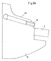
支持体工具には、それぞれ符号8が付されており、この支持体工具8は、カッタープレート2を取り付けるための切欠きを有している。図1a及び図1bに示したカッタープレート2は、円形の緊締用凹部9を有していて、この緊締用凹部9内には、球形若しくは円形の隆起部30が配置されている。この隆起部30の最高点は、緊締用凹部9の底部の上側であり且つカッタープレート上面の下側、若しくはすくい面の下側に配置されている。
Each support tool is denoted by
図1aに見られるように、好適には第1の緊締用凹部9に対して同軸的に、第2の緊締用凹部10が配置されており、この場合、第1の緊締用凹部9は、第2の緊締用凹部10よりも低く配置されており、且つ両緊締用凹部9,10は、カッタープレート上面よりも低く配置されている。これにより、第2の緊締用凹部10に対する第1の緊締用凹部9の高さ距離は、カッタープレート上面を研削加工又はラッピング加工した場合でも、常に同じである。
As can be seen in FIG. 1 a, a
カッタープレート2を支持体工具8に取り付けるために、この支持体工具8には緊締部材1が、緊締ねじ3を介して取り付けられている。緊締ねじ3は緊締部材1を貫通して、支持体工具8に設けられた緊締部材穴5に螺入されている。
In order to attach the
緊締ねじ3を螺入する際に、緊締部材1の先端がカッタープレート2を押圧する。1つの緊締用凹部9を備えたカッタープレート2を使用する場合は、緊締部材1の、カッタープレート2に面した下面に、突起又は鎌状部材として加工成形された、係合部材11が配置されている。この係合部材11は、緊締用凹部9に係合し、これによりカッタープレート2を支持体工具8に固定する。係合部材11は、突起又は鎌状部材としての形態だけでなく、原則として考えられる全ての形態を有することができ、また、係合部材無しの(つまり平滑な)緊締部材1も可能である。但し、係合部材無しの緊締部材1を使用する場合は、スローアウェイ(刃先交換)型カッタープレートの戻りが生ぜしめられることはない。
When the tightening
本発明では、緊締部材1(図2a、図2b及び図2c参照)は両側を支持体工具8に沿ってガイドされている。ガイド用に、一方では支持体工具8にガイドとして溝6が配置されており、且つ他方では緊締部材1にガイド面14が配置されており、溝6とガイド面14は許容誤差を狭くされていて、緊締部材1を輪郭移行部12まで、面状にガイドしている。図2aに、ガイド長さL、ガイド幅B及びこれらの範囲が示されている。ガイド長さLは、好適には(構成サイズに応じて)10〜22mmであり、ガイド幅Bは、(構成サイズに応じて)10〜20mmである。支持体工具8におけるガイド幅Bの許容誤差は、B±0.025であり、緊締部材1の幅の許容誤差は、B±0.05である。図2cには特にガイド面14が示されている。
In the present invention, the tightening member 1 (see FIGS. 2a, 2b and 2c) is guided along the
これにより、ガイドは緊締部材先端部13の極めて近くまで行われるようになっている。これにより、緊締部材輪郭若しくは係合部材11の、カッタープレート2の第1の緊締用凹部9への確実な係合が保証されている。つまり、緊締部材1の位置は、空間(機械)の工具位置に関係無く、常に同じ(回動することはない)なので、カッタープレートの交換は、例えば(工具に関して)オーバーヘッド位置においても、問題無く実施可能である。
As a result, the guide is performed very close to the
許容誤差を狭くしたガイドによって、過重な負荷の加工や、場合によっては一時的に生じる過剰負荷に際しても、緊締部材1はその位置が維持されるようになっている。これにより、「クラッシュ」した場合に、工具及び工作物の、場合によっては比較的大きな損傷を回避することができるようになっている。
The position of the tightening
図3には、緊締部材ヘッドの中心からカッタープレート(スローアウェイ型のカッタープレート)の中心まで、軸方向に引っ張る方向での緊締部材1の位置決めが、緊締部材に設けられた穴の公差と、緊締部材ねじとに基づき、自動的に生ぜしめられていることが示されている。このことは、カッタープレート2から見て緊締部材1の後ろ側の端部に、戻り斜面4が配置されており、且つこの戻り斜面4に適合された滑り斜面15が、緊締部材1に位置していることによって達成される。緊締部材1が緊締ねじ3により固定されると、滑り斜面15は戻り斜面4に沿って、緊締部材穴5の、カッタープレート2の側の壁が緊締ねじ3に当接するまで、滑り落ちる。緊締ねじ3に対する緊締部材穴5の壁の前記当接は、本発明の1つの重要な特徴である。それというのも、これにより、間隙Δ2=0となり(図3参照)、緊締ねじ3の長手方向軸線17からカッタープレート2の中心18までの間隔16が、常に同じ大きさになるからである。これにより、緊締部材1の下面に設けられた係合部材11が、正確に規定された位置において緊締用凹部9に係合することになる。このことは極めて重要である。それというのも、さもなければ不確定な力が、カッタープレート2に作用することになるからである。戻り斜面4及び滑り斜面15の角度は、好適には水平線に対して20度である。
In FIG. 3, the positioning of the tightening
高いプロセス確実性は、側方ガイドの他に、主に戻り斜面4による緊締部材1の戻り(図3又は図4a参照)、緊締部材輪郭若しくは係合部材と、カッタープレート(スローアウェイ型カッタープレート)との間の形状接続(形状的な束縛、例えば係合による結合)、並びに緊締用凹部9の中心の正面での係合部材11(緊締部材突起)の押圧(例えば図1a参照)によって得られる。これらの条件に基づいて、スローアウェイ型カッタープレートは回動不能に、プレート座に引き込まれる(図4a参照)。「緊締用凹部9の中心の正面」とは、係合部材11が、切刃縁部から見て、緊締用凹部9の中心の正面で、緊締用凹部9に形状接続的に係合することを意味しており、これにより、カッタープレート2の「上向き傾動」が排除されている。
In addition to the side guides, the high process reliability is achieved mainly by the return of the
図5には、緊締部材1の戻りが、ねじ軸部に対する緊締部材穴5(図6)の突き当たりを介して制限されていることが示されている。これにより、緊締用凹部9からの緊締部材1の滑り出しが阻止され、且つシステム全体、即ち、緊締部材−ねじ−工具が緊締されるようになっている。カッタープレート2は、支持部材27(支持プレート)に着座しており、支持部材27は、ねじ28によって支持体工具8に固定されている。
FIG. 5 shows that the return of the tightening
プロセスを確実にするカッタープレート2の緊締に関して基本的に重要なのは、緊締部材1において選択される長さ(てこ腕)の比である。本発明による工具システムは、1:1.7の比で設計されている(図6参照)。これにより、閉鎖力として導入されたねじ力の37%が、カッタープレートに作用することが達成される。
What is fundamentally important for the clamping of the
選択された軸方向距離寸法「X」(図6参照)は、最小サイズの緊締部材1によって(バリエーション最小化)、工具システムにとって重要であり且つ市場において汎用の、あらゆるカッタープレート幾何学形状やサイズを技術的に申し分なく、本発明による工具システム内に緊締することを考慮した結果である。3つの異なる軸方向距離寸法(X=13.3mm、X=16.15mm、X=21.5mm)を有する、3つの緊締部材サイズが有利であるということが判っている。これらは、内接円が9.52mm〜25.40mmの、あらゆるスローアウェイ型カッタープレートの幾何学形状をカバーする。長さ(てこ腕)比は、全てにおいて1:1.7である。 The selected axial distance dimension “X” (see FIG. 6) is determined by the smallest size clamping member 1 (variation minimization), which is important for the tool system and is universal on the market for all cutter plate geometries and sizes This is a result of considering the tightening in the tool system according to the present invention. It has been found that three clamping member sizes with three different axial distance dimensions (X = 13.3 mm, X = 16.15 mm, X = 21.5 mm) are advantageous. These cover all throwaway cutter plate geometries with inscribed circles between 9.52 mm and 25.40 mm. The length (lever arm) ratio is 1: 1.7 in all cases.
バリエーション最小化を考慮しない場合は、1.0〜1.7未満の比が、技術的にはより良好である。つまり、1:1の比では、導入されたねじ力の半分が、カッタープレートを押圧することになる。1.7〜2.2の範囲は、技術的には可能である。しかしながら、この比が大きければ大きいほど、カッタープレートに作用する力は小さくなる。例えば、緊締ねじ3が、力FSchraube=10.000Nで緊締部材1を押圧する場合、この力は、本発明では好適には斜面15に対する力FASchraube=6.300Nと、カッタープレート2に対する力FWSPSchraube=3.700Nとに分かれる。それというのも、6.300N=3.700N×1.7だからである。
If variation minimization is not considered, a ratio of 1.0 to less than 1.7 is technically better. That is, at a 1: 1 ratio, half of the introduced screw force presses the cutter plate. A range of 1.7 to 2.2 is technically possible. However, the greater this ratio, the smaller the force acting on the cutter plate. For example, when the tightening
FASchraube〜FSchraubeの距離が1である場合、本発明ではFSchraube〜FWSPSchraubeの距離は、好適には1.7である。このことは図6に示されている。 When the distance from F ASchraube to F Schraube is 1, in the present invention, the distance from F Schraube to F WSPSchraube is preferably 1.7. This is illustrated in FIG.
また、1:1.6〜1:1.8の範囲も好適である。 A range of 1: 1.6 to 1: 1.8 is also suitable.
カッタープレート交換に際して緊締ねじ3を下側から取り外せるようにするために、緊締ねじ3は、ねじ端部に外側六角体29を備えて形成されている(図7参照)。このことは、工具が例えば機械内でオーバーヘッド位置にある場合に必要である。M6用にはSW4の二面幅が算出された。M6の場合はSW4.5の二面幅も可能である。M8用にはSW5.5の二面幅が選択される。M8の場合は、SW5〜SW6の範囲の二面幅が可能である。緊締部材穴5は支持体工具8を貫通しているので、緊締ねじ3のねじ端部に到達(アクセス)することができるようになっている。
In order to allow the tightening
以下に、材料及び工具ホルダを列挙する:
−支持体工具8は、好適には調質鋼又は熱間加工用鋼の材料から成っている
−緊締部材1は、好適には以下の材料から成っている:
−鋼 500−750HV
−超硬合金 850−1250HV
−セラミック 1250−1650HV
−緊締部材は、以下のバリエーションで構造的に複合材料としても形成可能である:
−鋼から成る支持体工具及び超硬合金から成るカバー
−鋼から成るベース支持体及びセラミックから成るカバー
−CMS,HSK,KM,FTC,VDI,SK xxx等の、あらゆる慣用の工具ホルダシステムが可能である。
−本発明による工具システムは、シャンクツール、ボーリングバー、カートリッジ等の、あらゆる慣用の工具タイプにも適用可能である。
The following is a list of materials and tool holders:
The
-Steel 500-750HV
-Cemented carbide 850-1250HV
-Ceramic 1250-1650HV
-Fastening members can also be structurally formed as composite materials with the following variations:
-Support tool made of steel and cover made of cemented carbide.
-Base support made of steel and cover made of ceramic-Any conventional tool holder system is possible, such as CMS, HSK, KM, FTC, VDI, SK xxx.
The tool system according to the invention is applicable to any conventional tool type, such as shank tools, boring bars, cartridges, etc.
本発明の有利な実施形態では、支持体工具8内に、冷却媒体供給部が組み込まれている。この冷却媒体供給部は、図8a〜図8dに示されている。冷却媒体供給部は、2つの側方の緊締部材ガイド19内に組み込まれている(図8a及び図8b)。これにより冷却媒体は、目標の極めて近くに方向付けられて、切削プロセスにもたらされることになる。切りくずの滑落は、複数の移行半径を有する傾斜面20を介して可能である。カッタープレート上面に対する傾斜面20の傾斜角度α(図8d)は、3〜10度である。これにより、以前は頻繁に冷却媒体管において見られた(連続)チップの引っかかりが排除されている。傾斜面20の高さHは、好適には4〜8mmである(図8c)。
In an advantageous embodiment of the invention, a cooling medium supply is incorporated in the
冷却媒体用の流出開口及び穴のサイズは、工具サイズに応じて2〜10mmである。流出開口には、存在し得る閉鎖ねじのためのねじ山が形成されている。 The size of the outlet opening and the hole for the cooling medium is 2 to 10 mm depending on the tool size. The outflow opening is formed with a thread for a possible closing screw.
しかしまた、流出開口に、円錐形の先端部と中心穴とを備えたノズル31(図8e参照)を螺入する可能性もある。穴の直径は、工具の構成サイズに応じてφ1mm〜6mmで変化する。このノズルは、冷却媒体圧力が20bar未満であり且つ「オリジナルの」冷却媒体穴が汚染(閉塞)されやすい場合に使用される。これにより、加工プロセスにおける冷却媒体流量が十分である限りは、冷却媒体の流出速度の増大も達成される。 However, there is also a possibility that a nozzle 31 (see FIG. 8e) having a conical tip and a center hole is screwed into the outflow opening. The diameter of the hole varies between 1 mm and 6 mm depending on the tool configuration size. This nozzle is used when the coolant pressure is less than 20 bar and the “original” coolant hole is prone to contamination (clogging). Thereby, as long as the cooling medium flow rate in the machining process is sufficient, an increase in the cooling medium flow rate is also achieved.
本発明による工具システムは、モノブロック工具としても、アダプタを備えた工具としても想定されている。図9aには、モノブロック工具としての工具システムが示されており、図9bには、アダプタを備えた工具としての工具システムが示されている。図9aに示したモノブロック工具は、図1aに示した工具システムと同一である。以下に、図9bに示した工具システムを、図10a〜図10dに基づき詳しく説明する。 The tool system according to the invention is envisaged both as a monoblock tool and as a tool with an adapter. FIG. 9a shows a tool system as a monoblock tool, and FIG. 9b shows a tool system as a tool with an adapter. The monoblock tool shown in FIG. 9a is identical to the tool system shown in FIG. 1a. Hereinafter, the tool system shown in FIG. 9b will be described in detail with reference to FIGS. 10a to 10d.
アダプタ7(図10a〜図10b参照)内には、プロセスを確実にするカッタープレート2の緊締機能が全て組み込まれている。アダプタ7は、支持体工具8にねじで固定されるので、2つのねじ穴21を有している。更にアダプタ7は、緊締ねじ3用の穴22を有している。緊締部材1をガイドするために、アダプタ7は側方のアダプタガイド23と、アダプタ戻り斜面24と、場合によってはモノブロック工具と同様の冷却媒体供給部とを有している。冷却媒体供給部の流出開口25及び穴は、アダプタサイズに応じて2mm〜5mmである。冷却媒体供給は、アダプタガイド23を通じて行われる。アダプタ戻り斜面24は、アダプタの後ろ側の端部に配置されている。アダプタの高さは10mmであり、アダプタガイド23の高さは6mmである。好適な実施形態の寸法は、図10c及び図10dから看取され得る。アダプタ7の、カッタープレート2に面した側には、カッタープレートの形状に応じてプレート座壁26が配置されており、これらのプレート座壁26にカッタープレート2が、図10cに示したように当接する。
The adapter 7 (see FIGS. 10a to 10b) incorporates all the clamping functions of the
前記側方のガイド及び戻り斜面(20度)は、(工具にではなく)意図的にアダプタに組み込まれており、これにより、緊締部材とカッタープレート中心との心合わせ/同軸性/平行性が正確に一致するようになっている。アダプタは、熱間加工用鋼から製造される。 Said side guides and return bevels (20 degrees) are intentionally incorporated into the adapter (not to the tool), so that the centering / coaxiality / parallelism of the clamping member and the center of the cutter plate is achieved. Matches exactly. The adapter is manufactured from hot work steel.
Claims (12)
d.前記緊締部材(1)が、互いに平行な緊締部材ガイド(19)の溝(6)内に配置されており、該溝(6)内で前記緊締部材(1)は、緊締方向に移動可能に案内されており、前記緊締部材(1)は、2つの平行なガイド面(14)を有しており、これらのガイド面(14)が、前記緊締部材ガイド(19)に面状に接触することにより、前記緊締部材(1)の両側が、前記溝(6)内で案内されるようになっており、
e.前記緊締部材(1)内に、前記緊締ねじ(3)用の緊締部材穴(5)が配置されており、前記カッタープレート(2)が締め込まれた状態において、前記緊締部材穴(5)の、前記カッタープレート(2)側の壁が、前記緊締ねじ(3)に当接するようになっており、
f.前記係合部材(11)は、前記カッタープレート(2)の切刃縁部から見て、前記緊締用凹部(9)の中心の正面で、該緊締用凹部(9)に形状接続的に係合するようになっている
ことを特徴とする、切削工具システム。 A cutting tool system comprising a support tool (8), a cutter plate (2) with a clamping recess (9) and a clamping member (1) with an associated clamping screw (3). An engaging member (11) is disposed on the lower surface of the member (1) facing the cutter plate (2), and the engaging member (11) is tightened in the attached state by the tightening action (9). So that the cutter plate (2) is fixed, and the tightening member (1) is pulled in the tightening direction when the tightening screw (3) is tightened. In what is guided through the slope,
d. The tightening member (1) is disposed in the groove (6) of the tightening member guide (19) parallel to each other, and the tightening member (1) is movable in the tightening direction in the groove (6). The tightening member (1) is guided and has two parallel guide surfaces (14), and these guide surfaces (14) contact the tightening member guide (19) in a planar shape. Thus, both sides of the tightening member (1) are guided in the groove (6),
e. A tightening member hole (5) for the tightening screw (3) is disposed in the tightening member (1), and the tightening member hole (5) is in a state where the cutter plate (2) is tightened. The wall on the cutter plate (2) side comes into contact with the tightening screw (3),
f. The engagement member (11) is engaged with the tightening recess (9) in a shape-connecting manner in front of the center of the tightening recess (9) when viewed from the cutting edge of the cutter plate (2). A cutting tool system characterized by being adapted to each other.
Applications Claiming Priority (3)
| Application Number | Priority Date | Filing Date | Title |
|---|---|---|---|
| DE102011085250 | 2011-10-26 | ||
| DE102011085250.6 | 2011-10-26 | ||
| PCT/EP2012/071097 WO2013060752A1 (en) | 2011-10-26 | 2012-10-25 | Tool system |
Publications (1)
| Publication Number | Publication Date |
|---|---|
| JP2014534082A true JP2014534082A (en) | 2014-12-18 |
Family
ID=47074729
Family Applications (1)
| Application Number | Title | Priority Date | Filing Date |
|---|---|---|---|
| JP2014537604A Pending JP2014534082A (en) | 2011-10-26 | 2012-10-25 | Tool system |
Country Status (12)
| Country | Link |
|---|---|
| US (1) | US9669467B2 (en) |
| EP (1) | EP2771142B1 (en) |
| JP (1) | JP2014534082A (en) |
| KR (1) | KR20140094573A (en) |
| CN (1) | CN103998166B (en) |
| CA (1) | CA2853191A1 (en) |
| DE (1) | DE102012219490A1 (en) |
| ES (1) | ES2585210T3 (en) |
| IL (1) | IL232151A0 (en) |
| IN (1) | IN2014CN03850A (en) |
| PL (1) | PL2771142T3 (en) |
| WO (1) | WO2013060752A1 (en) |
Cited By (4)
| Publication number | Priority date | Publication date | Assignee | Title |
|---|---|---|---|---|
| JP2015093380A (en) * | 2013-11-14 | 2015-05-18 | サンドビック ツーリング フランス | Cartridge for grooving tool holder, corresponding grooving tool holder, kit and assembly thereof |
| WO2018034339A1 (en) * | 2016-08-19 | 2018-02-22 | 京セラ株式会社 | Cutting tool and method for manufacturing cut product using same |
| JP2019206075A (en) * | 2018-05-29 | 2019-12-05 | セラムテック ゲゼルシャフト ミット ベシュレンクテル ハフツングCeramTec GmbH | Tool system |
| JP2020511322A (en) * | 2017-03-22 | 2020-04-16 | セラムテック ゲゼルシャフト ミット ベシュレンクテル ハフツングCeramTec GmbH | Tool system |
Families Citing this family (7)
| Publication number | Priority date | Publication date | Assignee | Title |
|---|---|---|---|---|
| WO2016068120A1 (en) * | 2014-10-29 | 2016-05-06 | 京セラ株式会社 | Holder, cutting tool, and method for producing cut object |
| SI3242764T1 (en) * | 2015-01-09 | 2022-04-29 | Ceram Tec Gmbh | Carrier tool |
| EP3274116B1 (en) * | 2015-03-23 | 2019-06-26 | Ferraresso, Claudio | Tool holder, in particular turning tool holder, with rapid locking system for interchangeable inserts |
| US10946452B2 (en) * | 2015-06-30 | 2021-03-16 | Seco Tools Ab | Cutting tool and a nozzle with internally extending grooves |
| CN105234467A (en) * | 2015-09-09 | 2016-01-13 | 温州瑞明工业股份有限公司 | Cutter used for machining through hole with chamfer |
| JP6436322B2 (en) * | 2015-09-29 | 2018-12-12 | 株式会社タンガロイ | Cutting insert fixing member and cutting tool |
| AT16570U1 (en) * | 2018-08-01 | 2020-01-15 | Ceratizit Austria Gmbh | Rotary tool holder |
Citations (12)
| Publication number | Priority date | Publication date | Assignee | Title |
|---|---|---|---|---|
| US3268977A (en) * | 1964-02-13 | 1966-08-30 | Leroy H Diemond | Tool holder and insert |
| JPS4716045Y1 (en) * | 1969-07-24 | 1972-06-06 | ||
| JPS58188101U (en) * | 1982-06-10 | 1983-12-14 | 株式会社リコー | Bit holder |
| US4848198A (en) * | 1988-04-21 | 1989-07-18 | Kennametal Inc. | Chip breaking tool holder |
| JPH01125103U (en) * | 1988-02-18 | 1989-08-25 | ||
| EP0402934A2 (en) * | 1989-06-15 | 1990-12-19 | Mitsubishi Materials Corporation | Tool with clamped insert |
| JPH0631905U (en) * | 1992-09-30 | 1994-04-26 | 三菱マテリアル株式会社 | Indexable cutting tool |
| JPH0740051U (en) * | 1993-12-28 | 1995-07-18 | 日立精機株式会社 | High-pressure coolant nozzle adjustment device |
| JPH09183002A (en) * | 1995-12-29 | 1997-07-15 | Sumitomo Electric Ind Ltd | Internally lubricated cutting tool |
| JP2007203437A (en) * | 2006-02-06 | 2007-08-16 | Mitsubishi Materials Corp | Clamp mechanism for cutting insert, insert attachment and detachment type cutting tool, and cutting insert |
| WO2008062825A1 (en) * | 2006-11-22 | 2008-05-29 | Mitsubishi Materials Corporation | Insert/detachable type cutting tool and insert |
| JP2010520065A (en) * | 2007-02-28 | 2010-06-10 | セラムテック アクチエンゲゼルシャフト | Plate sheet adapter |
Family Cites Families (17)
| Publication number | Priority date | Publication date | Assignee | Title |
|---|---|---|---|---|
| US2062607A (en) * | 1935-05-29 | 1936-12-01 | O K Tool Co Inc | Streamlined bit clamp and holder |
| US3102326A (en) * | 1960-04-20 | 1963-09-03 | Alfred R Conti | Cutting tool |
| US3548475A (en) * | 1967-06-21 | 1970-12-22 | Usag Utensilerie Spa | Cutting tool for lathes |
| US3484920A (en) * | 1968-06-21 | 1969-12-23 | Eric J Werner | Chipbreaker and toolholder |
| FR2134944A5 (en) | 1971-04-22 | 1972-12-08 | Carmona Jean | |
| DE7831988U1 (en) * | 1978-10-27 | 1980-04-03 | Komet Stahlhalter- Und Werkzeugfabrik Robert Breuning Gmbh, 7122 Besigheim | CLAMPING DEVICE FOR CLAMPING AN INSERT INSERT TO A TOOL HOLDER |
| US4286902A (en) | 1980-01-09 | 1981-09-01 | Dresser Industries, Inc. | Self-colleting drill |
| DE3343448A1 (en) * | 1983-12-01 | 1985-06-13 | Hochmuth + Hollfelder, 8500 Nürnberg | CUTTING TOOL FOR METAL MACHINING |
| US4730525A (en) * | 1986-05-01 | 1988-03-15 | General Electric Company | Indexable cutting tool |
| IL84171A (en) * | 1987-10-14 | 1990-09-17 | Iscar Ltd | Cutting insert and tool holder therefor |
| DE3835961A1 (en) * | 1987-10-22 | 1989-05-03 | Mitsubishi Metal Corp | Tool firmly clamped or mounted in position |
| SE518027C2 (en) * | 2000-04-20 | 2002-08-20 | Sandvik Ab | Cutting tool system and means for precisely positioning the same |
| US7073986B2 (en) * | 2001-11-08 | 2006-07-11 | Kennametal Inc. | Dimpled insert with retaining clamp |
| DE102006052701A1 (en) | 2006-01-09 | 2007-07-26 | Ceramtec Ag Innovative Ceramic Engineering | Form-fitting mounted cutting plate on a support plate |
| CN100588527C (en) * | 2007-09-05 | 2010-02-10 | 机械科学研究总院先进制造技术研究中心 | Casting mould digital control cutting processing former |
| CN201086129Y (en) * | 2007-09-12 | 2008-07-16 | 广州机床厂有限公司 | Lathe |
| US9211590B2 (en) * | 2013-09-20 | 2015-12-15 | Kennametal Inc. | Screw head wedge clamp assembly for cutting tool |
-
2012
- 2012-10-25 IN IN3850CHN2014 patent/IN2014CN03850A/en unknown
- 2012-10-25 CA CA2853191A patent/CA2853191A1/en not_active Abandoned
- 2012-10-25 ES ES12778112.8T patent/ES2585210T3/en active Active
- 2012-10-25 DE DE102012219490A patent/DE102012219490A1/en not_active Withdrawn
- 2012-10-25 EP EP12778112.8A patent/EP2771142B1/en active Active
- 2012-10-25 KR KR1020147013928A patent/KR20140094573A/en not_active Application Discontinuation
- 2012-10-25 US US14/353,425 patent/US9669467B2/en active Active
- 2012-10-25 PL PL12778112T patent/PL2771142T3/en unknown
- 2012-10-25 WO PCT/EP2012/071097 patent/WO2013060752A1/en active Application Filing
- 2012-10-25 JP JP2014537604A patent/JP2014534082A/en active Pending
- 2012-10-25 CN CN201280064305.8A patent/CN103998166B/en active Active
-
2014
- 2014-04-22 IL IL232151A patent/IL232151A0/en unknown
Patent Citations (12)
| Publication number | Priority date | Publication date | Assignee | Title |
|---|---|---|---|---|
| US3268977A (en) * | 1964-02-13 | 1966-08-30 | Leroy H Diemond | Tool holder and insert |
| JPS4716045Y1 (en) * | 1969-07-24 | 1972-06-06 | ||
| JPS58188101U (en) * | 1982-06-10 | 1983-12-14 | 株式会社リコー | Bit holder |
| JPH01125103U (en) * | 1988-02-18 | 1989-08-25 | ||
| US4848198A (en) * | 1988-04-21 | 1989-07-18 | Kennametal Inc. | Chip breaking tool holder |
| EP0402934A2 (en) * | 1989-06-15 | 1990-12-19 | Mitsubishi Materials Corporation | Tool with clamped insert |
| JPH0631905U (en) * | 1992-09-30 | 1994-04-26 | 三菱マテリアル株式会社 | Indexable cutting tool |
| JPH0740051U (en) * | 1993-12-28 | 1995-07-18 | 日立精機株式会社 | High-pressure coolant nozzle adjustment device |
| JPH09183002A (en) * | 1995-12-29 | 1997-07-15 | Sumitomo Electric Ind Ltd | Internally lubricated cutting tool |
| JP2007203437A (en) * | 2006-02-06 | 2007-08-16 | Mitsubishi Materials Corp | Clamp mechanism for cutting insert, insert attachment and detachment type cutting tool, and cutting insert |
| WO2008062825A1 (en) * | 2006-11-22 | 2008-05-29 | Mitsubishi Materials Corporation | Insert/detachable type cutting tool and insert |
| JP2010520065A (en) * | 2007-02-28 | 2010-06-10 | セラムテック アクチエンゲゼルシャフト | Plate sheet adapter |
Cited By (9)
| Publication number | Priority date | Publication date | Assignee | Title |
|---|---|---|---|---|
| JP2015093380A (en) * | 2013-11-14 | 2015-05-18 | サンドビック ツーリング フランス | Cartridge for grooving tool holder, corresponding grooving tool holder, kit and assembly thereof |
| WO2018034339A1 (en) * | 2016-08-19 | 2018-02-22 | 京セラ株式会社 | Cutting tool and method for manufacturing cut product using same |
| JPWO2018034339A1 (en) * | 2016-08-19 | 2019-06-20 | 京セラ株式会社 | Cutting tool and method of manufacturing cut product using the same |
| US11065691B2 (en) | 2016-08-19 | 2021-07-20 | Kyocera Corporation | Cutting tool and method of manufacturing machined product using the same |
| JP2020511322A (en) * | 2017-03-22 | 2020-04-16 | セラムテック ゲゼルシャフト ミット ベシュレンクテル ハフツングCeramTec GmbH | Tool system |
| JP7167050B2 (en) | 2017-03-22 | 2022-11-08 | セラムテック ゲゼルシャフト ミット ベシュレンクテル ハフツング | tool system |
| US11504777B2 (en) | 2017-03-22 | 2022-11-22 | Ceramtec Gmbh | Tool system |
| JP2019206075A (en) * | 2018-05-29 | 2019-12-05 | セラムテック ゲゼルシャフト ミット ベシュレンクテル ハフツングCeramTec GmbH | Tool system |
| JP7330760B2 (en) | 2018-05-29 | 2023-08-22 | セラムテック ゲゼルシャフト ミット ベシュレンクテル ハフツング | tool system |
Also Published As
| Publication number | Publication date |
|---|---|
| DE102012219490A1 (en) | 2013-05-02 |
| CA2853191A1 (en) | 2013-05-02 |
| WO2013060752A1 (en) | 2013-05-02 |
| KR20140094573A (en) | 2014-07-30 |
| PL2771142T3 (en) | 2017-01-31 |
| CN103998166B (en) | 2016-05-25 |
| IL232151A0 (en) | 2014-05-28 |
| EP2771142A1 (en) | 2014-09-03 |
| ES2585210T3 (en) | 2016-10-04 |
| US20140294520A1 (en) | 2014-10-02 |
| US9669467B2 (en) | 2017-06-06 |
| CN103998166A (en) | 2014-08-20 |
| IN2014CN03850A (en) | 2015-09-04 |
| EP2771142B1 (en) | 2016-05-04 |
Similar Documents
| Publication | Publication Date | Title |
|---|---|---|
| JP2014534082A (en) | Tool system | |
| EP3059034B1 (en) | Tool holder and cutting tool | |
| JP5800017B2 (en) | Cutting insert clamping device, cutting tool and cutting insert | |
| JP6550759B2 (en) | Part-Time Job | |
| US8479622B2 (en) | Cutting tool assembly and tool holder therefor | |
| US7104171B1 (en) | Toolholder and toolholder assembly for a cutting insert positioned at a non-conventional height | |
| US10207329B2 (en) | Toolholder with clamp having fluid flow passages, and tool including such a toolholder | |
| US10384277B2 (en) | Tool body and cutting tool | |
| US10780505B2 (en) | Face grooving tool body for metal cutting | |
| KR102227667B1 (en) | Peripheral cutting tool utilizing stick blades | |
| JPH06511434A (en) | Cylindrical bottom milling cutter | |
| WO2016093275A1 (en) | Cutting insert, tool body, and cutting tool | |
| US10286459B2 (en) | Machining tool | |
| US20190001419A1 (en) | Carrier tool, cutting insert, and clamping element | |
| JP7167050B2 (en) | tool system | |
| JP7407793B2 (en) | drill tool | |
| US11059112B2 (en) | Milling tool | |
| US10369638B2 (en) | Milling cutter | |
| US10537947B2 (en) | Cutting tool and method for manufacturing cut workpiece | |
| JP2007253307A (en) | Milling cutter and insert | |
| JP2019206062A (en) | Rotary cutting tool and chip parting member | |
| JP2007253305A (en) | Milling cutter, and insert | |
| JP2018065195A (en) | Tip displacement type cutting tool |
Legal Events
| Date | Code | Title | Description |
|---|---|---|---|
| A621 | Written request for application examination |
Free format text: JAPANESE INTERMEDIATE CODE: A621 Effective date: 20151015 |
|
| A131 | Notification of reasons for refusal |
Free format text: JAPANESE INTERMEDIATE CODE: A131 Effective date: 20160808 |
|
| A02 | Decision of refusal |
Free format text: JAPANESE INTERMEDIATE CODE: A02 Effective date: 20170306 |