JP2014528362A - Miniaturized insert - Google Patents
Miniaturized insert Download PDFInfo
- Publication number
- JP2014528362A JP2014528362A JP2014533914A JP2014533914A JP2014528362A JP 2014528362 A JP2014528362 A JP 2014528362A JP 2014533914 A JP2014533914 A JP 2014533914A JP 2014533914 A JP2014533914 A JP 2014533914A JP 2014528362 A JP2014528362 A JP 2014528362A
- Authority
- JP
- Japan
- Prior art keywords
- insert
- tightening
- recess
- convex portion
- tip
- Prior art date
- Legal status (The legal status is an assumption and is not a legal conclusion. Google has not performed a legal analysis and makes no representation as to the accuracy of the status listed.)
- Granted
Links
Images

Classifications
-
- B—PERFORMING OPERATIONS; TRANSPORTING
- B23—MACHINE TOOLS; METAL-WORKING NOT OTHERWISE PROVIDED FOR
- B23B—TURNING; BORING
- B23B27/00—Tools for turning or boring machines; Tools of a similar kind in general; Accessories therefor
- B23B27/14—Cutting tools of which the bits or tips or cutting inserts are of special material
- B23B27/16—Cutting tools of which the bits or tips or cutting inserts are of special material with exchangeable cutting bits or cutting inserts, e.g. able to be clamped
- B23B27/1625—Cutting tools of which the bits or tips or cutting inserts are of special material with exchangeable cutting bits or cutting inserts, e.g. able to be clamped with plate-like cutting inserts of special shape clamped by a clamping member acting almost perpendicularly on the chip-forming plane
-
- B—PERFORMING OPERATIONS; TRANSPORTING
- B23—MACHINE TOOLS; METAL-WORKING NOT OTHERWISE PROVIDED FOR
- B23B—TURNING; BORING
- B23B27/00—Tools for turning or boring machines; Tools of a similar kind in general; Accessories therefor
- B23B27/14—Cutting tools of which the bits or tips or cutting inserts are of special material
- B23B27/16—Cutting tools of which the bits or tips or cutting inserts are of special material with exchangeable cutting bits or cutting inserts, e.g. able to be clamped
- B23B27/1644—Cutting tools of which the bits or tips or cutting inserts are of special material with exchangeable cutting bits or cutting inserts, e.g. able to be clamped with plate-like cutting inserts of special shape clamped by a clamping member acting almost perpendicularly on the chip-forming plane and at the same time upon the wall of a hole in the cutting insert
- B23B27/1651—Cutting tools of which the bits or tips or cutting inserts are of special material with exchangeable cutting bits or cutting inserts, e.g. able to be clamped with plate-like cutting inserts of special shape clamped by a clamping member acting almost perpendicularly on the chip-forming plane and at the same time upon the wall of a hole in the cutting insert characterised by having a special shape
-
- B—PERFORMING OPERATIONS; TRANSPORTING
- B23—MACHINE TOOLS; METAL-WORKING NOT OTHERWISE PROVIDED FOR
- B23B—TURNING; BORING
- B23B2200/00—Details of cutting inserts
- B23B2200/08—Rake or top surfaces
- B23B2200/086—Rake or top surfaces with one or more grooves
- B23B2200/088—Rake or top surfaces with one or more grooves for clamping
-
- B—PERFORMING OPERATIONS; TRANSPORTING
- B23—MACHINE TOOLS; METAL-WORKING NOT OTHERWISE PROVIDED FOR
- B23B—TURNING; BORING
- B23B2226/00—Materials of tools or workpieces not comprising a metal
- B23B2226/12—Boron nitride
- B23B2226/125—Boron nitride cubic [CBN]
-
- B—PERFORMING OPERATIONS; TRANSPORTING
- B23—MACHINE TOOLS; METAL-WORKING NOT OTHERWISE PROVIDED FOR
- B23B—TURNING; BORING
- B23B27/00—Tools for turning or boring machines; Tools of a similar kind in general; Accessories therefor
- B23B27/14—Cutting tools of which the bits or tips or cutting inserts are of special material
- B23B27/16—Cutting tools of which the bits or tips or cutting inserts are of special material with exchangeable cutting bits or cutting inserts, e.g. able to be clamped
-
- B—PERFORMING OPERATIONS; TRANSPORTING
- B23—MACHINE TOOLS; METAL-WORKING NOT OTHERWISE PROVIDED FOR
- B23B—TURNING; BORING
- B23B27/00—Tools for turning or boring machines; Tools of a similar kind in general; Accessories therefor
- B23B27/22—Cutting tools with chip-breaking equipment
-
- B—PERFORMING OPERATIONS; TRANSPORTING
- B23—MACHINE TOOLS; METAL-WORKING NOT OTHERWISE PROVIDED FOR
- B23B—TURNING; BORING
- B23B29/00—Holders for non-rotary cutting tools; Boring bars or boring heads; Accessories for tool holders
-
- Y—GENERAL TAGGING OF NEW TECHNOLOGICAL DEVELOPMENTS; GENERAL TAGGING OF CROSS-SECTIONAL TECHNOLOGIES SPANNING OVER SEVERAL SECTIONS OF THE IPC; TECHNICAL SUBJECTS COVERED BY FORMER USPC CROSS-REFERENCE ART COLLECTIONS [XRACs] AND DIGESTS
- Y10—TECHNICAL SUBJECTS COVERED BY FORMER USPC
- Y10T—TECHNICAL SUBJECTS COVERED BY FORMER US CLASSIFICATION
- Y10T407/00—Cutters, for shaping
- Y10T407/22—Cutters, for shaping including holder having seat for inserted tool
- Y10T407/2272—Cutters, for shaping including holder having seat for inserted tool with separate means to fasten tool to holder
- Y10T407/2282—Cutters, for shaping including holder having seat for inserted tool with separate means to fasten tool to holder including tool holding clamp and clamp actuator
Landscapes
- Engineering & Computer Science (AREA)
- Mechanical Engineering (AREA)
- Cutting Tools, Boring Holders, And Turrets (AREA)
- Clamps And Clips (AREA)
Abstract
本発明は、切削工具に用いられるインサート(4)であって、インサート上面(9)およびインサート下面(10)と、1つ以上の側面(13)と、該側面(13)へのインサート上面(9)の移行部に設けられたカッティングエッジ(6)と、インサート上面(9)に設けられた、外径d1を有する円形の緊締窪み(1)とを備えた、切削工具に用いられるインサートに関する。本発明によれば、製造コストを削減するために、緊締窪み(1)の外径d1が、2mm<d1≰6mm、好適には2mm<d1<5mmに設定されていることが提案される。The present invention is an insert (4) for use in a cutting tool, comprising an insert upper surface (9) and an insert lower surface (10), one or more side surfaces (13), and an insert upper surface on the side surface (13) ( The present invention relates to an insert used for a cutting tool, comprising a cutting edge (6) provided at a transition part of 9) and a circular tightening recess (1) having an outer diameter d1 provided on an insert upper surface (9). . According to the present invention, in order to reduce the manufacturing cost, it is proposed that the outer diameter d1 of the tightening recess (1) is set to 2 mm <d1≰6 mm, preferably 2 mm <d1 <5 mm.
Description
本発明は、切削工具に用いられるインサートであって、インサート上面およびインサート下面と、1つ以上の側面と、該側面へのインサート上面の移行部に設けられたカッティングエッジと、インサート上面に設けられた、外径d1を有する円形の緊締窪みとを備えた、切削工具に用いられるインサートに関する。 The present invention is an insert used for a cutting tool, and is provided on an insert upper surface, an insert lower surface, one or more side surfaces, a cutting edge provided at a transition portion of the insert upper surface to the side surface, and an insert upper surface. The present invention also relates to an insert used for a cutting tool, which is provided with a circular tightening recess having an outer diameter d1.
このようなインサートは、スローアウェイチップとも呼ばれ、欧州特許第1414607号明細書に記載されている。このインサートは切削工具に使用される。この切削工具は、主として、インサートを載置させるためのインサートシートを有する支持工具から成っている。インサートは、突起を備えた緊締駒によって支持工具に保持される。緊締駒は緊締ねじを介して支持工具に固定されている。緊締駒は、インサートに向けられた下面に直接的にまたは押圧片を介して突起を備えている。この突起は緊締窪み内に係合し、インサートを固定する。緊締窪みは円形に形成されており、中心には、凸部が位置している。この凸部の先端部は、窪みの底部よりは上側でインサート上面/インサート下面よりは下側に配置されている。 Such an insert, also called a throw-away tip, is described in EP 1414607. This insert is used for cutting tools. This cutting tool mainly includes a support tool having an insert sheet for placing the insert. The insert is held on the support tool by a fastening piece having a protrusion. The tightening piece is fixed to the support tool via a tightening screw. The tightening piece is provided with a protrusion directly on the lower surface facing the insert or via a pressing piece. This protrusion engages in the clamping recess and secures the insert. The tightening recess is formed in a circular shape, and a convex portion is located at the center. The tip of the convex portion is disposed above the bottom of the recess and below the insert upper surface / insert lower surface.
高脆性の工具材から成るインサートは、好適には、上述した、いわゆる「窪み緊締」を介して支持工具に緊締される。これによって、一般的に横断面の弱化に結び付けられる孔緊締を回避することができる。この弱化は、相応の荷重が加えられた際にインサートの破壊を招く。 The insert made of a highly brittle tool material is preferably clamped to the support tool via the so-called “dent clamp” described above. As a result, it is possible to avoid hole tightening that is generally associated with weakening of the cross section. This weakening causes the insert to break when a corresponding load is applied.
中実に形成されたPcBN(多結晶立方晶窒化ホウ素)インサートの場合には、インサートの体積が製造コストに対して特に重要となる。小さなインサートは、大幅なコスト削減ひいては経済性向上を意味する。PcBNは、制限された靭性を有するセラミック系の工具材に属している。より小さなインサートに孔を加工することは、通常、プロセス確実性における損失を意味する。その結果、インサートが頻繁に破壊される。規定の切削作業、たとえば伝動装置構成部材および軸受け構成部材のハードターニング加工の場合には、セラミック工具材だけでなく、PcBN工具材も使用することができる。上述した工具材から成るインサートの安全な交換可能性を提供する形状接続的な窪み緊締システムは知られていない。インサートシートへのインサートの確実な固定は、工具システムの安全な機能性に対する根本的な前提条件である。交換可能性を保証する工具システムに対する緊締窪みの設計時には、セラミックス内への窪みの押付け可能性だけでなく、超硬のPcBNから手間をかけて除去加工されなければならない最小限の体積にも注意を払わなければならない。PcBNとは、多結晶立方晶窒化ホウ素を意味している。 In the case of solidly formed PcBN (polycrystalline cubic boron nitride) inserts, the volume of the inserts is particularly important for manufacturing costs. Small inserts mean significant cost savings and thus economic improvements. PcBN belongs to a ceramic tool material having limited toughness. Machining holes in smaller inserts usually means a loss in process certainty. As a result, the insert is frequently broken. In the case of a prescribed cutting operation, for example, hard turning of a transmission component member and a bearing component member, not only a ceramic tool material but also a PcBN tool material can be used. There is no known shape-connected indentation clamping system that provides safe interchangeability of inserts made of the above-described tool material. Reliable fastening of the insert to the insert sheet is a fundamental prerequisite for the safe functionality of the tool system. When designing a clamp cavity for a tool system that guarantees interchangeability, pay attention not only to the ability to press the cavity into the ceramics, but also to the minimum volume that must be removed from the carbide PcBN. Have to pay. PcBN means polycrystalline cubic boron nitride.
本発明の課題は、請求項1の上位概念部に記載のインサートを改良して、インサートの製造コストが減じられているようにすることである。
An object of the present invention is to improve the insert described in the superordinate conceptual part of
この課題は、本発明によれば、小型化されたインサートによって達成される。本発明によれば、前述した課題は、緊締窪みの外径d1が、2mm<d1≦6mm、好適には2mm<d1<5mmに設定されていることによって解決される。驚くべきことに、このように小さな緊締窪みを備えたインサートは、工具に確実にかつ不動に挟着することができ、切削加工時にインサートシートから引き出されないことが判った。小さな緊締窪みを備えたインサートは小さく製造することができる。なぜならば、緊締が緊締窪みを介して行われるからである。より小さなインサートによって、材料がより少なくなる。これによって、製造コストが最小限に抑えられている。 This object is achieved according to the invention by a miniaturized insert. According to the present invention, the above-described problem is solved by setting the outer diameter d1 of the tightening recess to 2 mm <d1 ≦ 6 mm, preferably 2 mm <d1 <5 mm. Surprisingly, it has been found that an insert with such a small clamping recess can be securely and immovably clamped to the tool and is not pulled out of the insert sheet during cutting. An insert with a small clamping recess can be made small. This is because tightening is performed through the tightening recess. Smaller inserts result in less material. This minimizes manufacturing costs.
クランプを改善するためには、緊締窪みに、内部に位置する円形の凸部が配置されており、この凸部の先端部が、緊締窪みの底部よりは上側でインサート上面よりは下側に位置しており、凸部が、外径d2と、緊締窪みの底部から凸部の先端部までの高さhとを有しており、凸部の外径d2が、凸部の半分の高さhにおいて測定されており、凸部の外径d2が、0.8mm<d2<3.5mmに設定されている。凸部と、緊締窪みのサイズに関連した凸部のサイズとによって、クランプが最適化されている。 In order to improve the clamp, a circular protrusion located inside is arranged in the tightening recess, and the tip of this protrusion is located above the bottom of the tightening recess and below the top surface of the insert. The convex portion has an outer diameter d2 and a height h from the bottom of the tightening recess to the tip of the convex portion, and the outer diameter d2 of the convex portion is half the height of the convex portion. Measured at h, the outer diameter d2 of the convex portion is set to 0.8 mm <d2 <3.5 mm. The clamp is optimized by the projection and the size of the projection relative to the size of the clamping recess.
好適には、インサートが、そのインサート下面にインサート上面と同じ緊締窪みを有していて、ひいては、スローアウェイチップとして形成されている。 Preferably, the insert has the same tightening recess as the upper surface of the insert on the lower surface of the insert, and thus is formed as a throw-away tip.
好適な態様では、インサートが、PcBN(多結晶立方晶窒化ホウ素)から成っている。この材料は極めて高価である。これによって、より小さなインサートが大幅なコスト削減に繋がる。 In a preferred embodiment, the insert consists of PcBN (polycrystalline cubic boron nitride). This material is very expensive. This results in a significant cost reduction with smaller inserts.
好適な態様では、緊締窪みが、V<8mm3、好適にはV<6mm3の容積Vを有している。公知先行技術、たとえば欧州特許第1414607号明細書に記載の緊締窪みの容積は、数倍だけ高く設定されている。 In a preferred embodiment, the tightening recess has a volume V of V <8 mm 3 , preferably V <6 mm 3 . The volume of the tightening recess described in the known prior art, for example EP 1414607, is set several times higher.
インサートの挟着された状態で凸部に対する緊締駒の突起のスリップを阻止しかつ押付け可能性を高めるために、好適には、凸部の先端部が、インサート上面の垂線に対して凸部角α1を成して傾けられた側面を介して、緊締窪みの底部に移行しており、凸部角α1が、7°<α1<55°、好適には7°<α1<35°に設定されている。 In order to prevent slippage of the projection of the tightening piece with respect to the convex portion with the insert being sandwiched and to increase the possibility of pressing, it is preferable that the tip portion of the convex portion has a convex portion angle α1 with respect to the perpendicular to the upper surface of the insert. And the convex portion angle α1 is set to 7 ° <α1 <55 °, preferably 7 ° <α1 <35 °. Yes.
特殊な態様では、凸部角α1に対して、27°<α1<28°が選択されている。凸部に対する緊締駒の突起のスリップは、いかなる用途でも生じない。 In a special aspect, 27 ° <α1 <28 ° is selected for the convex portion angle α1. The slip of the projection of the tightening piece with respect to the convex portion does not occur in any application.
前述した全ての角度によって、α1<7°の時に比べて、押付け可能性が大幅に改善される。中心に配置された隆起部を介した公知先行技術に係る公知の緊締は、著しく低い位置で行われる。公知先行技術によれば、角度α1が、α1>>45°であり、60°以上である。このような低い隆起部では、押付け可能性は最適であるものの、引掛り効果ひいては確実な引込みならびに使用中のμm運動に対するインサートの位置固定が付与されていない。また、緊締駒5の突起11も低い隆起部に対して滑ってしまう。 All the above-mentioned angles greatly improve the pressing possibility as compared with the case of α1 <7 °. The known tightening according to the known prior art via a centrally located ridge is performed at a significantly lower position. According to the known prior art, the angle α1 is α1 >> 45 ° and is greater than 60 °. With such a low ridge, the pushability is optimal, but the hooking effect and thus the reliable pull-in and the fixed position of the insert against the μm movement during use are not provided. Further, the projection 11 of the tightening piece 5 also slides against the low raised portion.
凸部は支持要素であり、スペース不足に基づき、極めて小さな直径d2を有しているので、幾何学的な設計は、力F1の伝達に対する剛性が十分であるように行われなければならない。特に高さh(図1参照)に対する直径d2の比が要求に適合されなければならない。好適には、凸部の高さh、すなわち、底部から凸部の先端部までの間隔が、2×d2≧h≧0.4×d2に設定されている。 Since the convex part is a support element and has a very small diameter d2 due to lack of space, the geometric design must be made so that it is sufficiently rigid for the transmission of the force F1. In particular, the ratio of the diameter d2 to the height h (see FIG. 1) must be adapted to the requirements. Preferably, the height h of the convex part, that is, the distance from the bottom part to the tip part of the convex part is set to 2 × d2 ≧ h ≧ 0.4 × d2.
好適には、凸部の先端部が、曲率半径r1を有する移行部を介して、側面に移行しており、この側面が、曲率半径r2を有する移行部を介して、緊締窪みの底部に移行しており、この緊締窪みの底部が、曲率半径r3を有する移行部を介して、緊締窪みの底部をインサート上面/インサート下面に接続する側面に移行しており、曲率半径r1、r2,r3が、0.05mm〜0.6mm、好適には0.2mm〜0.3mmに設定されている。 Preferably, the tip of the convex portion is shifted to the side surface via a transition portion having a radius of curvature r1, and this side surface is shifted to the bottom of the tightening recess via the transition portion having a radius of curvature r2. The bottom of the tightening recess is shifted to a side surface connecting the bottom of the tightening recess to the insert upper surface / insert lower surface via a transition portion having a radius of curvature r3, and the curvature radii r1, r2, r3 are , 0.05 mm to 0.6 mm, preferably 0.2 mm to 0.3 mm.
このことは、強度を高めるために有利である。移行部の曲率半径r1〜r3は、ある程度のサイズに達していなければならない。さもないと、目標破断箇所が生じてしまう。特に曲率半径r1は、緊締駒に設けられた突起と、緊締窪みに設けられた凸部との間に緊締面を形成することができるように選択されなければならない。緊締線または緊締点でさえ、増加させられた荷重を招いてしまう恐れがある。曲率半径r1〜r3は、0.05〜0.6mm、好適には0.2〜0.3mmに設定されている。こうして、緊締駒の突起の押圧面と協働して十分な強度を提供する十分に高い剛性を得ることができる。幾何学形状は、脆性のセラミックスに圧縮荷重が加えられるように設計されている。 This is advantageous for increasing strength. The radius of curvature r1 to r3 of the transition portion must reach a certain size. Otherwise, a target fracture location will occur. In particular, the curvature radius r1 must be selected so that a tightening surface can be formed between the protrusion provided on the tightening piece and the convex portion provided on the tightening recess. Even tightening lines or tightening points can lead to increased loads. The curvature radii r1 to r3 are set to 0.05 to 0.6 mm, preferably 0.2 to 0.3 mm. In this way, it is possible to obtain sufficiently high rigidity that provides sufficient strength in cooperation with the pressing surface of the projection of the tightening piece. The geometric shape is designed so that a compressive load is applied to the brittle ceramic.
前述したインサートの本発明に係る使用は、緊締窪み内に係合する突起が配置された緊締駒と、この緊締駒に設けられた、インサートのカッティングエッジから見て緊締窪みの手前でインサート上面/インサート下面に載置されるノーズとによるクランプである。 The above-described use of the insert according to the present invention includes a clamping piece in which a protrusion that engages in the clamping recess is disposed, and an insert upper surface / front surface of the insert before the clamping recess as viewed from the cutting edge of the insert provided on the clamping piece. It is a clamp with a nose placed on the lower surface of the insert.
好適な使用では、カッティングエッジから緊締駒のノーズまでの間隔aが、12.7mmの内接円を有するインサートでは少なくとも2.2mmに設定されていて、12.7mmよりも小さな内接円を有するインサートでは少なくとも1.3mmに設定されている。 In a preferred use, the insert a having an inscribed circle smaller than 12.7 mm, in which the distance a from the cutting edge to the nose of the clamping piece is set to at least 2.2 mm in an insert having an inscribed circle of 12.7 mm Then, it is set to at least 1.3 mm.
好適には、インサートが、焼入れ鋼を切削加工するために使用される。 Preferably, inserts are used to cut hardened steel.
以下、本明細書において用いられる概念の定義である。 Hereinafter, the concept used in this specification is defined.
角度α1は、インサート表面の垂線に対する凸部の側面の傾きを説明している。 The angle α1 describes the inclination of the side surface of the convex portion with respect to the perpendicular to the insert surface.
角度α2は、インサート表面の垂線に対して測定された、緊締窪みの縁部から緊締窪みの底部までの緊締窪みの傾きを説明している。 The angle α2 describes the inclination of the clamping recess from the edge of the clamping recess to the bottom of the clamping recess, measured with respect to the normal of the insert surface.
文字hは、緊締窪みの底部から凸部の最も高い点、すなわち、凸部の先端部までの凸部の高さを表している。 The letter h represents the height of the protrusion from the bottom of the tightening recess to the highest point of the protrusion, that is, the tip of the protrusion.
r1は、凸部の頭部もしくは先端部が(角度α1によって説明した)凸部の側面に移行する部分の曲率半径である。 r1 is the radius of curvature of the portion where the head or tip of the convex portion transitions to the side surface of the convex portion (explained by angle α1).
r2は、(角度α1によって説明した)凸部の側面が緊締窪みの底部に移行する部分の曲率半径である。 r2 is a radius of curvature of a portion where the side surface of the convex portion (explained by the angle α1) moves to the bottom of the tightening recess.
r3は、緊締窪みの底部が、角度α2によって説明した緊締窪みの側面に移行する部分の曲率半径である。 r3 is the radius of curvature of the portion where the bottom of the tightening recess transitions to the side of the tightening recess described by the angle α2.
以下に、本発明を2つの図面に基づき説明する。両図には、それぞれ本発明に係るインサートの横断面図が示してある。 In the following, the present invention will be described with reference to two drawings. In both figures, cross-sectional views of the insert according to the present invention are shown.
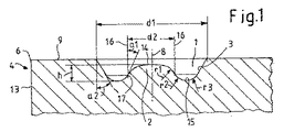
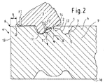
図1には、本発明に係るインサート4の中心8を通る断面図が示してあり、図2には、このインサート4が組付け状態、すなわち、緊締駒5によって係合された状態で示してある。
FIG. 1 shows a cross-sectional view through the center 8 of the
インサート4(図1および図2参照)が小さければ小さいほど、緊締窪み1を形成するための利用可能なスペースも小さくなる。この利用可能なスペースは、緊締駒5のノーズ12とカッティングエッジ6との間に形成される間隔aが考慮される場合に一層減少させられる(図2参照)。さらに、高精度の構成部材の場合には、数μm範囲のインサート4の運動も許容不能である。確実な固定には、緊締駒5によるインサート4の形状接続的な結合が必要となる。緊締面7がインサート4の中心8よりも前方に配置されていると、いわゆる「ずれ滑り」のリスクが減少させられる。「ずれ滑り」とは、緊締駒5に設けられた突起11(図2参照)がワークピースの加工時に凸部2に対してスリップすることを意味している。これに関連して、「中心8よりも前方」とは、突起11が、緊締窪み1の、カッティングエッジ6に近い方の側で緊締窪み1内に係合していることを意味している。凸部2の特別な構造によって、ずれ滑りを本発明により減少させることができる。凸部2は隆起部とも呼ばれる。
The smaller the insert 4 (see FIGS. 1 and 2), the smaller the available space for forming the
したがって、本発明の対象は、本発明における緊締窪み1を備えた小型化されたインサート4である。緊締窪み1は、d1≦6mm(「≦」は「以下」を意味している)、好適には2mm<d1<5mmの直径d1を有している(図1参照)。確実なクランプを保証するためには、凸部2の角度α1が、α1<55°に選択される。好適には、角度が7°<α1<35°に設定されている。図1および図2の特殊な形態では、角度が27°<α1<28°に規定されている。これによって、凸部2に対する緊締駒5の突起11のスリップが阻止される。緊締駒5に設けられた突起11は、力F2(図2参照)で引っ掛かっている。セラミックスの場合には、α1<7°の時に比べて、押付け可能性が大幅に改善されている。中心に配置された隆起部を介した公知先行技術に係る公知の緊締は、著しく低い位置で行われている。公知先行技術によれば、角度α1が、α1>>45°であり、60°以上である。このような低い隆起部では、押付け可能性は最適であるものの、引掛り効果ひいては確実な引込みならびに使用中のμm運動に対するインサート4の位置固定が付与されていない。また、緊締駒5の突起11も低い隆起部に対して滑ってしまう。
Therefore, the subject of the present invention is the
本発明における緊締窪み1の小さな直径d1によって、除去加工すべき体積が減じられる。PcBNの場合には、このような緊締窪み1が、大抵、手間のかかるレーザ加工法によって形成される。従来の緊締窪み1に比べて、体積を40%よりも多く減らすことができる。これによって、付加的な経済的な利点が得られる。凸部2は支持要素であり、スペース不足に基づき、極めて小さな直径d2を有しているので、幾何学的な設計は、力F1の伝達に対する剛性が十分であるように行われなければならない。特に高さh(図1参照)に対する直径d2の比が要求に適合されなければならない。比d/hは、最大で高さ2に対して直径1であってよい。好適には、d/hの比が1:1に設定されている。この特殊な形態では、比d/hが、高さ0.5に対して直径1である。強度を高めるためには、移行部の曲率半径r1〜r3(図1参照)が、ある程度のサイズに達していなければならない。さもないと、目標破断箇所が生じてしまう。特に曲率半径r1は、緊締駒5に設けられた突起11と凸部2との間に緊締面7を形成することができるように選択されなければならない。緊締線または緊締点でさえ、増加させられた荷重を招いてしまう恐れがある。曲率半径r1〜r3は、0.05〜0.6mm、好適には0.2〜0.3mmに設定されている。こうして、緊締駒5の突起11の押圧面と協働して十分な強度を提供する十分に高い剛性を得ることができる。幾何学形状は、脆性のセラミックスに圧縮荷重が加えられるように設計されている。こうして、(ここでは、この特殊で好適な形態において)d1=3mmの窪みサイズを確実に実現することが達成される。これによって、カッティングエッジ6に対する臨界的な間隔aを受け入れる必要なく、スローアウェイチップの中心8よりも前方の緊締駒5のノーズ12の支持面(図1参照)が可能となる。
The volume to be removed is reduced by the small diameter d1 of the tightening
緊締窪み1の容積Vは、好適にはV<8mm3、特に好適にはV<6mm3に設定されている。
The volume V of the tightening
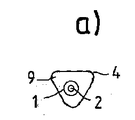
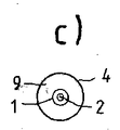
図3a、図3bおよび図3cには、本発明に係るインサート4の種々異なる形態が平面図で示してある。図3aには、円形の緊締窪み1と、この緊締窪み1内に配置された凸部2とを備えた三角形のインサート4が示してある。図3bには、円形の緊締窪み1と、この緊締窪み1内に配置された凸部2とを備えた正方形のインサート4が示してある。図3cには、円形の緊締窪み1と、この緊締窪み1内に配置された凸部2とを備えた円筒形のインサート4が示してある。
3a, 3b and 3c show different forms of the
Claims (12)
Applications Claiming Priority (3)
| Application Number | Priority Date | Filing Date | Title |
|---|---|---|---|
| DE102011084091.5 | 2011-10-06 | ||
| DE102011084091 | 2011-10-06 | ||
| PCT/EP2012/069705 WO2013050520A1 (en) | 2011-10-06 | 2012-10-05 | Miniaturized cutting plate |
Publications (2)
| Publication Number | Publication Date |
|---|---|
| JP2014528362A true JP2014528362A (en) | 2014-10-27 |
| JP6138139B2 JP6138139B2 (en) | 2017-05-31 |
Family
ID=47018993
Family Applications (1)
| Application Number | Title | Priority Date | Filing Date |
|---|---|---|---|
| JP2014533914A Expired - Fee Related JP6138139B2 (en) | 2011-10-06 | 2012-10-05 | Miniaturized insert |
Country Status (13)
| Country | Link |
|---|---|
| US (1) | US9770762B2 (en) |
| EP (1) | EP2763809B1 (en) |
| JP (1) | JP6138139B2 (en) |
| KR (1) | KR101990608B1 (en) |
| CN (1) | CN103987480B (en) |
| DE (1) | DE102012218193A1 (en) |
| DK (1) | DK2763809T3 (en) |
| ES (1) | ES2817782T3 (en) |
| HU (1) | HUE051769T2 (en) |
| PL (1) | PL2763809T3 (en) |
| PT (1) | PT2763809T (en) |
| SI (1) | SI2763809T1 (en) |
| WO (1) | WO2013050520A1 (en) |
Families Citing this family (3)
| Publication number | Priority date | Publication date | Assignee | Title |
|---|---|---|---|---|
| DE102014104886A1 (en) | 2014-04-07 | 2015-10-08 | Mas Gmbh | Cutting plate, cutting tool and method for producing a cutting plate |
| HUE057756T2 (en) * | 2015-01-09 | 2022-06-28 | Ceram Gmbh | Carrier tool |
| US11241747B2 (en) * | 2017-10-16 | 2022-02-08 | Iscar, Ltd. | Cutting tool and undersized bore-less indexable insert therefor |
Citations (8)
| Publication number | Priority date | Publication date | Assignee | Title |
|---|---|---|---|---|
| DE1602817A1 (en) * | 1967-09-20 | 1970-05-06 | Hans Heinlein | Insert arrangement |
| JPH1177408A (en) * | 1997-09-09 | 1999-03-23 | Sumitomo Electric Ind Ltd | Ceramic tip clamp type cutting tool |
| JP2002508260A (en) * | 1997-12-03 | 2002-03-19 | サンドビック アクティエボラーグ | Ceramic cutting insert |
| US20030086766A1 (en) * | 2001-11-08 | 2003-05-08 | Andras Linn R | Dimpled insert with retaining clamp |
| US20030219319A1 (en) * | 2002-03-21 | 2003-11-27 | Sandvik Aktiebolag | Tool for chip removing machining and rotatable cutting insert for such tools |
| JPWO2003015968A1 (en) * | 2001-08-10 | 2004-12-02 | 住友電気工業株式会社 | Ultra-high pressure sintered compact cutting tool having depressions or grooves, holding mechanism therefor, and method of manufacturing the same |
| JP2009101513A (en) * | 2001-07-26 | 2009-05-14 | Ceramtec Ag Innov Ceramic Eng | Cutting plate |
| WO2010069541A1 (en) * | 2008-12-19 | 2010-06-24 | MAPAL Fabrik für Präzisionswerkzeuge Dr. Kress KG | Reamer, cutter plates therefor and method for adjusting the machining diameter of a reamer of this type |
Family Cites Families (14)
| Publication number | Priority date | Publication date | Assignee | Title |
|---|---|---|---|---|
| DE4240295A1 (en) * | 1991-12-03 | 1993-06-09 | Ursula 7310 Plochingen De Groeschel | Clamp for securing throw-away tooltips in turning tool holder - has pulling ball clamp between depression in top face of tooltip and opposing thrust plate to seat tooltip in recess |
| DE4430171C2 (en) * | 1994-08-25 | 1996-08-14 | Walter Ag | Form-locked insert |
| DE19524945A1 (en) * | 1995-07-08 | 1997-01-09 | Cerasiv Gmbh | Cutting cutting tool |
| DE19854873A1 (en) * | 1998-11-27 | 2000-05-31 | Widia Gmbh | Cutter for tool used for cutting ceramics has cutter held in place by hooked clamp |
| WO2000064615A1 (en) * | 1999-04-26 | 2000-11-02 | Sandvik Aktiebolag | A tool holder and a clamp plate for holding a cutting insert |
| US6379087B1 (en) * | 2000-02-07 | 2002-04-30 | Kennametal Inc. | Cutting insert with split face clamping surfaces and toolholder therefor |
| DE10208266A1 (en) * | 2001-07-26 | 2003-02-13 | Ceram Tec Ag Innovative Cerami | Stock-removing cutting tool has circular clamping trough with centre protrusion on cutting plate associated with matching circular ring on cam of pressure member which engages round protrusion |
| DE10239451A1 (en) * | 2002-08-28 | 2004-03-11 | Ceramtec Ag Innovative Ceramic Engineering | Cutting plate for mounting in a cutting tool for cutting cast material, especially cast iron, comprises a cutting plate upper side, a cutting edge |
| US7429152B2 (en) * | 2003-06-17 | 2008-09-30 | Kennametal Inc. | Uncoated cutting tool using brazed-in superhard blank |
| SE530289C2 (en) * | 2006-10-13 | 2008-04-22 | Seco Tools Ab | Negative lathe with a phase between cutting edge and release side |
| DE102008001857A1 (en) | 2007-05-22 | 2008-11-27 | Ceramtec Ag | Plate seat with inserts |
| US7547163B2 (en) * | 2007-07-16 | 2009-06-16 | Kennametal Inc. | Clamping tool holder |
| US8236411B2 (en) * | 2008-03-26 | 2012-08-07 | Kyocera Corporation | Cutting tool |
| CN201432116Y (en) * | 2009-06-29 | 2010-03-31 | 株洲钻石切削刀具股份有限公司 | Fixed cartridges for indexable inserts |
-
2012
- 2012-10-05 HU HUE12772755A patent/HUE051769T2/en unknown
- 2012-10-05 SI SI201231832T patent/SI2763809T1/en unknown
- 2012-10-05 CN CN201280060005.2A patent/CN103987480B/en active Active
- 2012-10-05 PL PL12772755T patent/PL2763809T3/en unknown
- 2012-10-05 JP JP2014533914A patent/JP6138139B2/en not_active Expired - Fee Related
- 2012-10-05 US US14/348,632 patent/US9770762B2/en not_active Expired - Fee Related
- 2012-10-05 WO PCT/EP2012/069705 patent/WO2013050520A1/en not_active Ceased
- 2012-10-05 KR KR1020147012267A patent/KR101990608B1/en not_active Expired - Fee Related
- 2012-10-05 ES ES12772755T patent/ES2817782T3/en active Active
- 2012-10-05 EP EP12772755.0A patent/EP2763809B1/en active Active
- 2012-10-05 DK DK12772755.0T patent/DK2763809T3/en active
- 2012-10-05 PT PT127727550T patent/PT2763809T/en unknown
- 2012-10-05 DE DE102012218193A patent/DE102012218193A1/en not_active Withdrawn
Patent Citations (8)
| Publication number | Priority date | Publication date | Assignee | Title |
|---|---|---|---|---|
| DE1602817A1 (en) * | 1967-09-20 | 1970-05-06 | Hans Heinlein | Insert arrangement |
| JPH1177408A (en) * | 1997-09-09 | 1999-03-23 | Sumitomo Electric Ind Ltd | Ceramic tip clamp type cutting tool |
| JP2002508260A (en) * | 1997-12-03 | 2002-03-19 | サンドビック アクティエボラーグ | Ceramic cutting insert |
| JP2009101513A (en) * | 2001-07-26 | 2009-05-14 | Ceramtec Ag Innov Ceramic Eng | Cutting plate |
| JPWO2003015968A1 (en) * | 2001-08-10 | 2004-12-02 | 住友電気工業株式会社 | Ultra-high pressure sintered compact cutting tool having depressions or grooves, holding mechanism therefor, and method of manufacturing the same |
| US20030086766A1 (en) * | 2001-11-08 | 2003-05-08 | Andras Linn R | Dimpled insert with retaining clamp |
| US20030219319A1 (en) * | 2002-03-21 | 2003-11-27 | Sandvik Aktiebolag | Tool for chip removing machining and rotatable cutting insert for such tools |
| WO2010069541A1 (en) * | 2008-12-19 | 2010-06-24 | MAPAL Fabrik für Präzisionswerkzeuge Dr. Kress KG | Reamer, cutter plates therefor and method for adjusting the machining diameter of a reamer of this type |
Also Published As
| Publication number | Publication date |
|---|---|
| US20140234041A1 (en) | 2014-08-21 |
| PT2763809T (en) | 2020-09-04 |
| EP2763809A1 (en) | 2014-08-13 |
| CN103987480A (en) | 2014-08-13 |
| CN103987480B (en) | 2017-09-12 |
| DK2763809T3 (en) | 2020-09-07 |
| ES2817782T3 (en) | 2021-04-08 |
| WO2013050520A1 (en) | 2013-04-11 |
| HUE051769T2 (en) | 2021-03-29 |
| KR101990608B1 (en) | 2019-06-18 |
| JP6138139B2 (en) | 2017-05-31 |
| EP2763809B1 (en) | 2020-06-24 |
| SI2763809T1 (en) | 2020-10-30 |
| KR20140078727A (en) | 2014-06-25 |
| DE102012218193A1 (en) | 2013-04-11 |
| US9770762B2 (en) | 2017-09-26 |
| PL2763809T3 (en) | 2020-10-19 |
Similar Documents
| Publication | Publication Date | Title |
|---|---|---|
| JP5115148B2 (en) | Insert detachable cutting tool head member and insert detachable cutting tool | |
| JP5231396B2 (en) | Side locking insert and material removal tool using side locking insert | |
| JP5396539B2 (en) | Double-side indexable cutting insert and reinforcement assembly | |
| CN108602130B (en) | Face grooving tool body for metal cutting | |
| CN212793066U (en) | Tool for chip removing machining | |
| CN103998166B (en) | Tooling system | |
| CN105142833A (en) | Milling tool | |
| JP5040591B2 (en) | Insert detachable cutting tool head member and insert detachable cutting tool | |
| JP5488374B2 (en) | Replaceable head cutting tool | |
| WO2013057778A1 (en) | Holder for head replacement-type cutting tool, and head replacement-type cutting tool | |
| JP6138139B2 (en) | Miniaturized insert | |
| US9782841B2 (en) | Cutting tool | |
| CN107206505A (en) | Cutting tool | |
| US10415385B2 (en) | Pick, in particular a round-shank pick | |
| US10286459B2 (en) | Machining tool | |
| WO2013057776A1 (en) | Head replacement-type cutting tool | |
| JP6496744B2 (en) | Tools for machining workpieces | |
| US20190001419A1 (en) | Carrier tool, cutting insert, and clamping element | |
| CN109715327A (en) | Face milling cutter and its tangential cutting insert | |
| US20100158621A1 (en) | Cutting tool for recessing and grooving, comprising a replaceable abutment for the cutting element | |
| JP2003145320A (en) | Indexable insert and its clamping mechanism | |
| CN104741472A (en) | Plate material omnibearing locating structure and method in hot press forming technology | |
| JP2007290057A (en) | Ultra-high pressure sintered body cutting tool | |
| JP5071048B2 (en) | Insert detachable cutting tool head member and insert detachable cutting tool | |
| JP4741646B2 (en) | Throw away end mill and manufacturing method thereof |
Legal Events
| Date | Code | Title | Description |
|---|---|---|---|
| A621 | Written request for application examination |
Free format text: JAPANESE INTERMEDIATE CODE: A621 Effective date: 20150925 |
|
| A977 | Report on retrieval |
Free format text: JAPANESE INTERMEDIATE CODE: A971007 Effective date: 20160818 |
|
| A131 | Notification of reasons for refusal |
Free format text: JAPANESE INTERMEDIATE CODE: A131 Effective date: 20160829 |
|
| A521 | Request for written amendment filed |
Free format text: JAPANESE INTERMEDIATE CODE: A523 Effective date: 20161115 |
|
| TRDD | Decision of grant or rejection written | ||
| A01 | Written decision to grant a patent or to grant a registration (utility model) |
Free format text: JAPANESE INTERMEDIATE CODE: A01 Effective date: 20170403 |
|
| A61 | First payment of annual fees (during grant procedure) |
Free format text: JAPANESE INTERMEDIATE CODE: A61 Effective date: 20170425 |
|
| R150 | Certificate of patent or registration of utility model |
Ref document number: 6138139 Country of ref document: JP Free format text: JAPANESE INTERMEDIATE CODE: R150 |
|
| R250 | Receipt of annual fees |
Free format text: JAPANESE INTERMEDIATE CODE: R250 |
|
| R250 | Receipt of annual fees |
Free format text: JAPANESE INTERMEDIATE CODE: R250 |
|
| R250 | Receipt of annual fees |
Free format text: JAPANESE INTERMEDIATE CODE: R250 |
|
| R250 | Receipt of annual fees |
Free format text: JAPANESE INTERMEDIATE CODE: R250 |
|
| R250 | Receipt of annual fees |
Free format text: JAPANESE INTERMEDIATE CODE: R250 |
|
| LAPS | Cancellation because of no payment of annual fees |