JP5040591B2 - Insert detachable cutting tool head member and insert detachable cutting tool - Google Patents
Insert detachable cutting tool head member and insert detachable cutting tool Download PDFInfo
- Publication number
- JP5040591B2 JP5040591B2 JP2007282118A JP2007282118A JP5040591B2 JP 5040591 B2 JP5040591 B2 JP 5040591B2 JP 2007282118 A JP2007282118 A JP 2007282118A JP 2007282118 A JP2007282118 A JP 2007282118A JP 5040591 B2 JP5040591 B2 JP 5040591B2
- Authority
- JP
- Japan
- Prior art keywords
- head member
- insert
- rear end
- cutting tool
- jaw
- Prior art date
- Legal status (The legal status is an assumption and is not a legal conclusion. Google has not performed a legal analysis and makes no representation as to the accuracy of the status listed.)
- Active
Links
- 238000005520 cutting process Methods 0.000 title claims description 77
- 238000003825 pressing Methods 0.000 claims description 35
- NJPPVKZQTLUDBO-UHFFFAOYSA-N novaluron Chemical compound C1=C(Cl)C(OC(F)(F)C(OC(F)(F)F)F)=CC=C1NC(=O)NC(=O)C1=C(F)C=CC=C1F NJPPVKZQTLUDBO-UHFFFAOYSA-N 0.000 claims description 26
- 238000003780 insertion Methods 0.000 description 53
- 230000037431 insertion Effects 0.000 description 53
- 239000000463 material Substances 0.000 description 9
- 238000000926 separation method Methods 0.000 description 9
- 230000005489 elastic deformation Effects 0.000 description 7
- 229910000831 Steel Inorganic materials 0.000 description 4
- 239000010959 steel Substances 0.000 description 4
- 230000000694 effects Effects 0.000 description 3
- 238000000034 method Methods 0.000 description 3
- 238000005452 bending Methods 0.000 description 2
- 239000011230 binding agent Substances 0.000 description 2
- 238000001746 injection moulding Methods 0.000 description 2
- 239000000843 powder Substances 0.000 description 2
- 230000002265 prevention Effects 0.000 description 2
- 239000002994 raw material Substances 0.000 description 2
- 230000001154 acute effect Effects 0.000 description 1
- 239000012141 concentrate Substances 0.000 description 1
- 230000017525 heat dissipation Effects 0.000 description 1
- 238000010438 heat treatment Methods 0.000 description 1
- 230000001771 impaired effect Effects 0.000 description 1
- 238000003754 machining Methods 0.000 description 1
- 239000002184 metal Substances 0.000 description 1
- 230000002093 peripheral effect Effects 0.000 description 1
- 239000011347 resin Substances 0.000 description 1
- 229920005989 resin Polymers 0.000 description 1
- 238000005480 shot peening Methods 0.000 description 1
- 239000012798 spherical particle Substances 0.000 description 1
- 238000003466 welding Methods 0.000 description 1
Images


Classifications
-
- B—PERFORMING OPERATIONS; TRANSPORTING
- B23—MACHINE TOOLS; METAL-WORKING NOT OTHERWISE PROVIDED FOR
- B23B—TURNING; BORING
- B23B29/00—Holders for non-rotary cutting tools; Boring bars or boring heads; Accessories for tool holders
- B23B29/04—Tool holders for a single cutting tool
- B23B29/043—Tool holders for a single cutting tool with cutting-off, grooving or profile cutting tools, i.e. blade- or disc-like main cutting parts
-
- B—PERFORMING OPERATIONS; TRANSPORTING
- B23—MACHINE TOOLS; METAL-WORKING NOT OTHERWISE PROVIDED FOR
- B23B—TURNING; BORING
- B23B27/00—Tools for turning or boring machines; Tools of a similar kind in general; Accessories therefor
- B23B27/04—Cutting-off tools
-
- B—PERFORMING OPERATIONS; TRANSPORTING
- B23—MACHINE TOOLS; METAL-WORKING NOT OTHERWISE PROVIDED FOR
- B23B—TURNING; BORING
- B23B2205/00—Fixation of cutting inserts in holders
- B23B2205/02—Fixation using an elastically deformable clamping member
-
- Y—GENERAL TAGGING OF NEW TECHNOLOGICAL DEVELOPMENTS; GENERAL TAGGING OF CROSS-SECTIONAL TECHNOLOGIES SPANNING OVER SEVERAL SECTIONS OF THE IPC; TECHNICAL SUBJECTS COVERED BY FORMER USPC CROSS-REFERENCE ART COLLECTIONS [XRACs] AND DIGESTS
- Y10—TECHNICAL SUBJECTS COVERED BY FORMER USPC
- Y10T—TECHNICAL SUBJECTS COVERED BY FORMER US CLASSIFICATION
- Y10T407/00—Cutters, for shaping
- Y10T407/22—Cutters, for shaping including holder having seat for inserted tool
- Y10T407/227—Cutters, for shaping including holder having seat for inserted tool with separate means to fasten tool seat to holder
-
- Y—GENERAL TAGGING OF NEW TECHNOLOGICAL DEVELOPMENTS; GENERAL TAGGING OF CROSS-SECTIONAL TECHNOLOGIES SPANNING OVER SEVERAL SECTIONS OF THE IPC; TECHNICAL SUBJECTS COVERED BY FORMER USPC CROSS-REFERENCE ART COLLECTIONS [XRACs] AND DIGESTS
- Y10—TECHNICAL SUBJECTS COVERED BY FORMER USPC
- Y10T—TECHNICAL SUBJECTS COVERED BY FORMER US CLASSIFICATION
- Y10T407/00—Cutters, for shaping
- Y10T407/22—Cutters, for shaping including holder having seat for inserted tool
- Y10T407/2272—Cutters, for shaping including holder having seat for inserted tool with separate means to fasten tool to holder
- Y10T407/2282—Cutters, for shaping including holder having seat for inserted tool with separate means to fasten tool to holder including tool holding clamp and clamp actuator
- Y10T407/2286—Resiliently biased clamp jaw
- Y10T407/2288—Integral with holder
Description
本発明は、切刃を有する切削インサートが着脱可能に取り付けられるインサート取付座が形成されて、ホルダの先端に装着されることによりインサート着脱式切削工具を構成するインサート着脱式切削工具のヘッド部材、およびかかるヘッド部材がホルダの先端部に装着されて、例えば被削材の溝入れや突っ切りに用いられるインサート着脱式切削工具に関するものである。 The present invention provides a head member of an insert detachable cutting tool that forms an insert detachable cutting tool by forming an insert mounting seat to which a cutting insert having a cutting blade is detachably attached and being attached to the tip of a holder, In addition, the present invention relates to an insert detachable cutting tool which is mounted on the tip of a holder and used, for example, for grooving or parting off a work material.
このような溝入れ加工や突っ切り加工に用いられるインサート着脱式切削工具として、ホルダの先端に形成された一対の顎部のうち、一方の顎部に押圧面が設けられ、他方の顎部に台座面が設けられ、これら押圧面と台座面とが互いに対向するように配置されてインサート取付座が形成されるとともに、このインサート取付座の後端からはさらに後端側に向けてスリットが延設され、一方の顎部に係合したクランプネジをねじ込むことによりこの一方の顎部を弾性変形させて、上記押圧面と台座面との間に切刃を有する切削インサートをクランプして取り付けるようにしたものが知られている。そして、特許文献1には、このインサート取付座を、ホルダの先端部に着脱可能に装着されるヘッド部材に形成したインサート着脱式切削工具が提案されている。
ところで、このようなヘッド部材およびインサート着脱式切削工具では、上記クランプネジは、上記スリットが延設された延設方向すなわち先端から後端側に向かう方向において、できるだけインサート取付座に近い位置で一方の顎部と係合させて、そのクランプ力を極力直接的に切削インサートのクランプに作用させることが望ましい。 By the way, in such a head member and an insert detachable cutting tool, the clamp screw is located at a position as close to the insert mounting seat as possible in the extending direction in which the slit is extended, that is, in the direction from the front end to the rear end. It is desirable that the clamping force is applied directly to the cutting insert clamp as much as possible.
ところが、特に溝入れ加工や突っ切り加工に用いられるインサート着脱式切削工具においては一対の顎部の幅が制限されるため、特許文献1に記載されたように一方の顎部にクランプネジを挿通して他方の顎部にねじ込むにはクランプネジ径を小さくせざるを得ず、十分なクランプ力を得られなくなるおそれがある。また、ホルダに着脱可能に装着されるヘッド部材に大径のクランプネジをねじ込むのは、スペース的にも困難である。 However, since the width of a pair of jaws is limited particularly in an insert detachable cutting tool used for grooving or parting-off, a clamp screw is inserted into one jaw as described in Patent Document 1. Therefore, in order to screw into the other jaw, the diameter of the clamp screw must be reduced, and there is a possibility that a sufficient clamping force cannot be obtained. In addition, it is difficult in terms of space to screw a large-diameter clamp screw into a head member that is detachably attached to the holder.
そこで、このように一方の顎部に係合するクランプネジを、スリットの延設方向に沿って押圧面と台座面とが対向する方向に延びる仮想平面に対して他方の顎部側に向かうに従い離間する方向に傾斜させてホルダにねじ込むことが考えられる。このような構成を採った場合には、顎部の幅やヘッド部材の大きさに関わらず、大径のクランプネジをインサート取付座の近くで一方の顎部に係合させることができる。 Therefore, the clamp screw that engages with one of the jaws as described above is directed toward the other jaw side with respect to a virtual plane extending in the direction in which the pressing surface and the pedestal surface face each other along the extending direction of the slit. It is conceivable to incline in the direction of separation and screw into the holder. When such a configuration is adopted, a large-diameter clamp screw can be engaged with one jaw portion near the insert mounting seat regardless of the width of the jaw portion or the size of the head member.
しかしながら、その一方で、このようにクランプネジを傾斜させてねじ込むと、一方の顎部が、上記押圧面と台座面とが接近する方向に弾性変形すると同時に、クランプネジのねじ込み方向に倒れ込んで上記仮想平面に対し傾斜するようにも弾性変形することになるため、押圧面による切削インサートの押圧位置が偏ってしまい、切削インサートのクランプが不安定となるおそれが生じる。このため、大きなクランプ力が得られても、切削インサートが傾いてクランプされたり、切削時にインサートにがたつきが生じたりして、加工精度を損なうおそれがある。 However, on the other hand, when the clamp screw is tilted and screwed in this way, one jaw part is elastically deformed in the direction in which the pressing surface and the pedestal surface approach each other, and at the same time, the clamp screw falls down in the screwing direction of the clamp screw. Since it is also elastically deformed so as to be inclined with respect to the virtual plane, the pressing position of the cutting insert by the pressing surface is biased, and the clamp of the cutting insert may be unstable. For this reason, even if a large clamping force is obtained, the cutting insert may be tilted and clamped, or the insert may be rattled during cutting, which may impair the processing accuracy.
本発明は、このような背景の下になされたもので、特に溝入れ加工や突っ切り加工に用いられるインサート着脱式切削工具のヘッド部材において、切削インサートに大きなクランプ力を作用させつつも、押圧面が形成された一方の顎部を台座面に対して真っ直ぐ弾性変形するようにして、切削インサートを安定的にクランプすることが可能なインサート着脱式切削工具のヘッド部材、およびかかるヘッド部材を装着したインサート着脱式切削工具を提供することを目的としている。 The present invention has been made under such a background. In particular, in a head member of an insert detachable cutting tool used for grooving or parting-off, a pressing surface is applied while a large clamping force is applied to the cutting insert. A head member of an insert detachable cutting tool capable of stably clamping a cutting insert so that one jaw portion formed with a straight elastic deformation with respect to a pedestal surface, and the head member are mounted An object is to provide an insert detachable cutting tool.
上記課題を解決して、このような目的を達成するために、本発明のヘッド部材は、切刃を有する切削インサートが着脱可能に取り付けられるインサート取付座がヘッド部材本体に形成されて、ホルダの先端部に装着されることによりインサート着脱式切削工具を構成するインサート着脱式切削工具のヘッド部材であって、上記インサート取付座は、上記ヘッド部材本体に形成された一対の顎部のうち一方の顎部の押圧面と他方の顎部の台座面とにより、該ヘッド部材本体の先端側に開口して後端側に延びるように形成されるとともに、このインサート取付座の後端からはさらに後端側に向けてスリットが延設されていて、上記一方の顎部に係合するクランプネジが、上記スリットの延設方向に沿って上記押圧面と台座面とが対向する方向に延びる仮想平面に対して上記他方の顎部側に向かうに従い離間する方向に傾斜して上記ホルダにねじ込まれることにより、上記一方の顎部は、上記スリットの先端側を向く後壁面とこの後壁面に対して上記延設方向側に位置する上記ヘッド部材本体の後端面との間の上記一対の顎部の接続部を支点として上記他方の顎部側に弾性変形可能とされており、上記接続部は、上記延設方向の幅が、上記クランプネジが上記仮想平面に対して離間する方向に向かうに従い漸次幅広となるように形成されていることを特徴とする。また、本発明のインサート着脱式切削工具は、このようなヘッド部材がホルダの先端部に取り付けられていることを特徴とする。 In order to solve the above problems and achieve such an object, the head member of the present invention has an insert mounting seat on the head member body to which a cutting insert having a cutting blade is detachably mounted. A head member of an insert detachable cutting tool that constitutes an insert detachable cutting tool by being attached to a distal end portion, wherein the insert mounting seat is one of a pair of jaw portions formed on the head member body. The pressing surface of the jaw and the pedestal surface of the other jaw are formed so as to open to the front end side of the head member main body and extend to the rear end side, and further from the rear end of the insert mounting seat. A slit is extended toward the end side, and a clamp screw that engages with the one jaw portion extends in a direction in which the pressing surface and the pedestal surface face each other along the extending direction of the slit. The rear surface of the one jaw portion faces the front end side of the slit, and the rear wall surface, by being inclined and screwed into the holder in a direction away from the virtual surface of the second jaw portion. With respect to the other jaw portion side, the connection portion of the pair of jaw portions between the rear end surface of the head member main body located on the extending direction side can be elastically deformed, and the connection The portion is formed such that the width in the extending direction gradually increases as the clamp screw moves away from the virtual plane. Moreover, the insert detachable cutting tool of the present invention is characterized in that such a head member is attached to the tip of the holder.
従って、このように構成されたヘッド部材およびインサート着脱式切削工具においては、まず一方の顎部に係合するクランプネジが、スリットの延設方向に沿って押圧面と台座面とが対向する方向に延びる仮想平面に対して他方の顎部側に向かうに従い離間する方向に傾斜してホルダにねじ込まれているので、顎部の幅やヘッド部材本体の大きさなどに関わらず、大径のクランプネジを用いて、しかもインサート取付座により近い位置でこのクランプネジを係合させて一方の顎部を弾性変形させることができ、切削インサートに大きなクランプ力を作用させることができる。 Therefore, in the head member and the insert detachable cutting tool configured as described above, first, the clamp screw that engages one of the jaws is a direction in which the pressing surface and the pedestal surface face each other along the extending direction of the slit. Since it is screwed into the holder while being inclined away from the imaginary plane extending toward the other jaw side, it has a large diameter clamp regardless of the width of the jaw portion or the size of the head member body. By using a screw and engaging the clamp screw at a position closer to the insert mounting seat, one jaw portion can be elastically deformed, and a large clamping force can be applied to the cutting insert.
その一方で、この弾性変形の支点となるスリットの後壁面とヘッド部材本体の後端面との間の接続部は、上記仮想平面に対して傾斜してねじ込まれるクランプネジがそのねじ込み方向に向けて該仮想平面に対して離間する方向に漸次幅広となるように形成され、すなわちこの離間方向の側で厚肉となるようにされているので、一方の顎部はこの離間方向側には変形し難くなる。このため、クランプネジが傾斜してねじ込まれるのに伴って一方の顎部も傾斜して弾性変形してしまうのを抑制することができ、この一方の顎部の押圧面を上記仮想平面に沿って真っ直ぐ台座面に向けて接近させ、上述のような大きなクランプ力により確実かつ安定的に切削インサートをクランプすることが可能となる。 On the other hand, the connecting portion between the rear wall surface of the slit serving as a fulcrum of this elastic deformation and the rear end surface of the head member main body has a clamp screw that is screwed at an inclination with respect to the virtual plane toward the screwing direction. Since it is formed so as to gradually widen in a direction away from the virtual plane, that is, thicker on the side in the separation direction, one jaw portion is deformed in the separation direction side. It becomes difficult. For this reason, it can suppress that one jaw part also inclines and elastically deforms as a clamp screw inclines and it is screwed in, and the pressing surface of this one jaw part is along the said virtual plane. It is possible to clamp the cutting insert reliably and stably with a large clamping force as described above.
なお、このように上記離間方向側で厚肉となる接続部は、上記クランプ力に対するその大きさなどにもよるが、この離間方向側で上記延設方向の幅が大きくなりすぎると、一方の顎部を他方の顎部に向けて弾性変形させること自体が困難となるおそれがある。その一方で、この接続部の離間方向側の幅とこれとは反対側の幅との差が小さすぎると上述の効果が十分に奏功されなくなるおそれがあるので、この接続部は、上記後壁面における上記スリットの延設方向に沿った断面において、該後壁面と上記後端面とが5°〜15°の範囲内で交差する方向に形成されるように、上記延設方向の幅が漸次幅広となるのが望ましい。 It should be noted that the connection portion that becomes thick on the side in the separation direction in this way depends on its size with respect to the clamping force, but if the width in the extending direction becomes too large on the side in the separation direction, It may be difficult to elastically deform the jaw part toward the other jaw part itself. On the other hand, if the difference between the width of the connecting portion on the side in the separation direction and the width on the opposite side is too small, the above effect may not be sufficiently achieved. In the cross section along the extending direction of the slit, the width in the extending direction is gradually widened so that the rear wall surface and the rear end surface intersect in a range of 5 ° to 15 °. It is desirable that
また、このようなヘッド部材は、例えばヘッド部材本体に挿通された固定ネジがホルダの先端部にねじ込まれることによって装着されるが、限られた大きさのホルダ先端部に装着されるヘッド部材本体に上記固定ネジが挿通される挿通孔を形成する場合には、この挿通孔と上記スリットが干渉してしまうため、スリットの長さが制限されるおそれがある。そこで、このような場合には、上記スリットの後端部に、上記一方の顎部側に曲折しつつ後端側に延設された曲折部を形成して、上記挿通孔との干渉を回避するようにスリットを延設すればよく、これにより弾性変形の支点となる上記接続部をより後端側に位置させることができるので、上記仮想平面に沿った一方の顎部の弾性変形でもその押圧面の傾斜をできるだけ小さくして切削インサートを確実に押圧することができ、一層のクランプ安定性を確保することが可能となる。 Further, such a head member is mounted by, for example, a fixing screw inserted into the head member main body being screwed into the tip of the holder, but the head member main body mounted on the holder tip of a limited size. In the case of forming an insertion hole through which the fixing screw is inserted, the insertion hole and the slit interfere with each other, so that the length of the slit may be limited. Therefore, in such a case, a bent portion extending toward the rear end side while being bent toward the one jaw portion side is formed at the rear end portion of the slit to avoid interference with the insertion hole. It is only necessary to extend the slit so that the connecting portion serving as a fulcrum of elastic deformation can be positioned on the rear end side, so even in elastic deformation of one jaw portion along the virtual plane, The inclination of the pressing surface can be made as small as possible to reliably press the cutting insert, and it is possible to ensure further clamping stability.
以上説明したように、本発明によれば、顎部の幅やヘッド部材本体の大きさに関わらずより大きな径のクランプネジを用いて切削インサートに大きなクランプ力を作用させることができるとともに、このクランプネジを傾斜させてホルダにねじ込んでも、押圧面が形成された一方の顎部は傾斜することなく台座面に対して真っ直ぐ弾性変形させることができ、切削インサートを安定的かつ強固にクランプして加工精度の向上を図ることが可能となる。 As described above, according to the present invention, a large clamping force can be applied to the cutting insert using a clamp screw having a larger diameter regardless of the width of the jaw or the size of the head member body. Even if the clamp screw is tilted and screwed into the holder, one jaw part where the pressing surface is formed can be elastically deformed straight against the pedestal surface without tilting, and the cutting insert can be clamped stably and firmly. It becomes possible to improve the processing accuracy.
図1ないし図12は本発明のヘッド部材の一実施形態を示すものであり、図13ないし図16はこの実施形態のヘッド部材が装着された本発明のインサート着脱式切削工具の一実施形態を示すものである。本実施形態のインサート着脱式切削工具は、回転する被削材に対して溝入れ加工や突っ切り加工を行うインサート着脱式の旋削工具(バイト)であって、工作機械の刃物台に保持される概略四角柱状をなすホルダ10と、このホルダ10の先端に装着される上記実施形態のヘッド部材30と、このヘッド部材30にクランプされる切削インサート50とを備えている。
FIGS. 1 to 12 show an embodiment of the head member of the present invention. FIGS. 13 to 16 show an embodiment of the insert detachable cutting tool of the present invention to which the head member of this embodiment is mounted. It is shown. The insert detachable cutting tool of this embodiment is an insert detachable turning tool (bite) that performs grooving or parting-off on a rotating work material, and is roughly held by a tool post of a machine tool. The
ホルダ10は鋼材等により形成されて、互いに対向する上面11および下面12と一対の側面13A、13Bとを有する概略正四角柱状をなしており、その後端側(図13、図15において右上側、図14、図16において左上側)が上記正四角柱の中心軸線Oに沿って延びるシャンク部14とされるとともに、ホルダ10の先端側(図13、図15において左下側、図14、図16において右下側)には、ホルダ10の上面11から上方に向けて突出した突出部15が形成され、この突出部15が形成されたホルダ10の先端部に上記ヘッド部材30を装着するための装着部16が設けられている。
The
この装着部16は、ホルダ10の先端面と先端部の一方の側面13A側の部分とを切り欠くように凹状に形成されたものであって、ホルダ10の一方の側面13Aと平行に延びる平面状をなす第1受け面17と、この第1受け面17と直交する方向に延びるとともに軸線Oと直交する平面状をなしてホルダ10の先端側を向く第2受け面18と、これら第1、第2受け面17,18と直交する方向に延びる上向きの平面状をなす第3受け面19とを備えている。
The
このうち第1受け面17は、一方の側面13Aから他方の側面13B側に凹んで上記突出部15の上端にまで延びるように形成されている。そして、この第1受け面17には、本実施形態では3つの第1固定ネジ孔20A〜20Cが、それぞれ当該第1受け面17に直交する方向に穿設されて、また互いには軸線O方向に並ぶように、すなわちホルダ10の前後方向に並ぶようにして、図13に示すように上下に扁平した上向きに凸となる不等辺三角形の各頂点の位置に開口するように形成されている。
Among these, the 1st receiving
また、第2受け面18は、第1受け面17の軸線O方向先端側に面取り部を介して直交する方向に配置されており、上記突出部15の先端面よりも後端側に凹むようにして、先端側から見てL字状をなすように形成されている。この第2受け面18には、やはり当該第2受け面18に直交する方向に穿設された2つの第2固定ネジ孔21A、21Bが、軸線Oと直交して第1受け面17と平行に延びる方向に並ぶように、すなわち、本実施形態ではホルダ10の上下方向に並んで開口している。
The second receiving
さらに、第3受け面19は、他方の側面13B側に凹んだ第1受け面17とホルダ10先端部の一方の側面13A側を向く側面との間に配置され、第1受け面17に直交して軸線Oと平行に延びるように形成されており、この第3受け面19はその先端側で上記第2受け面18と面取り部を介して直交する方向に延びている。なお、凹状をなす装着部16は、その後端側が上記一方の側面13Aに対向する方向から見て先端側に開口する「コ」字状に形成されており、第1、第3受け面17,19はこの後端側の部分にまで延設されていて、上記第1固定ネジ孔20A〜20Cのうち最も後端側の第1固定ネジ孔20Cはこの後端側の部分に穿設されている。
Further, the third receiving surface 19 is disposed between the first receiving
また、上記第1固定ネジ孔20A〜20Cのうち最も先端側の第1固定ネジ孔20Aと上記第2固定ネジ孔21A、21Bは、軸線Oに直交して第1受け面17と平行に延びる方向、すなわち本実施形態では上下方向において、それぞれ異なる位置となるように配置されている。本実施形態では、図13に示すように上下に配置された2つの第2固定ネジ孔21A、21Bの間に、先端側の上記第1固定ネジ孔20Aが配置されている。
Of the first fixing
さらに、突出部15には、その上端部から下方に向けて、軸線Oと直交する平面内において下方に向かうに従い上記第1受け面17に対して所定の角度で離間するように傾斜するクランプネジ孔22が穿設されている。このクランプネジ孔22の上端開口部の周りには、該クランプネジ孔22よりも大きく開口した段付の凹部23が形成されており、この凹部23の一方の側面13A側は第1受け面17の上端部と交差して該第1受け面17に開口されている。さらに、この凹部23の段付き面24は、クランプネジ孔22の中心線に垂直とされ、一方の側面13Aに向かうに従い漸次下方へと後退するように第1受け面17に対して鈍角をなして傾斜させられている。
Further, the projecting
このようなホルダ10の装着部16に装着される本実施形態のヘッド部材30は、やはり鋼材等から一体に形成されたヘッド部材本体31によって構成されている。このヘッド部材本体31は、図7および図8に示すように先端部(図6〜図9において左側の部分)に対して後端部(図6〜図9において右側の部分)が一段厚肉とされた多段の概略平板状とされている。
The
この後端部においては、ホルダ10に取り付けられた取付状態において該ホルダ10の上記一方の側面13A側を向くヘッド部材本体31の一方の側面(図7において下側の側面、図8においては上側の側面)31Aと、これとは反対の他方の側面(図7において上側の側面、図8においては下側の側面)31Bとが平行に配置されている。ただし、このヘッド部材本体31は、同図7および図8に示すように取付状態における上下面視において、上記一方の側面31Aは軸線O方向(前後方向)に亙って平面状とされていて、他方の側面31Bの後端部が先端部に対してホルダ10の他方の側面13B側に一段突出するようにされている。
At the rear end portion, in the attached state attached to the
また、この突出した他方の側面31Bの後端部の先端縁から同後端部の下端面31Cにかけては、図5および図11に示すようにL字形の平板状をなす突壁部31Dが、やはりヘッド部材本体31に一体に形成されており、この突壁部31Dの後端側を向く背面31Eは、上記取付状態において軸線Oに垂直な方向に延びるようにされている。なお、この突壁部31Cを除いたヘッド部材本体31の後端部における他方の側面31Bは、上記上下面視において平面状とされている。
Further, from the leading edge of the rear end portion of the projecting
一方、後端部よりも一段薄肉とされるこのヘッド部材本体31の先端部には、取付状態においてホルダ10の上記一方の側面13Aに沿うように先端側に向けて延びる一対の顎部(上顎部32、下顎部33)が形成されている。このうち、本実施形態における一方の顎部である上顎部32には、後述するインサート60を上方から押圧する押圧面34が設けられるとともに、他方の顎部である下顎部33には上記押圧面34と対向配置される台座面35が設けられており、本実施形態ではこれら押圧面34と台座面35とにより図6に示すような先端側に開口して後端側に延びる凹状をなすインサート取付座36が形成されている。なお、図10に示すように先端側から見て、台座面35は上方に向けて凸となる逆凸V字状をなし、押圧面34は下方に向けて凸となる凸V字状をなしている。
On the other hand, at the distal end of the
さらに、これら押圧面34と台座面35との間の後端側の、インサート取付座36の奥には、その台座面35側に上記取付状態において軸線Oに垂直に先端側を向く当接面37が形成されている。また、この当接面37と押圧面34との間からは、ヘッド部材本体31の上記後端部の側面31A、31B間を該側面31A、31Bに垂直に貫通して、インサート取付座36の後端からさらに後端側に向けて延びるスリット38が形成され、上顎部32は、このスリット38後端の下顎部33との接続部39を支点として下顎部33側に向けて撓むように弾性変形可能とされている。なお、このスリット38は、インサート取付座36に連通する先端側では軸線Oに平行に延びている。
Further, at the back of the
従って、本実施形態における仮想平面Pは図11に示すように、このスリット38が延設された延設方向、すなわちインサート取付座36の後端からさらに後端側に向かう方向に沿って、上記押圧面34と台座面35とが対向する方向、すなわち該押圧面34と台座面35がなす上記凹凸V字の二等分線方向に延びる平面となり、ヘッド部材本体31の両側面31A、31Bは、本実施形態ではこの仮想平面Pに平行とされる。
Accordingly, as shown in FIG. 11, the virtual plane P in the present embodiment has the above-described extension direction in which the
なお、上記下顎部33は、図6および図9に示すように上顎部32よりも先端側に突出するとともに、ヘッド部材本体31の上記後端部における下端面31Cよりも下方に突出して突壁部31Dと面一な下面を有するように該突壁部31Dに連続させられている。また、この後端部における下端面31Cは側面31A、31Bに垂直な平面状とされて、上記取付状態において軸線Oに平行に延設され、ただしその延設方向の略中央部には浅い凹部が形成されている。
6 and 9, the
このようなヘッド部材30は、そのヘッド部材本体31の上記後端部をホルダ10先端の凹状の装着部16に装入させ、この後端部の上記他方の側面31Bを装着部16の第1受け面17に、突壁部31Dの上記背面31Eを第2受け面18に、後端部の上記下端面31Cを第3受け面19にそれぞれ密着させるようにして着座させられる。従って、上記第1受け面17も上記仮想平面Pに対して平行に配置されるとともに、上記クランプネジ孔22は下方すなわち下顎部33側に向かうに従い漸次この仮想平面Pに対して離間する方向、すなわち本実施形態ではホルダ10の他方の側面13B側に向かう方向に傾斜させられることになる。
In such a
ここで、このヘッド部材本体31の後端部と上記突壁部31Dとには、こうしてヘッド部材30が着座させられた状態で、上記第1固定ネジ孔20A〜20Cおよび第2固定ネジ孔21A、21Bに対応する位置に、それぞれ3つの第1挿通孔40A〜40Cと2つの第2挿通孔41A、41Bとが形成されている。これら第1、第2挿通孔40A〜40C、41A、41Bは、それぞれ上記後端部および突壁部31Dを貫通するように形成された断面円形のものであって、ただしその孔底側は後述する固定ネジ42の頭部裏面が当接するように縮径させられている。
Here, the first fixing
また、上述のようにヘッド部材30が装着部16に着座させられた状態で、第1挿通孔40A〜40Cはその中心が第1固定ネジ孔20A〜20Cの中心に対し、第3受け面19から離間して第2受け面18側に接近するようにホルダ10の先端側かつ上方側に斜めに僅かに偏心させられ、第2挿通孔41A、41Bの中心は第2固定ネジ孔21A、21Bの中心に対し、ホルダ10の下面12から離間して第1受け面17に接近するように一方の側面13A側かつ上方側に斜めに僅かに偏心させられている。
Further, in the state where the
従って、こうして着座した状態で、図13および図14に示すように第1、第2挿通孔40A〜40C、41A、41Bに固定ネジ42を挿通して、図15および図16に示すように第1、第2固定ネジ孔20A〜20C、21A、21Bにねじ込むことにより、ヘッド部材30は、そのヘッド部材本体31後端部の上記他方の側面31Bが第1受け面17に押し付けられるとともに、突壁部31Dの背面31Eが第2受け面18に押し付けられ、さらに後端部の下端面31Cが第3受け面19に押し付けられて固定され、上記取付状態のように装着部16に取り付けられる。
Therefore, in the seated state, the fixing
なお、ヘッド部材本体31の後端面31Fは側面31A、31Bに垂直とされて、上記一方の側面31Aに対向する側面視において図6に示すように後端側に向けて階段状をなしつつ下端面31C側に向かうように形成されており、このうち最も後端側の段部と下端面31Cとにより形成される方形状の凸部が、装着部16後端側の上述した先端側に開口する「コ」字状の部分に収容され、この凸部に第1挿通孔40A〜40Cのうち最後端の第1挿通孔40Cが形成されている。ただし、この後端面31Fは、上記取付状態において装着部16の先端側を向く壁面とは接触しないように間隔があけられている。また、最先端の第1挿通孔40Aは、3つの挿通孔40A〜40Cのうち最も下端面31C側にあって、突壁部31Dの上記背面31E寄りに開口させられている。
The
さらに、これらの第1挿通孔40A、40Cの間にあって3つの第1挿通孔40A〜40Cのうち最も上顎部32側に位置する第1挿通孔40Bは、上記側面視において上記凸部より1つ先端上側の段部の内側に形成されて、最先端の第1挿通孔40Aとの間隔が最後端の第1挿通孔40Cとの間隔よりも大きくされている。また、同側面視においてこの第1挿通孔40Bの一方の側面31A側の開口部は、その上縁部が、インサート取付座36の後端から軸線Oに平行に延びる部分のスリット38の下側面の延長線と接するか、または交差するように配置されている。
Furthermore, the
一方、このスリット38の後端部は、図6に示すように後端側に向かうに従い上方の上顎部32側に延びるように曲折する曲折部38Aとされており、この曲折部38Aは、スリット38の後端側に近接して位置する上記第1挿通孔40Bと同軸の円弧状をなすようにして、該第1挿通孔40Bの上記開口部と間隔をあけて形成されている。従って、本実施形態ではこの曲折部38A後端の先端側を向く後壁面38Bとヘッド部材本体31の後端面31Fとの間の部分が上記接続部39とされ、この曲折部38Aにおけるスリット38の延設方向は、該曲折部38Aがなす上記円弧の接線方向となる。なお、この後壁面38Bは、本実施形態では上記仮想平面Pに沿った断面が凹円弧等をなすような凹曲面とされている。
On the other hand, as shown in FIG. 6, the rear end portion of the
ここで、この接続部39は、上記第1挿通孔40Bが形成された段部の先端上側の角隅部近傍にあって、この第1挿通孔40Bの直上に位置し、本実施形態では上顎部32の上記押圧面34の後端側への延長線上か、それよりもやや高い位置に配置されている。なお、この曲折部38Aにおける上記円弧の径方向の幅は軸線Oに平行に延びるスリット38の幅より僅かに大きくされている。
Here, the connecting
そして、この曲折部38A奥の先端側を向くスリット38の上記後壁面38Bは、図12に示すようにヘッド部材本体31の一方の側面31A側から他方の側面31B側に向かうに従い先端側に向かうように傾斜して形成されており、これにより、この後壁面38と側面31A、31Bに垂直なヘッド部材本体31の後端面31Fとの間に形成される上記接続部39は、その上記延設方向の幅が、同図12に示すように一方の側面31A側から他方の側面31B側に向かう方向、すなわちホルダ10に形成された上記クランプネジ孔22が下顎部33側に向かうに従い上記仮想平面Pから漸次離間する離間方向(図12において下から上に向かう方向)に漸次幅広となるように形成される。
Then, the
なお、本実施形態ではこの接続部39の上記延設方向の幅が、図6に示すようにスリット38後端の曲折部38Aでの上記後壁面38Bにおける延設方向(接線方向)に沿ったAA断面において、図12に示したように一定の割合で上記離間方向に向けて幅広となるような断面台形状に形成されている。ここで、この断面において後壁面38Bと後端面31Fとは、図12に示すように5°〜15°の範囲内の角度θで交差する方向に形成されている。
In the present embodiment, the width of the connecting
一方、上顎部32には、その上面と上記他方の側面31Bとに開口する座ぐり部43が上記接続部39よりも先端側に形成されており、この座ぐり部43は、上記取付状態においてホルダ10の突出部15上面に開口する凹部23と連通して、クランプネジ孔22の中心線を中心とした断面円形をなすように傾斜して形成されている。さらに、この座ぐり部43の底面43Aは、図7に示すように円弧状に形成され、ヘッド部材本体31の一方の側面31A側と後端側とに向かうに従い漸次下方へと後退するようにして他方の側面31Bに鋭角をなして傾斜させられて、上記取付状態においてクランプネジ孔22の中心線方向を向いて凹部23の段付き面24より一段突出するように配置される。
On the other hand, the
なお、本実施形態のヘッド部材30においては、そのヘッド部材本体31の側面31A、31Bに、上述のように上下面視に平面状とされた該側面31A、31Bから凹む凹所44が形成されている。この凹所44は、例えば図12に示すように側面31A、31Bに角度を持って交差して凹所44の内周回りに連続した内壁面45と、この内壁面45にその全周に亙ってやはり角度を持って交差して連なる側面31A、31Bに平行な底面46とを有するように形成されていて、該ヘッド部材本体31を貫通することなく、またヘッド部材本体31の先端面や後端面31F、上面、下端面31C、およびスリット38や第1挿通孔40A〜40Cに開口することもなく、さらには凹所44同士でも互いに連通することがないように形成されている。
In the
ここで、ヘッド部材本体31には複数の凹所44が形成され、また上記取付状態において表側(ホルダ10の一方の側面13A側)を向く一方の側面31Aと、裏側(装着部16の第1受け面17)側を向く他方の側面31Bとの両方に凹所44は形成され、しかもこれらの側面31A、31Bそれぞれに複数ずつの凹所44が形成されている。ただし、これら表裏の側面31A、31Bにおいて、凹所44は本実施形態では一段厚肉とされた後端部だけに形成されており、上下顎部32、33が形成された先端部や突壁部31Cには形成されていない。
Here, a plurality of
このうち、表側の上記一方の側面31Aには、図6に示すように5つの凹所44A〜44Eが形成されており、そのうち一部(本実施形態では1つ)の第1の凹所44Aはスリット38より上の上顎部32側に形成されている。この凹所44Aの内壁面45は、上記曲折部38Aを含めたスリット38とヘッド部材本体31の上面および後端面31Fとの間に略一定間隔をあけて延びるとともに、先端側では、上側部分が下方に向けて先端側に真っ直ぐ傾斜し、下側部分は上側部分の先端に連なり下方に向けて後端側に凸湾曲しつつ傾斜して後退するように延びて、周回りに連続している。
Among these, five
また、スリット38より下の下顎部33側に形成される残りの第2〜第5の凹所44B〜44Eは、先端側の第2の凹所44Bが第1挿通孔40Aとスリット38との間に形成されるとともに、第1、第2挿通孔40A、40Bの間には、上側に第3の凹所44Cが、また下側に第4の凹所44Dが形成され、さらに第2挿通孔40Bの下側で第3挿通孔40Cの先端側には第5の凹所44Eが形成されている。これら第2〜第5の凹所44B〜44Eも、スリット38や第1〜第3挿通孔40A〜40Cの開口部および下端面31Cとの間には略一定の間隔をあけるとともに、この間隔よりも隣接する凹所44B〜44E同士の間の間隔は僅かに大きく、ただしやはり一定間隔とされている。
Further, the remaining second to
なお、これら隣接する凹所44B〜44E同士の間の部分は、第2、第3の凹所44B、44C間の部分と第3、第4の凹所44C、44D間の部分とが第1挿通孔40Aから放射状に延びるとともに、同じく第3、第4の凹所44C、44D間の部分と第4、第5の凹所44D、44E間の部分とは第2挿通孔40Bから放射状に延びるように形成されている。ただし、第2〜第4の凹所44B〜44Dのそれぞれ間の部分は、上記取付状態におけるホルダ10の後端下方に僅かに凸曲する一方、第4、第5の凹所44D、44E間の部分は先端側に僅かに凸曲するように湾曲させられている。また、第2の凹所44Bの先端側の内壁面45は、第1の凹所44A先端側の下側部分がなす凸湾曲の延長線上に沿うように、上方に向けて後端側に凸湾曲しつつ傾斜して後退するように延びている。
The portions between the
一方、裏側の他方の側面31Bのスリット38より下側には、図9に示すように第1、第2挿通孔40A、40B間の上側の第6の凹所44Fと下側の第7の凹所44G、および第2挿通孔40Bの下側で第3挿通孔40Cの先端側の第8の凹所44Hの3つの凹所44F〜44Hが、やはりスリット38や第1〜第3挿通孔40A〜40Cの開口部および下端面31Cとの間に略一定の間隔をあけて形成されている。また、隣接する第6、第7の凹所44F、44G間の部分は第1挿通孔40Aから放射状に延びるとともに、この第6、第7の凹所44F、44G間の部分と第7、第8の凹所44G、44H間の部分とは第2挿通孔40Bから放射状に延びている。
On the other hand, below the
ただし、このうち第6、第7の凹所44F、44G間の部分は第1、第2挿通孔40A、40B間を直線状に結ぶように一定幅で真っ直ぐ延びている一方、また第7、第8の凹所44G、44H間の部分は第2挿通孔40Bから下端面31Cに向かうに従い、第7の凹所44Gの内壁面45が先端側に向かうように傾斜して、その幅が漸次広くなるように形成されている。このように、本実施形態では表裏の側面31A、31Bで凹所44の形状や数が互いに異なるように形成されていて、特に側面31A、31B同士で該側面31A、31Bに対向する方向から見た場合に、いずれの凹所44も互いに一致することなく異なる形状とされている。
However, among these, the portion between the sixth and
さらに、本実施形態では、これら複数の凹所44の側面31A、31Bからの凹み深さ、すなわち側面31A、31Bから凹所44の底面46までの深さが異なるものとされている。具体的には、図12に示すように、表側の一方の側面31Aに形成された第1〜第5の凹所44A〜44Eの側面31Aからの凹み深さは、裏側の他方の側面31Bに形成された第6〜第8の凹所44F〜44Hの側面31Bからの凹み深さよりも大幅に浅くされ、ただし各側面31A、31B側の凹所44A〜44E同士と凹所44F〜44H同士では、凹み深さはそれぞれ等しくされている。これにより、両側面31A、31Bの凹所44A〜44Eの底面46と凹所44F〜44Hの底面46との間の部分は、同図12に示すようにヘッド部材本体31先端部の薄肉とされた下顎部33の厚さの略中央に配置されるように形成される。
Further, in the present embodiment, the depths of the
なお、このような凹所44を備えたヘッド部材30は、凹所44が形成されていないヘッド部材本体31を鋼材等から削り出して成形してからエンドミル等によって凹所44を形成するようにして製造してもよいが、例えばヘッド部材本体31となる鋼材の原料微粉末と樹脂等のバインダーを混練して流動性を持たせた素材を、ヘッド部材本体31の形状を反転させた分割金型内に射出成形した後、加熱によりバインダーを除去して原料微粉末を焼結する、MIM(Metal Injection Molding)法によって製造することもできる。このようなMIM法によって製造した場合、凹所44の内壁面45には、底面46から側面31A、31B側に向かうに従い外側に傾斜するような抜き勾配が与えられる。
The
また、こうしてMIM法によって製造された場合や、削り出しによって製造された場合でも、製造されたヘッド部材本体31には、その表面に硬質の小球粒子を噴射することにより表面硬化を促す、ショットピーニングが施されるのが望ましい。
In addition, even when manufactured by the MIM method or manufactured by cutting, the
このようなヘッド部材30のインサート取付座36に取り付けられる溝入れ・突っ切り加工用の切削インサート50は、超硬合金等の硬質材料により外形が断面略方形の角棒状に形成されたインサート本体51を備え、ただしその下面と上面中央部とは断面凹V字状に形成されて、断面凸V字状をなす押圧面34および台座面35に互いのV字の二等分線を一致させるようにして当接可能とされている。また、上面の両端部には、中央部よりも一段後退した位置にそれぞれすくい面が形成され、これらのすくい面の両端縁部に溝入れ加工や突っ切り加工に使用される切刃52が形成されている。
The grooving / cutting-off cutting
このような切削インサート50は、上記取付状態とされたヘッド部材30に対し、その1つの切刃52を先端側に向けるとともに凹V字状の下面と上面中央部とを台座面35と押圧面34とに対向させるようにして、先端側からインサート取付座36に挿入され、後端側を向くインサート本体51の端面が上記当接面37に当接したところで、軸線O方向に位置決めされる。
Such a cutting
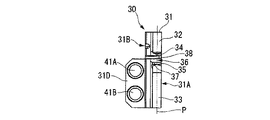
そして、さらに図13および図14に示すようにホルダ10の突出部15に穿設されたクランプネジ孔22にクランプネジ47をねじ込むことにより、このクランプネジ47の頭部がヘッド部材本体31の座ぐり部43の底面43Aに当接してクランプネジ47が上顎部32に係合し、次いで上顎部32が上記クランプネジ孔22の穿設された方向に押し付けられて、接続部39を支点として下顎部33側に撓むように弾性変形させられ、その押圧面34がインサート本体51を台座面35側に押圧して切削インサート50がクランプされて、本実施形態のインサート着脱式切削工具が構成される。
Further, as shown in FIGS. 13 and 14, the
しかるに、このようにクランプネジ47がねじ込まれるクランプネジ孔22の穿設された方向、すなわち上記仮想平面Pに対する離間方向に傾斜して上顎部32が押し付けられることにより、該上顎部32は上述のように下顎部33側に撓むとともに、この離間方向側すなわちホルダ10の他方の側面13B側に傾斜して倒れ込むようにも力を受けるが、上記構成のヘッド部材30およびインサート着脱式切削工具においては上顎部32の弾性変形の支点となる上記接続部39が、上記離間方向側に幅広となるように形成されているので、この離間方向側には変形し難くなる。
However, the
従って、上顎部32上面の座ぐり部43にクランプネジ47を係合させて、インサート取付座36に近い位置で上顎部32を押し付けたり、クランプネジ孔22をヘッド部材30の上記仮想平面Pに対して離間方向に傾斜させてホルダ10側に形成することにより、ネジ径の大きなクランプネジ47をねじ込むようにしたりしても、切削インサート50のクランプの際に上顎部32が傾斜してしまうのを防いで、その押圧面34を上記仮想平面Pに沿って真っ直ぐ台座面35側に接近させることができる。例えば、本実施形態のように押圧面34と台座面35が断面凸V字状、インサート本体51の下面と上面中央部とが断面凹V字状に形成されている場合には、これらのV字の二等分線が仮想平面P上で正確に一致した状態でインサート本体51をクランプすることができる。
Accordingly, the
このため、上記ヘッド部材30およびインサート着脱式切削工具によれば、こうして大径のクランプネジ47を用いたり、インサート取付座36に近い位置で上顎部32を押し付けたりすることによる大きなクランプ力を、インサート本体51に偏ることなく仮想平面Pに沿って均等に作用させることができ、クランプ時に切削インサート50が傾いてしまったり、クランプが不安定となったりするのを防ぐことができる。従って、溝入れ加工や突っ切り加工の際に切削インサート50にがたつきが生じたりするのも防いで、高精度の加工を円滑に行うことが可能となる。
Therefore, according to the
また、本実施形態のヘッド部材30では、このように上記離間方向に向けて幅広となる接続部39が、スリット38の後壁面38Bにおける該スリット38の延設方向に沿った断面において、この後壁面38Bとヘッド部材本体31の後端面31Fとが5°〜15°の範囲内の角度θで交差する方向に延びることにより形成されており、これにより、上述のような効果を確実に奏しつつも、上顎部32の下顎部33側への弾性変形自体が阻害されてしまうような事態を防ぐことができる。すなわち、この角度θが上記範囲より小さいと上顎部の傾斜を抑制することができない一方、上記範囲より大きいと接続部39を支点とした弾性変形自体が困難となるおそれが生じる。
Further, in the
なお、本実施形態では上述のようにヘッド部材本体31の後端面31Fが側面31A、31Bに垂直とされるとともに、スリット38後端の曲折部38Aの上記後壁面38Bが傾斜させられることにより、接続部39が上記離間方向側に向かうに従い延設方向に漸次幅広で厚肉となるようにされているが、これとは逆に後壁面38Bを側面31A、31Bに垂直として、後端面31Fを側面31A側から側面31B側に向かうに従い後端側に傾斜するようにしてもよく、また後壁面38Bと後端面31Fの双方を側面31A側から側面31B側に向かうに従い互いに離間するように傾斜させて接続部39を幅広となるように形成してもよい。
In the present embodiment, as described above, the
さらに、本実施形態では、このような後壁面38Bが形成されるスリット38が、インサート取付座36の後端から軸線Oに平行、すなわちインサート取付座36の押圧面34および台座面35に平行に延びた後、上顎部32側に延びるように曲折する曲折部38Aを有しており、これによりスリット38の延長線上にヘッド部材本体31を固定する固定ネジ42が挿通される挿通孔(第1挿通孔40B)が形成されていても、上顎部32の撓みの支点となる上記接続部39をよりインサート取付座36から離れた後端側に配置することができる。
Furthermore, in this embodiment, the
このため、上述のように上顎部32を仮想平面Pに沿って真っ直ぐ下顎部33側に撓ませるとともに、該仮想平面Pに対向する方向から見た場合のこの撓みによる押圧面34の傾斜の変化をもできるだけ小さくすることができる。従って、本実施形態によれば、上顎部32の離間方向への傾斜が防がれることとも相俟って、インサート本体51の上面中央部にこの押圧面34をより確実に密着させて押圧することが可能となり、切削インサート50を一層安定して強固にクランプすることが可能となる。また、こうしてスリット38の延長線上に挿通孔が形成されていても、これらが干渉するのを避けることができるので、ヘッド部材本体31の設計の自由度が増すとともにそのコンパクト化を図ることもできる。
Therefore, as described above, the
さらに本実施形態では、この曲折部38Aは、上記第1挿通孔40Bと同軸の円弧状をなすようにして、この第1挿通孔40Bの側面31A側の開口部と間隔をあけて形成されている。このため、本実施形態によれば、こうしてスリット38の後端部に曲折部38Aを形成しても、これら曲折部38Aと第1挿通孔40Bとの間の円弧状部分の肉厚を均一に確保することができ、第1挿通孔40Bに挿通された固定ネジ42の締め付け力などにより当該円弧状部分に破損が生じたりするのを防ぐことができる。
Further, in the present embodiment, the
なお、この曲折部38Aは、上記第1挿通孔40Bの周方向の長さが短すぎると接続部39の位置を後端側に配置することができず、かといってこの周方向に長すぎると第1挿通孔40Bとの間の円弧状部分も長くなりすぎて、如何に均一な肉厚が確保されても破損を生じるおそれがある。このため、上記曲折部38Aは、本実施形態のように第1挿通孔40Bの直上に接続部39が形成される程度の長さとされるのが望ましい。
If the circumferential length of the
一方、本実施形態のヘッド部材30においては、その側面31A、31Bに上述のような凹所44が形成されており、この凹所44が、周回りに連続した内壁面45と、この内壁面45にその全周に亙って連なる底面46とを有するものであるので、凹所44とヘッド部材本体31の上面や後端面31F、下端面31Cとの間には、該凹所44の底面46に対して屹立、突出するリブ状部が、凹所44を挟んで両側に少なくとも2つは形成されることになる。特に、本実施形態では側面31A、31Bに複数の凹所44A〜44Hが形成されているので、隣接する凹所44B〜44Eの内壁面45同士の間にもこのようなリブ状部が形成される。
On the other hand, in the
従って、上述の溝入れ・突っ切り加工の際に切削インサート50の先端側に向けられた切刃52からインサート本体51に振動が発生しても、この振動は、ヘッド部材30からホルダ10に伝播するときにこのような複数のリブ状部を介して分散させられることになって直接ホルダ10に伝播することがなくなるため、かかる振動が集中してホルダ10にビビリ振動等が発生したりするのを抑制することができる。また、この凹所44によってヘッド部材本体31の軽量化を図ることができるので、振動自体が減衰し易く、これによってもビビリ振動の発生を抑えることが可能となる。
Therefore, even if vibration is generated in the insert
このため、本実施形態によれば、溝入れ・突っ切り加工時の切刃52の突き出し量を大きくしても、このようなビビリ振動によって切削作業が妨げられたり加工精度の劣化を招いたりするのを防ぐことができ、より高精度で高品位の切削加工を安定的かつ円滑に行うことが可能となる。また、こうして凹所44が形成されることにより、ヘッド部材本体31の表面積が増大するので、切削時に切削インサート50に発生した切削熱もヘッド部材30を介して速やかに発散させることができ、たとえ乾式切削等においても切削インサート50に熱的損傷が生じたり切屑の溶着が発生したりするのを防ぐことも可能となる。
For this reason, according to the present embodiment, even if the protruding amount of the
その一方で、このような凹所44が形成されることによりヘッド部材本体31の肉厚が削がれても、本実施形態のヘッド部材30では凹所44が、第1、第2挿通孔40A〜40C、41A、41Bのようにヘッド部材本体31を貫通するものではなく、またインサート取付座36やスリット38、あるいは座ぐり部43のようにヘッド部材本体31の側面31A、31B間に位置する周端面(先端面や後端面31F、上面、下端面31C)に開口することもなく、上述のようなリブ状部が凹所44の周りに形成されるものであるので、ヘッド部材本体31の強度や剛性が著しく損なわれたりすることはない。また、特に上述のようにヘッド部材本体31にショットピーニングを施すことにより、一層確実にヘッド部材30の強度や剛性を向上させてさらに安定した切削を図ることができる。
On the other hand, even if the thickness of the head member
ただし、このようにリブ状部が形成されたりショットピーニングを施したりしても、凹所44の総容積があまりに大きくなりすぎると、ヘッド部材本体31の強度や剛性が低下することは避けられない。その一方で、この凹所44の総容積が小さすぎても、上述の振動防止や切削熱発散といった効果が不十分となるので、凹所44の総容積は、この凹所44が形成されていないヘッド部材本体31の体積の2%〜15%の範囲とされるのが望ましい。なお、本実施形態では凹所44が内壁面45に角度を持って交差する側面31A、31Bに平行な底面46を有しているが、これら内壁面45と底面46とが滑らかに連続する凹曲面をなすような、例えば凹球面状の凹所とされていてもよい。
However, even when the rib-like portion is formed or shot peened as described above, if the total volume of the
また、本実施形態では上述のようにヘッド部材本体31の一方の側面31Aと他方の側面31Bとの表裏の側面31A、31Bに凹所44A〜44Eと凹所44F〜44Hとがそれぞれ形成されており、これらの凹所44は側面31A、31Bに対向する方向から見たとき、すなわち側面31A、31Bのいずれかの側から見た投影視において互いに異なる形状とされている。このため、該凹所44A〜44Eと凹所44F〜44Hの周りに形成される上記リブ状部も互いに異なった形状となるため、振動をさらに確実に分散させることができる上、振動同士が互いに打ち消し合うようにすることもでき、ホルダ10への振動の伝播をより効果的に抑制することが可能となる。
In the present embodiment, as described above, the
さらに、本実施形態ではこれら表裏の側面31A、31Bに形成された凹所44A〜44Eと凹所44F〜44Hの該側面31A、31Bからの凹み深さが互いに異なるものとされており、これにより上記リブ状部の高さも表裏で異なるものとなるため、分散した振動を一層確実に打ち消し合わせたりすることができる。なお、本実施形態では一方の側面31Aの凹所44A〜44E同士と他方の側面31Bの凹所44F〜44H同士では、それぞれ凹み深さが等しくされているが、凹所44がヘッド部材本体31を貫通しなければ、各側面31A、31Bの少なくとも一方において凹み深さが互いに異なる凹所44が形成されていてもよい。
Further, in the present embodiment, the
10 ホルダ
16 装着部
22 クランプネジ孔
30 ヘッド部材
31 ヘッド部材本体
31A ヘッド部材本体31の一方の側面
31B ヘッド部材本体31の他方の側面
31F ヘッド部材本体31の後端面
32 上顎部
33 下顎部
34 押圧面
35 台座面
36 インサート取付座
38 スリット
38A 曲折部
38B 曲折部38Aの後壁面
39 接続部
40A〜40C 第1挿通孔
42 固定ネジ
43 座ぐり部
44(44A〜44H) 凹所
45 凹所44の内壁面
46 凹所44の底面
47 クランプネジ
50 切削インサート
51 インサート本体
52 切刃
O ホルダ10の軸線
P スリット38の延設方向に沿って押圧面34と台座面35とが対向する方向に延びる仮想平面
θ 後壁面38Bにおけるスリット38の延設方向に沿った断面において後壁面38Bと後端面31Fとがなす角度
DESCRIPTION OF
Claims (4)
Priority Applications (6)
| Application Number | Priority Date | Filing Date | Title |
|---|---|---|---|
| JP2007282118A JP5040591B2 (en) | 2007-10-30 | 2007-10-30 | Insert detachable cutting tool head member and insert detachable cutting tool |
| PCT/JP2008/069561 WO2009057599A1 (en) | 2007-10-30 | 2008-10-28 | Head member and tool main body of detachable insert cutting tool, and detachable insert cutting tool |
| KR1020107009098A KR101450372B1 (en) | 2007-10-30 | 2008-10-28 | Head member and tool main body of detachable insert cutting tool, and detachable insert cutting tool |
| US12/734,352 US8556549B2 (en) | 2007-10-30 | 2008-10-28 | Cutting tool with detachable insert, head member and tool body of the same |
| CN200880123356.7A CN101909793B (en) | 2007-10-30 | 2008-10-28 | Head member and tool main body of detachable insert cutting tool, and detachable insert cutting tool |
| EP08845496.2A EP2208563B1 (en) | 2007-10-30 | 2008-10-28 | Head member, tool body and cutting tool |
Applications Claiming Priority (1)
| Application Number | Priority Date | Filing Date | Title |
|---|---|---|---|
| JP2007282118A JP5040591B2 (en) | 2007-10-30 | 2007-10-30 | Insert detachable cutting tool head member and insert detachable cutting tool |
Publications (2)
| Publication Number | Publication Date |
|---|---|
| JP2009107071A JP2009107071A (en) | 2009-05-21 |
| JP5040591B2 true JP5040591B2 (en) | 2012-10-03 |
Family
ID=40590989
Family Applications (1)
| Application Number | Title | Priority Date | Filing Date |
|---|---|---|---|
| JP2007282118A Active JP5040591B2 (en) | 2007-10-30 | 2007-10-30 | Insert detachable cutting tool head member and insert detachable cutting tool |
Country Status (6)
| Country | Link |
|---|---|
| US (1) | US8556549B2 (en) |
| EP (1) | EP2208563B1 (en) |
| JP (1) | JP5040591B2 (en) |
| KR (1) | KR101450372B1 (en) |
| CN (1) | CN101909793B (en) |
| WO (1) | WO2009057599A1 (en) |
Families Citing this family (8)
| Publication number | Priority date | Publication date | Assignee | Title |
|---|---|---|---|---|
| JP5115148B2 (en) | 2007-10-30 | 2013-01-09 | 三菱マテリアル株式会社 | Insert detachable cutting tool head member and insert detachable cutting tool |
| JP5040591B2 (en) | 2007-10-30 | 2012-10-03 | 三菱マテリアル株式会社 | Insert detachable cutting tool head member and insert detachable cutting tool |
| DE102009030470B4 (en) * | 2009-06-24 | 2015-12-24 | Johne & Co. Präzisionswerkzeuge GmbH | Replaceable head holder system and tool head element |
| IL202027A (en) * | 2009-11-10 | 2015-03-31 | Iscar Ltd | Cutting tool assembly |
| CN102686343B (en) * | 2009-12-14 | 2015-02-18 | 京瓷株式会社 | Cutting tool holder, cutting tool, and cut workpiece manufacturing method using aforementioned cutting tool |
| US8911185B2 (en) | 2010-05-11 | 2014-12-16 | Mitsubishi Materials Corporation | Detachable insert type cutting tool |
| WO2013115284A1 (en) * | 2012-01-30 | 2013-08-08 | 京セラ株式会社 | Holder and cutting tool |
| US9211596B2 (en) * | 2013-08-26 | 2015-12-15 | Iscar, Ltd. | Detachable cutting tool segment with resilient clamping and cutting tool therefor |
Family Cites Families (25)
| Publication number | Priority date | Publication date | Assignee | Title |
|---|---|---|---|---|
| US3372451A (en) * | 1964-02-18 | 1968-03-12 | Cintride Ltd | Cutting tools for machines |
| US3376763A (en) | 1965-11-19 | 1968-04-09 | Halliburton Co | Boring tools |
| IL84171A (en) * | 1987-10-14 | 1990-09-17 | Iscar Ltd | Cutting insert and tool holder therefor |
| IL91574A (en) * | 1989-09-08 | 1992-02-16 | Iscar Ltd | Cutting tool system having an exchangeable adaptor |
| SE502242C2 (en) * | 1991-07-31 | 1995-09-25 | Sandvik Ab | Cut-off tool with mounting parts oriented in two perpendicular planes |
| IL111370A (en) * | 1994-10-23 | 1998-08-16 | Iscar Ltd | Cutting tool assembly having an exchangeable adaptor |
| JPH08215904A (en) | 1995-02-10 | 1996-08-27 | Sumitomo Electric Ind Ltd | Cutting-off tool |
| IL115544A (en) * | 1995-10-06 | 1998-12-06 | Iscar Ltd | Cutting tool assembly having an exchangeable adaptor |
| US5873682A (en) | 1997-04-14 | 1999-02-23 | Koyo Corporation Of Usa | Pivoting tool holder |
| CH692449A5 (en) | 1997-11-13 | 2002-06-28 | Syntronic Ag | Tool holder, for a machine tool, has a holder section positioned and centered at an exchangeable plate carrier, locked by a bolt in an easily adapted and low cost structure |
| US6270293B2 (en) | 1998-12-22 | 2001-08-07 | Kennametal Pc Inc. | Toolholder assembly |
| US6186704B1 (en) | 1999-03-04 | 2001-02-13 | Kennametal Inc. | Toolholder with detachable blade |
| JP4035927B2 (en) * | 1999-08-23 | 2008-01-23 | 三菱マテリアル株式会社 | Claw mechanism for throw-away tip |
| SE521183C2 (en) * | 2001-03-15 | 2003-10-07 | Sandvik Ab | Cutting holder with means for adjusting the cutting position holder |
| DE10153646A1 (en) * | 2001-10-31 | 2003-05-22 | Horn P Hartmetall Werkzeugfab | Tool holder for reversible cutting plates has contact bearing face divided by integral indentation into area parts forming between same a seat for holding protruding fitment of base holder with keyed engagement |
| SE523405C2 (en) * | 2001-12-21 | 2004-04-13 | Seco Tools Ab | Tool for cutting machining with a rounded hard element in a support surface in the holder. |
| SE525462C2 (en) * | 2002-06-18 | 2005-02-22 | Sandvik Ab | Tool head for chip separating metal machining tool with clamping screw which is inserted into a nut roll |
| JP2004202631A (en) | 2002-12-25 | 2004-07-22 | Daishowa Seiki Co Ltd | Tool holder for lathe |
| SE526767C2 (en) | 2003-10-16 | 2005-11-01 | Sandvik Intellectual Property | Cutting tool with add-on body with serration surface and procedure for manufacturing cutting tools |
| CN1757471A (en) * | 2004-10-08 | 2006-04-12 | 上海维科精密模塑有限公司 | Disassembled combination tool |
| DE102005038828A1 (en) | 2005-08-17 | 2007-02-22 | Kennametal Inc. | Blade holder for the clamping attachment of a cutting insert |
| JP4867661B2 (en) * | 2006-03-02 | 2012-02-01 | 三菱マテリアル株式会社 | Insert detachable cutting tool |
| JP5028883B2 (en) * | 2006-06-30 | 2012-09-19 | 三菱マテリアル株式会社 | Insert detachable cutting tool |
| JP5040591B2 (en) | 2007-10-30 | 2012-10-03 | 三菱マテリアル株式会社 | Insert detachable cutting tool head member and insert detachable cutting tool |
| JP5309894B2 (en) | 2008-10-29 | 2013-10-09 | 三菱マテリアル株式会社 | Insert detachable cutting tool |
-
2007
- 2007-10-30 JP JP2007282118A patent/JP5040591B2/en active Active
-
2008
- 2008-10-28 CN CN200880123356.7A patent/CN101909793B/en active Active
- 2008-10-28 US US12/734,352 patent/US8556549B2/en active Active
- 2008-10-28 EP EP08845496.2A patent/EP2208563B1/en active Active
- 2008-10-28 KR KR1020107009098A patent/KR101450372B1/en active IP Right Grant
- 2008-10-28 WO PCT/JP2008/069561 patent/WO2009057599A1/en active Application Filing
Also Published As
| Publication number | Publication date |
|---|---|
| WO2009057599A1 (en) | 2009-05-07 |
| KR101450372B1 (en) | 2014-10-14 |
| EP2208563A4 (en) | 2011-04-27 |
| CN101909793B (en) | 2012-06-20 |
| JP2009107071A (en) | 2009-05-21 |
| US8556549B2 (en) | 2013-10-15 |
| CN101909793A (en) | 2010-12-08 |
| US20100266352A1 (en) | 2010-10-21 |
| EP2208563B1 (en) | 2014-10-08 |
| EP2208563A1 (en) | 2010-07-21 |
| KR20100075962A (en) | 2010-07-05 |
Similar Documents
| Publication | Publication Date | Title |
|---|---|---|
| JP5115148B2 (en) | Insert detachable cutting tool head member and insert detachable cutting tool | |
| JP5040591B2 (en) | Insert detachable cutting tool head member and insert detachable cutting tool | |
| JP4717063B2 (en) | Cutting tools | |
| KR101323558B1 (en) | Insert with a mounting hole and toolholder including a cutting insert | |
| CN108602130B (en) | Face grooving tool body for metal cutting | |
| JP2012524665A (en) | Cutting tool and cutting insert therefor | |
| KR20110081218A (en) | Tool for cutting hole inner surface and method of cutting hole inner surface | |
| EP2498937B1 (en) | Cutting tool assembly | |
| JPWO2016186113A1 (en) | Cutting inserts, tool bodies and cutting tools | |
| EP1263543A1 (en) | Cutting tool assembly | |
| JP5071048B2 (en) | Insert detachable cutting tool head member and insert detachable cutting tool | |
| JP5678795B2 (en) | Insert detachable cutting tool | |
| JP2013244583A (en) | Replaceable turning head and head replacement type turning tool | |
| KR100595409B1 (en) | A cutting tool with round insert mounting thereof | |
| JP2011240462A (en) | Head member of insert detachable cutting tool, and the insert detachable cutting tool | |
| JP5526743B2 (en) | Insert detachable cutting tool head member and insert detachable cutting tool | |
| JP2012035375A (en) | Head member of cutting edge replaceable grooving tool, head member body, and cutting edge replaceable grooving tool | |
| JP2020116708A (en) | Clamp mechanism of cutting insert | |
| JP4424209B2 (en) | Cutting insert clamping mechanism | |
| JP2018065195A (en) | Tip displacement type cutting tool |
Legal Events
| Date | Code | Title | Description |
|---|---|---|---|
| A621 | Written request for application examination |
Free format text: JAPANESE INTERMEDIATE CODE: A621 Effective date: 20100929 |
|
| TRDD | Decision of grant or rejection written | ||
| A01 | Written decision to grant a patent or to grant a registration (utility model) |
Free format text: JAPANESE INTERMEDIATE CODE: A01 Effective date: 20120612 |
|
| A01 | Written decision to grant a patent or to grant a registration (utility model) |
Free format text: JAPANESE INTERMEDIATE CODE: A01 |
|
| A61 | First payment of annual fees (during grant procedure) |
Free format text: JAPANESE INTERMEDIATE CODE: A61 Effective date: 20120625 |
|
| R150 | Certificate of patent or registration of utility model |
Ref document number: 5040591 Country of ref document: JP Free format text: JAPANESE INTERMEDIATE CODE: R150 Free format text: JAPANESE INTERMEDIATE CODE: R150 |
|
| FPAY | Renewal fee payment (event date is renewal date of database) |
Free format text: PAYMENT UNTIL: 20150720 Year of fee payment: 3 |