JP2014511467A - Friction clutch plate with damping spring - Google Patents
Friction clutch plate with damping spring Download PDFInfo
- Publication number
- JP2014511467A JP2014511467A JP2013556934A JP2013556934A JP2014511467A JP 2014511467 A JP2014511467 A JP 2014511467A JP 2013556934 A JP2013556934 A JP 2013556934A JP 2013556934 A JP2013556934 A JP 2013556934A JP 2014511467 A JP2014511467 A JP 2014511467A
- Authority
- JP
- Japan
- Prior art keywords
- spring
- hub
- clutch plate
- drive
- plate
- Prior art date
- Legal status (The legal status is an assumption and is not a legal conclusion. Google has not performed a legal analysis and makes no representation as to the accuracy of the status listed.)
- Pending
Links
Images


Classifications
-
- F—MECHANICAL ENGINEERING; LIGHTING; HEATING; WEAPONS; BLASTING
- F16—ENGINEERING ELEMENTS AND UNITS; GENERAL MEASURES FOR PRODUCING AND MAINTAINING EFFECTIVE FUNCTIONING OF MACHINES OR INSTALLATIONS; THERMAL INSULATION IN GENERAL
- F16D—COUPLINGS FOR TRANSMITTING ROTATION; CLUTCHES; BRAKES
- F16D13/00—Friction clutches
- F16D13/58—Details
- F16D13/60—Clutching elements
- F16D13/64—Clutch-plates; Clutch-lamellae
- F16D13/68—Attachments of plates or lamellae to their supports
- F16D13/686—Attachments of plates or lamellae to their supports with one or more intermediate members made of rubber or like material transmitting torque from the linings to the hub
-
- F—MECHANICAL ENGINEERING; LIGHTING; HEATING; WEAPONS; BLASTING
- F16—ENGINEERING ELEMENTS AND UNITS; GENERAL MEASURES FOR PRODUCING AND MAINTAINING EFFECTIVE FUNCTIONING OF MACHINES OR INSTALLATIONS; THERMAL INSULATION IN GENERAL
- F16F—SPRINGS; SHOCK-ABSORBERS; MEANS FOR DAMPING VIBRATION
- F16F15/00—Suppression of vibrations in systems; Means or arrangements for avoiding or reducing out-of-balance forces, e.g. due to motion
- F16F15/10—Suppression of vibrations in rotating systems by making use of members moving with the system
- F16F15/12—Suppression of vibrations in rotating systems by making use of members moving with the system using elastic members or friction-damping members, e.g. between a rotating shaft and a gyratory mass mounted thereon
- F16F15/121—Suppression of vibrations in rotating systems by making use of members moving with the system using elastic members or friction-damping members, e.g. between a rotating shaft and a gyratory mass mounted thereon using springs as elastic members, e.g. metallic springs
- F16F15/123—Wound springs
- F16F15/12306—Radially mounted springs
-
- F—MECHANICAL ENGINEERING; LIGHTING; HEATING; WEAPONS; BLASTING
- F16—ENGINEERING ELEMENTS AND UNITS; GENERAL MEASURES FOR PRODUCING AND MAINTAINING EFFECTIVE FUNCTIONING OF MACHINES OR INSTALLATIONS; THERMAL INSULATION IN GENERAL
- F16F—SPRINGS; SHOCK-ABSORBERS; MEANS FOR DAMPING VIBRATION
- F16F15/00—Suppression of vibrations in systems; Means or arrangements for avoiding or reducing out-of-balance forces, e.g. due to motion
- F16F15/10—Suppression of vibrations in rotating systems by making use of members moving with the system
- F16F15/12—Suppression of vibrations in rotating systems by making use of members moving with the system using elastic members or friction-damping members, e.g. between a rotating shaft and a gyratory mass mounted thereon
- F16F15/121—Suppression of vibrations in rotating systems by making use of members moving with the system using elastic members or friction-damping members, e.g. between a rotating shaft and a gyratory mass mounted thereon using springs as elastic members, e.g. metallic springs
- F16F15/123—Wound springs
-
- F—MECHANICAL ENGINEERING; LIGHTING; HEATING; WEAPONS; BLASTING
- F16—ENGINEERING ELEMENTS AND UNITS; GENERAL MEASURES FOR PRODUCING AND MAINTAINING EFFECTIVE FUNCTIONING OF MACHINES OR INSTALLATIONS; THERMAL INSULATION IN GENERAL
- F16F—SPRINGS; SHOCK-ABSORBERS; MEANS FOR DAMPING VIBRATION
- F16F15/00—Suppression of vibrations in systems; Means or arrangements for avoiding or reducing out-of-balance forces, e.g. due to motion
- F16F15/10—Suppression of vibrations in rotating systems by making use of members moving with the system
- F16F15/12—Suppression of vibrations in rotating systems by making use of members moving with the system using elastic members or friction-damping members, e.g. between a rotating shaft and a gyratory mass mounted thereon
- F16F15/131—Suppression of vibrations in rotating systems by making use of members moving with the system using elastic members or friction-damping members, e.g. between a rotating shaft and a gyratory mass mounted thereon the rotating system comprising two or more gyratory masses
- F16F15/133—Suppression of vibrations in rotating systems by making use of members moving with the system using elastic members or friction-damping members, e.g. between a rotating shaft and a gyratory mass mounted thereon the rotating system comprising two or more gyratory masses using springs as elastic members, e.g. metallic springs
- F16F15/134—Wound springs
- F16F15/13469—Combinations of dampers, e.g. with multiple plates, multiple spring sets, i.e. complex configurations
- F16F15/13476—Combinations of dampers, e.g. with multiple plates, multiple spring sets, i.e. complex configurations resulting in a staged spring characteristic, e.g. with multiple intermediate plates
- F16F15/13484—Combinations of dampers, e.g. with multiple plates, multiple spring sets, i.e. complex configurations resulting in a staged spring characteristic, e.g. with multiple intermediate plates acting on multiple sets of springs
-
- F—MECHANICAL ENGINEERING; LIGHTING; HEATING; WEAPONS; BLASTING
- F16—ENGINEERING ELEMENTS AND UNITS; GENERAL MEASURES FOR PRODUCING AND MAINTAINING EFFECTIVE FUNCTIONING OF MACHINES OR INSTALLATIONS; THERMAL INSULATION IN GENERAL
- F16D—COUPLINGS FOR TRANSMITTING ROTATION; CLUTCHES; BRAKES
- F16D13/00—Friction clutches
- F16D13/58—Details
- F16D13/60—Clutching elements
- F16D13/64—Clutch-plates; Clutch-lamellae
-
- F—MECHANICAL ENGINEERING; LIGHTING; HEATING; WEAPONS; BLASTING
- F16—ENGINEERING ELEMENTS AND UNITS; GENERAL MEASURES FOR PRODUCING AND MAINTAINING EFFECTIVE FUNCTIONING OF MACHINES OR INSTALLATIONS; THERMAL INSULATION IN GENERAL
- F16D—COUPLINGS FOR TRANSMITTING ROTATION; CLUTCHES; BRAKES
- F16D2300/00—Special features for couplings or clutches
- F16D2300/22—Vibration damping
Abstract
クラッチプレート(100)が環状周囲部を有するプレート組立体(111)を有し、環状周囲部に両方向に面するように摩擦材料の組立体(114、115)が付着される。ハブ(120)が出力シャフトに接続されるために設けられ、ハブフランジ(132)がプレート組立体により回転するように駆動可能である。ハブ(120)はハブフランジ(132)により回転するように駆動可能である。ハブ(120)およびハブフランジ(132)は、角度方向において所定の範囲内で互いに相対的に変位可能であり、また、ハブの回転軸を基準として径方向に延在しかつハブ(120)とハブフランジ(132)との間での相対的な角度変位に逆らうように付勢荷重を適用する引張ばね(125)によって一体に結合される。別の一実施形態が開示され、ここでは、プレート組立体(111)およびハブフランジ(132)が角度方向において所定の範囲内で互いに相対的に変位可能であり、また、一定の曲率半径を有しかつハブ(120)の周りに同心状に設置される少なくとも2つの湾曲する駆動ばね(150、151)によって一体に結合される。
【選択図】図5The clutch plate (100) has a plate assembly (111) having an annular periphery, and an assembly of friction material (114, 115) is attached to the annular periphery so as to face both directions. A hub (120) is provided for connection to the output shaft, and the hub flange (132) can be driven to rotate by the plate assembly. The hub (120) can be driven to rotate by a hub flange (132). The hub (120) and the hub flange (132) are relatively displaceable relative to each other within a predetermined range in the angular direction, and extend radially with respect to the rotation axis of the hub and They are joined together by a tension spring (125) that applies a biasing load against the relative angular displacement with the hub flange (132). Another embodiment is disclosed in which the plate assembly (111) and the hub flange (132) are displaceable relative to each other within a predetermined range in the angular direction and have a constant radius of curvature. And are joined together by at least two curved drive springs (150, 151) installed concentrically around the hub (120).
[Selection] Figure 5
Description
本発明は、主に自動車部門において使用される、手動変速の車およびトラックのための摩擦クラッチ組立体に関する。しかし、本発明にはより広範囲の用途がある。本発明は、詳細には、クラッチ組立体のクラッチプレートを対象とする。自動車部門に関連させて本発明を説明することが好都合であるが、本発明が自動車部門のみで使用されることに限定されないことを認識されたい。 The present invention relates to a friction clutch assembly for manually geared cars and trucks, mainly used in the automotive sector. However, the present invention has a wider range of applications. The present invention is specifically directed to a clutch plate of a clutch assembly. While it is convenient to describe the present invention in the context of the automotive sector, it should be appreciated that the present invention is not limited to being used only in the automotive sector.
手動変速機を有する車または別の自動車の摩擦クラッチ組立体すなわち「クラッチ」は、一般に、エンジンと駆動列との間に位置する。摩擦クラッチ組立体は、通常、3つの隣接する環状プレートを有し、これらには、クランクシャフトによって回転可能に駆動されるフライホイールと、クラッチプレート(他には被駆動プレートとしても知られる)と、フライホイールと圧力プレートとの間でクラッチプレートをクランプするためにクラッチプレートおよびフライホイールの方に向かうように1つまたは複数のばねなどのエネルギー蓄積デバイスによって付勢される圧力プレートとが、含まれる。 The friction clutch assembly or “clutch” of a vehicle having a manual transmission or another vehicle is generally located between the engine and the drive train. Friction clutch assemblies typically have three adjacent annular plates that include a flywheel that is rotatably driven by a crankshaft, and a clutch plate (also known as a driven plate). A pressure plate biased by an energy storage device such as one or more springs toward the clutch plate and the flywheel to clamp the clutch plate between the flywheel and the pressure plate It is.
クラッチプレートの結合フェイス(face)がフライホイールおよび圧力プレートの隣接する回転結合フェイスに摩擦係合されることにより、クラッチプレートがエンジンによって生成される動力を駆動列の残りの部分に伝達することが可能となる。しかし、石油内燃エンジンまたはディーゼル内燃エンジンの不規則な衝撃を散逸させるために駆動ライン内で何らかの減衰が行われない場合、これらの衝撃により、ギアボックス内の噛合されるギア間のバックラッシを原因として、望ましくない駆動ラインノイズ(driveline noise)が発生する。減衰されないいかなるエンジン振動もギアボックス内にノイズを発生させるが、駆動ラインノイズは、車両のギアがニュートラル状態でありかつクラッチが係合されているときに特に顕著となる。本業界ではこのノイズは「ギアロールオーバーノイズ(gear rollover noise)」として知られる。 The clutch plate coupling face is frictionally engaged with the adjacent rotary coupling face of the flywheel and pressure plate so that the clutch plate can transmit the power generated by the engine to the rest of the drive train. It becomes possible. However, if any damping is not done in the drive line to dissipate the irregular impacts of oil internal combustion engines or diesel internal combustion engines, these impacts cause backlash between the meshed gears in the gearbox. Undesirable drive line noise is generated. Any engine vibration that is not damped will generate noise in the gearbox, but driveline noise is particularly noticeable when the vehicle gear is in a neutral state and the clutch is engaged. In the industry, this noise is known as “gear rollover noise”.
車両がニュートラル状態でありかつクラッチが係合されているときに、ギアボックスにエンジンの衝撃が伝達されるのを防止するために、通常はコイルばねまたは別の減衰手段の形態で減衰が行われるクラッチプレートが使用され得る。通常のクラッチ組立体が、既に、エンジンからギアボックスへ動力を伝達するために駆動ばねとして知られる減衰ばねを採用しているのに対して、上記の目的のために必要となる減衰は、ギアロールオーバーノイズに対処するために必要となる減衰とは異なる。したがって、通常は別個の減衰システムが必要となる。この別個の減衰システムは、ギアロールオーバーノイズを減衰するために例えば0.1Nm/度から0.6Nm/度といったような1Nm/度未満の小さいトルクで広い角度範囲で変位されることが可能でなければならない。これは、通常は20Nm/度から80Nm/度といったような20Nm/度を超えるような、車両の最大トルク容量の通常は120%である高いトルク容量を必要とする駆動ばねとは異なる。 Damping is usually done in the form of a coil spring or other damping means to prevent engine shocks from being transmitted to the gearbox when the vehicle is in the neutral state and the clutch is engaged. A clutch plate may be used. Whereas a typical clutch assembly already employs a damping spring known as a drive spring to transmit power from the engine to the gearbox, the damping required for the above purpose is the gear. This is different from the attenuation required to deal with rollover noise. Therefore, usually a separate damping system is required. This separate damping system can be displaced over a wide angular range with a small torque of less than 1 Nm / degree, for example 0.1 Nm / degree to 0.6 Nm / degree to attenuate gear rollover noise. There must be. This is different from drive springs that require a high torque capacity, typically 120% of the vehicle's maximum torque capacity, such as typically exceeding 20 Nm / degree, such as 20 Nm / degree to 80 Nm / degree.
通常のクラッチプレートは、エンジンの回転をギアボックスまたは変速機に伝達するためのスプラインシャフトを受け入れるためのスプラインハブを有する。このスプラインハブは、ハブとハブフランジとの間の制限された角度で変位されるのを可能にするような構成を介してフランジに接続され得る。ハブとハブシャフトとの間でのばねによる減衰がギアロールオーバーノイズを減衰するのに使用され得る。 A typical clutch plate has a spline hub for receiving a spline shaft for transmitting engine rotation to a gearbox or transmission. The spline hub can be connected to the flange via a configuration that allows it to be displaced at a limited angle between the hub and the hub flange. Spring damping between the hub and hub shaft can be used to damp gear rollover noise.
上記の種類のような構成では、ハブフランジは、一体に固定される主プレートと副プレートとの間に挟まれ得、それにより、主プレートの円周縁部に対して固定される摩擦材料を介して主プレートがエンジンのフライホイールに係合される状態へと移行されるときにハブフランジが回転するように駆動される。この主プレートと副プレートとの組立体(以降、「プレート組立体」)およびハブフランジは駆動ばねによって接続され、したがって、それらの間での角度変位は制限される。このような事例の角度範囲は、変速機がニュートラル状態にありかつクラッチが係合されているときのギアロールオーバーノイズを減衰するためというよりはむしろ、車両が駆動モードにあるときのねじり振動を減衰するために設けられるものである。 In a configuration such as the type described above, the hub flange can be sandwiched between a main plate and a sub-plate that are fixed together, thereby interposing a friction material that is fixed to the circumferential edge of the main plate. The hub flange is driven to rotate when the main plate is shifted to a state where it is engaged with the flywheel of the engine. The main plate and sub-plate assembly (hereinafter “plate assembly”) and the hub flange are connected by a drive spring, thus limiting the angular displacement between them. The angular range in such cases is torsional vibration when the vehicle is in drive mode, rather than to attenuate gear rollover noise when the transmission is in neutral and the clutch is engaged. It is provided to attenuate.
ギアロールオーバーノイズを減衰するための減衰システムがハブとハブフランジとの間に設けられる場合、一部の従来技術の構成では、円周方向の圧縮ばねによって減衰が行われる。しかし、これらのシステムでは、ハブとハブフランジとの間での可能な角度変位が小さい範囲に制限される。通常、ギアロールオーバーノイズを排除するのに必要となる角度変位は非常に広いが、従来技術のシステムの円周方向の圧縮ばねを収容するのに利用可能である空間は、ギアロールオーバーノイズを完全に減衰するかまたは大幅に減衰するのに必要となる角度変位を得ることに関して必ずしも十分ではない。ハブの中心から最大の径方向距離のところに圧縮ばねを配置することにより、最大の角度変位が得られる。しかし、圧縮ばねがハブから離れて配置されると、等しい角度変位を得るのに必要となるばねの長さが増大する。したがって、ハブフランジとプレート組立体との間の駆動ばねなどの、クラッチの別の構成要素により、さらには、摩擦材料の内径により、ばねをハブから離して配置し得る距離が制限されることから、空間に関する問題が生じる可能性がある。したがって、通常、達成され得る最大角度変位を得ることと、使用され得るばねの長さを得ることとの間で妥協が存在する。 When a damping system for damping gear rollover noise is provided between the hub and the hub flange, in some prior art configurations, the damping is provided by a circumferential compression spring. However, these systems limit the possible angular displacement between the hub and the hub flange to a small range. Typically, the angular displacement required to eliminate gear rollover noise is very wide, but the space available to accommodate the circumferential compression springs of prior art systems reduces gear rollover noise. It is not always sufficient to obtain the angular displacement required to fully dampen or to dampen significantly. By placing the compression spring at the maximum radial distance from the center of the hub, the maximum angular displacement is obtained. However, when the compression spring is placed away from the hub, the length of the spring required to obtain equal angular displacement increases. Thus, other components of the clutch, such as the drive spring between the hub flange and the plate assembly, and the inner diameter of the friction material limit the distance that the spring can be placed away from the hub. , Space problems can arise. Thus, there is usually a compromise between obtaining the maximum angular displacement that can be achieved and obtaining the spring length that can be used.
米国特許第6,029,793号明細書が、各々が円周方向に配置される複数のコイルばねを備える減衰構成を有するクラッチ組立体を開示している。ねじり振動が発生すると、フライホイールによって駆動される入力回転部材と伝動シャフトを駆動させる出力回転部材との間の相対運動を介して、種々のばねが圧縮される。4つの異なるばねセットが設けられる。米国特許第6,029,793号明細書の図2を参照すると、種々のばねの位置が密集しており、したがって角度変位が制限されている。さらに、構成の複雑さにより、製造および組み立てのコストが増大する。 U.S. Pat. No. 6,029,793 discloses a clutch assembly having a damping configuration with a plurality of coil springs each disposed circumferentially. When torsional vibrations occur, the various springs are compressed through relative motion between the input rotating member driven by the flywheel and the output rotating member driving the transmission shaft. Four different spring sets are provided. Referring to FIG. 2 of US Pat. No. 6,029,793, the location of the various springs is dense and therefore the angular displacement is limited. Furthermore, the complexity of the construction increases the cost of manufacturing and assembly.
ギアロールオーバーノイズを減衰するための減衰システムが許容されるレベルまでノイズを減衰するのに十分ではない場合、しばしば、この解決策としてデュアルマスフライホイールが採用される。この解決策は、しばしば、ギアロールオーバーノイズを解消するくらいの十分な減衰を行うことができるが、このようなフライホイールは非常に高価であり、したがって好適ではない。 Often a dual mass flywheel is employed as a solution if the damping system to attenuate gear rollover noise is not sufficient to attenuate the noise to an acceptable level. While this solution can often provide sufficient attenuation to eliminate gear rollover noise, such a flywheel is very expensive and therefore not preferred.
したがって、本発明は、ギアロールオーバーノイズに対処するための解決策を提供することの必要性を認識する。
駆動ばねに関して、従来技術の摩擦クラッチ組立体は、通常、エンジンのフライホイールに係合されるクラッチ組立体のプレート組立体(主プレートおよび副プレートの組み合わせとして上で定義される)とクラッチ組立体のハブフランジとの間で動作する直線状のコイル圧縮ばねを採用する。一部の別のクラッチ組立体では、直線状のゴムシリンダが採用される。
Thus, the present invention recognizes the need to provide a solution for dealing with gear rollover noise.
With respect to drive springs, prior art friction clutch assemblies typically include a clutch assembly plate assembly (defined above as a combination of a main plate and a secondary plate) and a clutch assembly that are engaged with an engine flywheel. Adopting a linear coil compression spring that operates between the hub flange. Some other clutch assemblies employ a linear rubber cylinder.
直線状のコイル圧縮ばねを使用することが好適であるのは、その製造が容易でありしたがって安価であることを理由とする。さらに、従来のクラッチ組立体のクラッチプレートは(上述したように)角度変位が小さく、またしたがって、駆動ばねに生成されるばねの力は、わずかな角度をもってばねに作用するが、実質的にばねの軸に沿う向きとなる。ばねの力が実質的にばねの軸に沿ってばねに作用する場合、本目的のためには直線状の圧縮ばねで十分である。 The use of a linear coil compression spring is preferred because it is easy to manufacture and therefore inexpensive. Furthermore, the clutch plate of the conventional clutch assembly has a small angular displacement (as described above), and therefore the spring force generated on the drive spring acts on the spring with a slight angle, but substantially the spring The direction is along the axis. If the spring force acts on the spring substantially along the axis of the spring, a linear compression spring is sufficient for this purpose.
上述した従来のクラッチプレートでは、駆動ばねも、直線状を維持するためにその長手方向に沿うガイドを必要とすることなく動作することができる。これにより得られる利益は、ばねがクラッチ組立体の別の構成要素上で不必要に擦れることがないことであり、仮に不必要に擦れる場合は摩耗して熱を発生させ、そのいずれもクラッチプレートの寿命にとって不利となる可能性がある。 In the conventional clutch plate described above, the drive spring can also operate without the need for a guide along its longitudinal direction in order to maintain a linear shape. The benefit gained from this is that the spring does not rub unnecessarily on another component of the clutch assembly, and if it rubs unnecessarily, it wears and generates heat, both of which are clutch plates. Can be detrimental to the lifetime of
小さい角度変位を有する従来のクラッチプレートで直線状のコイル圧縮ばねを使用することのこの利益は、クラッチプレートが広範囲の角度変位を有する場合には得られない。このような形態のクラッチプレートでは、駆動ばねは変位の広範囲の角度に跨がって延在するのに十分な長さであることが必要であるが、駆動ばねはさらに、クラッチプレートを介して伝達されるエンジンのトルクに適合するのに十分な強度を維持する必要がある。このような形態のクラッチプレート内の駆動ばねは小さい角度変位を有するクラッチプレートの駆動ばねより長いことが必要であることから、より短い形態のばねが通常嵌合されるところのクラッチプレートの中央における利用可能な空間内により長いばねを嵌合することは通常は不可能である。 This benefit of using a linear coil compression spring with a conventional clutch plate having a small angular displacement is not obtained when the clutch plate has a wide range of angular displacements. In such a form of clutch plate, the drive spring needs to be long enough to extend over a wide range of angles of displacement, but the drive spring further passes through the clutch plate. Sufficient strength must be maintained to match the transmitted engine torque. Since the drive spring in such a form of clutch plate needs to be longer than the drive spring of the clutch plate having a small angular displacement, it is at the center of the clutch plate where the shorter form spring is normally fitted. It is usually not possible to fit a longer spring in the available space.
さらに、変位の広範囲の角度を有するクラッチプレート内の駆動ばねとしてより長い直線状のコイル圧縮ばねが使用される場合、ばねが圧縮されると、ばねの力がばねの軸に沿って作用しなくなり、したがって、ばねの通常の圧縮強さが得られなくなる。実際にはより長いばねは、クラッチプレートの副プレートおよび主プレートに対して作用するハブフランジによって台形状にされる。 Furthermore, if a longer linear coil compression spring is used as the drive spring in the clutch plate with a wide range of displacement angles, the spring force will not act along the spring axis when the spring is compressed. Therefore, the normal compressive strength of the spring cannot be obtained. In practice, the longer spring is trapped by the hub flange acting against the clutch plate sub-plate and the main plate.
したがって、本出願者は、変位の広範囲の角度を有するクラッチプレートにおいて代替の駆動ばね構成を提供することの必要性を認識している。 Accordingly, the Applicant has recognized the need to provide an alternative drive spring configuration in a clutch plate having a wide range of displacement angles.
本発明はクラッチプレートを提供し、このクラッチプレートは:
環状周囲部を有するプレート組立体であって、この環状周囲部に、互いに対向する方向の各々に面するように摩擦材料の組立体が取り付けられる、プレート組立体と、
出力シャフトに接続されるハブと、
プレート組立体によって回転するように駆動可能であるハブフランジと
を有し、
ハブがハブフランジにより回転するように駆動可能であり、
ハブおよびハブフランジが、角度方向において所定の範囲内で互いに対して変位可能であり、ハブの回転軸に対して径方向に延在しかつハブとハブフランジとの間での相対的な角度変位に対して付勢荷重を加える引張ばねによって、共に結合される。
The present invention provides a clutch plate, which is:
A plate assembly having an annular perimeter, the assembly of friction material being attached to the annular perimeter so as to face each other in opposite directions; and
A hub connected to the output shaft;
A hub flange that is drivable for rotation by the plate assembly;
The hub can be driven to rotate by the hub flange,
The hub and the hub flange are displaceable relative to each other within a predetermined range in the angular direction, extend radially with respect to the axis of rotation of the hub and the relative angular displacement between the hub and the hub flange They are coupled together by a tension spring that applies a biasing load to the.
この径方向の引張ばねは、ハブおよびハブフランジが互いに対して変位されるときにすなわち互いに対して回転するときに、振動する。したがって、この径方向の引張ばねはギアロールオーバーノイズの原因となる振動を減衰し、ここでは有利には、径方向に作用するばねを使用することにより、ハブとハブフランジとの間で許容され得る角度変位が従来技術の円周方向のばねを用いる場合より大幅に大きくなる。 This radial tension spring vibrates when the hub and hub flange are displaced relative to each other, ie, rotate relative to each other. Therefore, this radial tension spring damps vibrations that cause gear rollover noise, and here is advantageously allowed between the hub and hub flange by using a radially acting spring. The resulting angular displacement is significantly greater than with prior art circumferential springs.
したがって、上記の種類のクラッチ組立体では、径方向のねじりばねによって提供され得る角度変位が、円周方向の圧縮ばねを採用する既知の構成の場合より広範囲となり、可能性として大幅により広範囲となる。さらに、上記の種類のクラッチ組立体では、径方向の引張ばねが円周方向ではなく径方向に延在することにより、従来技術の円周方向のばねの場合よりクラッチプレート内でより容易にばねを収容することが可能となる。 Thus, in the type of clutch assembly described above, the angular displacement that can be provided by a radial torsion spring is more extensive than the known configuration employing a circumferential compression spring, and potentially much wider. . Further, in the type of clutch assembly described above, the radial tension springs extend in the radial direction, rather than in the circumferential direction, thereby making it easier to spring in the clutch plate than in the case of prior art circumferential springs. Can be accommodated.
円周方向に延在するばねによって得られる角度変位は最大で14度程度である。これに対して、径方向の引張ばねでは、角度変位は最大で60度程度まで可能となる。
単一の径方向の引張ばねが採用されてよいが、一部の構成では、2つ以上のばねが採用される。一対のばねが採用される構成では、ばねは任意適切な向きに配置されよいが、最も高い可能性では互いに径方向反対側に配置される。別の構成では、3つまたは4つのばねが採用される。これらの構成では、ばねはハブの周りで等間隔に離間されてよく、あるいは別の任意適切な向きに配置されてよい。実際には、任意の数のばねすなわち4つを超えるばねが採用されてもよく、この数は奇数であっても偶数であってもよい。
The angular displacement obtained by the spring extending in the circumferential direction is about 14 degrees at the maximum. On the other hand, with a radial tension spring, the angular displacement can be up to about 60 degrees.
Although a single radial tension spring may be employed, in some configurations, two or more springs are employed. In configurations where a pair of springs are employed, the springs may be arranged in any suitable orientation, but most likely are arranged radially opposite each other. In other configurations, three or four springs are employed. In these configurations, the springs may be evenly spaced around the hub or may be placed in any other suitable orientation. In practice, any number of springs, i.e., more than four, may be employed, and this number may be odd or even.
径方向の引張ばねの長さは、ばねが嵌合されるクラッチプレートに適合するように選択され得る。現行に合うように設計される構成では、ハブとハブフランジとの間に嵌合されるときのばねの長さは約30mmである(コイルばねの場合、実際のコイル長さが15mmであるような全長30mmのばねが含まれてよい)。しかし、ばねの長さおよびばね定数は必要となるレベルの角度変位を生み出すように選択されてよい。ばねの長さが20mmから60mmまで変化し得ることが想定される。ばね定数は1kg/mmから10kg/mmまでの範囲内にあってよい。 The length of the radial tension spring can be selected to match the clutch plate into which the spring is fitted. In a configuration designed to fit the present, the length of the spring when fitted between the hub and the hub flange is about 30 mm (in the case of a coil spring, the actual coil length is 15 mm). A spring with a total length of 30 mm may be included). However, the spring length and spring constant may be selected to produce the required level of angular displacement. It is envisioned that the length of the spring can vary from 20 mm to 60 mm. The spring constant may be in the range from 1 kg / mm to 10 kg / mm.
最も高い可能性では径方向の引張ばねはコイルばねであるが、別の形態のばねが採用されてもよい。例えば、エラストマーコードが採用されてもよい。
径方向の引張ばねの両端部は任意適切な手法で定位置に固定され得る。一部の形態では、両端部は直立リベット(upstanding rivet)により単純な手法で固定され得る。この形態で固定される場合、ばねの端部はリベットを受け入れるような形態であってよく、例えばコイルばねの場合、ばねの1つまたは複数の端部コイルがコイルの軸まで側方に移動され得、それにより、そこを通って延在するリベットのための開口部が現れる。
Most likely, the radial tension spring is a coil spring, but other forms of springs may be employed. For example, an elastomer cord may be employed.
Both ends of the radial tension spring can be fixed in place by any suitable technique. In some forms, the ends can be secured in a simple manner by upstanding rivets. When fixed in this configuration, the end of the spring may be configured to accept a rivet, for example in the case of a coil spring, one or more end coils of the spring are moved laterally to the axis of the coil. Resulting in an opening for a rivet extending therethrough.
本発明はまた、クラッチプレートを提供し、このクラッチプレートは:
環状周囲部を有するプレート組立体であって、この環状周囲部に、互いに対向する方向の各々に面するように摩擦材料の組立体が取り付けられる、プレート組立体と、
出力シャフトに接続されるハブと、
プレート組立体によって回転するように駆動可能であるハブフランジと
を有し、
ハブがハブフランジにより回転するように駆動可能であり、
プレート組立体およびハブフランジが、角度方向において所定の範囲内で互いに対して変位可能であり、ハブの周りで等間隔に配置される少なくとも2つの駆動ばねにより共に結合され、この駆動ばねが圧縮ばねであり、湾曲しており、実質的に一定の曲率半径を有し、ハブの周りに同心状に設置され、また、この駆動ばねが、プレート組立体とハブフランジとの間での相対的な角度変位に逆らうように付勢荷重を加える。
The present invention also provides a clutch plate, which is:
A plate assembly having an annular perimeter, the assembly of friction material being attached to the annular perimeter so as to face each other in opposite directions; and
A hub connected to the output shaft;
A hub flange that is drivable for rotation by the plate assembly;
The hub can be driven to rotate by the hub flange,
The plate assembly and the hub flange are displaceable relative to each other within a predetermined range in the angular direction and are joined together by at least two drive springs spaced equidistantly around the hub, the drive spring being a compression spring Is curved, has a substantially constant radius of curvature, is concentrically installed around the hub, and the drive spring is relative to the plate assembly and the hub flange. Apply a biasing load against the angular displacement.
湾曲する駆動ばねを使用することにより、高い変位角度を必要とするかまたは有するすなわち広範囲の変位角度を必要とするかまたは有するクラッチプレートに関連して大きな利点が得られる。詳細には、湾曲するばねを使用することにより、直線状の圧縮コイルばねを使用する従来技術の場合と比較してプレート組立体とハブフランジとの間の角度変位を有意に大きくすることが可能になることが期待される。例えば、湾曲する圧縮ばねを使用することにより、ハブフランジとプレート組立体との間の角度変位を最大で約60°にすることが可能になることが期待される。本出願人は、以前の直線状の圧縮ばねではこの程度の角度変位が達成されていないことを認識している。 The use of a curved drive spring provides significant advantages in connection with a clutch plate that requires or has a high displacement angle, ie, requires or has a wide range of displacement angles. In particular, the use of a curved spring can significantly increase the angular displacement between the plate assembly and the hub flange compared to the prior art using a linear compression coil spring. Is expected to be. For example, it is expected that the use of a curved compression spring will allow the angular displacement between the hub flange and the plate assembly to be up to about 60 °. The Applicant has recognized that this degree of angular displacement has not been achieved with previous linear compression springs.
また、湾曲する駆動ばねは湾曲状に製造されてよい一方で、別法として駆動ばねは従来の方式により直線状のばねとして形成されてもよく、その場合、曲率はクラッチプレートの構造を介してばねに導入され得るか、または、ばねの成形プロセス中に湾曲形状を保持するように引き続き成形処理および熱処理が行われてもよい。例えば、駆動ばねはハブフランジ内に形成される湾曲するスロット内に配置されてよく、それにより、スロットの側方縁部が駆動ばねに曲率を与えることができる。別法として、副プレートおよび主プレートの各々またはそれらのプレートのうちの一方が、駆動ばねの円周部分を受けるための、弓形チャンネルまたはトラフなどの、ばねガイドとして弓形のガイドを有してよい。ばねガイドはばねの円周の約90°を受け入れることができ、副プレートおよび主プレートの各々にばねガイドが設けられる場合は、ばねの約180°がそれぞれのガイド内で受け入れられ得る。この構成では、ばねガイドは駆動ばねに曲率を与えることができるか、または、ハブフランジ内に形成される湾曲するスロットと協働することにより曲率を与えることを補助することができる。 Also, while the curved drive spring may be manufactured in a curved shape, the drive spring may alternatively be formed as a straight spring by conventional methods, in which case the curvature is via the clutch plate structure. It may be introduced into the spring, or a subsequent molding and heat treatment may be performed to retain the curved shape during the spring molding process. For example, the drive spring may be disposed in a curved slot formed in the hub flange so that the lateral edge of the slot can provide curvature to the drive spring. Alternatively, each of the secondary plate and the main plate or one of the plates may have an arcuate guide as a spring guide, such as an arcuate channel or trough, for receiving a circumferential portion of the drive spring. . The spring guide can accept about 90 ° of the circumference of the spring, and if each of the secondary plate and the main plate is provided with a spring guide, about 180 ° of the spring can be received within the respective guide. In this configuration, the spring guide can provide curvature to the drive spring or can assist in providing curvature by cooperating with a curved slot formed in the hub flange.
さらに、駆動ばねに曲率を与えるためにクラッチプレート組立体内に別の取付具が設けられてもよい。したがって、直線状の駆動ばねを湾曲させて本発明のクラッチ組立体において必要となるカーブが得られるようにするために、種々の異なる構成が採用されてよい。 In addition, another fixture may be provided in the clutch plate assembly to provide curvature to the drive spring. Accordingly, a variety of different configurations may be employed to curve the linear drive spring to obtain the required curve in the clutch assembly of the present invention.
上述した湾曲する駆動ばね構成は潤滑され得、したがって、駆動ばねがクラッチプレートの別の構成要素の表面に係合されるところさらにはその係合により運動が発生するところにおいて、ばねおよびそれぞれの表面の摩耗を最小限にすることができる。また、駆動ばねはハウジング内に封入されてもよく、その場合、ばねに係合されるハウジングの表面は耐摩耗材料であってよい。 The curved drive spring configuration described above can be lubricated, so that the spring and the respective surface are where the drive spring is engaged with the surface of another component of the clutch plate and where the engagement causes movement. Wear can be minimized. The drive spring may also be enclosed within the housing, in which case the surface of the housing engaged with the spring may be a wear resistant material.
本発明によるクラッチ組立体は一対の駆動ばねを有することができ、これらの一対の駆動ばねは、互いに径方向反対側にくるようにハブの両側に配置される。別法として3つの駆動ばねが採用されてもよく、その場合これらの駆動ばねは互いに約120°のところに配置される。さらに、互いに約90°のところに配置される4つの駆動ばねが採用されてもよい。必要に応じて任意の数が採用され得ること、および、クラッチプレートのサイズが増大するにつれて駆動ばねの数が増加してもよいことが認識されよう。 The clutch assembly according to the present invention can have a pair of drive springs, which are arranged on both sides of the hub so as to be radially opposite each other. Alternatively, three drive springs may be employed, in which case these drive springs are arranged at about 120 ° to each other. Furthermore, four drive springs arranged approximately 90 ° from each other may be employed. It will be appreciated that any number may be employed as needed, and that the number of drive springs may increase as the size of the clutch plate increases.
本発明のクラッチプレート内で使用されるための駆動ばねは通常はコイルばねであるが、適用可能な別の形態のばねが使用されてもよい。例えば、ラバーシリンダが採用されてもよい。 The drive spring for use in the clutch plate of the present invention is typically a coil spring, but other forms of applicable springs may be used. For example, a rubber cylinder may be employed.
上述した本発明の2つの形態は組み合わされてもよく、その場合、内燃エンジンの衝撃を減衰することを目的として、湾曲する圧縮駆動ばねが径方向の引張ばねに組み合わされ得る。上で説明したように、湾曲する圧縮ばねは、車両の駆動モード中に発生する衝撃を減衰することを目的として設けられ得、それに対して、径方向の引張ばねは、クラッチ組立体が係合状態にあるが変速機がニュートラル状態にありしたがって車両が通常は静止状態にあるときに一般に発生するギアロールオーバーノイズを減衰することを目的として設けられる。 The two forms of the invention described above may be combined, in which case a curved compression drive spring may be combined with a radial tension spring for the purpose of dampening the impact of the internal combustion engine. As explained above, a bending compression spring can be provided for the purpose of dampening impacts that occur during the drive mode of the vehicle, whereas a radial tension spring is engaged by the clutch assembly. It is provided for the purpose of attenuating gear rollover noise that typically occurs when the transmission is in a neutral state and therefore the vehicle is normally stationary.
圧縮ばねと径方向の引張ばねとの組み合わせが採用される場合、径方向の引張ばねは圧縮駆動ばねの間の隙間内を延在してよい。それぞれのばねの組み合わせは以下の通りであってよい:
・3つの径方向の引張ばねが3つの湾曲する駆動ばねに組み合わされる
・4つの径方向の引張ばねが4つの湾曲する駆動ばねに組み合わされる
・2つの径方向の引張ばねが4つの湾曲する駆動ばねに組み合わされる
・2つの径方向の引張ばねが6つの湾曲する駆動ばねに組み合わされる。
When a combination of a compression spring and a radial tension spring is employed, the radial tension spring may extend within the gap between the compression drive springs. Each spring combination may be as follows:
• 3 radial tension springs combined with 3 curved drive springs • 4 radial tension springs combined with 4 curved drive springs • 2 radial tension springs combined with 4 curved drives Combined with springs • Two radial tension springs combined with six curved drive springs.
クラッチプレートのサイズおよび必要とされる減衰に応じて、径方向の引張ばねおよび湾曲する駆動ばねが任意に組み合わされ得ることを認識されたい。
また、本発明は、本発明によるクラッチプレートを有するクラッチ組立体を包含し、さらには、本発明によるクラッチプレートを有する車両内の駆動ラインを包含する。
It should be appreciated that a radial tension spring and a curved drive spring can be arbitrarily combined depending on the size of the clutch plate and the required damping.
The present invention also includes a clutch assembly having a clutch plate according to the present invention, and further includes a drive line in a vehicle having a clutch plate according to the present invention.
本発明をより良く理解できるように、また、本発明の実施手法をより良好に示すために、次いで、添付図面を参照しながら単に非限定的な例として本発明の実施形態を説明する。 In order that the invention may be better understood and to better illustrate the practice of the invention, embodiments of the invention will now be described by way of non-limiting example only with reference to the accompanying drawings.
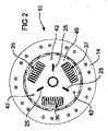
図を参照すると、クラッチプレート10が示されている。クラッチプレート10は、主プレート11と、主プレート11に固定される複数のフェイスセグメント13と、フェイスセグメント13の各側に固定される摩擦フェイス14および15とを有する。フェイスセグメント13を主プレート11に固定する技術はよく知られている。同様に、摩擦フェイス14および15をフェイスセグメント13に固定するための技術もよく知られている。
Referring to the figure, a
クラッチプレート10は、内側スプライン表面21を有するハブボス20をさらに有する。内側表面21は、車両変速機またはギアボックスに接続される相補的なスプラインシャフト(図示せず)を受け入れるようなサイズを有する。ハブボス20とシャフトとの間のスプライン接続により、ハブボス20に対してシャフトが相対的に軸方向に運動することが可能となるが、シャフトはハブボス20が回転するときにハブボス20と共に回転するように制約される。
The
段付肩部22がハブボス20の外側表面から側方に延在する。段付肩部22は図3に明瞭に示される。段付肩部22はクラッチプレート10の種々の取付部を受け入れることができるように複数の段を有し、上側環状リング23を形成する。リベット24がリング23に固定され、このリベット24は径方向の引張ばね25の一方の端部を受け入れる。
A stepped
ハブボス20はボス20の周りを延在する複数の歯30をさらに有し、これらの歯30は、ハブフランジ32内に形成される凹部31に噛合される。この構成は、クラッチプレート10の下面図である図4により良好に示される。各歯30が凹部31内で受けられ、また、この構成により、ハブボス20がハブフランジ32に対して、制限される角度変位で回転することができる。
The
径方向の引張ばね25が、ハブフランジ32に固定されるリベット33にその対向する端部が固定される。歯30および凹部31の構成により、ハブボス20さらにはそれによりハブボス20の環状リング23がハブフランジ32に対して回転することができることが認識されよう。したがって、それぞれのリベット24および33も互いに対して移動することができ、したがって、径方向の引張ばね25が弓形部分を介して伸長および収縮しながら振動することができる。さらに、このような相対運動が行われるときに、径方向の引張ばね25がリング23とハブフランジ32との間に付勢力を作用させ、相対運動が大きくなるにつれてこの付勢力が徐々に増大することが認識されよう。径方向の引張ばね25のこの付勢は、クラッチプレート10にねじり荷重がかかっていないときはハブ20およびハブフランジ32を元の位置に戻す傾向にある。
The opposite end of the
径方向の引張ばね25はクラッチプレート10の切欠部分内に示される。クラッチプレート10にはさらに2つの径方向の引張ばね25が設けられるが、これらは実質的に隠れている。それでもこれらの2つの径方向の引張ばね25も上で考察したばね25と同様の構造を有しかつそれと同様に動作する。これらの3つのばね25は互いに120°のところで等間隔に離間される。
A
クラッチプレート10は駆動ばね35、36および37をさらに有する。これらのばねは各々が外側ばね38および同軸の内側ばね39を備える。駆動ばね35から37は、ハブフランジ32と、副プレート40と、主プレート11との間で作用する。副プレート40は留めピン42により主プレート11に固定され、それにより、本明細書において上で定義したプレート組立体が形成される。したがって、副プレート40および主プレート11は相対的回転に逆らうように互いに固定される。
The
ハブフランジ32は、駆動ばね35から37によって制御される角度変位を通るようにプレート組立体11、40に対して回転することができる。最大角度変位は、ハブフランジ32の縁部内に形成される凹部43(図1で完全に見えるのは1つのみ)内に配置される留めピン42によって制御される。クラッチプレート10のこの態様は、従来技術のクラッチプレートで既に採用されている一構成である。
The
駆動モードにおけるクラッチプレート10の動作は以下の通りである。クラッチが係合されると、摩擦フェイス15が一方側において圧力プレートに摩擦係合されるように押圧され、さらにもう一方側において、内燃エンジンのクランクシャフトに接続されるフライホイールに摩擦係合されるように押圧される。このように摩擦係合されることにより、プレート組立体11、40が駆動されて回転される。この回転が駆動ばね35から37を介してハブフランジ32に伝達される。ハブフランジ32の回転が、径方向の引張ばね25を介しさらにその後ハブボス20の歯30を介して、ハブボス20に伝達される。上で説明したように、内燃エンジンにより発生する不規則な衝撃は、望ましくない駆動ラインノイズを発生させる可能性がある。このような駆動ラインノイズは、車両のギアがニュートラル状態にありかつクラッチが係合されているときに特に見られる。上で説明したように、これらの衝撃が、上で考察した構成を介して減衰され得る。
The operation of the
径方向の引張ばね25および駆動ばね35から37は、各々が、内燃エンジンからクラッチプレート10を介して伝達されるねじり振動を減衰する。径方向の引張ばね25は、それ以外の場合ではギアロールオーバーノイズを発生させるような振動を減衰し、そのようなノイズを減衰するためのこのばねの能力は、従来技術の円周方向のばねの場合と比較して径方向の向きのばねによって提供される変位の角度が広範囲であることにより、促進される。
The
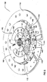
図5は本発明の代替の一形態を示すが、これは、図1から4までのクラッチプレート10に関連させて説明した種類の径方向の引張ばねを有する。図5では、図1の特徴の多くの部分が残っており、したがって、これらの特徴には同様の参照符号に100が足されている。
FIG. 5 shows an alternative form of the invention, which has a radial tension spring of the kind described in connection with the
したがって、クラッチプレート100は、本明細書において上で定義したプレート組立体を形成する主プレート111および副プレート140を有し、さらに、フェイスセグメント113ならびに摩擦フェイス114および115を有する。スプライン表面121を有するハブボス120が設けられる。一対の径方向の引張ばね125がハブボス120から延在するフランジまたはリング123の間を延在し、ハブフランジ132に固定されるリベット133に接続される。径方向の引張ばね125に関しては、クラッチ10内に設けられるばねが3つなのに対して、クラッチプレート100内に設けられるばねは2つのみである。
Thus, the
クラッチプレート100は、主プレート111と副プレート140を一体に堅固に接続させる複数の留めピン142と、ハブフランジ132内にある凹部143とをさらに有する。
The
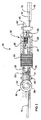
クラッチプレート100は、一対の湾曲する駆動ばね150、151をさらに有する。駆動ばね150、151は圧縮ばねであり、各々が実質的に一定の曲率半径を有し、また、これらは各々が実質的に径方向反対側の関係でハブボス120の周りに同心状に設置される。駆動ばね150および151はばね長およびばね定数が実質的に等しい。
The
駆動ばね150、151とクラッチプレート10の駆動ばね35、36および37とを視覚的に比較すると、クラッチプレート100の駆動ばねがクラッチプレート10の駆動ばねより有意に長いことが分かる。クラッチプレート10では、プレート組立体11、40とハブフランジ32との間で得られる角度変位を最大にするために、駆動プレート35、36および37がハブボス20の中心から最大距離のところに位置しなければならない。これにより駆動ばねの長さが最大となる。図1に見られるように、ハブフランジ32の直径が駆動ばねの最大長さを制限しており、したがって、より長い駆動ばねが必要となる場合、駆動ばねはハブボス20の方に向かって内側に移動されなければならない。しかし、ばねがハブボス20に接近するように移動される場合、ばねは、より外側に配置されるばねの場合と比較して、等しいトルクを伝達するためにはより高い強度を有することが必要となる。したがって、必要となる強度/トルクに適合させるためにばねのコイルの線径を増大させなければならないことから、広範囲の角度変位を得ることがより困難となる。
A visual comparison of the drive springs 150, 151 and the drive springs 35, 36 and 37 of the
再び図5のクラッチプレート100を参照すると、駆動ばね150、151が約60°に跨がって延在する。駆動ばね150および151の長さは、ばねの両端部を係合させることを目的としてプレート組立体111、140内およびハブフランジ132内で当接されることが必要であることから、それにより制限される。加えて、図5に示されるクラッチプレート100の形態では、駆動ばね150および151の長さは、駆動ばね150、151の両端部の間に径方向の引張ばね125を配置することが必要であることから、それによっても制限される。
Referring to the
駆動ばね150、151は適切なカーブを有するように製造され得るか、または、例えばクラッチプレート10の外側のばね38とある程度等しくなるように直線状の駆動ばねとして製造されてもよく、その場合、駆動ばねのカーブはクラッチプレート100の構造によって与えられる。例えば、図5では、駆動ばね150、151の各々がそれぞれのスロット152および153内に配置されていることが分かるが、図5で容易に確認することはできないが、これらのスロットは、駆動ばね150、151がスロット152、153の中に挿入されるときにばね150、151に必要となるカーブを与えるための湾曲する側方縁部を有する。
The drive springs 150, 151 can be manufactured to have an appropriate curve, or can be manufactured as a linear drive spring, for example, to be somewhat equal to the
さらに、主プレート111および副プレート140は、各々が、図5および6で確認することができる凹型の湾曲するばねガイド154、155を有する。図6は、図5のクラッチプレート100の下側から見た図を示す。ばねガイド154および155の各々がプレート111および140の中に形成されているのが分かるであろう。
Furthermore, the main plate 111 and the sub-plate 140 each have a concave
ばねガイド154および155は、駆動ばね150および151の湾曲形状を維持するのに貢献し得る。実際には、湾曲するばねガイド154および155は、駆動ばね150、151を湾曲する向きに維持する構造であってよい。このような構成では、中にばねが配置されているスロット152および153は、駆動ばね150、151を湾曲状に維持することに影響しなくてよい。
The spring guides 154 and 155 can contribute to maintaining the curved shape of the drive springs 150 and 151. In practice, the curved spring guides 154 and 155 may be structured to maintain the drive springs 150, 151 in a curved orientation. In such a configuration, the
別法として、スロット152、153および湾曲するばねガイド154、155の各々が、駆動ばね150、151を湾曲形状に維持することに貢献してもよい。
クラッチプレート100は一対の径方向の引張ばね125を有するように示されている。これらのばね125がクラッチプレート100の任意選択の付加部分として示されており、本発明によるクラッチプレートの特定の構成においては必要ではない可能性があることを認識されたい。しかし、クラッチプレート100は、駆動モードにおいて駆動ばね150、151を介してエンジンの衝撃を減衰することができ、さらに、クラッチが係合されるが変速機がニュートラル状態にあるアイドルモードにおいてはそれ以外ではギアロールオーバーノイズを発生させるようなエンジンの衝撃を減衰することができる。
Alternatively, each of the
The
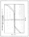
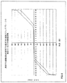
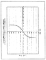
図7から10は、図1から6に示される本発明の形態の径方向の引張ばねを使用することにより得られる改善をグラフで示すものであり、ここでは、円周方向の圧縮ばねを採用する従来技術の構成と比較している。図7は直線状の径方向の引張ばねを有する一構成のグラフを示しており、図8は湾曲する径方向の引張ばねを有する一構成をグラフで示しており、これらは各々が本発明に従う。図9および10は従来技術の構成をグラフで示す。 FIGS. 7 to 10 graphically illustrate the improvements obtained by using the radial tension springs of the embodiment of the present invention shown in FIGS. 1 to 6, where a circumferential compression spring is employed. Compared with the configuration of the prior art. FIG. 7 shows a graph of one configuration with straight radial tension springs, and FIG. 8 shows a graph of one configuration with curved radial tension springs, each according to the present invention. . 9 and 10 graphically illustrate the prior art configuration.
図7および8のグラフから、図9および10に示されるグラフと比較して得られる角度変位が有意に増大していることが分かる。
本明細書で説明される本発明は、具体的に説明したもの以外の変更、修正および/または付加を受け入れることができ、また、本発明が、上記の説明の精神および範囲内にあるすべての変更、修正および/または付加を含むことを理解されたい。
From the graphs of FIGS. 7 and 8, it can be seen that the angular displacement obtained compared to the graphs shown in FIGS. 9 and 10 is significantly increased.
The invention described herein is susceptible to variations, modifications, and / or additions other than those specifically described, and is within the spirit and scope of the above description. It should be understood to include alterations, modifications and / or additions.
Claims (22)
出力シャフトに接続されるハブと、
前記プレート組立体によって回転するように駆動可能であるハブフランジと
を有し、
前記ハブが前記ハブフランジによって回転するように駆動可能であり、
前記ハブおよび前記ハブフランジが、角度方向において所定の範囲内で互いに対して変位可能であり、前記ハブの回転軸に対して径方向に延在しかつ前記ハブと前記ハブフランジとの間での相対的な角度変位に逆らうように付勢荷重を加える引張ばねによって、共に結合される、
クラッチプレート。 A plate assembly having an annular periphery, the assembly of friction material being attached to the annular periphery so as to face each other in opposite directions; and
A hub connected to the output shaft;
A hub flange that is drivable for rotation by the plate assembly;
The hub can be driven to rotate by the hub flange;
The hub and the hub flange are displaceable relative to each other within a predetermined range in an angular direction, extend radially with respect to the axis of rotation of the hub and between the hub and the hub flange Coupled together by a tension spring that applies a biasing load against the relative angular displacement,
Clutch plate.
出力シャフトに接続されるハブと、
前記プレート組立体によって回転するように駆動可能であるハブフランジと
を有し、
前記ハブが前記ハブフランジにより回転するように駆動可能であり、
前記プレート組立体および前記ハブフランジが、角度方向において所定の範囲内で互いに対して変位可能であり、前記ハブ周りに等間隔に配置される少なくとも2つの駆動ばねにより共に結合され、前記駆動ばねが圧縮ばねであり、湾曲しており、実質的に一定の曲率半径を有し、前記ハブの周りに同心状に設置され、前記駆動ばねが、前記プレート組立体と前記ハブフランジとの間での相対的な角度変位に逆らうように付勢荷重を加える、
クラッチプレート。 A plate assembly having an annular periphery, the assembly of friction material being attached to the annular periphery so as to face each other in opposite directions; and
A hub connected to the output shaft;
A hub flange that is drivable for rotation by the plate assembly;
The hub can be driven to rotate by the hub flange;
The plate assembly and the hub flange are displaceable relative to each other within a predetermined range in an angular direction, and are coupled together by at least two drive springs arranged at equal intervals around the hub, A compression spring that is curved, has a substantially constant radius of curvature, and is concentrically mounted about the hub, wherein the drive spring is disposed between the plate assembly and the hub flange; Apply a biasing load against the relative angular displacement,
Clutch plate.
Applications Claiming Priority (3)
| Application Number | Priority Date | Filing Date | Title |
|---|---|---|---|
| AU2011900820A AU2011900820A0 (en) | 2011-03-08 | Friction clutch assembly | |
| AU2011900820 | 2011-03-08 | ||
| PCT/AU2011/000807 WO2012119179A1 (en) | 2011-03-08 | 2011-06-29 | Friction clutch plate with damping springs |
Publications (2)
| Publication Number | Publication Date |
|---|---|
| JP2014511467A true JP2014511467A (en) | 2014-05-15 |
| JP2014511467A5 JP2014511467A5 (en) | 2015-04-30 |
Family
ID=46797314
Family Applications (1)
| Application Number | Title | Priority Date | Filing Date |
|---|---|---|---|
| JP2013556934A Pending JP2014511467A (en) | 2011-03-08 | 2011-06-29 | Friction clutch plate with damping spring |
Country Status (6)
| Country | Link |
|---|---|
| US (2) | US8978861B2 (en) |
| EP (1) | EP2683962A4 (en) |
| JP (1) | JP2014511467A (en) |
| KR (1) | KR20140035347A (en) |
| CN (1) | CN103502682B (en) |
| WO (1) | WO2012119179A1 (en) |
Families Citing this family (9)
| Publication number | Priority date | Publication date | Assignee | Title |
|---|---|---|---|---|
| US10024310B2 (en) * | 2011-04-28 | 2018-07-17 | Afglobal Corporation | Modular pump design |
| AU2012321075B2 (en) | 2012-05-14 | 2014-10-23 | Clutch Industries Pty Ltd | Friction clutch assembly |
| JP6559399B2 (en) * | 2014-02-27 | 2019-08-14 | 株式会社エクセディ | Damper device |
| FR3018878B1 (en) * | 2014-03-24 | 2017-12-22 | Valeo Embrayages | CLUTCH FRICTION DEVICE |
| FR3023599B1 (en) * | 2014-07-11 | 2016-07-01 | Valeo Embrayages | DAMPER FOR A MOTOR VEHICLE TORQUE TRANSMISSION DEVICE |
| US9739339B2 (en) * | 2015-01-07 | 2017-08-22 | GM Global Technology Operations LLC | Isolating torque coupler |
| US10468529B2 (en) * | 2017-07-11 | 2019-11-05 | Taiwan Semiconductor Manufacturing Co., Ltd. | Structure and formation method of semiconductor device structure with etch stop layer |
| DE102018120260A1 (en) * | 2018-08-21 | 2020-02-27 | Schaeffler Technologies AG & Co. KG | torsional vibration dampers |
| US11644787B2 (en) | 2019-12-06 | 2023-05-09 | Hewlett-Packard Development Company, L.P. | Clutch mechanism for a development system |
Citations (5)
| Publication number | Priority date | Publication date | Assignee | Title |
|---|---|---|---|---|
| JPS60142322U (en) * | 1984-03-01 | 1985-09-20 | アイシン精機株式会社 | clutch disc |
| JPS6213829A (en) * | 1985-07-11 | 1987-01-22 | ボルグ・ワ−ナ−・オ−トモ−テイブ・インコ−ポレ−テツド | Clutch driven plate assembly conducting damping having no backlash |
| EP0412559A1 (en) * | 1989-08-11 | 1991-02-13 | Fabryka Samochodow Osobowych Zaklad Sprzegiel | Clutch disc |
| JPH03272325A (en) * | 1990-03-22 | 1991-12-04 | Atsugi Unisia Corp | Clutch disc |
| JPH08121535A (en) * | 1994-10-24 | 1996-05-14 | Togo Seisakusho:Kk | Coil spring for damper |
Family Cites Families (28)
| Publication number | Priority date | Publication date | Assignee | Title |
|---|---|---|---|---|
| US3485063A (en) * | 1968-03-15 | 1969-12-23 | Deere & Co | Torsional isolator coupling |
| US4239097A (en) * | 1978-08-14 | 1980-12-16 | Borg-Warner Corporation | Multiple stage vibration damper assembly |
| FR2456264A1 (en) * | 1979-05-11 | 1980-12-05 | Ferodo Sa | TORSION DAMPING DEVICE, IN PARTICULAR A CLUTCH FRICTION, IN PARTICULAR FOR A MOTOR VEHICLE |
| US4499981A (en) * | 1982-09-27 | 1985-02-19 | Kabushiki Kaisha Daikin Seisakusho | Damper disc with concentric springs including hourglass-shaped springs to reduce the effect of centrifugal forces |
| JPS5972321U (en) * | 1982-11-08 | 1984-05-16 | トヨタ自動車株式会社 | clutch disc |
| JPS6043734U (en) * | 1983-09-02 | 1985-03-27 | 株式会社 大金製作所 | clutch disk |
| FR2602560B1 (en) * | 1986-08-06 | 1990-11-02 | Valeo | CLUTCH UNIT, AND APPLICATIONS IN PARTICULAR A CLUTCH FRICTION, A CLUTCH AND A HYDRAULIC COUPLING MEMBER COMPRISING SUCH A UNIT, PARTICULARLY FOR A MOTOR VEHICLE |
| JPS63110723U (en) * | 1987-01-09 | 1988-07-16 | ||
| DE3718848C2 (en) * | 1987-06-05 | 1995-11-23 | Fichtel & Sachs Ag | Clutch disc with idle damping device and frictional, centrifugal-dependent bypass |
| FR2624236B1 (en) * | 1987-12-08 | 1990-04-06 | Valeo | TORSION DAMPING DEVICE WITH LARGE ANGLE TRAVEL, ESPECIALLY CLUTCH FRICTION, ESPECIALLY FOR A MOTOR VEHICLE |
| FR2648883B1 (en) * | 1989-06-27 | 1993-01-22 | Valeo | TORSION DAMPING DEVICE, ESPECIALLY CLUTCH FRICTION FOR MOTOR VEHICLES |
| CA2083574C (en) * | 1991-12-27 | 2002-11-19 | Andrzej Szadkowski | Damped driven disc assembly |
| FR2725003B1 (en) * | 1994-09-28 | 1997-01-10 | Valeo | TORSION DAMPING DEVICE |
| FR2732426B1 (en) * | 1995-03-31 | 1997-05-16 | Valeo | TORSION DAMPING DEVICE WITH METAL SEATS FOR SPRINGS, PARTICULARLY FOR MOTOR VEHICLE |
| JP3640095B2 (en) * | 1995-06-30 | 2005-04-20 | アイシン精機株式会社 | Clutch disc |
| DE69634788T2 (en) * | 1995-07-24 | 2005-11-17 | Exedy Corp., Neyagawa | Damping disc unit with a friction mechanism with improved friction elements |
| JP3618158B2 (en) * | 1995-12-08 | 2005-02-09 | Nskワーナー株式会社 | Spring damper device for lockup clutch for torque converter |
| JP3363302B2 (en) * | 1996-02-16 | 2003-01-08 | 株式会社エクセディ | Plate member of damper disk assembly |
| JPH09242777A (en) * | 1996-03-08 | 1997-09-16 | Exedy Corp | Damper disk assembly |
| DE19654970C2 (en) * | 1996-08-05 | 2002-02-21 | Mannesmann Sachs Ag | torsional vibration damper |
| FR2754033B1 (en) * | 1996-09-30 | 2003-02-21 | Valeo | DOUBLE STEERING WHEEL WITH BALL BEARING, ESPECIALLY FOR A MOTOR VEHICLE |
| US6029793A (en) * | 1997-12-12 | 2000-02-29 | Exedy Corporation | Damper disk assembly |
| JPH11303890A (en) * | 1998-04-17 | 1999-11-02 | Exedy Corp | Plate and damper disc assembly |
| JP3732042B2 (en) * | 1999-06-14 | 2006-01-05 | 株式会社エクセディ | Damper mechanism and damper disk assembly |
| JP2002106639A (en) * | 2000-09-29 | 2002-04-10 | Exedy Corp | Damper mechanism |
| JP2002340095A (en) * | 2001-05-15 | 2002-11-27 | Exedy Corp | Damper mechanism |
| CN101061328B (en) * | 2004-11-20 | 2012-12-12 | 卢克摩擦片和离合器两合公司 | Torsional vibration damper |
| US7886887B2 (en) * | 2006-02-03 | 2011-02-15 | Eaton Corporation | Noise control using torsionally rigid damper stage |
-
2011
- 2011-06-29 EP EP11860120.2A patent/EP2683962A4/en not_active Withdrawn
- 2011-06-29 US US14/003,585 patent/US8978861B2/en not_active Expired - Fee Related
- 2011-06-29 CN CN201180070695.5A patent/CN103502682B/en not_active Expired - Fee Related
- 2011-06-29 WO PCT/AU2011/000807 patent/WO2012119179A1/en active Application Filing
- 2011-06-29 KR KR1020137025809A patent/KR20140035347A/en not_active Application Discontinuation
- 2011-06-29 JP JP2013556934A patent/JP2014511467A/en active Pending
-
2015
- 2015-02-26 US US14/632,627 patent/US20150198207A1/en not_active Abandoned
Patent Citations (5)
| Publication number | Priority date | Publication date | Assignee | Title |
|---|---|---|---|---|
| JPS60142322U (en) * | 1984-03-01 | 1985-09-20 | アイシン精機株式会社 | clutch disc |
| JPS6213829A (en) * | 1985-07-11 | 1987-01-22 | ボルグ・ワ−ナ−・オ−トモ−テイブ・インコ−ポレ−テツド | Clutch driven plate assembly conducting damping having no backlash |
| EP0412559A1 (en) * | 1989-08-11 | 1991-02-13 | Fabryka Samochodow Osobowych Zaklad Sprzegiel | Clutch disc |
| JPH03272325A (en) * | 1990-03-22 | 1991-12-04 | Atsugi Unisia Corp | Clutch disc |
| JPH08121535A (en) * | 1994-10-24 | 1996-05-14 | Togo Seisakusho:Kk | Coil spring for damper |
Also Published As
| Publication number | Publication date |
|---|---|
| CN103502682A (en) | 2014-01-08 |
| WO2012119179A1 (en) | 2012-09-13 |
| EP2683962A1 (en) | 2014-01-15 |
| KR20140035347A (en) | 2014-03-21 |
| EP2683962A4 (en) | 2016-08-10 |
| CN103502682B (en) | 2016-03-30 |
| US8978861B2 (en) | 2015-03-17 |
| US20150198207A1 (en) | 2015-07-16 |
| US20140027239A1 (en) | 2014-01-30 |
Similar Documents
| Publication | Publication Date | Title |
|---|---|---|
| JP2014511467A (en) | Friction clutch plate with damping spring | |
| JP6274796B2 (en) | Torque transmission device for automobile | |
| JP2015520342A (en) | Friction clutch assembly | |
| JP4738487B2 (en) | Vibration absorbing isolator | |
| JP6781791B2 (en) | Damper device | |
| WO2012063586A1 (en) | Lockup device for fluid coupling | |
| JP6656420B2 (en) | Isolating decoupler | |
| JP2017075694A (en) | Torque transmission device of automobile | |
| KR102356016B1 (en) | Spring assembly and lock-up device for torque converter including same | |
| JP5376061B2 (en) | Torque fluctuation absorber | |
| JP7351011B2 (en) | Vehicle vibration dampers and vehicles | |
| JP6338820B2 (en) | Flywheel damping device | |
| CN113124103A (en) | Torsional vibration damper for vehicle | |
| CN107636355B (en) | Belt pulley decoupler with slip guide shell | |
| CN113557370B (en) | Clutch driven disc and clutch | |
| KR101072610B1 (en) | Torsional vibration damper for hybrid vehicle | |
| JP6513512B2 (en) | Rotational fluctuation absorbing damper | |
| JP6512364B2 (en) | Damper device and starting device | |
| JP4956496B2 (en) | Torsional vibration reduction device | |
| KR101738065B1 (en) | Torque convertor for vehicle | |
| KR102340618B1 (en) | Dual mass flywheel | |
| CN112833111B (en) | Clutch driven disc and clutch | |
| CN111108304B (en) | Torque transmitting device, torsional damper and related assembly | |
| KR102025562B1 (en) | Torque convertor for vehicle | |
| JP6796583B2 (en) | Damper device |
Legal Events
| Date | Code | Title | Description |
|---|---|---|---|
| A521 | Request for written amendment filed |
Free format text: JAPANESE INTERMEDIATE CODE: A523 Effective date: 20140626 |
|
| A621 | Written request for application examination |
Free format text: JAPANESE INTERMEDIATE CODE: A621 Effective date: 20140626 |
|
| A521 | Request for written amendment filed |
Free format text: JAPANESE INTERMEDIATE CODE: A523 Effective date: 20150313 |
|
| A871 | Explanation of circumstances concerning accelerated examination |
Free format text: JAPANESE INTERMEDIATE CODE: A871 Effective date: 20150313 |
|
| A977 | Report on retrieval |
Free format text: JAPANESE INTERMEDIATE CODE: A971007 Effective date: 20150410 |
|
| A975 | Report on accelerated examination |
Free format text: JAPANESE INTERMEDIATE CODE: A971005 Effective date: 20150421 |
|
| A131 | Notification of reasons for refusal |
Free format text: JAPANESE INTERMEDIATE CODE: A131 Effective date: 20150423 |
|
| A601 | Written request for extension of time |
Free format text: JAPANESE INTERMEDIATE CODE: A601 Effective date: 20150717 |
|
| A02 | Decision of refusal |
Free format text: JAPANESE INTERMEDIATE CODE: A02 Effective date: 20160104 |