JP2014504792A - 改善されたダイナミクスを有する可動部位を含む開閉装置 - Google Patents
改善されたダイナミクスを有する可動部位を含む開閉装置 Download PDFInfo
- Publication number
- JP2014504792A JP2014504792A JP2013552202A JP2013552202A JP2014504792A JP 2014504792 A JP2014504792 A JP 2014504792A JP 2013552202 A JP2013552202 A JP 2013552202A JP 2013552202 A JP2013552202 A JP 2013552202A JP 2014504792 A JP2014504792 A JP 2014504792A
- Authority
- JP
- Japan
- Prior art keywords
- movable part
- elastic wire
- state
- switchgear according
- groove
- Prior art date
- Legal status (The legal status is an assumption and is not a legal conclusion. Google has not performed a legal analysis and makes no representation as to the accuracy of the status listed.)
- Granted
Links
Images

Classifications
-
- H—ELECTRICITY
- H01—ELECTRIC ELEMENTS
- H01H—ELECTRIC SWITCHES; RELAYS; SELECTORS; EMERGENCY PROTECTIVE DEVICES
- H01H1/00—Contacts
- H01H1/50—Means for increasing contact pressure, preventing vibration of contacts, holding contacts together after engagement, or biasing contacts to the open position
-
- H—ELECTRICITY
- H01—ELECTRIC ELEMENTS
- H01H—ELECTRIC SWITCHES; RELAYS; SELECTORS; EMERGENCY PROTECTIVE DEVICES
- H01H3/00—Mechanisms for operating contacts
- H01H3/32—Driving mechanisms, i.e. for transmitting driving force to the contacts
- H01H3/50—Driving mechanisms, i.e. for transmitting driving force to the contacts with indexing or locating means, e.g. indexing by ball and spring
-
- H—ELECTRICITY
- H01—ELECTRIC ELEMENTS
- H01H—ELECTRIC SWITCHES; RELAYS; SELECTORS; EMERGENCY PROTECTIVE DEVICES
- H01H3/00—Mechanisms for operating contacts
- H01H3/60—Mechanical arrangements for preventing or damping vibration or shock
-
- H—ELECTRICITY
- H01—ELECTRIC ELEMENTS
- H01H—ELECTRIC SWITCHES; RELAYS; SELECTORS; EMERGENCY PROTECTIVE DEVICES
- H01H33/00—High-tension or heavy-current switches with arc-extinguishing or arc-preventing means
- H01H33/60—Switches wherein the means for extinguishing or preventing the arc do not include separate means for obtaining or increasing flow of arc-extinguishing fluid
- H01H33/66—Vacuum switches
- H01H33/666—Operating arrangements
Landscapes
- High-Tension Arc-Extinguishing Switches Without Spraying Means (AREA)
- Driving Mechanisms And Operating Circuits Of Arc-Extinguishing High-Tension Switches (AREA)
- Springs (AREA)
Abstract
Description
Claims (15)
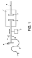
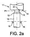
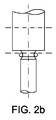
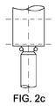
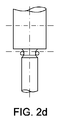
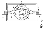
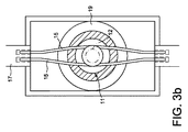
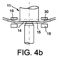
- それぞれ “開”状態及び “閉”状態と呼ばれる二つの主たる状態の間を移動可能な可動部位(11)を含む開閉装置であって、前記可動部位(11)が、円錐面(13、31)の領域により両端が規定される溝(12)を含む適切な形状によって特徴付けされ、前記円錐面の一方が、肩部(14)に取り付けられ、前記開閉装置は、前記可動部位が向かってスライドするロック部をさらに含み、このロック部は、前記溝が前記ロック部の前方にある場合に、前記溝に入るように、前記可動部位に向かって押され、続いて前記主たる状態の“開”状態に達し、前記ロック部が、前記可動部位の両側の二つの支持部(17)の間に延び、前記可動部位により撓められる、少なくとも一つの弾性ワイヤー(15)を含む。
- 前記可動部位(11)が、少なくとも一つの軸対称領域を有すること、
を特徴とする請求項1に記載の開閉装置。 - 前記弾性ワイヤーの端部が、前記支持部(17)に挿入され、前記支持部におけるその挿入量が変化すること、
を特徴とする請求項1に記載の開閉装置。 - 前記可動部位(11)に課される半径方向の力が、前記弾性ワイヤー(15)の直径、長さ、及び種類の選択によって、及び、前記可動部位(11)の外径及び前記支持部(17)における前記弾性ワイヤー(15)の位置の選択によって、決定されること、
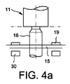
を特徴とする請求項1に記載の開閉装置。 - 前記可動部位(11)の移動方向に垂直な方向であり、“閉”状態に向かう前記可動部位の変位動作に対応する方向における、前記弾性ワイヤー(15)の変位を制限するための、ストッパー(19)を含むこと、
を特徴とする請求項1から4のいずれか1項に記載の開閉装置。 - 前記可動部位(11)の移動方向に垂直な方向であり、“開”状態に向かう方向における、前記弾性ワイヤーの変位を制限するための、ストッパー(30)を含むこと、
を特徴とする請求項1から5のいずれか1項に記載の開閉装置。 - 前記ストッパー(19)及び(30)が、前記可動部位(11)の変位方向に垂直であり、前記弾性ワイヤー(15)の直径よりも大きい距離を互いに隔てる、互いに平行な二つの面を規定し、前記距離が、前記可動部位(11)の移動方向における前記弾性ワイヤー(15)の変位を可能とするように選択され、前記変位の振幅が、前記弾性ワイヤー(15)がその弾性を有する範囲内に留まるように、制限されること、
を特徴とする請求項5または6に記載の開閉装置。 - 前記弾性ワイヤーに取り付けられるブレード(20)を含み、前記ブレードが、前記可動部位をスライドし、前記溝に侵入可能であること、
を特徴とする請求項1から7のいずれか1項に記載の開閉装置。 - 前記ブレードが取り付けられる、補強及び保持用の弾性ワイヤー(22)をさらに含むこと、
を特徴とする請求項8に記載の開閉装置。 - 前記ブレード(20)が、前記肩部(14)と前記円錐面(13)とにもたれて、前記溝(12)に侵入すること、
を特徴とする請求項8に記載の開閉装置。 - 前記可動部位の両側の二つの支持部の間に延び、前記可動部位により撓められる、第二の弾性ワイヤー(15)を含み、前記第二の弾性ワイヤーが、前記可動部位の両側で、基本的に同じであり、実質的に対称であること、
を特徴とする請求項1から10のいずれか1項に記載の開閉装置。 - 前記可動部位が、前記円錐面(13)の隣に、前記溝に向かって広がる円錐面(23)の領域を含み、前記可動部位(11)が“閉”位置に達した際に、前記弾性ワイヤー(15)が前記円錐面を押し付け、前記押し付けが、前記可動部位(11)を“閉”状態とする軸方向の力をもたらすように、前記円錐面(23)の領域の傾斜面が配向されていること、
を特徴とする請求項1から11のいずれか1項に記載の開閉装置。 - 前記弾性ワイヤー(15)が摺る可能性のある前記可動部位(11)の領域全体が、前記弾性ワイヤー(15)または前記可動部位(11)を損じる可能性のある、鋭利なエッジを有さないこと、
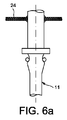
を特徴とする請求項1から12のいずれか1項に記載の開閉装置。 - 前記可動部位(11)には、固定された導体(5)への接続のための、導電性編組線(24)が取り付けられていること、
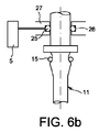
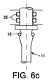
を特徴とする請求項1から13のいずれか1項に記載の開閉装置。 - 前記可動部位(11)には、前記可動部位を摺り、静止部品(9)における溝に収容され、固定された導体(5)との接続を保証する、少なくとも一つの導電性スプリング(25)が取り付けられていること、
を特徴とする請求項1から13のいずれか1項に記載の開閉装置。
Applications Claiming Priority (3)
| Application Number | Priority Date | Filing Date | Title |
|---|---|---|---|
| FR1150817A FR2971079B1 (fr) | 2011-02-02 | 2011-02-02 | Appareillage electrique comprenant une partie mobile a dynamique amelioree |
| FR1150817 | 2011-02-02 | ||
| PCT/EP2012/051752 WO2012104371A1 (fr) | 2011-02-02 | 2012-02-02 | Appareillage electrique comprenant une partie mobile a dynamique amelioree |
Publications (3)
| Publication Number | Publication Date |
|---|---|
| JP2014504792A true JP2014504792A (ja) | 2014-02-24 |
| JP2014504792A5 JP2014504792A5 (ja) | 2015-03-19 |
| JP5984221B2 JP5984221B2 (ja) | 2016-09-06 |
Family
ID=44544128
Family Applications (1)
| Application Number | Title | Priority Date | Filing Date |
|---|---|---|---|
| JP2013552202A Active JP5984221B2 (ja) | 2011-02-02 | 2012-02-02 | 改善されたダイナミクスを有する可動部位を含む開閉装置 |
Country Status (6)
| Country | Link |
|---|---|
| US (1) | US9202641B2 (ja) |
| EP (1) | EP2671239B1 (ja) |
| JP (1) | JP5984221B2 (ja) |
| CN (1) | CN103329231B (ja) |
| FR (1) | FR2971079B1 (ja) |
| WO (1) | WO2012104371A1 (ja) |
Families Citing this family (7)
| Publication number | Priority date | Publication date | Assignee | Title |
|---|---|---|---|---|
| EP2701254B1 (en) | 2012-08-23 | 2020-04-08 | General Electric Technology GmbH | Circuit interruption device |
| EP2701255B1 (en) | 2012-08-23 | 2016-05-04 | General Electric Technology GmbH | Circuit interruption device |
| EP2790285B1 (en) | 2013-04-12 | 2020-07-08 | General Electric Technology GmbH | Current limiter |
| CN108010758B (zh) * | 2017-12-25 | 2019-09-03 | 上海电气集团股份有限公司 | 一种带锁扣的斥力机构用绝缘拉杆装置 |
| CN115863103B (zh) * | 2022-12-16 | 2025-05-23 | 民众电气科技有限公司 | 一种带内置隔离开关的柱上断路器 |
| PL450373A1 (pl) * | 2024-11-27 | 2025-09-01 | Politechnika Warszawska | Rygiel mechaniczny |
| CN121394237B (zh) * | 2025-12-25 | 2026-04-07 | 广东电网有限责任公司 | 开关合闸保持装置和真空开关 |
Citations (4)
| Publication number | Priority date | Publication date | Assignee | Title |
|---|---|---|---|---|
| JPH11213826A (ja) * | 1998-01-27 | 1999-08-06 | Fuji Electric Co Ltd | 高速度遮断器 |
| JP2000251589A (ja) * | 1999-03-03 | 2000-09-14 | Mitsubishi Electric Corp | 開閉装置 |
| JP2005510669A (ja) * | 2001-11-21 | 2005-04-21 | バル・シール・エンジニアリング・カンパニー・インコーポレーテッド | ばねリングを備えたコネクタ |
| JP2009527877A (ja) * | 2006-02-23 | 2009-07-30 | シーメンス アクチエンゲゼルシヤフト | パワー半導体モジュールの短絡装置 |
Family Cites Families (8)
| Publication number | Priority date | Publication date | Assignee | Title |
|---|---|---|---|---|
| US2899837A (en) * | 1959-08-18 | skareen | ||
| AT258599B (de) * | 1965-07-19 | 1967-12-11 | Philips Nv | Schalteranordnung |
| US3908473A (en) * | 1974-01-09 | 1975-09-30 | Itt | Linear motion snap-action mechanism |
| DE2708082A1 (de) | 1977-02-25 | 1978-08-31 | Transformatoren Union Ag | Ueberspannungsableiter fuer mit schutzgas gefuellte, vollisolierte schaltanlagen |
| GB1585437A (en) | 1978-04-21 | 1981-03-04 | Lucas Industries Ltd | Index mechanism for rotary electric switch |
| FR2868198B1 (fr) * | 2004-03-29 | 2006-05-19 | Areva T & D Ag | Systeme de verrouillage pour une commande lineaire |
| TWI416568B (zh) | 2008-06-30 | 2013-11-21 | Hitachi Ltd | Vacuum switch and vacuum switch mechanism |
| FR2946455B1 (fr) | 2009-06-08 | 2011-07-01 | Areva T & D Sa | Commutateur de court-circuit a securite amelioree. |
-
2011
- 2011-02-02 FR FR1150817A patent/FR2971079B1/fr not_active Expired - Fee Related
-
2012
- 2012-02-02 WO PCT/EP2012/051752 patent/WO2012104371A1/fr not_active Ceased
- 2012-02-02 US US13/978,909 patent/US9202641B2/en active Active
- 2012-02-02 JP JP2013552202A patent/JP5984221B2/ja active Active
- 2012-02-02 CN CN201280006507.7A patent/CN103329231B/zh active Active
- 2012-02-02 EP EP12701759.8A patent/EP2671239B1/fr active Active
Patent Citations (4)
| Publication number | Priority date | Publication date | Assignee | Title |
|---|---|---|---|---|
| JPH11213826A (ja) * | 1998-01-27 | 1999-08-06 | Fuji Electric Co Ltd | 高速度遮断器 |
| JP2000251589A (ja) * | 1999-03-03 | 2000-09-14 | Mitsubishi Electric Corp | 開閉装置 |
| JP2005510669A (ja) * | 2001-11-21 | 2005-04-21 | バル・シール・エンジニアリング・カンパニー・インコーポレーテッド | ばねリングを備えたコネクタ |
| JP2009527877A (ja) * | 2006-02-23 | 2009-07-30 | シーメンス アクチエンゲゼルシヤフト | パワー半導体モジュールの短絡装置 |
Also Published As
| Publication number | Publication date |
|---|---|
| FR2971079A1 (fr) | 2012-08-03 |
| EP2671239A1 (fr) | 2013-12-11 |
| JP5984221B2 (ja) | 2016-09-06 |
| US20130299320A1 (en) | 2013-11-14 |
| WO2012104371A1 (fr) | 2012-08-09 |
| CN103329231B (zh) | 2016-01-20 |
| CN103329231A (zh) | 2013-09-25 |
| FR2971079B1 (fr) | 2013-03-01 |
| EP2671239B1 (fr) | 2014-11-12 |
| US9202641B2 (en) | 2015-12-01 |
Similar Documents
| Publication | Publication Date | Title |
|---|---|---|
| JP5984221B2 (ja) | 改善されたダイナミクスを有する可動部位を含む開閉装置 | |
| CN103370759B (zh) | 开关装置 | |
| US9748684B2 (en) | Plug connector and mating connector | |
| KR101247499B1 (ko) | 상하 접점 구조를 갖는 스프링 타입 프로브 핀 및 그 제조 방법 | |
| US7556542B2 (en) | Electrical connector in the form of a socket contact having a special lamellar construction | |
| CN111448635B (zh) | 真空开关管 | |
| JP2014110165A (ja) | 接点装置 | |
| CN103348432B (zh) | 一种包括锁定工具的真空断路器 | |
| EP3547455B1 (en) | Conductive terminal and connector | |
| JP2014504792A5 (ja) | ||
| CN108109871B (zh) | 限位开关 | |
| JP6495924B2 (ja) | 磁気形状記憶要素を備えるアクチュエータ装置 | |
| JP2018099769A (ja) | 微小機械部品および微小機械部品のための製造方法 | |
| JP6388737B1 (ja) | 開閉装置 | |
| EP2960918B1 (en) | Switch and button thereof | |
| KR101704989B1 (ko) | 회로차단기의 가동접촉자 | |
| JP2009199814A (ja) | 真空遮断器 | |
| JP6294544B1 (ja) | スイッチ構造 | |
| JP6364136B1 (ja) | スイッチ構造 | |
| KR100425189B1 (ko) | 개폐기 가동접점의 도전부 구조 | |
| JP2008058286A (ja) | 摺動型接触子 | |
| WO2016042737A1 (ja) | 接点装置、引き外し装置、および回路遮断器 | |
| JPH0972931A (ja) | 減速度検出装置 | |
| JP2004084775A (ja) | 緩衝器 |
Legal Events
| Date | Code | Title | Description |
|---|---|---|---|
| A521 | Request for written amendment filed |
Free format text: JAPANESE INTERMEDIATE CODE: A523 Effective date: 20150129 |
|
| A621 | Written request for application examination |
Free format text: JAPANESE INTERMEDIATE CODE: A621 Effective date: 20150129 |
|
| A977 | Report on retrieval |
Free format text: JAPANESE INTERMEDIATE CODE: A971007 Effective date: 20151028 |
|
| A131 | Notification of reasons for refusal |
Free format text: JAPANESE INTERMEDIATE CODE: A131 Effective date: 20151110 |
|
| A521 | Request for written amendment filed |
Free format text: JAPANESE INTERMEDIATE CODE: A523 Effective date: 20160209 |
|
| TRDD | Decision of grant or rejection written | ||
| A01 | Written decision to grant a patent or to grant a registration (utility model) |
Free format text: JAPANESE INTERMEDIATE CODE: A01 Effective date: 20160705 |
|
| A61 | First payment of annual fees (during grant procedure) |
Free format text: JAPANESE INTERMEDIATE CODE: A61 Effective date: 20160728 |
|
| R150 | Certificate of patent or registration of utility model |
Ref document number: 5984221 Country of ref document: JP Free format text: JAPANESE INTERMEDIATE CODE: R150 |
|
| R250 | Receipt of annual fees |
Free format text: JAPANESE INTERMEDIATE CODE: R250 |
|
| R250 | Receipt of annual fees |
Free format text: JAPANESE INTERMEDIATE CODE: R250 |
|
| R250 | Receipt of annual fees |
Free format text: JAPANESE INTERMEDIATE CODE: R250 |
|
| R250 | Receipt of annual fees |
Free format text: JAPANESE INTERMEDIATE CODE: R250 |
|
| R250 | Receipt of annual fees |
Free format text: JAPANESE INTERMEDIATE CODE: R250 |
|
| R250 | Receipt of annual fees |
Free format text: JAPANESE INTERMEDIATE CODE: R250 |
|
| R250 | Receipt of annual fees |
Free format text: JAPANESE INTERMEDIATE CODE: R250 |