JP2014214948A - Air conditioner - Google Patents
Air conditioner Download PDFInfo
- Publication number
- JP2014214948A JP2014214948A JP2013091831A JP2013091831A JP2014214948A JP 2014214948 A JP2014214948 A JP 2014214948A JP 2013091831 A JP2013091831 A JP 2013091831A JP 2013091831 A JP2013091831 A JP 2013091831A JP 2014214948 A JP2014214948 A JP 2014214948A
- Authority
- JP
- Japan
- Prior art keywords
- indoor
- air
- air conditioner
- indoor unit
- drain
- Prior art date
- Legal status (The legal status is an assumption and is not a legal conclusion. Google has not performed a legal analysis and makes no representation as to the accuracy of the status listed.)
- Granted
Links
- 238000007664 blowing Methods 0.000 claims description 2
- 239000003507 refrigerant Substances 0.000 abstract description 29
- 238000009434 installation Methods 0.000 abstract description 8
- XLYOFNOQVPJJNP-UHFFFAOYSA-N water Substances O XLYOFNOQVPJJNP-UHFFFAOYSA-N 0.000 description 43
- 238000001816 cooling Methods 0.000 description 15
- 238000004378 air conditioning Methods 0.000 description 12
- 230000004048 modification Effects 0.000 description 11
- 238000012986 modification Methods 0.000 description 11
- 238000010586 diagram Methods 0.000 description 9
- 238000005057 refrigeration Methods 0.000 description 9
- 239000007788 liquid Substances 0.000 description 8
- 238000009423 ventilation Methods 0.000 description 6
- 239000002184 metal Substances 0.000 description 5
- 238000004891 communication Methods 0.000 description 4
- 230000010365 information processing Effects 0.000 description 3
- 230000003068 static effect Effects 0.000 description 3
- 229910000831 Steel Inorganic materials 0.000 description 2
- 239000002826 coolant Substances 0.000 description 2
- 239000000498 cooling water Substances 0.000 description 2
- 239000000203 mixture Substances 0.000 description 2
- 238000005192 partition Methods 0.000 description 2
- 239000010959 steel Substances 0.000 description 2
- 230000007423 decrease Effects 0.000 description 1
- 230000001877 deodorizing effect Effects 0.000 description 1
- 230000014759 maintenance of location Effects 0.000 description 1
- 230000001681 protective effect Effects 0.000 description 1
- 230000003014 reinforcing effect Effects 0.000 description 1
- 238000000638 solvent extraction Methods 0.000 description 1
- 238000006467 substitution reaction Methods 0.000 description 1
- 239000013585 weight reducing agent Substances 0.000 description 1
Images


Classifications
-
- F—MECHANICAL ENGINEERING; LIGHTING; HEATING; WEAPONS; BLASTING
- F24—HEATING; RANGES; VENTILATING
- F24F—AIR-CONDITIONING; AIR-HUMIDIFICATION; VENTILATION; USE OF AIR CURRENTS FOR SCREENING
- F24F1/00—Room units for air-conditioning, e.g. separate or self-contained units or units receiving primary air from a central station
- F24F1/06—Separate outdoor units, e.g. outdoor unit to be linked to a separate room comprising a compressor and a heat exchanger
- F24F1/26—Refrigerant piping
- F24F1/32—Refrigerant piping for connecting the separate outdoor units to indoor units
-
- F—MECHANICAL ENGINEERING; LIGHTING; HEATING; WEAPONS; BLASTING
- F24—HEATING; RANGES; VENTILATING
- F24F—AIR-CONDITIONING; AIR-HUMIDIFICATION; VENTILATION; USE OF AIR CURRENTS FOR SCREENING
- F24F1/00—Room units for air-conditioning, e.g. separate or self-contained units or units receiving primary air from a central station
- F24F1/0003—Room units for air-conditioning, e.g. separate or self-contained units or units receiving primary air from a central station characterised by a split arrangement, wherein parts of the air-conditioning system, e.g. evaporator and condenser, are in separately located units
-
- G—PHYSICS
- G06—COMPUTING; CALCULATING OR COUNTING
- G06F—ELECTRIC DIGITAL DATA PROCESSING
- G06F1/00—Details not covered by groups G06F3/00 - G06F13/00 and G06F21/00
- G06F1/16—Constructional details or arrangements
- G06F1/20—Cooling means
Landscapes
- Engineering & Computer Science (AREA)
- General Engineering & Computer Science (AREA)
- Chemical & Material Sciences (AREA)
- Combustion & Propulsion (AREA)
- Mechanical Engineering (AREA)
- Theoretical Computer Science (AREA)
- Human Computer Interaction (AREA)
- Physics & Mathematics (AREA)
- General Physics & Mathematics (AREA)
- Devices For Blowing Cold Air, Devices For Blowing Warm Air, And Means For Preventing Water Condensation In Air Conditioning Units (AREA)
- Air Filters, Heat-Exchange Apparatuses, And Housings Of Air-Conditioning Units (AREA)
- Cooling Or The Like Of Electrical Apparatus (AREA)
Abstract
Description
本発明の実施形態は、空気調和機に関する。 Embodiments described herein relate generally to an air conditioner.
一般に、データセンターやサーバルームでは、種々の機能を有するサーバやネットワークを構築するための通信機器等の情報処理機器を収容している。 In general, a data center or a server room accommodates information processing devices such as a server having various functions and a communication device for constructing a network.
そして、これらデータセンターやサーバルームでは、これら情報処理機器を安定して動作させるために、常に機器動作に適した温度に維持するために、空調システムを具備している。 In these data centers and server rooms, in order to stably operate these information processing devices, an air conditioning system is provided in order to always maintain a temperature suitable for the device operation.
この種の従来の空調システムとしては、例えば特許文献1のようなものが知られている。
As this type of conventional air conditioning system, for example, the one disclosed in
上記特許文献1の空調システムは、室内ユニットである冷却ユニット10を、複数のドライコイルユニット12により構成している。各ドライコイルユニット12には熱交換器が設けられ、熱交換器13の冷媒供給口14および冷媒排出口15がドライコイルユニット12の側面から突出して設けられている。
In the air conditioning system of
このため、複数のドライコイルユニット12を並べて室内ユニットの冷却ユニットを構成する際に、熱源部分200からの冷媒配管と冷媒供給口14および冷媒排出口15とを接続するためのスペースが必要となるため、複数のドラルコイルユニット12同士を密接して配置することができず、室内ユニットの冷却ユニット10全体の設置スペースが大きくなっていた。
For this reason, when a plurality of
このような事情から、設置スペースの省スペース化を図った室内ユニットが求められている。 Under such circumstances, there is a demand for an indoor unit that saves installation space.
本発明が解決しようとする課題は、室内ユニットの設置スペースの省スペース化を図った空気調和機を提供することにある。 The problem to be solved by the present invention is to provide an air conditioner that saves space for installing an indoor unit.
実施形態の空気調和機は、機械室をそれぞれ有する複数台の室内ユニットと少なくとも1台の室外ユニットとを有する空気調和機において、複数台の室内ユニットを上下方向に重ねて複数段に形成している。 An air conditioner according to an embodiment is an air conditioner having a plurality of indoor units each having a machine room and at least one outdoor unit, and the plurality of indoor units are vertically stacked to form a plurality of stages. Yes.
また、これら室内ユニットの各機械室同士を上下方向に連通させ、室外ユニットの配管に接続される室内ユニットの配管接続端部を、最上段の室内ユニットの上部に設けた。 In addition, the machine rooms of these indoor units communicate with each other in the vertical direction, and the pipe connection end of the indoor unit connected to the pipe of the outdoor unit is provided in the upper part of the uppermost indoor unit.
以下、本発明の実施形態を図面を参照して説明する。なお、複数の図面中、同一または相当部分には同一符号を付している。 Hereinafter, embodiments of the present invention will be described with reference to the drawings. In addition, the same code | symbol is attached | subjected to the same or an equivalent part in several drawing.
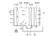
図1は実施形態に係る空気調和機の全体構成を示す模式図であり、フリークーリングシステム(FC)は図示省略している。この実施形態に係る空気調和機1は、R410A等の冷媒が循環する冷凍サイクルの冷媒熱交換器(室内熱交換器)と、フリークーリングシステム(FC)の水熱交換器を併設できるように構成されている。まず、図1に基づいて空気調和機の冷凍サイクルについて説明する。
すなわち、図1に示すように空気調和機1は、同形同大の複数台、例えば2台の室内ユニット2,3と、1台以上複数台、例えば2台の室外ユニット4,5とを具備している。ここで、各室内ユニット2,3の冷房定格(最大)能力はそれぞれ10馬力(28kW)であり、空気調和機1全体で20馬力(56kW)である。
That is, as shown in FIG. 1, the
これら2台の室内ユニット2,3は上下方向に複数段に積み重ねられて互いに固定され、1台の室内ユニット装置6に構成されている。
These two
上記各室内ユニット2,3は、後述するように立方体のフレーム構造(骨組み構造)の筺体7,8をそれぞれ有し、上段の室内ユニット2の筺体7の上端には、後述の天板39を設けている。また、これらの各筺体7,8内には、室内熱交換器9,10、室内ファン11,12等を収容する通風室2a,3aと、冷媒配管13等を収容する機械室2b,3bとを形成している。機械室2b,3bは上下一対の室内ユニット2,3を上下方向に連通可能に形成されている。冷媒配管13は、各室内熱交換器9,10に接続される液側冷媒配管13aと、ガス側冷媒配管13bとを具備している。
Each of the
すなわち、液側冷媒配管13aは、その先端部を2股に分岐する分岐管13a1,13a2を介して上下一対の室内熱交換器9,10の冷媒入口にそれぞれ接続されている。これら2股の各分岐管13a1,13a2は、その途中に、膨張弁15,16をそれぞれ介装している。この膨張弁15,16は、開度を調節可能な電子膨張弁である。
That is, the liquid-
ガス側冷媒配管13bも、その先端部を2股に分岐する分岐管13b1,13b2を介して上下一対の室内熱交換器9,10の各冷媒出口にそれぞれ接続されている。すなわち、上下2台の室内熱交換器9,10同士は並列に接続されている。
The gas-
そして、これら液側,ガス側冷媒配管13a,13bは、その図1中の上端部を、最上段の室内ユニット2の天板39の上端貫通孔14より上方外方へそれぞれ延出させ、その端部に液側,ガス側配管接続端部17,18をそれぞれ形成している。なお、液側,ガス側配管接続端部17,18は上段の室内ユニット2の上端部上に設けなくてもよく、配管接続作業を行う作業員の手が届く上端部近傍であれば上段の室内ユニット2の機械室2bの内部でもよい。
And these liquid side and gas side refrigerant |
この液側配管接続端部17には、少なくとも1台、例えば2台の冷媒室外ユニット4,5の各液側配管接続部にそれぞれ接続された液側冷媒接続配管19が接続される。
The liquid side pipe
また、室内ユニット2,3側のガス側配管接続端部18には、冷媒室外ユニット4,5の各ガス側配管接続部に接続されたガス側冷媒接続配管20が接続されている。すなわち、2台の冷媒室外ユニット4,5同士も並列に接続されている。
Further, gas side
各室外ユニット4,5は、その筺体内に、少なくとも図示省略の圧縮機、室外熱交換器、室外ファン等を配設しており、各室内ユニット2,3の室内熱交換器9,10とはマルチ接続されている。
Each
次に、上記室内ユニット装置6のより具体的な構成を説明する。
Next, a more specific configuration of the
本実施形態においては、フリークーリングシステム(FC)の水熱交換器を併設した場合について説明する。 In the present embodiment, a case where a water heat exchanger of a free cooling system (FC) is provided will be described.
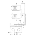
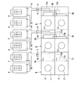
図2〜図9に示すように、室内ユニット装置6は、各室内ユニット2,3の筺体7,8を、例えばC形,L形等の形鋼により直方体のフレーム構造(骨組み構造)に構成しており、筺体7,8の背面(図3では上端)側に、空気の吸込口21を形成し、その正面(図3では下端)側に、空気の吹出口22を形成している。吸込口21は室内ユニット2,3の背面側をほぼ全面的に開口させて形成されており、水熱交換器26,27の背面のほぼ全面を露出させている。吹出口22は室内ユニット2,3の正面のほぼ全面を開口させて例えば正方形に形成されている。また、これら上下一対の筺体7,8同士の接合部の外周の各辺(四辺)には、金属製帯板状の補強板23をほぼ全周に亘って固定しており、この接合部の固定強度の向上が図られている。
As shown in FIG. 2 to FIG. 9, the
そして、図3に示すように、各筺体7,8は、その通風室2a,3aに、板金製等のほぼ角筒直胴状のインナーダクト(通風路)24,25を配設している。
As shown in FIG. 3, the
各インナーダクト24,25は、その吸込口21側に、室内熱交換器9,10をそれぞれ設け、その内部の吹出口22側に室内ファン11,12をそれぞれ設け、インナーダクト24,25を介して吸込口21と吹出口22とを対向させると共に連通させている。
Each of the
また、インナーダクト24,25は、室内熱交換器9,10と吸込口21側との間にて、フリークーリングシステムの水熱交換器26,27を追加して併設できるようにそれぞれ構成されている。
Further, the
フリークーリングシステムは、上下一対の水熱交換器26,27の図示省略の水入口同士と、各水出口同士を図示しない水配管の入側,出側水配管によりそれぞれ連結して上下一対の水熱交換器26,27同士を並列に接続している。そして、これら入側,出側水配管は機械室2bの上方へ延出し、図5、図7に示すように冷媒配管の液側,ガス側配管接続端部17,18と同様に入側,出側配管接続端部50,51を形成している。これら水配管の入側,出側配管接続端部50,51は図示省略の接続水配管を介してクーリングタワー等の水冷却器に接続される。クーリングタワーも少なくとも1台でよいが、複数台、例えば2台の場合には、室外ユニット4,5と同様に図示省略の連結用水配管により並列に接続される。水熱交換器26,27内を通水する冷却水流量は水配管途中に介装された電動二方弁の開度と水循環ポンプ(いずれも図示しない)の回転数により制御される。なお、フリークーリングシステムは、空気調和機1の冷凍サイクルによる冷房定格(最大)能力と同等の能力を出力できるように水熱交換器26,27の容量が設定されている。
In the free cooling system, a pair of upper and lower
インナーダクト24,25は、ほぼ角筒直胴状のダクトよりなり、水熱交換器26,27、室内熱交換器9,10と、室内ファン11,12とを結ぶ空気流路を、これら熱交換器9,10、水熱交換器26,27の横幅とほぼ同じ断面の空気流路(通風路)に形成している。
The
室内ファン11,12は、例えばプロペラファンやターボファン等のファンに、DC直流ファンモータ等のモータを一体に設けることにより構成されている。図2〜図5に示すように本実施形態では、ファンにターボファンを採用している。室内ファン11,12はファン外面を覆う図示省略のファンガードを備えており、このファンガードの中央部外面には、ファンモータの外面を被覆して保護する保護カバーを設けている。
The
室内ファン11,12は、インナーダクト24,25に設けられた取付板24a,25bに取り付けられている。この取付板24a,25bによって、インナーダクト24,25は室内ファン11,12の一次側(室内熱交換器側)と二次側(吹出口22側)とに仕切られている。図2に示すように、インナーダクト24,25の二次側は、その流路断面が略正方形に形成されている。インナーダクト24,25の一次側と二次側の横幅寸法は同一である。インナーダクト24,25の縦方向寸法は、一次側の下面に後述する傾斜板34(図8)を設ける分、二次側に比べて一次側の方が小さくなる。そして、インナーダクト24,25の二次側流路断面(吹出口22)の縦方向寸法Lh、幅方向寸法Lwをそれぞれ1000mmとしている。そして、室内ファン11,12のターボファンの直径D1を500mmとしている。二次側流路形状を正方形とし、ターボファンの直径D1を流路断面寸法(Lh,Lw)の略1/2とすることが送風効率の面で最も好ましい。
The
図11に室内ファン11,12のファンにプロペラファンを採用した室内ユニット装置6を示す。インナーダクト24,25の2次側流路断面寸法Lh,Lwは1000mmで同じであるが、プロペラファンの直径D2を630mmとしている。このようにプロペラファンを用いる場合には、プロペラファンの直径D2を流路断面寸法(Lh,Lw)の略3/5とすることが送風効率の面で最も好ましい。
FIG. 11 shows an
図3等に示すように、インナーダクト24,25の一側面と、室内ユニット2,3の外側面(図3では右側面)との間には、上記機械室2b,3bが形成されている。この機械室2b,3bは図1,図6に示すように、上下一対の室内ユニット2,3の上下方向に連通するように形成され、上記冷媒配管13や水配管、図5で示す主制御基板28、副制御基板29、冷媒配管13に介装された膨張弁15,16等が収容される。
As shown in FIG. 3 and the like, the
図7に示すように膨張弁15,16は室内ユニット2,3の背面側または、その近傍に配設され、背面側から容易にアクセスし、メンテナンスできるようになっている。
As shown in FIG. 7, the
また、図5で示す主制御基板28は、2台の室内ユニット2,3の運転を統合制御する制御装置であり、例えば上段の室内ユニット2の機械室2b内に配設される。副制御基板29は室内ユニット2,3の各々の機械室2b,3b内に配設され、室外ユニットの制御装置からの指令により、各膨張弁15,16の開度等を制御する制御装置である。
Further, the
下段の室内ユニット3の筐体8には、その底部左右端部の外面に、所定高さ(厚さ)の左右一対の角柱状の基台30a,30bを配設し、これら基台30a,30bを介して室内ユニット装置6を所要の設置面に設置固定し、この設置面と下段の室内ユニット3の外底面との間に所要の間隙を形成している。
The
そして、図8,図9に示すように各室内ユニット2,3は、各室内熱交換器9,10と各水熱交換器26,27の下部かつインナーダクト24,25の下部であって、室内熱交換器9,10の空気流下流側(二次側)に、これら室内,水熱交換器9,10,26,27で発生したドレンを受ける第1のドレンパン31を設けている。第1のドレンパン31は、その図8中上面に、室内熱交換器9,10よりも空気流下流側で連通する受水口32を設ける一方、第1のドレンパン31の下部に排水口33を設けている。この排水口33は図8では短管状に図示しているが、単なる排水口でもよい。この第1のドレンパン31は、その受水口32を有する図8中の上面と、排水口33の高さを、室内ファン11,12の一次側(室内熱交換器9,10の二次側)の静圧と室内静圧との最大差圧よりも十分に余裕のある高さに設定している。
As shown in FIGS. 8 and 9, the
これにより、室内ファン11,12による静圧低下によりインナーダクト24,25内にドレンが滞留することを未然に防止できる。
Thereby, it is possible to prevent the drain from staying in the
また、インナーダクト24,25の底面には、室内熱交換器9,10の空気流下流側にて、傾斜板34を設けている。傾斜板34は室内ファン11,12側から室内熱交換器9,10に向けて漸次低くなる所要の傾斜角により形成されており、室内熱交換器9,10からのドレンの飛沫を受けて、第1のドレンパン31の受水口32へ案内し排水するようになっている。
Further, inclined
そして、図9にも示すように、第1のドレンパン31の下方には、このドレンパン31の排水口33から排水されるドレンと、室内熱交換器9,10と水熱交換器26,27からのドレンを受ける第2のドレンパン35をそれぞれ設けている。第2のドレンパン35は、そのドレン受水側開口を第1のドレンパン31よりも大きく形成し、その一端部(図9では左端部)を機械室2b,3b側まで若干延在させている。
As shown in FIG. 9, below the
また、下段の室内ユニット3の機械室2bの下部には、機械室2b,3bの冷媒配管13等から滴下するドレンを受けて第2のドレンパン35内へ案内する第3のドレンパン36を設けている。
Further, a
さらに、図7に示すように各室内ユニット2,3の機械室2b,3bの背面側底部外面には、短管状の外部ドレン排水口部37と短管状の予備ドレン管38を並設している。
Further, as shown in FIG. 7, a short tubular
外部ドレン排水口部37は、その内側開口端を各第2のドレンパン35の内部に連通させ、第2のドレンパン35内のドレンを外部ドレン排水口部37から外部へ排水する。この外部ドレン排水口部37には、例えば防臭用のトラップを有する図示省略の外部ドレン排水管が接続される。
The external drain
予備ドレン管38は、外部ドレン排水口37より上部に配置され、通常は排水されないが、万一、外部ドレン排水口37が詰まった場合にも、第2のドレンパン35内のドレンを排水するので、空調運転の継続が可能である。予備ドレン管38に接続される図示省略の接続管に水を検知するセンサを設けることにより、外部ドレン排水口37の詰まりを検出できる。
The
そして、上述したように図5や図7等で示す上段の室内ユニット2の上端に、天板39を設けている。天板39の図中上面には、その正面から見て左右端部に、図示省略の運搬用ロープを掛止させる左右一対のロープガイド40a,40bが設けられている。これらロープガイド40a,40bは、例えばコ字形の形鋼よりなり、そのコ字形開口を図中上方へ向けて天板39の正面側一端から背面側他端までほぼ全長に亘って取付けられている。
As described above, the
したがって、大重量の室内ユニット装置6を運搬する場合に、これら左右一対のロープガイド40a,40bに運搬用ロープを掛け、運搬中のロープの外れを未然に防止できる。
Therefore, when the heavy
また、ロープガイド40a,40bは室内ユニット装置6の筐体の強度を補強できるので、室内ユニット装置6の運搬時の室内ユニット装置6の変形や歪みの発生の防止または低減を図ることができる。
Moreover, since the rope guides 40a and 40b can reinforce the strength of the housing of the
さらに、図5,図7に示すように室内ユニット装置6は、その上下一対の各室内ユニット2,3の背面側の吸込口21,21を含む開口を所要の間隔を置いてほぼ全面的にそれぞれ閉塞する、例えば板金製の背面パネル41a,41bを取付可能に構成されている。
Further, as shown in FIGS. 5 and 7, the
これら背面パネル41a,41bは、例えば空調負荷が小さいために、室内ユニット2,3の一方の運転を停止させる場合や故障で運転停止させる場合に、その一方の運転を停止させる室内ユニット2,3の背面に取り付けて吸込口21を閉塞することにより、吹出口22から吹き出された調温吹出風が吸込口21,21に吸い込まれるショートサーキットの防止または低減を図ることができる。
These
また、各室内ユニット2,3は、その左右側面に、その左右側面開口を閉塞する左右一対の板金製の側面パネル42a,42bを取付可能に構成されている。これら側面パネル42a,42bは取り付けない場合でも、インナーダクト24,25により通風路が確保され、空調運転可能であるので、取り付けなくてもよく、その場合はコスト低減と軽量化を図ることができる。側面パネル42a,42bを取り付ける場合には外観の向上を図ることができる。
Each of the
さらにまた、各室内ユニット2,3は、その機械室2b,3bの正面側に、その正面開口を閉塞する上下一対の板金製の上下一対の正面パネル43a,43bを取付可能に構成されている。上部の正面パネル43aの外面には、空調運転を操作するための操作部44を設けている。
Furthermore, each
このように構成された空気調和機1では、空調負荷とFC(フリークーリング)の冷却水温度とに基づいて、次の4つの運転モードにより運転制御される。
(1)外気温が低く、空調負荷が小さいときは、FCのみを運転し、冷凍サイクルは運転を停止する。FCは省電力であるので、FCを最大限利用する。
(2)上記(1)よりも空調負荷が所定値大きい場合は、冷凍サイクルの圧縮機を最小能力に固定して運転し、FCの能力を可変に制御する。FCの能力は図示省略の二方弁の開度制御と、水循環ポンプの回転数制御等により行われる。
(3)さらに、上記(2)よりも空調負荷が所定値大きい場合は、FCの能力を最大に固定(例えば二方弁の開度を全開(100%)に固定)し、冷凍サイクルの圧縮機の能力を可変に制御する。
(4)盛夏期等外気温が高く、FCの温水が高温である場合、FCを運転すると、冷房ではなく、むしろ暖房してしまうような状態ではFCの運転を停止し、冷凍サイクルのみを運転する。
In the
(1) When the outside air temperature is low and the air conditioning load is small, only the FC is operated, and the refrigeration cycle is stopped. Since FC saves power, it uses FC as much as possible.
(2) When the air conditioning load is larger than the above (1) by a predetermined value, the compressor of the refrigeration cycle is operated with the minimum capacity, and the FC capacity is controlled variably. The FC capacity is controlled by controlling the opening of a two-way valve (not shown) and controlling the rotational speed of a water circulation pump.
(3) Furthermore, when the air conditioning load is larger than the above (2), the FC capacity is fixed to the maximum (for example, the opening of the two-way valve is fully opened (100%)) and the refrigeration cycle is compressed. Variable control of the machine's ability.
(4) When the outside air temperature is high, such as in midsummer, and the hot water of the FC is hot, when the FC is operated, it is not cooled but rather it is heated, and the FC is stopped and only the refrigeration cycle is operated. To do.
このように空気調和機1によれば、冷凍サイクルとFCの連携制御が可能であり、また、空調負荷に応じて、これら両系の運転を統合的に制御できるので、省電力を図ることができる。
Thus, according to the
そして、この空気調和機1によれば、2台の室内ユニット2,3を上下方向に積み重ねて複数段に形成しているので、これら室内ユニット2,3を横並びで設置する場合よりも、設置スペースの節約を図ることができる。
And according to this
さらに、冷凍サイクルの液側,ガス側配管接続端部17,18とFC系の入側,出側配管接続端部(図示省略)を上段の室内ユニット2の上端面上に設けたので、サーバルーム等室内の天井スペースを利用して冷媒系とFC系の配管を設けることにより、これら配管接続端部17,18との配管接続スペースの節約を図ることができる。これにより、図14に示すように複数の室内ユニット装置6を横並びで設置する場合、室内ユニット装置6を互いに密接して設置することが可能になり、設置スペースの節約を図ることができる上に、室内ユニット装置6の増設時や交換時において、配管類が邪魔になることがないので、室内ユニット装置6を追加、撤去作業が容易となる。
Further, since the liquid side and gas side pipe connection ends 17 and 18 of the refrigeration cycle and the inlet side and outlet side pipe connection ends (not shown) of the FC system are provided on the upper end surface of the upper
また、この空気調和機1によれば、複数台の室内ユニット2,3を、室外ユニット4,5に対し並列に接続して、いわゆるマルチ接続しているので、これら室内ユニット2,3の一方が故障等により万一運転停止した場合でも、その他方により運転を継続できる。このために、高価なサーバや通信機器等、情報処理機器等が温度上昇によりダウンすることを防止または低減できる。
Further, according to the
さらに、インナーダクト24,25は、室内熱交換器9,10や水熱交換器26,27の横幅とほぼ同一の流路の断面を有する空気流路を形成するので、圧損を低減できる。すなわち、吸込口21から室内ユニット2,3内に吸い込まれた空気が水熱交換器26,27、室内熱交換器9,10を経て室内ファン11,12に至るまでの空気流路に、拡幅や縮小が発生すると圧損が発生するが、インナーダクト24,25はこの空気流路の断面の横幅を、室内,水熱交換器9,10,26,27の横幅とほぼ同一に維持するので、圧損を低減できる。このために、室内ファン11,12の消費電力の節電を図ることができる。
Furthermore, since the
また、室内熱交換器9,10で発生したドレンを受ける第1のドレンパン31の受水口32を室内熱交換器9,10の下流側にて、インナーダクト24,25の下部に設け、この受水口32を有する第1のドレンパン31の図中上面と排水口33との高さを、室内ファン11,12の一次側の最大負圧よりも十分に低い負圧になるように形成している。
Further, a
このために、負圧差により、第1のドレンパン31内のドレンを排水口33から第2のドレンパン35内へ強制的に排水できる。これにより、インナーダクト24,25の内底面にドレンが滞留することを低減できる。また、第2のドレンパン35のドレンは外部ドレン排水口部37から外部へ排水できる。さらに、万一、この外部ドレン排水口部37に詰まりが発生した場合でも予備ドレン管38により外部へ排水できる。
For this reason, the drain in the
さらにまた、室内熱交換器9,10の空気流下流側にて、インナーダクト24,25の底面に、傾斜板34を設けたので、室内,水熱交換器9,10,26,27から空気流に乗って飛散する飛沫状のドレンを傾斜板34により受けて、その下り傾斜面により第1のドレンパン31に案内し排水できる。これによっても、インナーダクト24,25の内底面に滞留するドレンの低減を図ることができる。
Furthermore, since the
そして、適宜フリークーリング(FC)の水熱交換器26,27を追加し、併設できるので、冷凍サイクルを用いた空気調和機とFCによる水熱交換器とを別々に設置する場合に比して設置スペースの節約とコスト低減を図ることができる。
And, since free cooling (FC)
図10は上記室内ユニット2,3の変形例を示す平断面図である。この変形例は上記図3で示すインナーダクト24,25の室内ファン11,12側端部に、所要の直径に縮径する縮径部45を形成したものであり、これ以外の構成は上記図3で示すインナーダクト24,25と同様の構成である。
FIG. 10 is a plan sectional view showing a modification of the
この図10で示すインナーダクト24,25によれば、室内ファン11,12をインナーダクト24,25に取り付ける平板状の取付板24a,25aと、この取付板24a,25a側のインナーダクト24,25の一端とにより形成される角部に流入する空気流を縮径部45により室内ファン11,12へスムースに案内することができるので、流路抵抗を低減できる。このために、室内ファン11,12の消費電力の節約を図ることができる。
According to the
図12は上記空気調和機1の変形例の全体構成を示す模式図である。この変形例は上記図1で示す室内ユニット2と室内ユニット3が並列に接続されたマルチ接続ではなく、室内ユニット2と室内ユニット3が独立して室外ユニット4,5にそれぞれ接続された1対1接続としたものである。この場合、室内ユニット2,3が並列に接続されていないため、分岐管は不要となる。また、室外ユニット4,5もマルチ接続に対応した室外ユニットではなく、より安価な1対1接続用の室外ユニットを用いることができる。
FIG. 12 is a schematic diagram showing an overall configuration of a modification of the
この図12に示す空気調和機1によれば、さらにコスト低減を図ることができる。
According to the
なお、上記機械室2b,3bでは、室内ユニット2,3の上下方向に単に連通する連通空間に形成する場合について述べたが、本発明はこれに限定されるものではなく、例えば機械室2b,3b内を室内ユニット2,3に対応して上下方向に仕切る仕切り板を設け、この仕切り板に、冷媒配管13や水配管等を貫通させる貫通孔を設けることにより、上下の機械室2b,3bを連通させてもよい。また、これら連通孔の所要数をノックアウト孔により形成してもよい。
In the
図13は上記空気調和機1の他の変形例の全体構成を示す模式図である。この変形例は上記図1で示す液側,ガス側配管接続部17,18を最下段の室内ユニット3の下面に設けたものであり、これ以外の構成は上記図1で示す室内ユニット装置6と同様の構成である。この図13に示す空気調和機1においても設置スペースの節約によれば、さらにコスト低減を図ることができる。
FIG. 13 is a schematic diagram showing an overall configuration of another modification of the
以上、本発明の幾つかの実施形態を説明したが、これらの実施形態は、例として提示したものであり、本発明の範囲を限定することは意図していない。これら新規な実施形態は、その他の様々な形態で実施されることが可能であり、本発明の要旨を逸脱しない範囲で、種々の省略、置換え、変更を行なうことができる。これら実施形態やその変形は、本発明の範囲や要旨に含まれるとともに、特許請求の範囲に記載された発明とその均等の範囲に含まれる。 As mentioned above, although several embodiment of this invention was described, these embodiment is shown as an example and is not intending limiting the range of this invention. These novel embodiments can be implemented in various other forms, and various omissions, substitutions, and changes can be made without departing from the scope of the present invention. These embodiments and modifications thereof are included in the scope and gist of the present invention, and are included in the invention described in the claims and the equivalents thereof.
1…空気調和機、2,3…室内ユニット、2b,3b…機械室、4,5…室外ユニット、9,10…室内熱交換器、11,12…室内ファン、13…冷媒配管、17…液側配管接続端部、18…ガス側配管接続端部、24,25…インナーダクト(通風路)、26,27…水熱交換器、31…第1のドレンパン、32…受水口、33…排水口、34…傾斜板、35…第2のドレンパン、36…第3のドレンパン、37…外部ドレン排水口部、39…天板、40a,40b…ロープガイド。
DESCRIPTION OF
Claims (6)
前記複数台の室内ユニットを上下方向に重ねて複数段に形成し、これら室内ユニットの各機械室同士を上下方向に連通させ、前記室外ユニットの配管に接続される前記室内ユニットの配管接続端部を、前記最上段の室内ユニットの上部に設けたことを特徴とする空気調和機。 In an air conditioner having a plurality of indoor units each having a machine room and at least one outdoor unit,
The plurality of indoor units are vertically stacked to form a plurality of stages, the machine rooms of these indoor units communicate with each other in the vertical direction, and the pipe connection end of the indoor unit connected to the pipe of the outdoor unit Is provided above the uppermost indoor unit.
Priority Applications (3)
| Application Number | Priority Date | Filing Date | Title |
|---|---|---|---|
| JP2013091831A JP6126447B2 (en) | 2013-04-24 | 2013-04-24 | Air conditioner |
| PCT/JP2014/060664 WO2014175109A1 (en) | 2013-04-24 | 2014-04-15 | Air conditioner |
| TW103114393A TW201512605A (en) | 2013-04-24 | 2014-04-21 | Air conditioner |
Applications Claiming Priority (1)
| Application Number | Priority Date | Filing Date | Title |
|---|---|---|---|
| JP2013091831A JP6126447B2 (en) | 2013-04-24 | 2013-04-24 | Air conditioner |
Publications (2)
| Publication Number | Publication Date |
|---|---|
| JP2014214948A true JP2014214948A (en) | 2014-11-17 |
| JP6126447B2 JP6126447B2 (en) | 2017-05-10 |
Family
ID=51791688
Family Applications (1)
| Application Number | Title | Priority Date | Filing Date |
|---|---|---|---|
| JP2013091831A Active JP6126447B2 (en) | 2013-04-24 | 2013-04-24 | Air conditioner |
Country Status (3)
| Country | Link |
|---|---|
| JP (1) | JP6126447B2 (en) |
| TW (1) | TW201512605A (en) |
| WO (1) | WO2014175109A1 (en) |
Cited By (3)
| Publication number | Priority date | Publication date | Assignee | Title |
|---|---|---|---|---|
| JP2017146026A (en) * | 2016-02-17 | 2017-08-24 | 東芝キヤリア株式会社 | Air conditioner |
| JP2018205426A (en) * | 2017-05-31 | 2018-12-27 | 株式会社荏原製作所 | Silencing unit and silencing structure using the same |
| JP2020085412A (en) * | 2018-11-30 | 2020-06-04 | 国立研究開発法人農業・食品産業技術総合研究機構 | Heat exchange device |
Families Citing this family (1)
| Publication number | Priority date | Publication date | Assignee | Title |
|---|---|---|---|---|
| JP6972358B2 (en) * | 2018-08-17 | 2021-11-24 | 三菱電機株式会社 | Free cooling system |
Citations (10)
| Publication number | Priority date | Publication date | Assignee | Title |
|---|---|---|---|---|
| JP2000283548A (en) * | 1999-03-29 | 2000-10-13 | Sanyo Electric Co Ltd | Built-in air conditioner |
| US20090188264A1 (en) * | 2008-01-25 | 2009-07-30 | Philip Chappelle Fair | Modular in-frame pumped refrigerant distribution and heat removal system |
| US20090241578A1 (en) * | 2008-03-31 | 2009-10-01 | Exaflop Llc | Warm Floor Data Center |
| JP2010243081A (en) * | 2009-04-07 | 2010-10-28 | Hitachi Appliances Inc | Indoor unit of air conditioner |
| US20110056651A1 (en) * | 2008-05-05 | 2011-03-10 | Carrier Corporation | Integrated computer equipment container and cooling unit |
| JP2011220665A (en) * | 2010-03-23 | 2011-11-04 | Kanden Energy Solution Co Inc | Air conditioning system |
| US20120138285A1 (en) * | 2010-12-01 | 2012-06-07 | Hitachi, Ltd. | Electronic apparatus rack and data center |
| US20120302150A1 (en) * | 2008-10-31 | 2012-11-29 | Ty Schmitt | System And Method For Vertically Stacked Information Handling System And Infrastructure Enclosures |
| US20130010423A1 (en) * | 2010-04-16 | 2013-01-10 | Exaflop LLC, a Delaware corporation | Evaporative Induction Cooling |
| US20130019627A1 (en) * | 2010-03-30 | 2013-01-24 | Nec Corporation | Cooling apparatus and cooling system for electronic-device exhaustion |
-
2013
- 2013-04-24 JP JP2013091831A patent/JP6126447B2/en active Active
-
2014
- 2014-04-15 WO PCT/JP2014/060664 patent/WO2014175109A1/en active Application Filing
- 2014-04-21 TW TW103114393A patent/TW201512605A/en unknown
Patent Citations (10)
| Publication number | Priority date | Publication date | Assignee | Title |
|---|---|---|---|---|
| JP2000283548A (en) * | 1999-03-29 | 2000-10-13 | Sanyo Electric Co Ltd | Built-in air conditioner |
| US20090188264A1 (en) * | 2008-01-25 | 2009-07-30 | Philip Chappelle Fair | Modular in-frame pumped refrigerant distribution and heat removal system |
| US20090241578A1 (en) * | 2008-03-31 | 2009-10-01 | Exaflop Llc | Warm Floor Data Center |
| US20110056651A1 (en) * | 2008-05-05 | 2011-03-10 | Carrier Corporation | Integrated computer equipment container and cooling unit |
| US20120302150A1 (en) * | 2008-10-31 | 2012-11-29 | Ty Schmitt | System And Method For Vertically Stacked Information Handling System And Infrastructure Enclosures |
| JP2010243081A (en) * | 2009-04-07 | 2010-10-28 | Hitachi Appliances Inc | Indoor unit of air conditioner |
| JP2011220665A (en) * | 2010-03-23 | 2011-11-04 | Kanden Energy Solution Co Inc | Air conditioning system |
| US20130019627A1 (en) * | 2010-03-30 | 2013-01-24 | Nec Corporation | Cooling apparatus and cooling system for electronic-device exhaustion |
| US20130010423A1 (en) * | 2010-04-16 | 2013-01-10 | Exaflop LLC, a Delaware corporation | Evaporative Induction Cooling |
| US20120138285A1 (en) * | 2010-12-01 | 2012-06-07 | Hitachi, Ltd. | Electronic apparatus rack and data center |
Cited By (4)
| Publication number | Priority date | Publication date | Assignee | Title |
|---|---|---|---|---|
| JP2017146026A (en) * | 2016-02-17 | 2017-08-24 | 東芝キヤリア株式会社 | Air conditioner |
| JP2018205426A (en) * | 2017-05-31 | 2018-12-27 | 株式会社荏原製作所 | Silencing unit and silencing structure using the same |
| JP2020085412A (en) * | 2018-11-30 | 2020-06-04 | 国立研究開発法人農業・食品産業技術総合研究機構 | Heat exchange device |
| JP7082814B2 (en) | 2018-11-30 | 2022-06-09 | 国立研究開発法人農業・食品産業技術総合研究機構 | Heat exchanger |
Also Published As
| Publication number | Publication date |
|---|---|
| WO2014175109A1 (en) | 2014-10-30 |
| TW201512605A (en) | 2015-04-01 |
| JP6126447B2 (en) | 2017-05-10 |
Similar Documents
| Publication | Publication Date | Title |
|---|---|---|
| US8286445B2 (en) | Water-cooled air conditioner | |
| US10274208B2 (en) | Air conditioner | |
| JP4263740B2 (en) | Modular rooftop air conditioning system configuration | |
| US20100041327A1 (en) | Apparatus, system and method for air conditioning using fans located under flooring | |
| WO2012073746A1 (en) | Integrated air-conditioning system, and internal air unit, external air unit, and laminated body, thereof | |
| US11519615B2 (en) | Outdoor unit of an air conditioner | |
| US20130269385A1 (en) | Air conditioning system for utilizing outside air and air conditioning device thereof | |
| WO2016166988A1 (en) | Compressor unit, heat source unit, and air conditioner | |
| JP6126447B2 (en) | Air conditioner | |
| KR101198457B1 (en) | Water cooling type air conditioner | |
| JP2013050283A (en) | Outdoor unit of air conditioner | |
| WO2019030796A1 (en) | Indoor unit of air conditioning apparatus, air conditioning apparatus, and method for installing indoor unit of air conditioning apparatus | |
| JP2014005954A (en) | Indoor equipment of air-conditioning device | |
| CN104864494A (en) | Indoor unit of air conditioner | |
| JP5492716B2 (en) | Air conditioning system for data center | |
| KR20110139834A (en) | Indoor unit of air conditioner | |
| JP2013134011A (en) | Air conditioner and air conditioning system | |
| JP5123018B2 (en) | Air conditioner | |
| JP2014047970A (en) | Refrigerant pipe structure of air conditioner | |
| US7007498B2 (en) | HVAC cabinet with configurable duct connections | |
| US11435093B2 (en) | Air-conditioning outdoor device and air conditioner unit | |
| JP5743685B2 (en) | Refrigeration air conditioning system | |
| JP6618517B2 (en) | Air conditioning structure | |
| JP2014240713A (en) | Outdoor unit for air conditioner | |
| JP2020193785A (en) | Air conditioning system |
Legal Events
| Date | Code | Title | Description |
|---|---|---|---|
| A621 | Written request for application examination |
Free format text: JAPANESE INTERMEDIATE CODE: A621 Effective date: 20160420 |
|
| A131 | Notification of reasons for refusal |
Free format text: JAPANESE INTERMEDIATE CODE: A131 Effective date: 20161025 |
|
| A521 | Request for written amendment filed |
Free format text: JAPANESE INTERMEDIATE CODE: A523 Effective date: 20161226 |
|
| TRDD | Decision of grant or rejection written | ||
| A01 | Written decision to grant a patent or to grant a registration (utility model) |
Free format text: JAPANESE INTERMEDIATE CODE: A01 Effective date: 20170328 |
|
| A61 | First payment of annual fees (during grant procedure) |
Free format text: JAPANESE INTERMEDIATE CODE: A61 Effective date: 20170407 |
|
| R150 | Certificate of patent or registration of utility model |
Ref document number: 6126447 Country of ref document: JP Free format text: JAPANESE INTERMEDIATE CODE: R150 |
|
| S111 | Request for change of ownership or part of ownership |
Free format text: JAPANESE INTERMEDIATE CODE: R313115 |
|
| R350 | Written notification of registration of transfer |
Free format text: JAPANESE INTERMEDIATE CODE: R350 |
|
| R250 | Receipt of annual fees |
Free format text: JAPANESE INTERMEDIATE CODE: R250 |
|
| R250 | Receipt of annual fees |
Free format text: JAPANESE INTERMEDIATE CODE: R250 |
|
| R250 | Receipt of annual fees |
Free format text: JAPANESE INTERMEDIATE CODE: R250 |
|
| R250 | Receipt of annual fees |
Free format text: JAPANESE INTERMEDIATE CODE: R250 |
|
| R250 | Receipt of annual fees |
Free format text: JAPANESE INTERMEDIATE CODE: R250 |