JP2014005954A - Indoor equipment of air-conditioning device - Google Patents
Indoor equipment of air-conditioning device Download PDFInfo
- Publication number
- JP2014005954A JP2014005954A JP2012140044A JP2012140044A JP2014005954A JP 2014005954 A JP2014005954 A JP 2014005954A JP 2012140044 A JP2012140044 A JP 2012140044A JP 2012140044 A JP2012140044 A JP 2012140044A JP 2014005954 A JP2014005954 A JP 2014005954A
- Authority
- JP
- Japan
- Prior art keywords
- unit
- heat exchanger
- blower
- indoor unit
- air
- Prior art date
- Legal status (The legal status is an assumption and is not a legal conclusion. Google has not performed a legal analysis and makes no representation as to the accuracy of the status listed.)
- Pending
Links
Images


Classifications
-
- F—MECHANICAL ENGINEERING; LIGHTING; HEATING; WEAPONS; BLASTING
- F28—HEAT EXCHANGE IN GENERAL
- F28F—DETAILS OF HEAT-EXCHANGE AND HEAT-TRANSFER APPARATUS, OF GENERAL APPLICATION
- F28F17/00—Removing ice or water from heat-exchange apparatus
-
- F—MECHANICAL ENGINEERING; LIGHTING; HEATING; WEAPONS; BLASTING
- F24—HEATING; RANGES; VENTILATING
- F24F—AIR-CONDITIONING; AIR-HUMIDIFICATION; VENTILATION; USE OF AIR CURRENTS FOR SCREENING
- F24F1/00—Room units for air-conditioning, e.g. separate or self-contained units or units receiving primary air from a central station
- F24F1/0007—Indoor units, e.g. fan coil units
- F24F1/0011—Indoor units, e.g. fan coil units characterised by air outlets
-
- F—MECHANICAL ENGINEERING; LIGHTING; HEATING; WEAPONS; BLASTING
- F28—HEAT EXCHANGE IN GENERAL
- F28F—DETAILS OF HEAT-EXCHANGE AND HEAT-TRANSFER APPARATUS, OF GENERAL APPLICATION
- F28F9/00—Casings; Header boxes; Auxiliary supports for elements; Auxiliary members within casings
-
- F—MECHANICAL ENGINEERING; LIGHTING; HEATING; WEAPONS; BLASTING
- F24—HEATING; RANGES; VENTILATING
- F24F—AIR-CONDITIONING; AIR-HUMIDIFICATION; VENTILATION; USE OF AIR CURRENTS FOR SCREENING
- F24F13/00—Details common to, or for air-conditioning, air-humidification, ventilation or use of air currents for screening
- F24F13/22—Means for preventing condensation or evacuating condensate
- F24F13/222—Means for preventing condensation or evacuating condensate for evacuating condensate
-
- F—MECHANICAL ENGINEERING; LIGHTING; HEATING; WEAPONS; BLASTING
- F24—HEATING; RANGES; VENTILATING
- F24F—AIR-CONDITIONING; AIR-HUMIDIFICATION; VENTILATION; USE OF AIR CURRENTS FOR SCREENING
- F24F13/00—Details common to, or for air-conditioning, air-humidification, ventilation or use of air currents for screening
- F24F13/30—Arrangement or mounting of heat-exchangers
Abstract
Description
本発明は、空気調和装置の室内機に関するものである。 The present invention relates to an indoor unit of an air conditioner.
従来の天埋め型の室内機には、据え付け向きが一方向に固定されている送風機ユニットと、熱交換器ユニットとを連結するものが提案されている(たとえば、特許文献1参照)。
特許文献1に記載の技術は、据え付け向きが一方向であり、室内機内に設けられた熱交換器に接続される冷媒配管の引き出し部についても、室内機の側面のいずれか一方に設けられている。
A conventional buried type indoor unit has been proposed in which a blower unit whose installation direction is fixed in one direction and a heat exchanger unit are connected (for example, see Patent Document 1).
In the technique described in
特許文献1に記載の技術では、ホテルなどのように客室内の作りが左右対称である客室に室内機を設置する場合には、隣室同士の各冷媒配管の引き回し時に、ユニットを一周するように配管施工する必要がある。この一例について以下に説明する。
右側の客室と左側の客室の作りが左右対称であるとき、右側の客室用の室内機と、左側の客室用の室内機とが並ぶように配置され、これらの室内機の間に冷媒配管の主管が配置される場合がある。この場合において、室内機内に設けられた熱交換器に接続される冷媒配管が室内機の右側の側面に設けられているとしたとき、左側の客室用の室内機については直線的に冷媒配管の主管に接続することができるが、右側の客室用の室内機については、当該室内機の左側まで室内機の周囲を引き回してからでないと冷媒配管の主管に接続することができない。
すなわち、特許文献1に記載の技術では、室内機の周囲を引き回してからでないと冷媒配管の主管に接続することができず、室内機の周囲を回りこむ形で新たな配管を追加している。
In the technique described in
When the right and left guest rooms are symmetric, the right indoor unit and the left indoor unit are arranged side by side, and the refrigerant piping is placed between these indoor units. A main pipe may be arranged. In this case, when the refrigerant pipe connected to the heat exchanger provided in the indoor unit is provided on the right side surface of the indoor unit, the indoor unit for the left cabin is linearly connected to the refrigerant pipe. Although it can be connected to the main pipe, the indoor unit for the right guest room cannot be connected to the main pipe of the refrigerant pipe unless it is routed around the indoor unit to the left side of the indoor unit.
That is, in the technique described in
また、老朽化により室内機を入れ替える場合においても、天井内に既設の冷媒配管や排水配管はそのまま使用することが多く、入れ替え用の室内機の配管取り出し方向は既設配管の状況に応じて変更する必要がある。
この場合においても、特許文献1に記載の技術では、入れ替え用の室内機の配管取り出し方向は既設配管の状況に応じて変更するため、新たな配管などを追加する必要がある。
In addition, when replacing indoor units due to aging, existing refrigerant pipes and drain pipes are often used as they are in the ceiling, and the direction of taking out the pipes for replacement indoor units is changed according to the conditions of the existing pipes. There is a need.
Even in this case, in the technique described in
しかしながら、この新たな配管を追加すると、施工現場での配管作業に要する時間及び労力、配管長(材料)の増加、配管接続部の増加による接続部からの冷媒漏れリスクの増加、及び配管の振動による騒音増加や疲労損壊などが伴う可能性があるという課題があった。 However, when this new pipe is added, the time and labor required for piping work at the construction site, an increase in pipe length (material), an increased risk of refrigerant leakage from the connection due to an increase in the pipe connection, and vibration of the pipe There was a problem that there was a possibility of noise increase and fatigue damage due to the damage.
なお、上記課題を解決するために、ユニットの設置姿勢を上下反転させることで配管方向を反転し、設置場所に適した方向に変更する方法が考えられる。しかし、この方法では、室内機ユニット全体を上下両用形態にするためには、熱交換器からの結露水を受けるためのドレンパンの取付位置を変えるか、或いは、上下両側にドレンパンを取り付けておくことが必要になる。
しかし、ドレンパンの取付位置の変更をしたり、上下両側にドレンパンを取り付けたりすると、その分、コストアップが生じてしまうことになる。また、熱交換器の取り付け姿勢を前後反転する対応が必要になり、重量増加や大幅な部品点数増加を招くなどの新たな問題が生じうる。
In order to solve the above problem, a method is conceivable in which the installation direction of the unit is inverted upside down to reverse the piping direction and change the direction to a direction suitable for the installation location. However, in this method, in order to make the whole indoor unit unit up and down, either change the installation position of the drain pan for receiving condensed water from the heat exchanger, or install the drain pan on both the upper and lower sides. Is required.
However, if the installation position of the drain pan is changed or the drain pan is attached to both the upper and lower sides, the cost will increase accordingly. In addition, it becomes necessary to reverse the mounting orientation of the heat exchanger, and new problems such as an increase in weight and a significant increase in the number of parts may occur.
本発明は、以上のような課題のうちの少なくとも1つを解決するためになされたもので、配管の取り出し位置の変更を容易とすることを実現する空気調和装置の室内機を提供することを目的としている。 The present invention has been made to solve at least one of the problems as described above, and provides an indoor unit of an air conditioner that realizes facilitating the change of the piping extraction position. It is aimed.
本発明に係る空気調和装置の室内機は、吸込口及び吹出口を有し、送風機が収納された送風機ユニットと、対向位置に一対の開口部が形成され、室内機側熱交換器が収容された熱交換器ユニットと、を有し、熱交換器ユニットは、当該熱交換器ユニットの底面及び上面の関係を維持した状態で前後に反転させて、一対の開口部が選択的に送風機ユニットの吹出口に接続可能であり、送風機ユニットは、吹出口が熱交換器ユニットの一対の開口部のうちの選択された方の開口部に、上下に反転させて接続可能である。 An indoor unit of an air conditioner according to the present invention has a suction port and a blower outlet, a blower unit in which a blower is housed, a pair of openings are formed at opposing positions, and an indoor unit side heat exchanger is housed. A heat exchanger unit, and the heat exchanger unit is reversed in the front-rear direction while maintaining the relationship between the bottom surface and the top surface of the heat exchanger unit, and the pair of openings are selectively connected to the fan unit. The blower unit can be connected to the blower outlet, and the blower unit can be connected to the selected opening part of the pair of opening parts of the heat exchanger unit by being inverted up and down.
本発明に係る空気調和装置の室内機によれば、送風機ユニットを上下反転可能とし、熱交換器ユニットを前後反転可能としているので、配管引出部の位置の変更が容易である分、配管の取り出し位置の変更も容易である。 According to the indoor unit of the air conditioner according to the present invention, the blower unit can be turned upside down and the heat exchanger unit can be turned upside down. The position can be easily changed.
以下、本発明の実施の形態を図面に基づいて説明する。
実施の形態.
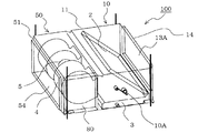
図1は、実施の形態に係る空気調和装置の室内機100の模式図である。図2は、図1に示す送風機ユニット50と熱交換器ユニット10との連結状態を変化させた状態の断面図である。図3は、図1に示す室内機100のドレンパン3の斜視図である。図4は、実施の形態に係る室内機100の分解斜視図である。図1〜図4を参照して、空気調和装置の室内機100の構成について説明する。
なお、図2は、図1に示す送風機ユニット50の上下を反転させ、図1に示す熱交換器ユニット10の上下を反転させないで前後のみ反転させた状態の断面図である。以下の説明において、図1の送風機ユニット50と送風機ユニット50との連結状態を連結状態Aと称し、図3の連結状態を連結状態Bと称する。また、以下の図面では、各構成の大きさや形状が一部異なる場合がある。
本実施の形態に係る室内機100は、コストアップの抑制、部品点数増加の抑制、本体重量増加の抑制、冷媒漏れリスクの低減及び空調性能低下の抑制などを実現しながら、室内機100に接続される配管の取り出し位置の変更を容易とする改良が加えられたものである。
Hereinafter, embodiments of the present invention will be described with reference to the drawings.
Embodiment.
2 is a cross-sectional view showing a state where the
The
[構成説明]
室内機100は、蒸発器や凝縮器として機能する室内機側熱交換器2が設けられた熱交換器ユニット10と、室内機100内に空気を取り込んだ後に室内機100外に空気を放出する送風機4が設けられた送風機ユニット50とを有している。なお、図1及び図2の連結状態において、室内機100の熱交換器ユニット10と送風機ユニット50とが連結されている状態を図示しているが、熱交換器ユニット10と送風機ユニット50とは、分離することができるようになっている。室内機100は、図2に示すように、たとえば、天井裏(天井6の上面)に設置される天埋め型として利用される。
[Description of configuration]
The
(熱交換器ユニット10)
熱交換器ユニット10は、送風機ユニット50から空気が供給されるように送風機ユニット50と連結して設けられるものである。熱交換器ユニット10は、外郭として、略直方体であってそのうちの対向する2面が開放された筐体11を有している。
また、熱交換器ユニット10には、「送風機ユニット50から供給される空気と、図示省略の室外機から供給された冷媒とを熱交換させる室内機側熱交換器2」と、「室内機側熱交換器2で生成された結露水(ドレン水)を貯留するドレンパン3」とが筐体11に搭載されている。
さらに、送風機ユニット50は、上下を反転させることなく、前後を反転させて熱交換器ユニット10に連結させることができる。より詳細には、図1の連結状態Aから送風機ユニット50の前後を反転させると、後述の吹出口部14側が、送風機ユニット50側に連結されることとなる。なお、上下を反転させないようにしているのは、ドレンパン3の位置が室内機側熱交換器2の上側とならないようにするためである。
(Heat exchanger unit 10)
The
The
Further, the
(筐体11)
筐体11は、図4に示すように、熱交換器ユニット10の外郭を構成するものであり、送風機ユニット50側と、その反対側とが開放されている。すなわち、筐体11は、「送風機ユニット50側の側面を構成する連結側側面部12に形成された開口部13A」が形成され、「開口部13A側と対向するように形成され、筐体11内の空気を放出するための開口部13B」が形成され、「開口部13Aと開口部13Bとの間には、送風機ユニット50側から供給される空気が流れる風路13C」が形成されている。
また、筐体11には、「開口部13A及び開口部13Bのうち、送風機ユニット50側でない方に設けられる吹出口14部」が着脱自在に取り付けられ、「室内機側熱交換器2に接続される冷媒配管が筐体11内外を連通させるようにする配管引出部10A」が設けられている。
(Case 11)
As shown in FIG. 4, the
In addition, the
ここで、筐体11は、図1及び図4において、「開口部13A側」で送風機ユニット50と連結している状態を示しているが、「吹出口部14側」で送風機ユニット50に連結させることも可能となっている。すなわち、筐体11は、図1及び図4に示す状態から、上下を反転させないで前後を反転させて送風機ユニット50と連結させることができるようになっている。これにより、配管引出部10Aの位置が図1及び図4の紙面手前側から紙面奥側になり、配管の取り出し位置を変更することができる。
なお、図1に示す連結状態Aにおいて、開口部13Aは、熱交換器ユニット10の空気吸込側であり、開口部13Bは、熱交換器ユニット10の空気吹出側である。
一方、筐体11の上下を反転させないで前後を反転させた場合(連結状態B)には、開口部13Aは、熱交換器ユニット10の空気吹出側であり、開口部13Bは、熱交換器ユニット10の空気吸込側である。
Here, in FIG. 1 and FIG. 4, the
In the connection state A shown in FIG. 1, the opening 13 </ b> A is on the air suction side of the
On the other hand, when the front and rear of the
吹出口部14は、開口部13Bの形成位置に設けられ、筐体11から着脱自在である。これにより、筐体11の前後を反転させたときにおいても、送風機ユニット50に接続されていた側の開口部13Bに吹出口部14を取り付けることができる。
なお、吹出口部14の取付位置は、開口部13Aと対向する開口部13A側に設けられた場合を例に説明したがそれに限定されるものではない。たとえば、室内機100の底面側が開放されたような態様の場合には、筐体11の底面側に吹出口部14を設けてもよい。
The
In addition, although the attachment position of the
筐体11には、送風機ユニット50を上下反転させても設置を可能とする第1吊り下げ金具1Aが設けられている。第1吊り下げ金具1Aの設けられる位置は、筐体11の8つの頂点のうち、下側に位置する4つの頂点付近とするとよい。より詳細には、第1吊り下げ金具1Aの設けられる位置は、筐体11の下側であり、空気流れ方向の上流側の端部側及び下流側の端部側であり、空気流れ方向を正面としたときの幅方向の両端部側とするとよい。
The
(室内機側熱交換器2)
室内機側熱交換器2は、筐体11内に取り込まれた空気と、図示省略の室外機から供給される冷媒とを熱交換させるものであり、たとえば、複数平行に立設されたフィンと、当該フィンに接続され、冷媒が供給されるチューブとを有するフィンチューブ熱交換器などで構成するとよい。
室内機側熱交換器2は、筐体11の底面に対して傾斜した姿勢で、ドレンパン3上に支持されて設けられている。すなわち、室内機側熱交換器2は、図2に示す状態においては、送風機ユニット50側の端部側がドレンパン3に支持されている。
(Indoor unit side heat exchanger 2)
The indoor unit-
The indoor unit
より詳細には、室内機側熱交換器2は、図1及び図2の連結状態A及び連結状態Bにおいて、一方の端部側が送風機ユニット50側に位置し、他方の端部側が吹出口部14側に位置するように、筐体11の底面に対して傾斜して設けられている。
なお、連結状態Aのとき、室内機側熱交換器2は、一方の端部側よりも、他方の端部側の方が上側に位置するように、筐体11の底面に対して傾斜して設けられている。
また、連結状態Bのとき、熱交換器ユニット10は、他方の端部側よりも、一方の端部側の方が上側に位置するように、筐体11の底面に対して傾斜して設けられている。
More specifically, the indoor unit
In the connected state A, the indoor unit-
Further, in the connected state B, the
(ドレンパン3)
ドレンパン3は、室内機側熱交換器2を支持するとともに、室内機側熱交換器2から滴下するドレン水を貯留するものであり、たとえば、樹脂などを所定の形状に形成して構成されるものである。
ドレンパン3には、図3に示すように、ドレンパン3の一方の端部側であって紙面の手前側から奥行側に伸びるように形成された第1傾斜部aと、ドレンパン3の他方の端部側であって紙面の手前側から奥行側に伸びるように形成された第2傾斜部bとを有している。
なお、図1に示す送風機ユニット50と熱交換器ユニット10との連結状態Aにおいて、第1傾斜部aは送風機ユニット50側に位置しており、第2傾斜部bは吹出口部14側に位置している。一方、図2に示す送風機ユニット50と熱交換器ユニット10との連結状態Bにおいて、第1傾斜部aは熱交換器ユニット10側に位置しており、第2傾斜部bは送風機ユニット50側に位置している。
(Drain pan 3)
The
As shown in FIG. 3, the
In addition, in the connection state A of the
第1傾斜部a及び第2傾斜部bは、室内機側熱交換器2の傾斜方向とは逆方向に傾斜している。たとえば、図1では、室内機側熱交換器2が送風機ユニット50側から吹出口部14側に向かって下側に傾斜しているが、第1傾斜部a及び第2傾斜部bは、吹出口部14側から送風機ユニット50側に向かって下側に傾斜している。
このように、第1傾斜部aが形成されているため、図1の連結状態Aでは、第1傾斜部aが送風機4から吹き出される斜め上側方向の空気の流れを阻害することを抑制することができる。また、第2傾斜部bが形成されているため、図2の連結状態Bでは、第2傾斜部bが送風機4から吹き出される斜め下側方向の空気の流れを阻害することを抑制することができる。
The first inclined part a and the second inclined part b are inclined in a direction opposite to the inclination direction of the indoor unit
Thus, since the 1st inclination part a is formed, in the connection state A of FIG. 1, it suppresses that the 1st inclination part a inhibits the flow of the air of the diagonal upper direction which blows off from the
第2傾斜部bは、第2傾斜部bの頂部の高さ位置が第1傾斜部aよりも高くなるように形成されている。このため、ドレンパン3は、前側と後側の形状が異なることとなり、熱交換器ユニット10を前後反転させたときに圧損が生じて風量に差が生じる。そこで、吹出口部14が設けることで、この風量差を低減し、前後反転させても空調能力が安定するようにしている。この点については、後述の[吹出口部14の詳細な構成]で説明する。
The 2nd inclination part b is formed so that the height position of the top part of the 2nd inclination part b may become higher than the 1st inclination part a. For this reason, the
(送風機ユニット50)
送風機ユニット50は、送風機ユニット50の外郭である筐体51と、筐体51内に設けられた送風機4とを有しており、筐体51内に空気を取り込んだ後に熱交換器ユニット10に供給するものである。送風機ユニット50は、送風機ユニット50と連結して設けられる。なお、この送風機ユニット50は、上下を反転させて熱交換器ユニット10に連結させることができる。
送風機ユニット50は、外郭として、略直方体であってそのうちの対向する2面が開放された形状の筐体51を有している。
(Blower unit 50)
The
The
(筐体51)
筐体51は、図4に示すように、送風機4を収容するものであり、熱交換器ユニット10側と、その反対側とが開放されている。すなわち、筐体51は、「送風機ユニット50側の側面を構成する連結側側面部52に形成された吹出口55(図5参照)」と、「吹出口55側の対向側に形成され、筐体51内に空気を取り込むための吸込口54」とを有している。
また、筐体51には、2台の送風機4が、空気流れ方向とは略垂直な方向に並ぶようにして設けられている。なお、送風機4の台数は、2台に限定されるものではない。
ここで、筐体51は、図1、図2及び図4において、「連結側側面部52側と、熱交換器ユニット10の連結側側面部12側と」が連結している状態を示しているが、熱交換器ユニット10の前後を反転させた際には、「連結側側面部52側と、熱交換器ユニット10の吹出口部14側と」が連結する。
(Case 51)
As shown in FIG. 4, the
The
Here, the
筐体51は、上下を反転させて、送風機ユニット50に連結させることが可能となっている。すなわち、筐体51は、図1及び図2に示す筐体51の底面と、上面とが反転とした状態においても、熱交換器ユニット10に連結させることができる。なお、図1及び図2に示す筐体51の上下を反転にした場合には、熱交換器ユニット10が、上下を反転させないで前後を反転させた状態で連結される。これにより、室内機側熱交換器2に供給される風量が低減してしまうことを抑制することができる。なお、この風量の低減の抑制については、後述の図8〜図10で説明する。
The
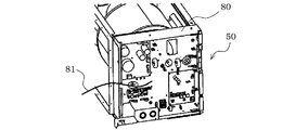
筐体51には、略直方体形状をしており、送風機ユニット50の連結側側面部52と直交する側面に沿って設けられる電気品箱80が固定されている。
より詳細には、電気品箱80は、筐体51のうち吸込口54が形成された面及び連結側側面部52が形成された面と直交する側面に設けられている。このように、筐体51の上下を反転したとしても電気品箱80の位置がそれほど変化しないように、真横からの配線引き込みとしている(図6参照)。これにより、配線81の長さを調整するなどの作業負担を軽減することができる。
The
More specifically, the
筐体51には、送風機ユニット50を前後反転させても筐体51を吊り下げて固定することを可能とする第2吊り下げ金具1Bが設けられている。第2吊り下げ金具1Bの設けられる位置は、筐体51の8つの頂点のうち、上流側に位置する4つの頂点付近とするとよい。より詳細には、第2吊り下げ金具1Bの設けられる位置は、筐体51の上側であり、空気流れ方向の上流側であり、空気流れ方向を正面としたときの幅方向の端部側とするとよい。
The
(送風機4)
送風機4は、たとえばシロッコファンなどで構成されるものであり、吸込口54から取り込んだ空気を、熱交換器ユニット10側に供給するものである。送風機4は、図示省略の回転する羽根と、この羽根を回転させるモーター5とを有している。このモーター5は、電気品箱80内に設けられた制御装置などに接続されている。また、送風機4は、図3に示すように、空気の吹出部4Aを有している。
(Blower 4)
The
図1に示す連結状態Aでは、この吹出部4Aから吹き出される空気の流れが、上側、より詳細には斜め上側となるように送風機ユニット50と熱交換器ユニット10とが連結している。
一方、図2に示す連結状態Bでは、図1の連結状態Aから送風機ユニット50の上下を反転させたため、吹出部4Aから吹き出される空気の流れが、下側、より詳細には斜め下側となるように送風機ユニット50と熱交換器ユニット10とが連結している。
In the connection state A shown in FIG. 1, the
On the other hand, in the connection state B shown in FIG. 2, since the upper and lower sides of the
[送風機ユニット50の吹出口55及び電気品箱80について]
図5は、実施の形態に係る送風機ユニット50の斜視図である。図6は、電気品箱80の斜視図である。図5及び図6を参照して、送風機ユニット50に形成された吹出口55及び電気品箱80から引き出される配線81について説明する。
図5に示すように、送風機ユニット50には、吹出口55が2つ併設されている。この吹出口55は、送風機4の吹出部4Aと連通するように形成されている。この吹出口55から吹き出された空気は、熱交換器ユニット10側へ供給される。
[About the
FIG. 5 is a perspective view of the
As shown in FIG. 5, the
また、電気品箱80については、送風機4の側方に設けられている。このため、送風機ユニット50の上下の反転をした後であっても、配線81によって接続されるもの同士の位置が変化してしまわないようにすることができ、別途配線を交換する必要などがない。
Further, the
[吹出口部14の詳細な構成]
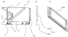
図7は、室内機100の吹出口部14の付近の説明図である。図7を参照して、吹出口部14の詳細な構成について説明する。なお図7(a)は、吹出口部14が熱交換器ユニット10に取り付けられた状態の図であり、図7(b)は、吹出口部14を側方から見た図であり、図7(c)は、開放部14Aの斜視図である。
吹出口部14は、筐体11から分離可能であり、開口部13A及び開口部13Bのうちの前方側の開口部に取り付けることができるようになっている。吹出口部14は、空気が連通する開放部14Aと、空気の流れを閉塞する閉塞部14Bとから構成されている。
開放部14Aは、その下端側の高さ位置が、ドレンパン3の第2傾斜部bの頂部の高さ位置と略同一となるように形成されている。また、開放部14Aは、平面視形状が略長方形であり、空気流れ方向に対して略平行に突出するように吹出口部14に形成されている。
閉塞部14Bは、空気流れ方向に対して略直交するように設けられる平板状部材であり、ドレンパン3の第1傾斜部a、又は、第2傾斜部bに対向するように設けられる。閉塞部14Bは、その高さ方向の幅が第1傾斜部aよりも大きく、第2傾斜部bと略同一となっている。
[Detailed configuration of the outlet 14]
FIG. 7 is an explanatory diagram of the vicinity of the
The
The opening
The closing
仮に、室内機100にこの吹出口部14が設けられていないと、連結状態Aのときよりも連結状態Bのときの方が、空気の吹出面が大きくなってしまい、連結状態の変更前後で同様の風量を確保することができない。
しかしながら、室内機100は、この吹出口部14が設けられることにより、連結状態Aであっても連結状態Bであっても、空気の吹出面の面積が開放部14Aとなる。すなわち、熱交換器ユニット10を前後に反転させたときでも、変更前と同様の風量を確保し、空調性能の低下を抑制することができる。
If the
However, the
[連結状態A及び連結状態Bについて]
図8は、実施の形態に係る室内機100の配管取出し方向の説明図である。なお、この図8の説明では、図8(a)の連結状態から、図8(b)の連結状態に変化させた場合を例に説明する。
図8(a)の変更前においては、送風機ユニット50から放出される空気が上側に向くように、送風機ユニット50と熱交換器ユニット10とが連結される。また、変更前においては、室内機側熱交換器2の上端部側が送風機ユニット50側にくるように、送風機ユニット50と熱交換器ユニット10とが連結される。なお、図8(a)の状態においては、配管引出部10Aが紙面の手前側の側面に位置している。
[About connected state A and connected state B]
FIG. 8 is an explanatory diagram of the pipe take-out direction of the
Before the change of FIG. 8A, the
図8(b)の変更後においては、送風機ユニット50から放出される空気が下側に向くように、送風機ユニット50と熱交換器ユニット10とが連結される。また、変更後においては、室内機側熱交換器2の下端部側が送風機ユニット50側にくるように、送風機ユニット50と熱交換器ユニット10とが連結される。なお、図8(b)の状態においては、配管引出部10Aが紙面の奥側の側面に位置している。
After the change in FIG. 8B, the
このように、室内機100は、送風機ユニット50が上下に反転可能であり、熱交換器ユニット10が上下を反転させないで前後を反転可能となっており、配管引出部10Aの位置を変更することができるようになっている。これにより、コストアップの抑制、部品点数増加の抑制、室内機100の重量増加の抑制、冷媒漏れリスクの低減及び空調性能低下の抑制などを実現しながら、室内機100に接続される配管の取り出し位置の変更が容易となっている。
Thus, in the
[連結状態Aの効果について]
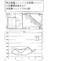
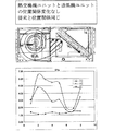
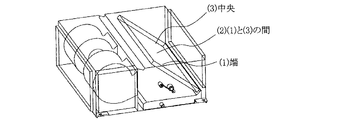
図9は、図1に示す室内機100の状態から送風機ユニット50を上下反転させた場合の室内機側熱交換器2に供給される風量の説明図である。図10は、図1に示す室内機100の室内機側熱交換器2に供給される風量の説明図である。図11は、図9及び図10に示す(1)〜(3)のグラフが室内機側熱交換器2のどの位置に対応する結果であるかを説明する図である。
なお、図9及び図10の縦軸は風量(m/s)を示し、横軸は室内機側熱交換器2のうちの送風機ユニット50側の端部から吹出口部14側の端部にかけての位置に対応している。
また、図10は、連結状態A(図8(a)に対応)であるが、図9は、連結状態A及び連結状態Bのいずれにも該当しない連結状態である。
[About the effect of connected state A]
FIG. 9 is an explanatory diagram of the amount of air supplied to the indoor unit
9 and 10, the vertical axis represents the air volume (m / s), and the horizontal axis from the end on the
FIG. 10 shows a connection state A (corresponding to FIG. 8A), but FIG. 9 shows a connection state that does not correspond to either the connection state A or the connection state B.
図9に示すように、室内機側熱交換器2の「(1)端」、「(3)中央」及び「(2)(1)と(3)との間」のいずれにおいても、風速が3(m/s)に満たないことがわかる。すなわち、図9の連結状態においては、充分な空調能力を確保することができないことがわかる。これは、送風機4から吹き出された空気の流れ方向と、室内機側熱交換器2とが形成する角度が小さくなっているためである。
As shown in FIG. 9, the wind speed is “(1) end”, “(3) center” and “between (2) (1) and (3)” of the indoor unit
一方、図10に示す連結状態Aでは、室内機側熱交換器2の「(1)端」、「(3)中央」及び「(2)(1)と(3)との間」のいずれにおいても、図9の連結状態の風量特性が向上している。特に、「(2)(1)と(3)との間」の風量については、5(m/s)に近い値を確保でき、「(3)中央」の風量については、7(m/s)に近い値を確保できる。また、「(1)端」においても、概ね図9の「(1)端」よりも高い風量となっている。これは、送風機4から吹き出された空気の流れ方向と、室内機側熱交換器2とが形成する角度が、垂直に近い角度となっているためである。
On the other hand, in the connection state A shown in FIG. 10, any one of “(1) end”, “(3) center” and “between (2) (1) and (3)” of the indoor unit
[実施の形態に係る室内機100の有する効果]
実施の形態に係る室内機100は、連結状態A及び連結状態Bを有する熱交換器ユニット10と送風機ユニット50を備えたので、配管を引き回したり、別途新たな配管を追加したりすることが不要となり、コストアップの抑制、部品点数増加の抑制、本体重量増加の抑制、冷媒漏れリスクの低減及び空調性能低下の抑制などを実現しながら、配管引出部10Aの位置を容易に変更することができる。
[Effects of
Since the
また、たとえば性能の良い送風機ユニットや熱交換器ユニットがある場合には、送風機ユニット及び熱交換器ユニットのうちのいずれか一方を単独で交換することを容易にすることができる。すなわち、室内機100は、スペック変更が容易となっている。
Further, for example, when there is a fan unit or a heat exchanger unit with good performance, it is possible to easily replace any one of the fan unit and the heat exchanger unit. That is, the specification change of the
1A 第1吊り下げ金具、1B 第2吊り下げ金具、2 室内機側熱交換器、3 ドレンパン、4 送風機、4A 吹出部、5 モーター、6 天井、10 熱交換器ユニット(第2のユニット)、10A 配管引出部、11 筐体、12 連結側側面部、13A 開口部、13B 開口部、13C 風路、14 吹出口部、14A 開放部、14B 閉塞部、50 送風機ユニット(第1のユニット)、51 筐体、52 連結側側面部、54 吸込口、55 吹出口、80 電気品箱、81 配線、100 室内機、a 第1傾斜部、b 第2傾斜部。
1A 1st hanging bracket, 1B 2nd hanging bracket, 2 indoor unit side heat exchanger, 3 drain pan, 4 blower, 4A outlet, 5 motor, 6 ceiling, 10 heat exchanger unit (second unit), 10A Pipe extraction part, 11 Housing, 12 Connection side surface part, 13A opening part, 13B opening part, 13C Air passage, 14 Air outlet part, 14A Opening part, 14B Closure part, 50 Blower unit (first unit), DESCRIPTION OF
Claims (8)
対向位置に一対の開口部が形成され、室内機側熱交換器が収容された熱交換器ユニットと、
を有し、
前記熱交換器ユニットは、
当該熱交換器ユニットの底面及び上面の関係を維持した状態で前後に反転させて、前記一対の開口部が選択的に前記送風機ユニットの前記吹出口に接続可能であり、
前記送風機ユニットは、
前記吹出口が前記熱交換器ユニットの前記一対の開口部のうちの選択された方の開口部に、上下に反転させて接続可能である
ことを特徴とする空気調和装置の室内機。 A blower unit having a suction port and a blower outlet, in which the blower is stored;
A heat exchanger unit in which a pair of openings are formed at the opposed positions and the indoor unit side heat exchanger is accommodated, and
Have
The heat exchanger unit is
The pair of openings can be selectively connected to the outlet of the blower unit by inverting the front and back while maintaining the relationship between the bottom and top surfaces of the heat exchanger unit,
The blower unit is
The indoor unit of an air conditioner, wherein the air outlet is connectable by being inverted upside down to a selected one of the pair of openings of the heat exchanger unit.
当該送風機ユニットの上面側及び下面側に、当該送風機ユニットを据え付ける際に利用される第1吊り下げ金具が設けられ、
前記熱交換器ユニットには、
前記一対の開口部が形成されている端部側に、前記熱交換器ユニットを据え付ける際に利用される第2吊り下げ金具が設けられた
ことを特徴とする請求項1に記載の空気調和装置の室内機。 In the blower unit,
On the upper surface side and the lower surface side of the blower unit, a first hanging bracket used when installing the blower unit is provided,
The heat exchanger unit includes
2. The air conditioner according to claim 1, wherein a second hanging metal fitting used when installing the heat exchanger unit is provided on an end portion side where the pair of openings are formed. Indoor unit.
前記熱交換器ユニットの一方の前記開口部側から他方の前記開口部側に向かって傾斜するように設置された
ことを特徴とする請求項1又は2に記載の空気調和装置の室内機。 The indoor unit side heat exchanger is
The indoor unit of an air conditioner according to claim 1 or 2, wherein the indoor unit is installed so as to be inclined from one opening side of the heat exchanger unit toward the other opening side.
前記室内機側熱交換器の一方の端部側を支持するように、前記室内機側熱交換器の下側に設けられたドレンパンを有する
ことを特徴とする請求項3に記載の空気調和装置の室内機。 The heat exchanger unit is
The air conditioner according to claim 3, further comprising a drain pan provided below the indoor unit side heat exchanger so as to support one end side of the indoor unit side heat exchanger. Indoor unit.
前記室内機側熱交換器の接触位置に第1傾斜面が形成され、当該第1傾斜面の対向側に第2傾斜面が形成され、
前記第1傾斜面及び前記第2傾斜面は、
前記室内機側熱交換器の傾斜する方向と逆方向に傾斜している
ことを特徴とする請求項4に記載の空気調和装置の室内機。 In the drain pan,
A first inclined surface is formed at the contact position of the indoor unit side heat exchanger, and a second inclined surface is formed on the opposite side of the first inclined surface,
The first inclined surface and the second inclined surface are:
The indoor unit of an air conditioner according to claim 4, wherein the indoor unit side heat exchanger is inclined in a direction opposite to a direction in which the indoor unit side heat exchanger is inclined.
前記吹出口部は、
前記ドレンパンの前記第1傾斜面及び前記第2傾斜面のうち高さ位置の高い方の傾斜面より上側が開放され、
前記ドレンパンの前記第1傾斜面及び前記第2傾斜面のうち高さ位置の高い方の傾斜面より下側が閉塞されている
ことを特徴とする請求項5に記載の空気調和装置の室内機。 Of the pair of openings formed in the heat exchanger unit, having an air outlet portion separable into an opening functioning as an air outlet,
The air outlet is
The upper side of the first inclined surface and the second inclined surface of the drain pan is opened above the inclined surface having the higher height position,
The indoor unit of the air conditioner according to claim 5, wherein a lower side of the first inclined surface and the second inclined surface of the drain pan is blocked from an inclined surface having a higher height position.
前記送風機ユニットの側面に前記送風機を制御する電気品箱が設けられた
ことを特徴とする請求項1〜6のいずれか一項に記載の空気調和装置の室内機。 In the blower unit,
The indoor unit of the air conditioner according to any one of claims 1 to 6, wherein an electrical component box for controlling the blower is provided on a side surface of the blower unit.
熱交換器を収容した第2のユニットとを備え、
第2のユニット内には、
前記送風機から送られた風が横断する風路と、
複数のフィンと冷媒流路からなる熱交換器と、
熱交換器と外部機器との間で冷媒を循環させるための冷媒配管の一部と、
熱交換器に結露し滴下する結露水を受けるドレンパンを有すると共に、
前記熱交換器は、
風流に対して傾斜して配置されており、
前記第2のユニットを前後反転可能、前記第1のユニットを上下反転可能に、第1のユニットと第2のユニットとを接続する
ことを特徴とする空気調和装置の室内機。 A first unit containing a blower;
A second unit containing a heat exchanger,
In the second unit,
An air path traversed by the wind sent from the blower;
A heat exchanger comprising a plurality of fins and a refrigerant flow path;
A part of the refrigerant pipe for circulating the refrigerant between the heat exchanger and the external device;
It has a drain pan that receives the condensed water that is condensed and dripped onto the heat exchanger,
The heat exchanger is
It is arranged to be inclined with respect to the wind flow,
An indoor unit of an air conditioner, wherein the first unit and the second unit are connected such that the second unit can be reversed upside down and the first unit can be turned upside down.
Priority Applications (2)
| Application Number | Priority Date | Filing Date | Title |
|---|---|---|---|
| JP2012140044A JP2014005954A (en) | 2012-06-21 | 2012-06-21 | Indoor equipment of air-conditioning device |
| US13/710,510 US20130340972A1 (en) | 2012-06-21 | 2012-12-11 | Indoor unit of air-conditioning apparatus |
Applications Claiming Priority (1)
| Application Number | Priority Date | Filing Date | Title |
|---|---|---|---|
| JP2012140044A JP2014005954A (en) | 2012-06-21 | 2012-06-21 | Indoor equipment of air-conditioning device |
Publications (1)
| Publication Number | Publication Date |
|---|---|
| JP2014005954A true JP2014005954A (en) | 2014-01-16 |
Family
ID=49773411
Family Applications (1)
| Application Number | Title | Priority Date | Filing Date |
|---|---|---|---|
| JP2012140044A Pending JP2014005954A (en) | 2012-06-21 | 2012-06-21 | Indoor equipment of air-conditioning device |
Country Status (2)
| Country | Link |
|---|---|
| US (1) | US20130340972A1 (en) |
| JP (1) | JP2014005954A (en) |
Cited By (2)
| Publication number | Priority date | Publication date | Assignee | Title |
|---|---|---|---|---|
| WO2017203702A1 (en) * | 2016-05-27 | 2017-11-30 | 三菱電機株式会社 | Air conditioning device |
| JP2017214900A (en) * | 2016-06-01 | 2017-12-07 | 三菱電機株式会社 | Air blowing device and air conditioning device including the same |
Families Citing this family (5)
| Publication number | Priority date | Publication date | Assignee | Title |
|---|---|---|---|---|
| CN204460456U (en) * | 2014-07-03 | 2015-07-08 | 青岛海尔空调器有限总公司 | A kind of dehydrating unit and air treatment system |
| CN105588196A (en) * | 2015-12-03 | 2016-05-18 | 青岛海信日立空调系统有限公司 | Indoor unit of air conditioner |
| US10865798B2 (en) * | 2016-05-30 | 2020-12-15 | Zhongshan Broad-Ocean Motor Co., Ltd. | Fan coil unit |
| CN107957129B (en) * | 2017-11-29 | 2020-06-09 | 海信(山东)空调有限公司 | Spacing cardboard of tuber pipe machine water collector and tuber pipe machine |
| WO2020218059A1 (en) * | 2019-04-25 | 2020-10-29 | 日本電気株式会社 | Local cooling device and local cooling method |
Citations (9)
| Publication number | Priority date | Publication date | Assignee | Title |
|---|---|---|---|---|
| US3012762A (en) * | 1958-08-18 | 1961-12-12 | Lennox Ind Inc | Modular units for air heating, cooling and ventilating systems |
| JPS62293028A (en) * | 1986-06-10 | 1987-12-19 | Hitachi Ltd | Drain pan for air conditioner |
| JPH0658564A (en) * | 1992-08-07 | 1994-03-01 | Daikin Ind Ltd | Air conditioner |
| JPH10176840A (en) * | 1996-12-17 | 1998-06-30 | Mitsubishi Electric Corp | Air conditioner |
| JP2001227771A (en) * | 2000-02-18 | 2001-08-24 | Fujitsu General Ltd | Air conditioner |
| JP2001304610A (en) * | 2000-02-14 | 2001-10-31 | Mitsubishi Electric Corp | Air conditioner |
| JP2006343021A (en) * | 2005-06-08 | 2006-12-21 | Shimizu Corp | Installation structure for fan coil unit |
| JP2008261541A (en) * | 2007-04-11 | 2008-10-30 | Kimura Kohki Co Ltd | Ceiling-installation type fan coil unit |
| JP2011158187A (en) * | 2010-02-01 | 2011-08-18 | Mitsubishi Electric Corp | Indoor unit for air conditioner |
Family Cites Families (6)
| Publication number | Priority date | Publication date | Assignee | Title |
|---|---|---|---|---|
| US2282373A (en) * | 1938-12-01 | 1942-05-12 | Westinghouse Electric & Mfg Co | Air conditioning apparatus |
| US3985295A (en) * | 1975-03-17 | 1976-10-12 | Monninger Robert C | Heat collector and diffuser |
| US4088466A (en) * | 1976-09-30 | 1978-05-09 | Westinghouse Electric Corp. | Multi-position air conditioning unit |
| US4129013A (en) * | 1977-09-01 | 1978-12-12 | Westinghouse Electric Corp. | Air-conditioning unit with multi-position coil |
| US4410033A (en) * | 1981-07-02 | 1983-10-18 | Carrier Corporation | Combination coupling retainer and support for a heat exchange unit |
| US5904053A (en) * | 1996-12-11 | 1999-05-18 | International Comfort Products | Drainage management system for refrigeration coil |
-
2012
- 2012-06-21 JP JP2012140044A patent/JP2014005954A/en active Pending
- 2012-12-11 US US13/710,510 patent/US20130340972A1/en not_active Abandoned
Patent Citations (9)
| Publication number | Priority date | Publication date | Assignee | Title |
|---|---|---|---|---|
| US3012762A (en) * | 1958-08-18 | 1961-12-12 | Lennox Ind Inc | Modular units for air heating, cooling and ventilating systems |
| JPS62293028A (en) * | 1986-06-10 | 1987-12-19 | Hitachi Ltd | Drain pan for air conditioner |
| JPH0658564A (en) * | 1992-08-07 | 1994-03-01 | Daikin Ind Ltd | Air conditioner |
| JPH10176840A (en) * | 1996-12-17 | 1998-06-30 | Mitsubishi Electric Corp | Air conditioner |
| JP2001304610A (en) * | 2000-02-14 | 2001-10-31 | Mitsubishi Electric Corp | Air conditioner |
| JP2001227771A (en) * | 2000-02-18 | 2001-08-24 | Fujitsu General Ltd | Air conditioner |
| JP2006343021A (en) * | 2005-06-08 | 2006-12-21 | Shimizu Corp | Installation structure for fan coil unit |
| JP2008261541A (en) * | 2007-04-11 | 2008-10-30 | Kimura Kohki Co Ltd | Ceiling-installation type fan coil unit |
| JP2011158187A (en) * | 2010-02-01 | 2011-08-18 | Mitsubishi Electric Corp | Indoor unit for air conditioner |
Cited By (2)
| Publication number | Priority date | Publication date | Assignee | Title |
|---|---|---|---|---|
| WO2017203702A1 (en) * | 2016-05-27 | 2017-11-30 | 三菱電機株式会社 | Air conditioning device |
| JP2017214900A (en) * | 2016-06-01 | 2017-12-07 | 三菱電機株式会社 | Air blowing device and air conditioning device including the same |
Also Published As
| Publication number | Publication date |
|---|---|
| US20130340972A1 (en) | 2013-12-26 |
Similar Documents
| Publication | Publication Date | Title |
|---|---|---|
| JP2014005954A (en) | Indoor equipment of air-conditioning device | |
| AU2018330131B2 (en) | Ceiling-type indoor unit of air conditioner | |
| JP5587060B2 (en) | Built-in air conditioner | |
| JP6800339B2 (en) | How to install the indoor unit of the air conditioner, the indoor unit of the air conditioner and the indoor unit of the air conditioner | |
| JP6038328B2 (en) | Air conditioner indoor unit | |
| JP2019178835A (en) | Ceiling embedded type air conditioner | |
| JP2008045780A (en) | Indoor unit of air conditioner | |
| JP6508465B2 (en) | Duct type air conditioner | |
| JP6468303B2 (en) | Air conditioner indoor unit | |
| JP6126447B2 (en) | Air conditioner | |
| JP2017053559A (en) | Indoor unit of air conditioner | |
| JP2019178825A (en) | Ceiling embedded type air conditioner | |
| JP5860752B2 (en) | Air conditioner | |
| JP2016070614A (en) | Ceiling embedded type air conditioner | |
| JP6384244B2 (en) | Embedded ceiling air conditioner | |
| JP6331935B2 (en) | Embedded ceiling air conditioner | |
| JP2005195199A (en) | Air-conditioner | |
| JP2016099034A (en) | Air conditioning device, adjustment method of air conditioning device and manufacturing method of air conditioning facility | |
| JP2018059641A (en) | Indoor machine of air conditioner | |
| JP4425007B2 (en) | Ventilation unit | |
| JP6375837B2 (en) | Embedded ceiling air conditioner | |
| JP2013029224A (en) | Indoor unit of ceiling-embedded air conditioning device | |
| WO2020203987A1 (en) | Indoor unit for air conditioner | |
| JP2012032035A (en) | Air conditioner | |
| JP2016153703A (en) | Air conditioner |
Legal Events
| Date | Code | Title | Description |
|---|---|---|---|
| A621 | Written request for application examination |
Free format text: JAPANESE INTERMEDIATE CODE: A621 Effective date: 20150202 |
|
| A977 | Report on retrieval |
Free format text: JAPANESE INTERMEDIATE CODE: A971007 Effective date: 20160217 |
|
| A131 | Notification of reasons for refusal |
Free format text: JAPANESE INTERMEDIATE CODE: A131 Effective date: 20160223 |
|
| A521 | Request for written amendment filed |
Free format text: JAPANESE INTERMEDIATE CODE: A523 Effective date: 20160411 |
|
| A02 | Decision of refusal |
Free format text: JAPANESE INTERMEDIATE CODE: A02 Effective date: 20160719 |