JP2014201214A - Instrument for vehicle - Google Patents
Instrument for vehicle Download PDFInfo
- Publication number
- JP2014201214A JP2014201214A JP2013079211A JP2013079211A JP2014201214A JP 2014201214 A JP2014201214 A JP 2014201214A JP 2013079211 A JP2013079211 A JP 2013079211A JP 2013079211 A JP2013079211 A JP 2013079211A JP 2014201214 A JP2014201214 A JP 2014201214A
- Authority
- JP
- Japan
- Prior art keywords
- vehicle
- sound
- case
- instrument
- display
- Prior art date
- Legal status (The legal status is an assumption and is not a legal conclusion. Google has not performed a legal analysis and makes no representation as to the accuracy of the status listed.)
- Pending
Links
- 239000004973 liquid crystal related substance Substances 0.000 description 6
- 239000000463 material Substances 0.000 description 2
- 229920005989 resin Polymers 0.000 description 2
- 239000011347 resin Substances 0.000 description 2
- 229920003002 synthetic resin Polymers 0.000 description 2
- 239000000057 synthetic resin Substances 0.000 description 2
- 230000005540 biological transmission Effects 0.000 description 1
- 230000000052 comparative effect Effects 0.000 description 1
- 238000010276 construction Methods 0.000 description 1
- 239000011521 glass Substances 0.000 description 1
- 239000000203 mixture Substances 0.000 description 1
- 238000000465 moulding Methods 0.000 description 1
- 125000006850 spacer group Chemical group 0.000 description 1
- 239000000758 substrate Substances 0.000 description 1
- 230000000007 visual effect Effects 0.000 description 1
Images

Classifications
-
- G—PHYSICS
- G01—MEASURING; TESTING
- G01D—MEASURING NOT SPECIALLY ADAPTED FOR A SPECIFIC VARIABLE; ARRANGEMENTS FOR MEASURING TWO OR MORE VARIABLES NOT COVERED IN A SINGLE OTHER SUBCLASS; TARIFF METERING APPARATUS; MEASURING OR TESTING NOT OTHERWISE PROVIDED FOR
- G01D7/00—Indicating measured values
- G01D7/12—Audible indication of meter readings, e.g. for the blind
-
- B60K35/26—
-
- B60K35/60—
-
- B60K35/80—
-
- B60K35/85—
-
- B60K2360/42—
-
- B60K2360/573—
-
- B60K2360/586—
Abstract
Description
本発明は、スピーカもしくはブザー等を用いて利用者に各種情報を提供する車両用計器に関する。 The present invention relates to a vehicular instrument that provides various types of information to a user using a speaker or a buzzer.
例えば、車両用計器においては、指針やインジケータを備えて利用者に対して情報を表示している。この車両用計器は、指針を回動させるムーブメント(例えば、モータ)やインジケータの光源(例えば、発光ダイオード)が搭載され、これらを駆動する電気回路が構成された回路基板を備えている。 For example, in a vehicle meter, information is displayed to a user with a pointer and an indicator. This vehicle instrument is equipped with a circuit board on which a movement (for example, a motor) for rotating a pointer and a light source for an indicator (for example, a light emitting diode) are mounted and an electric circuit for driving them is configured.
さらに、上述の指針やインジケータのような視覚性表示に加えて、ブザー等の発振部材(発音手段)を用いて音により車両の状態を利用者に認知せしめることも行われており、例えば、特許文献1に開示されている。この場合、発振部材は、電気接続の利便性や利用者との距離等を考慮して、前述の回路基板に実装されている。
Furthermore, in addition to the visual indications such as the above-mentioned pointers and indicators, the user can recognize the state of the vehicle by sound using an oscillating member (sounding means) such as a buzzer. It is disclosed in
また、発振部材によって、シートベルト装着情報やドア開状態の走行など各種警報音を出力でき、この警報音は、回路基板の背後を覆うカバーに設けた複数のスリットを通って、前記車両用計器の背後に伝えられ、その後、前記車両用計器を収納するインストルメントパネル内部から利用者側に伝わるようになっていた。 Further, the oscillating member can output various alarm sounds such as seat belt wearing information and door open state travel, and the alarm sound passes through a plurality of slits provided in a cover covering the back of the circuit board, and the vehicle instrument Then, it is transmitted from the inside of the instrument panel that houses the vehicle instrument to the user side.
しかしながら、車両用計器の中央には、指針駆動用のムーブメントや液晶表示パネルなどの表示器が設けられるケースが多く、また、回路基板を介して、他の電子部品に伝わる振動などを鑑みて、発振部材を回路基板の左右何れかに一つ設けることが一般的である。そのため、車両用計器を車両に組み付けた状態で、左右何れか一方側から聞こえるように感じてしまう場合があり、車両利用者に違和感を与えてしまう虞があった。 However, in the center of the vehicle meter, there are many cases where a display for driving a pointer or a liquid crystal display panel is provided, and in view of vibrations transmitted to other electronic components via the circuit board, Generally, one oscillating member is provided on either the left or right side of the circuit board. For this reason, in a state where the vehicle instrument is assembled to the vehicle, there may be a case where the user feels audible from either the left or right side, which may give a sense of discomfort to the vehicle user.
そこで本発明の目的は、上述した課題に着目して、音の指向性を改善することによって、車両利用者にとって聞き取りやすい音を発することができる車両用計器を提供することにある。 Accordingly, an object of the present invention is to provide a vehicle instrument that can emit a sound that is easy to hear for a vehicle user by improving the sound directivity by paying attention to the above-described problems.
本発明の車両用計器は、発音手段と、車両情報に応じて警報状態の際に前記発音手段の作動を制御する制御手段と、前記発音手段や前記制御手段を収納するケースと、を備えた車両用計器であって、この車両用計器が車両に組み付け状態における前記ケース内の左右いずれかに、前記発音手段を設け、前記ケースには、前記発音手段に対向し、この発音手段からの音を前記ケースの左右の両側へ反射可能な反射面を形成し、この反射面は、左右異なる面積で形成されることを特徴とする車両用計器。 The vehicle instrument of the present invention includes sound generation means, control means for controlling the operation of the sound generation means in an alarm state according to vehicle information, and a case for housing the sound generation means and the control means. An instrument for a vehicle, wherein the sounding means is provided on either the left or right side of the case when the vehicle instrument is assembled to a vehicle, and the case is opposed to the sounding means, and the sound from the sounding means is provided. The vehicle instrument is characterized in that a reflective surface that can be reflected to both the left and right sides of the case is formed, and the reflective surface is formed with different areas on the left and right.
また、前記車両情報を表示する表示器を備え、前記発音手段及び前記反射面は、前記表示器の背面側に設けられることを特徴とする。 In addition, a display device for displaying the vehicle information is provided, and the sound generation means and the reflection surface are provided on the back side of the display device.
本発明は、スピーカもしくはブザー等を用いて利用者に各種情報を提供する車両用計器に関し、音の指向性を改善することによって、車両利用者にとって聞き取りやすい音を発することができる車両用計器を提供することにある。 The present invention relates to a vehicular instrument that provides various information to a user using a speaker or a buzzer, etc., and relates to a vehicular instrument that can emit a sound that is easy to hear for a vehicle user by improving sound directivity. It is to provide.
以下、本発明の車両用計器を実施の形態として、自動車に搭載される車両用計器に適用したものを例にあげ、添付した図面に基づいて説明する。 DESCRIPTION OF THE PREFERRED EMBODIMENTS Hereinafter, a vehicle instrument according to the present invention will be described as an embodiment with reference to the accompanying drawings, taking as an example a vehicle instrument mounted on an automobile.
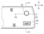
図1は、車両用計器Aの筐体内に収納される主要部品を示し、表示器1と、回路基板2と、保持部材3と、第1のケース(ケース)4と、第2のケース(ケース)5とを備え、インストルメントパネルPの開口箇所に設けられる。なお、図1は、図2のF1−F1断面を示す。
FIG. 1 shows the main components housed in the housing of the vehicle meter A. The
表示器1は、走行速度や積算走行距離などの車両情報を数値や、文字などの表示像を形成し、第1のケース4の窓部を介して表示出力できる。表示器1は、透明電極を有する一対のガラス基板間に液晶を封入し、前後側に設けられる偏光膜によって構成される液晶表示素子を設けており、該透明電極を介して駆動電力が供給されるようにしている。なお、表示器1は、夜間等の暗い環境においても利用者が視認できるように、図示しないバックライトによって該液晶表示素子を透過照明できるようにしている。
The
回路基板2は、マイクロコンピュータや描画処理回路など、車両用計器A外からの信号を入力し、表示器1の液晶表示素子や光源を駆動するための制御手段(電子部品)21が実装されている。なお、回路基板2には、コネクタ22や通信用のケーブル23を介して、車載される電子制御ユニットや各種センサからの情報を信号としてマイクロコンピュータへ伝送できるように構成されている。
The
また、回路基板2は、警報などの注意喚起を行うためのブザーやスピーカなどの発音手段24を設けており、この場合、発音手段24による振動の他の電子部品(例えば、制御手段21)への影響を低減するため、回路基板2の左右いずれかの端部付近に設けられる。発音手段24は、該マイクロコンピュータからの制御信号に基づいて駆動し、例えば、シートベルトの未装着状態や、ドアの開放状態などを所定パターンの吹鳴音、または音声にて車両利用者に知らせることができる。
Further, the
保持部材3は、合成樹脂材を用いて成形され、表示器1と回路基板2との間に介在し、表示器1と回路基板2とが所定間隔おいて保持するためのスペーサである。保持部材3は、図示しない突起やビス止め用の孔、フックなどによって、回路基板2に対して位置決め保持される。
The
第1のケース4は、表示器1の表示出力を透視して視認できるように、透明な窓部(光透過性部材)41を設け、この場合、平板状の窓部41と遮光性の合成樹脂とを一体成形することで、第2のケース5に対して一部重なって、第2のケース5の外側から嵌め合わせできるような形状にて設けられる。
The
第2のケース5は、遮光性の合成樹脂材からなり、図1,2に示すように、回路基板2に接続されたケーブル23を挿通する穴部51が形成される。第1のケース4に対して図示しないビス止めによって嵌め合わせて保持することで、表示器1や回路基板2の収納空間を得ることができる。
The
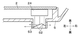
また、図3に示すように、第2のケース5には、発音手段24に対向する箇所に、反射面52が設けられる。反射面52は、発音手段24から車両用計器Aの裏側へ出力される音に対して、車両用計器Aの左側方向へ反射する左反射面52aと、右側方向へ反射する右反射面52bとが、発音手段24に対して傾斜した面によって形成されている。この反射面52によって反射された、音は、スリット53を抜けて、車両用計器Aの裏側へ伝わる。
As shown in FIG. 3, the
また、反射面52の左反射面52aと右反射面52bとは、異なる面積にて形成されている。この場合、発音手段24は、車両用計器Aの右側に設けられるため、左側に音が伝わり易いように右反射面52aよりも左反射面52bの面積が大きくなるようにしている。この面積比は、左右両方へ伝わる音量が近くなるように設定され、特に影響の大きい発音手段24の位置や音が伝わるための障害物位置などを考慮した形状にできる。
Further, the left reflecting surface 52a and the right reflecting surface 52b of the reflecting
特に、反射面52は、発音部材24に対向して反響する部材であり、指向性を調整する上で影響が大きく、左右への音量調整に有効である。なお、車両用計器Aが装着状態において、左側に発音手段24が設けられる場合には、右側に音が伝わり易いように左反射面よりも右反射面の面積を大きくすることで、左右の音量差を軽減できる。車両利用者は、車両用計器A全体から音が発せられるように感じられ、違和感なく発音を視聴できるため、商品性の高い車両用計器Aとなる。
In particular, the reflecting
また、反射面52は、裏側からみたときに略円状に形成され、頂点がこの略円状の中心でなく偏心した円錐形状の反射面を形成することによって、左右の反射面積が異なる反射形状を設けることもでき、車両用計器Aにおける発音手段24の位置などに応じて頂点位置を設定できる。この場合、車両用計器Aの車両への組み付け状態において、全周に渡って効率よく音を出力できるだけでなく、上下方向の音量調整も可能となる。
Further, the
斯かる車両用計器Aは、発音手段24と、車両情報に応じて警報状態の際に発音手段24の作動を制御する制御手段と、発音手段24や前記制御手段を収納するケース4,5と、を備えた車両用計器Aであって、この車両用計器Aが車両に組み付け状態におけるケース4,5内の左右いずれかに、発音手段24を設け、ケース5には、発音手段24に対向し、この発音手段24からの音をケース5の左右の両側へ反射可能な反射面52を形成し、この反射面52は、左右異なる面積で形成される。
Such a vehicle meter A includes a
従って、反射面52による反響によって、音の指向性を改善し、車両用計器A全体から発音しているように出力ができるため、車両利用者にとって聞き取りやすい音を発することができる車両用計器となる。
Therefore, the directivity of the sound is improved by the reverberation of the reflecting
また、車両情報を表示する表示器1を備え、発音手段24及び反射面52は、表示器1の背面側(裏側)に設けられるため、車両利用者から遠い車両用計器Aの裏側の空間にて左右の音量調整を行うことができる。
Moreover, since the
なお、本発明の車両用計器を上述した実施の形態の構成にて例に挙げて説明したが、本発明はこれに限定されるものではなく、他の構成においても、本発明の要旨を逸脱しない範囲において種々の改良、並びに表示の変更が可能なことは勿論である。スリット53は、図2に示すように、車両用計器Aの全周に同じ形状のものが等間隔にて形成されているが、例えば、車両用計器Aの左右方向のみに設けることで、上下方向に漏れる音を低減できる。特に、上下よりも左右が長い計器にあっては、左右の音の偏りを大きく軽減できる。
Although the vehicular instrument of the present invention has been described as an example in the configuration of the above-described embodiment, the present invention is not limited to this, and other configurations depart from the gist of the present invention. It goes without saying that various improvements and display changes can be made without departing from the scope. As shown in FIG. 2, the
また、反射面52の面積を左右で異ならせるだけでなく、スリットの大きさ(音を通す開口の大きさ)を左右側で異ならせることによって、出力される音量をより大きく調整できる。
Further, not only the area of the reflecting
また、上述の実施の形態では、表示器1として、液晶表示素子やバックライトを用いるものを示したが、例えば、制御手段による制御によって、車速などの計測値に基づいて回動する指針と、この指針の指示対象となる目盛りや数値表示などの指標部とによって対比判読する、指針式表示部を用いることもできる。この場合、該指針に発音手段24の振動が伝わりにくいように、発音手段24は、指針軸との距離をおいて回路基板2の端側に設けられる場合が多く、上述した発明が有効である。
In the above-described embodiment, the
本発明は、移動体に搭載して各種情報を表示する車両用計器に関して、例えば、自動車やオートバイ、あるいは農業機械や建設機械を備えた移動体に搭載される計器として適用できる。 INDUSTRIAL APPLICABILITY The present invention can be applied to a vehicle instrument that is mounted on a mobile body and displays various types of information, for example, as an instrument mounted on a mobile body equipped with an automobile, a motorcycle, an agricultural machine, or a construction machine.
1 表示器
2 回路基板
21 制御手段
24 発音手段
3 保持部材
4 第1のケース(ケース)
5 第2のケース(ケース)
52 反射面
53 スリット
DESCRIPTION OF
5 Second case (case)
52 Reflecting
Claims (2)
車両情報に応じて警報状態の際に前記発音手段の作動を制御する制御手段と、
前記発音手段や前記制御手段を収納するケースと、を備えた車両用計器であって、
この車両用計器が車両に組み付け状態における前記ケース内の左右いずれかに、前記発音手段を設け、
前記ケースには、前記発音手段に対向し、この発音手段からの音を前記ケースの左右の両側へ反射可能な反射面を形成し、この反射面は、左右異なる面積で形成されることを特徴とする車両用計器。 Pronunciation means;
Control means for controlling the operation of the sounding means in an alarm state according to vehicle information;
A vehicular instrument comprising a case housing the sounding means and the control means,
The sound generation means is provided on either the left or right side of the case when the vehicle instrument is assembled to the vehicle,
The case is formed with a reflecting surface facing the sounding means and capable of reflecting sound from the sounding means to both the left and right sides of the case, and the reflecting surfaces are formed with different areas on the left and right. Vehicle instrument.
前記発音手段及び前記反射面は、前記表示器の背面側に設けられることを特徴とする請求項1に記載の車両用計器。 A display for displaying the vehicle information;
The vehicle instrument according to claim 1, wherein the sound generation unit and the reflection surface are provided on a back side of the display.
Priority Applications (2)
| Application Number | Priority Date | Filing Date | Title |
|---|---|---|---|
| JP2013079211A JP2014201214A (en) | 2013-04-05 | 2013-04-05 | Instrument for vehicle |
| PCT/JP2014/059806 WO2014163129A1 (en) | 2013-04-05 | 2014-04-03 | Vehicular gauge |
Applications Claiming Priority (1)
| Application Number | Priority Date | Filing Date | Title |
|---|---|---|---|
| JP2013079211A JP2014201214A (en) | 2013-04-05 | 2013-04-05 | Instrument for vehicle |
Publications (1)
| Publication Number | Publication Date |
|---|---|
| JP2014201214A true JP2014201214A (en) | 2014-10-27 |
Family
ID=51658420
Family Applications (1)
| Application Number | Title | Priority Date | Filing Date |
|---|---|---|---|
| JP2013079211A Pending JP2014201214A (en) | 2013-04-05 | 2013-04-05 | Instrument for vehicle |
Country Status (2)
| Country | Link |
|---|---|
| JP (1) | JP2014201214A (en) |
| WO (1) | WO2014163129A1 (en) |
Family Cites Families (8)
| Publication number | Priority date | Publication date | Assignee | Title |
|---|---|---|---|---|
| JPH02113494U (en) * | 1989-01-17 | 1990-09-11 | ||
| JPH02237295A (en) * | 1989-03-10 | 1990-09-19 | Canon Inc | Audio output device |
| JPH02237345A (en) * | 1989-03-10 | 1990-09-19 | Matsushita Electric Ind Co Ltd | Telephone set stand |
| JP2771003B2 (en) * | 1990-01-23 | 1998-07-02 | キヤノン株式会社 | Audio mirror speaker |
| JP2008005346A (en) * | 2006-06-23 | 2008-01-10 | Yamaha Corp | Sound reflecting device |
| JP5150337B2 (en) * | 2007-12-04 | 2013-02-20 | 本田技研工業株式会社 | Vehicle anti-theft device |
| JP2009284464A (en) * | 2008-04-22 | 2009-12-03 | Nippon Seiki Co Ltd | Information provision device for vehicle |
| JP2010158968A (en) * | 2009-01-07 | 2010-07-22 | Denso Corp | Vehicular display device |
-
2013
- 2013-04-05 JP JP2013079211A patent/JP2014201214A/en active Pending
-
2014
- 2014-04-03 WO PCT/JP2014/059806 patent/WO2014163129A1/en active Application Filing
Also Published As
| Publication number | Publication date |
|---|---|
| WO2014163129A1 (en) | 2014-10-09 |
Similar Documents
| Publication | Publication Date | Title |
|---|---|---|
| JP2007003630A (en) | Display device | |
| JP2015098308A (en) | Vehicular instrument | |
| JP2008179237A (en) | Vehicular information provision device | |
| WO2014163129A1 (en) | Vehicular gauge | |
| JP6086221B2 (en) | Instrument ventilation structure | |
| JP2006173817A (en) | On-vehicle information providing apparatus | |
| JP4491723B2 (en) | Vehicle meter | |
| JP2015232497A (en) | Pointer instrument for vehicle | |
| JP5003061B2 (en) | Vehicle information providing device | |
| JP7156285B2 (en) | instrument | |
| JP2006232040A (en) | Vehicular information providing device | |
| JP2012127850A (en) | Display device | |
| JP2013120159A (en) | Vehicular display device | |
| JP2007248969A (en) | Sound producing device | |
| JP5131644B2 (en) | Display device | |
| JP7180672B2 (en) | vehicle instrument | |
| JP2018131129A (en) | Instrument device | |
| JP6056244B2 (en) | Pointer-type instrument device | |
| JP2013228341A (en) | Display device | |
| JP4826892B2 (en) | Vehicle meter | |
| JP2009284464A (en) | Information provision device for vehicle | |
| JP5083508B2 (en) | Vehicle information providing device | |
| JP2023047381A (en) | Instrument device | |
| JP5326967B2 (en) | Instrument device | |
| JP2014206435A (en) | Vehicle instrument |