JP2014200768A - Seawater type exhaust gas desulfurizer - Google Patents
Seawater type exhaust gas desulfurizer Download PDFInfo
- Publication number
- JP2014200768A JP2014200768A JP2013080923A JP2013080923A JP2014200768A JP 2014200768 A JP2014200768 A JP 2014200768A JP 2013080923 A JP2013080923 A JP 2013080923A JP 2013080923 A JP2013080923 A JP 2013080923A JP 2014200768 A JP2014200768 A JP 2014200768A
- Authority
- JP
- Japan
- Prior art keywords
- exhaust gas
- seawater
- region
- liquid
- spray nozzle
- Prior art date
- Legal status (The legal status is an assumption and is not a legal conclusion. Google has not performed a legal analysis and makes no representation as to the accuracy of the status listed.)
- Pending
Links
Images

Landscapes
- Treating Waste Gases (AREA)
- Gas Separation By Absorption (AREA)
Abstract
Description
本発明は、火力発電所や工場等に設置されるボイラ等の燃焼装置から発生する排ガス中の有害成分の硫黄酸化物、煤塵、重金属などを除去する排煙処理装置に係わり、特に、脱硫吸収液として海水を利用する海水式排煙脱硫装置に関する。 The present invention relates to a flue gas treatment apparatus for removing harmful components such as sulfur oxides, dust, and heavy metals in exhaust gas generated from a combustion apparatus such as a boiler installed in a thermal power plant or factory, in particular, desulfurization absorption. The present invention relates to a seawater type flue gas desulfurization apparatus that uses seawater as a liquid.
大気汚染防止のため、工場や製鉄所、化学プラント及び火力発電設備等の排ガス中の硫黄酸化物(SOx)の除去装置として排煙脱硫装置が設置されている。脱硫方式としては湿式石灰石−石膏法が世界的に主流であるが、特に開発途上国の海沿いの地域では、吸収液兼吸収剤に海水を使用する海水脱硫装置が設置されることも多い。 In order to prevent air pollution, a flue gas desulfurization device is installed as a device for removing sulfur oxide (SOx) in exhaust gas from factories, steelworks, chemical plants, thermal power generation facilities, and the like. As the desulfurization method, the wet limestone-gypsum method is the world's mainstream, but seawater desulfurization equipment that uses seawater as an absorbent and absorbent is often installed particularly in areas along the sea in developing countries.
一例として、特開2008−207149号公報(特許文献1)記載の火力発電プラントに設置された海水脱硫装置の構成を図4に示す。ボイラ1からの排ガスはエアヒータ(図示せず)により熱交換し、電気集塵機3で除塵が行われ、ファン4により昇圧される。その後昇圧された排ガスはガス-ガスヒータ(図示せず)で熱回収され、吸収塔6において海水噴霧ポンプ7により供給され、スプレされた清浄な海水ライン8中の海水と直接接触することにより、排ガス中の煤塵や塩化水素(HCl)、フッ化水素(HF)等の酸性ガスとともにSOxが吸収除去される。排ガスに同伴されるミストは吸収塔6の出口に設置されたミストエリミネータ(図示せず)により除去され、浄化された排ガスはガス-ガスヒータ(図示せず)により再加熱されて煙突10より排出される。
As an example, FIG. 4 shows a configuration of a seawater desulfurization apparatus installed in a thermal power plant described in Japanese Patent Application Laid-Open No. 2008-207149 (Patent Document 1). Exhaust gas from the
一方、煤塵やSOx等を吸収し、pHが低下した排海水ライン11中の排海水は全量がエアレーション設備(排水酸化槽)12に送られ、空気ブロワ14から供給される空気でエアレーションをし、pH及び溶存酸素濃度の回復、温度低下と各成分の希釈が行われ、海洋1へ戻される。また、吸収塔6でスプレされる清浄な海水は海水ライン8から新たに海洋1から汲上げられる。吸収塔6では通常このようなサイクルによりワンスルーで海水を供給する。
On the other hand, the entire amount of the wastewater in the
近年、世界の様々な地域で環境規制の開始や強化が行われており、工場や化学プラント、火力発電設備等で発生する排ガス浄化のために排煙脱硫装置が設置されることが多いが、そのような動きの中で設備投資を抑えるために、海に近い地域では設備費と運転費が比較的安価といわれている海水式を採用するケースが増加している。しかし通常の海水式による排煙脱硫では、吸収塔6で捕捉された煤塵や重金属類について、特別な処理が行われないまま海洋1へと戻されているため、周囲の海洋1が汚染され、二次公害が発生する可能性が懸念される。そのような二次公害の発生を防ぐためには、排水処理設備の設置といった対策が考えられるが、脱硫吸収液兼吸収剤として海水を大量に使用するため、排水処理設備自体と排水処理に係るコストが大きくなり、海水脱硫のコストメリットが失われる。
In recent years, environmental regulations have been started and strengthened in various regions of the world, and flue gas desulfurization equipment is often installed to purify exhaust gas generated in factories, chemical plants, thermal power generation facilities, etc. In order to curb capital investment in such a movement, there are increasing cases of adopting the seawater type, which is said to have relatively low facility and operating costs in areas close to the sea. However, in normal seawater type flue gas desulfurization, dust and heavy metals captured in the absorption tower 6 are returned to the
本発明の課題は、設備費及び運転費の増加を抑えてコストメリットを維持したまま、二次公害発生の可能性を低減し、より環境に配慮した海水式排煙脱硫装置を提供することにある。 An object of the present invention is to provide a seawater type flue gas desulfurization apparatus that is more environmentally friendly and reduces the possibility of secondary pollution while maintaining cost merit while suppressing increases in equipment costs and operating costs. is there.
本発明の上記課題は次の解決手段で解決される。
請求項1記載の発明は、ボイラを含む燃焼装置から排出される排ガスを入口ダクトからほぼ水平方向に導入し、出口ダクトからほぼ水平方向に排出する排ガス流路を有し、その排ガス流路を入口ダクト側と出口ダクト側の二室に分割するための天井側に開口部を有した仕切板を設けることで、入口ダクトから導入される排ガスが上向きに流れる上昇流領域と、天井側の開口部で反転した後に出口ダクトに向けて下向きに排ガスが流れる下降流領域を形成し、それぞれの領域に設置したスプレノズルから噴射される海水を用いた吸収液と排ガスを接触させて、それぞれの領域の下部に設けられた液溜めに吸収液を回収し、排ガス中の硫黄酸化物を処理する吸収塔を備えた海水式排煙脱硫装置において、排ガスと吸収液との接触が二段階で行われ、上昇流領域では排ガスと、液溜めから循環供給される吸収液とをスプレノズルからの噴霧により接触させ、液溜めから抜き出された液を排水処理設備で処理した後に排出し、下降流領域では排ガスと、海水源から採取された海水を吸収液としてスプレノズルからの噴霧により接触させて、液溜めの海水は循環使用を行わず、エアレーションした後に海洋に排水することを特徴とした海水式排煙脱硫装置である。
The above-mentioned problem of the present invention is solved by the following means.
The invention described in
請求項2記載の発明は、前記上昇流領域のガス流れ方向が上昇流であり、かつ前記吸収液が前記スプレノズルより向流接触となるように下向きに噴霧され、前記上昇流領域に設けられた最上段に設置するスプレノズルを他のスプレノズルより大きな液滴径の吸収液を噴霧するスプレノズルとし、液滴径の大きな吸収液により後段側への同伴ミストを低減させると同時に上昇流領域と下降流領域との吸収液の混合を抑制することを特徴とした請求項1に記載の海水式排煙脱硫装置である。
According to a second aspect of the present invention, the gas flow direction of the upflow region is an upflow, and the absorbing liquid is sprayed downward so as to be in a countercurrent contact from the spray nozzle, and is provided in the upflow region. The spray nozzle installed in the uppermost stage is a spray nozzle that sprays absorption liquid with a larger droplet diameter than other spray nozzles, and the entrained mist to the rear stage side is reduced by the absorption liquid with a larger droplet diameter, and at the same time, the upward flow area and the downward flow area The seawater-type flue gas desulfurization apparatus according to
請求項3記載の発明は、下降流領域の吸収塔ガス出口後流部にミストエリミネータを設置し、該ミストエリミネータのエレメント洗浄水を塩分を含まない水とし、該ミストエリミネータから排出された該洗浄水を前記上昇流領域の液溜めへの補給水として供給することを特徴とした請求項1又は2記載の海水式排煙脱硫装置である。
In the invention according to
請求項4記載の発明は、吸収塔内部の排ガスが、前記上昇流領域から前記下降流領域へ向かってターンする領域に排ガス整流板を設け、該排ガス整流板の端部に堰を設け、該排ガス整流板に衝突して前記堰に捕集された吸収液の液滴が前記上昇流領域に戻るように該排ガス整流板を配置することを特徴とした請求項1又は2記載の海水式排煙脱硫装置である。
The invention according to claim 4 provides an exhaust gas rectifying plate in a region where the exhaust gas inside the absorption tower turns from the upward flow region toward the downward flow region, and provides a weir at an end of the exhaust gas rectifying plate, The seawater-type exhaust gas according to
請求項5記載の発明は、前記排ガス整流板は排ガス流に対向する平面を円弧状に形成し、前記円弧状平面が鉛直方向に対して排ガス流の上流側に向けて傾斜させて設けられていることを特徴とした請求項4記載の海水式排煙脱硫装置である。 According to a fifth aspect of the present invention, the exhaust gas rectifying plate is formed such that a plane facing the exhaust gas flow is formed in an arc shape, and the arc-shaped plane is inclined toward the upstream side of the exhaust gas flow with respect to the vertical direction. The seawater type flue gas desulfurization apparatus according to claim 4, wherein
請求項6記載の発明は、前記排ガス整流板を複数設けたことを特徴とした請求項4又は5記載の海水式排煙脱硫装置である。 A sixth aspect of the present invention is the seawater type flue gas desulfurization apparatus according to the fourth or fifth aspect, wherein a plurality of the exhaust gas rectifying plates are provided.
請求項1記載の発明によれば、これまで海水式排煙脱硫装置において海洋へそのまま排出されていた煤塵や重金属類を、コスト増加を抑えつつ分離・除去して回収することができ、従来と比較してより環境に配慮した海水式排煙脱硫装置の設置が可能となる。 According to the first aspect of the present invention, dust and heavy metals that have been discharged to the ocean as they are in the seawater-type flue gas desulfurization apparatus can be separated and removed while suppressing an increase in cost. In comparison, it is possible to install a seawater type flue gas desulfurization apparatus that is more environmentally friendly.
請求項2記載の発明によれば、上記請求項1記載の発明の効果に加えて、排ガスの上昇流領域の最上段のスプレを他のスプレより液滴径の粗いものとすることにより、前段の排ガスの上昇流領域と後段の排ガスの下降流領域との境界領域にミストエリミネータを設置することなく後段の排ガスの下降流領域へのミスト飛散を低減することができ、設備費の増加を抑えるとともに、前段側の排ガスの上昇流領域と後段側の下降流領域での噴霧吸収液の混合を避け、海洋への汚染物質の流出を更に低減することが可能となる。また、上記のように脱硫装置における全排水の一部、すなわち前段側の排ガス上昇流領域で回収した煤塵や重金属類を含む吸収液のみを排水処理設備で処理するため、排水処理に係る設備費及び運転費の増加を抑えることが可能である。
According to the invention described in claim 2, in addition to the effect of the invention described in
請求項3記載の発明によれば、上記請求項1又は2記載の発明の効果に加えて、吸収塔の排ガス出口部に設置したミストエリミネータのエレメント洗浄水を海水でなく真水とすることにより、吸収塔より後流側の煙道や機器への海水の飛散を防ぎ、これら煙道や機器の腐食及び閉塞の低減、防止が可能となるとともに、使用後の洗浄水を吸収塔の前段側排ガス上昇流領域への補給水として使用することで、前段側の排ガス上昇流領域における補給水量の低減を図ることが可能となる。
According to the invention described in
請求項4記載の発明によれば、上記請求項1又は2記載の発明の効果に加えて、吸収塔の排ガスが前段側から後段側へ向かってターンする箇所に、端部に堰を有する排ガス整流板を、整流板との慣性衝突によって捕集されたミスト・液滴が堰を伝って前段側へ戻るように配置することにより、前段側から後段側への吸収液の流入及び混合を低減することが可能となる。
According to the invention described in claim 4, in addition to the effect of the invention described in
請求項5記載の発明によれば、上記請求項4記載の発明の効果に加えて、排ガス整流板の形状を円弧状として、鉛直方向に対して排ガスの上流側に向けて傾斜させて配置することにより、排ガス整流板で捕集されたミストが排ガス整流板の両端から排ガスの上昇流領域側にスムーズに回収される。 According to the invention described in claim 5, in addition to the effect of the invention described in claim 4, the shape of the exhaust gas rectifying plate is formed in an arc shape, and is inclined to the upstream side of the exhaust gas with respect to the vertical direction. Thus, the mist collected by the exhaust gas rectifying plate is smoothly recovered from both ends of the exhaust gas rectifying plate to the exhaust gas upward flow region side.
請求項6記載の発明によれば、上記請求項4又は5記載の発明の効果に加えて、排ガス整流板を複数設けることでミストの捕集効果を高めることができる。 According to the invention described in claim 6, in addition to the effect of the invention described in claim 4 or 5, the mist collecting effect can be enhanced by providing a plurality of exhaust gas rectifying plates.
以下に、本発明の実施例について図面を用いて説明する。 Embodiments of the present invention will be described below with reference to the drawings.
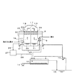
本発明の実施例1として吸収塔が一塔の場合の海水式脱硫装置の構成を図1に示す。ボイラ等からの排ガス16は図示されていないエアヒータ、電気集塵機等を経て煙道より吸収塔に導入される。吸収塔は仕切板17により液溜部を含めて上昇流領域18と下降流領域19の二区画に分けられている。まず吸収塔入口から上昇流領域18に導入された排ガス16は上向きに方向を変え、循環タンク部20から循環ポンプ21によって上昇流領域18で下向きに循環噴霧される吸収液と向流スプレ部22で向流接触し、除塵と重金属類の除去と酸性ガスの除去が行われる。
FIG. 1 shows the configuration of a seawater-type desulfurization apparatus when the number of absorption towers is one as Example 1 of the present invention.
向流スプレ部22の最上段のスプレノズルは、他のスプレノズルよりも噴霧される液滴径の大きい粗液滴スプレ23であり、境界にミストエリミネータを設置することなく、下降流領域19へのミスト飛散が低減され、上昇流領域18の補給水量が低減されるとともに、上昇流領域18で除去した煤塵や重金属類の海水への流出を更に低減することが可能となる。また、このとき補給水として海水若しくは塩分を含まない水が供給され、同時に吸収液の一部を抜き出す。その後、排ガス16は下降流領域19において、海水噴霧ポンプ7によりワンスルーで供給され、下向きに噴霧される清浄な海水と並流スプレ部24にて並流接触し、更に酸性ガスの除去が行われ、吸収塔出口後流のミストエリミネータ9にてミストを除去される。このとき、ミストエリミネータ9のエレメント洗浄には塩分を含まない水を使用し、後流の煙道や機器の腐食・閉塞を防ぐ。使用後、前記ミストエリミネータ9を洗浄後の洗浄水は洗浄水ライン25を経由し上昇流領域18の補給水として供給される。清浄な排ガスは、ガス-ガスヒータが設置されている場合は再加熱され、煙突より排出される。
The uppermost spray nozzle of the
一方で排水については、上昇流領域18では吸収性能を維持するため、吸収液の一部が濃縮排水として排水ライン26を経由して循環ライン30より抜出されて、排水処理設備27に送られ浄化処理される。浄化された処理済み排水は、排水ライン28からワンスルーで、ダウンフロー側の排海水11と同様に、エアレーション設備12において処理を行われた後、海洋15に戻される。
On the other hand, with respect to the drainage, in order to maintain the absorption performance in the
本発明のその他の実施例を図2に示す。本実施例においては、図1に示す海水式排煙脱硫装置に比べて、吸収塔内の排ガス上昇流領域18の補給水及び吸収塔排ガス出口のミストエリミネータ9のエレメント洗浄水として海水のみを使用すること、使用後の洗浄水を洗浄水ライン25からそのまま又は排ガス下降流領域19の排海水11と混合して処理すること、及び塔内の排ガス上昇流領域18から下降流領域19へのガスターン部に堰付き排ガス整流板29を設置したことを特徴とする。
Another embodiment of the present invention is shown in FIG. In this embodiment, as compared with the seawater type flue gas desulfurization apparatus shown in FIG. 1, only seawater is used as the makeup water for the exhaust gas upward flow
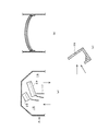
堰付き排ガス整流板29の構造・配置の一例を図3に示す。図3(a)は図2の吸収塔排ガス上昇流領域18から下降流領域19へのガスターン部の拡大図、図3(b)は排ガス上昇流領域18側(矢印A側)から見た吸収塔排ガス上昇流領域18から下降流領域19へのガスターン部の拡大図、図3(c)は堰付き排ガス整流板29の断面図である。
An example of the structure / arrangement of the weir exhaust
図3に示す堰付き排ガス整流板29は断面がコの字状で、排ガスの上流側が短く、排ガスの下流側が長くなっており、コの字状の長い方が短い方に比較してその端部が上方に来るように、鉛直方向に対して排ガス流の上流側に向けて傾斜させて配置される。また、堰付き排ガス整流板29の長手方向は円弧状で、前述のように傾斜させて配置することにより、長手方向の端部が最下端となり、捕集されたミストを排出されやすいようになっている。さらに、堰付き排ガス整流板29は1箇所設けることも、複数設けることも可能である。
3 has a U-shaped cross section, the upstream side of the exhaust gas is short, the downstream side of the exhaust gas is long, and the longer U-shaped side is shorter than the shorter side. It is arranged to be inclined toward the upstream side of the exhaust gas flow with respect to the vertical direction so that the portion comes upward. Moreover, the longitudinal direction of the exhaust
真水の使用量を極力低減したい場合は、このように代替として海水のみを使用し、かつ堰付きガス整流板29によりダウンフロー側19への吸収液の流入・混合を低減するとともに、前段側への補給水量の低減も図ることが可能である。
If you want to reduce the amount of fresh water as much as possible, use only seawater as an alternative, and reduce the inflow / mixing of the absorption liquid to the
9 ミストエリミネータ
11 排海水
12 エアレーション設備
16 排ガス
17 仕切板
18 上昇流領域
19 下降流領域
20 循環タンク部
21 循環ポンプ
22 向流スプレ部
23 粗液滴スプレ
24 並流スプレ部
25 洗浄水ライン
26 排水ライン
27 排水処理設備
28 排水ライン
29 堰付き排ガス整流板
30 循環ライン
9
Claims (6)
排ガスと吸収液との接触が二段階で行われ、上昇流領域では排ガスと、液溜めから循環供給される吸収液とをスプレノズルからの噴霧により接触させ、液溜めから抜き出された液を排水処理設備で処理した後に排出し、
下降流領域では排ガスと、海水源から採取された海水を吸収液としてスプレノズルからの噴霧により接触させて、液溜めの海水は循環使用を行わず、エアレーションした後に海洋に排水することを特徴とした海水式排煙脱硫装置。 It has an exhaust gas flow path that introduces exhaust gas discharged from a combustion device including a boiler in a substantially horizontal direction from the inlet duct and discharges it in a substantially horizontal direction from the outlet duct. The exhaust gas flow paths are arranged on the inlet duct side and the outlet duct side. By providing a partition plate with an opening on the ceiling side to divide into two chambers, the exhaust gas introduced from the inlet duct flows upward, and the outlet duct after being inverted at the ceiling side opening A downward flow area where the exhaust gas flows downward is formed, and the absorption liquid using seawater sprayed from the spray nozzle installed in each area is brought into contact with the exhaust gas to form a reservoir provided at the lower part of each area. In the seawater-type flue gas desulfurization device equipped with an absorption tower that collects the absorbing liquid and treats sulfur oxides in the exhaust gas,
The exhaust gas and the absorbing liquid are contacted in two stages. In the upward flow region, the exhaust gas and the absorbing liquid circulated and supplied from the liquid reservoir are contacted by spraying from the spray nozzle, and the liquid extracted from the liquid reservoir is drained. Discharge after processing at the processing facility,
In the downflow region, exhaust gas and seawater collected from the seawater source are brought into contact with each other by spraying from the spray nozzle as absorption liquid, and the seawater in the reservoir is not circulated but drained to the ocean after aeration. Seawater type flue gas desulfurization equipment.
Priority Applications (1)
| Application Number | Priority Date | Filing Date | Title |
|---|---|---|---|
| JP2013080923A JP2014200768A (en) | 2013-04-09 | 2013-04-09 | Seawater type exhaust gas desulfurizer |
Applications Claiming Priority (1)
| Application Number | Priority Date | Filing Date | Title |
|---|---|---|---|
| JP2013080923A JP2014200768A (en) | 2013-04-09 | 2013-04-09 | Seawater type exhaust gas desulfurizer |
Publications (1)
| Publication Number | Publication Date |
|---|---|
| JP2014200768A true JP2014200768A (en) | 2014-10-27 |
Family
ID=52351717
Family Applications (1)
| Application Number | Title | Priority Date | Filing Date |
|---|---|---|---|
| JP2013080923A Pending JP2014200768A (en) | 2013-04-09 | 2013-04-09 | Seawater type exhaust gas desulfurizer |
Country Status (1)
| Country | Link |
|---|---|
| JP (1) | JP2014200768A (en) |
Cited By (3)
| Publication number | Priority date | Publication date | Assignee | Title |
|---|---|---|---|---|
| CN105417675A (en) * | 2015-12-09 | 2016-03-23 | 大唐环境产业集团股份有限公司 | Device and method for restoring desulphurized sea water based on pure oxygen aeration |
| CN106145230A (en) * | 2016-08-30 | 2016-11-23 | 成都锐思环保技术股份有限公司 | A kind of fume afterheat processes the system and method for desulfurization wastewater |
| KR20190073783A (en) * | 2017-12-19 | 2019-06-27 | 두산중공업 주식회사 | Wet desulfurization apparatus capable of improving desulfurization efficiency and wet desulfurization method using the same |
-
2013
- 2013-04-09 JP JP2013080923A patent/JP2014200768A/en active Pending
Cited By (6)
| Publication number | Priority date | Publication date | Assignee | Title |
|---|---|---|---|---|
| CN105417675A (en) * | 2015-12-09 | 2016-03-23 | 大唐环境产业集团股份有限公司 | Device and method for restoring desulphurized sea water based on pure oxygen aeration |
| CN106145230A (en) * | 2016-08-30 | 2016-11-23 | 成都锐思环保技术股份有限公司 | A kind of fume afterheat processes the system and method for desulfurization wastewater |
| KR20190073783A (en) * | 2017-12-19 | 2019-06-27 | 두산중공업 주식회사 | Wet desulfurization apparatus capable of improving desulfurization efficiency and wet desulfurization method using the same |
| US10561981B2 (en) | 2017-12-19 | 2020-02-18 | DOOSAN Heavy Industries Construction Co., LTD | Wet desulfurization apparatus capable of improving desulfurization efficiency and wet desulfurization method using the same |
| KR102110511B1 (en) * | 2017-12-19 | 2020-05-28 | 두산중공업 주식회사 | Wet desulfurization apparatus capable of improving desulfurization efficiency and wet desulfurization method using the same |
| US10870081B2 (en) | 2017-12-19 | 2020-12-22 | DOOSAN Heavy Industries Construction Co., LTD | Wet desulfurization apparatus capable of improving desulfurization efficiency and wet desulfurization method using the same |
Similar Documents
| Publication | Publication Date | Title |
|---|---|---|
| WO2014156985A1 (en) | Seawater flue-gas desulfurization device and method for operating same | |
| CN104524948B (en) | A kind of ultrasonic wave desulphurizing and dust-removing integral minimum discharge method | |
| EP2168655B1 (en) | Exhaust gas cleaning apparatus | |
| JP4854270B2 (en) | Gas purification apparatus and method | |
| JP2015174025A (en) | Seawater flue gas desulfurization apparatus and application method of the same | |
| JP2014217809A (en) | Flue gas desulfurization apparatus | |
| JP5705443B2 (en) | Finishing flue gas desulfurization apparatus and exhaust gas treatment system using the same | |
| KR100613264B1 (en) | Wet type scrubber for exhaust gas | |
| JP2009240908A (en) | Wet two step flue gas desulfurization apparatus and operation method of wet two step flue gas desulfurization apparatus | |
| JP2010115602A (en) | Two-step wet desulfurization method and apparatus | |
| CN203329558U (en) | Wet-type flue gas desulfurization tail gas repurifying device | |
| WO2014038354A1 (en) | Desulfurization device, and soot removal system | |
| JP6663481B2 (en) | In-line dual water scrubber and method for cleaning gas inside a ship | |
| CN104324593A (en) | Ship waste gas double-loop washing and desulfurization device combining seawater and fresh water | |
| JP2015150466A (en) | Wet flue-gas desulfurization apparatus | |
| KR20150070110A (en) | A flue gas purification device | |
| CN102008882A (en) | Fenton reagent for denitration of power plant smoke and denitration method by using the same | |
| KR100638517B1 (en) | Scrubber having diffraction plate | |
| JP2014200768A (en) | Seawater type exhaust gas desulfurizer | |
| JP4905926B2 (en) | Two-chamber wet flue gas desulfurization system | |
| CN205182493U (en) | A absorption tower device for SOx/NOx control | |
| KR20180079492A (en) | scrubber system having the cooling apparatus | |
| JP2012196611A (en) | Flue gas desulfurization apparatus and flue gas desulfurization method | |
| JP2008062205A (en) | Gas cleaning apparatus, flue gas desulfurization system, and waste gas treatment method | |
| KR101762903B1 (en) | Apparatus for reducing water and air pollutant |
Legal Events
| Date | Code | Title | Description |
|---|---|---|---|
| A711 | Notification of change in applicant |
Free format text: JAPANESE INTERMEDIATE CODE: A712 Effective date: 20141219 |