JP4905926B2 - Two-chamber wet flue gas desulfurization system - Google Patents
Two-chamber wet flue gas desulfurization system Download PDFInfo
- Publication number
- JP4905926B2 JP4905926B2 JP2006125378A JP2006125378A JP4905926B2 JP 4905926 B2 JP4905926 B2 JP 4905926B2 JP 2006125378 A JP2006125378 A JP 2006125378A JP 2006125378 A JP2006125378 A JP 2006125378A JP 4905926 B2 JP4905926 B2 JP 4905926B2
- Authority
- JP
- Japan
- Prior art keywords
- spray
- exhaust gas
- spray nozzle
- region
- guide plate
- Prior art date
- Legal status (The legal status is an assumption and is not a legal conclusion. Google has not performed a legal analysis and makes no representation as to the accuracy of the status listed.)
- Expired - Fee Related
Links
Images


Description
本発明は、ボイラなどの燃焼装置から排出される排ガス中の二酸化硫黄(SO2)を除去する湿式排煙脱硫装置に係わり、特に、吸収塔内部への仕切板の設置によって、排ガスが上向きに流れる上昇流領域と下向きに流れる下降流領域の二つの気液接触部に分けられた二室型の脱硫装置において、ガイドプレートのスケーリングを防止できる機能を備えた二室型湿式排煙脱硫装置に関するものである。 The present invention relates to a wet flue gas desulfurization apparatus that removes sulfur dioxide (SO 2 ) in exhaust gas discharged from a combustion apparatus such as a boiler, and in particular, the exhaust gas is directed upward by installing a partition plate inside the absorption tower. The present invention relates to a two-chamber wet flue gas desulfurization apparatus having a function capable of preventing scaling of a guide plate in a two-chamber desulfurization apparatus divided into two gas-liquid contact portions of a flowing upward flow area and a downward flowing area flowing downward. Is.
火力発電所等において、化石燃料の燃焼に伴って発生する排煙中の硫黄酸化物、中でも特にSO2は大気汚染・酸性雨等の環境問題における主原因の一つであり、近年地球的規模で排煙脱硫装置の普及が望まれている。
現在の脱硫システムは石灰石−石膏法による湿式法が主流を占めており、中でも最も実績が多く信頼性の高いスプレ方式が世界的にも多く採用されている。このスプレ式脱硫装置は脱硫性能が高く、基本技術はほぼ確立されている。
In thermal power plants, etc., sulfur oxides in flue gas generated by fossil fuel combustion, especially SO 2 is one of the main causes of environmental problems such as air pollution and acid rain. Therefore, the spread of flue gas desulfurization equipment is desired.
In the current desulfurization system, the wet method based on the limestone-gypsum method occupies the mainstream, and among them, the most reliable and reliable spray method is adopted worldwide. This spray-type desulfurization apparatus has high desulfurization performance, and the basic technology is almost established.
しかしながら、湿式排煙脱硫装置は高価であるため、未だ発展途上国などでの普及率は低い。したがって、世界的に脱硫装置の普及率を高めるためには、脱硫装置の設備費および運転費の大幅な低減が必要である。 However, since wet flue gas desulfurization equipment is expensive, the diffusion rate in developing countries is still low. Therefore, in order to increase the diffusion rate of desulfurization equipment worldwide, it is necessary to significantly reduce the equipment cost and operation cost of the desulfurization equipment.
従来技術のスプレ方式を採用し、低コスト化を図った二室型の湿式排煙脱硫装置の公知例(特開2001−79337号公報)を図7に示す。
図7に示す湿式排煙脱硫装置は、主に吸収塔本体1、入口ダクト2、出口ダクト3、仕切板4、吸収液循環ポンプ5、循環タンク7、攪拌機8、空気吹込み管9、ミストエリミネータ10、吸収液抜出し管11、上昇流領域12、下降流領域13、スプレ配管14〜15、スプレノズル16、17、ガイドプレート18等から構成される。
FIG. 7 shows a known example (Japanese Patent Laid-Open No. 2001-79337) of a two-chamber type wet flue gas desulfurization apparatus that employs a spray system of the prior art and achieves cost reduction.
The wet flue gas desulfurization apparatus shown in FIG. 7 is mainly composed of an absorption tower body 1, an
図7に示す吸収塔本体1内には、該吸収塔本体1の下部構造をなす循環タンク7の吸収液中に、その下端部を浸漬させた仕切板4を吸収塔本体1の鉛直方向上方に配置し、出口ダクト3を入口ダクト2とほぼ同じ高さに設けているため、入口ダクト2から導入されたボイラなどから排出される排ガスは、仕切板4に遮られて上昇流領域12となり上昇して塔頂部で反転した後、ガイドプレート18を通過し、下降流領域13を下降する。
In the absorption tower main body 1 shown in FIG. 7, a partition plate 4 having its lower end immersed in the absorption liquid of a
上昇流領域12にあり、ガス流れに対向する方向に吸収液を噴霧するスプレノズル16はガス流れに直交する断面内に複数個設置されており、更にガス流れ方向に複数段設置されている。また、下降流領域13にあり、ガス流れに沿った方向に吸収液を噴霧するスプレノズル17はガス流れに直交する断面内に複数個設置されており、更にガス流れ方向に複数段設置されている。また、攪拌機8及び空気吹込み管9は、吸収液が滞留する循環タンク7に設置され、ミストエリミネータ10は出口ダクト3内に設置される。
A plurality of
前記上昇流領域12および下降流領域13では、吸収液循環ポンプ5から送られる炭酸カルシウムを含んだ吸収液が、それぞれの領域に設けられたスプレノズル16,17から噴射され、吸収液と排ガスの気液接触が行われる。このとき吸収液は排ガス中のSO2を選択的に吸収し、亜硫酸カルシウムを生成する。亜硫酸カルシウムを生成した吸収液は一旦循環タンク7に溜まり、酸化用攪拌機8によって攪拌されながら、空気吹込み管9から供給される空気中の酸素により亜硫酸カルシウムが酸化され、硫酸カルシウム(石膏)を生成する。
In the
炭酸カルシウム及び石膏が共存する循環タンク7内の吸収液の一部は、吸収液循環ポンプ5によってスプレ配管14、15を介して再びスプレノズル16,17にそれぞれ送られ、一部は吸収液抜き出し管11より図示していない廃液処理・石膏回収系へと送られる。また、スプレノズル16,17からの噴射によって微粒化された吸収液の中で、液滴径の小さいものは排ガスに同伴されるが、出口ダクト3に設けられたミストエリミネータ10によって捕集される。
A part of the absorption liquid in the
図7に示す従来技術は、出口ダクト3が入口ダクト2とほぼ同じように低い位置の吸収塔本体1の側壁に設けられているため、図示していないミストエリミネータ10および出口ダクト3の支持鉄骨が比較的低く、簡易なもので良く、また、図示していない熱交換器(再加熱側)に接続するためのダクトの長さも短くて済む。
上記特許文献1記載の発明では、下降流領域13の上側に3枚の平板からなるガイドプレート18を並列設置し、下降流領域13入口の壁面側の流路を他の流路に比べて絞っている。
上記従来技術では、上昇流領域12及び下降流領域13の各最上段スプレ配管14、15、二室型吸収塔の排ガスが下向きに反転するガイドプレート18及び二室型吸収塔の天井部において排ガス中の亜硫酸カルシウムが付着することにより、スケーリングが発生する可能性があった。更に、長期間の運転に伴い、吸収塔内の機器に付着するスケーリング量が増大し、排ガス流れの圧力損失が増加するという可能性もあった。
そこで、本発明の課題は、吸収塔内に設置した各部材にスケーリングが付着することを防止して信頼性が高くかつ安定した運転が可能な湿式排煙脱硫装置を得ることにある。
In the invention described in Patent Document 1, a
In the above prior art, the
Therefore, an object of the present invention is to obtain a wet type flue gas desulfurization apparatus that prevents scaling from adhering to each member installed in an absorption tower and is capable of high reliability and stable operation.
上記本発明の課題は、次の各解決手段で解決される。
請求項1記載の発明は、(a)吸収液を貯留する循環タンクと、(b)該循環タンクの上側に燃焼装置から排出される排ガスをほぼ水平方向に導入する入口ダクトと排ガスをほぼ水平方向に排出させる出口ダクトを設け、前記入口ダクトと出口ダクトの間に排ガス流路を設け、その排ガス流路を入口ダクト側と出口ダクト側の二室に分割し、天井部側の上端部と吸収塔天井部との間に排ガス流路となる開口部を確保し、下端部を循環タンク内の吸収液中に浸漬した鉛直方向に平面を有する仕切板を設け、該仕切板で入口ダクトから導入される排ガスが上向きに流れる上昇流領域と前記天井側の開口部で反転した後に出口ダクトに向けて下向きに排ガスが流れる下降流領域を形成し、噴出する吸収液スラリが排ガスと上昇流領域では向流接触し、下降流領域では並流接触するように前記各領域に複数のスプレ配管と該配管毎に複数のスプレノズルを設けた二室式吸収塔とを備えた二室型湿式排煙脱硫装置において、前記天井側の開口部で反転した排ガスの流れを整流するためのガイドプレートを下降流領域の入口部に設け、下降流領域に設けたスプレ配管の中の少なくとも1個のスプレ配管は少なくとも1個の前記ガイドプレートと接合し、ガイドプレートと接合したスプレ配管に設けたスプレノズルから噴霧する吸収液が前記ガイドプレートに接触する位置に前記スプレノズルと前記ガイドプレートを配置した二室型湿式排煙脱硫装置である。
The above-described problems of the present invention are solved by the following respective solutions.
The invention described in claim 1 includes: (a) a circulation tank that stores the absorbing liquid; and (b) an inlet duct that introduces exhaust gas discharged from the combustion device in a substantially horizontal direction above the circulation tank and the exhaust gas substantially horizontally. An exhaust duct is provided to discharge in the direction, an exhaust gas flow path is provided between the inlet duct and the outlet duct, the exhaust gas flow path is divided into two chambers on the inlet duct side and the outlet duct side, An opening serving as an exhaust gas flow path is secured between the absorption tower ceiling and a partition plate having a vertically flat surface with a lower end immersed in the absorption liquid in the circulation tank is provided. An upward flow region where the exhaust gas to be introduced flows upward and a downward flow region where the exhaust gas flows downward toward the outlet duct after reversing at the opening on the ceiling side are formed, and the absorbing liquid slurry to be ejected is the exhaust gas and the upward flow region In counter current contact In the two-chamber wet flue gas desulfurization apparatus comprising a two-chamber type absorption tower provided with a plurality of spray pipes in each of the areas and a plurality of spray nozzles for each pipe so as to be in parallel flow contact in the downflow area, the ceiling A guide plate for rectifying the flow of the exhaust gas reversed at the opening on the side is provided at the inlet of the downflow region, and at least one of the spray pipes provided in the downflow region has at least one of the above-mentioned spray pipes A two-chamber wet-type flue gas desulfurization apparatus in which the spray nozzle and the guide plate are arranged at a position where the absorbing liquid sprayed from the spray nozzle provided in the spray pipe joined to the guide plate contacts the guide plate. is there.
請求項2記載の発明は、更に、天井部にスプレ配管と該スプレ配管に下向きに吸収液を噴霧するスプレノズルを設けた請求項1記載の二室型湿式排煙脱硫装置である。
請求項3記載の発明は、更に、天井部に下向きに吸収液を噴霧するスプレノズルと該下向きスプレノズルに対向する位置に衝突板を設けた請求項1記載の二室型湿式排煙脱硫装置である。
The invention according to
According to a third aspect of the invention, further, a two-chamber wet flue gas desulfurization apparatus according to claim 1 Symbol placement provided a collision plate in a position facing the spray nozzle and the lower facing spray nozzle for spraying the absorption liquid downwardly ceiling is there.
請求項4記載の発明は、更に、上昇流領域の最上段スプレ配管に上向きに吸収液を噴霧するスプレノズルと該上向きスプレノズルに対向する位置に衝突板を設けた請求項1又は請求項3に記載の二室型湿式排煙脱硫装置である。
Invention according to claim 4, further to claim 1 or
請求項1記載の発明によれば、二室型吸収塔のスプレノズル部、天井部及びガイドプレートのスケーリングを防止できるため、ガス偏流による脱硫性能低下を防止できる。また、スケーリングを起因とするガイドプレートを通過する排ガスの流速上昇も防止できるため、吸収塔の圧力損失が低くなり、吸収液噴霧用の動力などを低減することも可能となる。従って安定に運転を継続することが可能となる。また、ガイドプレートとノズル配管を接合したことによりガイドプレートの支持を兼ねることが出来るため、構造材の低減が可能となる。 According to invention of Claim 1, since the scaling of the spray nozzle part of a two-chamber type absorption tower, a ceiling part, and a guide plate can be prevented, the desulfurization performance fall by gas drift can be prevented. Moreover, since the increase in the flow velocity of the exhaust gas passing through the guide plate due to scaling can be prevented, the pressure loss of the absorption tower is reduced, and the power for spraying the absorbing liquid can be reduced. Therefore, it is possible to continue operation stably. In addition, since the guide plate and the nozzle pipe can be joined together to support the guide plate, the structure material can be reduced.
また、ガイドプレート近傍のスプレノズルから吸収液を噴霧することにより、ガスを湿潤状態にでき、かつ直接ガイドプレートを洗浄できることで、ガイドプレートへ付着した微少量のスケールを除去できるため、高効率のスケール除去が可能となる。
請求項2記載の発明によれば、請求項1に記載の発明の効果に加えて、天井部に設けたスプレノズルから吸収液を噴霧できるので、天井部のスケーリングを防止できるため、ガス偏流による脱硫性能低下を防止できる。
Moreover, by spraying the absorption liquid from the spray nozzle of the guide plate near the gas can in the wet state, and by directly guiding plate can be cleaned, since it removes a minute amount scale adhering to the guide plates, high-efficiency scale Removal is possible.
According to the second aspect of the invention, in addition to the effect of serial placement of the invention in claim 1, it is possible to spray the absorption liquid from the spray nozzle provided in a ceiling portion, it is possible to prevent the scaling of the ceiling portion, with a gas drift Degradation of desulfurization performance can be prevented.
請求項3記載の発明によれば、請求項1に記載の発明の効果に加えて、天井部に洗浄用のスプレノズルと該スプレノズルに対向する位置に設けた衝突板の跳ね返りにより天井部及びその近傍は常に湿潤状態となり、吸収塔壁面に亜硫酸カルシウムが付着した場合でも、酸化されることなく洗浄されることから、スケーリングを防止することができる。
According to the invention described in
請求項4記載の発明によれば、請求項1又は請求項3に記載の発明の効果に加えて、上昇流領域の最上段スプレ配管に上向きに吸収液を噴霧するスプレノズルを設け、該上向きスプレノズルに対向する位置に衝突板を設けたため、洗浄液を衝突板に衝突させて、吸収液を前記最上段スプレ配管の洗浄に直接利用できるので、この洗浄のみならずスプレノズルの詰まりもなく、常に正常な状態に保つことができる。
According to the invention described in claim 4 , in addition to the effect of the invention described in claim 1 or
また、天井部に洗浄用のスプレノズルと該スプレノズルに対向する位置に衝突板を設け、更に上昇流領域の最上段スプレ配管に上向きに吸収液を噴霧するスプレノズルと該上向きスプレノズルに対向する位置に衝突板を設けた場合は、天井部及びその近傍のスケーリングを防止するだけでなく、上昇流領域の最上段スプレ配管の洗浄によりスプレノズルへの詰まり防止と、ガイドプレートのスケーリングを防止できるので吸収塔圧力損失の上昇も防止できるため、吸収塔内への吸収液噴霧用の動力の運転に支障を起こすことなく安全に連続運転することができる。 In addition, a spray nozzle for cleaning and a collision plate are provided at the position facing the spray nozzle on the ceiling, and the spray nozzle that sprays the absorbing liquid upward on the uppermost spray pipe in the upflow region and the position facing the upward spray nozzle the case of providing the plate not only prevents scaling of the ceiling portion and the vicinity thereof, and clogging prevention of the spray nozzle by washing of the uppermost spray pipe upflow region, absorption column pressure can be prevented the scaling of the guide plates Since an increase in loss can also be prevented, continuous operation can be safely performed without hindering the operation of power for spraying the absorbing liquid into the absorption tower.
以下、本発明の実施例について図面を用いて説明する。
図1は本実施例の吸収塔の側面図であり、図2は図1の吸収塔のA−A線断面略図である。図1、図2に示す吸収塔は、図7の従来例の吸収塔のガイドプレート18に対して、これを支持するスプレノズル20を備えたノズル配管19を接合し、かつ天井部内壁側に沿って配置された洗浄液を流すスプレ配管22に多数取付けられたスプレノズル23を追加した構造からなる吸収塔である。なお図1、図2において図7に示す吸収塔の部材と同一部材には同一の符号を付してその説明は省略する。
Embodiments of the present invention will be described below with reference to the drawings.
FIG. 1 is a side view of the absorption tower of this embodiment, and FIG. 2 is a schematic cross-sectional view taken along line AA of the absorption tower of FIG. The absorption tower shown in FIGS. 1 and 2 is joined to the
入口ダクト2より吸収塔内に導入された排ガスは上昇流領域12を上昇した後、仕切板4の上端部と天井部との間の開口部を通過して下降流領域13の入口部にあるガイドプレート18の設置部で反転して下降流領域13に流入するが、本実施例の場合、スプレノズル20からの吸収液のスプレ効果によってガイドプレート18に付着した亜硫酸カルシウムが除去されるため、スケーリングを防止することができる。
The exhaust gas introduced into the absorption tower from the
また、天井部に設けたスプレノズル23からの吸収液のスプレにより天井部での排ガスの湿潤化が図れることから、天井部でのスケーリングの形成を防ぐことができる。更に、ガイドプレート18とスプレ配管19が接合されていることから、スプレ配管19がガイドプレート18を補強する役目も兼ねるため、当該ガイドプレート18を支持する鉄骨の設置数を低減することができる。
Moreover, since the exhaust gas is moistened at the ceiling by spraying the absorbing liquid from the
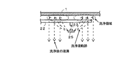
図3は、本実施例におけるスプレ配管19に設けられたスプレノズル20から噴霧後の吸収液膜とガイドプレート18の位置関係を示したものである。前記噴霧吸収液がガイドプレート18の湿潤化を図り、ガイドプレート18のスケーリングを防止するために、スプレノズル20はガイドプレート18の端部、もしくは下端部から上方にプレート高さの3分の2以上を濡らすことが可能な位置にあることが望ましい。
FIG. 3 shows the positional relationship between the absorbing liquid film after spraying from the
また図3に示すスプレノズル20は、吸収液を下方向に噴霧する配置であるが、これに限らず、吸収液を上方向に噴霧する配置、又は吸収液を上方と下方に向けて噴霧する配置など等いずれでも良い。
図4は本発明による他の実施例の吸収塔の側面図であり、図7の従来例の吸収塔に天井部に洗浄液を流すスプレ配管22と該配管に取り付けたスプレノズル23及び該ノズル23に対向する位置に衝突板25を設けることにより、天井部の洗浄機能を高め、更に上昇流領域12の最上段のスプレ配管14のスプレノズル16に上向きに吸収液を噴霧するスプレノズル16’と該ノズル16’に対向する位置に衝突板26を設けた構造からなる吸収塔である。なお、図4において図7に示す吸収塔の部材と同一部材には同一の符号を付してその説明は省略する。また、図示はしていないが、図1に図示するガイドプレート18にスプレノズル配管19を接合した構造を有する洗浄機構を設けている。
Moreover, although the
FIG. 4 is a side view of an absorption tower according to another embodiment of the present invention. In the conventional absorption tower of FIG. 7, a
入口ダクト2より導入された排ガスは、上昇流領域12を上昇した後、ガイドプレート18で反転して下降流領域13に流入するが、本実施例の場合にはスプレノズル16’から上向きに噴霧された吸収液のスプレ効果によって最上段の下向きのスプレ配管14のスケーリングを防止することができる。このことを図5(図4の最上段のスプレノズル16、16’の配置領域の拡大図)により説明すると、上昇流領域12の最上段のスプレ配管14にあるスプレノズル16’から上向に噴霧される吸収液に対向する位置に衝突板26を設けているので、該スプレノズル16’からの吸収液のスプレ効果によって最上段の下向きのスプレ配管14の上面に付着した亜硫酸カルシウムが除去される。
The exhaust gas introduced from the
また、図6に図4の吸収塔本体1の天井部の拡大図を示すように、吸収塔本体1の天井部に沿って配置されるスプレ配管22に取り付けたスプレノズル23から吸収液を噴霧すると衝突板25に当たり、その跳ね返り吸収液滴が天井部に飛び散るので天井部における排ガスの湿潤化が図れ、天井部でのスケーリングの形成を防ぐことができる。
Further, as shown in an enlarged view of the ceiling portion of the absorption tower main body 1 in FIG. 4, when the absorbing liquid is sprayed from the
こうして、吸収塔本体1内の天井部、更にスプレ部を通気する際の排ガスの偏流防止及び圧力損失低減を行うことができ、安定な運転が可能となる。この洗浄機構については、二室型湿式排煙脱硫装置のみならず、一室型湿式排煙脱硫装置にも同様構造にて適応することが可能である。 In this way, it is possible to prevent drift of exhaust gas and reduce pressure loss when ventilating the ceiling portion in the absorption tower body 1 and further the spray portion, and stable operation is possible. This cleaning mechanism is not only two-chamber type wet flue gas desulfurization apparatus, Ru can der be adapted in a similar structure to room type wet flue gas desulfurization system.
二室型湿式排煙脱硫装置を採用したプラントに対し、スケーリングが付着し易い部位のに洗浄液を噴霧する構成は産業上の利用可能性が高い。 In a plant that employs a two-chamber wet flue gas desulfurization apparatus, a configuration in which the cleaning liquid is sprayed on a portion where scaling is likely to adhere has high industrial applicability.
1 吸収塔本体 2 入口ダクト
3 出口ダクト 4 仕切板
5 吸収液循環ポンプ 7 循環タンク
8 攪拌機 9 空気吹込み管
10 ミストエリミネータ 11 吸収液抜出し管
12 上昇流領域 13 下降流領域
14、15、19、22 スプレ配管
16、16’、17、20、23 スプレノズル
18 ガイドプレート 24 傾斜壁面
25、26 衝突板
DESCRIPTION OF SYMBOLS 1
Claims (4)
前記天井側の開口部で反転した排ガスの流れを整流するためのガイドプレートを下降流領域の入口部に設け、下降流領域に設けたスプレ配管の中の少なくとも1個のスプレ配管は少なくとも1個の前記ガイドプレートと接合し、
ガイドプレートと接合したスプレ配管に設けたスプレノズルから噴霧する吸収液が前記ガイドプレートに接触する位置に前記スプレノズルと前記ガイドプレートを配置したことを特徴とする二室型湿式排煙脱硫装置。 (A) a circulation tank for storing the absorbent, (b) an inlet duct for introducing the exhaust gas discharged from the combustion device in a substantially horizontal direction and an outlet duct for discharging the exhaust gas in a substantially horizontal direction are provided above the circulation tank. An exhaust gas flow path is provided between the inlet duct and the outlet duct, the exhaust gas flow path is divided into two chambers on the inlet duct side and the outlet duct side, and between the upper end portion on the ceiling portion side and the absorption tower ceiling portion. An opening serving as an exhaust gas passage is secured, and a partition plate having a flat surface in which the lower end is immersed in the absorbing liquid in the circulation tank is provided, and the exhaust gas introduced from the inlet duct flows upward through the partition plate. A downflow region is formed in which the exhaust gas flows downward toward the outlet duct after reversing at the upflow region and the opening on the ceiling side, and the absorbing slurry that is ejected is in countercurrent contact with the exhaust gas and the upward flow region, and the downward flow Parallel flow welding in the region In the two-chamber type wet flue gas desulfurization apparatus and a dual chamber absorber tower having a plurality of spray nozzles into a plurality of spray pipes and each piping to the each region so as to,
A guide plate for rectifying the flow of the exhaust gas reversed at the opening on the ceiling side is provided at the inlet of the downflow region, and at least one spray pipe among the spray pipes provided in the downflow region is provided. Of the guide plate ,
A two-chamber wet flue gas desulfurization apparatus , wherein the spray nozzle and the guide plate are disposed at a position where an absorbing liquid sprayed from a spray nozzle provided in a spray pipe joined to the guide plate contacts the guide plate .
Priority Applications (1)
| Application Number | Priority Date | Filing Date | Title |
|---|---|---|---|
| JP2006125378A JP4905926B2 (en) | 2006-04-28 | 2006-04-28 | Two-chamber wet flue gas desulfurization system |
Applications Claiming Priority (1)
| Application Number | Priority Date | Filing Date | Title |
|---|---|---|---|
| JP2006125378A JP4905926B2 (en) | 2006-04-28 | 2006-04-28 | Two-chamber wet flue gas desulfurization system |
Publications (2)
| Publication Number | Publication Date |
|---|---|
| JP2007296447A JP2007296447A (en) | 2007-11-15 |
| JP4905926B2 true JP4905926B2 (en) | 2012-03-28 |
Family
ID=38766392
Family Applications (1)
| Application Number | Title | Priority Date | Filing Date |
|---|---|---|---|
| JP2006125378A Expired - Fee Related JP4905926B2 (en) | 2006-04-28 | 2006-04-28 | Two-chamber wet flue gas desulfurization system |
Country Status (1)
| Country | Link |
|---|---|
| JP (1) | JP4905926B2 (en) |
Families Citing this family (7)
| Publication number | Priority date | Publication date | Assignee | Title |
|---|---|---|---|---|
| JP5754892B2 (en) * | 2010-05-17 | 2015-07-29 | 三菱重工メカトロシステムズ株式会社 | Exhaust gas treatment apparatus and exhaust gas treatment method |
| CN103285715A (en) * | 2012-03-05 | 2013-09-11 | 无锡宏联电镀设备有限公司 | Horizontal type spraying waste gas purifying tower |
| JP6157912B2 (en) * | 2012-05-30 | 2017-07-05 | 株式会社東芝 | Carbon dioxide recovery system and operation method thereof |
| KR101794994B1 (en) | 2016-12-28 | 2017-11-24 | 주식회사 시원기업 | Dry waste gas cleaning apparatus for saving cooling water |
| CN107413178B (en) * | 2017-07-21 | 2023-04-28 | 华润电力(贺州)有限公司 | Double-tower mutually inverted desulfurization slurry dehydration system |
| KR102635282B1 (en) * | 2021-11-26 | 2024-02-08 | 주식회사 유성엔지니어링 | Wet-dry hybrid desulfurization device |
| CN115212697B (en) * | 2022-09-21 | 2022-12-06 | 河南省双碳研究院有限公司 | Amine absorption method CO 2 Alkaline washing tower for carbon capture |
Family Cites Families (5)
| Publication number | Priority date | Publication date | Assignee | Title |
|---|---|---|---|---|
| JPS60128721A (en) * | 1983-12-16 | 1985-07-09 | Toshiba Corp | Variable length encoding and decoding system |
| JPH09141048A (en) * | 1995-11-27 | 1997-06-03 | Babcock Hitachi Kk | Wet flue gas desulfurizing method and device therefor |
| JP2000354728A (en) * | 1999-06-16 | 2000-12-26 | Babcock Hitachi Kk | Gas-liquid contact device |
| JP2001017827A (en) * | 1999-07-08 | 2001-01-23 | Babcock Hitachi Kk | Double-chamber wet type flue gas desulfurization apparatus and method |
| JP3904771B2 (en) * | 1999-09-10 | 2007-04-11 | バブコック日立株式会社 | Two-chamber wet flue gas desulfurization system |
-
2006
- 2006-04-28 JP JP2006125378A patent/JP4905926B2/en not_active Expired - Fee Related
Also Published As
| Publication number | Publication date |
|---|---|
| JP2007296447A (en) | 2007-11-15 |
Similar Documents
| Publication | Publication Date | Title |
|---|---|---|
| JP4845568B2 (en) | Wet flue gas desulfurization equipment | |
| JP4905926B2 (en) | Two-chamber wet flue gas desulfurization system | |
| EP2073912B1 (en) | Method and apparatus for improved gas/fluid contact | |
| JP2010167330A (en) | Wet two-stage desulfurization equipment | |
| US6923852B2 (en) | Flue gas desulfurization system with a stepped tray | |
| JP5725725B2 (en) | Wet flue gas desulfurization equipment | |
| JP5967306B2 (en) | Desulfurization equipment | |
| KR20150070110A (en) | A flue gas purification device | |
| JP3776793B2 (en) | Wet flue gas desulfurization equipment | |
| JP2001327831A (en) | Wet type exhaust gas desulfurizer | |
| JP2002136835A (en) | Two-chamber type wet flue gas desulfurization apparatus | |
| JP2002253925A (en) | Wet type stack gas desulfurization apparatus | |
| JP2002248318A (en) | Wet flue gas desulfurizing apparatus | |
| JP3904771B2 (en) | Two-chamber wet flue gas desulfurization system | |
| JP2006320828A (en) | Wet-type flue gas desulfurization apparatus | |
| JP2004082037A (en) | Double chamber type wet type flue gas desulfurization equipment | |
| JP3805783B2 (en) | Two-chamber wet flue gas desulfurization apparatus and method | |
| JPH07155536A (en) | Wet type flue gas desulfurization apparatus | |
| JP4014073B2 (en) | Two-chamber wet flue gas desulfurization system | |
| JP3907873B2 (en) | Two-chamber wet flue gas desulfurization system | |
| JP3883745B2 (en) | Two-chamber wet flue gas desulfurization apparatus and method | |
| JP2001017827A (en) | Double-chamber wet type flue gas desulfurization apparatus and method | |
| JPH10192646A (en) | Horizontal flow and wet type flue gas desulfurization device with mist removing function | |
| EP3960276A1 (en) | Exhaust gas inlet structure of absorption column | |
| JP2002273160A (en) | Two-chamber type stack gas desulfurization facility |
Legal Events
| Date | Code | Title | Description |
|---|---|---|---|
| A621 | Written request for application examination |
Free format text: JAPANESE INTERMEDIATE CODE: A621 Effective date: 20081209 |
|
| A977 | Report on retrieval |
Free format text: JAPANESE INTERMEDIATE CODE: A971007 Effective date: 20100806 |
|
| A131 | Notification of reasons for refusal |
Free format text: JAPANESE INTERMEDIATE CODE: A131 Effective date: 20111018 |
|
| A521 | Request for written amendment filed |
Free format text: JAPANESE INTERMEDIATE CODE: A523 Effective date: 20111207 |
|
| TRDD | Decision of grant or rejection written | ||
| A01 | Written decision to grant a patent or to grant a registration (utility model) |
Free format text: JAPANESE INTERMEDIATE CODE: A01 Effective date: 20120105 |
|
| A01 | Written decision to grant a patent or to grant a registration (utility model) |
Free format text: JAPANESE INTERMEDIATE CODE: A01 |
|
| A61 | First payment of annual fees (during grant procedure) |
Free format text: JAPANESE INTERMEDIATE CODE: A61 Effective date: 20120105 |
|
| FPAY | Renewal fee payment (event date is renewal date of database) |
Free format text: PAYMENT UNTIL: 20150120 Year of fee payment: 3 |
|
| R150 | Certificate of patent or registration of utility model |
Ref document number: 4905926 Country of ref document: JP Free format text: JAPANESE INTERMEDIATE CODE: R150 Free format text: JAPANESE INTERMEDIATE CODE: R150 |
|
| S111 | Request for change of ownership or part of ownership |
Free format text: JAPANESE INTERMEDIATE CODE: R313111 |
|
| R350 | Written notification of registration of transfer |
Free format text: JAPANESE INTERMEDIATE CODE: R350 |
|
| S533 | Written request for registration of change of name |
Free format text: JAPANESE INTERMEDIATE CODE: R313533 |
|
| R350 | Written notification of registration of transfer |
Free format text: JAPANESE INTERMEDIATE CODE: R350 |
|
| LAPS | Cancellation because of no payment of annual fees |